JP5910246B2 - Information processing system and virtual address setting method - Google Patents
Information processing system and virtual address setting method Download PDFInfo
- Publication number
- JP5910246B2 JP5910246B2 JP2012077831A JP2012077831A JP5910246B2 JP 5910246 B2 JP5910246 B2 JP 5910246B2 JP 2012077831 A JP2012077831 A JP 2012077831A JP 2012077831 A JP2012077831 A JP 2012077831A JP 5910246 B2 JP5910246 B2 JP 5910246B2
- Authority
- JP
- Japan
- Prior art keywords
- server
- management server
- virtual address
- unit
- ipmi
- Prior art date
- Legal status (The legal status is an assumption and is not a legal conclusion. Google has not performed a legal analysis and makes no representation as to the accuracy of the status listed.)
- Expired - Fee Related
Links
Images


Classifications
-
- G—PHYSICS
- G06—COMPUTING; CALCULATING OR COUNTING
- G06F—ELECTRIC DIGITAL DATA PROCESSING
- G06F9/00—Arrangements for program control, e.g. control units
- G06F9/06—Arrangements for program control, e.g. control units using stored programs, i.e. using an internal store of processing equipment to receive or retain programs
- G06F9/44—Arrangements for executing specific programs
- G06F9/4401—Bootstrapping
- G06F9/4416—Network booting; Remote initial program loading [RIPL]
-
- H—ELECTRICITY
- H04—ELECTRIC COMMUNICATION TECHNIQUE
- H04L—TRANSMISSION OF DIGITAL INFORMATION, e.g. TELEGRAPHIC COMMUNICATION
- H04L61/00—Network arrangements, protocols or services for addressing or naming
- H04L61/09—Mapping addresses
- H04L61/25—Mapping addresses of the same type
-
- G—PHYSICS
- G06—COMPUTING; CALCULATING OR COUNTING
- G06F—ELECTRIC DIGITAL DATA PROCESSING
- G06F11/00—Error detection; Error correction; Monitoring
- G06F11/07—Responding to the occurrence of a fault, e.g. fault tolerance
- G06F11/14—Error detection or correction of the data by redundancy in operation
- G06F11/1402—Saving, restoring, recovering or retrying
- G06F11/1415—Saving, restoring, recovering or retrying at system level
- G06F11/1417—Boot up procedures
-
- H—ELECTRICITY
- H04—ELECTRIC COMMUNICATION TECHNIQUE
- H04L—TRANSMISSION OF DIGITAL INFORMATION, e.g. TELEGRAPHIC COMMUNICATION
- H04L41/00—Arrangements for maintenance, administration or management of data switching networks, e.g. of packet switching networks
- H04L41/06—Management of faults, events, alarms or notifications
- H04L41/0654—Management of faults, events, alarms or notifications using network fault recovery
- H04L41/0659—Management of faults, events, alarms or notifications using network fault recovery by isolating or reconfiguring faulty entities
- H04L41/0661—Management of faults, events, alarms or notifications using network fault recovery by isolating or reconfiguring faulty entities by reconfiguring faulty entities
-
- H—ELECTRICITY
- H04—ELECTRIC COMMUNICATION TECHNIQUE
- H04L—TRANSMISSION OF DIGITAL INFORMATION, e.g. TELEGRAPHIC COMMUNICATION
- H04L61/00—Network arrangements, protocols or services for addressing or naming
- H04L61/09—Mapping addresses
- H04L61/10—Mapping addresses of different types
- H04L61/103—Mapping addresses of different types across network layers, e.g. resolution of network layer into physical layer addresses or address resolution protocol [ARP]
-
- G—PHYSICS
- G06—COMPUTING; CALCULATING OR COUNTING
- G06F—ELECTRIC DIGITAL DATA PROCESSING
- G06F11/00—Error detection; Error correction; Monitoring
- G06F11/07—Responding to the occurrence of a fault, e.g. fault tolerance
- G06F11/16—Error detection or correction of the data by redundancy in hardware
- G06F11/20—Error detection or correction of the data by redundancy in hardware using active fault-masking, e.g. by switching out faulty elements or by switching in spare elements
- G06F11/2002—Error detection or correction of the data by redundancy in hardware using active fault-masking, e.g. by switching out faulty elements or by switching in spare elements where interconnections or communication control functionality are redundant
- G06F11/2005—Error detection or correction of the data by redundancy in hardware using active fault-masking, e.g. by switching out faulty elements or by switching in spare elements where interconnections or communication control functionality are redundant using redundant communication controllers
-
- G—PHYSICS
- G06—COMPUTING; CALCULATING OR COUNTING
- G06F—ELECTRIC DIGITAL DATA PROCESSING
- G06F11/00—Error detection; Error correction; Monitoring
- G06F11/07—Responding to the occurrence of a fault, e.g. fault tolerance
- G06F11/16—Error detection or correction of the data by redundancy in hardware
- G06F11/20—Error detection or correction of the data by redundancy in hardware using active fault-masking, e.g. by switching out faulty elements or by switching in spare elements
- G06F11/2002—Error detection or correction of the data by redundancy in hardware using active fault-masking, e.g. by switching out faulty elements or by switching in spare elements where interconnections or communication control functionality are redundant
- G06F11/2007—Error detection or correction of the data by redundancy in hardware using active fault-masking, e.g. by switching out faulty elements or by switching in spare elements where interconnections or communication control functionality are redundant using redundant communication media
-
- G—PHYSICS
- G06—COMPUTING; CALCULATING OR COUNTING
- G06F—ELECTRIC DIGITAL DATA PROCESSING
- G06F11/00—Error detection; Error correction; Monitoring
- G06F11/07—Responding to the occurrence of a fault, e.g. fault tolerance
- G06F11/16—Error detection or correction of the data by redundancy in hardware
- G06F11/20—Error detection or correction of the data by redundancy in hardware using active fault-masking, e.g. by switching out faulty elements or by switching in spare elements
- G06F11/2053—Error detection or correction of the data by redundancy in hardware using active fault-masking, e.g. by switching out faulty elements or by switching in spare elements where persistent mass storage functionality or persistent mass storage control functionality is redundant
- G06F11/2089—Redundant storage control functionality
-
- H—ELECTRICITY
- H04—ELECTRIC COMMUNICATION TECHNIQUE
- H04L—TRANSMISSION OF DIGITAL INFORMATION, e.g. TELEGRAPHIC COMMUNICATION
- H04L41/00—Arrangements for maintenance, administration or management of data switching networks, e.g. of packet switching networks
- H04L41/40—Arrangements for maintenance, administration or management of data switching networks, e.g. of packet switching networks using virtualisation of network functions or resources, e.g. SDN or NFV entities
Description
本発明は、情報処理システム及び仮想アドレス設定方法に関する。 The present invention relates to an information processing system and a virtual address setting method.
ブレードサーバが有するNIC(Network Interface Card)やHBA(Host Bus Adapter)には、出荷時より固有の物理アドレスが割当てられている。また、ブレードサーバと接続するストレージ装置は、アクセスを許可するブレードサーバのHBAに割当てられた物理アドレスを記憶し、記憶する物理アドレスに基づいてブレードサーバからのアクセスを許可するか否かを判定する。 A unique physical address is assigned to a network interface card (NIC) or a host bus adapter (HBA) of the blade server from the time of shipment. Also, the storage device connected to the blade server stores the physical address assigned to the HBA of the blade server that permits access, and determines whether or not to permit access from the blade server based on the stored physical address .
このため、ストレージ装置と接続するブレードサーバを交換する場合、ストレージ装置は、アクセスを許可する物理アドレスを変更することになる。このようなことから、ブレードサーバが有するNICやHBAに、固有の物理アドレスとは異なる仮想アドレスを設定するIO(Input Output)仮想化技術が知られている。 For this reason, when the blade server connected to the storage apparatus is replaced, the storage apparatus changes the physical address to which access is permitted. For this reason, there is known an IO (Input Output) virtualization technique for setting a virtual address different from a unique physical address in a NIC or HBA of a blade server.
IO仮想化技術では、管理者は、例えば、ブレードサーバを交換する場合、交換後のブレードサーバに交換前のブレードサーバと同一の仮想アドレスを設定することで、ブレードサーバの交換前後でアドレスを同一に維持する。 In the IO virtualization technology, for example, when replacing a blade server, the administrator sets the same virtual address as the blade server before replacement to the blade server after replacement, so that the address is the same before and after replacement of the blade server. To maintain.
これにより、交換後のブレードサーバは、ストレージ装置の設定を変更することなく、ストレージ装置にアクセス可能になる。また、交換後のブレードサーバは、ストレージ装置が記憶するOS(Operating System)、プログラム及びデータからブートを実行して起動することが可能になる。このため、利用者は、ストレージ装置が記憶するアドレスの設定を変更することなく、交換後のブレードサーバを用いて業務を継続することが可能になる。 As a result, the replaced blade server can access the storage apparatus without changing the setting of the storage apparatus. In addition, the blade server after replacement can be started by executing a boot from an OS (Operating System), a program, and data stored in the storage apparatus. Therefore, the user can continue the business using the blade server after replacement without changing the address setting stored in the storage device.
図9を用いて、ブレードサーバを管理対象としたIO仮想化技術を説明する。図9は、ブレードサーバを管理対象としたIO仮想化技術の一例を示す図である。図9に示すように、情報処理システム1000は、管理GUI(Graphical User Interface)装置1010と、管理サーバ1020と、ストレージ装置1030と、ブレードシャーシ1040とを有する。この情報処理システム1000では、管理サーバ1020と、ブレードシャーシ1040とがイーサースイッチ1001及び1002を介して接続する。また、ストレージ装置1030と、ブレードシャーシ1040とがFCスイッチ1003及び1004を介して接続する。
With reference to FIG. 9, an IO virtualization technique for managing blade servers will be described. FIG. 9 is a diagram illustrating an example of an IO virtualization technology that manages blade servers. As illustrated in FIG. 9, the
また、ブレードシャーシ1040が基板1100を有し、この基板1100は、ブレードサーバ1110及び1120と、サーバ管理専用のユニットであるマネージメントブレード(MMB)1130及び1140とを搭載する。さらに、ブレードサーバ1110及び1120、MMB1130及び1140は、イーサースイッチ1001及び1002を介して管理サーバ1020と接続する。すなわち、情報処理システム1000は、管理対象であるブレードシャーシ1040の制御経路を二重化している。
The blade chassis 1040 includes a substrate 1100. The substrate 1100
管理GUI装置1010は、管理者から管理対象であるブレードサーバ1110及び1120の仮想アドレスの定義を受付ける。管理サーバ1020は、ブレードシャーシ1040内のMMB1130の仮想アドレステーブルに、管理者から定義された仮想アドレスを設定する。そして、MMB1130は、自装置の故障に備えてMMB1140へ仮想アドレスをコピーして仮想アドレスをバックアップする。
The
また、管理者が管理サーバからブレードサーバ1110及び1120の電源をMMB1130経由でオンにする。これにより、MMB1130は、ブレードサーバ1110及び1120のBIOS(Basic Input/Output System)を経由して、仮想アドレステーブルが記憶する仮想アドレスを、ブレードサーバ1110及び1120が有するNIC及びHBAに設定する。
Also, the administrator turns on the
これにより、ブレードサーバ1110及び1120は、ストレージ装置1030にアクセスが可能となり、ストレージ装置1030が記憶するOS、プログラム及びデータからブートを実行して起動する。
As a result, the
なお、このブレードシャーシ1040内の仮想アドレスは、NIC及びHBAが有する揮発メモリ上に格納されるので、ブレードシャーシ1040の電源プラグがオフされることで、自動的に消去される。これにより、ブレードシャーシ1040を別環境に移設した場合に、同一の仮想アドレスが異なるサーバ間で重複して設定されることを防止する。 Since the virtual address in the blade chassis 1040 is stored in the volatile memory of the NIC and HBA, it is automatically deleted when the power plug of the blade chassis 1040 is turned off. Thus, when the blade chassis 1040 is moved to another environment, the same virtual address is prevented from being set redundantly between different servers.
このようなIOの仮想化技術はブレードサーバにおいて主流であったが、大規模なデータセンターで用いられるラックマウントサーバにおいても、近年、IOの仮想化技術を適用させる要望がある。図10を用いて、ブレードサーバに適用されたIO仮想化技術を、ラックマウントサーバに適用した情報処理システムを説明する。 Although such IO virtualization technology has been mainstream in blade servers, there is a demand in recent years to apply IO virtualization technology also to rack mount servers used in large-scale data centers. An information processing system in which an IO virtualization technology applied to a blade server is applied to a rack mount server will be described with reference to FIG.
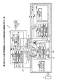
図10は、ラックマウントサーバを管理対象としたIO仮想化技術の一例を示す図である。図10に示すように、情報処理システム2000は、管理GUI装置2010と、管理サーバ2020と、ストレージ装置2030と、ラックマウントサーバ2040とを有する。また、ラックマウントサーバ2040のマザーボード2100は、CPU(Central Processing Unit)2110とBMC(Baseboard Management Controller)2120とを搭載する。BMC2120は、サーバ管理専用のユニットであり、ハードウェア障害等のためにオペレ−ティングシステムがダウンしている際においても、障害通報機能およびリモートコントロール機能を管理者に提供する。
FIG. 10 is a diagram illustrating an example of an IO virtualization technology that manages a rack mount server. As illustrated in FIG. 10, the
このような情報処理システム2000では、まず、管理者が管理GUI装置2010を通して、管理対象であるラックマウントサーバ2040の仮想アドレスを定義する。続いて、管理サーバ2020は、ラックマウントサーバ2040内のBMC2120に、IPMI(Intelligent Platform Management Interface)と呼ばれるインターフェースを用いて仮想アドレステーブルに管理対象の仮想アドレスを設定する。
In such an
そして、管理者が管理サーバ2020から管理対象であるラックマウントサーバ2040の電源をBMC2120経由でオンにする。これにより、BMC2120は、ラックマウントサーバ2040のCPU2110を経由して、CPU2110が有するNIC及びHBAへ仮想アドレスを設定する。このようにして、情報処理システム2000では、ラックマウントサーバ2040にIO仮想化技術が適用される。
Then, the administrator turns on the power of the
また、これにより、ラックマウントサーバ2040は、ストレージ装置2030にアクセスが可能となり、ストレージ装置2030が記憶するOS、プログラム及びデータからブートを実行して起動する。
As a result, the
しかしながら、上述した従来の技術では、管理サーバとBMCとのネットワークに障害が生じた場合に、管理対象サーバを起動することができないという課題がある。 However, the above-described conventional technique has a problem that the managed server cannot be started when a failure occurs in the network between the management server and the BMC.
BMCは、ラックマウントサーバ電源のオン、オフにかかわらず、かつ、OS(Operating System)を起動させていないプレブート環境下におけるラックマウントサーバの管理に用いられる。 The BMC is used for managing the rack mount server regardless of whether the power of the rack mount server is on or off, and in a pre-boot environment where the OS (Operating System) is not activated.
例えば、BMCは、遠隔地からコンソール画面を操作する管理者に、OSが起動する前のBIOS画面等をビデオリダイレクションで提供する。このプレブート環境下での操作は、ラックマウントサーバ上での業務の運用を開始する前に行われる。このため、もし運用を開始する前にBMCに異常が生じた場合には、管理者は、OSを立ち上げられなくなり、BMCの異常を検出する。また、一旦OSが立ち上がった後、BMCに生じる異常は、業務に直接支障をきたさない。 For example, the BMC provides the administrator who operates the console screen from a remote location with a BIOS screen before the OS is started by video redirection. The operation in the pre-boot environment is performed before starting the operation of the business on the rack mount server. For this reason, if an abnormality occurs in the BMC before the operation is started, the administrator cannot start the OS and detects an abnormality in the BMC. Also, once the OS has started up, an abnormality that occurs in the BMC does not directly interfere with the business.
このようなことから、BMCの通信ポートは一つであり、管理サーバとBMCとのネットワーク接続は二重化されていない。例えば、管理サーバは、BMC専用のポートを用いてBMCと通信し、BMCを制御する。また、ラックマウントサーバにおいて、一般的にBMCとの通信及びBMCの制御は、LoM(LAN on Mother Board)及び拡張LANカードから制御することはできない。 For this reason, the BMC has one communication port, and the network connection between the management server and the BMC is not duplicated. For example, the management server communicates with the BMC using a dedicated port for the BMC and controls the BMC. In a rack mount server, generally, communication with a BMC and control of the BMC cannot be controlled from a LoM (LAN on Mother Board) or an extended LAN card.
このため、管理サーバとBMCとのネットワーク接続に単一の障害点があり、管理サーバとBMCとのネットワーク経路上に障害が発生した場合、ラックマウントサーバは、仮想アドレスを設定するコマンドを管理サーバから受信できない。この結果、ラックマウントサーバは、仮想アドレスを設定できず、ストレージ装置にアクセスすることができなくなる。 For this reason, if there is a single point of failure in the network connection between the management server and the BMC, and a failure occurs on the network path between the management server and the BMC, the rack mount server issues a command for setting the virtual address. Cannot receive from. As a result, the rack mount server cannot set a virtual address and cannot access the storage apparatus.
1つの側面では、本発明は、管理装置と管理対象装置内の制御装置間で通信異常が生じた場合でも、管理対象装置を起動することができる情報処理システム及び仮想アドレス設定方法を提供することを目的とする。 In one aspect, the present invention provides an information processing system and a virtual address setting method capable of starting a management target device even when a communication abnormality occurs between the management device and a control device in the management target device. With the goal.
1つの案では、情報処理システムは、管理サーバと、管理サーバからの起動指示を受ける管理対象サーバを備え、管理対象サーバは、管理サーバとそれぞれネットワーク接続される、第1および第2のポートと、起動指示への対応の優先順位を規定した起動順位テーブルを記憶する記憶部と、第1のポートに接続され、起動により前記管理対象サーバを動作させる処理装置と、第2のポートに接続され、前記処理装置を制御する制御装置と、を有する。制御装置は、管理対象サーバへの電源投入を検知し、管理サーバに管理対象サーバへの電源投入を通知し、管理サーバは、電源投入の通知に応じて、管理対象サーバの第2のポートを通じて、制御装置に起動指示および第1のポートに設定されるアドレスを通知し、管理サーバが、制御装置に対する起動指示およびアドレス通知が失敗したことを検知したときは、第1のポートを通じて制御装置に起動指示および第1のポートに設定されるアドレスを通知し、制御装置は、管理サーバからの起動指示の受信に応じて、起動順位テーブルに従った起動指示を、処理装置に対して行う。 In one proposal, an information processing system includes a management server and a managed server that receives a start instruction from the management server, and the managed server includes a first port and a second port that are network-connected to the management server, respectively. A storage unit that stores a startup order table that defines the priority order for responding to startup instructions; a processing unit that is connected to the first port and that operates the managed server upon startup; and a second port. And a control device for controlling the processing device. The control device detects power-on to the managed server, notifies the management server of power-on to the managed server, and the management server responds to the power-on notification through the second port of the managed server. When the management server detects that the activation instruction and the address notification for the control device have failed, the control device is notified of the activation instruction and the address set for the first port. In response to the activation instruction and the address set in the first port, the control device issues an activation instruction according to the activation order table to the processing device in response to reception of the activation instruction from the management server.
1実施形態における情報処理システムによれば、管理装置と管理対象装置内の制御装置間で通信異常が生じた場合でも、管理対象装置を起動することができる。 According to the information processing system in the embodiment, even when a communication abnormality occurs between the management device and the control device in the management target device, the management target device can be activated.
以下に、本願の開示する情報処理システム及び仮想アドレス設定方法の実施例を図面に基づいて詳細に説明する。なお、この実施例によりこの発明が限定されるものではない。そして、各実施例は、処理内容を矛盾させない範囲で適宜組み合わせることが可能である。 Embodiments of an information processing system and a virtual address setting method disclosed in the present application will be described below in detail with reference to the drawings. Note that the present invention is not limited to the embodiments. Each embodiment can be appropriately combined within a range in which processing contents are not contradictory.
実施例1では、図1から図8を用いて、情報処理システムの構成、情報処理システムにおける処理動作、情報処理システムによる処理手順及び効果などについて説明する。 In the first embodiment, the configuration of the information processing system, the processing operation in the information processing system, the processing procedure and effects of the information processing system, and the like will be described using FIGS.
[実施例1に係る情報処理システム10の構成]
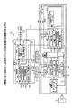
図1を用いて、実施例1に係る情報処理システム10の機能構成を説明する。図1は、実施例1に係る情報処理システム10の機能構成を示す機能ブロック図である。図1に示すように、情報処理システム10は、管理GUI(Graphical User Interface)装置11と、管理サーバ20と、ストレージ装置30と、ラックマウントサーバ40とを有する。
[Configuration of
The functional configuration of the
情報処理システム10では、管理GUI装置11と、管理サーバ20とがネットワークにより互いに通信可能に接続する。また、管理サーバ20とラックマウントサーバ40とが、イーサースイッチ13またはイーサースイッチ14を介して互いに通信可能に接続する。また、ストレージ装置30とラックマウントサーバ40とが、FCスイッチ15またはFCスイッチ16を介して互いに通信可能に接続する。
In the
管理GUI装置11は、管理者から各種設定を受付ける。例えば、管理GUI装置11は、管理対象のサーバであるラックマウントサーバ40の仮想アドレスの定義を管理者から受付ける。管理サーバ20は、ラックマウントサーバ40の設定や状態の管理、ブート制御、異常検出など、ラックマウントサーバ40の管理及び制御を行う。なお、管理サーバ20の詳細な構成については、後述する。管理サーバ20は管理対象装置を管理装置の一例である。
The
ストレージ装置30は、図示しないHDD(Hard Disk Drive)を有し、各種のデータやプログラムを記憶する。例えば、ストレージ装置30は、ラックマウントサーバ40が、SANブートに用いるOS、プログラム及びデータを記憶する。
The
ラックマウントサーバ40は、マザーボード100を有する。このマザーボード100は、記憶部200と、BMC(Baseboard Management Controller)300と、演算処理装置400とを有する。なお、記憶部200、BMC300、及び演算処理装置400の機能については後述する。ラックマウントサーバ40は管理対象装置である情報処理装置の一例であり、BMCは管理対象装置内の制御装置の一例である。
The
このラックマウントサーバ40は、ストレージ装置30が記憶するデータにアクセスし、各種演算処理を実行する。また、ラックマウントサーバ40は、演算処理結果をストレージ装置30に記憶させる。なお、以下の説明では、ラックマウントサーバ40のことを、適宜「管理対象サーバ」として記載する。また、このラックマウントサーバ40は、電源12から電力を供給される。
The
このような情報処理システム10において、管理サーバ20は、BMC300との間のネットワークに異常が生じた場合、演算処理装置400を介してBMC300に起動を指示する。また、BMC300は、演算処理装置400から起動を指示された場合、後述する仮想アドレステーブル311が記憶する仮想アドレスを演算処理装置400に転送する。そして、演算処理装置400は、BMC300から仮想アドレスを受信した場合、自装置が有するポートにこの仮想アドレスを設定する。
In such an
なお、図1では、情報処理システム10において、管理対象サーバがラックマウントサーバ40の1台である例を示したが、情報処理システム10が有する管理対象サーバの数は、図示した数に限定されるものではない。また、情報処理システム10において、ラックマウントサーバ40と接続するストレージ装置30の数は、図示した数に限定されるものではない。
1 illustrates an example in which the management target server is one of the
[管理サーバ20の機能構成]
続いて、図1を用いて、管理サーバ20の機能構成を説明する。図1に示すように、管理サーバ20は、NIC(Network Interface Card)21及び22と、記憶部23と、制御部24とを有する。
[Functional configuration of management server 20]
Next, the functional configuration of the
NIC21は、管理サーバ20とラックマウントサーバ40とをイーサースイッチ13を介して接続するインターフェースである。NIC22は、管理サーバ20とラックマウントサーバ40とをイーサースイッチ14を介して接続するインターフェースである。
The
記憶部23は、例えばRAM(Random Access Memory)などの半導体メモリ素子である。記憶部23は、仮想アドレス定義ファイル23aと、IPMI(Intelligent Platform Management Interface)−KCS(Keyboard Controller Style)制御NBP(Network Bootstrap Program)23bとを有する。
The
仮想アドレス定義ファイル23aは、管理者から受付けた、管理対象サーバであるラックマウントサーバ40の仮想アドレスを記憶する。IPMI−KCS制御NBP23bは、KCSインターフェース経由でBMC300を制御する命令である。このIPMI−KCS制御NBP23bは、PXE(Preboot eXecution Environment)経由で管理サーバ20から管理対象サーバの演算処理装置400にダウンロードされる。
The virtual
制御部24は、CPU(Central Processing Unit)やMPU(Micro Processing Unit)などの電子回路であり、IPMI−LAN制御部24aと、ブート制御部24bと、PXE制御部24cと、SNMPトラップ受信部24dとを有する。
The
IPMI−LAN制御部24aは、LANインターフェース経由でIPMI仮想アドレス設定コマンドやIPMIブートコマンドを送信することによって、後述するBMC300を制御する。
The IPMI-
例えば、IPMI−LAN制御部24aは、SNMPトラップ受信部24dから管理対象サーバを特定する情報を受信した場合、管理対象サーバの仮想アドレスを仮想アドレス定義ファイル23aから検索して読出す。そして、IPMI−LAN制御部24aは、IPMIインターフェースを利用して読出した仮想アドレスとIPMI仮想アドレス設定コマンドとをBMC300のIPMIサーバ部322に送信する。
For example, when the IPMI-
また、IPMI−LAN制御部24aは、ブート制御部24bから管理対象サーバをブートさせる指示を受付けた場合、以下の処理を実行する。すなわち、IPMI−LAN制御部24aは、IPMIブートコマンドを発行し、発行したIPMIブートコマンドと、仮想アドレスとを管理対象サーバにIPMI−LANインターフェースを介してBMC300のIPMIサーバ部322に送信する。
When the IPMI-
また、IPMI−LAN制御部24aは、送信したIPMIブートコマンドが送信エラーになる場合、管理対象サーバのNIC401及びNIC402にWOL(Wake up On LAN)のマジックパケットを送信する。
Also, when the transmitted IPMI boot command results in a transmission error, the IPMI-
ブート制御部24bは、管理対象サーバの電源を投入する指示を管理者から受付けた場合、仮想アドレスをBMC300に送信させるとともに、管理対象サーバをブートさせる指示をIPMI−LAN制御部24aに出力する。
When the
PXE制御部24cは、管理対象サーバからのPXEブート要求に応答し、IPMI−KCS制御NBP23bと管理対象サーバの仮想アドレスとを管理対象サーバへ送信する。例えば、PXE制御部24cは、PXEブート要求を演算処理装置400から受信し、PXEブート要求に含まれる要求元を特定する情報から管理対象サーバを判別し、仮想アドレス定義ファイル23aから管理対象サーバの仮想アドレスを検索する。また、PXE制御部24cは、IPMI−KCS制御NBP23bを記憶部23から読出す。そして、PXE制御部24cは、読出したIPMI−KCS制御NBP23bと管理対象サーバの仮想アドレスとを演算処理装置400のNBP実行部413に送信する。
In response to the PXE boot request from the managed server, the
SNMPトラップ受信部24dは、ラックマウントサーバ40の電源プラグがオンされ、後述するBMC300への電源が投入された時に、SNMPトラップをBMC300の初期化部321から受信する。SNMPトラップ受信部24dは、SNMPトラップがコールドスタートを指示する場合、SNMPトラップに含まれる送信元情報を、管理対象サーバを特定する情報としてIPMI−LAN制御部24aに出力する。
The SNMP
[ストレージ装置30の機能構成]
次に、図1を用いて、実施例1に係るストレージ装置30の構成を説明する。実施例1に係るストレージ装置30は、HBA(Host Bus Adapter)31及びHBA32と、LUN(Logical Unit Number)33、LUN34及びLUN35とを有する。
[Functional Configuration of Storage Device 30]
Next, the configuration of the
HBA31は、ストレージ装置30とラックマウントサーバ40とをFCスイッチ15を介して接続するインターフェースである。HBA32は、ストレージ装置30とラックマウントサーバ40とをFCスイッチ16を介して接続するインターフェースである。
The
LUN33は、ストレージ装置30が有するHDDを論理的に分割し、1台のHDDとしてラックマウントサーバ40により認識される論理的なディスク装置である。また、LUN34及びLUN35もLUN33と同様に、ストレージ装置30が有するHDDを論理的に分割し、1台のHDDとしてラックマウントサーバ40により認識される論理的なディスク装置である。
The
また、ストレージ装置30は、ラックマウントサーバ40のHBA403及び404のポートに割り当てられたWWPN(World Wide Port Name)値と、LUNとの対応情報を有する。そして、ストレージ装置30は、LUNに対応付けられた特定のWWPNを有するラックマウントサーバ40のHBA403またはHBA404のポートからのアクセスのみを許可する。例えば、ストレージ装置30は、LUN33とラックマウントサーバ40のHBA403とが対応付けられている場合、LUN33に対するHBA403からのアクセスを許可し、HBA404からのアクセスを許可しない。
The
[ラックマウントサーバ40の機能構成]
次に、図1を用いて、実施例1に係るラックマウントサーバ40の構成を説明する。実施例1に係るラックマウントサーバ40は、マザーボード100を有する。このマザーボード100は、記憶部200と、BMC300と、演算処理装置400とを有する。なお、記憶部200と、BMC300と、演算処理装置400とはそれぞれバスによって接続される。
[Functional configuration of rack mount server 40]
Next, the configuration of the
記憶部200は、例えば、CMOS(Complementary Metal Oxide Semiconductor)メモリであり、BIOS(Basic Input/Output System)の情報とブートオーダテーブル201とを記憶する。
The
ブートオーダテーブル201は、演算処理装置400のブートオーダの優先順位を示す情報を記憶する。例えば、ブートオーダテーブル201は、SANブートを優先する場合、HBA403、HBA404、NIC401、NIC402の順でブートオーダを記憶する。また、ブートオーダテーブル201は、管理サーバ20からのPXEブートを優先する場合、NIC401、NIC402、HBA403、HBA404の順でブートオーダを記憶する。
The boot order table 201 stores information indicating the boot order priority order of the
BMC300は、電源プラグが電源12に差込まれた場合、常時通常動作を開始する。例えば、BMC300は、ハードウェア障害等のためにオペレ−ティングシステムがダウンしている際においても、障害通報機能およびリモートコントロール機能を管理者に提供する。また、BMC300は、管理サーバ20から受信した仮想アドレスを後述する仮想アドレステーブル311に記憶させる。
The
演算処理装置400は、各種演算処理を実行する。また、演算処理装置400は、自装置の電源が投入された場合、ストレージ装置30からSANブートまたは管理サーバ20からPXEブートを実行する。
The
[BMC300の機能構成]
次に、図1を用いて、BMC300の機能構成を説明する。図1に示すように、BMC300は、NIC301と、記憶部310と、制御部320とを有する。
[Functional configuration of BMC 300]
Next, the functional configuration of the
NIC301は、管理サーバ20とBMC300とをイーサースイッチ14を介して接続するインターフェースである。なお、BMC300は、このNIC301のみを介して管理サーバ20と接続する。
The
記憶部310は、例えばRAMなどの半導体メモリ素子であり、仮想アドレステーブル311を有する。仮想アドレステーブル311は、演算処理装置400のNIC401及びNIC402と、HBA403及びHBA404に設定する仮想アドレスを記憶する。なお、仮想アドレステーブル311が記憶する情報については後述する。
The
制御部320は、例えば、CPUやMPUなどの電子回路であり、初期化部321と、IPMIサーバ部322と、ブートオーダ変更部323と、電源制御部324とを有する。
The
初期化部321は、ラックマウントサーバの電源プラグがオンされ、BMC300への電源が投入されたことを契機に、コールドスタートを指示するSNMPトラップを管理サーバ20のSNMPとラップ受信部24dに送信する。
When the power plug of the rack mount server is turned on and the power to the
IPMIサーバ部322は、IPMI仮想アドレス設定コマンドと仮想アドレスとを管理サーバ20のIPMI-LAN制御部24aから受信し、仮想アドレスを仮想アドレステーブル311に格納する。
The
また、IPMIサーバ部322は、IPMI仮想アドレス設定コマンドと仮想アドレスとを管理サーバ20のIPMI-LAN制御部24aから受信できず、タイムアウトした場合、初期化部321にSNMPトラップを所定の回数、管理サーバ20に再送させる。そして、IPMIサーバ部322は、再送回数が所定の回数に達した場合、管理サーバ20とのネットワークに障害が生じたと判定し、ブートオーダ変更部323にネットワークに障害が生じたことを通知する。
In addition, when the
また、IPMIサーバ部322は、IPMIブートコマンドを管理サーバ20のIPMI-LAN制御部24aから受信した場合、電源制御部324に演算処理装置400の電源オンを指示する。
Further, when the
また、IPMIサーバ部322は、IPMI−KCS制御NBP23bを実行したNBP実行部413から、KCSインターフェース経由で仮想アドレスを受信した場合、受信した仮想アドレスを仮想アドレステーブル311に格納する。
Further, when the
ブートオーダ変更部323は、演算処理装置400のブートオーダの優先順位を変更する。ブートオーダ変更部323は、SANブートを優先する場合、ブートオーダテーブル201に、例えば、HBA403、HBA404、NIC401、NIC402の順でブートオーダを記憶させる。また、ブートオーダ変更部323は、管理サーバ20からのPXEブートを優先する場合、ブートオーダテーブル201に、例えば、NIC401、NIC402、HBA403、HBA404の順でブートオーダを記憶させる。
The boot
また、ブートオーダ変更部323は、管理サーバ20からのPXEブートを優先するようにブートオーダテーブル201を変更した場合、電源制御部324に演算処理装置400の電源オンを指示する。
In addition, when the boot order table 201 is changed so that the PXE boot from the
電源制御部324は、演算処理装置400の電源オン及びオフを制御する。例えば、電源制御部324は、演算処理装置400の電源オンをIPMIサーバ部322から指示された場合、演算処理装置400の電源をオンにする。また、電源制御部324は、演算処理装置400の電源オンをブートオーダ変更部323から指示された場合、演算処理装置400の電源をオンにする。
The
また、電源制御部324は、WOLのマジックパケットをNIC401またはNIC402を介してIPMI−LAN制御部24aを受信した場合、演算処理装置400の電源をオンにする。
In addition, when the IPMI-
また、電源制御部324は、SMASH CLPインターフェースを用いて、仮想アドレス設定部411に仮想アドレスを出力する。
Further, the
[演算処理装置400の機能構成]
次に、図1を用いて、演算処理装置400の機能構成を説明する。図1に示すように、演算処理装置400は、NIC401及びNIC402と、HBA403及びHBA404と、制御部410とを有する。なお、演算処理装置400は、NICとHBAとを統合したインターフェースであるCNA(Converged Network Adapter)を有するようにしてもよい。
[Functional Configuration of Arithmetic Processing Device 400]
Next, the functional configuration of the
NIC401は、管理サーバ20と演算処理装置400とをイーサースイッチ13を介して接続するインターフェースである。NIC402は、管理サーバ20と演算処理装置400とをイーサースイッチ14を介して接続するインターフェースである。なお、NIC401及びNIC402のポートには、仮想アドレスが設定される。
The
HBA403は、ストレージ装置30と演算処理装置400とをFCスイッチ15を介して接続するインターフェースである。HBA404は、ストレージ装置30と演算処理装置400とをFCスイッチ16を介して接続するインターフェースである。なお、HBA403及びHBA404のポートには、仮想アドレスが設定される。
The
制御部410は、例えば、CPUやMPUなどの電子回路であり、仮想アドレス設定部411と、PXEブート部412と、NBP実行部413とを有する。
The
仮想アドレス設定部411は、BMC300の電源制御部324から仮想アドレスを受信し、NIC401及び402と、HBA403及び404とに、仮想アドレスを設定する。例えば、仮想アドレス設定部411は、PCI(Peripheral Component Interconnect)オプションROM(Read Only Memory)インターフェースを用いて、仮想アドレスを設定する。
The virtual
PXEブート部412は、演算処理装置400の電源がオンにされた時に、ブートオーダテーブル201の優先順位が管理サーバ20からのPXEブートを優先することを示す場合、PXEブートを要求するPXEブート要求を管理サーバ20に送信する。
The
NBP実行部413は、管理サーバ20からIPMI−KCS制御NBP23bを受信する。そして、NBP実行部413は、IPMI−KCS制御NBP23bを実行し、KCSインターフェース経由で仮想アドレスをBMC300のIPMIサーバ部322へ送信する。これにより、BMC300のIPMIサーバ部322は、仮想アドレステーブル311に仮想アドレスを設定する。
The
[仮想アドレス]
次に図2Aから図2Cを用いて、仮想アドレスについて説明する。ここでは、図2Aを用いて、仮想アドレス定義ファイル23aが記憶するデータ構造を説明し、図2Bを用いて、BMC300が記憶する初期設定値を説明し、図2Cを用いて、仮想アドレステーブル311が記憶するデータ構造を説明する。
[Virtual address]
Next, a virtual address will be described with reference to FIGS. 2A to 2C. Here, the data structure stored in the virtual
図2Aは、仮想アドレス定義ファイル23aが記憶するデータ構造の一例を示す図である。図2Aに示すように、仮想アドレス定義ファイル23aは、「BMC IP(Internet Protocol)」、「NIC IP−1」、「NIC IP−2」のそれぞれに対応付けたアドレスを記憶する。また、仮想アドレス定義ファイル23aは、「NIC仮想MAC(Media Access Control)−1」、「NIC仮想MAC−2」のそれぞれに対応付けたアドレスを記憶する。また、仮想アドレス定義ファイル23aは、「HBA仮想WWPN(World Wide Port Name)−1」、「HBA仮想WWPN−2」のそれぞれに対応付けたアドレスを記憶する。なお、仮想アドレス定義ファイル23aが記憶するデータは、管理GUI装置11を介して管理者により設定される。
FIG. 2A is a diagram illustrating an example of a data structure stored in the virtual
「BMC IP」は、BMC300のIPアドレスを示す。例えば「BMC IP」には、「aa:bb:cc:01」が設定される。「NIC IP−1」は、NIC401のIPアドレスを示す。例えば「NIC IP−1」には、「aa:bb:cc:02」が設定される。「NIC IP−2」は、NIC402のIPアドレスを示す。例えば「NIC IP−2」には、「aa:bb:cc:03」が設定される。
“BMC IP” indicates the IP address of the
また、「NIC仮想MAC−1」は、NIC401に仮想的に割当てられたMACアドレスを示す。例えば、「NIC仮想MAC−1」には、「aa:bb:cc:dd:ee:01」が設定される。「NIC仮想MAC−2」は、NIC402に仮想的に割当てられたMACアドレスを示す。例えば、「NIC仮想MAC−2」には、「aa:bb:cc:dd:ee:02」が設定される。
“NIC virtual MAC-1” indicates a MAC address virtually assigned to the
また、「HBA仮想WWPN−1」は、HBA403に仮想的に割当てられたWWPNを示す。例えば、「HBA仮想WWPN−1」には、「aa:bb:cc:dd:ee:ff:gg01」が設定される。「HBA仮想WWPN−2」は、HBA404に仮想的に割当てられたWWPNを示す。例えば、「HBA仮想WWPN−2」には、「aa:bb:cc:dd:ee:ff:gg02」が設定される。
“HBA virtual WWPN-1” indicates the WWPN virtually allocated to the
図2Bは、BMC300が記憶する初期設定値の一例を示す図である。図2Bに示すように、BMC300は、初期設定値として「BMC IP」、「管理サーバIP−1」、「管理サーバIP−2」のそれぞれに対応付けたアドレスを記憶する。なお、この初期設定値は、例えば、BMC300が有する記憶部310が記憶する。
FIG. 2B is a diagram illustrating an example of initial setting values stored in the
「BMC IP」は、BMC300のIPアドレスを示す。例えば「BMC IP」には、「aa:bb:cc:01」が設定される。「管理サーバIP−1」は、管理サーバ20のIPアドレスを示す。例えば「管理サーバIP−1」には、「aa:bb:cc:02」が設定される。「管理サーバIP−2」は、管理サーバ20のIPアドレスを示す。例えば「管理サーバIP−2」には、「aa:bb:cc:03」が設定される。
“BMC IP” indicates the IP address of the
図2Cは、仮想アドレステーブル311が記憶するデータ構造の一例を示す図である。図2Cに示すように、BMC300が有する仮想アドレステーブル311は、「NIC仮想MAC−1」、「NIC仮想MAC−2」、「HBA仮想WWPN−1」、「HBA仮想WWPN−2」のそれぞれに対応付けたアドレスを記憶する。
FIG. 2C is a diagram illustrating an example of a data structure stored in the virtual address table 311. As shown in FIG. 2C, the virtual address table 311 of the
仮想アドレステーブル311が記憶する「NIC仮想MAC−1」、「NIC仮想MAC−2」、「HBA仮想WWPN−1」、「HBA仮想WWPN−2」には、仮想アドレス定義ファイル23aから読出された値がIPMIサーバ部322により設定される。このため、仮想アドレステーブル311が記憶する「NIC仮想MAC−1」及び「NIC仮想MAC−2」は、図2Aに示した仮想アドレス定義ファイル23aが記憶する「NIC仮想MAC−1」及び「NIC仮想MAC−2」と同様である。また、仮想アドレステーブル311が記憶する「HBA仮想WWPN−1」及び「HBA仮想WWPN−2」は、図2Aに示した仮想アドレス定義ファイル23aが記憶する「HBA仮想WWPN−1」及び「HBA仮想WWPN−2」と同様である。
The “NIC virtual MAC-1”, “NIC virtual MAC-2”, “HBA virtual WWPN-1”, and “HBA virtual WWPN-2” stored in the virtual address table 311 are read from the virtual
[情報処理システム10における処理動作]
次に、図3から図6を用いて、情報処理システム10における処理動作を説明する。ここでは、図3を用いて、正常時におけるBMC300への仮想アドレス設定処理の処理動作を説明し、図4を用いて、正常時における演算処理装置400によるOS起動処理の処理動作を説明する。また、図5を用いて、異常時における演算処理装置400によるOS起動処理の処理動作を説明し、図6を用いて、異常時におけるBMC300への仮想アドレス設定処理の処理動作を説明する。
[Processing Operation in Information Processing System 10]
Next, processing operations in the
(正常時におけるBMC300への仮想アドレス設定処理)
図3は、正常時におけるBMC300への仮想アドレス設定処理の処理動作を示す図である。図3に示すように、管理GUI装置11は、管理対象サーバの仮想アドレスの設定を管理者から受付ける。そして、管理サーバ20は、管理GUI装置11を介して管理者から受付けた管理対象サーバの仮想アドレスを仮想アドレス定義ファイル23aに格納する(ステップS1)。
(Virtual address setting process to BMC300 at normal time)
FIG. 3 is a diagram showing the processing operation of the virtual address setting process for the
ラックマウントサーバ40の電源プラグが管理者により投入された場合、BMC300の初期化部321は、初期設定情報を参照し、管理サーバ20へSNMPトラップを送信する(ステップS2)。そして、管理サーバ20のSNMPトラップ受信部24dは、BMC300からSNMPトラップを受信する。ここで、SNMPトラップ受信部24dは、SNMPトラップがコールドスタートを指示する場合、送信元情報を管理対象サーバ情報としてIPMI−LAN制御部24aに出力する(ステップS3)。
When the power plug of the
IPMI−LAN制御部24aは、管理対象サーバの仮想アドレスを仮想アドレス定義ファイル23aから検索して読出す(ステップS4)。そして、IPMI−LAN制御部24aは、IPMIインターフェースを利用して読出した仮想アドレスをBMC300へ送信する(ステップS5)。
The IPMI-
IPMIサーバ部322は、管理サーバ20から仮想アドレスを受信し、受信した仮想アドレスを仮想アドレステーブル311に格納する(ステップS6)。また、ブートオーダ変更部323は、ブートオーダテーブル201にSANブートを優先させるブートオーダを設定する(ステップS7)。
The
(正常時における演算処理装置400によるOS起動処理)
図4は、正常時における演算処理装置400によるOS起動処理の処理動作を示す図である。図4に示すように、管理GUI装置11は、管理対象サーバの電源を投入する指示を管理者から受付ける。そして、管理サーバ20のブート制御部24bは、仮想アドレス定義ファイル23aを参照し、IPMI−LAN制御部24aに管理対象サーバの仮想アドレスを出力するとともに、管理対象サーバをブートさせる指示を出力する(ステップS11)。
(OS startup processing by the
FIG. 4 is a diagram showing the processing operation of the OS startup process by the
IPMI−LAN制御部24aは、IPMIブートコマンドを発行し、発行したIPMIブートコマンドと、仮想アドレスとを管理対象サーバにIPMI−LANインターフェースを介して送信する(ステップS12)。
The IPMI-
IPMIサーバ部322は、管理サーバ20からIPMIブートコマンドと、仮想アドレスとを受信する(ステップS12)。そして、IPMIサーバ部322は、受信した仮想アドレスと、仮想アドレステーブル311に格納されている仮想アドレスとを比較する(ステップS13)。そして、IPMIサーバ部322は、受信した仮想アドレスと異なる仮想アドレスが格納されている場合には、受信した仮想アドレスを仮想アドレステーブル311に格納する。
The
そして、電源制御部324は、演算処理装置400の電源をオンにし、SMASH CLPインターフェースを用いて、仮想アドレス設定部411に仮想アドレスを出力する(ステップS14)。仮想アドレス設定部411は、PCIオプションROMインターフェースを用いて、NIC401及び402と、HBA403及び404とに、仮想アドレスを設定する。
Then, the
(異常時における演算処理装置400によるOS起動処理)
図3及び図4を用いて、情報処理システム10において、管理サーバ20と、BMC300とのネットワークが正常である場合の処理動作について説明した。ところで、情報処理システム10において、管理サーバ20と、BMC300とのネットワークに異常が生じる場合がある。そこで、図5及び図6を用いて、管理サーバ20と、BMC300とのネットワークに異常が生じた場合の情報処理システム10における処理動作について説明する。なお、このネットワークの異常には、例えば、NIC22の故障、NIC301の故障、イーサースイッチ14の故障、NIC22とNIC301との間のいずれかのケーブルの異常などが含まれる。
(OS startup processing by the
The processing operation when the network between the
図5は、異常時における演算処理装置400によるOS起動処理の処理動作を示す図である。なお、図5は、BMC300の仮想アドレステーブル311に仮想アドレスを設定した後、管理サーバ20と、BMC300とのネットワークに異常が生じた場合を示す。
FIG. 5 is a diagram illustrating the processing operation of the OS startup process performed by the
図5に示すように、管理GUI装置11は、管理対象サーバの電源を投入する指示を管理者から受付ける。そして、管理サーバ20のブート制御部24bは、仮想アドレス定義ファイル23aを参照し、IPMI−LAN制御部24aに管理対象サーバの仮想アドレスを出力するとともに、管理対象サーバをブートさせる指示を出力する(ステップS21)。
As shown in FIG. 5, the
IPMI−LAN制御部24aは、IPMIブートコマンドを発行し、発行したIPMIブートコマンドと、仮想アドレスとを管理対象サーバにIPMI−LANインターフェースを介して送信する(ステップS22)。IPMI−LAN制御部24aは、送信エラーになった場合、所定の回数、発行したIPMIブートコマンドと、仮想アドレスとを管理対象サーバに再送信する。そして、IPMI−LAN制御部24aは、所定の回数、再送信しても送信エラーになる場合、送信エラーになったことをブート制御部24bに通知する(ステップS23)。
The IPMI-
そして、IPMI−LAN制御部24aは、管理対象サーバのNIC401及び402にWOLのマジックパケットを送信する(ステップS24)。また、電源制御部324は、演算処理装置400の電源をオンにし、仮想アドレス設定部411に仮想アドレスをSMASH CLPインターフェースを用いて、出力する(ステップS25)。仮想アドレス設定部411は、PCIオプションROMインターフェースを用いて、NIC401及び402と、HBA403及び404とに、仮想アドレスを設定する。
The IPMI-
(異常時におけるBMC300への仮想アドレス設定処理)
図6は、異常時におけるBMC300への仮想アドレス設定処理の処理動作を示す図である。図6に示すように、管理GUI装置11は、管理対象サーバの仮想アドレスの設定を管理者から受付ける。そして、管理サーバ20は、管理GUI装置11を介して管理者から受付けた管理対象サーバの仮想アドレスを仮想アドレス定義ファイル23aに格納する(ステップS31)。
(Virtual address setting process to BMC300 at the time of abnormality)
FIG. 6 is a diagram illustrating a processing operation of a virtual address setting process for the
ラックマウントサーバ40の電源プラグが管理者により投入された場合、BMC300の初期化部321は、初期設定情報を参照し、管理サーバ20へSNMPトラップを送信する(ステップS32)。
When the power plug of the
IPMIサーバ部322は、IPMI仮想アドレス設定コマンドと仮想アドレスとを管理サーバ20から受信できず、タイムアウトした場合には、初期化部321にSNMPトラップを所定の回数管理サーバ20に再送させる。そして、IPMIサーバ部322は、再送回数が所定の回数に達した場合、管理サーバ20とのネットワークに障害が生じたと判定し、ブートオーダ変更部323にネットワークに障害が生じたことを通知する(ステップS33)。
When the
ブートオーダ変更部323は、管理サーバ20からのPXEブートを優先させたブートオーダに変更する(ステップS34)。そして、BMC300の電源制御部324は、演算処理装置400の電源をオンにする。
The boot
演算処理装置400のPXEブート部412は、PXEブート要求を管理サーバ20に送信する(ステップS35)。管理サーバ20のPXE制御部24cは、PXEブート要求を演算処理装置400から受信し、以下の処理を実行する。すなわち、PXE制御部24cは、PXEブート要求に含まれる要求元を特定する情報から管理対象サーバを判別して、仮想アドレス定義ファイル23aから管理対象サーバの仮想アドレスを検索する(ステップS36)。
The
また、PXE制御部24cは、IPMI−KCS制御NBP23bを読出し(ステップS37)、読出したIPMI−KCS制御NBP23bを演算処理装置400に送信する(ステップS38)。
The
演算処理装置400のNBP実行部413は、IPMI−KCS制御NBP23bを実行する。これにより、NBP実行部413は、IPMI仮想アドレス設定コマンドを発行し、BMC300に送信する(ステップS39)。
The
BMC300のIPMIサーバ部322は、IPMI仮想アドレス設定コマンドを受信し、IPMI仮想アドレス設定コマンドから読出した仮想アドレスを仮想アドレステーブル311に設定する(ステップS40)。
The
BMC300の電源制御部324は、CPUの電源をオフにする。また、BMC300のブートオーダ変更部323は、ストレージ装置30からのSANブートを優先させたブートオーダに変更する(ステップS41)。
The
[情報処理システム10による処理手順]
次に、図7及び図8を用いて、情報処理システム10による処理手順を説明する。ここで、図7を用いて、BMC300への仮想アドレス設定処理の処理手順を説明し、図8を用いて、演算処理装置400によるOS起動処理の処理手順を説明する。
[Processing Procedure by Information Processing System 10]
Next, a processing procedure performed by the
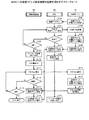
(BMC300への仮想アドレス設定処理)
図7は、BMC300への仮想アドレス設定処理の処理手順を示すフローチャートである。図7に示すように、管理サーバ20は、管理者から仮想アドレスの入力を受付け、仮想アドレス定義ファイル23aに受付けた仮想アドレスを設定する(ステップS101)。続いて、管理者が管理対象サーバの電源プラグをオンにすることで、BMC300は、通電する(ステップS102)。
(Virtual address setting process to BMC300)
FIG. 7 is a flowchart showing a processing procedure of a virtual address setting process for the
BMC300では、初期化部321は、SNMPトラップを管理サーバ20に送信する(ステップS103)。管理サーバ20では、SNMPトラップ受信部24dは、SNMPトラップを受信する(ステップS104)。SNMPトラップ受信部24dは、初期化スタートしたことを意味するコールドスタートを示すSNMPトラップであれば、送信元情報を管理対象サーバ情報としてIPMI−LAN制御部24aに出力する。
In the
IPMI−LAN制御部24aは、仮想アドレス定義ファイル23aから管理対象サーバの仮想アドレスを読込む(ステップS105)。そして、IPMI−LAN制御部24aは、IPMI仮想アドレス設定コマンドを発行し、BMC300に送信する(ステップS106)。ステップS106の終了後、実施例1に係る情報処理システム10では、BMC300がステップS119を実行する。
The IPMI-
また、BMC300では、IPMIサーバ部322は、初期化部321によりSNMPトラップが管理サーバ20に送信された場合、管理サーバ20からIPMI仮想アドレス設定コマンドを受信したか否かを判定する(ステップS107)。ここで、IPMIサーバ部322は、管理サーバ20からIPMI仮想アドレス設定コマンドを受信したと判定した場合(ステップS107、Yes)、ステップS119に移行する。
In the
また、IPMIサーバ部322は、IPMI仮想アドレス設定コマンドを管理サーバ20から受信できずタイムアウトした場合(ステップS107、No)、以下の処理を実行する。すなわち、IPMIサーバ部322は、初期化部321にSNMPトラップを管理サーバ20に再送させる。ここで、IPMIサーバ部322は、この再送回数が所定の回数に達したか否かを判定する(ステップS108)。なお、ここでは、所定の回数が5回に設定されるものとして説明するが、所定の回数はこの回数に限定されるものではない。IPMIサーバ部322は、再送回数が5回に達していないと判定した場合(ステップS108、No)、初期化部321にSNMPトラップを管理サーバ20に再送させる。
When the
IPMIサーバ部322により再送回数が5回に達したと判定された場合(ステップS108、Yes)、演算処理装置400のブートオーダ変更部323は、ブートオーダを変更する(ステップS109)。例えば、ブートオーダ変更部323は、管理サーバ20からのPXEブートを優先させたブートオーダに変更する。
When it is determined by the
続いて、BMC300の電源制御部324は、演算処理装置400の電源をオンにする(ステップS110)。そして、演算処理装置400のPXEブート部412は、管理サーバ20にPXEブートを要求するPXEブート要求を送信する(ステップS111)。
Subsequently, the
管理サーバ20のPXE制御部24cは、PXEブート要求を演算処理装置400から受信し(ステップS112)、PXEブート要求の要求元から管理対象サーバを判定し、仮想アドレス定義ファイル23aから仮想アドレスを読込む(ステップS113)。また、PXE制御部24cは、IPMI−KCS制御NBP23bを読込む(ステップS114)。PXE制御部24cは、読込んだ仮想アドレスとIPMI−KCS制御NBP23bとを演算処理装置400に送信する。
The
NBP実行部413は、PXEブート部412によりPXEブート要求を管理サーバ20に送信された場合、管理サーバ20から仮想アドレスとIPMI−KCS制御NBP23bとを受信したか否かを判定する(ステップS115)。NBP実行部413は、仮想アドレスとIPMI−KCS制御NBP23bとを管理サーバ20から受信できず、タイムアウトした場合(ステップS115、No)、以下の処理を実行する。すなわち、NBP実行部413は、PXEブート部412にPXEブート要求を管理サーバ20に再送させる。ここで、NBP実行部413は、この再送回数が所定の回数に達したか否かを判定する(ステップS116)。なお、ここでは、所定の回数が5回に設定されるものとして説明するが、所定の回数はこの回数に限定されるものではない。
If the
NBP実行部413は、再送回数が5回に達していないと判定した場合(ステップS116、No)、PXEブート部412にPXEブート要求を管理サーバ20に再送させる。また、NBP実行部413により再送回数が5回に達したと判定された場合(ステップS116、Yes)、エラーであると判定し、処理を終了する。
If the
NBP実行部413は、管理サーバ20から仮想アドレスとIPMI−KCS制御NBP23bとを管理サーバ20から受信したと判定した場合(ステップS115、Yes)、IPMI−KCS制御NBP23bを実行する(ステップS117)。IPMI−KCS制御NBP23bを実行するNBP実行部413は、IPMI仮想アドレス設定コマンドを発行し、BMC300に送信する(ステップS118)。ステップS118の終了後、実施例1に係る情報処理システム10では、BMC300がステップS119を実行する。
If the
BMC300のIPMIサーバ部322は、IPMI仮想アドレス設定コマンドを受信し(ステップS119)、IPMI仮想アドレス設定コマンドから読出した仮想アドレスをIPMI仮想アドレステーブル311に設定する(ステップS120)。
The
BMC300の電源制御部324は、CPUの電源をオフにする。また、BMC300のブートオーダ変更部323は、ブートオーダを変更する(ステップS121)。例えば、ブートオーダ変更部323は、ストレージ装置30からのSANブートを優先させたブートオーダに変更する。
The
(演算処理装置400によるOS起動処理)
図8は、演算処理装置400によるOS起動処理の処理手順を示すフローチャートである。図8に示すように、管理サーバ20は、管理者から管理対象サーバの電源をオンにする操作を受付ける(ステップS201)。また、管理サーバ20のブート制御部24bは、仮想アドレス定義ファイル23aから管理対象サーバの仮想アドレスを読込む(ステップS202)。そして、ブート制御部24bは、管理対象サーバの仮想アドレスをIPMI−LAN制御部24aに通知するとともに、管理対象サーバのブートをIPMI−LAN制御部24aに指示する(ステップS202)。
(OS startup processing by the arithmetic processing unit 400)
FIG. 8 is a flowchart showing a processing procedure of OS startup processing by the
IPMI−LAN制御部24aは、IPMIブートコマンドを発行し、IPMIブートコマンドと管理対象サーバの仮想アドレスとをBMC300に送信する(ステップS203)。そして、IPMI−LAN制御部24aは、IPMIブートコマンド及び管理対象サーバの仮想アドレスの送信がエラーになったか否かを判定する(ステップS204)。
The IPMI-
ここで、IPMI−LAN制御部24aは、IPMIブートコマンド及び管理対象サーバの仮想アドレスの送信がエラーになったと判定した場合(ステップS204、Yes)、以下の処理を実行する。すなわち、IPMI−LAN制御部24aは、IPMIブートコマンドを発行し、IPMIブートコマンドと管理対象サーバの仮想アドレスとをBMC300に送信する処理を、所定の回数、実行したか否かを判定する(ステップS205)。なお、ここでは、所定の回数が5回に設定されるものとして説明するが、所定の回数はこの回数に限定されるものではない。
Here, when the IPMI-
IPMI−LAN制御部24aは、IPMIブートコマンドを発行し、IPMIブートコマンドと管理対象サーバの仮想アドレスとをBMC300に送信する処理を、5回実行したと判定した場合(ステップS205、Yes)、以下の処理を実行する。すなわち、IPMI−LAN制御部24aは、WOLのマジックパケットを発行し、管理対象サーバのNIC401及び402に送信する(ステップS206)。
If the IPMI-
また、IPMI−LAN制御部24aは、IPMIブートコマンドを発行し、IPMIブートコマンドと管理対象サーバの仮想アドレスとをBMC300に送信する処理を、5回実行していないと判定した場合(ステップS205、No)、以下の処理を実行する。すなわち、IPMI−LAN制御部24aは、ステップS203に移行する。
The IPMI-
また、IPMI−LAN制御部24aにより、IPMIブートコマンド及び管理対象サーバの仮想アドレスの送信がエラーになっていないと判定された場合(ステップS204、No)、BMC300のIPMIサーバ部322は、以下の処理を実行する。すなわち、IPMIサーバ部322は、IPMIブートコマンドと管理対象サーバの仮想アドレスとを受信する(ステップS207)。
In addition, when the IPMI-
また、IPMIサーバ部322は、受信した仮想アドレスと仮想アドレステーブル311に格納されている仮想アドレスとを比較し、受信した仮想アドレスと異なる仮想アドレスが格納されている場合には、受信した仮想アドレスを仮想アドレステーブル311に格納する(ステップS208)。
Also, the
ステップS206の終了後、あるいは、ステップS208の終了後、BMC300の電源制御部324は、CPUの電源をオンにする(ステップS209)。そして、電源制御部324は、SMASH CLPを発行し、演算処理装置400の仮想アドレス設定部411に管理サーバ20から受信した仮想アドレスを転送する(ステップS210)。
After completion of step S206 or after completion of step S208, the power
演算処理装置400の仮想アドレス設定部411は、BMC300から受信した仮想アドレスをNIC401及び402とHBA403及び404とに設定する(ステップS211)。これにより、演算処理装置400は、仮想アドレスを用いて、SANブートを実行する(ステップS212)。
The virtual
[実施例1の効果]
上述してきたように、実施例1に係る情報処理システム10では、BMC300へ通電時に、管理サーバ20と管理対象サーバのBMC300との間のネットワークが正常であれば、管理サーバ20は、以下の処理を実行する。すなわち、管理サーバ20は、BMC300の仮想アドレステーブル311にIPMI−LANインターフェースから仮想アドレスを設定する。
[Effect of Example 1]
As described above, in the
また、実施例1に係る情報処理システム10では、BMC300へ通電時に、管理サーバ20と管理対象サーバのBMC300との間のネットワークが異常であれば、演算処理装置400がLoMのPXE経由でダウンロードしたプログラムを実行する。これにより、BMC300は、IPMI−KCSインターフェースから受信した仮想アドレスを仮想アドレステーブル311に設定できる。
Also, in the
また、実施例1に係る情報処理システム10では、BMC300へ通電後、管理サーバ20が、BMC300にコマンドを送信できない場合、演算処理装置400経由でコマンドを送信してBMC300を制御する。また、BMC300は、仮想アドレステーブル311から読出した仮想アドレスを、演算処理装置400に転送する。そして、演算処理装置400は、自装置が有するNIC401及びNIC402とHBA403及びHBA404に仮想アドレスを設定する。これにより、実施例1に係る情報処理システム10によれば、管理サーバ20とBMC300とのネットワークに障害が生じた場合でも、管理対象サーバを起動することができる。
In the
また、実施例1に係る情報処理システム10では、BMC300へ通電後、管理対象サーバの起動時に、BMC300の仮想アドレステーブル311に記憶した仮想アドレスを演算処理装置400に設定する。これにより、実施例1に係る情報処理システム10によれば、管理サーバ20とBMC300との間のネットワークが正常または異常であっても、短時間で管理対象サーバを起動できる。
Further, in the
このため、実施例1に係る情報処理システム10は、管理対象サーバがBMCのネットワーク接続を二重化できない標準的なx86/x64アーキテクチャのラックマウントサーバである場合でも、ブレードサーバと同様の高信頼及び高可用性を実現できる。
For this reason, the
また、実施例1に係る情報処理システム10では、管理対象サーバを別環境のシステムへ移設する場合、電源プラグをオフにすれば、BMC300の仮想アドレステーブル311に記憶された仮想アドレスが消去される。これにより、実施例1に係る情報処理システム10によれば、移設先の環境下で仮想アドレスが他の管理対象サーバに設定された仮想アドレスと重複することを防止できる。
Further, in the
ところで、本発明は、上述した実施例以外にも、種々の異なる形態にて実施されてよい。そこで、実施例2では、本発明に含まれる他の実施例について説明する。 By the way, this invention may be implemented with a various different form other than the Example mentioned above. Accordingly, in the second embodiment, another embodiment included in the present invention will be described.
(システム構成等)
本実施例において説明した各処理のうち自動的に行われるものとして説明した処理の全部または一部を手動的に行うこともできる。あるいは、手動的に行われるものとして説明した処理の全部又は一部を公知の方法で自動的に行うこともできる。この他、上記文章中や図面中で示した処理手順、制御手順、具体的名称については、特記する場合を除いて任意に変更することができる。
(System configuration etc.)
Of the processes described in the present embodiment, all or part of the processes described as being automatically performed may be performed manually. Alternatively, all or part of the processing described as being performed manually can be automatically performed by a known method. In addition, the processing procedures, control procedures, and specific names shown in the text and drawings can be arbitrarily changed unless otherwise specified.
また、図示した各構成部は、機能概念的なものであり、必ずしも物理的に図示のごとく構成されていることを要しない。例えば、BMC300では、初期化部321とIPMIサーバ部322とが統合されてもよい。さらに、各装置にて行われる各処理機能は、その全部または任意の一部が、CPUおよび当該CPUにて解析実行されるプログラムにて実現され、あるいは、ワイヤードロジックによるハードウェアとして実現され得る。
Each illustrated component is functionally conceptual and does not necessarily need to be physically configured as illustrated. For example, in the
また、上記実施例は、1つのNICを備えるBMCではなく、複数個のNICを備えるBMCもその処理対象にしてもよい。このような場合、例えば、BMCが備えるすべてのNICと管理サーバ間の通信異常が発生した場合に上記処理が実行されればよい。 In the above-described embodiment, a BMC including a plurality of NICs may be a processing target instead of a BMC including one NIC. In such a case, for example, the above-described process may be executed when a communication abnormality occurs between all NICs included in the BMC and the management server.
10 情報処理システム
11 管理GUI装置
12 電源
13、14 イーサースイッチ
15、16 FCスイッチ
20 管理サーバ
21、22、301、401、402 NIC
23、200、310 記憶部
23a 仮想アドレス定義ファイル
23b IPMI−KCS制御NBP
24、320、410 制御部
24a IPMI−LAN制御部
24b ブート制御部
24c PXE制御部
24d SNMPトラップ受信部
30 ストレージ装置
31、32、403、404 HBA
33〜35 LUN
40 ラックマウントサーバ
100 マザーボード
201 ブートオーダテーブル
300 BMC
311 仮想アドレステーブル
321 初期化部
322 IPMIサーバ部
323 ブートオーダ変更部
324 電源制御部
411 仮想アドレス設定部
412 PXEブート部
413 NBP実行部
DESCRIPTION OF
23, 200, 310
24, 320, 410
33-35 LUN
40
311 Virtual address table 321
Claims (5)
前記管理対象サーバは、
前記管理サーバとそれぞれネットワーク接続される、第1および第2のポートと、
起動指示への対応の優先順位を規定した起動順位テーブルを記憶する記憶部と、
前記第1のポートに接続され、起動により前記管理対象サーバを動作させる処理装置と、
前記第2のポートに接続され、前記処理装置を制御する制御装置と、を有し、
前記制御装置は、前記管理対象サーバへの電源投入を検知し、前記管理サーバに前記管理対象サーバへの電源投入を通知し、
前記管理サーバは、前記電源投入の通知に応じて、前記管理対象サーバの前記第2のポートを通じて、前記制御装置に起動指示および前記第1のポートに設定されるアドレスを通知し、
前記管理サーバが、前記制御装置に対する前記起動指示および前記アドレス通知が失敗したことを検知したときは、前記第1のポートを通じて前記制御装置に起動指示および前記第1のポートに設定されるアドレスを通知し、
前記制御装置は、前記管理サーバからの起動指示の受信に応じて、前記起動順位テーブルに従った起動指示を、前記処理装置に対して行う、
ことを特徴とする情報処理システム。 An information processing system comprising a management server and a managed server that receives a start instruction from the management server,
The managed server is
First and second ports respectively connected to the management server via a network;
A storage unit that stores an activation order table that defines the priority order of correspondence to the activation instruction;
A processing device connected to the first port and operating the managed server upon activation;
A control device connected to the second port and controlling the processing device,
The control device detects power-on to the managed server, notifies the management server of power-on to the managed server,
In response to the power-on notification, the management server notifies the control device of an activation instruction and an address set in the first port through the second port of the managed server.
When the management server detects that the activation instruction and the address notification to the control device have failed, an activation instruction and an address set for the first port are transmitted to the control device through the first port. Notify
In response to receiving a start instruction from the management server, the control device issues a start instruction according to the start order table to the processing device.
An information processing system characterized by this.
前記管理サーバに前記第1のポートに設定されるアドレスの取得を要求した際に、該管理サーバから要求した前記第1のポートに設定されるアドレスを取得できない場合、前記処理装置を介して前記管理サーバに該アドレスの取得を要求する仮想アドレス要求部と、
前記処理装置を介して前記管理サーバから取得した前記第1のポートに設定されるアドレスを前記記憶部に記憶させる記憶制御部と、を更に有する
ことを特徴とする請求項1に記載の情報処理システム。 The controller is
When requesting acquisition of the address set for the first port from the management server, if the address set for the first port requested from the management server cannot be acquired, A virtual address requesting unit that requests the management server to acquire the address;
The information processing apparatus according to claim 1, further comprising: a storage control unit that stores an address set in the first port acquired from the management server via the processing device in the storage unit. system.
前記制御装置により前記管理サーバから前記第1のポートに設定されるアドレスの取得を要求された場合、該管理サーバにブートを要求するブート要求部と、
前記管理サーバから前記第1のポートに設定されるアドレスとブート命令とを受信し、該ブート命令を実行して、前記制御装置に該アドレスを転送する転送部と、を更に有する
ことを特徴とする請求項2に記載の情報処理システム。 The processor is
A boot request unit that requests the management server to boot when the control device requests acquisition of an address set in the first port from the management server;
A transfer unit that receives an address set to the first port and a boot command from the management server, executes the boot command, and transfers the address to the control device; The information processing system according to claim 2.
前記処理装置からブートを要求された場合、前記記憶部から前記第1のポートに設定されるアドレスと、ブート命令とを読出し、該アドレスと該ブート命令とを該処理装置に応答する応答部を、更に有する
ことを特徴とする請求項3に記載の情報処理システム。 The management server
A response unit configured to read an address set to the first port and a boot command from the storage unit and to respond to the processing device with the address and the boot command when booting is requested from the processing device; The information processing system according to claim 3, further comprising:
前記制御装置は、前記管理対象サーバへの電源投入を検知し、前記管理サーバに前記管理対象サーバへの電源投入を通知し、
前記管理サーバは、前記電源投入の通知に応じて、前記管理対象サーバの前記第2のポートを通じて、前記制御装置に起動指示および前記第1のポートに設定されるアドレスを通知し、
前記管理サーバが、前記制御装置に対する前記起動指示および前記アドレス通知が失敗したことを検知したときは、前記第1のポートを通じて前記制御装置に起動指示および前記第1のポートに設定されるアドレスを通知し、
前記制御装置は、前記管理サーバからの起動指示の受信に応じて、前記起動指示への対応の優先順位を規定した起動順位テーブルに従った起動指示を、前記処理装置に対して行う、
ことを特徴とする仮想アドレス設定方法。 A management server, the management server and is connected to a first port of each of the first and second ports being networked, processor for operating the by Ri-managed server to start, and the second A virtual address setting method by a management target server connected to a port and having a control device for controlling the processing device, and receiving a start instruction from the management server,
The control device detects power-on to the managed server, notifies the management server of power-on to the managed server,
In response to the power-on notification, the management server notifies the control device of an activation instruction and an address set in the first port through the second port of the managed server.
When the management server detects that the activation instruction and the address notification to the control device have failed, an activation instruction and an address set for the first port are transmitted to the control device through the first port. Notify
In response to receiving a start instruction from the management server, the control device issues a start instruction to the processing device according to a start order table that defines a priority order corresponding to the start instruction.
A virtual address setting method characterized by the above.
Priority Applications (3)
| Application Number | Priority Date | Filing Date | Title |
|---|---|---|---|
| JP2012077831A JP5910246B2 (en) | 2012-03-29 | 2012-03-29 | Information processing system and virtual address setting method |
| US13/751,401 US20130262700A1 (en) | 2012-03-29 | 2013-01-28 | Information processing system and virtual address setting method |
| EP13152835.8A EP2645252A1 (en) | 2012-03-29 | 2013-01-28 | Information processing system and virtual address setting method |
Applications Claiming Priority (1)
| Application Number | Priority Date | Filing Date | Title |
|---|---|---|---|
| JP2012077831A JP5910246B2 (en) | 2012-03-29 | 2012-03-29 | Information processing system and virtual address setting method |
Publications (3)
| Publication Number | Publication Date |
|---|---|
| JP2013206392A JP2013206392A (en) | 2013-10-07 |
| JP2013206392A5 JP2013206392A5 (en) | 2015-04-09 |
| JP5910246B2 true JP5910246B2 (en) | 2016-04-27 |
Family
ID=47632859
Family Applications (1)
| Application Number | Title | Priority Date | Filing Date |
|---|---|---|---|
| JP2012077831A Expired - Fee Related JP5910246B2 (en) | 2012-03-29 | 2012-03-29 | Information processing system and virtual address setting method |
Country Status (3)
| Country | Link |
|---|---|
| US (1) | US20130262700A1 (en) |
| EP (1) | EP2645252A1 (en) |
| JP (1) | JP5910246B2 (en) |
Families Citing this family (11)
| Publication number | Priority date | Publication date | Assignee | Title |
|---|---|---|---|---|
| TWI543576B (en) | 2014-07-22 | 2016-07-21 | 廣達電腦股份有限公司 | Method for configuring internet protocol address and server management system |
| CN104503783B (en) * | 2014-12-11 | 2018-02-13 | 华为技术有限公司 | A kind of method and server of presence server hardware initialization degree |
| US10833940B2 (en) | 2015-03-09 | 2020-11-10 | Vapor IO Inc. | Autonomous distributed workload and infrastructure scheduling |
| US10257268B2 (en) * | 2015-03-09 | 2019-04-09 | Vapor IO Inc. | Distributed peer-to-peer data center management |
| US10404523B2 (en) | 2015-03-09 | 2019-09-03 | Vapor IO Inc. | Data center management with rack-controllers |
| US9928206B2 (en) * | 2015-07-21 | 2018-03-27 | American Megatrends Inc. | Dedicated LAN interface per IPMI instance on a multiple baseboard management controller (BMC) system with single physical network interface |
| JP2017054347A (en) * | 2015-09-10 | 2017-03-16 | Necプラットフォームズ株式会社 | Computer system, computer, network connection restoration method, and program |
| US10038705B2 (en) * | 2015-10-12 | 2018-07-31 | Dell Products, L.P. | System and method for performing intrusion detection in an information handling system |
| US11703910B2 (en) | 2017-09-08 | 2023-07-18 | Realtek Semiconductor Corporation | Docking station, electrical device, and method for configuring basic input output system |
| CN112860330B (en) * | 2021-02-23 | 2022-11-01 | 浙江大华技术股份有限公司 | Method and device for installing operating system, computer equipment and storage medium |
| CN113517996B (en) * | 2021-03-26 | 2024-03-26 | 山东英信计算机技术有限公司 | Network card equipment polling method, system and related device |
Family Cites Families (11)
| Publication number | Priority date | Publication date | Assignee | Title |
|---|---|---|---|---|
| US6959331B1 (en) * | 2000-08-14 | 2005-10-25 | Sun Microsystems, Inc. | System and method for operating a client network computer in a disconnected mode by establishing a connection to a fallover server implemented on the client network computer |
| US20040207440A1 (en) * | 2003-04-17 | 2004-10-21 | Naysen Robertson | Electrical circuit for controling another circuit or system |
| US7171568B2 (en) * | 2003-06-13 | 2007-01-30 | International Business Machines Corporation | Remote power control in a multi-node, partitioned data processing system |
| JP4939102B2 (en) * | 2006-04-21 | 2012-05-23 | 株式会社日立製作所 | Reliable method for network boot computer system |
| US7818621B2 (en) * | 2007-01-11 | 2010-10-19 | International Business Machines Corporation | Data center boot order control |
| JP2008225567A (en) | 2007-03-08 | 2008-09-25 | Nec Computertechno Ltd | Information processing system |
| US8028193B2 (en) * | 2007-12-13 | 2011-09-27 | International Business Machines Corporation | Failover of blade servers in a data center |
| JP5493452B2 (en) * | 2008-05-09 | 2014-05-14 | 富士通株式会社 | Recovery server, recovery processing program and computer system |
| US9880954B2 (en) * | 2008-12-01 | 2018-01-30 | Micron Technology, Inc. | Method and apparatus for providing data access |
| WO2010146705A1 (en) * | 2009-06-19 | 2010-12-23 | 富士通株式会社 | Information system and processing method |
| JP5509730B2 (en) | 2009-08-26 | 2014-06-04 | 日本電気株式会社 | Fault tolerant computer and power supply control method |
-
2012
- 2012-03-29 JP JP2012077831A patent/JP5910246B2/en not_active Expired - Fee Related
-
2013
- 2013-01-28 EP EP13152835.8A patent/EP2645252A1/en not_active Withdrawn
- 2013-01-28 US US13/751,401 patent/US20130262700A1/en not_active Abandoned
Also Published As
| Publication number | Publication date |
|---|---|
| JP2013206392A (en) | 2013-10-07 |
| US20130262700A1 (en) | 2013-10-03 |
| EP2645252A1 (en) | 2013-10-02 |
Similar Documents
| Publication | Publication Date | Title |
|---|---|---|
| JP5910246B2 (en) | Information processing system and virtual address setting method | |
| CN107209671B (en) | Dynamic automatic monitoring and control of boot operations in a computer | |
| US7657786B2 (en) | Storage switch system, storage switch method, management server, management method, and management program | |
| US10333865B2 (en) | Transformation of peripheral component interconnect express compliant virtual devices in a network environment | |
| US8751675B2 (en) | Rack server management | |
| US7930425B2 (en) | Method of effectively establishing and maintaining communication linkages with a network interface controller | |
| US7783788B1 (en) | Virtual input/output server | |
| US9182998B2 (en) | Remote bios update in system having multiple computers | |
| CA2578017C (en) | Iscsi boot drive system and method for a scalable internet engine | |
| JP2018045688A (en) | Proxy device, method of operating the same, and method of operating devices associated with proxy device | |
| US8938528B2 (en) | Computer system, and method for managing resource pool information | |
| US8977733B1 (en) | Configuring host network parameters without powering on a host server | |
| US20080043769A1 (en) | Clustering system and system management architecture thereof | |
| US9819532B2 (en) | Multi-service node management system, device and method | |
| US9934050B2 (en) | System and method for network-based ISCSI boot parameter deployment | |
| US20140019667A1 (en) | Method for controlling i/o switch, method for controlling virtual computer, and computer system | |
| US20160291654A1 (en) | Systems and methods for thermal adaptation for virtual thermal inputs in a chassis infrastructure | |
| US11349721B2 (en) | Discovering switch port locations and internet protocol addresses of compute nodes | |
| US9912534B2 (en) | Computer system, method for starting a server computer, server computer, management station, and use | |
| US10579486B2 (en) | Integrated platform, server and failover method | |
| JPWO2007099587A1 (en) | Computer system and computer system configuration method | |
| TWI736842B (en) | Method for controlling setup configuration and related computer system | |
| JP4871832B2 (en) | Computer system |
Legal Events
| Date | Code | Title | Description |
|---|---|---|---|
| A621 | Written request for application examination |
Free format text: JAPANESE INTERMEDIATE CODE: A621 Effective date: 20150106 |
|
| A521 | Request for written amendment filed |
Free format text: JAPANESE INTERMEDIATE CODE: A523 Effective date: 20150224 |
|
| A977 | Report on retrieval |
Free format text: JAPANESE INTERMEDIATE CODE: A971007 Effective date: 20151014 |
|
| A131 | Notification of reasons for refusal |
Free format text: JAPANESE INTERMEDIATE CODE: A131 Effective date: 20151020 |
|
| A521 | Request for written amendment filed |
Free format text: JAPANESE INTERMEDIATE CODE: A523 Effective date: 20151112 |
|
| TRDD | Decision of grant or rejection written | ||
| A01 | Written decision to grant a patent or to grant a registration (utility model) |
Free format text: JAPANESE INTERMEDIATE CODE: A01 Effective date: 20160301 |
|
| A61 | First payment of annual fees (during grant procedure) |
Free format text: JAPANESE INTERMEDIATE CODE: A61 Effective date: 20160314 |
|
| R150 | Certificate of patent or registration of utility model |
Ref document number: 5910246 Country of ref document: JP Free format text: JAPANESE INTERMEDIATE CODE: R150 |
|
| LAPS | Cancellation because of no payment of annual fees |