JP5909655B2 - Electronics - Google Patents
Electronics Download PDFInfo
- Publication number
- JP5909655B2 JP5909655B2 JP2013264839A JP2013264839A JP5909655B2 JP 5909655 B2 JP5909655 B2 JP 5909655B2 JP 2013264839 A JP2013264839 A JP 2013264839A JP 2013264839 A JP2013264839 A JP 2013264839A JP 5909655 B2 JP5909655 B2 JP 5909655B2
- Authority
- JP
- Japan
- Prior art keywords
- lid member
- lid
- latch
- opening
- electronic device
- Prior art date
- Legal status (The legal status is an assumption and is not a legal conclusion. Google has not performed a legal analysis and makes no representation as to the accuracy of the status listed.)
- Active
Links
Images


Classifications
-
- H—ELECTRICITY
- H05—ELECTRIC TECHNIQUES NOT OTHERWISE PROVIDED FOR
- H05K—PRINTED CIRCUITS; CASINGS OR CONSTRUCTIONAL DETAILS OF ELECTRIC APPARATUS; MANUFACTURE OF ASSEMBLAGES OF ELECTRICAL COMPONENTS
- H05K5/00—Casings, cabinets or drawers for electric apparatus
- H05K5/02—Details
- H05K5/03—Covers
-
- G—PHYSICS
- G06—COMPUTING; CALCULATING OR COUNTING
- G06F—ELECTRIC DIGITAL DATA PROCESSING
- G06F1/00—Details not covered by groups G06F3/00 - G06F13/00 and G06F21/00
- G06F1/16—Constructional details or arrangements
- G06F1/1613—Constructional details or arrangements for portable computers
- G06F1/1633—Constructional details or arrangements of portable computers not specific to the type of enclosures covered by groups G06F1/1615 - G06F1/1626
- G06F1/1656—Details related to functional adaptations of the enclosure, e.g. to provide protection against EMI, shock, water, or to host detachable peripherals like a mouse or removable expansions units like PCMCIA cards, or to provide access to internal components for maintenance or to removable storage supports like CDs or DVDs, or to mechanically mount accessories
- G06F1/1658—Details related to functional adaptations of the enclosure, e.g. to provide protection against EMI, shock, water, or to host detachable peripherals like a mouse or removable expansions units like PCMCIA cards, or to provide access to internal components for maintenance or to removable storage supports like CDs or DVDs, or to mechanically mount accessories related to the mounting of internal components, e.g. disc drive or any other functional module
-
- H—ELECTRICITY
- H01—ELECTRIC ELEMENTS
- H01M—PROCESSES OR MEANS, e.g. BATTERIES, FOR THE DIRECT CONVERSION OF CHEMICAL ENERGY INTO ELECTRICAL ENERGY
- H01M50/00—Constructional details or processes of manufacture of the non-active parts of electrochemical cells other than fuel cells, e.g. hybrid cells
- H01M50/20—Mountings; Secondary casings or frames; Racks, modules or packs; Suspension devices; Shock absorbers; Transport or carrying devices; Holders
- H01M50/262—Mountings; Secondary casings or frames; Racks, modules or packs; Suspension devices; Shock absorbers; Transport or carrying devices; Holders with fastening means, e.g. locks
-
- H—ELECTRICITY
- H01—ELECTRIC ELEMENTS
- H01M—PROCESSES OR MEANS, e.g. BATTERIES, FOR THE DIRECT CONVERSION OF CHEMICAL ENERGY INTO ELECTRICAL ENERGY
- H01M50/00—Constructional details or processes of manufacture of the non-active parts of electrochemical cells other than fuel cells, e.g. hybrid cells
- H01M50/20—Mountings; Secondary casings or frames; Racks, modules or packs; Suspension devices; Shock absorbers; Transport or carrying devices; Holders
- H01M50/271—Lids or covers for the racks or secondary casings
-
- H—ELECTRICITY
- H05—ELECTRIC TECHNIQUES NOT OTHERWISE PROVIDED FOR
- H05K—PRINTED CIRCUITS; CASINGS OR CONSTRUCTIONAL DETAILS OF ELECTRIC APPARATUS; MANUFACTURE OF ASSEMBLAGES OF ELECTRICAL COMPONENTS
- H05K5/00—Casings, cabinets or drawers for electric apparatus
- H05K5/0086—Casings, cabinets or drawers for electric apparatus portable, e.g. battery operated apparatus
-
- H—ELECTRICITY
- H05—ELECTRIC TECHNIQUES NOT OTHERWISE PROVIDED FOR
- H05K—PRINTED CIRCUITS; CASINGS OR CONSTRUCTIONAL DETAILS OF ELECTRIC APPARATUS; MANUFACTURE OF ASSEMBLAGES OF ELECTRICAL COMPONENTS
- H05K5/00—Casings, cabinets or drawers for electric apparatus
- H05K5/06—Hermetically-sealed casings
-
- Y—GENERAL TAGGING OF NEW TECHNOLOGICAL DEVELOPMENTS; GENERAL TAGGING OF CROSS-SECTIONAL TECHNOLOGIES SPANNING OVER SEVERAL SECTIONS OF THE IPC; TECHNICAL SUBJECTS COVERED BY FORMER USPC CROSS-REFERENCE ART COLLECTIONS [XRACs] AND DIGESTS
- Y02—TECHNOLOGIES OR APPLICATIONS FOR MITIGATION OR ADAPTATION AGAINST CLIMATE CHANGE
- Y02E—REDUCTION OF GREENHOUSE GAS [GHG] EMISSIONS, RELATED TO ENERGY GENERATION, TRANSMISSION OR DISTRIBUTION
- Y02E60/00—Enabling technologies; Technologies with a potential or indirect contribution to GHG emissions mitigation
- Y02E60/10—Energy storage using batteries
Landscapes
- Engineering & Computer Science (AREA)
- Microelectronics & Electronic Packaging (AREA)
- Computer Hardware Design (AREA)
- Chemical Kinetics & Catalysis (AREA)
- Electrochemistry (AREA)
- General Chemical & Material Sciences (AREA)
- Chemical & Material Sciences (AREA)
- General Engineering & Computer Science (AREA)
- Theoretical Computer Science (AREA)
- Human Computer Interaction (AREA)
- Physics & Mathematics (AREA)
- General Physics & Mathematics (AREA)
- Casings For Electric Apparatus (AREA)
- Battery Mounting, Suspending (AREA)
- Telephone Set Structure (AREA)
Description
本発明は、ノートパソコンなどの電子機器の電池収納部や記録媒体収納部、あるいは外部接続端子収納部などに蓋をする蓋部材とそれを用いた電子機器に関し、特に確実に防水、防塵が可能な蓋部材とそれを用いた電子機器に関する。 The present invention relates to a lid member that covers a battery storage unit, a recording medium storage unit, an external connection terminal storage unit, or the like of an electronic device such as a laptop computer, and an electronic device using the lid member. The present invention relates to a lid member and an electronic device using the same.
近年、電子機器は携帯性に優れた電子機器が普及し、屋内だけでなく野外での使用機会も多いことから、持ち運びや落下などの耐振動性・耐衝撃性とともに、周囲環境の温湿度変化などに対する耐環境性を有することが要求されている。特に、ノートパソコンなどでもアウトドアや建設現場などの周囲環境が過酷な条件化で使用される例が増加し、耐環境性を考慮した確実なロック性能が要求されている。 In recent years, electronic devices with excellent portability have become widespread, and since there are many opportunities to use outdoors as well as indoors, vibration and impact resistance such as carrying and dropping, as well as temperature and humidity changes in the surrounding environment It is required to have environmental resistance against the above. In particular, notebook computers and the like are increasingly used in harsh conditions such as outdoor environments and construction sites, and there is a demand for reliable locking performance considering environmental resistance.
携帯型のノートパソコンなどの電子機器では、電池収納部や記録媒体収納部、あるいは外部接続端子収納部などが設けられている。普段は蓋部材によって蓋をして閉じた状態で外部に持ち出され、屋内外に拘わらず情報の処理のための記録媒体の交換や電池の交換、さらには外部接続端子へ外部機器を接続するために蓋を開けて操作するようにしている。 In an electronic device such as a portable notebook computer, a battery storage unit, a recording medium storage unit, an external connection terminal storage unit, or the like is provided. Normally, the lid is closed with a lid member and taken outside to replace the recording medium or battery for information processing regardless of indoors or outdoors, and to connect an external device to the external connection terminal. The lid is opened for operation.
このような電子機器の各種収納部のロック構造を向上させ、防水を確実に行う例が開示されている(例えば、特許文献1、2、3、4参照)。 Examples have been disclosed in which the lock structure of various storage units of such an electronic device is improved to ensure waterproofing (see, for example, Patent Documents 1, 2, 3, and 4).
しかしながら、上述のいずれの文献も弾性部材よりなるパッキンを蓋部材に設け、電子機器の筺体と異なる材料よりなるロック爪などによって蓋部材を電子機器本体に固定する構成であり、このような構成では、温度変化などの周囲環境によって、材料の膨張収縮率の違いが発生して十分なロック性能を確保できないといった課題が発生する。さらに、ロック爪の配置によってはパッキンに対しての均一な押圧力の印加ができなくなるために、蓋をするという蓋部材本来の機能が不十分となり、防塵や防水等ができなくなるといった課題が発生する。 However, any of the above-mentioned documents is a configuration in which a packing made of an elastic member is provided on the lid member, and the lid member is fixed to the electronic device main body by a lock claw made of a material different from the housing of the electronic device. Depending on the surrounding environment such as a temperature change, there arises a problem that a difference in the expansion / contraction rate of the material occurs and a sufficient locking performance cannot be secured. Furthermore, depending on the arrangement of the lock claw, it becomes impossible to apply a uniform pressing force to the packing, so that the original function of the lid member for covering becomes insufficient, and there is a problem that dustproofing and waterproofing cannot be performed. To do.
また、パッキンと蓋部材とを一体化させて同時に移動させて電子機器の筺体に蓋部材を係止する構成などでも、パッキンと蓋部材との膨張収縮率の違いによって、パッキンが劣化しやすいなどの課題がある。 In addition, even when the packing and the lid member are integrated and moved simultaneously to lock the lid member to the housing of the electronic device, the packing is likely to deteriorate due to the difference in expansion and contraction rate between the packing and the lid member. There is a problem.
本発明は、これらの課題に鑑みてなされたもので、周囲環境の温湿度変化などに対する耐環境性、耐防塵性能に優れた確実なロック機能を有する電子機器を提供することを目的とする。 The present invention has been made in view of these problems, and an object of the present invention is to provide an electronic device having a reliable locking function that is excellent in environmental resistance and dustproof performance against temperature and humidity changes in the surrounding environment.
上記目的を達成するために、本発明の電子機器は、開口部を有する筐体部と、前記筐体部の前記開口部を開閉する蓋部材とを備え、前記蓋部材は、第1蓋部材と、前記第1蓋部材の主面上を摺動する第2蓋部材とを有し、前記第1蓋部材は、前記第2蓋部材の摺動方向に直交する両側端面に第1係合部を有し、前記第2蓋部材は、前記第1係合部に係合され、前記第2蓋部材の摺動方向に直交する両側端面に第2係合部を有しており、前記第1蓋部材の一つの端部は前記筐体部に固定されており、前記第2蓋部材は前記筐体部に固定された前記第1蓋部材の前記端部とは反対側に向かって摺動し、前記第2蓋部材が摺動した部分において、前記第2蓋部材が前記筐体部に固定され、前記蓋部材が前記開口部に押圧された状態で、前記蓋部材が前記開口部を閉じる構成である。 In order to achieve the above object, an electronic apparatus according to the present invention includes a casing having an opening, and a lid member that opens and closes the opening of the casing. The lid member is a first lid member. And a second lid member that slides on the main surface of the first lid member, the first lid member having a first engagement with both side end surfaces orthogonal to the sliding direction of the second lid member. The second lid member is engaged with the first engagement portion, and has second engagement portions on both side end surfaces orthogonal to the sliding direction of the second lid member, One end portion of the first lid member is fixed to the casing portion, and the second lid member is directed to the opposite side of the end portion of the first lid member fixed to the casing portion. In the state where the second lid member is slid and the second lid member is slid, the lid member is fixed to the housing portion, and the lid member is pressed against the opening. The serial is a close up the opening.
このような構成によれば、第1蓋部材を第2蓋部材が抱え込み、しかも第1蓋部材は不動のまま第2蓋部材の摺動動作によって蓋部材のロックを実現することができるため、第2蓋部材で第1蓋部材全体を均一に押圧することが可能となり、第2蓋部材の摺動方向の端部に設けた突起部を筺体などに係合させることで、蓋部材の確実なロックと簡単なアンロックとを実現することができ、防塵性能に優れる蓋部材を備えた電子機器を提供できる。また、第1蓋部材と第2蓋部材が異なる材料で構成されても、それらは相独立して摺動が可能な構成を有しているため、周囲環境の温湿度変化などによるそれぞれの膨張収縮の影響を受けることがない。 According to such a configuration, since the second lid member holds the first lid member, and the first lid member remains stationary, the lid member can be locked by the sliding operation of the second lid member. The second lid member can uniformly press the entire first lid member, and the projection provided at the end of the second lid member in the sliding direction is engaged with the housing, etc. Lock and simple unlocking can be realized, and an electronic device including a lid member having excellent dustproof performance can be provided. In addition, even if the first lid member and the second lid member are made of different materials, they have a configuration that can slide independently of each other. Not affected by shrinkage.
また、本発明の電子機器は、筺体に開口部を有するとともに、前記開口部に蓋をする蓋部材を備えた電子機器であって、前記筺体の前記開口部中に前記突起部が係合する係合孔を設けている。 Moreover, the electronic device of the present invention is an electronic device having an opening in the housing and a lid member that covers the opening, and the protrusion is engaged in the opening of the housing. An engagement hole is provided.
このような構成によれば、第2蓋部材の突起部を筺体に設けた係合孔に係合させることにより、蓋部材により開口部に確実に蓋をすることができ、密閉性に優れた電池収納部や記録媒体収納部、あるいは外部接続端子収納部などを有する電子機器を実現することができる。なお、第2蓋部材が第2突起部を含む場合には、当然第2突起部が係合する係合孔を電子機器筺体に備える。 According to such a configuration, by engaging the protruding portion of the second lid member with the engagement hole provided in the housing, the lid member can reliably cover the opening, and the sealing performance is excellent. An electronic device having a battery storage unit, a recording medium storage unit, an external connection terminal storage unit, or the like can be realized. In addition, when the 2nd cover member contains the 2nd projection part, naturally the engagement hole which a 2nd projection part engages is provided in an electronic device housing.
本発明によれば、周囲環境の温湿度変化などによる膨張収縮の影響を受けることなく、なおかつ蓋をする開口部全面を均一に押圧することができ、確実なロック性能と容易なアンロック性とを両立させ、防塵性能が極めて高い蓋部材を備えた電子機器を提供することができる。 According to the present invention, the entire opening can be pressed uniformly without being affected by expansion and contraction due to changes in temperature and humidity in the surrounding environment, and reliable locking performance and easy unlocking can be achieved. It is possible to provide an electronic device including a lid member with extremely high dustproof performance.
以下、本発明の実施の形態について、図面を参照しながら説明する。 Hereinafter, embodiments of the present invention will be described with reference to the drawings.
(実施の形態1)
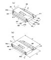
図1は本発明の実施の形態1における電子機器を前面側から見た斜視図であり、図2は同電子機器を背面側から見た斜視図である。本発明の実施の形態1における電子機器は前面側に表示部としてのディスプレイ部と、操作ボタンとを備えた情報端末で、例えば携帯型ナビゲーションシステム(以下、NAVIと称す)などに適用される。本発明の実施の形態では、電子機器としてNAVIを例に挙げ説明する。
(Embodiment 1)
1 is a perspective view of an electronic device according to Embodiment 1 of the present invention as viewed from the front side, and FIG. 2 is a perspective view of the electronic device as viewed from the back side. The electronic device according to Embodiment 1 of the present invention is an information terminal provided with a display unit as a display unit and operation buttons on the front side, and is applied to, for example, a portable navigation system (hereinafter referred to as NAVI). In the embodiment of the present invention, NAVI is taken as an example of electronic equipment.
NAVI100は、樹脂などを成型加工した前面筺体部101と背面筺体部102とにより構成されている。図1に示すように、前面筺体部101には視認情報を表示する表示部である液晶ディスプレイなどのディスプレイ部110と、表示画面のメニュー選択などをして視認情報を制御する制御ボタンである操作ボタン120などが配置され、前面側でNAVI100の全ての操作が可能なように構成されている。さらに、ディスプレイ部110の上部には、NAVI100の携帯性を向上させるために把手130を設けている。
The NAVI 100 includes a
また、背面筺体部102の内部空間には、例えばNAVI100の電源としての電池を内蔵することができるような電池収納部と、記録媒体収納部、および/またはUSBなどの外部機器との接続端子収納部などが設けられている。なお、背面筺体部102には、厚みが薄い薄肉部104、薄肉部104よりも厚肉の厚肉部105、および薄肉部104と厚肉部105とを傾斜面で連設する段差部106を備える。これらの収納部は、背面筺体部102の薄肉部104に設けた蓋部材140や、背面筺体部102から側面部103にかけて設けた蓋部材150によって、防水、防湿あるいは防塵を保つように密閉されている。
In addition, in the internal space of the
一方、これらのNAVI100などの電子機器は、屋内だけでなく野外での使用機会も多いことから、持ち運びや落下などに際して耐振動性、耐衝撃性とともに、周囲環境の温湿度変化などに対する耐環境性を有することが要求されている。近年、NAVI100を始めとする携帯型電子機器は、アウトドアや建設現場などの周囲環境が過酷な条件下で使用される例が増加している。そのため、NAVI100本体である前面筺体部101や背面筺体部102、さらには操作ボタン120などの全ての構成部材に防水、防湿、防塵構造などが要求される。
On the other hand, since these electronic devices such as NAVI100 are used not only indoors but also outdoors, they are resistant to vibrations and shocks when carried and dropped, and are also resistant to changes in ambient temperature and humidity. It is required to have In recent years, portable electronic devices such as the NAVI 100 are increasingly used under conditions where the surrounding environment such as the outdoors or a construction site is severe. Therefore, a waterproof, moistureproof, dustproof structure and the like are required for all components such as the
特に、本発明の実施の形態1のNAVI100における筺体に配置された各収納部は、内部に電極端子などが露出した状態で配置されているため、水滴や埃などの侵入によって電極端子などの腐食や劣化を発生させる。そのため、蓋部材140、150は振動や衝撃に対しても強固に蓋機能を有するとともに、温湿度変化などの耐環境性を備えた確実な防水、防湿、防塵機能を果たすことが要求される。
In particular, each storage unit arranged in the housing of the
本発明の実施の形態1では、背面筺体部102の薄肉部104に収納部を設けた場合を例に説明する。図3は本発明の実施の形態1におけるNAVI100の収納部200、201の構成を示す斜視図であり、図3(a)は長方形形状の開口部210を平坦とした実施例を示す斜視図、図3(b)は長円形の開口部211に段差を設けた実施例を示す斜視図である。
In the first embodiment of the present invention, a case where a storage portion is provided in the
図1、図2および図3(a)、図3(b)に示すように、NAVI100の背面筺体部102の薄肉部104に、これらの収納部200、201などが設けられている。収納部200、201には内部に開口部210、211が設けられて、開口部210、211内にUSBなどの接続端子(図示せず)などが露出して配置されている。蓋部材140は、この収納部200、211を密閉するように構成されている。なお、蓋部材140と収納部200、201との密閉構造については後で詳細に述べる。
As shown in FIGS. 1, 2, 3 (a), and 3 (b), the
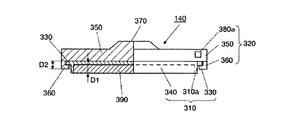
図4は本発明の実施の形態1における蓋部材140の詳細を示す斜視図であり、図4(a)は収納部200に蓋部材140が固定される前の状態を示す図、図4(b)は蓋部材140を収納部200に固定した場合の蓋部材140の状態を示す図である。また、図5は同蓋部材140の図4(b)におけるC−C線断面図である。
4 is a perspective view showing details of the
図4(a)、図4(b)、図5に示すように、蓋部材140は、第1蓋部材である蓋本体310と第2蓋部材である蓋ラッチ320とにより構成されている。本発明の実施の形態1では、蓋本体310と蓋ラッチ320とにより構成される蓋部材140が、全体として略矩形形状を有するように構成された場合について示している。
As shown in FIGS. 4A, 4B, and 5, the
蓋本体310は、その側端部310aに形成された第1係合部となる舌部330と、第1本体となる蓋体340とにより構成されている。さらに、蓋ラッチ320は、蓋本体310の全面を覆うように構成された第2本体となるラッチ部350と、ラッチ部350の両側端部350aに設けられて蓋本体310の舌部330と係合する第2係合部となる鍵部360とを備えている。
The
すなわち、蓋本体310と蓋ラッチ320とは、蓋本体310の側端部310aに設けた舌部330と、蓋ラッチ320の側端部350aに設けた鍵部360の溝とが係合し、蓋本体310の主面上を蓋ラッチ320が図4(a)の矢印A方向に摺動するように所定の隙間を有して嵌め合わされた構成としている。また、蓋ラッチ320のラッチ部350の上面には、蓋ラッチ320を手の指などで摺動させるためのロック爪370が設けられ、このロック爪370によって蓋ラッチ320を蓋本体310上で摺動させることが容易となるように構成されている。
That is, the
また、蓋ラッチ320が矢印A方向に摺動する方向における蓋ラッチ320の端面部380には、突起部380aが設けられている。本発明の実施の形態1では、突起部380aを蓋ラッチ320が摺動する摺動面に対して平行に、端面部380の両側に一対設けた構成としている。
In addition, a
また、図4(b)は蓋ラッチ320が蓋本体310上を矢印Aの方向に摺動し、蓋部材140が収納部200に固定された状態の蓋部材140を示している。このとき、蓋ラッチ320の端面部380は後述の収納部200の端面部250に当接するため、蓋体340の端面部340a(図6参照)と蓋ラッチ320の端面部380とは略同一面となり、蓋ラッチ320に設けた突起部380aが、蓋体340の端面部340aより突出する。
FIG. 4B shows the
一方、図5に示すように、舌部330に鍵部360の溝部に係合した状態において、蓋体340の厚みD1は、蓋ラッチ320の下面から鍵部360の溝部上面までの厚みD2よりも大きくなるように構成し、さらに、蓋体340と蓋ラッチ320との摺動面と反対側の蓋体340の面は空間を備え、その空間にはゴムや樹脂などの弾性部材390を装着している。
On the other hand, as shown in FIG. 5, in a state where the
また、図6は本発明の実施の形態1における蓋部材140の図4(a)におけるB−B線断面図である。図5に示すように、蓋本体310には突起部380aが設けられた蓋ラッチ320が蓋本体310に対して摺動可能に配置されている。また、蓋本体310であって、蓋ラッチ320の突起部380aが設けられた面と反対側の端部には、部材を延伸等の手段により、蓋本体310を構成する蓋体340の肉厚を薄くしたヒンジ部400を設けることで、蓋体340の折り曲げが容易なように構成している。さらに、ヒンジ部400の先端部には、蓋部材140をNAVI100の背面筺体部102における薄肉部104などに取り付け固定する固定部410が設けられている。また、蓋体340と蓋ラッチ320とを摺動させる蓋体340における摺動面と反対側の空間の内部には、ゴムや樹脂などの所定厚みの弾性部材390が蓋体340に接着などによって取り付けられている。なお、このとき、弾性部材390の下端面が蓋体340の周囲面よりも突出するように構成すると、後述するように、例えば蓋本体固定面240に対して確実に圧着でき、防水性能上望ましい。
6 is a cross-sectional view of the
また、図6に示すように、蓋本体310と蓋ラッチ320とが摺動する面には、第1凸部となる凸部430が設けられ、凸部430の両側における蓋本体310と蓋ラッチ320とが摺動する面に凹部420を設けている。一方、蓋ラッチ320の蓋本体310が摺動する面には、凹部420と係合する第2凸部となる凸部440が設けられている。このような構成によれば、蓋ラッチ320を蓋本体310上で摺動させる際に、蓋ラッチ320を摺動させる際の位置決めと、位置決めの際のクリック感を得ることができ、蓋部材140が確実にロックされたことを確認することができる。
As shown in FIG. 6, the surface on which the lid
以下、本発明の実施の形態1における蓋部材140を用いて図3(a)に示す収納部200に蓋をする場合について説明する。図7は、本発明の実施の形態1で述べた蓋部材140により収納部200に蓋をする状態を示す断面図であり、図7(a)は蓋部材140を開放した状態、図7(b)は蓋部材140で収納部200に蓋をした状態を示す。
Hereinafter, the case where the
まず、図3(a)の収納部200の構成についてさらに詳しく説明する。図3(a)に示すように、収納部200には内部に開口部210が設けられて、開口部210内にUSBなどの接続端子や、収納部200に収納した電池などが露出して配置されている。また、収納部200には、蓋本体310の固定部410を固定するためのネジ穴部220を有する固定段差部230と、蓋本体310が嵌り合う蓋本体固定面240が設けられている。さらに、収納部200の固定段差部230と反対側には、蓋体340の端面部340aと蓋ラッチ320の端面部380とが面で当接するように端面部250が設けられている。また、端面部250には、蓋部材140の蓋ラッチ320に設けた突起部380aが嵌り合って係合する係合孔250aを、それぞれの突起部380aの位置に対応して設けている。
First, the configuration of the
すなわち、本発明の実施の形態1では、蓋部材140が、全体として略矩形形状を有するように構成された場合について述べており、収納部200は全体として矩形形状の凹部を形成して、その凹部に蓋部材140が嵌り合う構成としている。したがって、図4(b)に示す蓋部材140の長さL1と図3(a)に示す凹部の長さL2とを略等しくするとともに、図4(b)に示す蓋部材140の幅L3と図3(a)に示す凹部の幅L4とを略等しくなるように構成している。
That is, in Embodiment 1 of the present invention, the case where the
図7(a)に示すように、蓋部材140の蓋本体310の固定部410が、収納部200の固定段差部230に取り付け部材610を介してネジ620などによって固定されている。また、この状態では、蓋本体310のヒンジ部400が折り曲げられて、蓋部材140と収納部200との密閉が開放され、収納部200の開口部210内の接続端子(図示せず)などにUSBなどの外部端子を接続可能な状態としている。
As shown in FIG. 7A, the fixing
このとき、蓋部材140の蓋ラッチ320は蓋本体310に対して矢印Dの方向に摺動
させられた状態となっている。
At this time, the
一方、図7(b)は蓋部材140によって収納部200が閉じられた状態を示している。すなわち、蓋部材140が収納部200の開口部210側に押圧されて、蓋部材140が収納部200に嵌り合い、蓋本体310の弾性部材390が蓋本体固定面240に当接した状態となる。
On the other hand, FIG. 7B shows a state in which the
この状態で、蓋ラッチ320のロック爪370によって蓋ラッチ320を矢印Eの方向に移動させる。このとき、蓋ラッチ320の鍵部360が蓋本体310の舌部330に案内されて摺動するとともに、蓋本体310上を摺動して蓋ラッチ320を矢印E方向に容易に摺動させることができる。
In this state, the
この結果、蓋ラッチ320に設けた突起部380aが、収納部200の端面部250に設けた係合孔250aに嵌り込み、蓋部材140の蓋ラッチ320を収納部200に固定することとなる。このとき、蓋部材140の全体を押さえ込みながら、なおかつ、弾性部材390を変形させながら蓋ラッチ320を摺動させることができる。そのため、係合孔250aの垂直方向の位置を突起部380aの位置より少し低くした状態でも両者を係合させることができる。その結果、突起部380aが係合孔250aに係合した後には、弾性部材390の弾性力を利用して蓋本体固定面240と弾性部材390との密閉力を高め、蓋部材140と収納部200との結合を強固にすることができる。
As a result, the
そのため、振動や落下などの衝撃がNAVI100に加わった場合でも、収納部200と蓋部材140との係合が外れることがなく、確実な密閉機能を確保することができる。
Therefore, even when an impact such as vibration or dropping is applied to the
このように、本発明の実施の形態1における蓋部材140によれば、蓋部材140のうちの蓋本体310に設けた舌部330を、蓋ラッチ320に設けた鍵部360の溝部が抱え込み、蓋ラッチ320で蓋本体310を均一に押圧することが可能となる。そのために、蓋本体310の弾性部材390によって、開口部210の全領域を均一に密閉することが可能となり、極めて防水、防湿、防塵性能に優れた蓋部材140を有するNAVI100を実現することができる。
Thus, according to the
さらに、このような抱え込み構造を、蓋本体310と蓋ラッチ320のそれぞれの両端部に設けた舌部330と鍵部360とにより係合する構成としており、極めて少ない部品点数で実現することができる。
Further, such a holding structure is configured to be engaged by the
また、蓋ラッチ320に設けた突起部380aとNAVI100の背面筺体部102に設けた係合孔250aとを係合させているため、振動や落下などの衝撃に強く、蓋部材140の係合が簡単に外れることのない、確実なロック機能を確保することができる。
In addition, since the
さらに、蓋本体310と蓋ラッチ320は摺動が可能なように所定の隙間を有して構成されている。そのため、蓋本体310の蓋体340と蓋ラッチ320との構成材料が異なる場合でも、周囲環境の温湿度変化などによるそれぞれの膨張収縮の影響を受けることがない。その結果、収納部200と蓋部材140との密閉開閉動作を確実に行うことができる。
Further, the
さらに、本発明の実施の形態1におけるNAVI100では、蓋体340の厚みD1を舌部330に鍵部360が係止した状態の厚みD2よりも大きくなるように構成し、さらに、蓋体340の蓋ラッチ320が摺動する面と反対側の面には、ゴムや樹脂などの弾性部材390を装着している。そのため、弾性部材390をNAVI100に設けた開口部210を形成した蓋本体固定面240に確実に当接させて、確実な密閉機能を発現することができる。
Further, in the
次に、図3(b)の収納部201の構成について説明する。図3(b)に示す収納部201の構成は、以下の構成が図3(a)に示す収納部200の構成と異なる。すなわち、開口部211を長円形の形状とし、その周囲に、蓋本体固定面241よりも突出させて弾性部材390と密着させるための弾性部材固定段差部260を形成している。さらに、蓋本体固定面241の両側には、蓋ラッチ320の鍵部360の底面部が摺動するラッチ摺動段差部270を設けている。なお、蓋ラッチ320の端面部380に設けた突起部380aが嵌り合って係合する係合孔250aなどの構成は図3(a)に示す構成と同様である。
Next, the configuration of the
このような構成によれば、蓋ラッチ320が蓋本体310上を摺動する際に、蓋ラッチ320の鍵部360の底面部をラッチ摺動段差部270に沿わせて確実に摺動させることができるとともに、開口部211周囲に設けた弾性部材固定段差部260によって弾性部材390との密着をより強固にすることができる。
According to such a configuration, when the
なお、本発明の実施の形態1では開口部211を長円形状とし、その周囲に弾性部材固定段差部260を形成しているが、開口部211の形状が必ずしも長円形状である必要はなく、矩形、円形などとして弾性部材固定段差部260を形成しても良い。
In the first embodiment of the present invention, the
また、弾性部材固定段差部260を備えることで、蓋体340と蓋ラッチ320との摺動面と反対側の蓋体340に備える空間に有する弾性部材390による密着性をより向上させることができる。この弾性部材固定段差部260は、蓋本体固定面241と同じ樹脂材料や、封止性があるゴム等のエラストマー性の材料を適用することができる。
Further, by providing the elastic
また、図3(b)では蓋本体固定面241における端面部250と対向する端面部242よりもラッチ摺動段差部270に端面部270aを突出させた構成であるが、端面部270aは蓋本体固定面241と端面部250との間に形成しても適用できる。しかしながら、蓋本体固定面241の端面部242と端面部270aとの間に空隙が生じ易くなるため、防水性能の観点からは端面部250に蓋本体固定面241を介して対向する端面部243と蓋本体固定面241の端面部242との間に備えることが好ましい。
Further, in FIG. 3B, the
なお、上述の蓋部材140を構成する蓋本体310や蓋ラッチ320は、樹脂の成型によって容易に形成することが可能である。このとき、蓋本体310には弾性を有する樹脂材料を用い、蓋本体310を抱え込む蓋ラッチ320には剛性を有する材料を用いると蓋部材140としてはより望ましい構成とすることができる。
The
(実施の形態2)
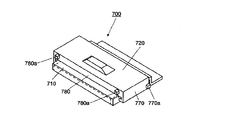
図8は、本発明の実施の形態2における蓋部材700の詳細を示す斜視図であり、図9は、本発明の実施の形態2におけるNAVI100の収納部202の構成を示す斜視図である。図8に示すように、本発明の実施の形態2における蓋部材700の基本構成は、図4(a)、図4(b)における実施の形態1と同様であるが、実施の形態2では、収納部202が図1および図2における蓋部材150の位置に備える点と、蓋ラッチ720の構成の点とが異なる。
(Embodiment 2)
FIG. 8 is a perspective view illustrating details of the
すなわち、図8に示すように、本発明の実施の形態2における蓋部材700では、蓋ラッチ720の蓋ラッチ720が摺動する方向の端面部780に設けた2個の突起部780aに加え、蓋ラッチ720が蓋本体710と摺動する摺動方向に対して直交する両側の端面部770に、第2突起部770aを設けている。さらに、蓋ラッチ720において、突起部780aと第2突起部770aとは、蓋ラッチ720の面の対角線に近くなる位置に設けている。
That is, as shown in FIG. 8, in the
また、このような蓋部材700が嵌り込む収納部202は、その基本構成は実施の形態1における図3(b)に示す構成と同様であるが、ラッチ摺動段差部270の両側で第2突起部770aと対応する位置に係合溝280が付加されて形成されている。
Further, the
このような蓋部材700と収納部202との構成によれば、蓋部材700によって収納部202を密閉する際に、蓋ラッチ720の突起部780aと収納部202の係合孔250aと係合し、さらに、蓋ラッチ720の第2突起部770aと収納部202の係合溝280とを係合させて、蓋ラッチ720の4隅と収納部202の4隅とを互いに強固に固定することができる。その結果、蓋ラッチ720で蓋本体710を抱え込みながら蓋本体710によって収納部202の開口部211の全領域を均一に密閉することが可能となる。
According to such a configuration of the
また、このようにNAVI100と蓋部材700との固定箇所が増えることにより、NAVI100に加わる衝撃などに対してより強固な固定を実現することができる。その結果、衝撃が印加される環境条件下でも、蓋部材700としての防水、防湿、防塵機能などをさらに確実に発現することが可能となる。
In addition, by increasing the number of fixing points between the
なお、突起部780aや第2突起部770aの形状は任意に設定可能であるが、蓋部材700の開閉の自由度などを考慮すれば、収納部202に設けた係合孔250aや係合溝280との接触面積ができるだけ大きくなるようにすることが望ましい。
The shapes of the
また、突起部780aや第2突起部770aの形状としては、係合孔250aや係合溝280に嵌り込む方向に先端部を有するテーパ形状としてもよく、さらに、係合孔250aや係合溝280もテーパ形状としてもよい。
Further, the shape of the projecting
(実施の形態3)
図10、図11、図12は本発明の実施の形態3における蓋部材800とそれを用いたNAVI100の収納部900の構成を示す斜視図である。図10は本発明の実施の形態3における蓋部材800の構成を示す斜視図、図11は本発明の実施の形態3におけるNAVI100の収納部900の構成を示す斜視図、図12は本発明の実施の形態3における蓋部材800によって収納部900に蓋をした状態を示す斜視図である。
(Embodiment 3)
10, 11 and 12 are perspective views showing the configuration of the lid member 800 and the
本発明の実施の形態3における蓋部材150と収納部900とは、特に図1、図2に示すように、NAVI100の背面筺体部102の厚肉部105から側面部103にかけて設ける構成や、薄肉部104から側面部103にかけて設ける構成の場合に好適であるが、本発明の実施の形態3としては、厚肉部105から側面部103にかけて設けた蓋部材150を例に挙げ説明する。なお、収納部としてはUSB端子などの接続端子収納部やNAVI100の電源に適用される電池収納部などに好適である。
As shown in FIGS. 1 and 2, the
本発明の実施の形態3における蓋部材150の基本構成は実施の形態1および実施の形態2と同様であるが次の点が異なる。すなわち、蓋部材150の蓋本体810を、NAVI100の筺体へ固定する固定部の構成が異なる。図10に示すように、蓋ラッチ820の蓋ラッチ820の突起部830aが設けられた端面部830と反対側には、蓋ラッチ820から延伸し、NAVI100の、例えば側面部103の形状に沿った形状に折り曲げられたカバー部840が設けられている。また、蓋本体810の固定部850も、蓋本体810から延伸して設けられ、蓋ラッチ820の内側になるように折り曲げられて形成されている。
The basic configuration of the
一方、図11には、このような蓋部材800で蓋をする収納部900の構成を示す。基本構成は実施の形態1で述べた図3(b)と同様であり、蓋部材150を固定する固定段差部910が、開口部920が形成された蓋本体固定面930に対して略直角に形成されている点が異なる。なお、端面部940に形成された係合孔940aは、蓋部材150を収納部900に固定して蓋をしたときに、突起部830aが係合される位置に設けられている。
On the other hand, FIG. 11 shows a configuration of a
図12は、以上のように構成した蓋部材150を収納部900に固定して蓋をし、蓋ラッチ820の突起部830aを蓋本体810の係合孔940aに嵌め合わせて係合した状態を示している。このとき、固定段差部910に固定された蓋本体810の固定部850を覆い隠す第2カバー部950をさらに設けている。
FIG. 12 shows a state in which the
本発明の実施の形態3における蓋部材150によれば、蓋本体810と蓋ラッチ820を、図1、図2の背面筺体部102のコーナー部に沿わせる形状として、蓋部材150とNAVI100の筺体との一体感を得ることが容易となり、蓋機能としての密閉機能を確保するとともに、見栄えの優れたNAVI100を提供することができるものである。
According to the
なお、このような本発明の実施の形態における蓋部材は、樹脂材料の成型のみによって容易に実現することができる。そのため、樹脂材料の有する弾性力を利用することによっても開口部と蓋本体との密閉性を確保するとともに、突起部と筺体に設けた係合孔とを弾性的に固定し、耐衝撃性や温度変化などの耐環境性に優れた蓋部材を実現できるものである。 Note that the lid member in the embodiment of the present invention can be easily realized only by molding a resin material. Therefore, by utilizing the elastic force of the resin material, the sealing between the opening and the lid main body is secured, and the protrusion and the engagement hole provided in the housing are elastically fixed, and the impact resistance and A lid member excellent in environmental resistance such as temperature change can be realized.
なお、本発明の実施の形態では、電子機器としてNAVIを対象として説明したが、NAVI以外でもPDA、ゲーム機、携帯電話、看護機器、ノートパソコン、カメラなどの電子機器にも適用できる。 In the embodiment of the present invention, NAVI is described as an electronic device. However, the present invention can be applied to electronic devices such as PDAs, game machines, mobile phones, nursing devices, laptop computers, and cameras other than NAVI.
本発明によれば、周囲環境の温湿度変化などによるそれぞれの膨張収縮の影響を受けることなく、なおかつ開口部全面を均一に押圧して蓋をする蓋部材を用いた電子機器であるため、特に携帯型の情報機器などに有用である。 According to the present invention, since it is an electronic device using a lid member that is not affected by each expansion and contraction due to changes in temperature and humidity of the surrounding environment and that uniformly presses the entire opening and covers it, Useful for portable information devices.
100 NAVI
101 前面筺体部
102 背面筺体部
103 側面部
104 薄肉部
105 厚肉部
106 段差部
110 ディスプレイ部
120 操作ボタン
130 把手
140,150,700,800 蓋部材
200,201,202,900 収納部
210,211,920 開口部
220 ネジ穴部
230,910 固定段差部
240,241,930 蓋本体固定面
242,243,250,270a,340a,380,770,780,830,940 端面部
250a,940a 係合孔
260 弾性部材固定段差部
270 ラッチ摺動段差部
280 係合溝
310,710,810 蓋本体
310a,350a 側端部
320,720,820 蓋ラッチ
330 舌部
340 蓋体
350 ラッチ部
360 鍵部
370 ロック爪
380a,780a,830a 突起部
390 弾性部材
400 ヒンジ部
410,850 固定部
420 凹部
430,440 凸部
610 取り付け部材
620 ネジ
770a 第2突起部
840 カバー部
950 第2カバー部
100 NAVI
DESCRIPTION OF
Claims (5)
前記蓋部材は、
第1蓋部材と、
前記第1蓋部材の面上を、前記筐体部に固定された第1蓋部材の一つの端部と、該端部とは反対側の第1蓋部材の端部との間の向きに、摺動する第2蓋部材と、
を有し、
前記第1蓋部材は、前記面における、前記第2蓋部材の摺動方向に直交する向きに対向する両端部に、前記第2蓋部材に摺動可能に抱え込まれることで係合する第1係合部を有し、
前記第2蓋部材は、前記第1の係合部の前記面の左右端部を抱え込むことで前記第1蓋部材と摺動可能に係合する第2係合部を有し、
前記第2蓋部材に形成された突起が、前記第2蓋部材が摺動した際に前記筐体部に係合することで、前記第2蓋部材が前記筐体部に固定され、
前記第2蓋部材が前記筐体部に固定された状態で、前記蓋部材が前記収納部に押圧され、前記蓋部材が前記開口部を閉じ、
前記第1蓋部材と前記筐体部との間に、前記蓋部材が前記収納部に押圧された状態で弾性変形する弾性部材を備えた、電子機器。 A housing part having a housing part and an opening formed inside the housing part; and a lid member for opening and closing the housing part and the opening part of the housing part,
The lid member is
A first lid member;
On the surface of the first lid member, in a direction between one end portion of the first lid member fixed to the housing portion and the end portion of the first lid member opposite to the end portion. A sliding second lid member ;
Have
The first lid member engages by being slidably held by the second lid member at both ends of the surface facing in a direction orthogonal to the sliding direction of the second lid member. Having an engaging portion,
The second lid member has a second engagement portion that slidably engages with the first lid member by holding right and left end portions of the surface of the first engagement portion ,
When the projection formed on the second lid member engages with the casing when the second lid member slides, the second lid member is fixed to the casing.
In a state where the second lid member is fixed to the housing portion, the lid member is pressed against the storage portion, and the lid member closes the opening,
An electronic apparatus comprising an elastic member between the first lid member and the housing portion that is elastically deformed in a state where the lid member is pressed by the storage portion.
Priority Applications (1)
| Application Number | Priority Date | Filing Date | Title |
|---|---|---|---|
| JP2013264839A JP5909655B2 (en) | 2008-03-03 | 2013-12-24 | Electronics |
Applications Claiming Priority (3)
| Application Number | Priority Date | Filing Date | Title |
|---|---|---|---|
| JP2008051780 | 2008-03-03 | ||
| JP2008051780 | 2008-03-03 | ||
| JP2013264839A JP5909655B2 (en) | 2008-03-03 | 2013-12-24 | Electronics |
Related Parent Applications (1)
| Application Number | Title | Priority Date | Filing Date |
|---|---|---|---|
| JP2009022146A Division JP5444741B2 (en) | 2008-03-03 | 2009-02-03 | Electronics |
Publications (2)
| Publication Number | Publication Date |
|---|---|
| JP2014063758A JP2014063758A (en) | 2014-04-10 |
| JP5909655B2 true JP5909655B2 (en) | 2016-04-27 |
Family
ID=40637014
Family Applications (2)
| Application Number | Title | Priority Date | Filing Date |
|---|---|---|---|
| JP2009022146A Active JP5444741B2 (en) | 2008-03-03 | 2009-02-03 | Electronics |
| JP2013264839A Active JP5909655B2 (en) | 2008-03-03 | 2013-12-24 | Electronics |
Family Applications Before (1)
| Application Number | Title | Priority Date | Filing Date |
|---|---|---|---|
| JP2009022146A Active JP5444741B2 (en) | 2008-03-03 | 2009-02-03 | Electronics |
Country Status (3)
| Country | Link |
|---|---|
| US (3) | US8045323B2 (en) |
| EP (1) | EP2099271B1 (en) |
| JP (2) | JP5444741B2 (en) |
Families Citing this family (49)
| Publication number | Priority date | Publication date | Assignee | Title |
|---|---|---|---|---|
| JP5444741B2 (en) | 2008-03-03 | 2014-03-19 | パナソニック株式会社 | Electronics |
| US8625305B2 (en) * | 2008-10-31 | 2014-01-07 | Kyocera Corporation | Portable electric device |
| JP5513168B2 (en) | 2010-02-26 | 2014-06-04 | パナソニック株式会社 | Electronics |
| JP5623999B2 (en) * | 2010-08-31 | 2014-11-12 | パナソニック株式会社 | Electronic equipment |
| JP5681894B2 (en) | 2010-08-31 | 2015-03-11 | パナソニックIpマネジメント株式会社 | Electronic equipment |
| USD666981S1 (en) * | 2011-04-06 | 2012-09-11 | Sony Ericsson Mobile Communications Ab | Mobile phone |
| WO2012157414A1 (en) * | 2011-05-16 | 2012-11-22 | Necカシオモバイルコミュニケーションズ株式会社 | Waterproof structure, electronic device, and waterproofing method |
| EP3982210A1 (en) * | 2011-05-20 | 2022-04-13 | Ecolab USA Inc. | Controller |
| JP5906474B2 (en) * | 2011-08-19 | 2016-04-20 | パナソニックIpマネジメント株式会社 | Electronics |
| JP5950258B2 (en) * | 2011-08-19 | 2016-07-13 | パナソニックIpマネジメント株式会社 | Electronics |
| US9795044B2 (en) | 2011-08-22 | 2017-10-17 | Catalyst Lifestyle Limited | Waterproof case |
| HUE064666T2 (en) | 2011-08-22 | 2024-04-28 | Catalyst Lifestyle Ltd | Waterproof case |
| TWI446858B (en) * | 2011-11-02 | 2014-07-21 | Pegatron Corp | Protective cover and electronic device using the same |
| JP5476405B2 (en) * | 2012-02-28 | 2014-04-23 | 東芝テック株式会社 | Electronics |
| CN102785829B (en) * | 2012-09-04 | 2014-11-05 | 上海鸿研物流技术有限公司 | Cover device and container for covering built-in valve mounting passage opening in composite type midsize bulk container |
| USD711872S1 (en) * | 2013-03-15 | 2014-08-26 | Samsung Electronics Co., Ltd. | Electronic device |
| CN104122938B (en) * | 2013-04-23 | 2019-05-24 | 神讯电脑(昆山)有限公司 | Bolting structure |
| JP6221448B2 (en) * | 2013-07-18 | 2017-11-01 | 富士通株式会社 | Lid structure and electronic equipment |
| CN104750196B (en) * | 2013-12-27 | 2018-11-06 | 神讯电脑(昆山)有限公司 | Waterproof knocker and its automatic pressure-regulating type plug member group |
| CN105830546B (en) * | 2013-12-25 | 2019-10-18 | 松下知识产权经营株式会社 | Electronic equipment |
| JP6369815B2 (en) | 2013-12-25 | 2018-08-08 | パナソニックIpマネジメント株式会社 | Electronics |
| CN105830249B (en) * | 2013-12-25 | 2019-02-19 | 松下知识产权经营株式会社 | Shell, the electronic equipment of electronic equipment |
| EP3092878B1 (en) * | 2014-01-07 | 2021-11-10 | Catalyst Lifestyle Limited | Waterproof case |
| USD753077S1 (en) * | 2014-09-24 | 2016-04-05 | Panasonic Avionics Corporation | Display system for seatback mounting |
| CN105578806B (en) * | 2014-10-10 | 2019-02-26 | 神讯电脑(昆山)有限公司 | Single-piece water door |
| JP6047133B2 (en) * | 2014-10-29 | 2016-12-21 | 京セラ株式会社 | Terminal cover and electronic equipment |
| US10088865B1 (en) * | 2014-11-06 | 2018-10-02 | Amazon Technologies, Inc. | Modular computing system |
| WO2016103615A1 (en) * | 2014-12-26 | 2016-06-30 | パナソニックIpマネジメント株式会社 | Lid opening and closing mechanism, electronic device |
| WO2017077670A1 (en) * | 2015-11-06 | 2017-05-11 | パナソニックIpマネジメント株式会社 | Electronic device |
| JP6924931B2 (en) * | 2015-11-06 | 2021-08-25 | パナソニックIpマネジメント株式会社 | Electronic devices and terminal covers for electronic devices |
| CN108496414B (en) * | 2016-11-18 | 2020-01-03 | 三菱电机株式会社 | Terminal protection structure for electronic device and electronic device |
| CN113568479A (en) * | 2017-02-24 | 2021-10-29 | 松下知识产权经营株式会社 | Electronic device |
| USD924236S1 (en) | 2018-01-19 | 2021-07-06 | Panasonic Avionics Corporation | Display system for mounting in a cabin |
| KR102039328B1 (en) * | 2018-02-19 | 2019-11-01 | 엘에스산전 주식회사 | Electronic device having protection structure for components |
| CN109218938B (en) * | 2018-08-13 | 2023-11-14 | 歌尔股份有限公司 | terminal device |
| USD924863S1 (en) | 2018-09-11 | 2021-07-13 | Catalyst Lifestyle Limited | Phone case |
| USD984425S1 (en) | 2018-09-11 | 2023-04-25 | Catalyst Lifestyle Limited | Mobile phone protection case |
| USD903685S1 (en) | 2019-03-29 | 2020-12-01 | Catalyst Lifestyle Limited | Electronic case |
| USD958146S1 (en) | 2019-06-20 | 2022-07-19 | Catalyst Lifestyle Limited | Case for electronic device |
| USD974330S1 (en) | 2019-06-26 | 2023-01-03 | Catalyst Lifestyle Limited | Case for electronic device |
| USD933075S1 (en) | 2019-06-26 | 2021-10-12 | Catalyst Lifestyle Limited | Case for a mobile communication device |
| US11076028B2 (en) | 2019-08-30 | 2021-07-27 | Catalyst Lifestyle Limited | Switch assembly for engaging a switch of an electronic device |
| USD931845S1 (en) | 2020-02-11 | 2021-09-28 | Catalyst Lifestyle Limited | Case for electronic communications device |
| USD932479S1 (en) | 2020-02-11 | 2021-10-05 | Catalyst Lifestyle Limited | Case for electronic communications device |
| USD942438S1 (en) | 2020-02-28 | 2022-02-01 | Catalyst Lifestyle Limited | Bumper for electronic communications device |
| USD984449S1 (en) | 2020-02-28 | 2023-04-25 | Catalyst Lifestyle Limited | Case for electronic device |
| USD941297S1 (en) | 2020-02-28 | 2022-01-18 | Catalyst Lifestyle Limited | Bumper for electronic device |
| US11983044B2 (en) * | 2020-06-02 | 2024-05-14 | Getac Holdings Corporation | Mobile electronic device and expansion unit |
| CN114679865B (en) * | 2021-08-09 | 2024-05-14 | 神基投资控股股份有限公司 | Electronic device and assembling method thereof |
Family Cites Families (26)
| Publication number | Priority date | Publication date | Assignee | Title |
|---|---|---|---|---|
| US5002184A (en) * | 1989-06-12 | 1991-03-26 | Grid Systems Corporation | Soft case protection for a hand held computer |
| US5155659A (en) * | 1991-03-15 | 1992-10-13 | Kunert Steven R | Hand-held data collection terminal with battery compartment sealing lid and lid-tethering hand strap |
| JP3237376B2 (en) | 1994-02-19 | 2001-12-10 | ソニー株式会社 | Lid opening and closing mechanism |
| US5484063A (en) * | 1994-04-13 | 1996-01-16 | Maxtor Corporation | HDD carrying case |
| JP2674537B2 (en) * | 1994-11-30 | 1997-11-12 | 日本電気株式会社 | Electronic equipment housing |
| US5786106A (en) * | 1996-06-24 | 1998-07-28 | Armani; Shane | Battery pack with interchangeable tag-along supplemental feature cartridge particularly for cellular telephones |
| JP3088300B2 (en) * | 1996-08-27 | 2000-09-18 | 静岡日本電気株式会社 | Battery housing structure for electronic equipment |
| US5963422A (en) * | 1997-06-30 | 1999-10-05 | Lsi Logic Corporation | Systems and methods for releaseably securing an article within a computer system |
| JP3496493B2 (en) * | 1997-12-18 | 2004-02-09 | 双葉電子工業株式会社 | Mounting structure of waterproof battery lid |
| JP3794844B2 (en) * | 1998-11-30 | 2006-07-12 | 松下電器産業株式会社 | Portable radio |
| JP2001021979A (en) | 1999-07-09 | 2001-01-26 | Canon Inc | Waterproof mechanism for electronic equipment |
| JP4337261B2 (en) | 2000-12-06 | 2009-09-30 | 日本電気株式会社 | Mobile phone |
| JP2003142841A (en) * | 2001-11-02 | 2003-05-16 | Olympus Optical Co Ltd | Cell lid structure and recording medium lid structure |
| US7325846B2 (en) * | 2003-05-07 | 2008-02-05 | Hewlett-Packard Development Company, L.P. | Low profile mechanical assist hood latch |
| TW587845U (en) * | 2003-05-09 | 2004-05-11 | Hon Hai Prec Ind Co Ltd | Battery cover for a communication unit |
| JP3928967B2 (en) | 2004-06-02 | 2007-06-13 | 株式会社創成電子 | Electronic device having a storage portion and a waterproof detachable lid covering the opening |
| TW200602843A (en) * | 2004-07-09 | 2006-01-16 | Mitac Technology Corp | Cover mechanism for interface slot surface in notebook |
| JP4761796B2 (en) * | 2005-03-11 | 2011-08-31 | 三洋電機株式会社 | Electrical equipment with a lid |
| CN2792102Y (en) * | 2005-04-15 | 2006-06-28 | 鸿富锦精密工业(深圳)有限公司 | Cover plate fixing device combination |
| ATE364865T1 (en) * | 2005-10-07 | 2007-07-15 | Research In Motion Ltd | EXPANDABLE BATTERY COMPARTMENT FOR PORTABLE ELECTRONIC DEVICES |
| JP2007157663A (en) * | 2005-12-08 | 2007-06-21 | Eastman Kodak Co | Battery storage device |
| JP2008004348A (en) * | 2006-06-21 | 2008-01-10 | Nikon Corp | Lid |
| TW200847891A (en) * | 2007-05-25 | 2008-12-01 | Mitac Technology Corp | Movable engaging door structure |
| US20090008947A1 (en) * | 2007-07-06 | 2009-01-08 | Hsiang-Chi Chien | Slide Latch |
| US7735197B2 (en) * | 2007-09-14 | 2010-06-15 | Cheng Uei Precision Industry Co., Ltd. | Hinge for circumrotatory location |
| JP5444741B2 (en) | 2008-03-03 | 2014-03-19 | パナソニック株式会社 | Electronics |
-
2009
- 2009-02-03 JP JP2009022146A patent/JP5444741B2/en active Active
- 2009-03-02 EP EP09154099.7A patent/EP2099271B1/en active Active
- 2009-03-03 US US12/396,677 patent/US8045323B2/en active Active
-
2011
- 2011-06-28 US US13/170,521 patent/US8611073B2/en active Active
-
2013
- 2013-06-27 US US13/928,772 patent/US9161467B2/en active Active
- 2013-12-24 JP JP2013264839A patent/JP5909655B2/en active Active
Also Published As
| Publication number | Publication date |
|---|---|
| EP2099271B1 (en) | 2017-07-26 |
| EP2099271A2 (en) | 2009-09-09 |
| EP2099271A3 (en) | 2010-07-14 |
| US20130286569A1 (en) | 2013-10-31 |
| US20110255229A1 (en) | 2011-10-20 |
| JP5444741B2 (en) | 2014-03-19 |
| US20090219676A1 (en) | 2009-09-03 |
| JP2014063758A (en) | 2014-04-10 |
| US8611073B2 (en) | 2013-12-17 |
| JP2009238735A (en) | 2009-10-15 |
| US8045323B2 (en) | 2011-10-25 |
| US9161467B2 (en) | 2015-10-13 |
Similar Documents
| Publication | Publication Date | Title |
|---|---|---|
| JP5909655B2 (en) | Electronics | |
| JP2009238735A5 (en) | ||
| US9317077B2 (en) | Electronic device provided with cover | |
| JP5950258B2 (en) | Electronics | |
| US8112129B2 (en) | Seal structure, electronic apparatus, and sealing method | |
| US7505215B2 (en) | Camera module and electronic apparatus | |
| US8014139B2 (en) | Compact and light computer casing structure | |
| US9338910B2 (en) | Electronic device and sealed structure | |
| WO2010131307A1 (en) | Portable terminal device | |
| JP6861343B2 (en) | Electronics | |
| JP2011239099A (en) | Waterproof apparatus and electronic equipment | |
| US9040818B2 (en) | Dust-proof mechanism and electronic device using the same | |
| JP4473104B2 (en) | Cover seal structure | |
| JP5482443B2 (en) | Case structure for portable electronic devices | |
| US8254099B2 (en) | Housing of portable electronic device | |
| JP2011259279A (en) | Portable electronic device | |
| JP6507017B2 (en) | Electronics | |
| US9128675B2 (en) | Electronic device | |
| US9232032B2 (en) | Electronic device and communication device | |
| JP6691300B2 (en) | Electronic device having reinforcing member | |
| KR20230148062A (en) | Electronic device including guide member for wiring | |
| JP4659639B2 (en) | Mobile device | |
| KR20100004302U (en) | Case for portable electronic product |
Legal Events
| Date | Code | Title | Description |
|---|---|---|---|
| RD01 | Notification of change of attorney |
Free format text: JAPANESE INTERMEDIATE CODE: A7421 Effective date: 20140115 |
|
| RD01 | Notification of change of attorney |
Free format text: JAPANESE INTERMEDIATE CODE: A7421 Effective date: 20140418 |
|
| A711 | Notification of change in applicant |
Free format text: JAPANESE INTERMEDIATE CODE: A711 Effective date: 20141007 |
|
| A977 | Report on retrieval |
Free format text: JAPANESE INTERMEDIATE CODE: A971007 Effective date: 20141126 |
|
| A131 | Notification of reasons for refusal |
Free format text: JAPANESE INTERMEDIATE CODE: A131 Effective date: 20141202 |
|
| A521 | Request for written amendment filed |
Free format text: JAPANESE INTERMEDIATE CODE: A523 Effective date: 20150123 |
|
| A131 | Notification of reasons for refusal |
Free format text: JAPANESE INTERMEDIATE CODE: A131 Effective date: 20150630 |
|
| A521 | Request for written amendment filed |
Free format text: JAPANESE INTERMEDIATE CODE: A523 Effective date: 20150730 |
|
| TRDD | Decision of grant or rejection written | ||
| A01 | Written decision to grant a patent or to grant a registration (utility model) |
Free format text: JAPANESE INTERMEDIATE CODE: A01 Effective date: 20160105 |
|
| A61 | First payment of annual fees (during grant procedure) |
Free format text: JAPANESE INTERMEDIATE CODE: A61 Effective date: 20160118 |
|
| R151 | Written notification of patent or utility model registration |
Ref document number: 5909655 Country of ref document: JP Free format text: JAPANESE INTERMEDIATE CODE: R151 |