JP5906247B2 - Oxygen separator and method - Google Patents
Oxygen separator and method Download PDFInfo
- Publication number
- JP5906247B2 JP5906247B2 JP2013534432A JP2013534432A JP5906247B2 JP 5906247 B2 JP5906247 B2 JP 5906247B2 JP 2013534432 A JP2013534432 A JP 2013534432A JP 2013534432 A JP2013534432 A JP 2013534432A JP 5906247 B2 JP5906247 B2 JP 5906247B2
- Authority
- JP
- Japan
- Prior art keywords
- oxygen
- electrode
- membrane
- unit
- containing gas
- Prior art date
- Legal status (The legal status is an assumption and is not a legal conclusion. Google has not performed a legal analysis and makes no representation as to the accuracy of the status listed.)
- Expired - Fee Related
Links
- QVGXLLKOCUKJST-UHFFFAOYSA-N atomic oxygen Chemical compound [O] QVGXLLKOCUKJST-UHFFFAOYSA-N 0.000 title claims description 134
- 239000001301 oxygen Substances 0.000 title claims description 134
- 229910052760 oxygen Inorganic materials 0.000 title claims description 134
- 238000000034 method Methods 0.000 title claims description 21
- 239000012528 membrane Substances 0.000 claims description 126
- 239000007789 gas Substances 0.000 claims description 64
- 239000000758 substrate Substances 0.000 claims description 56
- 239000011148 porous material Substances 0.000 claims description 41
- 239000000463 material Substances 0.000 claims description 13
- 230000004888 barrier function Effects 0.000 claims description 10
- 238000010438 heat treatment Methods 0.000 claims description 10
- 238000011144 upstream manufacturing Methods 0.000 claims description 10
- 238000001816 cooling Methods 0.000 claims description 6
- 230000004907 flux Effects 0.000 claims description 4
- WUKWITHWXAAZEY-UHFFFAOYSA-L calcium difluoride Chemical compound [F-].[F-].[Ca+2] WUKWITHWXAAZEY-UHFFFAOYSA-L 0.000 claims description 3
- 238000004891 communication Methods 0.000 claims description 3
- 239000013078 crystal Substances 0.000 claims description 3
- 239000012530 fluid Substances 0.000 claims description 3
- 239000010436 fluorite Substances 0.000 claims description 3
- 239000010410 layer Substances 0.000 description 57
- 239000003570 air Substances 0.000 description 23
- XEEYBQQBJWHFJM-UHFFFAOYSA-N iron Substances [Fe] XEEYBQQBJWHFJM-UHFFFAOYSA-N 0.000 description 16
- 239000010408 film Substances 0.000 description 14
- 238000000926 separation method Methods 0.000 description 14
- 150000001875 compounds Chemical class 0.000 description 10
- 238000004519 manufacturing process Methods 0.000 description 9
- 239000011651 chromium Substances 0.000 description 8
- IJGRMHOSHXDMSA-UHFFFAOYSA-N Atomic nitrogen Chemical compound N#N IJGRMHOSHXDMSA-UHFFFAOYSA-N 0.000 description 7
- RTAQQCXQSZGOHL-UHFFFAOYSA-N Titanium Chemical compound [Ti] RTAQQCXQSZGOHL-UHFFFAOYSA-N 0.000 description 7
- 239000011521 glass Substances 0.000 description 7
- 239000010936 titanium Substances 0.000 description 7
- MYMOFIZGZYHOMD-UHFFFAOYSA-N Dioxygen Chemical compound O=O MYMOFIZGZYHOMD-UHFFFAOYSA-N 0.000 description 6
- 230000008901 benefit Effects 0.000 description 6
- 238000000151 deposition Methods 0.000 description 6
- 229910052758 niobium Inorganic materials 0.000 description 6
- 239000010955 niobium Substances 0.000 description 6
- GUCVJGMIXFAOAE-UHFFFAOYSA-N niobium atom Chemical compound [Nb] GUCVJGMIXFAOAE-UHFFFAOYSA-N 0.000 description 6
- 230000008569 process Effects 0.000 description 5
- 229910052719 titanium Inorganic materials 0.000 description 5
- OGIDPMRJRNCKJF-UHFFFAOYSA-N titanium oxide Inorganic materials [Ti]=O OGIDPMRJRNCKJF-UHFFFAOYSA-N 0.000 description 5
- VYZAMTAEIAYCRO-UHFFFAOYSA-N Chromium Chemical compound [Cr] VYZAMTAEIAYCRO-UHFFFAOYSA-N 0.000 description 4
- GYHNNYVSQQEPJS-UHFFFAOYSA-N Gallium Chemical compound [Ga] GYHNNYVSQQEPJS-UHFFFAOYSA-N 0.000 description 4
- FYYHWMGAXLPEAU-UHFFFAOYSA-N Magnesium Chemical compound [Mg] FYYHWMGAXLPEAU-UHFFFAOYSA-N 0.000 description 4
- 229910052581 Si3N4 Inorganic materials 0.000 description 4
- 238000005229 chemical vapour deposition Methods 0.000 description 4
- 229910052804 chromium Inorganic materials 0.000 description 4
- 229910052733 gallium Inorganic materials 0.000 description 4
- 229910052742 iron Inorganic materials 0.000 description 4
- 239000011777 magnesium Substances 0.000 description 4
- 229910052749 magnesium Inorganic materials 0.000 description 4
- 229910052757 nitrogen Inorganic materials 0.000 description 4
- 230000003647 oxidation Effects 0.000 description 4
- 238000007254 oxidation reaction Methods 0.000 description 4
- 238000002640 oxygen therapy Methods 0.000 description 4
- BASFCYQUMIYNBI-UHFFFAOYSA-N platinum Chemical compound [Pt] BASFCYQUMIYNBI-UHFFFAOYSA-N 0.000 description 4
- HQVNEWCFYHHQES-UHFFFAOYSA-N silicon nitride Chemical compound N12[Si]34N5[Si]62N3[Si]51N64 HQVNEWCFYHHQES-UHFFFAOYSA-N 0.000 description 4
- 230000001225 therapeutic effect Effects 0.000 description 4
- VYPSYNLAJGMNEJ-UHFFFAOYSA-N Silicium dioxide Chemical compound O=[Si]=O VYPSYNLAJGMNEJ-UHFFFAOYSA-N 0.000 description 3
- GWEVSGVZZGPLCZ-UHFFFAOYSA-N Titan oxide Chemical compound O=[Ti]=O GWEVSGVZZGPLCZ-UHFFFAOYSA-N 0.000 description 3
- 238000006243 chemical reaction Methods 0.000 description 3
- 230000008878 coupling Effects 0.000 description 3
- 238000010168 coupling process Methods 0.000 description 3
- 238000005859 coupling reaction Methods 0.000 description 3
- 238000011065 in-situ storage Methods 0.000 description 3
- 238000012423 maintenance Methods 0.000 description 3
- 229910052751 metal Inorganic materials 0.000 description 3
- 239000002184 metal Substances 0.000 description 3
- TWNQGVIAIRXVLR-UHFFFAOYSA-N oxo(oxoalumanyloxy)alumane Chemical compound O=[Al]O[Al]=O TWNQGVIAIRXVLR-UHFFFAOYSA-N 0.000 description 3
- 239000012466 permeate Substances 0.000 description 3
- 239000011241 protective layer Substances 0.000 description 3
- 239000010703 silicon Substances 0.000 description 3
- 229910052710 silicon Inorganic materials 0.000 description 3
- 238000004544 sputter deposition Methods 0.000 description 3
- 239000010409 thin film Substances 0.000 description 3
- 206010021143 Hypoxia Diseases 0.000 description 2
- KDLHZDBZIXYQEI-UHFFFAOYSA-N Palladium Chemical compound [Pd] KDLHZDBZIXYQEI-UHFFFAOYSA-N 0.000 description 2
- 229910020684 PbZr Inorganic materials 0.000 description 2
- 229910004121 SrRuO Inorganic materials 0.000 description 2
- 239000000956 alloy Substances 0.000 description 2
- 229910045601 alloy Inorganic materials 0.000 description 2
- 229910052788 barium Inorganic materials 0.000 description 2
- DSAJWYNOEDNPEQ-UHFFFAOYSA-N barium atom Chemical compound [Ba] DSAJWYNOEDNPEQ-UHFFFAOYSA-N 0.000 description 2
- 239000000919 ceramic Substances 0.000 description 2
- 230000002950 deficient Effects 0.000 description 2
- GKOZUEZYRPOHIO-UHFFFAOYSA-N iridium atom Chemical compound [Ir] GKOZUEZYRPOHIO-UHFFFAOYSA-N 0.000 description 2
- 229910000457 iridium oxide Inorganic materials 0.000 description 2
- 229910052746 lanthanum Inorganic materials 0.000 description 2
- FZLIPJUXYLNCLC-UHFFFAOYSA-N lanthanum atom Chemical compound [La] FZLIPJUXYLNCLC-UHFFFAOYSA-N 0.000 description 2
- 230000000670 limiting effect Effects 0.000 description 2
- CPLXHLVBOLITMK-UHFFFAOYSA-N magnesium oxide Inorganic materials [Mg]=O CPLXHLVBOLITMK-UHFFFAOYSA-N 0.000 description 2
- 239000000395 magnesium oxide Substances 0.000 description 2
- AXZKOIWUVFPNLO-UHFFFAOYSA-N magnesium;oxygen(2-) Chemical compound [O-2].[Mg+2] AXZKOIWUVFPNLO-UHFFFAOYSA-N 0.000 description 2
- WPBNNNQJVZRUHP-UHFFFAOYSA-L manganese(2+);methyl n-[[2-(methoxycarbonylcarbamothioylamino)phenyl]carbamothioyl]carbamate;n-[2-(sulfidocarbothioylamino)ethyl]carbamodithioate Chemical compound [Mn+2].[S-]C(=S)NCCNC([S-])=S.COC(=O)NC(=S)NC1=CC=CC=C1NC(=S)NC(=O)OC WPBNNNQJVZRUHP-UHFFFAOYSA-L 0.000 description 2
- 229910044991 metal oxide Inorganic materials 0.000 description 2
- 150000004706 metal oxides Chemical class 0.000 description 2
- BPUBBGLMJRNUCC-UHFFFAOYSA-N oxygen(2-);tantalum(5+) Chemical compound [O-2].[O-2].[O-2].[O-2].[O-2].[Ta+5].[Ta+5] BPUBBGLMJRNUCC-UHFFFAOYSA-N 0.000 description 2
- RVTZCBVAJQQJTK-UHFFFAOYSA-N oxygen(2-);zirconium(4+) Chemical compound [O-2].[O-2].[Zr+4] RVTZCBVAJQQJTK-UHFFFAOYSA-N 0.000 description 2
- 229910052697 platinum Inorganic materials 0.000 description 2
- 230000002829 reductive effect Effects 0.000 description 2
- 229910052814 silicon oxide Inorganic materials 0.000 description 2
- 238000004659 sterilization and disinfection Methods 0.000 description 2
- 229910001936 tantalum oxide Inorganic materials 0.000 description 2
- 229910001928 zirconium oxide Inorganic materials 0.000 description 2
- 208000006545 Chronic Obstructive Pulmonary Disease Diseases 0.000 description 1
- QCWXUUIWCKQGHC-UHFFFAOYSA-N Zirconium Chemical compound [Zr] QCWXUUIWCKQGHC-UHFFFAOYSA-N 0.000 description 1
- 230000001154 acute effect Effects 0.000 description 1
- 239000012080 ambient air Substances 0.000 description 1
- 229910052785 arsenic Inorganic materials 0.000 description 1
- 230000015572 biosynthetic process Effects 0.000 description 1
- 230000019522 cellular metabolic process Effects 0.000 description 1
- 230000001684 chronic effect Effects 0.000 description 1
- 239000004020 conductor Substances 0.000 description 1
- 230000001419 dependent effect Effects 0.000 description 1
- 238000003795 desorption Methods 0.000 description 1
- HTXDPTMKBJXEOW-UHFFFAOYSA-N dioxoiridium Chemical compound O=[Ir]=O HTXDPTMKBJXEOW-UHFFFAOYSA-N 0.000 description 1
- 230000000694 effects Effects 0.000 description 1
- 230000005684 electric field Effects 0.000 description 1
- 238000005530 etching Methods 0.000 description 1
- 230000002349 favourable effect Effects 0.000 description 1
- 230000006870 function Effects 0.000 description 1
- 230000036541 health Effects 0.000 description 1
- 208000018875 hypoxemia Diseases 0.000 description 1
- 230000007954 hypoxia Effects 0.000 description 1
- 239000012535 impurity Substances 0.000 description 1
- 229910052809 inorganic oxide Inorganic materials 0.000 description 1
- 239000012774 insulation material Substances 0.000 description 1
- 230000002452 interceptive effect Effects 0.000 description 1
- 229910052741 iridium Inorganic materials 0.000 description 1
- -1 iridium oxide Chemical class 0.000 description 1
- 210000004072 lung Anatomy 0.000 description 1
- 238000005459 micromachining Methods 0.000 description 1
- 239000000203 mixture Substances 0.000 description 1
- 239000002808 molecular sieve Substances 0.000 description 1
- QJGQUHMNIGDVPM-UHFFFAOYSA-N nitrogen group Chemical group [N] QJGQUHMNIGDVPM-UHFFFAOYSA-N 0.000 description 1
- 239000012811 non-conductive material Substances 0.000 description 1
- 239000012044 organic layer Substances 0.000 description 1
- 229910052763 palladium Inorganic materials 0.000 description 1
- 230000035699 permeability Effects 0.000 description 1
- 230000035790 physiological processes and functions Effects 0.000 description 1
- 239000010453 quartz Substances 0.000 description 1
- 238000005546 reactive sputtering Methods 0.000 description 1
- 230000009467 reduction Effects 0.000 description 1
- 238000005488 sandblasting Methods 0.000 description 1
- URGAHOPLAPQHLN-UHFFFAOYSA-N sodium aluminosilicate Chemical compound [Na+].[Al+3].[O-][Si]([O-])=O.[O-][Si]([O-])=O URGAHOPLAPQHLN-UHFFFAOYSA-N 0.000 description 1
- 239000007787 solid Substances 0.000 description 1
- 230000001954 sterilising effect Effects 0.000 description 1
- 230000002195 synergetic effect Effects 0.000 description 1
- 230000000287 tissue oxygenation Effects 0.000 description 1
- 229910052726 zirconium Inorganic materials 0.000 description 1
Images


Classifications
-
- B—PERFORMING OPERATIONS; TRANSPORTING
- B01—PHYSICAL OR CHEMICAL PROCESSES OR APPARATUS IN GENERAL
- B01D—SEPARATION
- B01D53/00—Separation of gases or vapours; Recovering vapours of volatile solvents from gases; Chemical or biological purification of waste gases, e.g. engine exhaust gases, smoke, fumes, flue gases, aerosols
- B01D53/22—Separation of gases or vapours; Recovering vapours of volatile solvents from gases; Chemical or biological purification of waste gases, e.g. engine exhaust gases, smoke, fumes, flue gases, aerosols by diffusion
- B01D53/229—Integrated processes (Diffusion and at least one other process, e.g. adsorption, absorption)
-
- B—PERFORMING OPERATIONS; TRANSPORTING
- B01—PHYSICAL OR CHEMICAL PROCESSES OR APPARATUS IN GENERAL
- B01D—SEPARATION
- B01D63/00—Apparatus in general for separation processes using semi-permeable membranes
- B01D63/08—Flat membrane modules
- B01D63/087—Single membrane modules
-
- B—PERFORMING OPERATIONS; TRANSPORTING
- B01—PHYSICAL OR CHEMICAL PROCESSES OR APPARATUS IN GENERAL
- B01D—SEPARATION
- B01D63/00—Apparatus in general for separation processes using semi-permeable membranes
- B01D63/16—Rotary, reciprocated or vibrated modules
-
- B—PERFORMING OPERATIONS; TRANSPORTING
- B01—PHYSICAL OR CHEMICAL PROCESSES OR APPARATUS IN GENERAL
- B01D—SEPARATION
- B01D69/00—Semi-permeable membranes for separation processes or apparatus characterised by their form, structure or properties; Manufacturing processes specially adapted therefor
- B01D69/10—Supported membranes; Membrane supports
- B01D69/106—Membranes in the pores of a support, e.g. polymerized in the pores or voids
-
- C—CHEMISTRY; METALLURGY
- C01—INORGANIC CHEMISTRY
- C01B—NON-METALLIC ELEMENTS; COMPOUNDS THEREOF; METALLOIDS OR COMPOUNDS THEREOF NOT COVERED BY SUBCLASS C01C
- C01B13/00—Oxygen; Ozone; Oxides or hydroxides in general
- C01B13/02—Preparation of oxygen
- C01B13/0229—Purification or separation processes
- C01B13/0248—Physical processing only
- C01B13/0251—Physical processing only by making use of membranes
- C01B13/0255—Physical processing only by making use of membranes characterised by the type of membrane
-
- B—PERFORMING OPERATIONS; TRANSPORTING
- B01—PHYSICAL OR CHEMICAL PROCESSES OR APPARATUS IN GENERAL
- B01D—SEPARATION
- B01D2256/00—Main component in the product gas stream after treatment
- B01D2256/12—Oxygen
-
- B—PERFORMING OPERATIONS; TRANSPORTING
- B01—PHYSICAL OR CHEMICAL PROCESSES OR APPARATUS IN GENERAL
- B01D—SEPARATION
- B01D2257/00—Components to be removed
- B01D2257/10—Single element gases other than halogens
- B01D2257/102—Nitrogen
-
- B—PERFORMING OPERATIONS; TRANSPORTING
- B01—PHYSICAL OR CHEMICAL PROCESSES OR APPARATUS IN GENERAL
- B01D—SEPARATION
- B01D2259/00—Type of treatment
- B01D2259/45—Gas separation or purification devices adapted for specific applications
- B01D2259/4533—Gas separation or purification devices adapted for specific applications for medical purposes
-
- B—PERFORMING OPERATIONS; TRANSPORTING
- B01—PHYSICAL OR CHEMICAL PROCESSES OR APPARATUS IN GENERAL
- B01D—SEPARATION
- B01D2259/00—Type of treatment
- B01D2259/80—Employing electric, magnetic, electromagnetic or wave energy, or particle radiation
- B01D2259/818—Employing electrical discharges or the generation of a plasma
-
- B—PERFORMING OPERATIONS; TRANSPORTING
- B01—PHYSICAL OR CHEMICAL PROCESSES OR APPARATUS IN GENERAL
- B01D—SEPARATION
- B01D2311/00—Details relating to membrane separation process operations and control
- B01D2311/06—Specific process operations in the permeate stream
-
- B—PERFORMING OPERATIONS; TRANSPORTING
- B01—PHYSICAL OR CHEMICAL PROCESSES OR APPARATUS IN GENERAL
- B01D—SEPARATION
- B01D2313/00—Details relating to membrane modules or apparatus
- B01D2313/22—Cooling or heating elements
-
- B—PERFORMING OPERATIONS; TRANSPORTING
- B01—PHYSICAL OR CHEMICAL PROCESSES OR APPARATUS IN GENERAL
- B01D—SEPARATION
- B01D2313/00—Details relating to membrane modules or apparatus
- B01D2313/22—Cooling or heating elements
- B01D2313/221—Heat exchangers
-
- B—PERFORMING OPERATIONS; TRANSPORTING
- B01—PHYSICAL OR CHEMICAL PROCESSES OR APPARATUS IN GENERAL
- B01D—SEPARATION
- B01D2313/00—Details relating to membrane modules or apparatus
- B01D2313/26—Specific gas distributors or gas intakes
-
- B—PERFORMING OPERATIONS; TRANSPORTING
- B01—PHYSICAL OR CHEMICAL PROCESSES OR APPARATUS IN GENERAL
- B01D—SEPARATION
- B01D2313/00—Details relating to membrane modules or apparatus
- B01D2313/34—Energy carriers
- B01D2313/345—Electrodes
-
- B—PERFORMING OPERATIONS; TRANSPORTING
- B01—PHYSICAL OR CHEMICAL PROCESSES OR APPARATUS IN GENERAL
- B01D—SEPARATION
- B01D2315/00—Details relating to the membrane module operation
- B01D2315/02—Rotation or turning
Landscapes
- Chemical & Material Sciences (AREA)
- Chemical Kinetics & Catalysis (AREA)
- Analytical Chemistry (AREA)
- Organic Chemistry (AREA)
- Engineering & Computer Science (AREA)
- General Chemical & Material Sciences (AREA)
- Oil, Petroleum & Natural Gas (AREA)
- Inorganic Chemistry (AREA)
- Separation Using Semi-Permeable Membranes (AREA)
- Physical Or Chemical Processes And Apparatus (AREA)
- Oxygen, Ozone, And Oxides In General (AREA)
Description
本発明は、酸素分離の技術分野に関する。特に本発明は、プラズマ生成を用いた、治療用途の酸素分離の技術分野に関する。 The present invention relates to the technical field of oxygen separation. In particular, the invention relates to the technical field of oxygen separation for therapeutic applications using plasma generation.
酸素治療は、治療方法として酸素を投与する。これは慢性及び急性両方の患者のケアにおいて種々の目的で広く使用されており、これは酸素が細胞代謝にとって、即ち組織酸素化が全ての生理学的機能にとって本質的であるからである。酸素治療は、患者の肺への酸素供給を増加させることにより、それにより体組織への酸素利用性を増加させることにより、患者に利益を与えるために用いることができる。特に、患者が低酸素症及び/又は低酸素血症を患っている場合にそうである。酸素治療は、病院又は在宅医療の両方で使用され得る。酸素治療の主な在宅医療は、重篤な慢性閉鎖性肺疾患(COPD)を持つ患者のためである。 In oxygen treatment, oxygen is administered as a treatment method. This is widely used for a variety of purposes in the care of both chronic and acute patients because oxygen is essential for cellular metabolism, ie tissue oxygenation is essential for all physiological functions. Oxygen therapy can be used to benefit a patient by increasing the oxygen supply to the patient's lungs, thereby increasing oxygen availability to body tissue. This is especially true when the patient suffers from hypoxia and / or hypoxemia. Oxygen therapy can be used in both hospital or home care. The primary home care for oxygen therapy is for patients with severe chronic obstructive pulmonary disease (COPD).
酸素は種々の方法で投与され得る。酸素投与の好ましい方法は、いわゆる酸素のオンデマンド生成又はインサイチュ(その場で)生成をそれぞれ用いることにより与えられる。これに関して、市販のいわゆる酸素濃縮器又は酸素分離装置としてそれぞれ広く知られている。これらの酸素濃縮器のほとんどは、酸素含有ガスから酸素を分離するものであり、酸素は使用直前に要求に応じて(オンデマンドで)供給される。最も知られた酸素濃縮器は、酸素含有ガスを圧縮するコンプレッサーを必要とする。さらに酸素、好ましくは純粋な酸素が生成されるべきである。したがって、最も知られた酸素濃縮器は、酸素含有ガスから酸素を分離するための膜、特に有機膜、分子篩い(モレキュラーシーブ)などを含む。 Oxygen can be administered in various ways. A preferred method of administering oxygen is provided by using so-called on-demand production or in situ production of oxygen, respectively. In this regard, they are widely known as commercially available so-called oxygen concentrators or oxygen separators, respectively. Most of these oxygen concentrators separate oxygen from oxygen-containing gases, and oxygen is supplied on demand immediately before use. Most known oxygen concentrators require a compressor that compresses the oxygen-containing gas. In addition, oxygen, preferably pure oxygen, should be produced. Thus, the most known oxygen concentrators include membranes for separating oxygen from oxygen-containing gases, particularly organic membranes, molecular sieves and the like.
この知られた酸素濃縮器の主な欠点の1つは、当該濃縮器を製造、作動するために高コストが生じるということである。さらに、酸素含有ガスの望ましくない成分、ほとんどは窒素が膜に吸着され、それにより、この吸着されたガスを膜から脱着させるいわゆるスイングプロセスの必要性を生じてしまう。脱着ステップの間は酸素分離はできず、これにより2つの膜を非周期的(anticyclical manner)に働かせることが望ましいが、さらにコストを増加させてしまう。これとは別に、コンプレッサーはたいていは雑音が多く、酸素濃縮器を夜間使用する場合特に不便となる。さらに、生成された酸素は殺菌されておらず、さらなる消毒手段がしばしば望まれたり、必要とされる。 One of the main drawbacks of this known oxygen concentrator is that it is expensive to manufacture and operate the concentrator. Furthermore, undesirable components of the oxygen-containing gas, most of which are nitrogen, are adsorbed to the membrane, thereby creating a need for a so-called swing process that desorbs the adsorbed gas from the membrane. Oxygen separation is not possible during the desorption step, which makes it desirable to operate the two membranes in an anticyclical manner, but adds further costs. Apart from this, compressors are usually noisy and are particularly inconvenient when the oxygen concentrator is used at night. Furthermore, the oxygen produced is not sterilized, and further disinfection means are often desired or required.
従来の酸素濃縮器は、嵩張り、重くかつ患者及び在宅医療提供者による常時維持管理を要するものである。かかる濃縮器は雑音と熱を発生する。さらに、購入費用やサービスコストなどの費用(コンプレッサーが大きな割合を占める)のコスト削減が望まれる。 Conventional oxygen concentrators are bulky and heavy and require constant maintenance by patients and home health care providers. Such concentrators generate noise and heat. Furthermore, it is desirable to reduce costs such as purchase costs and service costs (compressors account for a large percentage).
本発明の課題は、上記の少なくとも1つの制限を解消する酸素分離のための装置及び方法を提供することである。 It is an object of the present invention to provide an apparatus and method for oxygen separation that overcomes at least one of the above limitations.
本発明の課題はさらに、費用節約可能であり、かつ維持及び雑音の観点で利便性を改善する、酸素分離の装置及び方法を提供することである。 It is a further object of the present invention to provide an apparatus and method for oxygen separation that is cost saving and that improves convenience in terms of maintenance and noise.
この課題は、酸素含有ガスから酸素を分離する装置により達成され:膜ユニット及び電極ユニットを含み、上記膜ユニットは、多孔性基板、緻密膜及び少なくとも1つの電極を含み、上記多孔性基板が上記電極ユニットの方に向けられ、及び上記電極ユニットが、少なくとも部分的に導電性である、少なくとも1つの回転可能な電極ウィング(羽)を含む少なくとも1つの電極を含む。 This object is achieved by an apparatus for separating oxygen from an oxygen-containing gas: comprising a membrane unit and an electrode unit, wherein the membrane unit comprises a porous substrate, a dense membrane and at least one electrode, wherein the porous substrate is direction vignetting towards the electrode unit, and the electrode unit is at least partially conductive, comprising at least one electrode comprises at least one rotatable electrode wing (wings).
本発明は、プラズマ生成の使用により酸素含有ガスから酸素を分離するために好適な装置を提供する。
本発明は、プラズマの使用による酸素含有ガスを加熱し圧縮すると同時に、特に無機膜などの緻密膜により酸素含有ガスから酸素を分離することを組み合わせることで、驚くべき非常に有効な相乗効果を奏する、という予想外の知見に基づくものである。
The present invention provides a suitable apparatus for separating oxygen from oxygen-containing gases by use of plasma generation.
The present invention combines a combination of heating and compressing an oxygen-containing gas by using plasma and simultaneously separating oxygen from the oxygen-containing gas by a dense film such as an inorganic film, thereby producing a surprisingly effective synergistic effect. It is based on the unexpected knowledge that.
プラズマ生成により、酸素含有ガスは1ステップで圧縮され加熱される。このことは、酸素含有ガスを圧縮し加熱するための別の装置又は膜などを必要としない、という利点を与える。対照的に、ガスは膜を加熱するために十分な温度を持つことから、それにより十分高い酸素流れが上記膜を流通することを可能にする。従って、プラズマの使用により圧縮されることで高温度を持つ圧縮酸素含有ガスの効果は、特に無機膜との組み合わせにおいて非常に好ましく適用可能になる。 By the plasma generation, the oxygen-containing gas is compressed and heated in one step. This provides the advantage that no separate device or membrane or the like is needed to compress and heat the oxygen-containing gas. In contrast, the gas has a sufficient temperature to heat the membrane, thereby allowing a sufficiently high oxygen flow to flow through the membrane. Therefore, the effect of the compressed oxygen-containing gas having a high temperature by being compressed by using plasma can be applied particularly preferably in combination with an inorganic film.
さらに、本発明の装置は、操作において雑音が低減され、特に在宅医療応用において利便性が改善される。上記プラズマ生成用電極を酸素含有ガスを加熱かつ圧縮するために適用することで、本発明の装置はそのサイズ及び重量を低減することができるという点でさらに、特に在宅医療応用において利便性が改善される。 Furthermore, the device of the present invention reduces noise in operation and improves convenience, especially in home medical applications. By applying the plasma generating electrode to heat and compress the oxygen-containing gas, the device of the present invention can further reduce its size and weight, further improving convenience in home medical applications. Is done.
さらに、本発明の装置の操作は、次の点、即ち、かかる装置は、従来の酸素分離装置よりもずっと安価に設計され、さらにエネルギー効率が従来知られた技術による方法に比較して改善される、という点からより低コストで酸素を分離することを可能にする。 In addition, the operation of the apparatus of the present invention is as follows: such an apparatus is designed to be much cheaper than a conventional oxygen separation apparatus, and the energy efficiency is improved compared to methods according to the known art. This makes it possible to separate oxygen at a lower cost.
本発明による装置のさらなる利点は滅菌酸素の生成である。追加の除感染又は滅菌ステップは必要がない。本発明によれば、滅菌酸素のオンデマンド生成が提供される。 A further advantage of the device according to the invention is the production of sterile oxygen. No additional deinfection or sterilization steps are necessary. According to the present invention, on-demand production of sterile oxygen is provided.
さらに、膜ユニットに電極を設け、その基板を電極ユニットの方に向けることで、いくつかの利点が達成され得る。 Further, the electrode provided in the membrane unit, in countercurrent Keru it towards the substrate of the electrode unit, several advantages may be achieved.
回転可能な電極ウィングを含む電極ユニットと組み合わせた電極を含む膜ユニットを設けることで、上記電極ユニットと上記膜の近接カップリングが達成され得る。本発明によれば、上記プラズマを上記膜ユニットの基板のポア(孔)内部に生成することが可能になる。このことは、非常に効率的な分離条件を実現することを可能にする。 Proximity coupling between the electrode unit and the membrane can be achieved by providing a membrane unit that includes an electrode combined with an electrode unit that includes a rotatable electrode wing. According to the present invention, it is possible to generate the plasma in the interior pores (holes) of the substrate of the film unit. This makes it possible to achieve very efficient separation conditions.
加えて、上記電極ユニットの上記膜の近接カップリングは望ましくない熱損失を低減させることを可能にする。詳細には、上記プラズマは、酸素含有ガスを圧縮するのみならず、これを加熱し、これにより上記膜を操作温度に加熱する。従って、酸素含有ガスは好ましくは、上記膜の操作温度を超える温度に加熱されるべきである。上記電極ユニットと上記膜ユニットとの近接カップリングにより、上記ガスはこのようにして少なくとも部分的に上記膜ユニット内で、従って上記膜に直接接触して加熱され、その結果熱エネルギーをほとんど又は全く損失しないこととなる。 In addition, the close coupling of the membrane of the electrode unit makes it possible to reduce undesirable heat losses. Specifically, the plasma not only compresses the oxygen-containing gas but also heats it, thereby heating the membrane to the operating temperature. Therefore, the oxygen-containing gas should preferably be heated to a temperature that exceeds the operating temperature of the membrane. Due to the close coupling between the electrode unit and the membrane unit, the gas is thus heated at least partly in the membrane unit and thus in direct contact with the membrane, resulting in little or no heat energy. There will be no loss.
加えて、上記膜の供給側でガスを膜通過させるための加圧を生成するための耐熱弁の適用が不要になり得る。このことは、本発明の装置が、簡単かつ費用節約の方法で形成されることを可能にする。 In addition, it may be unnecessary to apply a heat-resistant valve to generate pressure for allowing gas to pass through the membrane on the membrane supply side. This allows the device of the present invention to be formed in a simple and cost saving manner.
回転可能な電極ウィングを含む電極ユニット及びさらなる電極を含む膜ユニットを組み合わせることで、本発明による装置は非常にコンパクトに形成され得る。従って、これは在宅医療応用、特に酸素分離のためのポータブル装置にとって非常に適する。 By combining an electrode unit comprising a rotatable electrode wing and a membrane unit comprising a further electrode, the device according to the invention can be made very compact. It is therefore very suitable for home medical applications, especially for portable devices for oxygen separation.
以下、形成されるガスは酸素とする。しかし、本発明の装置により酸素の100%までの高純度が形成される場合であっても、ある程度の不純物を含む形成ガスも又本発明に含まれる。従って、本願で用いる用語「酸素」は、酸素を主成分とするガス混合物を含む。 Hereinafter, the formed gas is oxygen. However, even when high purity up to 100% of oxygen is formed by the apparatus of the present invention, a forming gas containing a certain amount of impurities is also included in the present invention. Accordingly, the term “oxygen” as used herein includes a gas mixture based on oxygen.
本発明による装置は、従って、コスト、価格、サービス及び雑音の点で低減を提供する。 The device according to the invention thus offers a reduction in terms of cost, price, service and noise.
本発明の好ましい実施態様では、上記多孔性基板のポア(孔)は連続チャンネルを形成する。このことは、プラズマを、上記膜に直接隣接して、点火し維持することを可能にする。この実施態様は、従って、上記加熱かつ圧縮された酸素含有ガスを上記膜に近接接触を実現することを可能にし、これは、上記膜の加熱の点で有利であり、同様に酸素を上記膜を通すために設けられる圧力の点で有利である。上述のとおり本発明の装置は非常に効率的に操作され得る。 In a preferred embodiment of the invention, the pores of the porous substrate form a continuous channel. This makes it possible to ignite and maintain the plasma directly adjacent to the membrane. This embodiment thus makes it possible to achieve close contact of the heated and compressed oxygen-containing gas with the membrane, which is advantageous in terms of heating the membrane, as well as oxygen with the membrane. This is advantageous in terms of the pressure provided to pass through. As mentioned above, the device of the present invention can be operated very efficiently.
本発明のさらなる好ましい実施態様では、上記多孔性基板のポアは直径が≧0.02mm(0.02mm以上)である。このことは、酸素含有ガスの好適な量を上記ポア内に導くことを可能にし、効果的にプラズマを形成することを可能にする。言い換えると、これらの寸法は、本発明による装置の効率を改善する。 In a further preferred embodiment of the present invention, the pores of the porous substrate have a diameter of ≧ 0.02 mm (0.02 mm or more). This makes it possible to guide a suitable amount of oxygen-containing gas into the pore and to effectively form a plasma. In other words, these dimensions improve the efficiency of the device according to the invention.
本発明のさらに好ましい実施態様では、上記電極は、上記多孔性基板のポア内に設けられる導電性層として形成される。これは、上記電極間でプラズマを生成させるために特に好ましい構成である。詳細には、多孔性基板は上記回転電極の方に向けられているという事実により、上記プラズマは、特に効果的な方法で、上記ポア内で直接生成され得る。加えて、このことは、形成されるプラズマの特質に依存して上記ポアを設計することを可能にする。その結果、本発明による装置が操作される条件が調節され得ることとなる。 In a further preferred embodiment of the present invention, the electrode is formed as a conductive layer provided in the pore of the porous substrate. This is a particularly preferable configuration for generating plasma between the electrodes. In particular, by the fact that the porous substrate is kicked directed towards the rotary electrode, the plasma is a particularly effective manner, can be produced directly in the pores. In addition, this allows the pores to be designed depending on the nature of the plasma being formed. As a result, the conditions under which the device according to the invention is operated can be adjusted.
本発明のさらなる好ましい実施態様では、上記膜は、ペロブスカイト(perovskite)型又はフルオライト(fluorite)型結晶構造を持つ材料に基づく。特に好ましくは、上記膜は、ペロブスカイト型に基づくものであり、上記ペロブスカイト型は、Sr1−yBayCo1−xFexO3−z(これはドナー又はアクセプターでドープされていてもよく、ドープされていなくてもよく)、及びLa1−ySryFe1−xCrxO3−z(これは、ニオブ、マグネシウム、チタン又はガリウムでドープされていてもよく、されていなくてもよい)、Sr1−y−xBayLaxCo1−b−cFebCrcO3−z(これは、例えば、ニオブ、マグネシウム、チタン又はガリウムなどのドナー又はアクセプターで、ドープされていてもよく、されていなくてもよい)、Ba1−xSrxTi03−z(これは、例えば、マンガン、鉄、クロム又は他のドープ化合物で、ドープされていてもよく、されていなくてもよい)、及びPbZr1−xTixO3−z(これは、例えば、鉄、ニオブ、ランタン、クロム又は他のドープ化合物などのドナー又はアクセプターで、ドープされていてもよく、されていなくてもよい)からなる群から選択される。これらのセラミック化合物は、良好なガス流を示し、かつさらに酸素に関して優れた選択性を持つ。詳細には、この成分を含む膜の上流側で空気が加圧される場合には、それは酸素のみを通すものとなる。それにより酸素を100%までの純度で生成することを可能にする。 In a further preferred embodiment of the invention, the membrane is based on a material having a perovskite or fluorite crystal structure. Particularly preferably, the film is based on the perovskite-type, the perovskite type, Sr 1-y Ba y Co 1-x Fe x O 3-z ( which may be doped with a donor or acceptor La 1-y Sr y Fe 1-x Cr x O 3-z (which may or may not be doped with niobium, magnesium, titanium or gallium). Sr 1- yx Bay La x Co 1-bc Fe b Cr c O 3-z (this is doped with a donor or acceptor such as, for example, niobium, magnesium, titanium or gallium) Ba 1-x Sr x Ti0 3-z (which may be, for example, manganese, iron, chromium or other doped compounds) And may or may not be doped), and PbZr 1-x Ti x O 3-z (this may be a donor such as, for example, iron, niobium, lanthanum, chromium or other doped compounds) An acceptor, which may or may not be doped. These ceramic compounds show good gas flow and furthermore have excellent selectivity with respect to oxygen. Specifically, if air is pressurized upstream of the membrane containing this component, it will only allow oxygen to pass through. This makes it possible to produce oxygen with a purity of up to 100%.
本発明のさらなる好ましい実施態様では、上記基板の1方又は両方にカバーが設けられる。これに関して上記カバー層は好ましくはシリコン窒化物又はガラスで形成され得る。このことは特に、上記膜中に存在する成分が上記基板内に存在する成分と反応することを防止し得る。詳細には、上記膜の好適な成分としてバリウムが、上記基板の好適な成分としてのシリコンとの反応が阻害され得る。加えて、上記基板の側が上記膜の反対側に位置するばあい、上記カバーは、上記基板のポアを望ましいように形成又は形状化することを助けることができ、これにより例えばマスクとして作用し得る。特に上記カバーは緻密又は多孔性であり、任意の堆積技術により、例えば熱酸化の技術により適用され得る。シリコン窒化物は、任意の堆積技術、例えば化学気相堆積により適用され得る。ガラス層は、例えばスピンオンガラス層である。 In a further preferred embodiment of the invention, a cover is provided on one or both of the substrates. In this regard, the cover layer can preferably be formed of silicon nitride or glass. This can in particular prevent the components present in the film from reacting with the components present in the substrate. Specifically, the reaction of barium as a preferred component of the film and silicon as a preferred component of the substrate can be inhibited. In addition, if the side of the substrate is located on the opposite side of the membrane, the cover can help to form or shape the pores of the substrate as desired, thereby acting as a mask, for example. . In particular, the cover is dense or porous and can be applied by any deposition technique, for example by the technique of thermal oxidation. Silicon nitride can be applied by any deposition technique, such as chemical vapor deposition . The glass layer is, for example, a spin-on glass layer.
本発明のさらなる好ましい実施態様では、バリア層が、上記膜及び上記カバー層の間に設けられる。このバリア層は好ましくは、シリコン酸化物、チタン酸化物、マグネシウム酸化物、ジルコニウム酸化物、チタン酸ジルコニウム、アルミニウム酸化物及びタンタル酸化物又はこれらの任意の組み合わせからなる群から選択される材料を含む。上記バリア層は、任意の堆積方法が適用され、例えば酸化物の反応性スパッタリング、又は金属のスパッタリング続いて熱酸化、スピンオン、又は化学気相堆積方法などである。これは、上記膜及びカバー層の材料が形成される材料がお互いにある程度相互作用する場合、上記カバー層及び上記膜の間の中間層として作用し得る。 In a further preferred embodiment of the invention, a barrier layer is provided between the membrane and the cover layer. This barrier layer preferably comprises a material selected from the group consisting of silicon oxide, titanium oxide, magnesium oxide, zirconium oxide, zirconium titanate, aluminum oxide and tantalum oxide or any combination thereof. . For the barrier layer, any deposition method is applied, for example, reactive sputtering of oxide, sputtering of metal, followed by thermal oxidation, spin-on, or chemical vapor deposition . This can act as an intermediate layer between the cover layer and the membrane if the material from which the membrane and cover layer material is formed interacts to some extent with each other.
本発明のさらなる実施態様では、空気ブロアが上記膜ユニットの上流に設けられる。このことで、ガス流が上記電極ユニットに移送されかつ従って膜ユニットへ移送されることを改善することを可能にする。本発明による装置に効率は従って改善される。 In a further embodiment of the invention, an air blower is provided upstream of the membrane unit. This makes it possible to improve the transfer of the gas stream to the electrode unit and thus to the membrane unit. The efficiency of the device according to the invention is thus improved.
本発明のさらなる好ましい実施態様では、加熱装置、特に熱交換装置が上記膜ユニットの上流に設けられる。加熱装置は、酸素含有ガスを予備加熱し、それによりプラズマにより上記酸素含有ガスへ導入されるべき熱エネルギーを低減させることができる。熱交換装置を設けることで、熱交換装置はそれにより、酸素欠乏ガスの熱を使用し、分離サイクルの後上記膜ユニットを出ることができる。本発明による操作に必要とされるエネルギー入力は従って、低減され得る。 In a further preferred embodiment of the invention, a heating device, in particular a heat exchange device, is provided upstream of the membrane unit. The heating device can preheat the oxygen-containing gas, thereby reducing the thermal energy to be introduced into the oxygen-containing gas by plasma. By providing a heat exchange device, the heat exchange device can thereby use the heat of the oxygen-deficient gas and exit the membrane unit after the separation cycle. The energy input required for operation according to the invention can thus be reduced.
本発明のさらなる好ましい実施態様では、冷却装置が上記膜ユニットの下流に設けられる。これは、生成される酸素を直接使用され得る温度に冷却する。これに関して、特に好ましく、本発明による装置をオンデマンド、又はインサイチュでそれぞれ使用することが可能になる。上記冷却装置は、それにより、上記プラズマ生成ユニットの上流に設けられる熱交換装置へ接続され得る。このことは、特に、本発明による装置を費用節約的に操作することを可能にする。 In a further preferred embodiment of the invention, a cooling device is provided downstream of the membrane unit. This cools the oxygen produced to a temperature that can be used directly. In this regard, it is particularly preferred that the device according to the invention can be used on demand or in situ, respectively. The cooling device can thereby be connected to a heat exchange device provided upstream of the plasma generation unit. This in particular makes it possible to operate the device according to the invention in a cost-saving manner.
本発明はさらに、酸素含有ガスから酸素を分離する方法に関し、上記方法は:本発明による装置を準備し、上記電極ユニットが、酸素含有ガスに流体連通し、少なくとも1つの回転可能な電極ウィングを回転し、及び上記電極、及び上記少なくとも1つの回転可能な電極ウィングに電圧を供給し、上記多孔性基板のポア内でプラズマを生成することを含む。本発明による上記方法は、本発明による装置に関して説明したと同様の利点を提供する。 The invention further relates to a method for separating oxygen from an oxygen-containing gas, the method comprising: providing an apparatus according to the invention, wherein the electrode unit is in fluid communication with an oxygen-containing gas and has at least one rotatable electrode wing. Rotating and supplying a voltage to the electrode and the at least one rotatable electrode wing to generate a plasma within the pores of the porous substrate. The above method according to the invention provides the same advantages as described for the device according to the invention.
本発明の好ましい実施態様では、≧100Wから≦350W(100W以上350W以下)の電力がプラズマ生成のために使用される。この電力は、上記ポア内で十分プラズマを生成するために十分であり、それによりエネルギーを節約することとなる。これは、本発明の方法を、在宅医療応用においても適用可能なものとする。 In a preferred embodiment of the present invention, a power of ≧ 100 W to ≦ 350 W ( 100 W to 350 W) is used for plasma generation. This power is sufficient to generate sufficient plasma in the pores, thereby saving energy. This makes the method of the present invention applicable to home medical applications.
本発明のさらなる好ましい実施態様では、酸素流束(flux)≧毎分1リットル(1リットル以上)が使用される。この流束(flux)は、たいていの応用のため、例えば治療応用などに十分使用可能なものであり、十分である。 In a further preferred embodiment of the invention, an oxygen flux ≧ 1 liter per minute (1 liter or more) is used. This flux is sufficient and usable for most applications, for example therapeutic applications.
本発明のこれらの及びその他の特徴は以下の説明及び図面を参照することでより明らかとなる。 These and other features of the invention will become more apparent with reference to the following description and drawings.
図1で、本発明に従った装置10が模式的に示される。本発明による装置10は特に、酸素含有ガスから酸素を分離するために好適である。装置10は従って、酸素分離装置又は酸素濃縮器の一部分であり得る。装置10は、例えば在宅医療応用において酸素治療用に特に好適である。しかし、装置10は、治療用に限定されるものではなく、さらに全ての種類の酸素生成のために好適である。さらなる例示的応用として、これは航空機内での酸素生成に好適である。
In FIG. 1, a
本発明に従った装置10は膜ユニット12を含む。膜ユニット12は膜14を含む。膜14は好ましくは酸素分離膜である。この場合、目的は酸素を酸素含有ガスの残り成分と分離することであり、従って、酸素の流れ、有利には100%純粋な酸素の流れを提供することである。これは矢印16で模式的に示される。たいていは、主に残留する成分は窒素であり、特に空気を酸素含有ガスとして使用する場合にはそうである。十分な分離結果を得るためには、従って、膜14は非常に緻密である。緻密膜14は特に、酸素に対して選択的に透過性であるが、特に窒素などの他のガスに対して厳密に又は少なくとも実質的に非透過性である。
The
膜14は、純粋な酸素導通性膜か、又はイオン性−電子性混合膜のいずれかであり得る。一般に、酸素を膜14を通過させて移送するように力が供給される。これは電気的力であり得る。しかし好ましくは、後述するように、酸素は、膜14を、膜の供給側と透過側との圧力差により通過させることである。
膜ユニット12は、さらに、電極18を含み、これは以下に明らかとなるプラズマの生成に好適になるように設計される。図1によれば、電極18は、膜14の供給側に配置される導電性層として形成されるか、又は言い換えると膜14の上流側で形成され得る。
The
膜14はさらに、多孔性基板20で支持されている。多孔性基板20はポア(孔)22を含み、ポアは好ましくは基板20の全厚さを通過して進む連続チャンネルとして形成される。膜ユニット12の詳細な説明は以下図3から5に基づいて説明される。
The
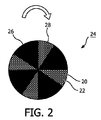
多孔性基板20は電極ユニット24の方に向けられている。この電極ユニット24は基板20に直接近接して設けられる。好ましくは、ディスク形状であり、少なくとも1つの回転可能な電極ウィング26及び電極ウィングの面内に空気ギャップ28を含む。しかし、最も好ましくは、電極24が、複数の回転可能な電極ウィング26及びそれらの間に設けられる複数の空気ギャップ28を含むことである。
The
好ましくは、少なくとも1つの電極ウィング26が少なくとも部分的に、白金、パラジウム、イリジウム又は金属酸化物、特にSrRuO3又はSrRhO3又はこれらの合金から形成される。これらの化合物は、特に、プラズマ形成で電極として作用するために好適である。加えて、これらの化合物は、プラズマで生成される高温度でもほとんどの酸素含有ガス中で安定である。
Preferably, at least one
少なくとも1つの電極ウィング26はそれにより、電極ウィング26の表面の導電性層を設けることで導電性となり得る。このことは、膜ユニット12の方に向けられる側で好ましく実現され得る。層は従って、上述の化合物の1つを含み得る。このことは、電極ウィング26が、好適な任意の材料から製造されることを可能にする。それにより導電性層は電極の特性を提供する。このことは、本発明による装置10と同様にかかる回転可能な電極ウィング26を、費用節約的に製造することを可能にする。又は、電極ウィング26は、前記材料で形成され得る。このことは特に電極ウィング26の製造を容易にする。
The at least one
回転可能な電極ウィング26表面と基板20との距離は、プラズマを点火して維持するための特に好ましい条件を持つようにポア22の直径よりも小さくするべきである。この理由で、加えて、回転可能な電極ウィング26表面と基板20との距離は、ポア22の長さ、例えば基板20の厚さよりも短くするべきである。加えて、ウィング26の導電性表面は、それぞれの空気ギャップ28の表面よりも大きくするべきである。
The distance between the surface of the
電極ユニット24の平面図が図2に示される。図2によれば、電極ユニット24は、非限定的に4つの電極ウィング26と、従ってそれらの間に設けられる4つの空気ギャップ28を持つ。空気ギャップ28の後ろ側、従って電極ユニット24の後ろ側には、多孔性基板20が、そこに設けられるポア22と共に見ることができる。電極ウィング26は回転可能であることから、膜ユニット12のある領域は、交互的に、ウィング26でカバーされるか、又は空気ギャップ28を通って開口される。
A plan view of the
電極ウィング26又は複数のウィング26はそれぞれ、少なくとも部分的に導電性であり、特に膜ユニット12の方に向けられている側でそうである。従って、電極ウィング26はプラズマ生成のための電極として作用する。詳細には、膜ユニット12の電極18と共に、回転可能な電極ウィング26は複数の小さいプラズマポンプを形成する。
Each
電極ユニット24は膜ユニット12の電極18と共に、その間にプラズマを生成し、これにより酸素含有ガスから酸素を分離するために酸素含有ガスを加熱し加圧する、という主目的を有する。図1を参照して、続いて酸素分離装置10は好ましい例示では次のように作用する。
The
酸素含有ガス、特に空気が電極ユニット24に案内される。酸素含有ガスを電極ユニット24へと移送するために、空気ブロワー30が電極ユニット24の上流に設けられる。空気ブロワー30は、電極ユニット24への酸素含有ガスの流れ又はその供給側への流れを増加させる。空気ブロワー30の下流で、加えて、加熱装置32、特に熱交換装置が設けられる。加熱装置32は、装置10の電力効率を、酸素含有ガス、例えば空気を予備加熱することで改善する。酸素含有ガスがその後電極ユニット24へ案内される。これは矢印34で模式的に示される。酸素分離ステップがその後実施され得る。酸素分離を達成するため、回転可能なウィング26が、膜ユニット12の前又は基板20の前で回転する。空気ギャップ28の領域で、新鮮な空気が電極ウィング26を通過し、又は電極ユニット24をそれぞれ通過し、膜ユニット12及びポア22内に案内されるが、これは矢印36で示される。この段階で、ガスは大気圧で存在し、即ち約1バールである。
電極ウィング26及び膜ユニット12の電極18が図示されていないが電源に接続されている場合には、プラズマは点火され、ウィング26と電極18との間で、従って、ポア20内で生成される。これは矢印38で模式的に示される。一般に、プラズマを生成するためにむしろ小さいエネルギーで十分である。詳細には、電力入力≧100Wから電力入力≦350Wの電力入力で十分であり、これは最終的に透過側の酸素流≧1リットル/分(1分あたり1リットル以上)、特に1分当たり数リットルの程度の酸素流となるように、温度及び膜の条件に依存する。この電力入力の範囲は在宅医療用に非常に好適なものでる。一般的に、しかし、生成されるプラズマにはいくつかのモードがある。特に、DCプラズマ、ACプラズマ、RFプラズマ、パルスプラズマなどが可能である。
An oxygen-containing gas, in particular air, is guided to the
If the
プラズマを与えることで温度が上昇する。ウィング26同様に空気ギャップ28が回転するということは、新鮮な空気で満たされるポア22が閉じ込められ、プラズマ生成の間ウィング26により、周囲に対して閉じかつ密閉されることである。膜ユニット12のポア22又は基板20内の酸素含有ガスは従って加熱され加圧される。例示的に、圧力は従って、プラズマにより生じる温度900Kまでガスの温度が増加することで1バールよりも高い値、特に3バールに増加され得る。加圧により、酸素含有ガスは膜14に対して押され、その結果酸素分離膜14を通過することで酸素が分離され、実質的に純粋な酸素の流れ16を形成することとなる。
The temperature rises by applying plasma. The rotation of the
電極ウィング26が回転するということは、ウィング26が続いて次の段階で空気ギャップ28に追いかけられるということである。なおもポア22内に存在する加圧及び、空気ギャップ28がそれぞれのポア22の前に位置するときにも短時間にわたってまだ生成しているプラズマにより、酸素が欠乏したガスがポア22から移動する。このことは矢印44で模式的に示される。プラズマが消失する際にはウィング26はもはやこの領域にはなく、ポア22内の低下圧力、特に圧力<<1バール(1バールよりずっと低い)で形成される欠乏性ガスは冷却され、その結果ポア22内に新たな空気が吹き込まれることとなる。従って、更なるサイクルが次のウィング26又はウィングが1つだけの場合には同じウィング26で開始される。電極ユニット24、又は回転電極ウィング26は、ポア22内の加圧空気を保持するとともにガス交換を実現することを担う弁として作用し得る。
That the
それぞれのポア22内でのプラズマ生成の開始及び終了は従って、電極ユニット24の回転又は少なくとも1つのウィング26の回転により定められる。しかし必要な場合、再点火パルスが加えられ得る。一般に、電界強度≧10kV/cm(10kV/cm以上)の電界強度がポア内でプラズマを(再)点火させるために使用されるべきである。この場合、ウィング26又は複数のウィング26の表面が構造化され得る。詳細には、導電性材料の領域は、回転方向に非導電性材料の領域によって続かれ得る。それぞれの領域のサイズにより、点火パルスは望ましい応用に向けて調節され得る。例えば、点火電圧は、前端(leading)領域又はストライプでそれぞれ生成され、一方プラズマ供給電圧は残る導電性表面で生成され得る。
Plasma generation of the start and termination of within each
上述のとおり、電極ユニット24はガスポンプとして作用する。電極ウィング26の回転により異なるサイクルで作用するけれど、好ましくは作用サイクルの高周波数によって、酸素含有ガスの直接かつ連続する流れを生成し得る。ウィング26の数及びそのサイズと共に、回転周波数が必要な応用に合せて調節され得る。これは約100Hz程度である。
As described above, the
スイングプロセスは必ずしも必要ではなく、というのは窒素は膜14には吸着されず、それにより酸素に対する透過性条件をなんら制限しないからである。
The swing process is not necessarily required because nitrogen is not adsorbed on the
生成された酸素流を集めるために、チューブ40が膜ユニット12又は膜14に接続される。もちろん好ましくは、チューブ40は気密密封され、全ての生成された酸素を望ましい応用に導くことを可能にするものである。ガスポンプがさらに、分離された酸素を望ましい応用に導くためにチューブ40内に設けられ得る。加えて、膜14の下流に冷却装置42が設けられ、酸素の分離された流れを冷却するために設けられ得る。冷却装置42は、例えばチューブ40内に設けられるか、又はチューブ40と流体連通するように構成され得る。従って、酸素は、装置10が特に好ましい方法でインサイチュプロセスで使用される場合には直接使用されることができ、又は酸素は好適な容器内に貯蔵され得る。生成された酸素の温度は、例えば医療用途、治療用などの望ましい用途で必要とされる温度に近く又は正確にその温度の範囲に調節され得る。冷却装置42は好ましくは、本発明による装置10の効率をさらに改善するために加熱装置32としての熱交換装置と接続される。
To collect the produced oxygen flow, the
全ての部品はもちろん周囲空気に対して密封され及び/又は適切な場合には対応するエネルギー源に接続され得る。加えて、適切な断熱材料が適切に設けられ得る。例えば、電極ユニット24は膜ユニット12と共に、効率改善のためにこれらの部品を熱絶縁するためのケース内に設けられ得る。
All parts can of course be sealed against ambient air and / or connected to a corresponding energy source where appropriate. In addition, a suitable thermal insulation material can be suitably provided. For example, the
図3から5を参照して、膜ユニットの異なる実施態様が記載される。 With reference to FIGS. 3 to 5, different embodiments of the membrane unit will be described.
図3では、膜ユニット12が模式的に示される。膜ユニット12はプラズマ点火及び維持のプロセスに寄与し、従って本発明の装置10のために本質的である。
In FIG. 3, the
図3による膜ユニット12は、1つの本質的部品として膜14を含む。上述の通り、酸素含有ガスから酸素を分離するためには、膜14は緻密である。従って、これは酸素選択的透過性である。
The
これらの性質を達成するためには、膜14は、無機酸化化合物から選択される固体セラミック膜であり得る。好ましくは膜14はペロブスカイト型又はフルオライト型結晶構造である。一例として、ペロブスカイト型は、Sr1−yBayCo1−xFexO3−z(これはドナー又はアクセプターでドープされていてもよく、ドープされていなくてもよく)、及びLa1−ySryFe1−xCrxO3−z(これは、ニオブ、マグネシウム、チタン又はガリウムでドープされていてもよく、されていなくてもよい)、
Sr1−y−xBayLaxCo1−b−cFebCrcO3−z(これは、例えば、ニオブ、マグネシウム、チタン又はガリウムなどのドナー又はアクセプターでドープされていてもよく、されていなくてもよい)、Ba1−xSrxTi03−z(これは、例えば、マンガン、鉄、クロム又は他のドープ化合物でドープされていてもよく、されていなくてもよい)、及びPbZr1−xTixO3−z(これは、例えば、鉄、ニオブ、ランタン、クロム又は他のドープ化合物などのドナー又はアクセプターでドープされていてもよく、されていなくてもよい)からなる群から選択される。好ましい例として、ペロブスカイト型材料は、Ba0.5Sr0.5Co0.5Fe0.2O3−δ(BSCF)が非常に好適である。又は、例えば、Sr0.5Ba0.5Co0.8Fe0.2O3−x薄膜が使用され得る。
In order to achieve these properties,
Sr 1-y-x Ba y La x Co 1-b-c Fe b Cr c O 3-z ( which is, for example, niobium, magnesium, may be doped with a donor or acceptor, such as titanium or gallium, Ba 1-x Sr x Ti0 3-z (which may or may not be doped with, for example, manganese, iron, chromium or other doped compounds), And PbZr 1-x Ti x O 3-z (which may or may not be doped with a donor or acceptor such as, for example, iron, niobium, lanthanum, chromium or other doped compounds) Selected from the group consisting of As a preferred example, Ba 0.5 Sr 0.5 Co 0.5 Fe 0.2 O 3-δ (BSCF) is very suitable as the perovskite type material. Or, for example, Sr 0.5 Ba 0.5 Co 0.8 Fe 0.2 O 3-x thin film may be used.
このタイプの無機膜14の一般的性質は、室温では全てのガスに対して完全に非透過性であるが、高温度に加熱されると酸素分子を通過させることが可能になる、ということである。主に、ほんの小さなサイズの膜の要求を満たし良好な酸素流を達成するためには700Kを超える温度が必要である。例えばBSCFと命名される材料は、例示的に説明すると、1275Kで毎分13ml/cm 2 の酸素流となり、この場合小さい膜厚で十分である。一般的に、膜14は、膜厚が0.1μmから50μmの範囲を持つことで十分であり得る。これは、装置10をコンパクトに形成し、さらに膜14を通じる高い酸素流を形成することを可能にする。加えて、薄膜を加熱するには必要な熱はより少なくなる。
The general property of this type of
膜14は多孔性基板20で支持される。基板20は、例えばシリコン、ガラス、石英又は酸化アルミニウムから形成され得る。しかし、任意の全ての基板20、金属基板などもまた使用され得る。基板は厚さが、厚さ≧50μm≦1mm(50μm以上で1mm以下)、特に厚さ≧100μm≦650μm(100μm以上で650μm以下)である。このことは、基板20を安定させ、また、例えばポータブル在宅医療用途で使用される本発明による装置10をコンパクトなものにすることを可能にする。基板20内にポア22が形成され得る。詳細には、基板20はピラー46を持ち、これは膜14と制御されて接触するガスを導入するためのポア22として定められる連続チャンネルが基板20内に設けられることが好ましい。これは、例えば基板20をエッチング又はサンドブラストすることで実現され得る。一般的には、マイクロ加工が適用され得る。ピラー46は好ましくは、幅が50μmから≦1mm(50μmから1mm以下)、特には≧200μmから≦800μm(200μm以上800μm以下)であり、これにより良好なガス流で十分高い安定性が可能となる。
The
基板20は好ましくは、5%から90%の間、特には20%から80%の間の多孔度を持つ。これは、膜ユニット12を通る非常に高いガス流を可能にする。加えて、基板20はなお、膜ユニット12が不安定となることを防止するための十分大きなサイズで、なお十分なピラー46を含む。多孔度がそれにより十分に定められるチャンネルにより主に形成され得る場合であっても、定められるチャンネル即ちピラー46に続く基板内に定められる多孔度を設けることを可能にする。これは、このような基板材料の多孔度により、又はピラー46の多孔度により形成され得る。
The
チャンネルは好適なプロセスで設けられるという事実により、それらは例えば膜14に、十分定められかつ十分定められ制御される空気流が接触することを可能にする。十分定められる又は定められるチャンネルはそれぞれ、従って、チャンネルの構造及びサイズが必要とされる要求により形状化されることを意味する。これらは従って、必要とされる要求により配置され適合化され得る。詳細には、それらは、幅≧30μmから≦5mm(30μm以上5mm以下)、特には幅≧100μmから≦800μm(100μm以上800μm以下)であり得る。しかし、チャンネル又はポア22それぞれが直径≧0.02mm(直径が0.02mm以上)であることが最も好ましい。
Due to the fact that the channels are provided in a suitable process, they allow, for example, the
本発明に従った装置10は、高いかつ十分定められるガス流束(flux)を可能にする効率的な酸素生成システムを形成し、及び薄膜14も扱うことができる安定したシステムを達成するために好適である。
The
上述のようにプラズマを生成させるために、膜ユニット12は電極18を含む。図1及び3を参照して、電極18は、基板20と膜14との間に設けられる薄層48として形成される。電極48は、少なくとも部分的に、白金、チタン、及びイリジウム、又は金属酸化物、特にイリジウム酸化物、SrRuO3又はSrRhO3又は上記化合物の合金から形成され得る。しかし、他の電極も可能である。
The
変形例として、基板20は膜14に直接に接続されることができ、一方で電極18を形成する層48は膜14の下流側、即ち基板20とは反対側に設けられ得る。
Alternatively, the
電極18を形成する層48の正確な位置からは独立して、電極18を形成する層48が、電極18と少なくとも1つの回転可能な電極ウィング26との間でプラズマを生成することが可能であることは重要であり、さらに、それが膜14を通じる酸素の流れを妨げないことが重要である。従って、層48が基板20と膜14との間に設けられる場合には、ピラー46の領域にのみ位置されるか、又はピラー46と膜14との間に設けられ、それによりポア22に接触する。従って、膜14を通る酸素流れを邪魔することはない。全体表面に亘り膜14の隣に設けられる場合、層48は好ましくは多孔性であり、これにより層48を通る酸素の流れを邪魔しない。1つの変形実施例では、層48はガス流を可能にする孔を持つ。従って、これは例えば篩いとして設計され得る。
Independent of the precise location of the
膜14の透過側での層48の配置についても同様である。層48は全体表面上に位置されることが主に好ましい。この場合、これは全体に、例えば篩い形状で設けられるか、又は多孔性であり、酸素に対して透過性であり得る。
The same applies to the arrangement of the
膜ユニット12のさらなる実施態様が図4に示される。図4を参照して、膜ユニット12はさらに、カバー層50、50’を基板20の一方側又は両方側に含む。この点で、カバー層50、50’は好ましくはシリコン窒化物又はガラスからなる。これは特に、膜14に含まれる成分と基板20に含まれる成分との反応を防止することを可能にする。詳細には、膜14の好適な成分としてのバリウムと、基板20の好適な成分としてのシリコンとの反応が防止される。加えて、膜14とは反対側の基板20の面に設けられる場合には、カバー層50’は、ポア22又はチャンネルそれぞれを望ましく形成又は形状化することをそれぞれ助け、それにより例えばマスクとして作用することができる。特に、カバー層50、50’は、任意の堆積技術、例えば熱酸化により与えられ得る。シリコン窒化物層は、任意の堆積技術、例えば化学気相堆積により与えられ得る。ガラス層は、例えばスピンオンガラス層であり得る。カバー層50、50’の厚さは、好ましくは、100nmと100μmの間、特に100nmと10μmとの間である。
A further embodiment of the
また図4に示されるように、電極18を形成する層48が膜14の下流側に設けられ得る。しかし、電極層48は、同様に膜14の上流側に設けることも可能である。この場合には、カバー層50と膜14との間、又はカバー層50と基板20との間に設けられ得る。さらなる実施態様では、チタン酸化物などのバリア層が、カバー層50と電極18との間に適用され得る。
Also, as shown in FIG. 4, a
層48に関して上述のように、層48及び層50は酸素の流れを妨げるべきではない。従って、全表面に即ちポア22内に設けられる場合、それは多孔性であるか又は孔を含み、これにより膜14を通る適切な酸素の流れを可能にするべきである。
As described above with respect to
膜ユニット12のさらなる実施態様が図5に示される。図5による実施態様は、図4による実施態様と類似する。しかし、図5によれば、膜ユニット12はさらに、バリア層52を膜14とカバー層50との間に含む。このバリア層52は好ましくは、シリコン酸化物、チタン酸化物、マグネシウム酸化物、ジルコニウム酸化物、チタン酸ジルコン酸塩、アルミニウム酸化物及びタンタル酸化物又はこれらの組み合わせを含む群から選択される材料を含む。バリア層52は、任意の堆積方法で適用され、例えば酸化物のスパッタリング、金属のスパッタリングに続く熱酸化、又はスピンオン又は化学気相堆積などである。これはまた、膜14及びカバー50の材料がそれぞれお互いにある程度相互作用し得る材料から形成される場合に、カバー層50と膜14との間の中間層として作用し得るものである。また、電極層48は、膜14の上流側及び下流側の両側に設けられ得る。層48に関して上述したように、層48及びバリア層52は酸素の流れを妨げるべきではない。従って、全表面上に、即ちポア22内に設けられる場合には、これは多孔性であるか、又は孔が設けられ、膜14を通る酸素の好適な流れを可能にする。
A further embodiment of the
加えて、全ての実施態様において、さらなる保護層が膜14上又は電極層48上にそれぞれ設けられ得る。この保護層は、例えば、膜14を機械的に保護し、及び従って、本発明に従った膜14の耐久性を改善することができる。保護層は好ましくは、無機又は有機層から形成される。また、これは好ましくは孔を持つか、多孔性として形成され、これにより膜14を通る酸素の好適な流れを可能にする。
In addition, in all embodiments, additional protective layers may be provided on the
さらに、それぞれの層、即ち電極層48、カバー層50、50’及び/又はバリア層52は、ピラー20内又はポア22内に、又はチャンネル内にそれぞれ設けられ、又はお互いに独立して両方に設けられ得る。ポア22内に設けられる場合は、酸素流れを妨げるべきではない。
Furthermore, the respective layers, i.e. the
留意すべきことは、図3から5を参照して説明された全ての実施態様は、本発明に従った装置10で使用され得る、ということである。
It should be noted that all the embodiments described with reference to FIGS. 3 to 5 can be used with the
本発明は、図面及び上記記載に基づき詳細に説明されたけれど、かかる図示及び記載は、図示又は例示するものであり、本発明を何ら制限するものではなく、本発明は開示された実施態様に限定されるべきではない、ということである。開示された実施態様の他の変形例は、図面、開示内容及び特許請求の範囲に基づき当業者により理解され実施され得るものである。特許請求の範囲において、用語「含む」は他の要素やステップを除外するものではなく、「ひとつの」は複数を除外するものではない。ある手段が相互に異なる従属請求項に記載されているという単なる事実は、これらの手段の組み合わせが有利に使用されない、ということを意味するものではない。請求項のカッコ内の参照番号は特許請求の範囲を限定するように解釈されるべきではない。 Although the present invention has been described in detail with reference to the drawings and the above description, such illustration and description are intended to illustrate or exemplify the present invention and do not limit the present invention in any way. It should not be limited. Other variations of the disclosed embodiments can be understood and implemented by those skilled in the art based on the drawings, the disclosure, and the claims. In the claims, the term “comprising” does not exclude other elements or steps, and “a” does not exclude a plurality. The mere fact that certain measures are recited in mutually different dependent claims does not indicate that a combination of these measured cannot be used to advantage. Reference numerals in parentheses in the claims should not be construed as limiting the scope of the claims.
Claims (13)
膜ユニットと、電極ユニットとを含み、
前記膜ユニットは、多孔性基板、緻密な膜及び少なくとも1つの電極を含み、
前記電極ユニットは、少なくとも部分的に導電性である少なくとも1つの回転可能な電極ウィングを有し、さらに、酸素含有ガスが当該電極ユニットを通過することを可能にする少なくとも1つの空気ギャップを有し、
前記電極ユニットは、酸素含有ガスを当該電極ユニットに案内する供給側を有し、該供給側は、前記膜ユニットとは反対側にあり、
前記多孔性基板が前記電極ユニットの方に向けられ、
前記電極ユニット及び前記電極は、前記少なくとも1つの回転可能な電極ウィングと前記電極との間で前記多孔性基板のポア内にプラズマを形成するように配置されている、
装置。 A device that separates oxygen from oxygen-containing gas:
Including a membrane unit and an electrode unit;
The membrane unit includes a porous substrate, a dense membrane and at least one electrode,
The electrode unit may have a single rotatable electrode wing even without least Ru least partially conductive der further comprises at least one air gap oxygen-containing gas to permit passage of the electrode unit Have
The electrode unit has a supply side that guides the oxygen-containing gas to the electrode unit, and the supply side is on the side opposite to the membrane unit;
The porous substrate is directed toward the electrode unit;
The electrode unit and the electrode are arranged to form a plasma in the pores of the porous substrate between the at least one rotatable electrode wing and the electrode,
apparatus.
請求項1に記載の装置を準備し、前記電極ユニットが酸素含有ガスと流体連通し、
前記少なくとも1つの回転可能な電極ウィングを回転させ、及び
前記電極及び前記少なくとも1つの回転可能な電極ウィングに電圧を供給し、前記多孔性基板のポア内にプラズマを生成させる、ことを含む方法。 A method of separating oxygen from an oxygen-containing gas, the said method:
Providing an apparatus according to claim 1, wherein the electrode unit is in fluid communication with an oxygen-containing gas;
Wherein rotating the at least one rotatable electrode wing, and supplies the electrodes and a voltage to the at least one rotatable electrode wing, said porous to generate plasma within the pores of the substrate, the method comprising.
Applications Claiming Priority (3)
| Application Number | Priority Date | Filing Date | Title |
|---|---|---|---|
| EP10188478 | 2010-10-22 | ||
| EP10188478.1 | 2010-10-22 | ||
| PCT/IB2011/054622 WO2012052915A1 (en) | 2010-10-22 | 2011-10-18 | Arrangement and method for separating oxygen |
Publications (3)
| Publication Number | Publication Date |
|---|---|
| JP2014500136A JP2014500136A (en) | 2014-01-09 |
| JP2014500136A5 JP2014500136A5 (en) | 2015-09-10 |
| JP5906247B2 true JP5906247B2 (en) | 2016-04-20 |
Family
ID=43921115
Family Applications (1)
| Application Number | Title | Priority Date | Filing Date |
|---|---|---|---|
| JP2013534432A Expired - Fee Related JP5906247B2 (en) | 2010-10-22 | 2011-10-18 | Oxygen separator and method |
Country Status (7)
| Country | Link |
|---|---|
| US (1) | US8906137B2 (en) |
| EP (1) | EP2629880B1 (en) |
| JP (1) | JP5906247B2 (en) |
| CN (1) | CN103180027B (en) |
| BR (1) | BR112013009352B1 (en) |
| RU (1) | RU2571132C2 (en) |
| WO (1) | WO2012052915A1 (en) |
Families Citing this family (10)
| Publication number | Priority date | Publication date | Assignee | Title |
|---|---|---|---|---|
| CN102753251B (en) * | 2009-12-17 | 2016-11-16 | 皇家飞利浦电子股份有限公司 | Utilize plasma-pump and the oxygen separation method of film and system |
| CN102791355B (en) * | 2010-03-05 | 2015-04-01 | 皇家飞利浦电子股份有限公司 | Oxygen separation membrane |
| WO2012147015A1 (en) | 2011-04-28 | 2012-11-01 | Koninklijke Philips Electronics N.V. | Method and arrangement for generating oxygen |
| US9592469B2 (en) * | 2012-07-25 | 2017-03-14 | Koninklijke Philips N.V. | Oxygen separation device for a pressure swing adsorption system |
| WO2014038194A1 (en) * | 2012-09-04 | 2014-03-13 | アトナープ株式会社 | Membrane exchange unit and systems having membrane exchange units |
| JP6689188B2 (en) * | 2013-03-15 | 2020-04-28 | ザ ジェネラル ホスピタル コーポレイション | Inspiratory synthesis of nitric oxide |
| WO2015064194A1 (en) * | 2013-10-30 | 2015-05-07 | 東京エレクトロン株式会社 | Deposition device and deposition method |
| WO2015109236A1 (en) * | 2014-01-16 | 2015-07-23 | Ahmad Samir S | Oxygen concentrator for high pressure oxygen delivery with oxygen circulation loop and improved portability |
| CN108815998B (en) * | 2018-05-31 | 2021-02-19 | 武汉大学 | Separation method of electronegative gas electromigration membrane |
| CN114904376A (en) * | 2022-06-06 | 2022-08-16 | 北京航空航天大学 | Carbon dioxide conversion oxygen-making device |
Family Cites Families (20)
| Publication number | Priority date | Publication date | Assignee | Title |
|---|---|---|---|---|
| EP0453441B1 (en) * | 1989-01-13 | 1995-05-31 | Minntech Corporation | Oxygenator wedge configuration |
| US5296110A (en) * | 1991-01-07 | 1994-03-22 | University Of Central Florida | Apparatus and method for separating oxygen from air |
| JPH0573849U (en) * | 1992-03-06 | 1993-10-08 | 日新電機株式会社 | Ion source |
| DE69619299T2 (en) * | 1995-06-07 | 2002-10-10 | Air Prod & Chem | Oxygen production with ion transport membranes and energy recovery |
| US5865878A (en) * | 1997-04-29 | 1999-02-02 | Praxair Technology, Inc. | Method for producing oxidized product and generating power using a solid electrolyte membrane integrated with a gas turbine |
| US6149714A (en) * | 1997-06-05 | 2000-11-21 | Praxair Technology, Inc. | Process for enriched combustion using solid electrolyte ionic conductor systems |
| US5888272A (en) * | 1997-06-05 | 1999-03-30 | Praxair Technology, Inc. | Process for enriched combustion using solid electrolyte ionic conductor systems |
| US6368383B1 (en) * | 1999-06-08 | 2002-04-09 | Praxair Technology, Inc. | Method of separating oxygen with the use of composite ceramic membranes |
| US7646544B2 (en) * | 2005-05-14 | 2010-01-12 | Batchko Robert G | Fluidic optical devices |
| US20020100836A1 (en) * | 2001-01-31 | 2002-08-01 | Hunt Robert Daniel | Hydrogen and oxygen battery, or hudrogen and oxygen to fire a combustion engine and/or for commerce. |
| GB2397303B (en) * | 2003-01-17 | 2007-04-04 | Smartmembrane Corp | Gas separation membranes |
| GB2397821B (en) * | 2003-01-30 | 2006-04-05 | Smartmembrane Corp | Oxygen and nitrogen enriched atmospheres in aircraft |
| JP2004323334A (en) * | 2003-04-28 | 2004-11-18 | Jfe Steel Kk | Oxygen manufacturing apparatus, manufacturing method of the same, and oxygen manufacture method |
| JP2007527468A (en) * | 2003-07-10 | 2007-09-27 | プラクスエア・テクノロジー・インコーポレイテッド | Oxygen ion transport complex element |
| JP2005270849A (en) | 2004-03-25 | 2005-10-06 | Canon Inc | Plasma processing apparatus and its method |
| JP4466422B2 (en) | 2004-06-29 | 2010-05-26 | 三菱電機株式会社 | Volatile organic compound processing equipment |
| JP2006161108A (en) * | 2004-12-08 | 2006-06-22 | Matsushita Electric Ind Co Ltd | Oxygen pump element and oxygen feeding device using the same |
| JP4855013B2 (en) * | 2005-08-18 | 2012-01-18 | 株式会社ノリタケカンパニーリミテド | Oxygen separation membrane and hydrocarbon oxidation reactor |
| DE102007056423A1 (en) * | 2007-11-23 | 2009-06-04 | Süd-Chemie AG | Production and use of new polyanilines for water treatment |
| WO2012147015A1 (en) * | 2011-04-28 | 2012-11-01 | Koninklijke Philips Electronics N.V. | Method and arrangement for generating oxygen |
-
2011
- 2011-10-18 US US13/879,066 patent/US8906137B2/en active Active
- 2011-10-18 CN CN201180050835.2A patent/CN103180027B/en active Active
- 2011-10-18 RU RU2013123135/05A patent/RU2571132C2/en active
- 2011-10-18 EP EP11778716.8A patent/EP2629880B1/en active Active
- 2011-10-18 JP JP2013534432A patent/JP5906247B2/en not_active Expired - Fee Related
- 2011-10-18 WO PCT/IB2011/054622 patent/WO2012052915A1/en active Application Filing
- 2011-10-18 BR BR112013009352-8A patent/BR112013009352B1/en not_active IP Right Cessation
Also Published As
| Publication number | Publication date |
|---|---|
| EP2629880B1 (en) | 2017-04-05 |
| JP2014500136A (en) | 2014-01-09 |
| WO2012052915A1 (en) | 2012-04-26 |
| CN103180027A (en) | 2013-06-26 |
| US20130213227A1 (en) | 2013-08-22 |
| CN103180027B (en) | 2015-11-25 |
| BR112013009352A2 (en) | 2016-07-26 |
| RU2013123135A (en) | 2014-11-27 |
| US8906137B2 (en) | 2014-12-09 |
| BR112013009352B1 (en) | 2020-07-28 |
| RU2571132C2 (en) | 2015-12-20 |
| EP2629880A1 (en) | 2013-08-28 |
Similar Documents
| Publication | Publication Date | Title |
|---|---|---|
| JP5906247B2 (en) | Oxygen separator and method | |
| JP2014500136A5 (en) | ||
| JP6096513B2 (en) | Plasma pump and membrane oxygen separation method and system | |
| JP2013514123A5 (en) | ||
| JP5848780B2 (en) | Method and configuration for generating oxygen | |
| CN102781825A (en) | Method for generating nitric oxide | |
| TWI229615B (en) | Method for carbon monoxide reduction during thermal/wet abatement of organic compounds | |
| US20170101314A1 (en) | Method and arrangement for generating oxygen | |
| JP5847181B2 (en) | Method and apparatus for generating gas | |
| JP2013543430A5 (en) | ||
| JP2014522361A5 (en) | ||
| US20230039518A1 (en) | Methods and apparatus for generating atmospheric pressure, low temperature plasma | |
| KR20110068150A (en) | Oxygen supply apparatus including oxygen separation membrane | |
| JP2003000714A (en) | Air supply device for breathing |
Legal Events
| Date | Code | Title | Description |
|---|---|---|---|
| A621 | Written request for application examination |
Free format text: JAPANESE INTERMEDIATE CODE: A621 Effective date: 20141016 |
|
| A521 | Request for written amendment filed |
Free format text: JAPANESE INTERMEDIATE CODE: A523 Effective date: 20150717 |
|
| A977 | Report on retrieval |
Free format text: JAPANESE INTERMEDIATE CODE: A971007 Effective date: 20150827 |
|
| A131 | Notification of reasons for refusal |
Free format text: JAPANESE INTERMEDIATE CODE: A131 Effective date: 20150915 |
|
| A521 | Request for written amendment filed |
Free format text: JAPANESE INTERMEDIATE CODE: A523 Effective date: 20151127 |
|
| TRDD | Decision of grant or rejection written | ||
| A01 | Written decision to grant a patent or to grant a registration (utility model) |
Free format text: JAPANESE INTERMEDIATE CODE: A01 Effective date: 20160223 |
|
| A61 | First payment of annual fees (during grant procedure) |
Free format text: JAPANESE INTERMEDIATE CODE: A61 Effective date: 20160318 |
|
| R150 | Certificate of patent or registration of utility model |
Ref document number: 5906247 Country of ref document: JP Free format text: JAPANESE INTERMEDIATE CODE: R150 |
|
| R250 | Receipt of annual fees |
Free format text: JAPANESE INTERMEDIATE CODE: R250 |
|
| R250 | Receipt of annual fees |
Free format text: JAPANESE INTERMEDIATE CODE: R250 |
|
| R250 | Receipt of annual fees |
Free format text: JAPANESE INTERMEDIATE CODE: R250 |
|
| R250 | Receipt of annual fees |
Free format text: JAPANESE INTERMEDIATE CODE: R250 |
|
| LAPS | Cancellation because of no payment of annual fees |