JP5902457B2 - Golf club head - Google Patents
Golf club head Download PDFInfo
- Publication number
- JP5902457B2 JP5902457B2 JP2011268329A JP2011268329A JP5902457B2 JP 5902457 B2 JP5902457 B2 JP 5902457B2 JP 2011268329 A JP2011268329 A JP 2011268329A JP 2011268329 A JP2011268329 A JP 2011268329A JP 5902457 B2 JP5902457 B2 JP 5902457B2
- Authority
- JP
- Japan
- Prior art keywords
- face
- golf club
- club head
- forming
- forming portion
- Prior art date
- Legal status (The legal status is an assumption and is not a legal conclusion. Google has not performed a legal analysis and makes no representation as to the accuracy of the status listed.)
- Active
Links
- 230000037431 insertion Effects 0.000 claims description 17
- 238000003780 insertion Methods 0.000 claims description 17
- 239000000463 material Substances 0.000 claims description 13
- XEEYBQQBJWHFJM-UHFFFAOYSA-N Iron Chemical compound [Fe] XEEYBQQBJWHFJM-UHFFFAOYSA-N 0.000 claims description 9
- 238000013016 damping Methods 0.000 claims description 9
- 230000002093 peripheral effect Effects 0.000 claims description 7
- 229910052742 iron Inorganic materials 0.000 claims description 5
- 239000002184 metal Substances 0.000 claims description 4
- 229910052751 metal Inorganic materials 0.000 claims description 4
- 239000000025 natural resin Substances 0.000 claims description 2
- 229920003002 synthetic resin Polymers 0.000 claims description 2
- 239000000057 synthetic resin Substances 0.000 claims description 2
- 230000005484 gravity Effects 0.000 description 8
- 229910045601 alloy Inorganic materials 0.000 description 7
- 239000000956 alloy Substances 0.000 description 7
- 239000007769 metal material Substances 0.000 description 4
- 238000005452 bending Methods 0.000 description 3
- 235000009508 confectionery Nutrition 0.000 description 3
- 239000011347 resin Substances 0.000 description 3
- 229920005989 resin Polymers 0.000 description 3
- 229920000459 Nitrile rubber Polymers 0.000 description 2
- 238000005266 casting Methods 0.000 description 2
- 230000002542 deteriorative effect Effects 0.000 description 2
- 229910000851 Alloy steel Inorganic materials 0.000 description 1
- OKTJSMMVPCPJKN-UHFFFAOYSA-N Carbon Chemical compound [C] OKTJSMMVPCPJKN-UHFFFAOYSA-N 0.000 description 1
- 229910001018 Cast iron Inorganic materials 0.000 description 1
- 229910000881 Cu alloy Inorganic materials 0.000 description 1
- 244000043261 Hevea brasiliensis Species 0.000 description 1
- 229910001240 Maraging steel Inorganic materials 0.000 description 1
- 229910000861 Mg alloy Inorganic materials 0.000 description 1
- 229910001069 Ti alloy Inorganic materials 0.000 description 1
- 239000006096 absorbing agent Substances 0.000 description 1
- 239000000853 adhesive Substances 0.000 description 1
- 230000001070 adhesive effect Effects 0.000 description 1
- 230000002238 attenuated effect Effects 0.000 description 1
- 238000005242 forging Methods 0.000 description 1
- 229910002804 graphite Inorganic materials 0.000 description 1
- 239000010439 graphite Substances 0.000 description 1
- KHYBPSFKEHXSLX-UHFFFAOYSA-N iminotitanium Chemical compound [Ti]=N KHYBPSFKEHXSLX-UHFFFAOYSA-N 0.000 description 1
- 150000002505 iron Chemical class 0.000 description 1
- 229920003052 natural elastomer Polymers 0.000 description 1
- 229920001194 natural rubber Polymers 0.000 description 1
- 229910001000 nickel titanium Inorganic materials 0.000 description 1
- 239000000843 powder Substances 0.000 description 1
- 238000009497 press forging Methods 0.000 description 1
- 230000035939 shock Effects 0.000 description 1
- 229910001220 stainless steel Inorganic materials 0.000 description 1
- 239000010935 stainless steel Substances 0.000 description 1
- 230000001629 suppression Effects 0.000 description 1
- 238000003466 welding Methods 0.000 description 1
Images


Classifications
-
- A—HUMAN NECESSITIES
- A63—SPORTS; GAMES; AMUSEMENTS
- A63B—APPARATUS FOR PHYSICAL TRAINING, GYMNASTICS, SWIMMING, CLIMBING, OR FENCING; BALL GAMES; TRAINING EQUIPMENT
- A63B60/00—Details or accessories of golf clubs, bats, rackets or the like
- A63B60/02—Ballast means for adjusting the centre of mass
-
- A—HUMAN NECESSITIES
- A63—SPORTS; GAMES; AMUSEMENTS
- A63B—APPARATUS FOR PHYSICAL TRAINING, GYMNASTICS, SWIMMING, CLIMBING, OR FENCING; BALL GAMES; TRAINING EQUIPMENT
- A63B53/00—Golf clubs
- A63B53/04—Heads
- A63B53/0433—Heads with special sole configurations
-
- A—HUMAN NECESSITIES
- A63—SPORTS; GAMES; AMUSEMENTS
- A63B—APPARATUS FOR PHYSICAL TRAINING, GYMNASTICS, SWIMMING, CLIMBING, OR FENCING; BALL GAMES; TRAINING EQUIPMENT
- A63B53/00—Golf clubs
- A63B53/04—Heads
- A63B53/047—Heads iron-type
-
- A—HUMAN NECESSITIES
- A63—SPORTS; GAMES; AMUSEMENTS
- A63B—APPARATUS FOR PHYSICAL TRAINING, GYMNASTICS, SWIMMING, CLIMBING, OR FENCING; BALL GAMES; TRAINING EQUIPMENT
- A63B53/00—Golf clubs
- A63B53/04—Heads
- A63B2053/0491—Heads with added weights, e.g. changeable, replaceable
-
- A—HUMAN NECESSITIES
- A63—SPORTS; GAMES; AMUSEMENTS
- A63B—APPARATUS FOR PHYSICAL TRAINING, GYMNASTICS, SWIMMING, CLIMBING, OR FENCING; BALL GAMES; TRAINING EQUIPMENT
- A63B53/00—Golf clubs
- A63B53/04—Heads
- A63B53/0416—Heads having an impact surface provided by a face insert
- A63B53/042—Heads having an impact surface provided by a face insert the face insert consisting of a material different from that of the head
-
- A—HUMAN NECESSITIES
- A63—SPORTS; GAMES; AMUSEMENTS
- A63B—APPARATUS FOR PHYSICAL TRAINING, GYMNASTICS, SWIMMING, CLIMBING, OR FENCING; BALL GAMES; TRAINING EQUIPMENT
- A63B60/00—Details or accessories of golf clubs, bats, rackets or the like
- A63B60/54—Details or accessories of golf clubs, bats, rackets or the like with means for damping vibrations
Description
本発明は、アイアン型のゴルフクラブヘッドに関する。 The present invention relates to an iron type golf club head.
アイアン型のゴルフクラブヘッドの構造として、フェース部材とヘッド本体とを固着したゴルフクラブヘッドが知られている(特許文献1及び2)。特許文献1にはフェース部材とヘッド本体との間に衝撃吸収体を設けたものが開示されている。また、特許文献2には、フェース部材の下端部を後方に折り曲げて、フェース部の下部を撓み易くしたものが開示されている。
As a structure of an iron type golf club head, a golf club head in which a face member and a head main body are fixed is known (
フェース部の下部を撓み易くした場合、スイートスポットから外れてフェース部の下部でゴルフボールを打撃した場合に、飛距離の低下を抑制できる。しかし、撓みが大きくなると打感が悪くなる。 When the lower part of the face part is easily bent, it is possible to suppress a decrease in the flight distance when the golf ball is hit from the lower part of the face part outside the sweet spot. However, the feeling of hitting becomes worse as the flexure increases.
本発明の目的は、フェース部の下部を撓み易くしながら、打感を向上することにある。 An object of the present invention is to improve the hit feeling while easily bending the lower portion of the face portion.
本発明によれば、フェース部と、ソール部とを備えたアイアン型のゴルフクラブヘッドにおいて、ヘッド本体と、前記ヘッド本体に固着されるフェース部材と、を備え、前記フェース部材は、前記フェース部を形成するフェース形成部と、前記フェース形成部からバック側へ延設され、前記ソール部の前部を形成する前部形成部と、を含み、前記ヘッド本体は、前記フェース部材の背面を露出させる開口部を画定する周縁部を含み、前記周縁部は、前記ソール部を形成するソール形成部を含み、前記ソール形成部は、前記前部形成部よりも厚肉であり、前記ソール形成部の前記フェース部側の端面が、前記前部形成部のバック側端面が固着される下部領域と、前記下部領域よりも上方の上部領域と、を含み、前記上部領域と、前記フェース部材の背面との間の隙間に弾性体が配設され、
前記上部領域が凹部を含み、前記凹部に、前記ヘッド本体と材料が異なる挿入部材を挿入したゴルフクラブヘッドが提供される。
According to the present invention, an iron-type golf club head including a face portion and a sole portion includes a head main body and a face member fixed to the head main body, and the face member includes the face portion. A head forming portion that extends from the face forming portion to the back side and that forms the front portion of the sole portion, and the head body exposes the back surface of the face member. A peripheral portion defining an opening to be formed, wherein the peripheral portion includes a sole forming portion that forms the sole portion, and the sole forming portion is thicker than the front portion forming portion, The end surface of the face portion side includes a lower region to which the back side end surface of the front portion forming portion is fixed, and an upper region above the lower region, the upper region, and the face portion Elastic body is disposed in a gap between the back of,
A golf club head is provided in which the upper region includes a recess, and an insertion member made of a material different from that of the head body is inserted into the recess .
本発明によれば、フェース部の下部を撓み易くしながら、打感を向上することができる。 According to the present invention, it is possible to improve the hit feeling while easily bending the lower portion of the face portion.
図1は本発明の第1実施形態に係るアイアン型のゴルフクラブヘッド1の外観図であり、フェース部側から見た斜視図である。本発明は、アイアン型のゴルフクラブヘッド全般に好適である。
FIG. 1 is an external view of an iron type
ゴルフクラブヘッド1は、フェース部(打撃面)2と、ソール部3と、ホゼル部4と、を備える。ホゼル部4には不図示のシャフトが装着される。フェース部2には複数本のスコアライン2aが形成されている。各々のスコアライン2aはトウ−ヒール方向に延設された、互いに平行な直線状の溝である。
The
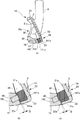
ゴルフクラブヘッド1は、ヘッド本体10と、ヘッド本体10に固着されるフェース部材20と、を備える。図2(A)は図1の線I−Iに沿う断面図、図3はゴルフクラブヘッド1の分解斜視図、図4はヘッド本体10の外観図であり、フェース部2側から見た図である。
The
フェース部材20は、フェース形成部21と、フェース形成部21の下端部からバック側へ延設された前部形成部22と、を含む。フェース形成部21はその正面がフェース部2を形成する。前部形成部22はソール部3の前部3a(フェース部2側の部分)を形成する。
The
フェース部材20は、金属材料、例えば、チタン合金、ステンレス、マレージング鋼、鋼合金等で形成される。フェース部材20は、例えば、鋳造や鍛造や、板材をプレスして成型するプレス鍛造等により形成することができる。鋳造は、複雑な形状が作り易いという利点がある。
The
ヘッド本体10はホゼル部4を備える。また、ヘッド本体10はフェース部材20の背面(フェース形成部21の背面21a)をバック側に露出させる開口部10aを含む。開口部10aは、周縁部11によって画定されている。
The
周縁部11は、上部形成部12、トウ側のサイド形成部13、ソール形成部14及びヒール側のサイド形成部15を含む。サイド形成部13は、ゴルフクラブヘッド1のトウ側のサイド部を形成する部分であり、フェース部2側の端面131を含む。端面131は、ソール部3側において、外側領域131aと、内側領域131bとに分かれている。内側領域131bは外側領域131aよりもバック側に凹んでいる。
The
ソール形成部14は、前部3aを除いてソール部3を形成する部分であり、フェース部2側の端面141を含む。端面141は、仮想的に下部領域141aと、下部領域141aよりも上方の上部領域141bとに2分される。上部領域141bと内側領域131bとは互いに連続して形成されている。上部領域141bには凹部142が形成されている。凹部142はヒール側からトウ側に延設され、トウ側においてはやや上方へ曲折して内側領域131bまで延びている。
The
ソール形成部14には、また、重心位置調整用の錘部材16が固着されている。錘部材16はソール形成部14に設けた凹部に固着されている。錘部材16は、例えば、ヘッド本体10とは異なる金属材料から形成される。
Further, a
フェース部材20は、そのフェース形成部21の背面21aが上部形成部12のフェース部2側の端面及び外側領域131aに固着され、その前部形成部22のバック側の端面22aが下側領域141aに固着される。ヘッド本体10とフェース部材20との固着は、例えば、溶接により行う。内側領域131b、上部領域141bはフェース形成部21の背面21aから離間する。
図2(A)に示すようにソール形成部14は、前部形成部22よりも厚肉となっている。ソール形成部14を相対的に厚肉とすることで、ゴルフクラブヘッドの剛性向上や低重心化を図れる。また、前部形成部22を含むフェース部材2全体を相対的に薄肉とすることで、打撃時にフェース形成部21を撓み易くすることができる。
As shown in FIG. 2A, the
本実施形態の場合、前部形成部22を設けたことで、ソール形成部14の端面141と、フェース形成部21との間に隙間を形成している。これによって、フェース形成部21の下部を撓み易くしている。この結果、フェース部2の下部でゴルフボールを打撃した場合に、飛距離の低下を抑制できる。
In the present embodiment, by providing the front
ソール形成部14の端面141と、フェース形成部21との間の隙間、より具体的には、上部領域141bと、フェース形成部21の背面21aとの間の隙間に弾性体30が充填され、上部領域141b及び背面21aに密着している。弾性体30は例えば接着剤によって、この隙間に固定される。
The
弾性体30は、例えば、合成樹脂材料や天然樹脂材料(例えば天然ゴム)からなる。弾性体30は、粘弾性体が好ましく、例えば、NBR(アクリロニトリルブタジエンゴム)である。また、弾性体30を、このような樹脂材料に金属粉を混入することで形成し、重心位置の調整を行うようにしてもよい。本実施形態の場合、上記の通り、フェース形成部21の下部を撓み易くしているが、撓みが大きくなると打感が悪くなる場合がある。しかし、この弾性体30により振動が減衰され易くなる。こうして本実施形態では、フェース部2の下部を撓み易くしながら、打感を向上することができる。
The
本実施形態の場合、弾性体30はL字型をなしており、内側領域131bとフェース形成部21の背面21aとの隙間にも延在している。このため、フェース部2のスイートスポットから外れて、トウ側でゴルフボールを打撃した場合にも打感が悪くなることを防止できる。
In the case of the present embodiment, the
凹部142には、ヘッド本体10と材料が異なる挿入部材40が挿入されている。挿入部材40の材料は、目的に応じて適宜選択できる。重心位置の調整を目的とする場合は、ヘッド本体10と比重が異なる材料とすることができ、特に、低重心化を目的とする場合はヘッド本体10よりも比重が重い、金属材料とすることができる。
An
打感の向上を目的とする場合は、ヘッド本体10よりも制振性能が高い金属材料とすることができる。挿入部材40をヘッド本体10よりも制振性能が高い金属製とすることで、弾性体30と挿入部材40とにより打感の向上を図れる。
For the purpose of improving the hit feeling, a metal material having higher vibration damping performance than the
この場合、挿入部材40は制振合金とすることが好ましい。制振合金としては、例えば、片状黒鉛鋳鉄、マグネシウム合金、サイレンタロイ(Fe-Cr-Al)、Ni−Ti合金、Mn−Cu合金が挙げられる。挿入部材40を制振合金とし、弾性体30を樹脂材料とした場合、制振合金により相対的に高周波数の振動が、また、樹脂材料により相対的に低周波数の振動が、それぞれ抑制され、振動抑制領域を広範囲にすることができる。また、挿入部材40を制振合金とすることで、ソール部3の剛性を確保することができ、また、ゴルフクラブヘッド1の低重心化も図れる。
In this case, the
本実施形態の場合、上記の通り、凹部142はトウ側においてはやや上方へ曲折して内側領域131bまで延びている。そして、挿入部材40もトウ側においてはやや上方へ曲折して内側領域131bまで延びている。したがって、挿入部材40を制振合金とした場合、フェース部2のスイートスポットから外れて、トウ側でゴルフボールを打撃した場合に打感が悪くなることを更に防止できる。
In the case of the present embodiment, as described above, the
なお、図2(B)及び(C)に示すように、挿入部材40のフェース部側の端面40aと、上部領域141bの表面とには、段差Dがあることが好ましい。つまり、凹部142の深さと、挿入部材40の厚さとに差を設けることが好ましい。このようにすると、挿入部材40が上部領域141bから突出するか(図2(B))、凹むことになる(図2(C))。図2(B)の構成の場合は、挿入部材40の先端が弾性体30に食い込み、図2(C)の構成の場合は、弾性体30が凹部142に食い込む。いずれも、弾性体30の脱落防止に役立つことになる。
Incidentally, as shown in FIG. 2 (B) and (C), the end face 40a of the face portion side of the
Claims (6)
ヘッド本体と、前記ヘッド本体に固着されるフェース部材と、を備え、
前記フェース部材は、
前記フェース部を形成するフェース形成部と、
前記フェース形成部からバック側へ延設され、前記ソール部の前部を形成する前部形成部と、を含み、
前記ヘッド本体は、
前記フェース部材の背面を露出させる開口部を画定する周縁部を含み、
前記周縁部は、
前記ソール部を形成するソール形成部を含み、
前記ソール形成部は、前記前部形成部よりも厚肉であり、
前記ソール形成部の前記フェース部側の端面が、
前記前部形成部のバック側端面が固着される下部領域と、
前記下部領域よりも上方の上部領域と、を含み、
前記上部領域と、前記フェース部材の背面との間の隙間に弾性体が配設され、
前記上部領域が凹部を含み、
前記凹部に、前記ヘッド本体と材料が異なる挿入部材を挿入したゴルフクラブヘッド。 In an iron type golf club head having a face portion and a sole portion,
A head body, and a face member fixed to the head body,
The face member is
A face forming portion for forming the face portion;
Extending from the face forming portion to the back side and forming a front portion of the sole portion, and
The head body is
A peripheral portion defining an opening exposing the back surface of the face member;
The peripheral portion is
Including a sole forming portion for forming the sole portion;
The sole forming part is thicker than the front part forming part,
The end surface on the face side of the sole forming portion is
A lower region to which the back side end surface of the front forming portion is fixed;
An upper region above the lower region, and
An elastic body is disposed in a gap between the upper region and the back surface of the face member ;
The upper region includes a recess;
A golf club head in which an insertion member made of a material different from that of the head main body is inserted into the recess .
前記弾性体が、合成樹脂材料又は天然樹脂材料からなり、
前記ヘッド本体が金属製であり、
前記挿入部材が前記ヘッド本体よりも制振性能が高い金属製であるゴルフクラブヘッド。 The golf club head according to claim 1 ,
The elastic body is made of a synthetic resin material or a natural resin material,
The head body is made of metal;
A golf club head in which the insertion member is made of metal having a vibration damping performance higher than that of the head body.
前記挿入部材の前記フェース部側の端面と、前記上部領域の表面とに、段差があるゴルフクラブヘッド。 The golf club head according to claim 1 ,
A golf club head in which a step is formed between an end surface of the insertion member on the face portion side and a surface of the upper region.
前記周縁部は、
前記ゴルフクラブヘッドのトウ側のサイド部を形成するサイド形成部を含み、
前記サイド形成部の前記フェース部側の端面が、
前記フェース部材の背面に固着される外側領域と、
前記フェース部材の背面から離間した内側領域と、を含み、
前記内側領域と前記上部領域とが連続して形成され、
前記弾性体は、L字型をなし、かつ、前記内側領域及び前記上部領域と、前記フェース部材の背面との間の隙間に配設されたゴルフクラブヘッド。 The golf club head according to claim 1 ,
The peripheral portion is
Including a side forming portion that forms a toe side portion of the golf club head,
An end surface of the side forming portion on the face portion side is
An outer region fixed to the back surface of the face member;
An inner region spaced from the back surface of the face member,
The inner region and the upper region are formed continuously,
The elastic body is an L-shaped golf club head disposed in a gap between the inner region and the upper region and a back surface of the face member.
前記フェース部材の背面は、前記前部形成部を除いて平坦であるゴルフクラブヘッド。 The golf club head according to claim 1,
A golf club head in which a back surface of the face member is flat except for the front portion forming portion .
前記前部形成部の前記バック側端面は、前記下部領域に当接した状態で固着されているゴルフクラブヘッド。 The golf club head according to claim 1,
A golf club head in which the back side end surface of the front portion forming portion is fixed in contact with the lower region .
Priority Applications (2)
| Application Number | Priority Date | Filing Date | Title |
|---|---|---|---|
| JP2011268329A JP5902457B2 (en) | 2011-12-07 | 2011-12-07 | Golf club head |
| US13/693,443 US8920259B2 (en) | 2011-12-07 | 2012-12-04 | Golf club head |
Applications Claiming Priority (1)
| Application Number | Priority Date | Filing Date | Title |
|---|---|---|---|
| JP2011268329A JP5902457B2 (en) | 2011-12-07 | 2011-12-07 | Golf club head |
Publications (3)
| Publication Number | Publication Date |
|---|---|
| JP2013118961A JP2013118961A (en) | 2013-06-17 |
| JP2013118961A5 JP2013118961A5 (en) | 2015-01-22 |
| JP5902457B2 true JP5902457B2 (en) | 2016-04-13 |
Family
ID=48572493
Family Applications (1)
| Application Number | Title | Priority Date | Filing Date |
|---|---|---|---|
| JP2011268329A Active JP5902457B2 (en) | 2011-12-07 | 2011-12-07 | Golf club head |
Country Status (2)
| Country | Link |
|---|---|
| US (1) | US8920259B2 (en) |
| JP (1) | JP5902457B2 (en) |
Families Citing this family (12)
| Publication number | Priority date | Publication date | Assignee | Title |
|---|---|---|---|---|
| US9943734B2 (en) | 2004-11-08 | 2018-04-17 | Taylor Made Golf Company, Inc. | Golf club |
| US8535177B1 (en) * | 2007-10-23 | 2013-09-17 | Taylor Made Golf Company, Inc. | Golf club head |
| US9211451B1 (en) | 2012-04-19 | 2015-12-15 | Callaway Golf Company | Weighted golf club head |
| US10543409B2 (en) * | 2016-12-29 | 2020-01-28 | Taylor Made Golf Company, Inc. | Golf club head |
| JP7003444B2 (en) * | 2017-05-18 | 2022-01-20 | 住友ゴム工業株式会社 | Golf club head |
| US10692496B2 (en) | 2018-05-22 | 2020-06-23 | Google Llc | Hotword suppression |
| CN108905114A (en) * | 2018-08-27 | 2018-11-30 | 南京佑天金属科技有限公司 | A kind of glof club head |
| JP6610743B1 (en) * | 2018-10-17 | 2019-11-27 | 住友ゴム工業株式会社 | Golf club head |
| JP7205371B2 (en) * | 2019-04-25 | 2023-01-17 | 住友ゴム工業株式会社 | golf club head |
| TWM585643U (en) * | 2019-05-02 | 2019-11-01 | 莊繼舜 | Club head with enhanced elasticity |
| JP2022026184A (en) * | 2020-07-30 | 2022-02-10 | 住友ゴム工業株式会社 | Golf club head |
| TWI824953B (en) | 2021-01-22 | 2023-12-01 | 美商卡斯登製造公司 | Golf club head with l-shaped faceplate and dynamic lofting features |
Family Cites Families (15)
| Publication number | Priority date | Publication date | Assignee | Title |
|---|---|---|---|---|
| US5492327A (en) * | 1994-11-21 | 1996-02-20 | Focus Golf Systems, Inc. | Shock Absorbing iron head |
| WO1998032500A1 (en) * | 1997-01-23 | 1998-07-30 | Cobra Golf, Inc. | Golf club with improved weighting and vibration dampening |
| US6872153B2 (en) * | 2003-06-25 | 2005-03-29 | Acushnet Company | Golf club iron |
| TWI220866B (en) * | 2003-12-31 | 2004-09-11 | Chau Wei Technology Co Ltd | Golf club head with vibration-absorbing structure |
| JP4411990B2 (en) * | 2004-02-03 | 2010-02-10 | ブリヂストンスポーツ株式会社 | Golf club head |
| JP4494927B2 (en) * | 2004-03-22 | 2010-06-30 | グローブライド株式会社 | Golf club head and manufacturing method thereof |
| JP4713323B2 (en) * | 2005-12-05 | 2011-06-29 | ブリヂストンスポーツ株式会社 | Golf club head |
| TWM292399U (en) * | 2005-12-07 | 2006-06-21 | Advanced Int Multitech Co Ltd | Golf club head with elastic counterweight body |
| JP4291836B2 (en) | 2006-08-03 | 2009-07-08 | Sriスポーツ株式会社 | Golf club head |
| JP2008080095A (en) * | 2006-08-31 | 2008-04-10 | Daiwa Seiko Inc | Golf club head |
| JP4958625B2 (en) * | 2007-04-27 | 2012-06-20 | グローブライド株式会社 | Iron golf club |
| US20080305888A1 (en) * | 2007-06-05 | 2008-12-11 | Wen-Cheng Tseng | Golf club head with an air-discharging structure |
| JP3135034U (en) * | 2007-06-21 | 2007-08-30 | 超威科技股▲ふん▼有限公司 | Golf club head having air discharge structure |
| JP5161546B2 (en) * | 2007-11-26 | 2013-03-13 | ダンロップスポーツ株式会社 | Golf club head |
| US7794333B2 (en) * | 2008-02-21 | 2010-09-14 | Sri Sports Limited | Strike face insert |
-
2011
- 2011-12-07 JP JP2011268329A patent/JP5902457B2/en active Active
-
2012
- 2012-12-04 US US13/693,443 patent/US8920259B2/en active Active
Also Published As
| Publication number | Publication date |
|---|---|
| US8920259B2 (en) | 2014-12-30 |
| US20130150177A1 (en) | 2013-06-13 |
| JP2013118961A (en) | 2013-06-17 |
Similar Documents
| Publication | Publication Date | Title |
|---|---|---|
| JP5902457B2 (en) | Golf club head | |
| JP4745807B2 (en) | Golf club head | |
| JP6363406B2 (en) | Golf club head | |
| JP5638847B2 (en) | Golf club head | |
| US8764579B2 (en) | Golf club head | |
| JP5350985B2 (en) | Golf club head | |
| JP2003088601A (en) | Golf club head | |
| JP2001204863A (en) | Iron golf club head | |
| JP2008284155A (en) | Iron-type golf club head | |
| JP5351646B2 (en) | Golf club head | |
| JP2004305335A (en) | Golf club head | |
| JP5801115B2 (en) | Putter-type golf club head and putter-type golf club | |
| JP6396666B2 (en) | Golf club head and golf club | |
| JP2011010761A (en) | Golf club | |
| US8858363B2 (en) | Golf club head | |
| US20130196785A1 (en) | Golf club head | |
| JP5260182B2 (en) | Golf club head | |
| JP2012245080A (en) | Iron golf club | |
| JP5824593B1 (en) | Iron type golf club head | |
| JP2014073158A (en) | Golf club head | |
| JP5156994B2 (en) | Iron golf club head and iron golf club | |
| JP4719113B2 (en) | Iron type golf club head | |
| JP5075047B2 (en) | Iron type golf club head | |
| JP6931188B2 (en) | Iron type golf club head | |
| JP5525570B2 (en) | Iron type golf club head |
Legal Events
| Date | Code | Title | Description |
|---|---|---|---|
| A621 | Written request for application examination |
Free format text: JAPANESE INTERMEDIATE CODE: A621 Effective date: 20141128 |
|
| A521 | Request for written amendment filed |
Free format text: JAPANESE INTERMEDIATE CODE: A523 Effective date: 20141203 |
|
| A131 | Notification of reasons for refusal |
Free format text: JAPANESE INTERMEDIATE CODE: A131 Effective date: 20151222 |
|
| A977 | Report on retrieval |
Free format text: JAPANESE INTERMEDIATE CODE: A971007 Effective date: 20151225 |
|
| A521 | Request for written amendment filed |
Free format text: JAPANESE INTERMEDIATE CODE: A523 Effective date: 20160201 |
|
| TRDD | Decision of grant or rejection written | ||
| A01 | Written decision to grant a patent or to grant a registration (utility model) |
Free format text: JAPANESE INTERMEDIATE CODE: A01 Effective date: 20160226 |
|
| A61 | First payment of annual fees (during grant procedure) |
Free format text: JAPANESE INTERMEDIATE CODE: A61 Effective date: 20160310 |
|
| R150 | Certificate of patent or registration of utility model |
Ref document number: 5902457 Country of ref document: JP Free format text: JAPANESE INTERMEDIATE CODE: R150 |
|
| R250 | Receipt of annual fees |
Free format text: JAPANESE INTERMEDIATE CODE: R250 |
|
| R250 | Receipt of annual fees |
Free format text: JAPANESE INTERMEDIATE CODE: R250 |
|
| R250 | Receipt of annual fees |
Free format text: JAPANESE INTERMEDIATE CODE: R250 |
|
| R250 | Receipt of annual fees |
Free format text: JAPANESE INTERMEDIATE CODE: R250 |
|
| R250 | Receipt of annual fees |
Free format text: JAPANESE INTERMEDIATE CODE: R250 |
|
| R250 | Receipt of annual fees |
Free format text: JAPANESE INTERMEDIATE CODE: R250 |