JP5901855B2 - Pneumoperitoneum - Google Patents
Pneumoperitoneum Download PDFInfo
- Publication number
- JP5901855B2 JP5901855B2 JP2015532640A JP2015532640A JP5901855B2 JP 5901855 B2 JP5901855 B2 JP 5901855B2 JP 2015532640 A JP2015532640 A JP 2015532640A JP 2015532640 A JP2015532640 A JP 2015532640A JP 5901855 B2 JP5901855 B2 JP 5901855B2
- Authority
- JP
- Japan
- Prior art keywords
- flow rate
- air supply
- measured
- adjustment
- unit
- Prior art date
- Legal status (The legal status is an assumption and is not a legal conclusion. Google has not performed a legal analysis and makes no representation as to the accuracy of the status listed.)
- Expired - Fee Related
Links
Images


Classifications
-
- A—HUMAN NECESSITIES
- A61—MEDICAL OR VETERINARY SCIENCE; HYGIENE
- A61B—DIAGNOSIS; SURGERY; IDENTIFICATION
- A61B1/00—Instruments for performing medical examinations of the interior of cavities or tubes of the body by visual or photographical inspection, e.g. endoscopes; Illuminating arrangements therefor
- A61B1/012—Instruments for performing medical examinations of the interior of cavities or tubes of the body by visual or photographical inspection, e.g. endoscopes; Illuminating arrangements therefor characterised by internal passages or accessories therefor
- A61B1/015—Control of fluid supply or evacuation
-
- A—HUMAN NECESSITIES
- A61—MEDICAL OR VETERINARY SCIENCE; HYGIENE
- A61M—DEVICES FOR INTRODUCING MEDIA INTO, OR ONTO, THE BODY; DEVICES FOR TRANSDUCING BODY MEDIA OR FOR TAKING MEDIA FROM THE BODY; DEVICES FOR PRODUCING OR ENDING SLEEP OR STUPOR
- A61M13/00—Insufflators for therapeutic or disinfectant purposes, i.e. devices for blowing a gas, powder or vapour into the body
- A61M13/003—Blowing gases other than for carrying powders, e.g. for inflating, dilating or rinsing
-
- A—HUMAN NECESSITIES
- A61—MEDICAL OR VETERINARY SCIENCE; HYGIENE
- A61M—DEVICES FOR INTRODUCING MEDIA INTO, OR ONTO, THE BODY; DEVICES FOR TRANSDUCING BODY MEDIA OR FOR TAKING MEDIA FROM THE BODY; DEVICES FOR PRODUCING OR ENDING SLEEP OR STUPOR
- A61M2202/00—Special media to be introduced, removed or treated
- A61M2202/02—Gases
- A61M2202/0225—Carbon oxides, e.g. Carbon dioxide
-
- A—HUMAN NECESSITIES
- A61—MEDICAL OR VETERINARY SCIENCE; HYGIENE
- A61M—DEVICES FOR INTRODUCING MEDIA INTO, OR ONTO, THE BODY; DEVICES FOR TRANSDUCING BODY MEDIA OR FOR TAKING MEDIA FROM THE BODY; DEVICES FOR PRODUCING OR ENDING SLEEP OR STUPOR
- A61M2205/00—General characteristics of the apparatus
- A61M2205/33—Controlling, regulating or measuring
- A61M2205/3331—Pressure; Flow
- A61M2205/3334—Measuring or controlling the flow rate
-
- A—HUMAN NECESSITIES
- A61—MEDICAL OR VETERINARY SCIENCE; HYGIENE
- A61M—DEVICES FOR INTRODUCING MEDIA INTO, OR ONTO, THE BODY; DEVICES FOR TRANSDUCING BODY MEDIA OR FOR TAKING MEDIA FROM THE BODY; DEVICES FOR PRODUCING OR ENDING SLEEP OR STUPOR
- A61M2205/00—General characteristics of the apparatus
- A61M2205/50—General characteristics of the apparatus with microprocessors or computers
- A61M2205/502—User interfaces, e.g. screens or keyboards
Landscapes
- Health & Medical Sciences (AREA)
- Life Sciences & Earth Sciences (AREA)
- Veterinary Medicine (AREA)
- Engineering & Computer Science (AREA)
- Biomedical Technology (AREA)
- Heart & Thoracic Surgery (AREA)
- Animal Behavior & Ethology (AREA)
- General Health & Medical Sciences (AREA)
- Public Health (AREA)
- Surgery (AREA)
- Hematology (AREA)
- Anesthesiology (AREA)
- Physics & Mathematics (AREA)
- Biophysics (AREA)
- Nuclear Medicine, Radiotherapy & Molecular Imaging (AREA)
- Optics & Photonics (AREA)
- Pathology (AREA)
- Radiology & Medical Imaging (AREA)
- Medical Informatics (AREA)
- Molecular Biology (AREA)
- Endoscopes (AREA)
Description
本発明は、内視鏡内の内視鏡管路を通して気腹を行う気腹装置に関する。 The present invention relates to an insufflation apparatus that performs insufflation through an endoscope channel in an endoscope.
近年、内視鏡は、医療分野において広く用いられるようになっている。また、軟性の挿入部を有する内視鏡としての軟性内視鏡は、屈曲した体腔(又は管腔)内に沿って挿入され、検査対象又は処置対象の部位において、気腹装置(送気装置とも言う)により体腔(又は管腔)を気体で膨らませる気腹操作(又は送気操作)が行われ、軟性内視鏡による観察視野の確保や処置を行うための空間が確保される。また、軟性内視鏡は、検査対象の臓器又は部位に応じて、挿入部の内径等が異なる様々な種類のものがあり、送気を行う送気管路も軟性内視鏡の種類に応じて細いものから太いものまで様々ある。
例えば、国際公開番号WO2007/080971の従来例には、内視鏡の挿入部の先端側を腹腔内に挿入し、腹腔内を気腹装置で気腹し、その際流量センサは流量を測定してコントローラに出力し、コントローラが電空比例弁により流量を調整する内容を開示している。この従来例では、軟性内視鏡が用いられているが、気腹装置は、軟性内視鏡内の内視鏡管路としての送気管路を使用しないで、腹腔内を気腹する。
In recent years, endoscopes have been widely used in the medical field. In addition, a flexible endoscope as an endoscope having a flexible insertion portion is inserted along a bent body cavity (or lumen), and a pneumothorax apparatus (air supply device) at a site to be examined or treated In other words, an insufflation operation (or an air supply operation) for inflating a body cavity (or a lumen) with gas is performed, and a space for performing observation and treatment with a flexible endoscope is ensured. In addition, there are various types of flexible endoscopes with different inner diameters or the like of the insertion portion depending on the organ or site to be examined, and the air supply conduit for supplying air also depends on the type of flexible endoscope. There are various types from thin to thick.
For example, in the conventional example of International Publication No. WO2007 / 080971 , the distal end side of the insertion portion of the endoscope is inserted into the abdominal cavity, and the abdominal cavity is inhaled with an insufflation device, and the flow sensor measures the flow rate. Output to the controller, and the controller adjusts the flow rate by the electro-pneumatic proportional valve. In this conventional example, a flexible endoscope is used, but the pneumoperitoneum puffs in the abdominal cavity without using an air supply line as an endoscope line in the flexible endoscope.
従来の気腹装置では送気源から送気する場合の送気圧力は一定にして送気を行うようにしていたため、気腹(送気)する流量が実際に使用する軟性内視鏡の種類によって変化する。具体的には、細い送気管路の場合には、流量が小さく所望とする流量よりは小さくなってしまい、逆に太い送気管路の場合には所望とする流量よりも流量が大きくなり易い。
このため、軟性内視鏡を使用するユーザとしての術者は、実際に使用する軟性内視鏡の種類に応じて流量を調整する作業が必要になってしまう。そこで、このような作業を不要にして所望とする設定流量で送気できるように操作性が良い気腹装置が望まれる。
本発明は上述した点に鑑みてなされたもので、軟性の挿入部を有する内視鏡における送気管路の内径等が異なる場合に対しても所望とする設定流量で送気することを可能とする気腹装置を提供することを目的とする。In the conventional insufflation device, the insufflation pressure when insufflation from the insufflation source is made constant, so the insufflation flow rate is the kind of flexible endoscope that is actually used. It depends on. Specifically, in the case of a thin air supply line, the flow rate is small and smaller than the desired flow rate, and conversely, in the case of a thick air supply line, the flow rate tends to be larger than the desired flow rate.
For this reason, an operator as a user who uses the flexible endoscope needs to adjust the flow rate according to the type of the flexible endoscope actually used. Therefore, an insufflation apparatus with good operability is desired so that such work is unnecessary and air can be supplied at a desired set flow rate.
The present invention has been made in view of the above-described points, and enables air to be supplied at a desired set flow rate even when the inner diameter of an air supply conduit in an endoscope having a flexible insertion portion is different. An object of the present invention is to provide an insufflation apparatus.
本発明の一態様の気腹装置は、送気するための送気ガス源と、前記送気ガス源と接続され、気腹用の送気ガスを送気する気腹用送気管路と、前記気腹用送気管路と挿入部を有する内視鏡内に設けられた内視鏡送気管路とを接続する内視鏡接続チューブと、前記気腹用送気管路上に設けられ、前記送気流量を測定流量として測定するよう構成された送気流量測定部と、前記送気流量測定部により測定される前記送気流量を目標とする、0より大きい設定流量とするために予め前記設定流量を設定するよう構成された設定流量設定部と、前記気腹用送気管路上に設けられ、前記送気流量測定部により測定された測定流量が前記設定流量に等しくない場合には、前記送気流量の調整値を変更して前記内視鏡送気管路への前記送気流量を調整するよう構成された送気流量調整部と、前記送気流量測定部により測定された測定流量が前記設定流量と等しいときに、前記送気流量調整部の前記調整値を記憶するよう構成された調整値記憶部と、前記送気流量測定部により測定された前記測定流量が前記設定流量に達した後において閾値以下に変化したときには、前記調整値記憶部より読み出した前記調整値を送気流量調整部に設定する制御を行うよう構成された制御部と、を有する。 An insufflation apparatus according to an aspect of the present invention includes an insufflation gas source for insufflation, an insufflation gas supply line connected to the insufflation gas source, and for insufflation of an insufflation gas for insufflation, an endoscope connection tube for connecting the endoscope Kagamioku duct provided in the endoscope having the air feed for abdominal duct and interpolation join the club, provided tracheal path feed for the pneumoperitoneum, the feed An air flow rate measuring unit configured to measure the air flow rate as a measured flow rate, and the setting in advance to set the flow rate measured by the air flow rate measuring unit to a set flow rate larger than 0 A set flow rate setting unit configured to set a flow rate, and provided on the insufflation air supply conduit, and when the measured flow rate measured by the insufflation flow rate measurement unit is not equal to the set flow rate, Changing the adjustment value of the air flow rate so as to adjust the air supply flow rate to the endoscope air supply line An adjustment value configured to store the adjustment value of the air supply flow rate adjustment unit when the measured flow rate measured by the air supply flow rate adjustment unit and the measured air flow rate measurement unit are equal to the set flow rate When the measured flow rate measured by the storage unit and the air supply flow rate measurement unit changes below the threshold after reaching the set flow rate, the adjustment value read from the adjustment value storage unit is sent to the air supply flow rate adjustment unit And a control unit configured to perform control to be set.
以下、図面を参照して本発明の実施形態を説明する。
(第1の実施形態)
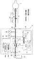
図1に示すように内視鏡システム1は、本発明の第1の実施形態の気腹装置2と、患者3の体腔内の臓器(図1では消化器4)に挿入される軟性の挿入部を有する内視鏡としての軟性内視鏡5と、軟性内視鏡5に照明光を供給する光源装置6と、軟性内視鏡5に設けた撮像素子24に対する信号処理を行う信号処理装置としてのビデオプロセッサ7と、ビデオプロセッサ7により生成された映像信号が入力されることにより、撮像素子24で撮像した画像を内視鏡画像として表示するモニタ8と、を有する。
軟性内視鏡5は、屈曲した体腔内に挿入可能とする軟性の挿入部11と、この挿入部11の後端に設けられ、術者等のユーザが把持して各種の操作を行う操作部12と、この操作部12から延出される可撓性のユニバーサルケーブル13とを有し、ユニバーサルケーブル13の端部のコネクタ14は光源装置6に着脱自在に接続される。Hereinafter, embodiments of the present invention will be described with reference to the drawings.
(First embodiment)
As shown in FIG. 1, an
The
挿入部11は、先端に設けられた先端部15と、先端部15の後端に設けられた湾曲自在の湾曲部16と、湾曲部16の後端から操作部12の前端まで延びる可撓管部17とを有する。
操作部12には、湾曲部16を所望の湾曲方向に湾曲する操作を行う湾曲操作ノブ18が設けてあると共に、送気の操作を行う送気ボタン19と、吸引操作を行う吸引ボタン20とが設けてある。また、操作部12の前端付近には、処置具を挿入する処置具挿入口21が設けてある。上記送気ボタン19は、軟性内視鏡5に設けられた後述する内視鏡送気管路37を閉から開への第1の切替と、開から閉への第2の切替の操作を行う送気切替ボタンの機能を持つ。
光源装置6は、光源装置6の内部で発生した照明光を、軟性内視鏡5のコネクタ14に設けたライトガイドコネクタに供給する。The
The
The
ライトガイドコネクタに供給された照明光は、軟性内視鏡5のユニバーサルケーブル13内等に挿通されたライトガイド22を経て挿入部11の先端部15の照明窓15aから出射され、患部等の被写体を照明する(図1における先端部15付近の拡大図参照)。
先端部15には、照明窓15aに隣接して観察窓15bが設けてあり、この観察窓15bには照明された被写体の光学像を結ぶ対物レンズ23が配置され、この対物レンズ23の結像位置には撮像素子24が配置されている。撮像素子24は、軟性内視鏡5内に挿通された信号線25と、コネクタ14に接続された接続ケーブル26を介してビデオプロセッサ7と接続される。
気腹装置2は、送気するための送気ガス源を構成する炭酸ガスボンベ31と、この炭酸ガスボンベ31が接続管路32を介して接続される気腹装置本体33と、気腹装置本体33により調整された送気ガスを軟性内視鏡5に送気する内視鏡接続チューブ34とを備える。The illumination light supplied to the light guide connector is emitted from the
The
The
気腹装置本体33により調整された送気ガスは、送気口金35に接続された内視鏡接続チューブ34を介して、軟性内視鏡5のコネクタ14の送気口金36と接続され、この送気口金36に連通する(軟性内視鏡5内の)内視鏡送気管路37(拡大図参照)に送気される。
なお、内視鏡送気管路37は、図2において示すようにユニバーサルケーブル13内の内視鏡送気管路37aと、操作部12内における送気ボタン19付近の内視鏡送気管路37bと、挿入部11内における内視鏡送気管路37cとから構成される。
内視鏡送気管路37に送気された送気ガスは、挿入部11の先端部15の先端開口から、挿入部11の先端部15が挿入されているその外部の消化器4内に送気され、送気ガスにより消化器4を膨らませるように気腹する。消化器4を膨らませることにより、消化器4の内部の観察が行い易くなる。
なお、図1においては、1つの軟性内視鏡5を示しているが、例えば点線で示すように、例えばより細径の挿入部11を備えた軟性内視鏡5Bを用いる場合もある。The air supply gas adjusted by the insufflation apparatus
As shown in FIG. 2, the endoscope
The gas supplied to the endoscope
In FIG. 1, one
この軟性内視鏡5Bは、軟性内視鏡5の場合の内視鏡送気管路37よりも、細径の内視鏡送気管路を有する。軟性内視鏡5Bの構成は、軟性内視鏡5の場合とほぼ同様の構成である。また、軟性内視鏡5の場合の内視鏡送気管路37よりも、太径の内視鏡送気管路を有する軟性内視鏡が内視鏡検査に用いられる場合もある(図示せず)。
図2は気腹装置2及び気腹装置本体33内部の構成を示す。
図2に示すように送気ガス源を構成する炭酸ガスボンベ31に接続される接続管路32は、気腹装置本体33の筐体の内部の気腹用送気管路41の一方の端部に接続され、他方の端部は送気口金35に至る。なお、気腹用送気管路41の一方の端部を気腹装置本体33の筐体の外部に突出させ、接続管路32を用いることなく炭酸ガスボンベ31に接続する構造にしても良い。
この気腹用送気管路41上には、以下のように減圧器42、流量調整部(又は流量調整器)43、電磁弁44、圧力センサ45及び流量センサ46が配置されている。また、流量調整部43、電磁弁44、圧力センサ45及び流量センサ46は、点線で示すように電気制御基板47と信号線で接続されている。This
FIG. 2 shows the internal configuration of the
As shown in FIG. 2, the
A
また、気腹装置本体33に設けたタッチパネル48には、送気の開始と停止の指示操作を行う送気ボタン48aと、気腹に適した送気流量としての設定流量を設定する流量設定部48bが設けてある。ユーザにより、送気ボタン48aの指示操作の信号は信号線を介して電気制御基板47に送られ、電気制御基板47は、指示操作に対応した制御動作を行う。また、電気制御基板47は、流量センサ46により測定された測定流量が、流量設定部48bにより設定された目標とする設定流量となるように流量調整部43による送気流量を調整する制御動作を行う。
減圧器42は、炭酸ガスボンベ31から送気される送気ガスとしての炭酸ガスの圧力を減圧して、流量調整部43に送気する。流量調整部43は、気腹用送気管路41により送気される送気ガスの流量(送気流量)を調整する。この流量調整部43は、図3に示すように例えば、制御信号の電圧レベルに比例して入力される送気ガスの圧力を無段階に制御することにより、送気ガスの送気流量を調整する電空比例弁43aにより構成される。
The
The
流量調整部43により調整された送気ガスは、電気制御基板47からの弁開閉信号により開閉が制御される電磁弁44を経て送気口金35側に送気される。また、電磁弁44と送気口金35との間の気腹用送気管路41上には、送気ガスの圧力を測定する圧力センサ45と、送気流量を測定する流量センサ46とが配置され、それぞれ測定した送気圧力(測定圧力とも言う)及び測定した送気流量(測定流量とも言う)を電気制御基板47に送る。
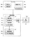
電気制御基板47は、例えば図3に示すように中央演算処理装置(CPUと略記)51と、CPU51から流量調整部43を構成する電空比例弁43aの送気圧力を制御するデジタル電圧値をアナログ電圧値に変換して出力するD/A変換器52と、CPU51の制御プログラムを記憶すると共に、測定流量が設定流量と等しくなる場合における電空比例弁43aの送気圧力値に対応する値を調整値として記憶するメモリ53とを有する。
The air supply gas adjusted by the flow
For example, as shown in FIG. 3, the
なお、軟性内視鏡5の内視鏡送気管路37は、操作部12内の送気ボタン19を押し下げる操作を行うことにより、開状態となり、送気ボタン19を押し下げる操作を行わないか、押し下げた指を送気ボタン19から離す操作を行うと、閉状態となる。図2においては、指で送気ボタン19を押し下げた開状態の場合で示している。 具体的には、図4Aに示すように送気ボタン19の両側の内視鏡送気管路37に連通するように対向する位置に開口55a、55bがそれぞれ設けたシリンダ55内には、円柱形状の送気ボタン19が、その長手方向にスライド自在に配置され、また、送気ボタン19は、シリンダ55の段差状に細径にされた底部側に配置したバネ56により、シリンダ55の上端の開口から突出する方向に付勢されている。
また、送気ボタン19にも、その長手方向の中央位置付近に、横孔19aが設けてあるが、図4Aに示すように開口55a,55bと横孔19aとは連通しない状態、それぞれ閉塞された状態に保持されている。It should be noted that the endoscope
Further, the
図4Aの状態において、指57で送気ボタン19が段差部に当接する位置まで押し下げる操作を行うと、図4Bに示すように開口55a,55bと横孔19aとは連通する状態となる。このように送気ボタン19を操作することにより、内視鏡送気管路37を閉塞状態と開状態に設定することができる。
このため、気腹装置本体33に設けた送気ボタン48aをONにしても、軟性内視鏡5の送気ボタン19がONにされていないと、実質的には気腹対象の部位(消化器4)に送気することができない。
気腹装置本体33に設けた送気ボタン48aがONにされた状態において、軟性内視鏡5の送気ボタン19がONにされた場合には、送気動作が実質的に開始し、測定流量が0の状態から増加する。
本実施形態においては、測定流量が0の状態から変化した場合、CPU51は、測定流量が予め設定された設定流量と比較する。このため、図3に示すようにCPU51は、流量センサ46により測定された測定流量と、設定流量とを比較する流量比較部(又は流量比較回路)51aの機能を有する。In the state of FIG. 4A, when an operation of pushing down the
For this reason, even if the
When the
In the present embodiment, when the measured flow rate is changed from 0, the
流量比較部51aは、比較回路により構成される。なお、図3において点線で示す変化量判定部51bは、後述する第2の実施形態において用いられる。
CPU51は、流量比較部51aによる比較結果に応じて流量調整部43を構成する電空比例弁43aによる流量を調整する調整値としての送気圧力値をステップ状に調整し、設定流量と等しい値になるように制御する。換言すると、CPU51に制御される流量調整部43(の電空比例弁43a)は、測定流量が設定流量に等しくない場合には、調整値を変更して(内視鏡送気管路37への)送気流量を調整する送気流量調整部(又は送気流量調整器)を構成する。
この場合、CPU51は、流量センサ46の測定流量と設定流量との比較結果として両流量が等しくない場合において、測定流量が設定流量より小さい場合には、測定流量を増大させるように電空比例弁43aの送気圧力値を増大させ、逆に測定流量が設定流量より大きい場合には、測定流量を減少させるように電空比例弁43aの送気圧力値を減少させるように制御する。The flow
The
In this case, when the two flow rates are not equal as a comparison result between the measured flow rate of the
なお、CPU51は、流量センサ46により測定される測定流量が設定流量に達した後、0の測定流量となる状態では、流量調整部43の流量調整の動作を停止させ、測定流量が0以外となる状態(測定流量が0より大きい状態)では、流量調整部43が流量調整の動作を行うように制御する。CPU51は、測定流量が0となる状態を、測定流量と、0より僅かに大きい閾値と比較し、測定流量が該閾値以下である場合に測定流量が0であることを検出する。
また、本実施形態においては、流量比較部51aにより、流量センサ46の測定流量が設定流量に等しい比較結果の場合には、CPU51は、流量調整部43(の電空比例弁43a)の調整値をメモリ53に記憶させる。このため、メモリ53は、測定流量が設定流量に等しい比較結果の場合に、流量調整部43の調整値を記憶する調整値記憶部(調整値記憶デバイス)53a又は送気圧力値記憶部(送気圧力値記憶デバイス)の機能を有する。The
In the present embodiment, when the flow
また、本実施形態においては、流量センサ46の測定流量が0と等しい場合には、CPU51は、メモリ53によって構成される調整値記憶部53aから読み出した上記調整値を、送気流量調整部を構成する流量調整部43の電空比例弁43aにおける現在以降に用いる調整値に設定する制御を行う。換言すると、流量センサ46の測定流量が0と等しい場合には、CPU51は、流量調整部43において設定されている調整値を、調整値記憶部53aより読み出した送気圧力値としての調整値に(更新するように)設定する制御を行う制御部(又は制御回路)の機能を有する。
上記CPU51による制御部の機能を補足説明する。上述した構成から分かるように軟性内視鏡5の送気ボタン19をON又はOFFした場合、電気信号を発生しない構成であるために気腹装置本体33側の制御手段を構成する電気制御基板47は、送気ボタン19がONの状態からOFFにされた直後においては、送気流量調整部を構成する流量調整部43が送気流量を調整する動作を続行し、測定流量が設定流量から変化した場合(この場合、内視鏡送気管路37が閉状態になるために測定流量は0に向かって減少する)には、設定流量に対応する調整値の状態から変化させてしまう。In this embodiment, when the measured flow rate of the
The function of the control unit by the
このように変化させてしまうと、次に送気ボタン19をOFFからONにした場合、望ましい調整値から変化した調整値を用いて送気流量を調整する動作を行う(動作を開始する)ことになってしまう。
本実施形態においては、上記のように流量センサ46の測定流量が0と等しい場合(換言すると、測定流量が0よりも僅かに大きい閾値以下に変化した場合)には、軟性内視鏡5の送気ボタン19がONからOFFにされて内視鏡送気管路37が閉状態に設定(又は開から閉への切替が)されたことを測定流量に基づいて検出する。 そして、このように内視鏡送気管路37が閉状態に設定されたことを検出した場合には、(測定流量が設定流量に等しい場合の調整値を記憶した)調整値記憶部53aより読み出した調整値を、流量調整部43の電空比例弁43aに設定する。このように設定することにより、次に送気ボタン19をOFFからONにした場合、設定流量に対応する調整値を初期値(初期設定値)として流量調整部43の送気流量を調整する動作を開始させることができるようにする。If the
In the present embodiment, as described above, when the measured flow rate of the
本実施形態の気腹装置2は、送気するための送気ガス源としての炭酸ガスボンベ31と、前記送気ガス源と(接続管路32を用いて、又は接続管路32を用いることなく)接続され、気腹用の送気ガスを送気する気腹用送気管路41と、前記気腹用送気管路41と軟性の挿入部11を有する内視鏡としての軟性内視鏡5内に設けられた内視鏡送気管路37とを接続する内視鏡接続チューブ34と、前記気腹用送気管路41上に設けられ、前記送気流量を測定流量として測定するよう構成された送気流量測定部としての流量センサ46と、前記送気流量測定部により測定される前記送気流量を目標とする設定流量とするために予め前記設定流量を設定するよう構成された設定流量設定部を形成する流量設定部48bと、前記気腹用送気管路41上に設けられ、前記送気流量測定部により測定された測定流量が前記設定流量に等しくない場合には、前記送気流量の調整値を変更して前記内視鏡送気管路37への前記送気流量を調整するよう構成された送気流量調整部を形成する流量調整部43と、前記送気流量測定部により測定された測定流量が前記設定流量と等しいときに、前記送気流量調整部の前記調整値を記憶するよう構成された調整値記憶部53aを有する記憶デバイスとしてのメモリ53と、前記送気流量測定部により測定された前記測定流量が前記設定流量に達した後において閾値以下に変化したとき(本実施形態においては0に等しい値に変化したとき)には、前記調整値記憶部より読み出した前記調整値を送気流量調整部に設定する制御を行うよう構成された制御部を形成するCPU51と、を有することを特徴とする。
The
次に本実施形態の動作を説明する。図5は、気腹装置2の全体的な動作のフローチャートを示し、図7はタイミングチャートを示す。
図5に示すように送気処理を開始すると、最初のステップS1においてユーザはタッチパネル48の流量設定部48bを操作して、気腹する場合における所望とする送気流量値等の目標とする設定流量を設定する。その後、タッチパネル48の送気ボタン48aをONすることにより、ステップS2に示すようにCPU51は、電磁弁44を開き、送気動作を開始する。なお、以前に設定流量が設定されており、以前の設定流量を用いる場合には、ステップS1の処理を省くことができる。
また、ユーザは軟性内視鏡5の送気ボタン19をONすることにより、送気動作が実質的に開始する。
ステップS3に示すようにCPU51は、ステップS2の処理後、少しの時間(例えば100mS)待つ。Next, the operation of this embodiment will be described. FIG. 5 shows a flowchart of the overall operation of the
When the air supply process is started as shown in FIG. 5, in the first step S1, the user operates the flow
The user substantially turns on the air supply operation by turning on the
As shown in step S3, the
少しの時間経過後、ステップS4に示すように流量センサ46は送気流量を測定する。換言すると、CPU51はステップS3から少し時間が経過した後において流量センサ46により測定された送気流量を測定流量として取得する。
次のステップS5においてCPU51は、測定流量が0の送気流量としての0L/minか否かの判定を行う。軟性内視鏡5の送気ボタン19がONにされている場合には、測定流量は0以外の正の値を持つ。
測定流量が0でない判定結果の場合には、次のステップS6においてCPU51は、測定流量がステップS1において設定された設定流量と等しいかの判定を行う。送気ボタン48a、19をONにして実質的に送気動作が開始後からの時間経過が小さい場合には、測定流量は設定流量に達していない。この場合には、CPU51は、測定流量が設定流量と等しくないと判定する。
測定流量が設定流量と等しくない判定結果の場合には、次のステップS7においてCPU51は、流量調整部43で流量調整を行うように制御する。ステップS7の処理は図6を参照して後述する。After a short time has elapsed, the
In the next step S5, the
If the measurement flow rate is not 0, in the next step S6, the
In the case of a determination result that the measured flow rate is not equal to the set flow rate, in the next step S <b> 7, the
ステップS7の処理後、ステップS3の処理に戻る。ステップS3〜S7の処理を繰り返すことにより、測定流量が設定流量に等しくなる。測定流量が設定流量に等しくなった場合には、ステップS6において、CPU51は測定流量が設定流量に等しいと判定し、ステップS8の処理に進む。
ステップS8においてCPU51は、メモリ53に現在の流量調整部43の調整値(つまり、測定流量が設定流量に等しい場合の流量調整部43の調整値)を記憶するように制御する。また、CPU51は、測定流量が設定流量に等しい場合の調整値を保持するように流量調整部43の流量調整を制御する。この状態においては、流量調整部43の調整値は、設定流量に対応した一定の送気圧力設定値の状態となる(図7の送気圧力設定値参照)。
ステップS8の処理の後、ステップS3の処理に戻る。測定流量が設定流量に等しい状態にて、消化器4内が送気ガスとしての炭酸ガスにより十分に気腹されると、ユーザは送気を停止するために送気ボタン19をONからOFFにすると、内視鏡送気管路37は開状態から閉状態になる。After step S7, the process returns to step S3. By repeating the processes of steps S3 to S7, the measured flow rate becomes equal to the set flow rate. When the measured flow rate becomes equal to the set flow rate, in step S6, the
In step S8, the
After step S8, the process returns to step S3. When the measured flow rate is equal to the set flow rate and the digester 4 is sufficiently inhaled by carbon dioxide gas as the air supply gas, the user turns the
この場合には、送気ボタン19をOFFにした後の短い時間経過後に、流量センサ46で測定された測定流量が0になる。すると、ステップS5においてCPU51は、(0に近い閾値以下となることにより)測定流量が0に等しいと判定する。測定流量が0に等しい判定結果の場合には、ステップS9においてCPU51は、メモリ53からこのメモリ53に記憶された調整値を読み出し、読み出した調整値を流量調整部43に設定する。
具体的には、メモリ53に記憶されたデジタルの調整値が例えばVaであった場合には、この調整値VaをD/A変換器52で変換したアナログの調整値Vaを流量調整部43の電空比例弁43aに設定する。また、CPU51は、電空比例弁43aによる流量調整の動作を停止するように制御する。流量調整部43の電空比例弁43aは、(次に)送気流量を調整する動作を行う場合、この調整値Vaを初期値として送気流量の調整を開始することになる。
In this case, the measured flow rate measured by the
Specifically, when the digital adjustment value stored in the
ステップS9の処理の後(少しの時間経過したら)次のステップS10において流量センサ46は送気流量を測定する。そして、CPU51は、測定された送気流量(つまり測定流量)を取得する。
次のステップS11においてCPU51は、取得された測定流量が0であるか否かを判定する。測定流量が0である場合には、ステップS11の処理を続行する。
一方、ユーザが送気ボタン19をOFFにした後、再びONにして送気を再開する場合がある。このような場合には、測定流量は0より大きな値となるため、ステップS11においてCPU51は、測定流量が0でないと判定する。この判定結果の場合には、CPU51は、流量調整部43の電空比例弁43aによる流量調整の動作をONにしてステップS3の処理に戻り、上述した動作を繰り返す。
ステップS3に戻って、上述した動作を繰り返す場合、流量調整部43の電空比例弁43aは、ステップS11の前のステップS9においてメモリ53に記憶されている調整値に設定された状態で送気動作を開始することになる。この場合には、より望ましい調整値の状態から送気動作を行うことができる。After the process in step S9 (after a short time has elapsed), in the next step S10, the
In the next step S11, the
On the other hand, after the user turns off the
When returning to step S3 and repeating the above-described operation, the electropneumatic
図6は、ステップS7の処理の詳細を示す。以下の説明においては、ステップS7の処理を開始した場合における流量調整部43の電空比例弁43aの調整値がVaであるとする。なお、電空比例弁43aは、調整値Vaに比例して送気圧力設定値が変化して、送気流量を調整する。流量調整の処理が開始すると、最初のステップS21において、CPU51は流量センサ46により測定された測定流量が設定流量より大きいか否かを判定する。
測定流量が設定流量より小さい判定結果の場合には、次のステップS22においてCPU51は、調整値Vaを所定値Δだけ大きくする。つまり、CPU51は、調整値VaをVa+Δに設定した後、ステップS3の処理に移る。この場合には、送気圧力を増大することにより、送気流量が増大する。
そして、増大後において、ステップS6において、測定流量が設定流量に等しくなく、さらにステップS21において測定流量が設定流量より小さい場合には、次のステップS22においてCPU51は、調整値Va+Δから更に所定値Δだけ大きくする。このように送気流量を調整する制御ループにより、測定流量を設定流量に等しくなるように短時間で設定することができる。FIG. 6 shows details of the process in step S7. In the following description, it is assumed that the adjustment value of the electropneumatic
If the measurement flow rate is smaller than the set flow rate, the
After the increase, if the measured flow rate is not equal to the set flow rate in step S6, and if the measured flow rate is smaller than the set flow rate in step S21, in the next step S22, the
一方、ステップS21において測定流量が設定流量よりも大きい判定結果の場合には、ステップS23においてCPU51は、現在の調整値Vaから所定値Δだけ小さくする。つまり、CPU51は、調整値VaをVa−Δに設定した後、ステップS3の処理に移る。
この場合には、送気圧力設定値を小さくすることにより、送気流量が減少する。そして、減少後において、ステップS6において、測定流量が設定流量に等しくなく、さらにステップS21において測定流量が設定流量より大きい場合には、ステップS23においてCPU51は、調整値Va−Δから更に所定値Δだけ小さくする。
このように送気流量を調整する制御ループにより、測定流量を設定流量に等しくなるように短時間で設定することができる。なお、上述したように測定流量が設定流量に等しくなった場合には、ステップS8に示すように測定流量が設定流量に等しくなった場合における流量調整部43の電空比例弁43aに設定されている調整値をメモリ53に記憶する。On the other hand, if it is determined in step S21 that the measured flow rate is greater than the set flow rate, in step S23, the
In this case, the air flow rate is reduced by reducing the air pressure setting value. After the decrease, if the measured flow rate is not equal to the set flow rate in step S6, and if the measured flow rate is greater than the set flow rate in step S21, the
Thus, the measurement flow rate can be set in a short time to be equal to the set flow rate by the control loop for adjusting the air supply flow rate. As described above, when the measured flow rate becomes equal to the set flow rate, the electropneumatic
図7は気腹装置2のタイミングチャートを示し、横軸が時間tの経過を示す。図7に示すように気腹装置本体33のタッチパネル48の送気ボタン48aを例えば時間t0においてOFFからONにすると、CPU51は電磁弁44を開き、(気腹装置本体33側での)送気動作を開始する。また、電空比例弁43aは、例えば初期動作の際の調整値に対応する送気圧力設定値(図7ではデフォルト送気圧力設定値)Pdになる。なお、図7に示す送気圧力設定値は、圧力センサ45により測定された電空比例弁43a付近の気腹用送気管路41内の値とは異なる。
ユーザが例えば時間t1において軟性内視鏡5の送気ボタン19をOFFからONにする操作を行うと、内視鏡送気管路37は閉状態から開状態になり、電空比例弁43aの送気圧力設定値Pdで気腹装置本体33の気腹用送気管路41を通った送気ガスは、内視鏡送気管路37を通って消化器4内に送気される。FIG. 7 shows a timing chart of the
For example, when the user performs an operation of turning the
送気ボタン19をONした時間t1直後付近においては、流量センサ46により測定される測定流量は0から増加する。測定流量が設定流量に達していない場合には、図6において説明したようにCPU51は電空比例弁43aの調整値を変化させて送気流量を調整する。
測定流量は0から増加する場合には、調整値がステップ状に大きく変化し、送気圧力もステップ状(図7ではステップの値が小さいため直線状)に大きくなる。
図7に示すように測定流量が設定流量に達していない期間(時間t1からt2)においては、送気圧力設定値が増大する。そして、測定流量が設定流量に達した時間t2において、図5のステップS8で説明したようにCPU51は、電空比例弁43aの現在の調整値をメモリ53に記憶するように制御する。In the vicinity of time t1 immediately after the
When the measured flow rate increases from 0, the adjustment value changes greatly in steps, and the air supply pressure also increases in steps (in the form of a straight line because the step value is small in FIG. 7).
As shown in FIG. 7, in the period (time t1 to t2) when the measured flow rate does not reach the set flow rate, the air supply pressure set value increases. Then, at time t2 when the measured flow rate reaches the set flow rate, the
また、CPU51は、測定流量が設定流量に等しい状態における電空比例弁43aの現在の調整値を保持するように制御する。従って、時間t2以後における送気圧力設定値は、一定の送気圧力設定値Paとなる。この送気圧力設定値Paは、測定流量が設定流量に等しい状態の電空比例弁43aの調整値に相当する。なお、図7に示すように測定流量が設定流量に等しい状態が継続している期間(t2〜t3)、CPU51は、電空比例弁43aの現在の調整値をメモリ53に記憶する制御を短い時間間隔で行う。換言すると、メモリ53に記憶されている調整値は、時間的に新しい調整値で上書きされてメモリ53に保持される。
時間t2以後における時間t3においてユーザが送気ボタン19をONからOFFにすると、内視鏡送気管路37は開から閉状態になり、流量センサ46により測定される送気流量としての測定流量は急激に低下し、時間t3直後の短い時間後の時間t4において0となる。時間t3直後においては、CPU51による流量調整機能は動作状態(図7においてON)である。Further, the
When the user turns the
そのため、CPU51は、流量センサ46の測定流量が設定流量よりも小さい値になると、電空比例弁43aの調整値としての送気圧力設定値Paから増大させるように制御する。そして、図7に示すように送気圧力設定値は時間t3からt4まで増大する。時間t4での送気圧力設定値をP4で示している。
そして、時間t4において測定流量が0近傍になると、CPU51は、図5のステップS9において説明したように電空比例弁43aによる流量調整の動作を停止させ、メモリ53より調整値を読み出し、この調整値を電空比例弁43aに設定する。
なお、この調整値は、図7における時間t3での調整値となり、その場合の送気圧力設定値はPaに相当する。従って、時間t4以後に送気ボタン19が再びONにされると、電空比例弁43aは送気圧力設定値はPaを初期値として流量調整を開始する。Therefore, when the measured flow rate of the
When the measured flow rate becomes close to 0 at time t4, the
This adjustment value is the adjustment value at time t3 in FIG. 7, and the air supply pressure setting value in this case corresponds to Pa. Accordingly, when the
このように動作する本実施形態によれば、測定流量を設定流量と比較して、測定流量が設定流量に等しくなるように流量の調整を行うようにしているので、軟性内視鏡5の内視鏡送気管路37の内径が異なったり、その長さが異なるような場合においても、所望の流量としての設定流量で送気することができる。従って、ユーザによる送気流量を調整する手間を軽減して、操作性の良い気腹装置2を提供できる。
また、本実施形態によれば、測定流量が0以外の場合には流量調整部43による流量調整を動作させ、また測定流量が設定流量に等しい状態の流量調整部43の調整値を調整値記憶部53aに記憶し、その後に測定流量が0になった場合には流量調整部43による流量調整を停止し、かつ調整値記憶部53aより読み出した調整値を流量調整部43を電空比例弁43aに設定するようにしているので、次に流量調整を開始する場合には調整値記憶部53aに記憶された調整値を初期値として流量調整を行うことができる。
なお、本実施形態においては、流量調整部43を電空比例弁43aを用いて構成した場合を説明しているが、電空比例弁43aの場合に限定されるものでなく、電気信号により、流量を調整することが可能な調整弁であれば良い。According to this embodiment that operates in this way, the measured flow rate is compared with the set flow rate, and the flow rate is adjusted so that the measured flow rate becomes equal to the set flow rate. Even in the case where the inner diameter of the endoscope
Further, according to the present embodiment, when the measured flow rate is other than 0, the flow
In addition, in this embodiment, although the case where the flow
(第2の実施形態)
次に本発明の第2の実施形態を説明する。本実施形態は、一定の時間間隔において測定流量が閾値を超えて変化した場合、より具体的には閾値を超えて測定流量が下がった場合には、軟性内視鏡5の送気ボタン19がONからOFFにされたことを検出し、流量調整部43の流量調整の動作を停止させる。
このため、本実施形態においては、第1の実施形態においてCPU51は、流量センサ46による測定流量を一定の時間間隔Δtで取得し、一定の時間間隔Δtにおいての測定流量の変化量が閾値Fthを超えて下がったか否かを判定する変化量判定部(変化量判定器)51b又は流量変化量判定部(流量変化量判定器)51b(図3において点線で示す)を備える。そして、CPU51の比較回路により構成される変化量判定部51bは、閾値Fthを超えて下がった判定結果の場合には、流量調整部43の電空比例弁43aの流量調整の動作を停止させる。
第1の実施の形態においては、図7において説明したように送気ボタン19をOFFにした場合の直後においては、電空比例弁43aの流量調整の動作が停止しないために、調整値を変化させ、従って送気圧力設定値も変化する。(Second Embodiment)
Next, a second embodiment of the present invention will be described. In the present embodiment, when the measured flow rate changes beyond the threshold value at a certain time interval, more specifically, when the measured flow rate falls below the threshold value, the
For this reason, in this embodiment, in the first embodiment, the
In the first embodiment, as described with reference to FIG. 7, immediately after the
送気ボタン19をONからOFFにした場合の直後においては、内視鏡送気管路37は開状態から閉状態に変化するために送気流量が急激に下がるように変化する。本実施形態は、送気ボタン19をONからOFFにした場合の直後の送気流量が急激に下がる変化を上記変化量判定部51bにより検出又は判定して、流量調整部43の流量調整の動作を速やかに停止させることを目的とする。
このため、上記閾値Fthは、図7における時間間隔t3〜t4において設定流量程度に測定流量が変化する状態を検知できるように設定する。つまり、閾値Fthは、流量センサ46が送気流量を測定する短い時間間隔をΔtとした場合、Fs×Δt/(t4−t3)の値よりも若干小さな値に設定される。ここで、Fsは設定流量の値を示す。その他の構成は、第1の実施形態と同様であり、その説明を省略する。Immediately after the
For this reason, the threshold value Fth is set so as to detect a state in which the measured flow rate changes to about the set flow rate at time intervals t3 to t4 in FIG. That is, the threshold value Fth is set to a value slightly smaller than the value of Fs × Δt / (t4−t3), where Δt is a short time interval in which the
図8は本実施の形態における送気処理を示す。図8に示す送気処理は、図5の送気処理と一部が異なるのみであり、異なる部分のみ説明する。図8の送気処理は、図5におけるステップS5の処理をステップS31のように変更し、図5におけるステップS9〜S11の処理をステップS32、S10,S11,S33のように変更した内容となる。
図8に示すようにステップS1からS4までは、図5の場合と同様の処理を行い、ステップS4の処理の後のステップS31においてCPU51(の変化量判定部51b)は、流量センサ46により測定された現在の測定流量が、(Δtだけ前となる)直前に測定した測定流量から閾値Fthを超えて下がる変化をしているか否かの判定を行う。送気ボタン19がONにされた状態においては、上記の測定流量が閾値Fthを超えて下がる変化をしない。そして、CPU51(の変化量判定部51b)が、変化なしの判定をした場合には、ステップS6の処理に進み、図5において説明した処理が行う。そして、測定流量が設定流量に等しくなるように流量調整の処理が行われる。FIG. 8 shows an air supply process in the present embodiment. The air supply process shown in FIG. 8 is only partially different from the air supply process of FIG. 5, and only the different parts will be described. The air supply process in FIG. 8 has the contents obtained by changing the process in step S5 in FIG. 5 as in step S31 and changing the processes in steps S9 to S11 in FIG. 5 as in steps S32, S10, S11, and S33. .
As shown in FIG. 8, from step S1 to step S4, the same processing as in FIG. 5 is performed, and in step S31 after the processing of step S4, the CPU 51 (change
測定流量が設定流量に等しくなった状態で消化器4内を送気ガスで十分に気腹し、ユーザは送気を停止するために送気ボタン19をONからOFFにする。この場合には、図7及び図9に示すように測定流量は急激に下がる。
すると、ステップS31の判定処理において上記の測定流量が閾値Fthを超えて下がる変化有りの判定結果となり、この判定結果の場合には、ステップS32の処理に進み、このステップS32においてCPU51は、流量調整部43の電空比例弁43aによる送気流量の調整動作を停止させる。
図9は本実施形態におけるタイミングチャートを示す。図9にタイミングチャートは、図7のタイミングチャートにおいて、時間t3〜t4の期間における動作のみが異なる。上記のように時間t3直後に測定流量が急激に下がる変化が変化量判定部51bにより判定(検知)され、CPU51は電空比例弁43aによる送気流量の調整動作を停止させる。In the state where the measured flow rate is equal to the set flow rate, the digester 4 is sufficiently inflated with the air supply gas, and the user turns the
Then, in the determination process of step S31, the above-described measurement flow rate becomes a determination result with a change that falls below the threshold value Fth, and in the case of this determination result, the process proceeds to step S32, and in this step S32, the
FIG. 9 shows a timing chart in the present embodiment. The timing chart in FIG. 9 is different from the timing chart in FIG. 7 only in the operation in the period of time t3 to t4. As described above, the
このため、図7においては時間t3直後に調整値となる送気圧力設定値が上昇する現象を、図9においては停止させ、時間t3直後に調整値としての送気圧力設定値は変化しない。
図8におけるステップS32の処理の次のステップS10において流量センサは、送気流量を測定し、CPU51は、測定流量を取得する。そして、次のステップS11においてCPU51は、測定流量が0か否かを判定し、測定流量が0の場合にはステップS33において図5のステップS9と同様にメモリ53より調整値を読み出し、読み出した調整値を流量調整部43の電空比例弁43aに設定する。その後、ステップS10の処理に戻る。そして、CPU51は、測定流量が0以外になるのを待つ状態となる。送気ボタン19がOFFにされた後、ユーザが再び送気を開始するために送気ボタン19をOFFからONにすると、ステップS11においてCPU51は測定流量が0でない判定を行い、流量調整部43の流量調整の動作を再開してステップS3の処理に戻る。For this reason, the phenomenon in which the air supply pressure setting value that becomes the adjustment value immediately after time t3 in FIG. 7 is stopped in FIG. 9, and the air supply pressure setting value as the adjustment value does not change immediately after time t3.
In step S10 next to the process of step S32 in FIG. 8, the flow rate sensor measures the air supply flow rate, and the
第1の実施形態においては図7に示すように、送気ボタン19がONされた時間t1から、送気ボタン19がONからOFFにされた後の測定流量が0になる時間t4までの期間t4−t1が流量調整を行う流量調整機能の状態となる。
これに対して、本実施形態においては、図9に示すように送気ボタン19がONされた時間t1から、送気ボタン19がONからOFFにされた時間t3までの期間t3−t1が流量調整を行う流量調整機能の状態となる。
本実施形態は、第1の実施形態と同様の効果を有すると共に、送気ボタン19がONからOFFにされた直後における無駄に流量調整を行う動作を解消できる。
なお、上述の説明においては、CPU51の変化量判定部51bは、Δtの時間間隔後の測定流量の変化量(差分)が、正の閾値Fthを超えて下がった判定結果の場合にのみ、流量調整部43の電空比例弁43aの流量調整の動作を停止させると説明したが、閾値Fthを正負の値に設定して、閾値を超える変化の有無を判定を行うようにしても良い。例えば、Δtの時間間隔後の測定流量の変化量(差分)が、±Fthを超えた場合に、流量調整の動作を停止させるようにしても良い。
具体的には、±Fth=±0.5L/minに設定しても良い。但し、図7における時間t1〜t2の期間における測定流量が増大する変化の場合を含まない値となるように設定すべきである。In the first embodiment, as shown in FIG. 7, the period from time t1 when the
On the other hand, in the present embodiment, as shown in FIG. 9, the flow rate is from the time t1 when the
This embodiment has the same effect as that of the first embodiment, and can eliminate the wasteful adjustment of the flow rate immediately after the
In the above description, the change
Specifically, ± Fth = ± 0.5 L / min may be set. However, it should be set to a value that does not include the case where the measured flow rate increases during the period of time t1 to t2 in FIG.
(第3の実施形態)
次に本発明の第3の実施形態を説明する。本実施形態は、例えば第1の実施形態において、タッチパネル48に流量補正ボタン(又は流量調整ボタン)48cを設け、手術等の手技を実地する前に、流量調整部43の調整値を手技に用いる軟性内視鏡5に適した調整値に補正し、手技中での流量調整処理をより円滑に行うことができるようにする。
図10は本実施形態における気腹装置2Cを示す。この気腹装置2Cは、図2の気腹装置2において、タッチパネル48に更に流量補正ボタン48cが設けてあり、流量補正ボタン48cが操作された場合の操作信号はCPU51に入力される。
本実施形態においては、この流量補正ボタン48cが操作された場合には、CPU51は流量補正ボタン48cが操作されたことを検知して、流量調整部43による流量補正処理又は流量調整処理を行う。そして、制御部を形成するCPU51は、流量補正処理又は流量調整処理により測定流量が設定流量と等しいときの調整値をメモリ53の調整値記憶部53aに記憶するように制御し、その後、実際に流量調整部43が流量調整を開始する場合に調整値記憶部53aが記憶した調整値を用いるように制御する。(Third embodiment)
Next, a third embodiment of the present invention will be described. In the present embodiment, for example, in the first embodiment, a flow rate correction button (or a flow rate adjustment button) 48c is provided on the
FIG. 10 shows an insufflation apparatus 2C in the present embodiment. In this insufflation apparatus 2C, in the
In the present embodiment, when the flow
その他の構成は、第1の実施形態と同様であり、その説明を省略する。上記流量補正ボタン48cは、送気流量調整部としての流量調整部43に対して、内視鏡送気管路37への送気流量を調整する動作を開始させる操作を行う流量調整操作部(又は流量調整操作デバイス)を形成する。
Other configurations are the same as those in the first embodiment, and a description thereof will be omitted. The flow
図11は、流量補正ボタン48cが操作された場合における流量補正処理を示す。
なお、ユーザは、流量補正ボタン48cを操作する場合、軟性内視鏡5を患者3の体腔内に挿入する前に、操作する。図11に示す流量補正処理は、図5におけるステップS1〜S8の処理に類似している。また、流量補正ボタン48cを操作する前にユーザにより予め設定流量が設定されているとして説明する。
流量補正ボタン48cが操作されると、最初のステップS41においてCPU51は、電磁弁44を開き、送気の動作を開始する。また、ユーザは送気ボタン19もONにする。次のステップS42においてCPU51は、少しの時間(例えば100mS)待つ。
少しの時間経過後、ステップS43に示すように流量センサ46は送気流量を測定する。そしてCPU51は流量センサ46により測定された送気流量を測定流量として取得する。FIG. 11 shows a flow rate correction process when the flow
The user operates the flow
When the flow
After a short time has elapsed, the
次のステップS44においてCPU51は、測定流量が設定流量に等しいか否かの判定を行う。現在の動作状況においては、測定流量が設定流量に達していないためにCPU51は、測定流量が設定流量に等しくないと判定し、次のステップS45においてCPU51は、流量調整部43の電空比例弁43aが流量調整を行うように制御する。この流量調整の処理として、図6におけるステップS21,S22の処理を行い、ステップS42の処理に戻る。
このような制御ループにより、調整値がステップ状に増大することにより、測定流量もステップに増大して設定流量に達する。すると、ステップS44においてCPU51は、測定流量が設定流量に等しくなったと判定し、ステップS46の処理に移る。このステップS46においてCPU51はメモリ53に、測定流量が設定流量に等しくなったときの調整値を記憶し、図11の流量補正処理を終了する。
In the next step S44, the
By such a control loop, the adjustment value increases stepwise, so that the measured flow rate also increases stepwise and reaches the set flow rate. Then, in step S44, the
図11の流量補正処理により、流量調整部43の電空比例弁43aが流量調整の動作を開始する場合の調整値の初期値(初期設定値)を、流量補正処理を行わない場合よりも円滑に設定流量に設定して気腹することができる。
上記のように流量補正処理を行った後、軟性内視鏡5の挿入部11を患者3の体腔内、例えば消化器4内に挿入し、送気ボタン48aを操作して実際の手技での送気を開始する。図12は本実施形態における送気処理を示す。図12に示すフローチャートは、図5の送気処理において、ステップS8の処理を省略した内容となる。このため、図12においては、図5の送気処理において省略されるステップS8の処理を点線で示している。
上述したように本実施形態においては、流量補正処理により測定流量が設定流量に等しくなったときの調整値をメモリ53に記憶しているので、図12の送気処理においては、調整値をメモリ53に記憶する処理を行わない。その他の処理は、図5の場合と同様である。By the flow rate correction process of FIG. 11, the initial value (initial setting value) of the adjustment value when the electropneumatic
After performing the flow rate correction processing as described above, the
As described above, in the present embodiment, since the adjustment value when the measured flow rate becomes equal to the set flow rate by the flow rate correction process is stored in the
本実施の形態によれば、第1の実施形態の効果を有すると共に、更に実際の手技を行う前に、手技に用いる軟性内視鏡5を用いた流量補正処理により流量調整部43が流量調整の動作を開始する調整値を、設定流量に設定しているので、実際に軟性内視鏡5を用いて手技を行う場合、送気流量(測定流量)を設定流量に設定して気腹を円滑に行うことができる。
なお、上記のように流量補正を行う代わりに、実際に接続して使用する軟性内視鏡5や、ビデオプロセッサ7から、当該軟性内視鏡5の内視鏡送気管路37の情報を含む内視鏡情報を取得し、取得した内視鏡情報における内視鏡送気管路37の情報に基づいて、上記の調整値を設定するようにしても良い。According to the present embodiment, the flow
In addition, instead of performing flow rate correction as described above, information on the
(第4の実施形態)
次に本発明の第4の実施形態を説明する。第1の実施形態においては、測定流量が設定流量に達した後において、送気ボタン19がONからOFFにされて測定流量が設定流量から0になるまで下がった場合に流量調整の動作を停止させるようにしていた。本実施形態においては測定流量が設定流量に達した後において、設定流量から0に下がる途中において、測定流量が0より大きい閾値以下に変化した場合に流量調整の動作を停止させるようにする。
このため、本実施形態においては、CPU51は、流量センサ46により測定された測定流量が閾値以下に変化したか(又は閾値以下に下がったか)否かを判定する流量判定部(又は流量判定器)51c(後述する図15において点線で示す)の機能を持ち、測定流量が閾値以下に変化した判定結果の場合には、流量調整部43の流量調整の動作を停止させるように制御する。その他の構成は、第1の実施形態と同様であり、その説明を省略する。
図13は本実施形態の送気処理の内容を示す。図13に示す送気処理は、図5の送気処理において一部が異なるのみであり、異なる部分のみ説明する。図13の送気処理は、図5におけるステップS5の処理をステップS51のように変更し、図5におけるステップS9の処理の前にステップS52の処理を挿入した内容となる。(Fourth embodiment)
Next, a fourth embodiment of the present invention will be described. In the first embodiment, after the measured flow rate reaches the set flow rate, the flow adjustment operation is stopped when the
For this reason, in the present embodiment, the
FIG. 13 shows the contents of the air supply process of this embodiment. The air supply process shown in FIG. 13 is only partially different in the air supply process of FIG. 5, and only the different parts will be described. The air supply process of FIG. 13 has the contents obtained by changing the process of step S5 in FIG. 5 to step S51 and inserting the process of step S52 before the process of step S9 in FIG.
図13に示すようにステップS1からS4までは、図5の場合と同様の処理を行い、ステップS4の処理の後のステップS51においてCPU51(の流量判定部51c)は、流量センサ46により測定された現在の測定流量が、閾値以下に変化したか否かの判定を行う。現在の動作状況においては、測定流量が増加する状態であるため、CPU51は閾値以下に変化しない判定を行う。
この判定結果の場合にはステップS6に進み、図5において説明したようにステップS7を経てステップS3に戻る流量調整の制御ループにより流量調整部43が流量調整を行う。そして、測定流量が設定流量に等しくなった調整後にステップS6からステップS8の処理に進み、ステップS8の処理の後、ステップS3の処理に戻り、ステップS3〜S4,S51,S6,S8のループで処理を行う。As shown in FIG. 13, steps S1 to S4 are performed in the same manner as in FIG. 5, and the CPU 51 (the flow
In the case of this determination result, the flow proceeds to step S6, and the flow
測定流量が設定流量に等しくなった状態で送気を行い、消化器4内を十分に気腹した場合にユーザが送気ボタン19をONからOFFにする。すると、図14のタイミングチャートに示すように流量センサ46により測定される測定流量は急激に低下し、例えば時間t5において閾値以下になった後、時間t4で0となる。
この場合、ステップS51においてCPU51(の流量判定部51c)は、流量センサ46により測定された現在の測定流量が、閾値以下に変化した判定を行い、ステップS52の処理に移る。ステップS52においてCPU51は、流量調整部43の流量調整の動作を停止させる。更に、ステップS9においてCPU51は、メモリ53から調整値を読み出し、その調整値を流量調整部43に設定する。
このため、図14のタイミングチャートで示すように時間t3からt5までの期間においては、流量調整部43の流量調整の動作を行うために、図5の場合と同様に送気圧力設定値が上昇する。しかし、時間t5において流量調整部43の流量調整の動作が停止し、ステップS9の処理により送気圧力設定値は、設定流量の場合の調整値に相当する値になる。Air is supplied with the measured flow rate equal to the set flow rate, and the user turns the
In this case, in step S51, the CPU 51 (the flow
Therefore, as shown in the timing chart of FIG. 14, in the period from time t3 to t5, in order to perform the flow rate adjustment operation of the flow
ステップS9の処理の後、ステップS10において流量センサ46による送気流量の測定が行われ、CPU51は、測定流量として取得する。次のステップS11においてCPU51は、測定流量が0か否かを判定し、0である場合にはステップS11の処理を続行する。
ユーザは、送気ボタン19をOFFにした後、再び送気することを望む場合に送気ボタン19をOFFからONにする。すると、ステップS11においてCPU51は、測定流量が0以外であると判定し、流量調整部43の流量調整の動作を開始させ、ステップS3の処理に戻る。
図14に示すタイミングチャートは、図7のタイミングチャートにおいて時間t4の直前の期間(図14における時間t5〜t4の期間)において異なるのみである。After the process of step S9, the air flow rate is measured by the
The user turns the
The timing chart shown in FIG. 14 differs only in the period immediately before time t4 (period from time t5 to t4 in FIG. 14) in the timing chart of FIG.
第1の実施形態においては、送気ボタン19をONからOFFにした場合、OFFにした時間t3から測定された測定流量が0になる時間t4まで、不必要となる流量調整を行っていたが、本実施形態では測定流量が0になる時間t4よりも前の時間t5までに低減できる。このため、本実施形態では流量調整機能が働く期間は、時間t1からt5となる。
本実施形態によれば、第1の実施形態の効果を有すると共に、送気ボタン19をONからOFFにした場合における不必要な流量調整を行う動作期間を低減することができる。なお、上記閾値を0よりも僅かに大きい値に設定すると、実質的に第1の実施形態と同様の作用効果となる。
送気ボタン19がONからOFFにされたタイミングをより速く検出又は判定できるように、流量判定部が判定に用いる閾値として、例えば設定流量の例えば8〜9割程度に設定しても良い。この場合には、設定流量の状態において送気ボタン19がONからOFFにされたタイミングを短いタイムラグで検出することが可能になる。In the first embodiment, when the
According to this embodiment, while having the effect of 1st Embodiment, the operation | movement period which performs unnecessary flow volume adjustment when the
For example, about 80 to 90% of the set flow rate may be set as the threshold used by the flow rate determination unit so that the timing at which the
(第5の実施形態)
次に本発明の第5の実施形態を説明する。上述した第1〜第4の実施形態においては、流量センサ46の測定流量に基づいて送気ボタン19がONからOFFにされたことを検出(判定)し、流量調整部43による流量調整を停止させ、更にメモリ53から読み出した調整値を流量調整部43に設定するようにしていた。
これに対して、本実施形態においては、送気ボタン19がONからOFFにされた状態の内視鏡送気管路37が閉状態にされた場合の圧力を、圧力センサ45により測定される測定圧力で検出又は判定する。
つまり、送気ボタン19がONからOFFにされた状態の内視鏡送気管路37が閉状態にされた場合には、圧力センサ45により測定される閉状態の測定圧力値又は圧力測定値としてのロック圧力値Ploを検出又は判定し、このロック圧力値Ploを検出又は判定した場合には、CPU51は、流量調整部43による流量調整を停止させる。(Fifth embodiment)
Next, a fifth embodiment of the present invention will be described. In the first to fourth embodiments described above, it is detected (determined) that the
On the other hand, in the present embodiment, the
That is, when the endoscope
このため、本実施形態の気腹装置は、図2に示す気腹装置2において、その電気制御基板47として例えば図15に示すようにCPU51がロック圧力検出部(又はロック圧力検出回路)51dの機能を持つようにしている。
また、例えばメモリ53は、ロック圧力値Ploを検出するために、このロック圧力値Ploよりも若干小さい圧力値のロック圧力閾値Pthを記憶するロック圧力閾値記憶部(又はロック圧力閾値記憶デバイス)53bを有する。
そして、CPU51(のロック圧力検出部51d)は、上記ロック圧力閾値Pthと、圧力センサ45により測定された測定圧力(圧力測定値)とを比較し、測定圧力がロック圧力閾値Pthを超えた場合には送気ボタンがOFFの状態であると判定し、流量調整部43による流量調整を停止させるように制御する。
その他の構成は第1の実施形態と同様である。図16は本実施形態の送気処理を示す。For this reason, in the pneumoperitoneum apparatus of the present embodiment, in the
Further, for example, the
Then, the CPU 51 (the lock
Other configurations are the same as those of the first embodiment. FIG. 16 shows the air supply process of this embodiment.
図16に示す送気処理は、図5の送気処理と一部異なるのみであるので、異なる部分のみ説明する。図16の送気処理は、図5におけるステップS8の処理の後にステップS61及びS62の処理を行い、また、ステップS62の判定結果に応じて、ステップS63の処理を行った後、ステップS9の処理を行うようにしている。また、ステップS5の処理において、測定流量が0の場合には、測定流量が0以外の状態になるのを待つ内容に変更している。
具体的に説明すると、図5の場合と同様にステップS1からS5までの処理を行い、測定流量が0以外の値になると、CPU51は流量調整部43による流量調整の動作を開始させ、次のステップS6に進み図5において説明したように測定流量が設定流量に等しいか否かの判定を行う。The air supply process shown in FIG. 16 is only partially different from the air supply process of FIG. The air supply process of FIG. 16 performs the processes of steps S61 and S62 after the process of step S8 in FIG. 5, and after performing the process of step S63 according to the determination result of step S62, the process of step S9. Like to do. In the process of step S5, when the measured flow rate is 0, the content is changed to wait for the measured flow rate to be in a state other than 0.
More specifically, the processing from step S1 to S5 is performed as in the case of FIG. 5, and when the measured flow rate becomes a value other than 0, the
この動作状況においては、測定流量が設定流量に達していないので、ステップS7により流量調整部43は調整値を少し増加した後、ステップS3に戻り、同様の動作を繰り返すことにより測定流量が設定流量に等しくなるように調整する。
測定流量が設定流量に等しくなると、ステップS6の処理後にステップS8の処理に進み、メモリ53に現在の流量調整部43の調整値を記憶した後、ステップS61において圧力センサ45にて気腹用送気管路41の送気圧力を測定し、測定された測定圧力(圧力測定値)は、CPU51により取得される。
次のステップS62においてCPU51のロック圧力検出部51dは、測定圧力がロック圧力閾値Pth以上か否かを検出又は判定する。現在の動作状況においては、測定流量が設定流量に等しくなった状態で送気の動作が続行される。従って、ステップS62においてロック圧力検出部51dにより測定圧力は、ロック圧力閾値Pth未満と判定され、ステップS3の処理に戻り、ステップS3〜S6,S8,S61,S62のループで処理が繰り返される。In this operation situation, since the measured flow rate does not reach the set flow rate, the flow
When the measured flow rate becomes equal to the set flow rate, the process proceeds to step S8 after step S6, and the current adjustment value of the flow
In the next step S62, the
ユーザは、測定流量が設定流量に等しい状態で消化器4内に送気ガスを送気して消化器4内を十分に気腹したと判断した場合には、送気ボタン19をONからOFFにする。送気ボタン19がOFFにされると、ステップS62においてロック圧力検出部51dにより測定圧力がロック圧力閾値Pth以上と検出又は判定され、ステップS63の処理に進み、このステップS63においてCPU51は、流量調整部43の流量調整の動作を停止させる。ステップS63の処理後、ステップS9に示すようにCPU51は、メモリ53より調整値を読み出し、その調整値を流量調整部43に設定した後、ステップS3の処理に戻る。
図17は本実施形態の動作のタイミングチャートを示す。図17に示すタイミングチャートは、図7のタイミングチャートにおいて、更に圧力センサ45により測定された圧力測定値がロック圧力閾値Pth以上か否かを判定する内容が追加されている。When the user determines that the gas supply gas is supplied into the digestive device 4 with the measured flow rate equal to the set flow rate and the digestive device 4 is sufficiently inflated, the
FIG. 17 shows a timing chart of the operation of this embodiment. The timing chart shown in FIG. 17 is further added to the timing chart shown in FIG. 7 for determining whether or not the pressure measurement value measured by the
図17に示すように送気ボタン19がONされて送気流量(測定流量)が設定流量に達した後において、圧力センサ45による測定圧力がロック圧力閾値Pth以上になる時間t6において、CPU51は、図16のステップS62,S63に示すように、流量調整部43の流量調整の動作を停止させると共に、ステップS9に示すようにメモリ53より調整値を読み出し、その調整値を流量調整部43に設定する。
このため、例えば時間t6を図7におけるt4と見なすと、第1の実施形態と実質的に同じ動作となる。
従って、本実施形態は、第1の実施形態と殆ど同じ効果を有する。
なお、本実施形態において図15に示すタッチパネル48において点線で示すように選択ボタン(又は選択スイッチ)48dを設け、この選択ボタン48dを構成する第1ボタンB1〜第5ボタンB5の1つを選択的にONする操作を行うことにより上述した第1〜第5の実施形態の動作モードを選択することができるようにしても良い。As shown in FIG. 17, after the
For this reason, for example, when the time t6 is regarded as t4 in FIG. 7, the operation is substantially the same as that of the first embodiment.
Therefore, this embodiment has almost the same effect as the first embodiment.
In this embodiment, a selection button (or selection switch) 48d is provided on the
第3の実施形態を除く第1,2,第4,第5の実施形態の動作モードにおける特徴部分は、軟性内視鏡5に設けた送気ボタン19がONからOFF(換言すると内視鏡送気管路37が開から閉)にされたことを検出する検出手段が特徴となる。第1ボタンB1、第2ボタンB2,第4ボタンB4、第5ボタンB5は、送気ボタン19により内視鏡送気管路37を開から閉への第2の切替の操作を行う、該第2の切替の操作を検出する場合の複数の検出動作(モード)を選択する選択スイッチを形成する。
また、選択された場合の動作モードを行うことができるように、タッチパネル48には点線で示す流量補正ボタン48cが設けてある。また、CPU51は、点線で示すように変化量判定部51bを備える。
そして、ユーザにより例えば第jボタンBj(j=1,2,…,5のいずれか)がONされた場合には、上述した第jの実施形態の動作を行う。
このように選択ボタン48dを設けて、複数の動作モードからその1つを選択できるようにすると、ユーザは手術を行う場合に適した動作モードを選択することができるので、ユーザに対する利便性を向上できる。The characteristic portions in the operation modes of the first, second, fourth and fifth embodiments except the third embodiment are that the
In addition, a flow
For example, when the user turns on the j-th button Bj (any one of j = 1, 2,..., 5), the operation of the j-th embodiment described above is performed.
When the
制御部を構成するCPU51は、上記選択ボタン48dの選択に応じて、流量測定部としての流量センサ46により測定された前記測定流量が前記閾値以下に変化したか否かの第1の条件を含む所定の条件を満たすと判定した場合に、流量調整部43による送気流量を調整する動作を停止すると共に、調整値記憶部53aより読み出した調整値を流量調整部43に設定するように制御することになる。この場合の所定の条件として、以下のように拡大しても良い。
流量測定部としての流量センサ46により測定された前記測定流量が前記閾値以下に変化したか否かの第1の条件、又は圧力測定部としての圧力センサ45による測定圧力がロック圧力値Ploを検出した場合の第2の条件を含む所定の条件を満たすと判定した場合に、制御部を構成するCPU51は、流量調整部43による送気流量を調整する動作を停止すると共に、調整値記憶部53aより読み出した調整値を流量調整部43に設定するように制御するようにしても良い。
なお、上述した実施形態を部分的に組み合わせる等して構成される実施形態も本発明に属する。The
The first condition as to whether or not the measured flow rate measured by the
Note that embodiments configured by partially combining the above-described embodiments also belong to the present invention.
本出願は、2013年12月26日に日本国に出願された特願2013−269993号を優先権主張の基礎として出願するものであり、上記の開示内容は、本願明細書、請求の範囲に引用されるものとする。 This application is filed on the basis of the priority claim of Japanese Patent Application No. 2013-269993 filed in Japan on December 26, 2013, and the above disclosure is included in the present specification and claims. Shall be quoted.
Claims (13)
前記送気ガス源と接続され、気腹用の送気ガスを送気する気腹用送気管路と、
前記気腹用送気管路と挿入部を有する内視鏡内に設けられた内視鏡送気管路とを接続する内視鏡接続チューブと、
前記気腹用送気管路上に設けられ、前記送気流量を測定流量として測定するよう構成された送気流量測定部と、
前記送気流量測定部により測定される前記送気流量を目標とする設定流量とするために予め前記設定流量を設定するよう構成された設定流量設定部と、
前記気腹用送気管路上に設けられ、前記送気流量測定部により測定された測定流量が前記設定流量に等しくない場合には、前記送気流量の調整値を変更して前記内視鏡送気管路への前記送気流量を調整するよう構成された送気流量調整部と、
前記送気流量測定部により測定された測定流量が前記設定流量と等しいときに、前記送気流量調整部の前記調整値を記憶するよう構成された調整値記憶部と、
前記送気流量測定部により測定された前記測定流量が前記設定流量に達した後において閾値以下に変化したときには、前記調整値記憶部より読み出した前記調整値を送気流量調整部に設定する制御を行うよう構成された制御部と、
を有することを特徴とする気腹装置。 An insufflation gas source for insufflation;
An insufflation gas supply line connected to the insufflation gas source and supplying insufflation gas for insufflation;
An endoscope connection tube for connecting the endoscope Kagamioku duct provided in the endoscope having the air feed for abdominal duct and interpolation join the club,
An air supply flow rate measuring unit provided on the insufflation air supply line and configured to measure the air supply flow rate as a measurement flow rate;
A set flow rate setting unit configured to set the set flow rate in advance in order to set the air flow rate measured by the air supply flow rate measurement unit as a target set flow rate;
If the measured flow rate provided by the insufflation air supply conduit and measured by the insufflation flow rate measurement unit is not equal to the set flow rate, the adjustment value of the insufflation flow rate is changed and the endoscope feed rate is changed. An air flow rate adjustment unit configured to adjust the air flow rate to the trachea;
An adjustment value storage unit configured to store the adjustment value of the air supply flow rate adjustment unit when the measured flow rate measured by the air supply flow rate measurement unit is equal to the set flow rate;
Control that sets the adjustment value read from the adjustment value storage unit in the air supply flow rate adjustment unit when the measured flow rate measured by the air supply flow rate measurement unit changes below the threshold after reaching the set flow rate A controller configured to perform:
A pneumoperitoneum characterized by comprising:
前記流量調整操作部の操作結果に応じて、前記調整値記憶部は前記送気流量測定部により測定された測定流量が前記設定流量と等しいときの前記送気流量調整部の前記調整値を記憶し、
前記制御部は、前記送気流量調整部が流量調整を開始する場合に前記調整値記憶部が記憶した前記調整値を用いるように制御することを特徴とする請求項1に記載の気腹装置。 Further, the air flow adjustment unit has a flow adjustment operation unit configured to start an operation of adjusting the air supply flow rate to the endoscope air supply line,
In accordance with the operation result of the flow rate adjustment operation unit, the adjustment value storage unit stores the adjustment value of the air supply flow rate adjustment unit when the measured flow rate measured by the air supply flow rate measurement unit is equal to the set flow rate. And
The insufflation apparatus according to claim 1, wherein the control unit controls the adjustment value stored in the adjustment value storage unit to be used when the air supply flow rate adjustment unit starts the flow rate adjustment. .
前記制御部は、前記選択スイッチの選択に応じて、前記送気流量測定部により測定された前記測定流量が前記閾値以下に変化したか否かの第1の条件を含む所定の条件を満たすと判定した場合に、前記送気流量調整部による前記送気流量を調整する動作を停止すると共に、前記調整値記憶部より読み出した前記調整値を前記送気流量調整部に設定するように制御することを特徴とする請求項1に記載の気腹装置。 Further, the second air supply button for performing the first switching from the closed state to the open state and the second switching from the open state to the closed state of the endoscope air supply line provided in the endoscope. A selection switch for selecting a plurality of detection operations for detecting the switching operation of
When the control unit satisfies a predetermined condition including a first condition as to whether or not the measured flow rate measured by the air supply flow rate measuring unit has changed to be equal to or less than the threshold in accordance with the selection of the selection switch. When the determination is made, the operation for adjusting the air flow rate by the air flow rate adjusting unit is stopped, and the adjustment value read from the adjustment value storage unit is controlled to be set in the air flow rate adjusting unit. The pneumoperitoneum according to claim 1 characterized by things.
前記制御部は、前記選択スイッチの選択に応じた動作の制御を行うことを特徴とする請求項1に記載の気腹装置。 Further, the endoscope has a selection switch for selecting a plurality of detection modes for detecting an operation of switching the opening and closing of the endoscope air supply conduit by an air supply button provided on the endoscope,
The insufflation apparatus according to claim 1, wherein the control unit controls an operation according to selection of the selection switch.
Applications Claiming Priority (3)
| Application Number | Priority Date | Filing Date | Title |
|---|---|---|---|
| JP2013269993 | 2013-12-26 | ||
| JP2013269993 | 2013-12-26 | ||
| PCT/JP2014/076676 WO2015098229A1 (en) | 2013-12-26 | 2014-10-06 | Insufflator |
Publications (2)
| Publication Number | Publication Date |
|---|---|
| JP5901855B2 true JP5901855B2 (en) | 2016-04-13 |
| JPWO2015098229A1 JPWO2015098229A1 (en) | 2017-03-23 |
Family
ID=53478109
Family Applications (1)
| Application Number | Title | Priority Date | Filing Date |
|---|---|---|---|
| JP2015532640A Expired - Fee Related JP5901855B2 (en) | 2013-12-26 | 2014-10-06 | Pneumoperitoneum |
Country Status (5)
| Country | Link |
|---|---|
| US (1) | US9861265B2 (en) |
| EP (1) | EP3066973B8 (en) |
| JP (1) | JP5901855B2 (en) |
| CN (1) | CN105813537B (en) |
| WO (1) | WO2015098229A1 (en) |
Families Citing this family (10)
| Publication number | Priority date | Publication date | Assignee | Title |
|---|---|---|---|---|
| DE102016014980A1 (en) * | 2016-12-16 | 2018-06-21 | W.O.M. World Of Medicine Gmbh | Medical pump with improved ventilation |
| RU182686U1 (en) * | 2017-11-02 | 2018-08-28 | Федеральное государственное бюджетное образовательное учреждение высшего образования "Сибирский государственный медицинский университет" Министерства здравоохранения Российской Федерации (ФГБОУ ВО СибГМУ Минзрава России) | DEVICE BLOWING DEVICE |
| JP2021141906A (en) * | 2018-04-16 | 2021-09-24 | オリンパス株式会社 | Fluid control device for endoscope |
| US11350966B2 (en) * | 2018-06-05 | 2022-06-07 | Conmed Corporation | System and method for controlling gas composition in a surgical cavity during endoscopic surgical procedures |
| CN109288548A (en) * | 2018-08-29 | 2019-02-01 | 合肥德铭电子有限公司 | Recommend formula pneumoperitoneum instrument certainly with pneumoperitoneum flow control |
| CN109363736A (en) * | 2018-09-10 | 2019-02-22 | 安徽省胸科医院 | Configure the integrated cavity mirror system of central control module |
| CN113825439A (en) * | 2019-05-16 | 2021-12-21 | Hoya株式会社 | Processor for endoscope, program, and information processing method |
| CN117545413A (en) * | 2021-06-16 | 2024-02-09 | 波士顿科学医学有限公司 | Endoscope and fluid management system with electronically adjustable aperture |
| CN114733017A (en) * | 2022-03-18 | 2022-07-12 | 杭州康基医疗器械有限公司 | Pneumoperitoneum machine and pressure control method thereof |
| CN114533224A (en) * | 2022-03-25 | 2022-05-27 | 深圳市创谷科技发展有限公司 | Pneumoperitoneum machine operation control method and device and pneumoperitoneum machine |
Citations (4)
| Publication number | Priority date | Publication date | Assignee | Title |
|---|---|---|---|---|
| JPS6148332A (en) * | 1984-08-15 | 1986-03-10 | オリンパス光学工業株式会社 | Endoscope apparatus |
| JP2006288881A (en) * | 2005-04-13 | 2006-10-26 | Olympus Medical Systems Corp | Gas supply device and endoscope system provided with gas supply device |
| JP2009201555A (en) * | 2008-02-26 | 2009-09-10 | Hoya Corp | Endoscope apparatus |
| JP2012231897A (en) * | 2011-04-28 | 2012-11-29 | Fujifilm Corp | Endoscope gas-supply system |
Family Cites Families (105)
| Publication number | Priority date | Publication date | Assignee | Title |
|---|---|---|---|---|
| US2169324A (en) * | 1937-07-23 | 1939-08-15 | Weber Dental Mfg Company | Dental cuspidor construction |
| FR1047107A (en) * | 1951-12-26 | 1953-12-11 | Cannula or mask for injections, instillations and similar applications under vacuum | |
| US3508546A (en) * | 1968-06-04 | 1970-04-28 | Adelle M Rogers | Douche and enema apparatus |
| US4184510A (en) * | 1977-03-15 | 1980-01-22 | Fibra-Sonics, Inc. | Valued device for controlling vacuum in surgery |
| US4803992A (en) * | 1980-10-28 | 1989-02-14 | Lemelson Jerome H | Electro-optical instruments and methods for producing same |
| US5993378A (en) * | 1980-10-28 | 1999-11-30 | Lemelson; Jerome H. | Electro-optical instruments and methods for treating disease |
| US4599093A (en) * | 1982-02-12 | 1986-07-08 | Steg Jr Robert F | Extracorporeal blood processing system |
| US4490331A (en) * | 1982-02-12 | 1984-12-25 | Steg Jr Robert F | Extracorporeal blood processing system |
| US4561431A (en) * | 1982-12-01 | 1985-12-31 | Snyder Laboratories, Inc. | Lavage system with linear motor |
| US4669453A (en) * | 1982-12-01 | 1987-06-02 | Snyder Laboratories, Inc. | Lavage system |
| US4655197A (en) * | 1982-12-01 | 1987-04-07 | Snyder Laboratories, Inc. | Lavage system with variable frequency, flow rate and pressure |
| US4519385A (en) * | 1982-12-01 | 1985-05-28 | Snyder Laboratories, Inc. | Lavage handpiece |
| US5476447A (en) * | 1983-06-28 | 1995-12-19 | Olympus Optical Co., Ltd. | Intraperitoneal therapy apparatus |
| DE3413631A1 (en) * | 1984-04-11 | 1985-10-24 | Semm, Kurt, Prof. Dr.Med., 2300 Kiel | MONOFILE DEVICE FOR INSUFFLING GAS |
| US4715372A (en) * | 1985-06-12 | 1987-12-29 | Philippbar Jay E | Gas insufflation apparatus for use with an arthroscopic laser system |
| US5046486A (en) * | 1989-01-13 | 1991-09-10 | Stryker Corporation | Compact pulsing pump for irrigation handpiece |
| US5152746A (en) * | 1990-04-30 | 1992-10-06 | Zimmer, Inc. | Low pressure irrigation system |
| DE4019239C2 (en) * | 1990-06-15 | 1997-04-10 | Walz Elektronik Gmbh | Insufflation device |
| US5632761A (en) * | 1991-05-29 | 1997-05-27 | Origin Medsystems, Inc. | Inflatable devices for separating layers of tissue, and methods of using |
| US5328458A (en) * | 1991-12-03 | 1994-07-12 | Olympus Optical Co., Ltd. | Insufflation apparatus |
| CA2139657A1 (en) * | 1992-07-07 | 1994-01-20 | Michael Chan | Apparatus and method for improved insufflation |
| US5470305A (en) * | 1993-04-19 | 1995-11-28 | Stryker Corporation | Irrigation handpiece with built in pulsing pump |
| US5373317B1 (en) * | 1993-05-28 | 2000-11-21 | Welch Allyn Inc | Control and display section for borescope or endoscope |
| US5423741A (en) * | 1993-05-28 | 1995-06-13 | Bei Medical Sytems, Inc. | Apparatus and method for the insufflation of gas into a body cavity |
| US5805140A (en) * | 1993-07-16 | 1998-09-08 | Immersion Corporation | High bandwidth force feedback interface using voice coils and flexures |
| US5439441A (en) * | 1993-10-12 | 1995-08-08 | Snowden-Pencer, Inc. | Surgical insufflation system with improved determination of body cavity pressure |
| US6213970B1 (en) * | 1993-12-30 | 2001-04-10 | Stryker Corporation | Surgical suction irrigation |
| US5647852A (en) * | 1995-01-31 | 1997-07-15 | Zimmer, Inc. | Lavage system including a cassette assembly |
| DE19510712C2 (en) * | 1995-03-15 | 2001-03-29 | Dmv Medizintechnik Gmbh | Method and device for introducing a gas |
| US5531680A (en) * | 1995-05-05 | 1996-07-02 | Zevex, Inc. | Enteral feeding pump motor unit and method of use |
| US5697364A (en) * | 1995-06-07 | 1997-12-16 | Salter Labs | Intermittent gas-insufflation apparatus |
| IT1278142B1 (en) * | 1995-07-13 | 1997-11-17 | Consiglio Nazionale Ricerche | SURGICAL PROBE FOR LOCATION OF TUMORS FOR LAPAROSCOPIC OR INTRACAVITARY USE. |
| US5840016A (en) * | 1995-10-24 | 1998-11-24 | Olympus Optical Co., Ltd. | Line changeover device for endoscope |
| WO1997018848A1 (en) * | 1995-11-22 | 1997-05-29 | Storz Endoskop Gmbh | Device for insufflating gas into a cavity in a human or animal body |
| US5879289A (en) * | 1996-07-15 | 1999-03-09 | Universal Technologies International, Inc. | Hand-held portable endoscopic camera |
| DE69731472T2 (en) * | 1996-08-15 | 2005-10-20 | Deka Products Ltd. Partnership | PUMP AND SYSTEM FOR MEDICAL IRRIGATION |
| US6371934B1 (en) * | 1997-08-06 | 2002-04-16 | C. R. Bard, Inc. | Irrigation system and tip with debrider |
| US6042573A (en) * | 1997-12-11 | 2000-03-28 | Smith & Nephew, Inc. | Surgical valve |
| US6210404B1 (en) * | 1998-10-28 | 2001-04-03 | John H. Shadduck | Microjoule electrical discharge catheter for thrombolysis in stroke patients |
| US6299592B1 (en) * | 1998-03-31 | 2001-10-09 | Northgate Technologies Inc. | Laparoscopic insufflator |
| FR2785132B1 (en) * | 1998-10-27 | 2000-12-22 | Tokendo Sarl | DISTAL COLOR CCD SENSOR VIDEOENDOSCOPIC PROBE |
| US7193521B2 (en) * | 1998-10-29 | 2007-03-20 | Medtronic Minimed, Inc. | Method and apparatus for detecting errors, fluid pressure, and occlusions in an ambulatory infusion pump |
| US6102042A (en) * | 1998-12-22 | 2000-08-15 | Respironics, Inc. | Insufflation system, attachment and method |
| US6652453B2 (en) * | 1999-03-03 | 2003-11-25 | Vincent A. Smith | Portable video laryngoscope |
| ATE405318T1 (en) * | 1999-06-22 | 2008-09-15 | Ernesto E Blanco | SAFETY TROKAR MOT PROGRESSIVE CUTTING TIP PROTECTION AND GAS JET DEFECTOR IN THE FABRIC |
| JP4633274B2 (en) * | 2000-02-17 | 2011-02-16 | オリンパス株式会社 | Endoscope cleaning and disinfection device |
| US7056123B2 (en) * | 2001-07-16 | 2006-06-06 | Immersion Corporation | Interface apparatus with cable-driven force feedback and grounded actuators |
| US6929600B2 (en) * | 2001-07-24 | 2005-08-16 | Stephen D. Hill | Apparatus for intubation |
| WO2004069153A2 (en) * | 2003-01-27 | 2004-08-19 | Medrad, Inc. | Apparatus, system and method for generating bubbles on demand |
| US20030226566A1 (en) * | 2002-06-06 | 2003-12-11 | Dhuper Sunil Kumar | Endotracheal tube with aerosol delivery apparatus II |
| DE10239784B4 (en) * | 2002-08-29 | 2004-12-30 | Tecpharma Licensing Ag | Injection, infusion or inhalation device with dose display device |
| US20040199052A1 (en) * | 2003-04-01 | 2004-10-07 | Scimed Life Systems, Inc. | Endoscopic imaging system |
| US7854724B2 (en) * | 2003-04-08 | 2010-12-21 | Surgiquest, Inc. | Trocar assembly with pneumatic sealing |
| JP4928266B2 (en) * | 2003-10-07 | 2012-05-09 | ノースゲート テクノロジーズ インコーポレイテッド | System and method for delivering a substance to a body cavity |
| US20130211320A1 (en) * | 2003-10-07 | 2013-08-15 | Nawar Alkhamesi | System and method for delivering an anti-adhesive substance to a body cavity |
| TW581668B (en) * | 2003-10-15 | 2004-04-01 | Der-Yang Tien | Endoscopic device |
| JP4481692B2 (en) * | 2004-03-19 | 2010-06-16 | オリンパス株式会社 | Endoscope balloon control device |
| JP4800647B2 (en) * | 2004-03-29 | 2011-10-26 | オリンパス株式会社 | Endoscope system |
| JP4573555B2 (en) * | 2004-03-30 | 2010-11-04 | オリンパス株式会社 | Endoscopic surgery system |
| JP4573554B2 (en) * | 2004-03-30 | 2010-11-04 | オリンパス株式会社 | Endoscopic surgery system |
| JP4624707B2 (en) * | 2004-03-31 | 2011-02-02 | オリンパス株式会社 | Endoscopic surgery system |
| US20060129087A1 (en) * | 2004-03-31 | 2006-06-15 | Takefumi Uesugi | Method and apparatus for supplying predetermined gas into body cavities of a patient |
| JP4573556B2 (en) * | 2004-03-31 | 2010-11-04 | オリンパス株式会社 | Air supply device |
| JP4526313B2 (en) * | 2004-07-01 | 2010-08-18 | オリンパス株式会社 | Air supply system |
| JP4716689B2 (en) * | 2004-08-04 | 2011-07-06 | オリンパス株式会社 | Endoscope system |
| JP2006061214A (en) * | 2004-08-24 | 2006-03-09 | Olympus Corp | Surgery system |
| US7479106B2 (en) * | 2004-09-30 | 2009-01-20 | Boston Scientific Scimed, Inc. | Automated control of irrigation and aspiration in a single-use endoscope |
| US7544200B2 (en) * | 2004-10-08 | 2009-06-09 | Ethicon Endo-Surgery, Inc. | Combination tissue pad for use with an ultrasonic surgical instrument |
| WO2006064713A1 (en) * | 2004-12-15 | 2006-06-22 | Olympus Medical Systems Corp. | Gas supply device, method of controlling gas supply device, gas supply system, and endoscope system |
| JP4373358B2 (en) * | 2005-04-13 | 2009-11-25 | オリンパスメディカルシステムズ株式会社 | Air supply device control method, air supply device, and endoscope system having air supply device |
| JP2006167122A (en) * | 2004-12-15 | 2006-06-29 | Olympus Corp | Air supply system |
| KR20070104539A (en) * | 2004-12-28 | 2007-10-26 | 패트릭 씨. 멜더 | Endoscopic imaging system |
| US7918787B2 (en) * | 2005-02-02 | 2011-04-05 | Voyage Medical, Inc. | Tissue visualization and manipulation systems |
| US10064540B2 (en) * | 2005-02-02 | 2018-09-04 | Intuitive Surgical Operations, Inc. | Visualization apparatus for transseptal access |
| JP5017823B2 (en) | 2005-09-12 | 2012-09-05 | 富士電機株式会社 | Manufacturing method of semiconductor device |
| CA2623922C (en) * | 2005-09-27 | 2015-03-24 | Allegiance Corporation | Medical suction and irrigation device handpiece |
| US8221310B2 (en) * | 2005-10-25 | 2012-07-17 | Voyage Medical, Inc. | Tissue visualization device and method variations |
| US8052644B2 (en) * | 2005-12-14 | 2011-11-08 | Stryker Corporation | Surgical irrigation system |
| US8375987B2 (en) * | 2005-12-22 | 2013-02-19 | Donovan B. Yeates | Concentrator for increasing the particle concentration in an aerosol flow |
| KR101326417B1 (en) | 2006-01-13 | 2013-11-11 | 올림푸스 메디칼 시스템즈 가부시키가이샤 | Overtube for endoscope |
| US20070163585A1 (en) * | 2006-01-13 | 2007-07-19 | Olympus Medical Systems Corp. | Method for accessing abdominal cavity and medical procedure via natural orifice |
| WO2008008441A2 (en) * | 2006-07-12 | 2008-01-17 | Nelson Drew V | Multifunctional surgical instrument |
| EP2050277A2 (en) * | 2006-08-07 | 2009-04-22 | Innovative Medical Devices, Inc. | System to aid in the positioning, confirmation and documentation of an endotracheal tube |
| WO2008098253A2 (en) * | 2007-02-09 | 2008-08-14 | Skeletal Dynamics, Inc. | Endo-surgical device and method |
| WO2008124787A2 (en) * | 2007-04-09 | 2008-10-16 | Acclarent, Inc. | Ethmoidotomy system and implantable spacer devices having therapeutic substance delivery capability for treatment of paranasal sinusitis |
| EP2155295A2 (en) * | 2007-05-11 | 2010-02-24 | Medingo Ltd. | A modular skin-patch type medical fluid delivery device |
| WO2009062061A1 (en) * | 2007-11-09 | 2009-05-14 | University Of Virginia Patent Foundation | Steerable epicardial pacing catheter system placed via the subxiphoid process |
| US9161817B2 (en) * | 2008-03-27 | 2015-10-20 | St. Jude Medical, Atrial Fibrillation Division, Inc. | Robotic catheter system |
| US20090259172A1 (en) * | 2008-04-09 | 2009-10-15 | Koji Yamaoka | Over tube |
| JP2009247797A (en) * | 2008-04-10 | 2009-10-29 | Olympus Medical Systems Corp | Endoscopic overtube, treatment instrument and endoscope incorporated into endoscopic overtube, and treatment instrument system including endoscopic overtube |
| KR101038417B1 (en) * | 2009-02-11 | 2011-06-01 | 주식회사 이턴 | Surgical robot system and control method thereof |
| US8932248B2 (en) * | 2009-03-18 | 2015-01-13 | Lexion Medical Llc | Gas conditioning trocars |
| US8361041B2 (en) * | 2009-04-09 | 2013-01-29 | University Of Utah Research Foundation | Optically guided feeding tube, catheters and associated methods |
| JP2010264060A (en) * | 2009-05-14 | 2010-11-25 | Fujifilm Corp | Fluid controller, fluid controlling method, and endoscopic apparatus |
| US8591459B2 (en) * | 2009-12-21 | 2013-11-26 | Ethicon Endo-Surgery, Inc. | Use of biomarkers and therapeutic agents with surgical devices |
| JP5006475B2 (en) * | 2010-06-17 | 2012-08-22 | オリンパスメディカルシステムズ株式会社 | Ultrasonic treatment system and method for operating ultrasonic treatment system |
| JP5566340B2 (en) * | 2010-07-14 | 2014-08-06 | 富士フイルム株式会社 | Endoscopic air supply system |
| WO2012012379A1 (en) * | 2010-07-19 | 2012-01-26 | Minimally Invasive Devices, Llc | Integrated systems and methods for maintenance and management of an intra-abdominal gas environment during laparoscopic surgery |
| US8322365B2 (en) * | 2010-08-17 | 2012-12-04 | Codman & Shurtleff, Inc. | Implantable adjustable valve |
| CN103249351A (en) * | 2010-12-08 | 2013-08-14 | 内布拉斯加大学董事会 | Portable laparoscope system |
| US9547752B2 (en) * | 2010-12-31 | 2017-01-17 | St. Jude Medical, Atrial Fibrillation Division, Inc. | Automated catheter guidance system |
| US8323181B2 (en) * | 2011-02-17 | 2012-12-04 | Apurba Mukherjee | Endoscope with variable incident light and laser source platform |
| JP5319862B1 (en) * | 2011-12-28 | 2013-10-16 | オリンパスメディカルシステムズ株式会社 | Body cavity pressure adjusting device and endoscope system |
| US9737671B2 (en) * | 2012-04-20 | 2017-08-22 | Steven Williams | Trocar assemblies |
| JP5566544B2 (en) * | 2012-06-27 | 2014-08-06 | オリンパスメディカルシステムズ株式会社 | Air supply system, operation system, and air supply method |
-
2014
- 2014-10-06 EP EP14875694.3A patent/EP3066973B8/en not_active Not-in-force
- 2014-10-06 JP JP2015532640A patent/JP5901855B2/en not_active Expired - Fee Related
- 2014-10-06 WO PCT/JP2014/076676 patent/WO2015098229A1/en active Application Filing
- 2014-10-06 CN CN201480066469.3A patent/CN105813537B/en active Active
-
2016
- 2016-05-24 US US15/163,057 patent/US9861265B2/en active Active
Patent Citations (4)
| Publication number | Priority date | Publication date | Assignee | Title |
|---|---|---|---|---|
| JPS6148332A (en) * | 1984-08-15 | 1986-03-10 | オリンパス光学工業株式会社 | Endoscope apparatus |
| JP2006288881A (en) * | 2005-04-13 | 2006-10-26 | Olympus Medical Systems Corp | Gas supply device and endoscope system provided with gas supply device |
| JP2009201555A (en) * | 2008-02-26 | 2009-09-10 | Hoya Corp | Endoscope apparatus |
| JP2012231897A (en) * | 2011-04-28 | 2012-11-29 | Fujifilm Corp | Endoscope gas-supply system |
Also Published As
| Publication number | Publication date |
|---|---|
| EP3066973A4 (en) | 2017-07-26 |
| WO2015098229A1 (en) | 2015-07-02 |
| US9861265B2 (en) | 2018-01-09 |
| EP3066973A1 (en) | 2016-09-14 |
| CN105813537B (en) | 2018-04-10 |
| US20160262600A1 (en) | 2016-09-15 |
| JPWO2015098229A1 (en) | 2017-03-23 |
| EP3066973B8 (en) | 2019-09-11 |
| EP3066973B1 (en) | 2019-07-24 |
| CN105813537A (en) | 2016-07-27 |
Similar Documents
| Publication | Publication Date | Title |
|---|---|---|
| JP5901855B2 (en) | Pneumoperitoneum | |
| JP4624707B2 (en) | Endoscopic surgery system | |
| JP3806934B2 (en) | Endoscope system | |
| JP4573556B2 (en) | Air supply device | |
| JP5019757B2 (en) | Balloon control device | |
| JP4573555B2 (en) | Endoscopic surgery system | |
| EP1825802A1 (en) | Gas supplying apparatus, control method of the same, gas supplying system, and endoscope system | |
| JP5566544B2 (en) | Air supply system, operation system, and air supply method | |
| JP2006061214A (en) | Surgery system | |
| JP2006014961A (en) | Air feeding system | |
| JP5520877B2 (en) | Endoscopic air supply system | |
| JP4573554B2 (en) | Endoscopic surgery system | |
| JP2006167122A (en) | Air supply system | |
| JP4734013B2 (en) | Electrosurgical equipment | |
| JP5952916B2 (en) | Air supply system | |
| WO2016189765A1 (en) | Endoscope system | |
| US11141053B2 (en) | Endoscope apparatus and control apparatus | |
| JP2012231896A (en) | Endoscope gas-supply system | |
| JP4584007B2 (en) | Air supply device and endoscope system having the air supply device | |
| JP4643246B2 (en) | Laparoscopic surgical system | |
| JP4885444B2 (en) | Air supply device | |
| JP4652771B2 (en) | Air supply device |
Legal Events
| Date | Code | Title | Description |
|---|---|---|---|
| TRDD | Decision of grant or rejection written | ||
| A01 | Written decision to grant a patent or to grant a registration (utility model) |
Free format text: JAPANESE INTERMEDIATE CODE: A01 Effective date: 20160223 |
|
| A61 | First payment of annual fees (during grant procedure) |
Free format text: JAPANESE INTERMEDIATE CODE: A61 Effective date: 20160308 |
|
| R151 | Written notification of patent or utility model registration |
Ref document number: 5901855 Country of ref document: JP Free format text: JAPANESE INTERMEDIATE CODE: R151 |
|
| S531 | Written request for registration of change of domicile |
Free format text: JAPANESE INTERMEDIATE CODE: R313531 |
|
| R350 | Written notification of registration of transfer |
Free format text: JAPANESE INTERMEDIATE CODE: R350 |
|
| R250 | Receipt of annual fees |
Free format text: JAPANESE INTERMEDIATE CODE: R250 |
|
| LAPS | Cancellation because of no payment of annual fees |