JP5895163B2 - WIRELESS VIDEO TRANSMITTING DEVICE, WIRELESS VIDEO RECEIVING DEVICE, AND WIRELESS VIDEO TRANSMISSION SYSTEM PROVIDED WITH THE SAME - Google Patents
WIRELESS VIDEO TRANSMITTING DEVICE, WIRELESS VIDEO RECEIVING DEVICE, AND WIRELESS VIDEO TRANSMISSION SYSTEM PROVIDED WITH THE SAME Download PDFInfo
- Publication number
- JP5895163B2 JP5895163B2 JP2011054652A JP2011054652A JP5895163B2 JP 5895163 B2 JP5895163 B2 JP 5895163B2 JP 2011054652 A JP2011054652 A JP 2011054652A JP 2011054652 A JP2011054652 A JP 2011054652A JP 5895163 B2 JP5895163 B2 JP 5895163B2
- Authority
- JP
- Japan
- Prior art keywords
- video
- wireless
- access point
- transmission
- unit
- Prior art date
- Legal status (The legal status is an assumption and is not a legal conclusion. Google has not performed a legal analysis and makes no representation as to the accuracy of the status listed.)
- Active
Links
- 230000005540 biological transmission Effects 0.000 title claims description 122
- 238000004891 communication Methods 0.000 claims description 100
- 238000000034 method Methods 0.000 claims description 16
- 238000003384 imaging method Methods 0.000 description 13
- 238000010586 diagram Methods 0.000 description 11
- 230000006870 function Effects 0.000 description 6
- 230000015572 biosynthetic process Effects 0.000 description 5
- 238000003786 synthesis reaction Methods 0.000 description 5
- 238000010295 mobile communication Methods 0.000 description 4
- 230000008569 process Effects 0.000 description 4
- 230000015556 catabolic process Effects 0.000 description 3
- 238000006731 degradation reaction Methods 0.000 description 3
- 230000008901 benefit Effects 0.000 description 2
- 230000006866 deterioration Effects 0.000 description 2
- 230000003287 optical effect Effects 0.000 description 2
- 238000006243 chemical reaction Methods 0.000 description 1
- 230000000295 complement effect Effects 0.000 description 1
- 230000006835 compression Effects 0.000 description 1
- 238000007906 compression Methods 0.000 description 1
- 238000007796 conventional method Methods 0.000 description 1
- 230000000694 effects Effects 0.000 description 1
- 239000004973 liquid crystal related substance Substances 0.000 description 1
- 238000005259 measurement Methods 0.000 description 1
- 230000007246 mechanism Effects 0.000 description 1
- 229910044991 metal oxide Inorganic materials 0.000 description 1
- 150000004706 metal oxides Chemical class 0.000 description 1
- 238000012545 processing Methods 0.000 description 1
- 238000013139 quantization Methods 0.000 description 1
- 230000009467 reduction Effects 0.000 description 1
- 239000004065 semiconductor Substances 0.000 description 1
Images


Classifications
-
- H—ELECTRICITY
- H04—ELECTRIC COMMUNICATION TECHNIQUE
- H04N—PICTORIAL COMMUNICATION, e.g. TELEVISION
- H04N21/00—Selective content distribution, e.g. interactive television or video on demand [VOD]
- H04N21/60—Network structure or processes for video distribution between server and client or between remote clients; Control signalling between clients, server and network components; Transmission of management data between server and client, e.g. sending from server to client commands for recording incoming content stream; Communication details between server and client
- H04N21/63—Control signaling related to video distribution between client, server and network components; Network processes for video distribution between server and clients or between remote clients, e.g. transmitting basic layer and enhancement layers over different transmission paths, setting up a peer-to-peer communication via Internet between remote STB's; Communication protocols; Addressing
- H04N21/631—Multimode Transmission, e.g. transmitting basic layers and enhancement layers of the content over different transmission paths or transmitting with different error corrections, different keys or with different transmission protocols
-
- H—ELECTRICITY
- H04—ELECTRIC COMMUNICATION TECHNIQUE
- H04N—PICTORIAL COMMUNICATION, e.g. TELEVISION
- H04N21/00—Selective content distribution, e.g. interactive television or video on demand [VOD]
- H04N21/20—Servers specifically adapted for the distribution of content, e.g. VOD servers; Operations thereof
- H04N21/21—Server components or server architectures
- H04N21/218—Source of audio or video content, e.g. local disk arrays
- H04N21/2187—Live feed
-
- H—ELECTRICITY
- H04—ELECTRIC COMMUNICATION TECHNIQUE
- H04W—WIRELESS COMMUNICATION NETWORKS
- H04W36/00—Hand-off or reselection arrangements
- H04W36/16—Performing reselection for specific purposes
- H04W36/18—Performing reselection for specific purposes for allowing seamless reselection, e.g. soft reselection
-
- H—ELECTRICITY
- H04—ELECTRIC COMMUNICATION TECHNIQUE
- H04W—WIRELESS COMMUNICATION NETWORKS
- H04W36/00—Hand-off or reselection arrangements
- H04W36/24—Reselection being triggered by specific parameters
- H04W36/26—Reselection being triggered by specific parameters by agreed or negotiated communication parameters
- H04W36/28—Reselection being triggered by specific parameters by agreed or negotiated communication parameters involving a plurality of connections, e.g. multi-call or multi-bearer connections
Landscapes
- Engineering & Computer Science (AREA)
- Signal Processing (AREA)
- Multimedia (AREA)
- Databases & Information Systems (AREA)
- Computer Networks & Wireless Communication (AREA)
- Mobile Radio Communication Systems (AREA)
- Compression Or Coding Systems Of Tv Signals (AREA)
- Two-Way Televisions, Distribution Of Moving Picture Or The Like (AREA)
Description
本発明は、複数のアクセスポイント(基地局)を切り替えながら無線通信によって映像信号を送受信するための無線映像送信装置および無線映像受信装置ならびにこれらを備えた無線映像伝送システムに関する。 The present invention relates to a wireless video transmission device and a wireless video reception device for transmitting and receiving a video signal by wireless communication while switching a plurality of access points (base stations), and a wireless video transmission system including these.
移動体通信において、移動体端末(例えば、携帯電話)は、移動中に複数のアクセスポイントを切り替えるハンドオーバを実施することにより、広域なエリアで無線通信を維持できることが知られている。一方、移動体通信では、アクセスポイントのカバーエリア(すなわち、電波が届く範囲)の境界付近において回線状況が悪化したり、ハンドオーバの実施時に通信が一時的に途切れたりするといった問題がある。特に、映像を伝送するシステムでは、音声通信等に比べて伝送する情報量が大きいため、高い伝送品質を実現するためには上記のような問題への対処は不可欠である。 In mobile communication, it is known that a mobile terminal (for example, a mobile phone) can maintain wireless communication in a wide area by performing a handover for switching a plurality of access points during movement. On the other hand, in mobile communication, there is a problem that a line condition deteriorates near the boundary of an access point cover area (that is, a range where radio waves reach), or communication is temporarily interrupted when a handover is performed. In particular, in a system for transmitting video, the amount of information to be transmitted is large compared to voice communication or the like, and thus it is indispensable to deal with the above problems in order to realize high transmission quality.
これに対し、映像伝送システムにおいて、動画像の各フレームの静止画像を分割したブロックを、その重要度にしたがって注目ブロックと非注目ブロックとに分類し、符号量の削減が必要な場合には非注目ブロックに対して優先的に符号削減を行うことにより、通信時の回線状況が悪化した場合でも少なくとも画像の主要部分について高品質の再生を可能とした技術が知られている(特許文献1参照)。 On the other hand, in a video transmission system, blocks obtained by dividing still images of each frame of a moving image are classified into blocks of interest and non-blocks of interest according to their importance. A technique is known that enables high-quality reproduction of at least the main part of an image even when the communication line condition deteriorates by preferentially reducing the code for the block of interest (see Patent Document 1). ).
また、移動体端末において、基地局との間で信号を送受信する2系統の送受信系を設け、ハンドオーバを実施する際に、切替元の基地局との通信に関わっていない方の送受信系を用いて切替先の基地局との間でハンドオーバに関わる制御信号を送受信することにより、ハンドオーバの実施時における通信断時間を短縮する技術が知られている(特許文献2参照)。 Further, in the mobile terminal, two transmission / reception systems for transmitting / receiving signals to / from the base station are provided, and when performing handover, the transmission / reception system that is not involved in communication with the switching source base station is used. A technique is known in which a communication interruption time at the time of handover is shortened by transmitting / receiving a control signal related to handover to / from a switching destination base station (see Patent Document 2).
しかしながら、上記特許文献1に記載の従来技術は、符号化処理において非注目ブロックに対して優先的に符号削減を行うことによって1つのストリームを生成する構成であり、例えば、画像サーバからクライアント装置に対して動画像を配信するシステム等においては有効であるものの、無線LAN(Local Area Network)アクセスポイント等を利用する移動体通信への適用を考えた場合には、回線状況等に応じて制御可能な符号量の範囲が小さいという問題があった。
However, the conventional technique described in
また、上記特許文献2に記載の従来技術では、PHS(Personal Handyphone System)などの帯域保証されたネットワークにおいて、2系統の送受信系によってハンドオーバの実施時における通信断時間を短縮できるものの、帯域保証のない無線LANアクセスポイント等を利用する移動体通信では、高品質な伝送を期待できないという問題があった。
Further, in the prior art described in
本発明は、このような従来技術の課題を鑑みて案出されたものであり、ハンドオーバの実施時や、アクセスポイントのカバーエリアの境界付近において回線状況が悪化した場合でも、映像の乱れや画質の低下を抑制して高品質な映像データの伝送を実現する無線映像送信装置および無線映像受信装置ならびにこれらを備えた無線映像伝送システムを提供することを主目的とする。 The present invention has been devised in view of such problems of the prior art. Even when the handover is performed or when the line condition deteriorates in the vicinity of the boundary of the access point coverage, the video disturbance and image quality are improved. The main object of the present invention is to provide a wireless video transmission device and a wireless video reception device that realize high-quality video data transmission while suppressing a decrease in image quality, and a wireless video transmission system including these.
本発明の無線映像送信装置は、被写体を撮像して映像データを生成する撮像部と、前記映像データに基づき、少なくとも画像領域または画像解像度が互いに異なるように生成された優先映像データおよび非優先映像データを生成するデータ生成部と、前記優先映像データおよび前記非優先映像データを符号化する映像符号化部と、第1のアクセスポイントと通信する第1の無線通信部と、前記第1のアクセスポイントのハンドオーバ先候補である第2のアクセスポイントと通信する第2の無線通信部と、前記第1および第2の無線通信部による無線通信を制御する通信制御部とを備え、前記通信制御部は、前記第1のアクセスポイントとの間の通信の回線状況と、前記第2のアクセスポイントへのハンドオーバの実施状況とに基づき、前記2つの映像ストリームの前記第1および第2の無線通信部からの送信適否を決定し、符号化された前記優先映像データと前記非優先映像データとを個別の2つの映像ストリームとして前記第1および第2の無線通信部から送信することを特徴とする。 The wireless video transmission device according to the present invention includes an imaging unit that captures an image of a subject and generates video data, and priority video data and non-priority video generated based on the video data so that at least an image area or an image resolution is different from each other. A data generation unit that generates data, a video encoding unit that encodes the priority video data and the non-priority video data, a first wireless communication unit that communicates with a first access point, and the first access A second wireless communication unit that communicates with a second access point that is a point handover destination candidate, and a communication control unit that controls wireless communication by the first and second wireless communication units, the communication control unit Is based on the line status of communication with the first access point and the implementation status of the handover to the second access point. The video stream of the first and second wireless communication units is determined to be suitable for transmission, and the encoded priority video data and the non-priority video data are divided into two separate video streams. It transmits from 2 radio | wireless communication parts, It is characterized by the above-mentioned.
このように本発明によれば、ハンドオーバの実施時や、アクセスポイントのカバーエリアの境界付近において回線状況が悪化した場合でも、映像の乱れや画質の低下を抑制して高品質な映像データの伝送を実現できるという優れた効果を奏する。 As described above, according to the present invention, even when a line condition deteriorates at the time of handover or near the boundary of the access point cover area, transmission of high-quality video data while suppressing video disturbance and image quality degradation. The excellent effect that can be realized.
上記課題を解決するためになされた第1の発明は、被写体を撮像して映像データを生成する撮像部と、前記映像データに基づき、少なくとも画像領域または画像解像度が互いに異なるように生成された優先映像データおよび非優先映像データを生成するデータ生成部と、前記優先映像データおよび前記非優先映像データを符号化する映像符号化部と、第1のアクセスポイントと通信する第1の無線通信部と、前記第1のアクセスポイントのハンドオーバ先候補である第2のアクセスポイントと通信する第2の無線通信部と、前記第1および第2の無線通信部による無線通信を制御する通信制御部とを備え、前記通信制御部は、前記第1のアクセスポイントとの間の通信の回線状況と、前記第2のアクセスポイントへのハンドオーバの実施状況とに基づき、前記第1および第2の無線通信部からの送信適否を決定し、符号化された前記優先映像データと前記非優先映像データとを個別の2つの映像ストリームとして前記第1および第2の無線通信部から送信する無線映像送信装置である。 According to a first aspect of the present invention, there is provided an imaging unit that images a subject to generate video data and a priority that is generated based on the video data so that at least an image area or an image resolution is different from each other. A data generation unit that generates video data and non-priority video data; a video encoding unit that encodes the priority video data and non-priority video data; and a first wireless communication unit that communicates with a first access point; A second wireless communication unit that communicates with a second access point that is a handover destination candidate of the first access point, and a communication control unit that controls wireless communication by the first and second wireless communication units The communication control unit includes a communication channel status with the first access point, and a handover status to the second access point. On the basis of the first and second wireless communication units to determine whether transmission is appropriate, and the encoded priority video data and the non-priority video data are divided into two separate video streams. It is the radio | wireless video transmission apparatus transmitted from the radio | wireless communication part.
これによると、優先映像データおよび非優先映像データを個別の映像ストリームとして送信すると共に、当該各映像ストリームの送信の適否を回線状況やハンドオーバの実施状況に基づき判定するため、優先映像データおよび非優先映像データの符号量を独立して制御することが可能となり、無線通信において制御可能な符号量の範囲を拡大することができる。したがって、ハンドオーバの実施時や、アクセスポイントのカバーエリアの境界付近において回線状況が悪化した場合でも、映像の乱れや画質の低下を抑制して高品質な映像データの伝送を実現できる。 According to this, priority video data and non-priority video data are transmitted as individual video streams, and whether or not each video stream is transmitted is determined based on the line status and handover execution status. The code amount of the video data can be controlled independently, and the range of the code amount that can be controlled in wireless communication can be expanded. Therefore, even when the line condition deteriorates near the boundary of the access point cover area at the time of handover, high-quality video data transmission can be realized while suppressing video disturbance and image quality degradation.
また、第2の発明は、上記第1の発明に関し、前記通信制御部は、前記回線状況が、前記送信適否に関わる第1の基準を満たさない場合、前記2つの映像ストリームの双方を前記第1の無線通信部から前記第1のアクセスポイントに対して送信することを決定する構成とする。 In addition, the second invention relates to the first invention, wherein the communication control unit determines that both of the two video streams are the first when the line status does not satisfy the first criterion related to the propriety of transmission. It is set as the structure which determines transmitting to the said 1st access point from one radio | wireless communication part.
これによると、受信側装置では、各映像ストリームの受信状況に応じて優先映像データおよび非優先映像データの一方または双方を表示等のための映像データとして適宜利用することができるため、第1のアクセスポイントのカバーエリアの境界付近等において回線状況が悪化した場合でも高品質な映像データの伝送を実現できる。 According to this, the receiving-side apparatus can appropriately use one or both of the priority video data and the non-priority video data as video data for display or the like according to the reception status of each video stream. High-quality video data transmission can be realized even when the line condition deteriorates near the boundary of the access point cover area.
また、第3の発明は、上記第2の発明に関し、前記通信制御部は、前記回線状況が、前記第1の基準よりも低い第2の基準を満たさない場合、前記2つの映像ストリームの一方を前記第2の無線通信部から前記第2のアクセスポイントに対して送信することを決定する構成とする。 A third invention relates to the second invention, wherein the communication control unit, when the line status does not satisfy a second standard lower than the first standard, one of the two video streams. Is determined to be transmitted from the second wireless communication unit to the second access point.
これによると、ハンドオーバ先となり得る第2のアクセスポイントに対して、ハンドオーバ前から映像ストリームを送信するため、ハンドオーバの実施時においても高品質な映像データの伝送を実現できる。 According to this, since the video stream is transmitted before the handover to the second access point that can be the handover destination, high-quality video data transmission can be realized even during the handover.
また、第4の発明は、上記第1から第3の発明の何れかに関し、前記通信制御部は、前記第1のアクセスポイントから前記第2のアクセスポイントへのハンドオーバが完了した場合、前記第1のアクセスポイントに対する前記2つの映像ストリームの送信を停止する一方、前記2つの映像ストリームの双方を前記第2の無線通信部から前記第2のアクセスポイントに対して送信することを決定する構成とする。 Further, a fourth invention relates to any one of the first to third inventions, wherein the communication control unit, when the handover from the first access point to the second access point is completed, A configuration in which transmission of the two video streams to one access point is stopped while both of the two video streams are determined to be transmitted from the second wireless communication unit to the second access point; To do.
これによると、受信側装置では、各映像ストリームの受信状況に応じて優先映像データおよび非優先映像データの一方または双方を表示等のための映像データとして適宜利用することができるため、ハンドオーバの完了後の第2のアクセスポイントのカバーエリアの境界付近において回線状況が悪化した場合でも高品質な映像データの伝送を実現できる。 According to this, since the receiving side apparatus can appropriately use one or both of the priority video data and the non-priority video data as video data for display or the like according to the reception status of each video stream, the handover is completed. High-quality video data transmission can be realized even when the line condition deteriorates near the boundary of the cover area of the second access point later.
また、第5の発明は、上記第1から第4の発明の何れかに係る無線映像送信装置と通信する無線映像受信装置であって、前記第1および第2のアクセスポイントを介して前記無線映像送信装置から送信された前記2つの映像ストリームを受信するデータ受信部と、受信した少なくとも1つの映像ストリームに含まれる映像データを復号する映像復号部とを備えた構成とする。 According to a fifth aspect of the present invention, there is provided a wireless video receiving apparatus that communicates with the wireless video transmitting apparatus according to any one of the first to fourth aspects, wherein the wireless video receiving apparatus communicates with the wireless video transmitting apparatus via the first and second access points. A data receiving unit that receives the two video streams transmitted from the video transmitting device and a video decoding unit that decodes video data included in at least one received video stream are provided.
これによると、複数の映像ストリームの受信状況に応じて複数の異なる映像データを表示等のための映像データとして適宜利用することができるため、ハンドオーバの実施時や、アクセスポイントのカバーエリアの境界付近において回線状況が悪化した場合でも、映像の乱れや画質の低下を抑制して高品質な映像データの伝送を実現できる。 According to this, a plurality of different video data can be appropriately used as video data for display etc. according to the reception status of a plurality of video streams, so when performing handover or near the boundary of the access point cover area Even when the line condition deteriorates, high-quality video data transmission can be realized by suppressing the disturbance of the video and the deterioration of the image quality.
また、第6の発明は、上記第5の発明に関し、前記無線映像受信装置に対して、前記第2のアクセスポイントへのハンドオーバの完了を通知するハンドオーバ完了通知部を更に備えた構成とする。 The sixth invention relates to the fifth invention, and further comprises a handover completion notifying unit for notifying the wireless video receiving apparatus of completion of the handover to the second access point.
これによると、映像データの送信側(無線映像送信装置)においてハンドオーバ完了のタイミングを確実に把握することができるため、高品質な映像データの伝送が可能となる。 According to this, the video data transmission side (wireless video transmission apparatus) can surely grasp the timing of handover completion, so that high quality video data can be transmitted.
また、第7の発明は、上記第5または第6の発明に関し、前記データ受信部が、同種の映像ストリームを複数受信した場合、それら各映像ストリームの受信状況に応じて、前記映像復号部にて復号されるストリームを選択する映像ストリーム選択部を更に備えた構成とする。 The seventh invention relates to the fifth or sixth invention, wherein when the data receiving unit receives a plurality of video streams of the same type, the data decoding unit determines whether the video decoding unit receives a plurality of video streams of the same type. The video stream selection unit further selects a stream to be decoded.
これによると、受信状況がより良好な映像ストリームに基づき映像を再生することができるため、高品質な映像データの伝送が可能となる。 According to this, since it is possible to reproduce a video based on a video stream having a better reception status, it is possible to transmit high-quality video data.
また、第8の発明は、上記第5から第7の発明の何れかに関し、さらに表示部を備え、ハンドオーバ中の優先映像の表示位置を、前記回線状況に応じて固定する構成とする。 The eighth invention relates to any one of the fifth to seventh inventions, further comprising a display unit, wherein the display position of the priority video during handover is fixed according to the line status.
これによると、ハンドオーバ中の優先映像の表示位置を固定することにより、電波状況が悪い場合でも見やすい映像を表示することができる。 According to this, by fixing the display position of the priority video during the handover, it is possible to display an easy-to-view video even when the radio wave condition is bad.
また、第9の発明は、上記第1から第4の発明の何れかに係る無線映像送信装置と、上記第5から第8の発明の何れかに係る無線映像受信装置とを備えた無線映像伝送システムである。 According to a ninth aspect of the invention, there is provided a wireless video comprising: the wireless video transmission device according to any one of the first to fourth inventions; and the wireless video reception device according to any of the fifth to eighth inventions. It is a transmission system.
以下、本発明の実施の形態について図面を参照しながら説明する。 Hereinafter, embodiments of the present invention will be described with reference to the drawings.
図1は本発明に係る無線映像伝送システム1の概略構成図である。無線映像伝送システム1は、無線通信によって映像信号を送信する無線映像送信装置としての無線カメラ2と、この無線カメラ2から送信された映像信号を受信する無線映像受信装置としてのPC(Personal Computer)3とから主として構成される。無線カメラ2は、2つのアクセスポイントAP1、AP2およびIP(Internet Protocol)ネットワーク4を介してPC3と通信可能に接続される。ここで、IPネットワーク4は、イーサネット(登録商標)等の周知のネットワーク規格に準拠したLAN(Local Area Network)から構成されるが、これに限らず、WAN(Wide-Area Network)やインターネットを利用しても良い。
FIG. 1 is a schematic configuration diagram of a wireless
アクセスポイントAP1、AP2は、互いに同一の構成を有する電波中継器であり、無線カメラ2との間で無線通信が可能である。アクセスポイントAP1、AP2のカバーエリア5、6は、無線カメラ2が通信可能な領域を画成しており、互いの境界付近の一部の領域が重なるように設定されている。無線映像伝送システム1では、ユーザUが無線カメラ2を使用しながら別のカバーエリアに移動すると、無線カメラ2はハンドオーバを実施する(アクセスポイントAP1、AP2を一方から他方に切り替える)ことによりPC3との通信を維持する。
The access points AP <b> 1 and AP <b> 2 are radio wave repeaters having the same configuration, and can perform wireless communication with the
ここでは、説明の便宜上、ハンドオーバ元であるアクセスポイントAP1と、ハンドオーバ先となるアクセスポイントAP2との2つのアクセスポイントを備えた例を示すが、実用上はより多くのアクセスポイントおよびそのカバーエリアが存在することが望ましい。 Here, for convenience of explanation, an example in which two access points, that is, an access point AP1 that is a handover source and an access point AP2 that is a handover destination, is shown. However, in practice, more access points and their cover areas are included. It is desirable to exist.
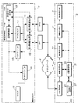
図2は図1の無線映像伝送システム1の詳細構成を示すブロック図であり、図3は無線映像伝送システムにおける映像ストリームの伝送方法の一例を示す模式図であり、図4は映像符号化部13による符号化後のデータの構成例を示す図であり、図5は映像送信部14による送信データの構成例を示す図である。
2 is a block diagram showing a detailed configuration of the wireless
図2に示すように、無線カメラ2において、撮像部11は、図示しない光学レンズ系やCMOS(Complementary Metal Oxide Semiconductor Image Sensor)等からなる固体撮像素子を備え、光学レンズ系から固体撮像素子の撮像面に入射する被写体像を撮像して撮像映像データ(映像信号)を生成する。
As shown in FIG. 2, in the
映像切り出し部12は、図3にも示すように、撮像部11により生成された撮像映像データから注目領域(ROI:Region of Interest)の切り出しを適宜実施する。ユーザは、画像における所定の領域を注目領域として事前に設定しておくことができる。或いは、ユーザは、後述するPC3の映像表示部25において表示された映像を見ながら注目領域を設定してもよい。また、ユーザの操作を介さずに、画像中の人や自動車などの移動物体を周知の画像認識処理等によって自動的に認識し、その移動物体を含む領域を注目領域として設定することも可能である。
As shown in FIG. 3, the
映像符号化部13は、映像切り出し部12から出力された注目領域に関する注目映像データと、撮像部11から出力された撮像映像データ(映像切り出し部12による切り出しが実施された場合には、注目領域外の静止した背景等を含む非注目領域に関する非注目映像データ)を、MPEG2(Moving Picture Experts Group phase 2)等に準拠した周知の圧縮符号化技術を用いて符号化する。ここで、映像符号化部13は、注目領域や非注目領域に含まれる画素ブロック毎に符号量の割り当てを制御することができる。なお、注目領域と非注目領域とは画像領域が互いに異なるが、必ずしも排他的である必要はなく、一部を重複させた構成も可能である。
The
また、映像符号化部13は、後述する送信制御部18により、設定される符号量となるように符号化するが、発生する符号量が多く、設定値を超えるような場合には、撮像部11から出力された撮像映像データを縮小して解像度を下げ、その後に、符号化を実施する。撮像映像データの解像度を下げることで、発生する符号量抑制が可能となり、非注目領域を符号化するための符号量を大幅に削減できる。
In addition, the
ここで、撮像部11から映像符号化部13に入力された撮像映像データ(非注目映像データ)は、例えば、図4(A)に示すように、Iピクチャ(Intra Picture)やPピクチャ(Predictive Picture)等の画像を含むデータ列として映像符号化部13から出力される。また、映像切り出し部12から映像符号化部13に入力された注目映像データは、例えば、図4(B)に示すように、各IピクチャやPピクチャ等の画像毎に注目領域の位置を示す位置情報が付加されたデータ列として映像符号化部13から出力される。
Here, the captured video data (non-focused video data) input from the
映像送信部14は、映像符号化部13において符号化された各映像データをIPパケット化し、個別の映像ストリームとして出力する。つまり、図3にも示すように、映像切り出し部12による切り出しが実施された場合には、注目領域に関する注目映像データは、ハンドオーバの実施時や回線状況の悪化時において伝送品質を確保するために優先されるべき優先映像ストリームとして送信される。一方、非注目領域に関する非注目映像データは、優先する必要のない非優先映像ストリームとして送信される。
The video transmission unit 14 converts each video data encoded by the
ここで、映像符号化部13から映像送信部14に入力された非注目映像データの画像(ここでは、Iピクチャ)は、例えば、図5(A)に示すように、所定の画像サイズをもってRTPヘッダ、UDPヘッダ、IPヘッダが付加されてパケット化される。また、映像符号化部13から映像送信部14に入力された注目映像データの画像(ここでは、Iピクチャ)は、例えば、図5(B)に示すように、位置情報と共にRTPヘッダ、UDPヘッダ、IPヘッダが付加されてパケット化される。なお、Differentiated ServicesなどのQoS保証の仕組みを利用して、優先映像ストリームを優先的に伝送することも可能である。
Here, an image of non-target video data (here, an I picture) input from the
第1無線通信部15は、図示しないアンテナを介してアクセスポイントAP1との間でIEEE 802.11a/b/g等の無線LANの通信規格に準拠した無線通信を行う。映像送信部14にてIPパケット化された各映像データは、第1無線通信部15からアクセスポイントAP1を介してPC3に向けて送信される。ここで、注目映像データと、撮像部11から出力された映像データ(非注目映像データ)とは、個別の映像ストリームとして送信される。なお、第1無線通信部15は、無線通信の回線状況を把握する指標となる受信信号強度を検出することが可能である。
The first
また、第2無線通信部16は、第1無線通信部15と同様の構成および機能を有する。第2無線通信部16は、第1無線通信部15が通信中のアクセスポイント(ここでは、アクセスポイントAP1)とは異なるハンドオーバ先となり得るアクセスポイント(ここでは、アクセスポイントAP2)の存在を予め設定された周期で検出し、このハンドオーバ先候補のアクセスポイントとの間で無線通信を行う。第2無線通信部16は、アクセスポイントの検出時には、受信信号強度を測定しておき、後述するハンドオーバ時に、複数のAP2候補が存在する場合には、受信信号強度の測定結果に基づき、より受信信号強度の大きいAP2を選択するように動作する。
The second
なお、無線カメラ2において、アクセスポイントAP1からアクセスポイントAP2へのハンドオーバが実施された後は、第1無線通信部15と第2無線通信部16とは互いに逆の機能を果たすことになる。
In the
通信制御部17は、第1および第2無線通信部15、16による無線通信の制御を始めとして、無線映像伝送システム1における通信を統括制御する。通信制御部17において、送信制御部18は、映像切り出し部12および映像符号化部13の動作を制御することにより、PC3に対する各映像データの送信を制御する。また、送信モード決定部19は、無線通信の回線状況とハンドオーバの実施状況とに基づき、高品質な映像データの伝送を実現するために無線カメラ2が実行すべき動作モードを予め設定された複数の動作モードの中から決定する。これにより、送信制御部18は、決定された動作モードにしたがって各映像データの送信を制御する。
The communication control unit 17 performs overall control of communication in the wireless
一方、受信側のPC3において、NW(ネットワーク)通信部21は、IPネットワーク4を介してアクセスポイントAP1、AP2に接続されており、TCP/IPプロトコル等の周知のプロトコルに準拠して、無線カメラ2との間で映像ストリームや各種制御情報の送受信を実行する。
On the other hand, in the PC 3 on the receiving side, the NW (network)
映像受信部22は、受信データを蓄積するバッファ機能を有しており、NW通信部21により無線カメラ2から受信したIPパケットに含まれる符号化された映像データを映像復号部23に対して出力する。映像復号部23では映像受信部22からの各映像データが復号される。ここで復号された注目映像データおよびこれに対応する非注目映像データは、図3にも示したように、必要に応じて映像合成部24において合成される。このようにして取得された映像データは、液晶ディスプレイ等を備えた映像表示部25において表示される。
The
なお、後述するハンドオーバの実施時には、映像表示部25において表示される注目領域の位置を固定するとよい。その場合、注目領域の表示位置は、優先映像ストリームの送信時に無線カメラ2側から指定することができる。これにより、ユーザにハンドオーバ中であることを認識させることができると共に、ハンドオーバ中の注目領域の見やすさが向上する。また、この場合、注目領域の位置の固定の要否は、無線カメラ2における受信信号強度の大きさに応じて決定することができ、例えば、受信信号強度が予め設定した閾値よりも小さい場合にのみ注目領域の位置を固定するとよい。これにより、受信信号強度が大きい場合には、ハンドオーバ中であっても注目領域の位置が固定されないため、より自然な映像表示が可能となる。
It should be noted that the position of the region of interest displayed on the
受信制御部26は、映像受信部22、映像復号部23および映像合成部24の動作を制御することにより、PC3に対する各映像データの受信および表示を制御する。また、ストリーム選択部27は、受信制御部26と共同し、映像受信部22によって同種の映像ストリームが複数受信された場合(すなわち、無線カメラ2の第1、第2無線通信部15、16からそれぞれ同種の映像ストリームが送信された場合)、各映像ストリームの受信状況に応じて、映像復号部23にて復号すべき映像ストリームを選択する。
The
なお、PC3は、CPU(Central Processing Unit)やROM(Read Only Memory)、RAM(Random Access Memory)、入出力インタフェース等から構成されており、上記各部の機能の一部または全てを所定のアプリケーションソフトウェアの処理により実現することができる。 The PC 3 includes a CPU (Central Processing Unit), a ROM (Read Only Memory), a RAM (Random Access Memory), an input / output interface, and the like. This process can be realized.
上記構成の無線カメラ2では、通信制御部17が、無線通信の回線状況とハンドオーバの実施状況とに基づき、各映像ストリームについて第1、第2無線通信部15、16からの送信の適否を決定する。この通信制御部17による各映像ストリームの送信の適否の決定は、次の3つの動作モードが選択的に実行されることにより具現化される。
In the
ここで、無線カメラ2の3つの動作モードは、撮像部11から出力された撮像映像データを1つの映像ストリームとして第1無線通信部15からアクセスポイントAP1に対して送信する1ストリームモードと、注目映像データを含む優先映像ストリームおよび非注目映像データを含む非優先映像ストリームを第1無線通信部15からアクセスポイントAP1に対して送信する2ストリームモードA(ハンドオーバなし)と、注目映像データを含む優先映像ストリームおよび非注目映像データを含む非優先映像ストリームを第1無線通信部15からアクセスポイントAP1に対して送信し、且つ、注目映像データを含む優先映像ストリームのみを第2無線通信部16からアクセスポイントAP2に対して送信する2ストリームモードB(ハンドオーバあり)とからなる。
Here, the three operation modes of the
図6は無線カメラ2による映像ストリームの送信動作を示すフロー図であり、図7は無線カメラ2の2ストリームモードA(ハンドオーバなし)における映像ストリーム送信の説明図であり、図8は無線カメラ2の2ストリームモードB(ハンドオーバあり)における映像ストリーム送信の説明図である。
FIG. 6 is a flowchart showing video stream transmission operation by the
無線カメラ2が起動すると、まず、第1無線通信部15は、図1に示したように、現在位置が属するカバーエリア5に対応するアクセスポイントAP1に接続される。一方、現時点で通信を行う必要のない(すなわち、後にハンドオーバ先となるアクセスポイントAP2と通信する)第2無線通信部16では、アクセスポイントAP1の受信信号強度が検出される(ST101)。なお、第1無線通信部15により、AP1の受信信号強度を検出する構成とすることも可能である。
When the
ここで、検出された受信信号強度が予め設定した第1の基準値Xを越えている場合(ST101:Yes)、送信モード決定部19は、無線通信の回線状況が良好であると判断して1ストリームモードを実施する。また、受信信号強度の値が第1の基準値Xよりも小さく(ST101:No)かつ第2の基準値Yよりも大きい場合(ST102:Yes)、送信モード決定部19は、無線通信の回線状況がやや悪化していると判断して2ストリームモードAを実施する。さらに、受信信号強度の値が第2の基準値Y以下である場合(ST102:No)、送信モード決定部19は、ハンドオーバの実施を必要とする程度まで無線通信の回線状況が悪化したと判断して2ストリームモードB(ハンドオーバあり)を実施する。
Here, when the detected received signal strength exceeds the preset first reference value X (ST101: Yes), the transmission
1ストリームモード(ST101:Yes)では、映像切り出し部12による注目領域の切り出し動作が停止される(ST103)。これにより、撮像部11から出力された撮像映像データは、そのまま映像符号化部13において符号化され(ST104)、第1無線通信部15からアクセスポイントAP1を介してPC3に向けて1つの映像ストリームとして送信される(ST105)。
In the 1-stream mode (ST101: Yes), the region of interest clipping operation by the
この1ストリームモードでは、図1に示したように、無線カメラ2の現在位置はカバーエリア5内における比較的電波の届き安い場所(中央付近等)にあるため、従来の伝送方法と同様に、注目領域の切り出し等による符号量の削減を行わない場合でも十分な伝送帯域を確保できる。
In this one-stream mode, as shown in FIG. 1, the current position of the
2ストリームモードA(ST102:Yes)では、映像切り出し部12による注目領域の切り出し動作が開始される(ST106)。これにより、映像符号化部13において、注目映像データおよび非注目映像データがそれぞれ符号化され(ST107)、それぞれ優先映像ストリームおよび非優先映像ストリームとして、第1無線通信部15からアクセスポイントAP1を介してPC3に送信される(ST108)。
In the 2-stream mode A (ST102: Yes), the region-of-interest segmenting operation by the
この2ストリームモードAでは、図7に示すように、無線カメラ2の現在位置はカバーエリア5の内における比較的電波の届き難い場所(境界付近等)にある。しかしながら、PC3では、無線カメラ2から送信された優先映像ストリームおよび非優先映像ストリームの一方または双方を表示等のための映像データとして適宜利用することができるため、回線状況が悪化した場合でも高品質な映像データの伝送を実現できる。
In the 2-stream mode A, as shown in FIG. 7, the current position of the
2ストリームモードB(ST102:No)では、上述のステップST106、ST107とそれぞれ同様のステップST109、ST110が実施される。続いて、送信制御部18は、PC3からハンドオーバの完了通知を受信していない場合(ST111:No)、上述のステップST108と同様のステップST112を実行し、更に、第2無線通信部16からアクセスポイントAP2を介してPC3に向けて優先映像ストリームのみを送信する(ST113)。なお、ユーザによって予め定められた規定時間内にPC3からハンドオーバの完了通知を受信していない場合には、送信制御部18は、無線カメラ2がハンドオーバ可能な位置にない(すなわち、全てのアクセスポイントのカバーエリアから外れた)と判定してユーザに対してエラー表示等をしてもよい。
In 2-stream mode B (ST102: No), steps ST109 and ST110 similar to steps ST106 and ST107 described above are performed. Subsequently, when the handover control notification is not received from the PC 3 (ST111: No), the transmission control unit 18 executes step ST112 similar to the above-described step ST108, and further accesses from the second
一方、送信制御部18は、PC3からハンドオーバの完了通知を受信すると(ST111:Yes)、ステップST112において開始した第1無線通信部15からの優先映像ストリームおよび非優先映像ストリームの送信を停止する(ST114)。続いて、送信制御部18は、優先映像ストリームに加えて非優先映像ストリームを第2無線通信部16からアクセスポイントAP2を介してPC3に送信する(ST115)。
On the other hand, when receiving the handover completion notification from the PC 3 (ST111: Yes), the transmission control unit 18 stops transmission of the priority video stream and the non-priority video stream from the first
この2ストリームモードBでは、図8に示すように、無線カメラ2の現在位置はカバーエリア5とカバーエリア6とが重なる両カバーエリアの境界にある。しかしながら、ハンドオーバ先となり得る第2のアクセスポイントに対して、符号削減された優先映像ストリームが送信されるため、ハンドオーバ実施中でも高品質な映像データの伝送を実現できる。また、PC3は、各映像ストリームの受信状況に応じて注目映像データ(優先映像データ)および非注目映像データ(非優先映像データ)の一方または双方を表示等のための映像データとして適宜利用することができるため、ハンドオーバの完了後の第2のアクセスポイントのカバーエリアの境界付近において回線状況が悪化した場合でも高品質な映像データの伝送を実現できる。
In the 2-stream mode B, as shown in FIG. 8, the current position of the
上記一連のステップは、最終的に通信制御部17において全ての送信動作が完了したと判断される(ST116:Yes)まで、繰り返し実施される。 The series of steps is repeatedly performed until it is finally determined that all transmission operations are completed in the communication control unit 17 (ST116: Yes).
このように、無線カメラ2では、優先映像データおよび非優先映像データを個別の映像ストリームとして送信すると共に、当該各映像ストリームの送信の適否を回線状況やハンドオーバの実施状況に基づき判定するため、優先映像データおよび非優先映像データの符号量を独立して制御することが可能となり、無線通信において制御可能な符号量の範囲を拡大することができる。したがって、ハンドオーバの実施時や、アクセスポイントのカバーエリアの境界付近において回線状況が悪化した場合でも、映像の乱れや画質の低下を抑制して高品質な映像データの伝送を実現できる。
As described above, the
なお、上記ステップST114においては、非優先映像ストリームのみの送信を停止する(すなわち、優先映像ストリームのみを送信する)ことも可能である。この場合、ハンドオーバ元のアクセスポイントAP1に対して送信する優先映像ストリームとしては、ハンドオーバ先とは異なる特定の映像データ(例えば、Iピクチャ)のみを送信することもできる。これにより、ハンドオーバ元のアクセスポイントに対する伝送帯域を節約することが可能となる。また、ハンドオーバ元への映像データの送信を一部継続することにより、再びアクセスポイントAP1へのハンドオーバが実施された場合でも高品質な映像データの伝送を確保できるという利点もある。 In step ST114, transmission of only the non-priority video stream can be stopped (that is, only the priority video stream is transmitted). In this case, only specific video data (for example, I picture) different from the handover destination can be transmitted as the priority video stream transmitted to the handover source access point AP1. This makes it possible to save the transmission band for the handover source access point. Further, by continuing the transmission of the video data to the handover source, there is an advantage that high quality video data transmission can be secured even when the handover to the access point AP1 is performed again.
また、上記ステップ112においては、優先映像ストリームのみを送信することも可能である。この場合、ハンドオーバ元のアクセスポイントAP1に対して送信する映像ストリームとしては、ハンドオーバ先とは異なる特定の映像データ(例えば、Iピクチャ)のみを送信することもできる。これにより、ハンドオーバ元のアクセスポイントに対する伝送帯域を節約することが可能となる。 In step 112, it is also possible to transmit only the priority video stream. In this case, only specific video data (for example, I picture) different from the handover destination can be transmitted as the video stream to be transmitted to the handover source access point AP1. This makes it possible to save the transmission band for the handover source access point.
また、上記ステップST113においては、第2無線通信部16からPC3に向けて優先映像ストリームのみを送信する構成としたが、優先映像ストリームについて必要な伝送帯域を確保できず、且つ非優先映像ストリームの方がより符号量が小さい場合には、非優先映像ストリームのみを送信する構成も可能である。このステップST113に関する変更例の詳細について図9を参照して説明する。
In step ST113, only the priority video stream is transmitted from the second
図9は無線映像伝送システム1におけるアクセスポイントAP1、AP2間の距離と受信信号強度との関係を示す説明図である。ここで、(A)はアクセスポイント間の距離が小さい場合、(B)はアクセスポイント間の距離が大きい場合を示している。
FIG. 9 is an explanatory diagram showing the relationship between the distance between the access points AP1 and AP2 and the received signal strength in the wireless
図9(A)に示すように、アクセスポイントAP1、AP2間の距離が比較的小さく、それらが重なる領域(斜線部分参照)において受信信号強度が比較的大きい(すなわち、確保できる可用帯域が比較的大きい)場合、優先映像ストリームを送信するのに好適である。一方、図9(B)に示すように、アクセスポイントAP1、AP2間の距離が比較的大きく、それらが重なる領域(斜線部分参照)において受信信号強度が比較的小さい(すなわち、確保できる可用帯域が比較的小さい)場合、非優先映像ストリームを送信するのに好適である。このように、優先映像ストリームを伝送できない可用帯域の場合でも、非優先映像ストリームを送信することにより、映像の途切れを軽減できるという利点がある。 As shown in FIG. 9A, the distance between the access points AP1 and AP2 is relatively small, and the received signal strength is relatively large (that is, the available bandwidth that can be secured is relatively large) in the overlapping region (see the shaded area). Large) is suitable for transmitting the priority video stream. On the other hand, as shown in FIG. 9B, the distance between the access points AP1 and AP2 is relatively large, and the received signal strength is relatively small in the overlapping area (see the shaded area) (that is, the available bandwidth that can be secured is small). (Relatively small) is suitable for transmitting non-priority video streams. In this way, even in the case of an available band where the priority video stream cannot be transmitted, there is an advantage that the interruption of the video can be reduced by transmitting the non-priority video stream.
なお、ステップST101、ステップST102において、AP1に関する受信信号強度を用いて、送信モードを決定したが、AP2に関する受信信号強度を用いることも可能である。例えば、AP1の受信強度よりもAP2の受信強度が大きい場合には、2ストリームモードを介すことなく、1ストリームモードで、送信先をAP2に切り替えるという制御が可能である。 In step ST101 and step ST102, the transmission mode is determined using the received signal strength related to AP1, but the received signal strength related to AP2 can also be used. For example, when the reception strength of AP2 is higher than the reception strength of AP1, it is possible to control to switch the transmission destination to AP2 in the 1-stream mode without going through the 2-stream mode.
図10はPC3による映像ストリームの受信動作を示すフロー図である。PC3において映像ストリームの受信が開始されると、ストリーム選択部27は、映像受信部22において1つの映像ストリームのみが受信されているか否かを判定する(ST201)。ここで、無線カメラ2において1ストリームモードが実施されることにより、1つの映像ストリームのみがPC3で受信されている場合(Yes)、その映像ストリームは、映像復号部23にて復号され(ST202)、映像合成部24による合成処理を経ることなく(ST203)、映像表示部25において表示される。
FIG. 10 is a flowchart showing an operation of receiving a video stream by the PC 3. When reception of the video stream is started in the PC 3, the
また、ステップST201において1つの映像ストリームのみが受信されていない場合(No)、ストリーム選択部27は、更に、映像受信部22において2つの映像ストリームが受信されているか否かを判定する(ST204)。ここで、無線カメラ2において2ストリームモードAが実施されることにより、2つの映像ストリームがPC3で受信されている場合(Yes)、それら映像ストリームは、映像復号部23にてそれぞれ復号され(ST205)、復号された注目映像データおよびこれに対応する非注目映像データは、映像合成部24において合成され(ST206)、映像表示部25において表示される。
If only one video stream is not received in step ST201 (No), the
また、ステップST204において2つの映像ストリームのみが受信されていない場合(No)、ストリーム選択部27は、更に、映像受信部22において3つの映像ストリームが受信されているか否かを判定する(ST207)。ここで、無線カメラ2において2ストリームモードBが実施されることにより、3つの映像ストリームがPC3で受信されている場合(Yes)、ストリーム選択部27は、それら映像ストリームに含まれる2つの優先映像ストリーム(同種の映像ストリーム)の一方を、それら優先映像ストリームの受信状況の良否に応じて(例えば、パケットロス率やジッタ変動を指標として)、映像復号部23にて復号すべき映像ストリームとして選択する(ST208)。これにより、受信状況がより良好な映像ストリームに基づき映像を再生することができるため、高品質な映像データの伝送が可能となる。なお、受信状況の良否の指標としては、復号時のシンタクスエラーの頻度を用いてもよい。
If only two video streams are not received in step ST204 (No), the
続いて、ストリーム選択部27は、ステップST208において選択した一方の優先映像ストリームがハンドオーバ先に送られたものであるか否かを判定し(ST209)、ハンドオーバ先に送られたものでない場合には(No)、上述のステップST205、ST206とそれぞれ同様のステップST210、ST211を実行する。一方、優先映像ストリームがハンドオーバ先に送られたものである場合(ST209:Yes)、受信制御部26は、ステップST210、ST211を実行する前に、無線カメラ2に対してハンドオーバが完了した旨を知らせるためのハンドオーバ完了通知を送信する(ST212)。これにより、無線カメラ2においてハンドオーバ完了のタイミングを確実に把握することができるため、高品質な映像データの伝送が可能となる。
Subsequently, the
上記一連のステップは、最終的に受信制御部26において全ての送信動作が完了したと判断される(ST213:Yes)まで、繰り返し実施される。 The series of steps is repeatedly performed until it is determined that all transmission operations are finally completed in the reception control unit 26 (ST213: Yes).
本発明を特定の実施形態に基づいて説明したが、これらの実施形態はあくまでも例示であって、本発明はこれらの実施形態によって限定されるものではない。 Although the present invention has been described based on specific embodiments, these embodiments are merely examples, and the present invention is not limited to these embodiments.
たとえば、本発明に係る無線映像送信装置としては、上述の無線カメラに限らず、少なくとも無線通信機能と映像データの送信機能を有するものであればよい。また、本発明に係る無線映像受信装置としては、上述のPCに限らず、少なくとも無線映像送信装置から映像データを受信し、その受信した映像データを復号する機能を有するものであればよい。 For example, the wireless video transmission device according to the present invention is not limited to the above-described wireless camera, and may be any device that has at least a wireless communication function and a video data transmission function. Further, the wireless video receiving apparatus according to the present invention is not limited to the above-described PC, and any wireless video receiving apparatus may be used as long as it has a function of receiving video data from at least the wireless video transmitting apparatus and decoding the received video data.
また、上記実施形態では、注目領域の切り出しにより互いに画像領域の異なる優先映像データ(注目映像データ)および非優先映像データ(非注目映像データ)を生成する構成としたが、例えば、映像データの符号化にH.264 SVC等のスケーラブルコーデックを用いることにより、互いに画像解像度が異なる優先映像データおよび非優先映像データを生成する構成も可能である。この場合、量子化値を制御することより、優先映像データでは、注目領域を高画質に符号化すると共に、非注目領域を低画質で符号化し、一方、非優先映像データでは、注目領域を低画質に符号化すると共に、非注目領域を高画質で符号化することができる。 In the above embodiment, the priority video data (notice video data) and the non-priority video data (non-note video data) having different image areas are generated by cutting out the attention area. By using a scalable codec such as H.264 SVC for conversion, priority video data and non-priority video data having different image resolutions can be generated. In this case, by controlling the quantization value, in the priority video data, the attention area is encoded with high image quality, and the non- attention area is encoded with low image quality, while in the non-priority video data, the attention area is reduced. In addition to encoding with image quality, it is possible to encode a non-target area with high image quality.
なお、上記実施形態に示した本発明に係る無線映像送信装置および無線映像受信装置ならびにこれらを備えた無線映像伝送システムの各構成要素は、必ずしも全てが必須ではなく、少なくとも本発明の範囲を逸脱しない限りにおいて適宜取捨選択することが可能である。 Note that the components of the wireless video transmission device and the wireless video reception device and the wireless video transmission system including the wireless video transmission device and the wireless video transmission device according to the present invention described in the above embodiments are not necessarily essential, and at least depart from the scope of the present invention. As long as it is not, selection can be made as appropriate.
本発明に係る無線映像送信装置および無線映像受信装置ならびにこれらを備えた無線映像伝送システムは、ハンドオーバの実施時や、アクセスポイントのカバーエリアの境界付近において回線状況が悪化した場合でも、映像の乱れや画質の低下を抑制して高品質な映像データの伝送を実現可能とし、複数のアクセスポイント(基地局)を切り替えながら無線通信によって映像信号を送受信するための無線映像送信装置および無線映像受信装置ならびにこれらを備えた無線映像伝送システムとして有用である。 The wireless video transmission device, the wireless video reception device, and the wireless video transmission system including the same according to the present invention are not distorted even when the line condition deteriorates near the boundary of the access point cover area or at the time of handover. Wireless video transmission device and wireless video reception device capable of transmitting high-quality video data while suppressing deterioration of image quality and transmitting and receiving video signals by wireless communication while switching a plurality of access points (base stations) In addition, it is useful as a wireless video transmission system equipped with these.
1 無線映像伝送システム
2 無線カメラ(無線映像送信装置)
3 PC(無線映像受信装置)
11 撮像部
12 映像切り出し部(データ生成部)
13 映像符号下部
15 第1無線通信部
16 第2無線通信部
17 通信制御部
23 映像受信部(データ受信部)
26 受信制御部(ハンドオーバ完了通知部)
27 ストリーム選択部
AP1 第1のアクセスポイント
AP2 第2のアクセスポイント
1 Wireless
3 PC (wireless video receiver)
11
13 Video code
26 Reception Control Unit (Handover Completion Notification Unit)
27 Stream selector AP1 First access point AP2 Second access point
Claims (11)
前記第1のアクセスポイントのハンドオーバ先候補である第2のアクセスポイントと通信する第2の無線通信部と、
前記第1および第2の無線通信部による無線通信を制御する通信制御部と
を備え、
前記通信制御部は、
前記第1のアクセスポイントとの間の通信の回線状況と、前記第2のアクセスポイントへのハンドオーバの実施状況とに基づき、前記第1および第2の無線通信部からの送信適否を決定し、少なくとも画像領域または画像解像度が互いに異なるデータが符号化された優先映像データと非優先映像データとを個別の2つの映像ストリームとして前記第1および第2の無線通信部から送信し、
前記回線状況が、前記送信適否に関わる第1の基準を満たさない場合、前記2つの映像ストリームの双方を前記第1の無線通信部から前記第1のアクセスポイントに対して送信し、
前記回線状況が、前記第1の基準よりも低い第2の基準を満たさない場合、前記2つの映像ストリームの一方を前記第2の無線通信部から前記第2のアクセスポイントに対して送信することを特徴とする無線映像送信装置。 A first wireless communication unit communicating with the first access point;
A second wireless communication unit that communicates with a second access point that is a handover destination candidate of the first access point;
A communication control unit for controlling wireless communication by the first and second wireless communication units,
The communication control unit
Based on the line status of communication with the first access point and the implementation status of handover to the second access point, determine whether transmission from the first and second radio communication units is appropriate, Transmitting the priority video data and the non-priority video data encoded with at least data having different image areas or image resolutions from the first and second wireless communication units as two separate video streams ,
If the line status does not satisfy the first criterion related to the transmission suitability, both the two video streams are transmitted from the first wireless communication unit to the first access point,
When the line status does not satisfy a second criterion lower than the first criterion, one of the two video streams is transmitted from the second wireless communication unit to the second access point. A wireless video transmission device characterized by the above.
前記第1および第2のアクセスポイントを介して前記無線映像送信装置から送信された前記2つの映像ストリームを受信するデータ受信部と、
受信した少なくとも1つの映像ストリームに含まれる映像データを復号する映像復号部と
を備えたことを特徴とする無線映像受信装置。 A wireless video receiver that communicates with the wireless video transmitter according to claim 1 or 2 ,
A data receiving unit for receiving the two video streams transmitted from the wireless video transmission device via the first and second access points;
A wireless video receiving apparatus comprising: a video decoding unit that decodes video data included in at least one received video stream.
第1のアクセスポイントとの間の通信の回線状況を取得するステップと、
前記第1のアクセスポイントのハンドオーバ先である第2のアクセスポイントへのハンドオーバの実施状況を取得するステップと、
前記回線状況と前記実施状況とに基づいて、少なくとも画像領域または画像解像度が互いに異なるデータが符号化された優先映像データと非優先映像データとを個別の2つの映像ストリームとして前記第1および第2のアクセスポイントへ送信する送信ステップと、
を含み、
前記送信ステップにおいては、
前記回線状況が、送信適否に関わる第1の基準を満たさない場合、前記2つの映像ストリームの双方を前記第1のアクセスポイントに対して送信し、
前記回線状況が、前記第1の基準よりも低い第2の基準を満たさない場合、前記2つの映像ストリームの一方を前記第2のアクセスポイントに対して送信する無線映像送信方法。 A wireless video transmission method executed by a wireless video transmission system,
Obtaining a line status of communication with the first access point;
Obtaining an implementation status of handover to a second access point which is a handover destination of the first access point;
Based on the line status and the implementation status, the first and second priority video data and non-priority video data encoded with at least data having different image areas or image resolutions as two separate video streams. A transmission step of transmitting to the access point of
Only including,
In the transmission step,
If the line status does not satisfy the first criterion related to transmission suitability, both of the two video streams are transmitted to the first access point;
A wireless video transmission method for transmitting one of the two video streams to the second access point when the line status does not satisfy a second criterion lower than the first criterion .
前記第1のアクセスポイントから前記第2のアクセスポイントへのハンドオーバが完了した場合、前記第1のアクセスポイントに対する前記2つの映像ストリームの送信を停止する一方、前記2つの映像ストリームの双方を前記第2のアクセスポイントに対して送信する請求項8に記載の無線映像送信方法。 In the transmission step,
When handover from the first access point to the second access point is completed, transmission of the two video streams to the first access point is stopped, while both of the two video streams are transferred to the first access point. The wireless video transmission method according to claim 8 , wherein transmission is performed to two access points.
前記第1および第2のアクセスポイントを介して前記2つの映像ストリームを受信するステップと、受信した少なくとも1つの映像ストリームに含まれる映像データを復号する復号ステップとを含む無線映像受信方法。 A wireless video reception method for receiving data transmitted by the wireless video transmission method according to claim 8 or 9 , executed by the wireless video transmission system,
A wireless video receiving method comprising: receiving the two video streams via the first and second access points; and a decoding step of decoding video data included in the received at least one video stream.
Priority Applications (5)
| Application Number | Priority Date | Filing Date | Title |
|---|---|---|---|
| JP2011054652A JP5895163B2 (en) | 2011-03-11 | 2011-03-11 | WIRELESS VIDEO TRANSMITTING DEVICE, WIRELESS VIDEO RECEIVING DEVICE, AND WIRELESS VIDEO TRANSMISSION SYSTEM PROVIDED WITH THE SAME |
| PCT/JP2012/001437 WO2012124276A1 (en) | 2011-03-11 | 2012-03-02 | Wireless video transmission device, wireless video reception device, and wireless video transfer system provided with same |
| EP12747877.4A EP2685771B1 (en) | 2011-03-11 | 2012-03-02 | Wireless video transmission device, wireless video transmission system, and wireless video transmission method |
| US13/641,644 US8745673B2 (en) | 2011-03-11 | 2012-03-02 | Wireless video transmission device, wireless video reception device and wireless video communication system using same |
| CN2012800010394A CN102823239A (en) | 2011-03-11 | 2012-03-02 | Wireless video transmission device, wireless video reception device, and wireless video transfer system provided with same |
Applications Claiming Priority (1)
| Application Number | Priority Date | Filing Date | Title |
|---|---|---|---|
| JP2011054652A JP5895163B2 (en) | 2011-03-11 | 2011-03-11 | WIRELESS VIDEO TRANSMITTING DEVICE, WIRELESS VIDEO RECEIVING DEVICE, AND WIRELESS VIDEO TRANSMISSION SYSTEM PROVIDED WITH THE SAME |
Publications (3)
| Publication Number | Publication Date |
|---|---|
| JP2012191519A JP2012191519A (en) | 2012-10-04 |
| JP2012191519A5 JP2012191519A5 (en) | 2014-04-03 |
| JP5895163B2 true JP5895163B2 (en) | 2016-03-30 |
Family
ID=46830369
Family Applications (1)
| Application Number | Title | Priority Date | Filing Date |
|---|---|---|---|
| JP2011054652A Active JP5895163B2 (en) | 2011-03-11 | 2011-03-11 | WIRELESS VIDEO TRANSMITTING DEVICE, WIRELESS VIDEO RECEIVING DEVICE, AND WIRELESS VIDEO TRANSMISSION SYSTEM PROVIDED WITH THE SAME |
Country Status (5)
| Country | Link |
|---|---|
| US (1) | US8745673B2 (en) |
| EP (1) | EP2685771B1 (en) |
| JP (1) | JP5895163B2 (en) |
| CN (1) | CN102823239A (en) |
| WO (1) | WO2012124276A1 (en) |
Families Citing this family (22)
| Publication number | Priority date | Publication date | Assignee | Title |
|---|---|---|---|---|
| US20130283330A1 (en) * | 2012-04-18 | 2013-10-24 | Harris Corporation | Architecture and system for group video distribution |
| WO2014073170A1 (en) * | 2012-11-07 | 2014-05-15 | パナソニック株式会社 | Video transmission terminal, video transmission method, video transmission program, and video transfer system |
| WO2014175919A1 (en) * | 2013-04-26 | 2014-10-30 | Intel IP Corporation | Shared spectrum reassignment in a spectrum sharing context |
| US9907006B2 (en) | 2013-06-03 | 2018-02-27 | Avago Technologies General Ip (Singapore) Pte. Ltd. | Cross radio access technology access with handoff and interference management using communication performance data |
| US9888422B2 (en) | 2013-06-03 | 2018-02-06 | Avago Technologies General Ip (Singapore) Pte. Ltd. | System and method for adaptive access and handover configuration based on prior history in a multi-RAT environment |
| TWI504292B (en) * | 2013-06-19 | 2015-10-11 | D Link Corp | Network camera with network repeater function and its setting method |
| WO2015019546A1 (en) * | 2013-08-09 | 2015-02-12 | パナソニックIpマネジメント株式会社 | Wireless camera system, central device, image display method, and image display program |
| CN103442202B (en) * | 2013-08-22 | 2017-09-26 | 北京智谷睿拓技术服务有限公司 | Video communication method and device |
| JP5850012B2 (en) * | 2013-08-30 | 2016-02-03 | ブラザー工業株式会社 | Information processing apparatus, program, and communication system |
| JP2015095733A (en) * | 2013-11-11 | 2015-05-18 | キヤノン株式会社 | Image transfer device, image transfer method, and program |
| CN103716808B (en) * | 2013-12-20 | 2016-09-28 | 合肥工业大学 | A kind of wireless sensor network link quality prediction method |
| TWI526080B (en) * | 2013-12-26 | 2016-03-11 | 廣達電腦股份有限公司 | Video conferencing system |
| DE102014205485A1 (en) * | 2014-03-25 | 2015-10-01 | Siemens Aktiengesellschaft | Method for transmitting digital images from a sequence of images |
| EP2934045A1 (en) * | 2014-04-14 | 2015-10-21 | Broadcom Corporation | Systems and methods for splitting and recombining communications in multi-network environments |
| CN105323649A (en) * | 2014-07-18 | 2016-02-10 | 季春宏 | Wireless video transmission method and system of multi-route simultaneous transmission hot standby |
| US10166917B2 (en) | 2014-08-30 | 2019-01-01 | Mariana Goldhamer | Transmission of uncompressed video in cellular networks |
| US9883141B1 (en) | 2016-12-12 | 2018-01-30 | International Business Machines Corporation | Dynamic video image management |
| EP3673672B1 (en) * | 2017-08-25 | 2021-12-01 | Sony Group Corporation | Methods and devices for communication based on image recognition in a wireless communication system |
| CN110856019B (en) * | 2019-11-20 | 2021-11-12 | 广州酷狗计算机科技有限公司 | Code rate allocation method, device, terminal and storage medium |
| WO2021200212A1 (en) * | 2020-03-30 | 2021-10-07 | ソニーグループ株式会社 | Information processing device, information processing method, and program |
| WO2021200226A1 (en) * | 2020-03-30 | 2021-10-07 | ソニーグループ株式会社 | Information processing device, information processing method, and program |
| JP2022155381A (en) * | 2021-03-30 | 2022-10-13 | パナソニックホールディングス株式会社 | connection system |
Family Cites Families (19)
| Publication number | Priority date | Publication date | Assignee | Title |
|---|---|---|---|---|
| US5481312A (en) * | 1994-09-12 | 1996-01-02 | At&T Corp. | Method of and apparatus for the transmission of high and low priority segments of a video bitstream over packet networks |
| US5784695A (en) * | 1996-05-14 | 1998-07-21 | Trw Inc. | Method and apparatus for handover control in a satellite based telecommunications system |
| JP2999461B1 (en) | 1998-09-24 | 2000-01-17 | 東京通信ネットワーク株式会社 | Mobile communication device |
| US7773670B1 (en) * | 2001-06-05 | 2010-08-10 | At+T Intellectual Property Ii, L.P. | Method of content adaptive video encoding |
| US7958532B2 (en) * | 2001-06-18 | 2011-06-07 | At&T Intellectual Property Ii, L.P. | Method of transmitting layered video-coded information |
| US7200402B2 (en) * | 2001-07-03 | 2007-04-03 | Hewlett-Packard Development Company, L.P. | Method for handing off streaming media sessions between wireless base stations in a mobile streaming media system |
| US20040264563A1 (en) * | 2001-11-05 | 2004-12-30 | Akino Inoue | Terminal used in video transmission system |
| JP2003152626A (en) * | 2001-11-14 | 2003-05-23 | Nippon Telegr & Teleph Corp <Ntt> | Terminal device for receiving multicasted stream contents |
| JP2003309594A (en) * | 2002-04-16 | 2003-10-31 | Hitachi Ltd | Video information transmission system |
| US20050213538A1 (en) | 2002-05-31 | 2005-09-29 | Matsushita Electric Industrial Co., Ltd | Data distribution device and transmission method |
| JP2004128579A (en) * | 2002-09-30 | 2004-04-22 | Matsushita Electric Ind Co Ltd | Wireless transmission system and communication terminal |
| JP4312155B2 (en) * | 2002-12-19 | 2009-08-12 | 富士通株式会社 | Mobile node |
| JP4151963B2 (en) | 2003-09-19 | 2008-09-17 | 株式会社リコー | Image server device, client device, moving image distribution method, program, and information recording medium |
| US8553611B2 (en) * | 2004-01-30 | 2013-10-08 | Hewlett-Packard Development Company, L.P. | Systems and methods for multi-access point transmission of data using a plurality of access points |
| EP1826949A1 (en) * | 2006-02-28 | 2007-08-29 | Thomson Licensing | Seamless handover method and system |
| KR100799669B1 (en) * | 2006-06-20 | 2008-01-30 | 삼성전자주식회사 | Information communication method and device for improving the transmitting and receiving efficiency of video signals |
| JP4533347B2 (en) * | 2006-06-26 | 2010-09-01 | 京セラコミュニケーションシステム株式会社 | COMMUNICATION SYSTEM, COMMUNICATION PROGRAM, RECORDING MEDIUM, AND COMMUNICATION METHOD |
| CN101252687B (en) * | 2008-03-20 | 2010-06-02 | 上海交通大学 | Method for implementing multichannel combined interested area video coding and transmission |
| CN104684032B (en) * | 2009-03-12 | 2020-10-30 | 交互数字专利控股公司 | Method and apparatus for performing component carrier specific reconfiguration |
-
2011
- 2011-03-11 JP JP2011054652A patent/JP5895163B2/en active Active
-
2012
- 2012-03-02 US US13/641,644 patent/US8745673B2/en not_active Expired - Fee Related
- 2012-03-02 CN CN2012800010394A patent/CN102823239A/en active Pending
- 2012-03-02 WO PCT/JP2012/001437 patent/WO2012124276A1/en active Application Filing
- 2012-03-02 EP EP12747877.4A patent/EP2685771B1/en not_active Not-in-force
Also Published As
| Publication number | Publication date |
|---|---|
| US20130042279A1 (en) | 2013-02-14 |
| US8745673B2 (en) | 2014-06-03 |
| CN102823239A (en) | 2012-12-12 |
| WO2012124276A1 (en) | 2012-09-20 |
| EP2685771A1 (en) | 2014-01-15 |
| JP2012191519A (en) | 2012-10-04 |
| EP2685771A4 (en) | 2014-08-27 |
| EP2685771B1 (en) | 2017-09-20 |
Similar Documents
| Publication | Publication Date | Title |
|---|---|---|
| JP5895163B2 (en) | WIRELESS VIDEO TRANSMITTING DEVICE, WIRELESS VIDEO RECEIVING DEVICE, AND WIRELESS VIDEO TRANSMISSION SYSTEM PROVIDED WITH THE SAME | |
| JP5914871B2 (en) | Communication terminal and coding rate reduction method | |
| KR101754999B1 (en) | Method and apparatus of motion vector prediction for scalable video coding | |
| JP4787720B2 (en) | Wireless base station, wireless communication system, communication control method, and communication control program | |
| KR20100118146A (en) | Wireless communication device and communication device | |
| US8891539B2 (en) | Re-searching reference image for motion vector and converting resolution using image generated by applying motion vector to reference image | |
| JP5011572B2 (en) | Wireless mobile terminal and connection destination switching method | |
| JP2007252005A (en) | Wireless communication terminal, and communication method | |
| US20150288988A1 (en) | Video transmission terminal, video transmission method, video transmission program, and video transfer system | |
| Menkovski et al. | QoE for mobile streaming | |
| KR100755219B1 (en) | Image data communication system and image data communication method | |
| JP5516409B2 (en) | Gateway device, method, system, and terminal | |
| KR101102514B1 (en) | Method for transmitting high definition moving picture based in media independent handover | |
| JP2010183632A (en) | Mobile communication system, base station, and handover control method | |
| JPH10126856A (en) | Portable video telephone system | |
| KR20110026095A (en) | Apparatus for transmitting real time sd/hd moving picture using wireless multiple access | |
| Abe et al. | Multi-hop 802.11 ad wireless H. 264 video streaming | |
| TWI809939B (en) | Communication apparatus and methods for multimedia adaptation | |
| JP2007174035A (en) | Moving picture communication apparatus and moving picture communication method | |
| KR101364238B1 (en) | Video transmission and reception system, and method thereof operating in accordance with channel status | |
| KR101255511B1 (en) | High definition camera system based in Media Independent Handover | |
| JP5138573B2 (en) | Radio base station and radio communication method | |
| JP2012134860A (en) | Radio transmission terminal and radio transmission method, encoder and encoding method used in the same, and computer program | |
| Ciubotaru Petrescu | Quality-Oriented Mobility Management for Multimedia Content Delivery to Mobile Users | |
| JP2008010986A (en) | Wireless video monitor and method therefor |
Legal Events
| Date | Code | Title | Description |
|---|---|---|---|
| A521 | Request for written amendment filed |
Free format text: JAPANESE INTERMEDIATE CODE: A523 Effective date: 20140214 |
|
| A621 | Written request for application examination |
Free format text: JAPANESE INTERMEDIATE CODE: A621 Effective date: 20140214 |
|
| A711 | Notification of change in applicant |
Free format text: JAPANESE INTERMEDIATE CODE: A711 Effective date: 20141009 |
|
| RD02 | Notification of acceptance of power of attorney |
Free format text: JAPANESE INTERMEDIATE CODE: A7422 Effective date: 20141014 |
|
| A131 | Notification of reasons for refusal |
Free format text: JAPANESE INTERMEDIATE CODE: A131 Effective date: 20150707 |
|
| A521 | Request for written amendment filed |
Free format text: JAPANESE INTERMEDIATE CODE: A523 Effective date: 20150828 |
|
| TRDD | Decision of grant or rejection written | ||
| A01 | Written decision to grant a patent or to grant a registration (utility model) |
Free format text: JAPANESE INTERMEDIATE CODE: A01 Effective date: 20151104 |
|
| A61 | First payment of annual fees (during grant procedure) |
Free format text: JAPANESE INTERMEDIATE CODE: A61 Effective date: 20151119 |
|
| R151 | Written notification of patent or utility model registration |
Ref document number: 5895163 Country of ref document: JP Free format text: JAPANESE INTERMEDIATE CODE: R151 |