JP5891125B2 - Video processing apparatus, video processing method, and video processing system - Google Patents
Video processing apparatus, video processing method, and video processing system Download PDFInfo
- Publication number
- JP5891125B2 JP5891125B2 JP2012147344A JP2012147344A JP5891125B2 JP 5891125 B2 JP5891125 B2 JP 5891125B2 JP 2012147344 A JP2012147344 A JP 2012147344A JP 2012147344 A JP2012147344 A JP 2012147344A JP 5891125 B2 JP5891125 B2 JP 5891125B2
- Authority
- JP
- Japan
- Prior art keywords
- image
- marker
- proximity
- interaction
- virtual
- Prior art date
- Legal status (The legal status is an assumption and is not a legal conclusion. Google has not performed a legal analysis and makes no representation as to the accuracy of the status listed.)
- Active
Links
- 238000012545 processing Methods 0.000 title claims description 27
- 238000003672 processing method Methods 0.000 title claims description 4
- 239000003550 marker Substances 0.000 claims description 109
- 230000003993 interaction Effects 0.000 claims description 62
- 230000000694 effects Effects 0.000 claims description 19
- 238000003384 imaging method Methods 0.000 claims description 15
- 230000003287 optical effect Effects 0.000 claims description 13
- 230000008859 change Effects 0.000 claims description 11
- 230000005540 biological transmission Effects 0.000 claims description 9
- 238000009877 rendering Methods 0.000 claims description 8
- 230000001133 acceleration Effects 0.000 claims description 7
- 230000000007 visual effect Effects 0.000 claims description 7
- 230000003190 augmentative effect Effects 0.000 claims description 4
- 238000004519 manufacturing process Methods 0.000 claims description 2
- 230000000704 physical effect Effects 0.000 claims 1
- 238000005259 measurement Methods 0.000 description 21
- 208000013057 hereditary mucoepithelial dysplasia Diseases 0.000 description 17
- 239000013598 vector Substances 0.000 description 15
- 238000010586 diagram Methods 0.000 description 10
- 230000010365 information processing Effects 0.000 description 10
- 238000000034 method Methods 0.000 description 9
- 230000004048 modification Effects 0.000 description 6
- 238000012986 modification Methods 0.000 description 6
- 239000004973 liquid crystal related substance Substances 0.000 description 4
- 230000009466 transformation Effects 0.000 description 4
- 230000005484 gravity Effects 0.000 description 3
- 238000004364 calculation method Methods 0.000 description 2
- 238000004891 communication Methods 0.000 description 2
- 239000000470 constituent Substances 0.000 description 2
- 238000005516 engineering process Methods 0.000 description 2
- 210000003128 head Anatomy 0.000 description 2
- 230000002452 interceptive effect Effects 0.000 description 2
- 230000008569 process Effects 0.000 description 2
- 239000004065 semiconductor Substances 0.000 description 2
- 241000282412 Homo Species 0.000 description 1
- 241001465754 Metazoa Species 0.000 description 1
- 238000013459 approach Methods 0.000 description 1
- 230000008901 benefit Effects 0.000 description 1
- 210000004556 brain Anatomy 0.000 description 1
- 238000002485 combustion reaction Methods 0.000 description 1
- 230000000295 complement effect Effects 0.000 description 1
- 238000004590 computer program Methods 0.000 description 1
- 238000011161 development Methods 0.000 description 1
- 238000004134 energy conservation Methods 0.000 description 1
- 238000004880 explosion Methods 0.000 description 1
- 210000004709 eyebrow Anatomy 0.000 description 1
- 239000012634 fragment Substances 0.000 description 1
- WABPQHHGFIMREM-UHFFFAOYSA-N lead(0) Chemical compound [Pb] WABPQHHGFIMREM-UHFFFAOYSA-N 0.000 description 1
- 239000011159 matrix material Substances 0.000 description 1
- 229910044991 metal oxide Inorganic materials 0.000 description 1
- 150000004706 metal oxides Chemical class 0.000 description 1
- 230000009467 reduction Effects 0.000 description 1
- 230000008054 signal transmission Effects 0.000 description 1
- 239000000126 substance Substances 0.000 description 1
- 238000002834 transmittance Methods 0.000 description 1
Images


Classifications
-
- G—PHYSICS
- G06—COMPUTING; CALCULATING OR COUNTING
- G06T—IMAGE DATA PROCESSING OR GENERATION, IN GENERAL
- G06T19/00—Manipulating 3D models or images for computer graphics
- G06T19/006—Mixed reality
-
- A—HUMAN NECESSITIES
- A63—SPORTS; GAMES; AMUSEMENTS
- A63F—CARD, BOARD, OR ROULETTE GAMES; INDOOR GAMES USING SMALL MOVING PLAYING BODIES; VIDEO GAMES; GAMES NOT OTHERWISE PROVIDED FOR
- A63F13/00—Video games, i.e. games using an electronically generated display having two or more dimensions
- A63F13/20—Input arrangements for video game devices
- A63F13/21—Input arrangements for video game devices characterised by their sensors, purposes or types
- A63F13/213—Input arrangements for video game devices characterised by their sensors, purposes or types comprising photodetecting means, e.g. cameras, photodiodes or infrared cells
-
- G—PHYSICS
- G02—OPTICS
- G02B—OPTICAL ELEMENTS, SYSTEMS OR APPARATUS
- G02B27/00—Optical systems or apparatus not provided for by any of the groups G02B1/00 - G02B26/00, G02B30/00
- G02B27/01—Head-up displays
- G02B27/017—Head mounted
-
- G—PHYSICS
- G06—COMPUTING; CALCULATING OR COUNTING
- G06F—ELECTRIC DIGITAL DATA PROCESSING
- G06F3/00—Input arrangements for transferring data to be processed into a form capable of being handled by the computer; Output arrangements for transferring data from processing unit to output unit, e.g. interface arrangements
- G06F3/01—Input arrangements or combined input and output arrangements for interaction between user and computer
- G06F3/011—Arrangements for interaction with the human body, e.g. for user immersion in virtual reality
-
- G—PHYSICS
- G06—COMPUTING; CALCULATING OR COUNTING
- G06F—ELECTRIC DIGITAL DATA PROCESSING
- G06F3/00—Input arrangements for transferring data to be processed into a form capable of being handled by the computer; Output arrangements for transferring data from processing unit to output unit, e.g. interface arrangements
- G06F3/01—Input arrangements or combined input and output arrangements for interaction between user and computer
- G06F3/03—Arrangements for converting the position or the displacement of a member into a coded form
- G06F3/0304—Detection arrangements using opto-electronic means
-
- G—PHYSICS
- G09—EDUCATION; CRYPTOGRAPHY; DISPLAY; ADVERTISING; SEALS
- G09G—ARRANGEMENTS OR CIRCUITS FOR CONTROL OF INDICATING DEVICES USING STATIC MEANS TO PRESENT VARIABLE INFORMATION
- G09G5/00—Control arrangements or circuits for visual indicators common to cathode-ray tube indicators and other visual indicators
- G09G5/36—Control arrangements or circuits for visual indicators common to cathode-ray tube indicators and other visual indicators characterised by the display of a graphic pattern, e.g. using an all-points-addressable [APA] memory
-
- G—PHYSICS
- G02—OPTICS
- G02B—OPTICAL ELEMENTS, SYSTEMS OR APPARATUS
- G02B27/00—Optical systems or apparatus not provided for by any of the groups G02B1/00 - G02B26/00, G02B30/00
- G02B27/01—Head-up displays
- G02B27/017—Head mounted
- G02B2027/0178—Eyeglass type
-
- H—ELECTRICITY
- H04—ELECTRIC COMMUNICATION TECHNIQUE
- H04N—PICTORIAL COMMUNICATION, e.g. TELEVISION
- H04N5/00—Details of television systems
- H04N5/74—Projection arrangements for image reproduction, e.g. using eidophor
- H04N5/7475—Constructional details of television projection apparatus
- H04N5/7491—Constructional details of television projection apparatus of head mounted projectors
Landscapes
- Engineering & Computer Science (AREA)
- Theoretical Computer Science (AREA)
- General Engineering & Computer Science (AREA)
- Physics & Mathematics (AREA)
- General Physics & Mathematics (AREA)
- Human Computer Interaction (AREA)
- Multimedia (AREA)
- Computer Hardware Design (AREA)
- Software Systems (AREA)
- Computer Graphics (AREA)
- Optics & Photonics (AREA)
- Processing Or Creating Images (AREA)
- Testing, Inspecting, Measuring Of Stereoscopic Televisions And Televisions (AREA)
- Controls And Circuits For Display Device (AREA)
- User Interface Of Digital Computer (AREA)
Description
本発明は、映像処理装置、映像処理方法、および映像処理システムに関する。 The present invention relates to a video processing device, a video processing method, and a video processing system.
近年、立体映像を提示するための技術開発が進み、奥行きを持った立体映像を提示することが可能なヘッドマウントディスプレイ(Head Mounted Display; 以下「HMD」と記載する。)が普及してきている。このようなHMDの中には、ホログラフィック素子やハーフミラー等を用いて、立体映像をユーザに提示しつつ、かつユーザがHMDの外の様子をシースルーで見ることができる光学透過型HMDも開発されている。 2. Description of the Related Art In recent years, technological development for presenting stereoscopic images has progressed, and a head mounted display (hereinafter referred to as “HMD”) capable of presenting stereoscopic images with depth has become widespread. Among these HMDs, we have also developed an optically transmissive HMD that uses a holographic element, a half mirror, etc. to present stereoscopic images to the user and allows the user to see the outside of the HMD in a see-through manner. Has been.
一方、カメラ等の撮像素子で撮像した実世界の映像にCG(Computer Graphics)等の映像を付加した映像を生成し、ユーザに提示する実世界の映像の一部に修正を加えるAR(Augmented Reality)技術も実用段階に入りつつある。AR技術では、バーコード等の識別可能な特定の情報を認識し、その情報に紐付けて画像を生成する場合もある。 On the other hand, an AR (Augmented Reality) that generates a video in which a video such as CG (Computer Graphics) is added to a real-world video captured by an imaging device such as a camera, and modifies a part of the real-world video presented to the user. ) Technology is also entering the practical stage. In the AR technology, there is a case where specific information such as a barcode is recognized and an image is generated in association with the information.
特定の対象物に紐付けて画像を生成する場合、対象物の位置や向きが変化すると、対象物に紐付けられた画像はその変化に応じて生成される。この結果、互いに異なる対象物に紐付けて生成されたふたつの異なる画像が接近したり、場合によっては接触したりすることも起こり得るが、それを起因として互いの画像に生じる変化を表現することにより、インタラクティブな立体映像を提供できる可能性について本願の発明者は認識するに至った。 When an image is generated in association with a specific object, when the position or orientation of the object changes, the image associated with the object is generated according to the change. As a result, two different images generated by linking to different objects may come close to each other, or in some cases may come into contact with each other. Thus, the inventors of the present application have recognized the possibility of providing interactive stereoscopic images.
本発明はこうした課題に鑑みてなされたものであり、その目的は、特定の対象物に紐付けて生成される画像間の相互作用を演出する技術を提供することにある。 This invention is made | formed in view of such a subject, The objective is to provide the technique which produces the interaction between the images produced | generated linked | related with a specific target object.
上記課題を解決するために、本発明のある態様は映像処理装置である。この装置は、仮想的な3次元空間における3次元イメージを実空間中に投影した場合に観察される映像を提示する光学透過型HMDに備えられた、当該光学透過型HMDを装着するユーザの視野を含む領域にある被写体を撮像する撮像素子が撮像した被写体をマーカとして、前記光学透過型HMDに提示させるARイメージを生成するARイメージ生成部と、第1のマーカに紐付けられた第1ARイメージと、第2のマーカまたは第2のマーカに紐付けられた第2ARイメージとの間の、仮想的な3次元空間における近接度を取得する近接度取得部と、前記近接度取得部が取得した近接度をもとに、第1ARイメージまたは第2ARイメージとの間に生じる相互作用を算出する相互作用演出部とを含む。ここで前記ARイメージ生成部は、前記相互作用演出部が算出した相互作用に応じて、第1ARイメージまたは第2ARイメージの少なくともいずれか一方のイメージを変化させる。 In order to solve the above problems, an aspect of the present invention is a video processing apparatus. This apparatus includes a field of view of a user wearing an optically transmissive HMD provided in an optically transmissive HMD that presents an image observed when a three-dimensional image in a virtual three-dimensional space is projected into a real space. An AR image generation unit that generates an AR image to be presented to the optically transmissive HMD using a subject imaged by an imaging element that captures a subject in an area including the image as a marker, and a first AR image associated with the first marker And the proximity acquisition unit that acquires the proximity in the virtual three-dimensional space between the second marker or the second AR image linked to the second marker and the proximity acquisition unit An interaction rendering unit that calculates an interaction between the first AR image and the second AR image based on the proximity. Here, the AR image generation unit changes at least one of the first AR image and the second AR image according to the interaction calculated by the interaction rendering unit.
本発明の別の態様は、映像処理方法である。この方法は、仮想的な3次元空間における3次元イメージを実空間中に投影した場合に観察される映像を提示する光学透過型HMDと、当該光学透過型HMDを装着するユーザの視野を含む領域にある被写体を撮像する撮像素子とを備える立体映像観察デバイスに提示させる、前記撮像素子が撮像した被写体をマーカとするARイメージを生成するステップと、第1のマーカに紐付けられた第1ARイメージと、第2のマーカまたは第2のマーカに紐付けられた第2ARイメージとの間の、仮想的な3次元空間における近接度を取得するステップと、取得した近接度をもとに、第1ARイメージまたは第2ARイメージとの間に生じる相互作用を算出するステップと、算出した相互作用に応じて、第1ARイメージまたは第2ARイメージの少なくともいずれか一方のイメージを変化させるステップとをプロセッサに実行させる。 Another aspect of the present invention is a video processing method. This method includes an optically transmissive HMD that presents an image observed when a three-dimensional image in a virtual three-dimensional space is projected into a real space, and a region that includes a visual field of a user wearing the optically transmissive HMD. A step of generating an AR image using the subject imaged by the image sensor as a marker, and a first AR image associated with the first marker. And acquiring a proximity in a virtual three-dimensional space between the second marker or the second AR image linked to the second marker and the first AR based on the acquired proximity Calculating an interaction between the image or the second AR image, and depending on the calculated interaction, the first AR image or the second AR image Even without executing a step of changing either one of the image processor.
本発明のさらに別の態様は、映像処理システムである。このシステムは、仮想的な3次元空間における3次元イメージを実空間中に投影した場合に観察される映像を提示する光学透過型HMDと、前記光学透過型HMDに備えられ、前記光学透過型HMDを装着するユーザの視野を含む領域にある被写体を撮像する撮像素子と、前記撮像素子が撮像した被写体をマーカとして、前記光学透過型HMDに提示させるAR(Augmented Reality)イメージを生成するARイメージ生成部と、第1のマーカに紐付けられた第1ARイメージと、第2のマーカまたは第2のマーカに紐付けられた第2ARイメージとの間の、仮想的な3次元空間における近接度を取得する近接度取得部と、前記近接度取得部が取得した近接度をもとに、第1ARイメージまたは第2ARイメージとの間に生じる相互作用を算出する相互作用演出部とを含む。ここで前記ARイメージ生成部は、前記相互作用演出部が算出した相互作用に応じて、第1ARイメージまたは第2ARイメージの少なくともいずれか一方のイメージを変化させる。 Yet another embodiment of the present invention is a video processing system. The system includes an optically transmissive HMD that presents an image observed when a three-dimensional image in a virtual three-dimensional space is projected into a real space, and the optically transmissive HMD. An image pickup device that picks up an image of a subject in a region including the field of view of the user wearing the image, and an AR image generation that generates an AR (Augmented Reality) image to be presented to the optically transmissive HMD using the subject imaged by the image pickup device as a marker The degree of proximity in a virtual three-dimensional space between the first AR image linked to the first marker and the second AR image linked to the second marker or the second marker Based on the proximity acquired by the proximity acquisition unit and the proximity acquisition unit, the interaction between the first AR image or the second AR image is calculated. And an interaction for the directing department. Here, the AR image generation unit changes at least one of the first AR image and the second AR image according to the interaction calculated by the interaction rendering unit.
本発明のさらに別の態様は、上記の方法の各ステップをコンピュータに実現させるプログラムである。 Yet another embodiment of the present invention is a program that causes a computer to implement the steps of the above method.
このプログラムは、ビデオやオーディオのデコーダ等のハードウェア資源の基本的な制御を行なうために機器に組み込まれるファームウェアの一部として提供されてもよい。このファームウェアは、たとえば、機器内のROM(Read Only Memory)やフラッシュメモリなどの半導体メモリに格納される。このファームウェアを提供するため、あるいはファームウェアの一部をアップデートするために、このプログラムを記録したコンピュータ読み取り可能な記録媒体が提供されてもよく、また、このプログラムが通信回線で伝送されてもよい。 This program may be provided as part of firmware incorporated in the device in order to perform basic control of hardware resources such as video and audio decoders. This firmware is stored in a semiconductor memory such as a ROM (Read Only Memory) or a flash memory in the device, for example. In order to provide the firmware or to update a part of the firmware, a computer-readable recording medium storing the program may be provided, and the program may be transmitted through a communication line.
なお、以上の構成要素の任意の組合せ、本発明の表現を方法、装置、システム、コンピュータプログラム、データ構造、記録媒体などの間で変換したものもまた、本発明の態様として有効である。 It should be noted that any combination of the above-described constituent elements and the expression of the present invention converted between a method, an apparatus, a system, a computer program, a data structure, a recording medium, and the like are also effective as an aspect of the present invention.
本発明によれば、特定の対象物に紐付けて生成される画像間の相互作用を演出する技術を提供することができる。 ADVANTAGE OF THE INVENTION According to this invention, the technique which produces the interaction between the images produced | generated linked | related with a specific target object can be provided.
本発明の実施の形態の概要を述べる。本発明の実施の形態は、ユーザの操作によって移動された3次元イメージが別の3次元イメージに近づいたとき、その近接度をもとに、3次元イメージ間の仮想的な相互作用を演出し、3次元イメージに反映させる。また、相互作用とは例えば3次元イメージ間の接触や衝突等であり、相互作用の前後における3次元イメージの仮想的な速度や加速度等の属性に応じて、3次元イメージを変化させて提示する。 An outline of an embodiment of the present invention will be described. The embodiment of the present invention produces a virtual interaction between 3D images based on the proximity when a 3D image moved by a user operation approaches another 3D image. Reflect in the 3D image. Further, the interaction is, for example, contact or collision between the three-dimensional images, and the three-dimensional image is changed and presented according to attributes such as virtual speed and acceleration of the three-dimensional image before and after the interaction. .
図1は、実施の形態に係る映像提示システム100の全体構成を模式的に示す図である。実施の形態に係る映像提示システム100は、立体映像観察デバイス200、3次元モニタ300、および情報処理装置400を含む。
FIG. 1 is a diagram schematically illustrating an overall configuration of a
立体映像観察デバイス200は、光学透過型HMDである。ここで立体映像観察デバイス200は、後述する3次元モニタ300を観察するための光学シャッタ(図示せず)を備えてもよい。光学シャッタは3次元モニタ300の視差画像の切替と同期して、左右のシャッタを開閉する。より具体的には、3次元モニタ300が左目用の視差画像を表示しているときは、右目用のシャッタを閉じるとともに左目用のシャッタを開け、立体映像観察デバイス200を装着するユーザに左目用の視差画像を提示する。反対に、3次元モニタ300が右目用の視差画像を表示しているときは、左目用のシャッタを閉じるとともに右目用のシャッタを開け、ユーザに右目用の視差画像を提示する。光学シャッタは、例えば既知の液晶シャッタを用いて実現できる。
The stereoscopic
立体映像観察デバイス200は、シャッタ切替のための同期信号を受信する。同期信号は、3次元モニタ300または情報処理装置400に設けられた図示しない信号送信部から、例えば赤外光等を用いて無線で伝達される。
The stereoscopic
3次元モニタ300は、フレームシーケンシャル方式で立体映像を表示する。人間の左右の目は6cm程度離れているため、左目から見える映像と右目から見える映像には視差が生じる。人間の脳は、左右の目で知覚した視差画像を、奥行きを認識するためのひとつの情報として利用しているといわれている。そのため、左目で知覚される視差画像と右目で知覚される視差画像とをそれぞれの目に投影すると、人間には奥行きを持った映像として認識される。3次元モニタ300は、左目用の視差画像と右目用の視差画像とを交互に時分割で表示する。3次元モニタ300は、液晶テレビやプラズマディスプレイ、有機ELモニタ等の既知の提示デバイスを用いて実現できる。
The three-
情報処理装置400は、映像提示システム100で提示するための立体映像や上述した同期信号を取得する。情報処理装置400の例としては、例えば据置型のゲーム機や携帯ゲーム機等である。情報処理装置400は内蔵するプロセッサを用いて立体映像や同期信号を生成したり、図示しないネットワークインタフェースを介して、サーバ等の他の情報処理装置から立体映像を取得したりする。
The
図2は、実施の形態に係る立体映像観察デバイス200の外観の一例を模式的に示す図である。立体映像観察デバイス200は、立体映像を提示する提示部202、撮像素子204、および種々のモジュールを収納する筐体206を含む。
FIG. 2 is a diagram schematically illustrating an example of the appearance of the stereoscopic
提示部202は、ユーザの目に立体映像を提示する光学透過型HMDと、光学透過型HMDを透過する外界の光の透過率を変更する液晶シャッタとを含む。撮像素子204は、立体映像観察デバイス200を装着するユーザの視野を含む領域にある被写体を撮像する。このため、撮像素子204は、立体映像観察デバイス200をユーザが装着したとき、ユーザの眉間のあたりに配置されるように設置されている。撮像素子204は、例えばCCD(Charge Coupled Device)イメージセンサやCMOS(Complementary Metal Oxide Semiconductor)イメージセンサ等の既知の固体撮像素子を用いて実現できる。
The
筐体206は、めがね形状の立体映像観察デバイス200におけるフレームの役割を果たすとともに、立体映像観察デバイス200が利用する様々なモジュール(図示せず)を収納する。立体映像観察デバイス200が利用するモジュールとは、光学透過型HMDを実現するためのホログラム導光板を含む光学エンジン、液晶シャッタを駆動するためのドライバや同期信号受信部、その他Wi−Fi(登録商標)モジュール等の通信モジュール、電子コンパス、加速度センサ、傾きセンサ、GPS(Global Positioning System)センサ、および照度センサ等である。これらのモジュールは例示であり、また立体映像観察デバイス200はこれらのモジュールを必ずしも全て搭載する必要はない。いずれのモジュールを搭載するかは、立体映像観察デバイス200が想定する利用シーンに応じて決定すればよい。
The
図2は、めがね型の立体映像観察デバイス200を例示する図である。立体映像観察デバイス200の形状は、この他にも帽子形状、ユーザの頭部を一周して固定されるベルト形状、ユーザの頭部全体を覆うヘルメット形状等さまざまなバリエーションが考えられるが、いずれの形状の立体映像観察デバイス200も本発明の実施の形態に含まれることは、当業者であれば容易に理解される。
FIG. 2 is a diagram illustrating a glasses-type stereoscopic
図3は、実施の形態に係る映像処理装置500の内部構成を模式的に示す図である。実施の形態に係る映像処理装置500は、上述した情報処理装置400の一部として実現される。あるいは、インターネット等のネットワークを介して情報処理装置400に送信するための立体映像を生成するサーバ内に実現されてもよいし、立体映像観察デバイス200や3次元モニタ300に内蔵されてもよい。あるいはさらに、映像処理装置500は独立したひとつの装置であってもよい。以下では、実施の形態に係る映像処理装置500は、上述した情報処理装置400の一部として実現されることを前提に説明する。
FIG. 3 is a diagram schematically showing the internal configuration of the
実施の形態に係る映像処理装置500は、コンテント実行部510、映像生成部520、出力部530、属性管理部540、マーカ特定部550、近接度取得部560、および相互作用演出部570を含む。
コンテント実行部510は、例えばゲームアプリケーションや、地図情報を提供するアプリケーション等、映像処理装置500の処理対象となる映像を含むコンテントを実行する。コンテント実行部510は、コンテントを実行することにより、仮想的な3次元空間中に立体映像観察デバイス200に表示させる3次元オブジェクトを設定する。
The
ここで本明細書における「オブジェクト」とは、3次元CGにおける描画の要素となるポリゴン(polygon)の集合であって、各ポリゴンが共通の座標軸を持ち、ひとまとまりとして意味を持つものである。具体的には、木や家、車などの物体を表現するポリゴンの集合体や、ユーザの操作対象となるキャラクタ等の人物や生物を表現するポリゴンの集合体である。「オブジェクト」を構成するポリゴンの集合は共通の座標軸をもっているため、仮想的な3次元空間中において位置や向きを特定することができる。 Here, the “object” in this specification is a set of polygons that are rendering elements in the three-dimensional CG, and each polygon has a common coordinate axis and has a meaning as a group. Specifically, it is a collection of polygons representing objects such as trees, houses, cars, etc., and a collection of polygons representing people and creatures such as characters to be operated by the user. Since a set of polygons constituting the “object” has a common coordinate axis, the position and orientation can be specified in a virtual three-dimensional space.
例えば「木」を表すオブジェクトが根本から切り倒されることを表現する場合、仮想的な3次元空間中に直立していた「木」は、根本を中心軸として3次元空間中で次第に傾けて描画される。この時「木」のオブジェクトを構成するポリゴンの各座標は、中心軸を中心とする回転の座標変換を計算することによって求めることができる。これらの操作は、拡大、縮小のスケール変換と合わせて、既知の4×4の変換行列を用いる線形変換の演算によって実現できる。 For example, when expressing that an object representing a “tree” is cut down from the root, the “tree” standing upright in the virtual three-dimensional space is drawn with an inclination gradually in the three-dimensional space with the root as the central axis. The At this time, each coordinate of the polygon constituting the “tree” object can be obtained by calculating a coordinate transformation of rotation about the central axis. These operations can be realized by a linear transformation operation using a known 4 × 4 transformation matrix, together with enlargement / reduction scale transformation.
映像生成部520は、コンテント実行部510が仮想的な3次元空間中に設定した3次元オブジェクトをもとに、立体映像観察デバイス200に表示させる立体映像を生成する。具体的には、コンテント実行部510が仮想的な3次元空間中に設定した3次元オブジェクトの左目用の視差画像と右目用の視差画像とを生成する。
The
マーカ特定部550は、立体映像観察デバイス200に備えられた撮像素子204が流し撮りする映像を取得し、映像中のマーカを特定する。ここで「マーカ」とは、例えばオブジェクトを生成するオブジェクト取得部502が利用する情報であって、仮想的な3次元空間に生成する画像の位置を特定できる情報である。マーカの具体例としては、例えばモニタに表示された画像や動画、カードや紙に印刷された画像、円や星形等の特定形状の物体、特定の色、人物や動物のシルエットや顔、GPS等による特定の位置情報が示す位置などである。マーカとして、例えば円錐のような3次元の物体が用いられる場合には、マーカの3次元空間における「向き」が特定できる。このような場合、画像を生成すべき位置のみならず、生成する画像の向きも特定できる。
The
マーカにはARイメージが関連づけられることが多い。ここで「ARイメージ」とは、マーカに関連づけられたオブジェクトであって、そのマーカの位置、向き、または傾きの変化に連動して位置や向き、傾きが変化するオブジェクトである。例えば、紙に印刷されたバーコードをマーカとして、速度ベクトルv1で移動する「ボール」のARイメージが関連づけられているとする。このとき、ユーザがマーカを速度ベクトルv2で移動させたとすると、「ボール」はマーカに連動して動くため、速度ベクトルv1と速度ベクトルv2との合成ベクトルv3の向きおよび速さで移動する。このように、映像生成部520が生成するオブジェクトには、マーカに関連づけられたARイメージも含む。このため、映像生成部520は、オブジェクト生成部524、ARイメージ生成部526、および制御部522を含む。
An AR image is often associated with the marker. Here, the “AR image” is an object associated with a marker, and an object whose position, orientation, and inclination change in conjunction with a change in the position, orientation, or inclination of the marker. For example, it is assumed that an AR image of a “ball” moving with a velocity vector v 1 is associated with a barcode printed on paper as a marker. At this time, if the user moves the marker by the velocity vector v 2 , since the “ball” moves in conjunction with the marker, the direction and speed of the combined vector v 3 of the velocity vector v 1 and the velocity vector v 2 Moving. As described above, the object generated by the
制御部522は、オブジェクト生成部524とARイメージ生成部526との動作を統括的に制御する。制御部522は、コンテント実行部510が仮想的な3次元空間中に設定した3次元オブジェクトの情報、およびユーザに提示する映像を生成するための視線方向を取得し、オブジェクト生成部524に視差画像を生成させる。オブジェクト生成部524は、制御部522の制御の下、視差画像を生成して後述する出力部530に出力する。
The
ARイメージ生成部526は、制御部522の制御の下、マーカ特定部550が特定したマーカに関連づけられているARイメージを生成する。図4は、マーカ710とそのマーカに紐付けられたARイメージ712とを含む映像を例示する図である。図4は、ユーザの腕702が握っている棒状の握り部および球状の物体からなるマーカ710を例示している。当然のことながら、ユーザの腕702は実在する。また、マーカ710も実在する物体である。図4に示すように、3次元空間にはx軸、y軸、およびz軸による直交座標系602が設定されている。直交座標系602は、オブジェクト生成部524およびARイメージ生成部526が仮想的な3次元空間に設定する座標系と一致する。
The AR
なお、直交座標系602のx軸とy軸とが張るxy平面と、3次元モニタ300の表示領域とが平行となるように、直交座標系602を設定するのが好ましい。より具体的には、直交座標系602のx軸とy軸とが張るxy平面上に3次元モニタ300の表示領域が重なるように、直交座標系602の原点Oが設定されるのが好ましい。また、直交座標系602のz軸は、3次元モニタ300の表示領域に対して立体映像観察デバイス200を装着するユーザの視点側が負のz座標値、3次元モニタ300の表示領域に対して視点と反対側が正のz座標値となるように設定されるのが好ましい。
Note that the orthogonal coordinate
図4に示す例では、ARイメージ712は炎を表現するオブジェクトである。ARイメージ生成部526がマーカ710と関連づけて生成するARイメージ712もオブジェクトであるため、位置座標が定められている。ARイメージ生成部526は、上述の直交座標系602ではなく、ARイメージ712を関連づけるマーカ710の位置に応じて定まる点を原点として設定された座標系704にしたがって、ARイメージ712を生成する。このため、ユーザがマーカ710の位置や向き、傾きを変更すると、ARイメージ712が基準とする座標系704も変更する。座標系704が変更されると、それに伴ってARイメージ712の位置および向きも変更される。なお、ARイメージ712が基準とする座標系704の原点は、必ずしも関連するマーカと重なる位置になくてもよい。
In the example illustrated in FIG. 4, the
このように、ARイメージ生成部526が生成するオブジェクトであるARイメージは、マーカ710の動きと連動して動く。そこで、近接度取得部560が、異なるふたつのARイメージ同士の近接度、すなわちたつのARイメージ間の距離を計算して取得する。
Thus, the AR image that is an object generated by the AR
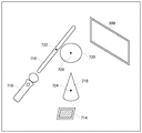
図5は、異なるふたつのARイメージ間の近接度を説明するための図であり、立体映像観察デバイス200を装着したユーザに提示される映像の一例を示す図である。図5は、3種類のマーカ710、714、および300と、それらに対応付けられた3種類のARイメージ716、718、および720を示している。ここでマーカ714は紙に印刷された画像であり、マーカ300は3次元モニタ300における表示領域がマーカとなっている。マーカ710に関連づけられたARイメージ716は光り輝く仮想的な刀身であり、マーカ714に関連づけられたARイメージ718は、円錐形のオブジェクトである。また、マーカ300に関連づけられたARイメージ720は、3次元モニタ300から飛来し3次元モニタ300から離れる方向に移動する球状のオブジェクトである。
FIG. 5 is a diagram for explaining the proximity between two different AR images, and is a diagram illustrating an example of an image presented to a user wearing the stereoscopic
各ARイメージには、ARイメージ間の距離を計測するために定められた距離計測基準点が定められている。図5に示す例では、ARイメージ716の距離計測基準点は符号722で示されている。同様に、ARイメージ718およびARイメージ720の距離計測基準点は、それぞれ符号724および726で示されている。距離計測基準点は、ARイメージ716を構成するポリゴンの表面やARイメージ716付近に存在すればどのような点でもよいが、一例として、近接度取得部560は、ARイメージ716を構成する複数のポリゴンの重心位置に距離計測基準点を設定する。これにより、オブジェクトを構成するポリゴンが複数あったとしてもオブジェクトの位置座標をひとつの座標で表すことができるので、計算コストの抑制と処理速度の向上とが期待できる。
Each AR image has a distance measurement reference point that is determined in order to measure the distance between the AR images. In the example shown in FIG. 5, the distance measurement reference point of the
各ARイメージには、ARイメージ間の衝突を判定するために定められた衝突判定基準半径も定められている。例えば図5に示す例において、ARイメージ716の衝突判定基準半径がr1であり、ARイメージ720の衝突判定基準半径がr2であるとする。また、ARイメージ716の距離計測基準点の座標が(x1,y1,z1)であり、ARイメージ720の距離計測基準点の座標が(x2,y2,z2)であるとする。このとき近接度取得部560は、次の式(1)で示す式の値Eを評価する。
E=(x1−x2)2+(y1−y2)2+(z1−z2)2−(r1+r2)2 (1)
Each AR image also has a collision determination reference radius determined for determining a collision between the AR images. For example, in the example shown in FIG. 5, it is assumed that the collision determination reference radius of the
E = (x 1 −x 2 ) 2 + (y 1 −y 2 ) 2 + (z 1 −z 2 ) 2 − (r 1 + r 2 ) 2 (1)
式(1)において、E=0の場合、ARイメージ716の距離計測基準点とARイメージ720の距離計測基準点との間のユークリッド距離Lが、ARイメージ716の衝突判定基準半径r1とARイメージ720衝突判定基準半径r2との和に等しいことを意味する。このとき、近接度取得部560は、ARイメージ716とARイメージ720とが「接している」とみなす。また、式(1)においてE<0の場合、ARイメージ716の衝突判定基準半径r1とARイメージ720の衝突判定基準半径r2との和が、ARイメージ716の距離計測基準点とARイメージ720の距離計測基準点との間のユークリッド距離Lよりも大きいことを意味する。この場合、近接度取得部560は、ARイメージ716とARイメージ720とが「離れている」とみなす。反対に、式(1)においてE>0の場合、ARイメージ716の衝突判定基準半径r1とARイメージ720の衝突判定基準半径r2との和が、ARイメージ716の距離計測基準点とARイメージ720の距離計測基準点との間のユークリッド距離Lよりも小さいことを意味する。この場合、近接度取得部560は、ARイメージ716とARイメージ720とが「重なっている」とみなす。このように、近接度取得部560が取得するEの値は、ふたつのARイメージ間の近接度を表現する値として利用することができる。
In Eq. (1), when E = 0, the Euclidean distance L between the distance measurement reference point of the
ここで各ARイメージの衝突判定基準半径は、3次元空間中におけるARイメージの大きさを反映する値であればよく、例えば、距離計測基準点からARイメージを構成するポリゴンまでの距離をもとに設定すればよい。より具体的には、距離計測基準点からARイメージを構成する各ポリゴンまでの距離の平均値、距離の最大値または最小値等を、そのARイメージの衝突判定基準半径として採用すればよい。 Here, the collision determination reference radius of each AR image may be a value that reflects the size of the AR image in the three-dimensional space. For example, based on the distance from the distance measurement reference point to the polygon constituting the AR image. Should be set. More specifically, the average value of the distance from the distance measurement reference point to each polygon constituting the AR image, the maximum value or the minimum value of the distance, and the like may be adopted as the collision determination reference radius of the AR image.
図3の説明に戻り、相互作用演出部570は、近接度取得部560が取得した近接度をもとに、ふたつの異なるARイメージ間に生じる相互作用を算出する。ここで「相互作用」とは、ARイメージ間に生じる仮想の物理的あるいは化学的な相互作用と、CGを用いた視覚効果(Visual Effects;VFX)とを含む概念である。前者の例は、剛体同士の衝突における運動量保存則や、軟体同士の衝突であれば両者が結合する現象、あるいは一方のARイメージが燃焼している場合に、燃焼していなかった他方のARイメージに炎が移るといった現象である。後者の例は、一方のARイメージがあらゆるものを切断する刀身である場合にそのARイメージに触れた別のARイメージが切断されるといった効果や、一方のARイメージがあらゆるものを透過する属性が付加されている場合に、他方のARイメージと干渉することなく重なるといった効果である。
Returning to the description of FIG. 3, the
属性管理部540は、ARイメージ生成部526が生成するARイメージそれぞれに付与される仮想的な物理特性や視覚効果を示す情報を含む属性を管理する。ここで属性管理部540が管理する属性は、相互作用演出部570が算出する相互作用に応じて変化する。具体的に、属性管理部540が管理する属性に含まれる物理特性は、ARイメージの3次元空間における位置座標、速度ベクトル、加速度ベクトル、質量、ARイメージの剛性、色、温度、燃焼しているか否か、発光しているか否か、上述した距離計測基準点および衝突基準半径を含む。これらの物理特性は例示であり、属性管理部540は、これらの物理特性を必ずしも全て管理する必要はない。どのような物理特性を管理するかは、コンテント実行部510が再生するコンテントが想定する利用シーンに応じて決定すればよい。
The
相互作用演出部570は、近接度取得部560が取得した近接度をもとに、ふたつのARイメージの物理特性を変化させる。より具体的には、相互作用演出部570は、近接度取得部560が取得した近接度をもとに相互作用を算出し、属性管理部540が、相互作用演出部570が算出した相互作用に応じてARイメージに付与された属性を変化させる。ARイメージ生成部526は、ARイメージの属性が変化したときに生成するイメージを変化させる。
The
例えば図5に示す例において、3次元モニタ300から飛来して3次元モニタ300から離れる方向に移動する球状のオブジェクトであるARイメージ720が、3次元空間上で静止している円錐形のオブジェクトであるARイメージ718に衝突する場合を考える。このとき近接度取得部560がARイメージ720とARイメージ718との間の近接度を計算し、両者が接したと判断したとする。相互作用演出部570は、ARイメージ720に属性である質量および速度ベクトルと、ARイメージ718の属性である質量および速度ベクトルとをもとに、運動量保存則と運動エネルギー保存則とを適用して、衝突後の両者の速度ベクトルを算出する。
For example, in the example shown in FIG. 5, an
属性管理部540は、ARイメージ718およびARイメージ720の属性中の速度ベクトルを、相互作用演出部570が算出した速度ベクトルで書き換える。ARイメージ生成部526は、属性管理部540が書き換えた速度ベクトルにしたがって、ARイメージ718およびARイメージ720が移動するようにARイメージ718およびARイメージ720を変化させる。
The
図6は、異なるふたつのARイメージ間の相互作用を例示する図であり、立体映像観察デバイス200を装着したユーザに提示される映像の一例を示す図である。図6に示す例では、マーカ710に関連づけられた炎を表すARイメージ712が、紙のマーカ728に関連づけられた爆弾を表すARイメージ730の導火線に近接している。図6に示す例ではARイメージ730の導火線に火はついていないが、ユーザがマーカ710を動かすことによって、ARイメージ712がARイメージ730の導火線とが十分に近接したと、近接度取得部560が判断したとする。このとき、相互作用演出部570は、ARイメージ730の導火線が着火したとみなし、属性管理部540はARイメージ730の属性を「燃焼していない」から「燃焼している」に変化させる。この結果、ARイメージ生成部526は、ARイメージ730の導火線に火がついて、時間とともに短くなるようにARイメージ730を変化させる。
FIG. 6 is a diagram illustrating an interaction between two different AR images, and is a diagram illustrating an example of an image presented to a user wearing the stereoscopic
図6に示す例において、所定時間が経過した後に爆弾本体が着火したとする。この時、ARイメージ生成部526は、爆弾を表すARイメージ730は、爆発によっていくつかの破片に分裂されたように生成される。このように、ARイメージ生成部526は、ひとつのARイメージから別のARイメージを新しく生成することもある。ひとつのARイメージから別のARイメージを新しく生成する場合の別の例としては、ピストルを表すARイメージから銃弾を発射するイメージを生成する場合があげられる。あるいは、図6に示す例においてユーザがマーカ710を高速で移動させたとする。この時、マーカ710の移動に応じてARイメージ712の移動ベクトルおよび加速度ベクトルが変化するが、これらの物理特性の単位時間あたりの変化量が所定のしきい値を上回る場合、ARイメージ生成部526は、ARイメージ712とは別の新たなARイメージを生成してもよい。これにより、ユーザの操作に応じて炎が分裂して飛び出るといった演出が可能となる。
In the example shown in FIG. 6, it is assumed that the bomb body ignites after a predetermined time has elapsed. At this time, the AR
ここで、ひとつのARイメージから別のARイメージを新しく生成する場合、新しく生成されるARイメージはもととなるマーカに関連づけられてもよいし、位置情報を用いた別のマーカであってもよい。 Here, when another AR image is newly generated from one AR image, the newly generated AR image may be associated with the original marker, or may be another marker using position information. Good.
図7は、実施の形態に係る映像処理装置500による相互作用演出処理の流れを示すフローチャートである。本フローチャートにおける処理は、例えば映像処理装置500の電源が投入されたときに開始する。
FIG. 7 is a flowchart showing the flow of interaction effect processing by the
近接度取得部560は、マーカ特定部550が特定した第1のマーカに関連づけられた第1ARイメージの位置座標、距離計測基準点、および衝突基準半径を取得する(S2)。近接度取得部560はさらに、マーカ特定部550が特定した第2のマーカに関連づけられた第2ARイメージの位置座標、距離計測基準点、および衝突基準半径も取得する(S4)
The
続いて近接度取得部560は、上述の式(1)にしたがって、第1ARイメージと第2ARイメージとの間の近接度を取得する(S6)。相互作用演出部570は、近接度取得部560が取得した近接度をもとに、第1ARイメージと第2ARイメージとの間の相互作用を計算する(S8)。
Subsequently, the
属性管理部540は、相互作用演出部570が算出した相互作用をもとに、第1ARイメージと第2ARイメージとの属性を変更する(S10)。ARイメージ生成部526は、属性管理部540がした属性変更を、第1ARイメージと第2ARイメージとに反映させる(S12)。ARイメージ生成部526が属性変更をイメージとに反映させると、本フローチャートにおける処理は終了する。
The
以上の構成による映像提示システム100の利用シーンは以下のとおりである。立体映像観察デバイス200を装着して映像提示システム100を利用するユーザが、マーカを移動させることによってマーカに関連づけられたARイメージを移動させ、別のARイメージに近づける。ARイメージ生成部526は相互作用演出部570による相互作用をARイメージに反映させる。これにより、異なるマーカに対するARイメージの接触や衝突等の近接度、およびそのときのARイメージの速度や加速度等の属性に応じて、ARイメージやコンテント実行部510が再生するコンテントの内容に変化を反映させることができる。例えばマーカの加速度を考慮することにより、そのマーカに関連づけられた鞭のARイメージをマーカの動きに応じてしならせる表現などが可能となる。また、ARイメージに付与された特殊な視覚効果を演出することも可能となる。
The usage scenes of the
以上説明したように、実施の形態に係る映像提示システム100によれば、特定の対象物に紐付けて生成される画像間の相互作用を演出する技術を提供することができる。より具体的には、複数のARイメージが相互に影響し合うアプリケーションや、マーカの動きをARイメージに反映させることが可能となる。
As described above, according to the
以上、本発明を実施の形態をもとに説明した。実施の形態は例示であり、それらの各構成要素や各処理プロセスの組合せにいろいろな変形例が可能なこと、またそうした変形例も本発明の範囲にあることは当業者に理解されるところである。 The present invention has been described based on the embodiments. The embodiments are exemplifications, and it will be understood by those skilled in the art that various modifications can be made to combinations of the respective constituent elements and processing processes, and such modifications are within the scope of the present invention. .
(第1の変形例)
上記では、オブジェクトの距離計測基準点としてオブジェクトを構成するポリゴンの重心を採用する場合について説明したが、距離計測基準点はポリゴンの重心の座標には限られない。例えば、オブジェクトを構成するポリゴンのうちひとつのポリゴンの位置座標を代表で用いてもよい。このとき、代表で用いるポリゴンをオブジェクト間の位置関係に応じて適応的に変更してもよい。具体的には、オブジェクトを構成する複数のポリゴンのうち、別のオブジェクトとの距離が最短のポリゴンの位置座標をオブジェクトの座標として採用してもよい。これにより、例えばオブジェクト同士の衝突判定の計算を上述の式(1)を用いることなく、容易かつ正確にすることができる。
(First modification)
In the above description, the case where the center of gravity of the polygon constituting the object is adopted as the distance measurement reference point of the object has been described. However, the distance measurement reference point is not limited to the coordinates of the center of gravity of the polygon. For example, the position coordinates of one polygon among the polygons constituting the object may be used as a representative. At this time, the polygon used as a representative may be adaptively changed according to the positional relationship between the objects. Specifically, among the plurality of polygons constituting the object, the position coordinates of the polygon with the shortest distance from another object may be adopted as the object coordinates. Thereby, for example, calculation of collision determination between objects can be easily and accurately performed without using the above-described equation (1).
(第2の変形例)
上記では、映像提示システム100が3次元モニタ300を含む場合について説明したが、本発明の実施の形態において3次元モニタ300は必須ではなく、立体映像の出力先が立体映像観察デバイス200中の光学透過型HMDだけであっても本発明の実施の形態が成立することは当業者であれば容易に理解できることである。
(Second modification)
The case where the
(第3の変形例)
上記では、ARイメージ同士が接する場合の相互作用を主に説明したが、ARイメージ同士が接しない場合であっても相互作用は算出される。例えば、ユーザがマーカを動かして扇子を表すARイメージを、紙切れを表すARイメージに向かって扇ぐ場合、扇子を表すARイメージと紙切れを表すARイメージとは接しなくても、両者が十分に近接すれば、紙切れを表すARイメージが吹き飛ぶという相互作用が演出される。このように、相互作用はARイメージ同士の近接度に応じて定まる。
(Third Modification)
In the above description, the interaction when the AR images are in contact with each other has been mainly described. However, the interaction is calculated even when the AR images are not in contact with each other. For example, when the user moves the marker to fan an AR image representing a fan toward an AR image representing a piece of paper, the AR image representing the fan and the AR image representing the piece of paper are sufficiently close to each other even if they do not touch each other. For example, the interaction that the AR image representing a piece of paper blows away is produced. Thus, the interaction is determined according to the proximity of the AR images.
(第4の変形例)
上記では、近接度取得部560は異なるふたつのARイメージ間の近接度を取得する場合について説明した、近接度取得部560が算出する近接度は、異なるふたつのARイメージ間の近接度に限らず、あるARイメージとマーカとの間の近接度を求めてもよい。以下、この場合について説明する。
(Fourth modification)
In the above description, the
図8は、あるARイメージとマーカとの間の近接度を説明するための図である。図8に示す例においては、ユーザはマーカ710を操り、マーカ710に関連づけられているARイメージ732を、3次元モニタ300の表示領域に表示されているキャラクタ302に当てることを試みる。図8に示す例はゲームアプリケーションの例であり、ユーザは雷を表すARイメージ732を敵キャラであるキャラクタ302に当てて攻撃することが想定されている。
FIG. 8 is a diagram for explaining the degree of proximity between an AR image and a marker. In the example shown in FIG. 8, the user manipulates the
上述したように、3次元モニタ300の表示領域もひとつのマーカである。近接度取得部560は、ARイメージ732と、マーカである3次元モニタ300の表示領域に表示されている部分的な映像であるキャラクタ302との間で近接度を取得する。すなわち、近接度取得部560は、ARイメージとマーカとの間の近接度を計算する。これにより、例えばコンテント実行部510が再生するコンテントが従来型の2次元のコンテントであり、3次元モニタ300の表示領域に表示される映像が従来型の2次元の映像であったとしても、3次元のARイメージとの相互作用を演出することが可能となる。
As described above, the display area of the three-
100 映像提示システム、 200 立体映像観察デバイス、 202 提示部、 204 撮像素子、 206 筐体、 300 3次元モニタ、 302 キャラクタ、 400 情報処理装置、 500 映像処理装置、 502 オブジェクト取得部、 510 コンテント実行部、 520 映像生成部、 522 制御部、 524 オブジェクト生成部、 526 ARイメージ生成部、 530 出力部、 540 属性管理部、 550 マーカ特定部、 560 近接度取得部、 570 相互作用演出部、 602 直交座標系、 704 座標系。
DESCRIPTION OF
Claims (8)
第1のマーカと第2のマーカとはともに、仮想的な3次元空間における位置、向き、または傾きが変化する映像中の撮像された被写体であり、第1のマーカに紐付けられた第1ARイメージ、第2のマーカに紐付けられた第2ARイメージは、それぞれ第1のマーカ、第2のマーカの位置、向き、または傾きの変化に連動して位置や向き、傾きが変化するオブジェクトであり、第1のマーカに紐付けられた第1ARイメージと、第2のマーカに紐付けられた第2ARイメージとの間の、仮想的な3次元空間における近接度を取得する近接度取得部と、
前記近接度取得部が取得した近接度をもとに、第1ARイメージまたは第2ARイメージとの間に生じる相互作用を算出する相互作用演出部とを含み、
前記ARイメージ生成部は、前記相互作用演出部が算出した相互作用に応じて、第1ARイメージまたは第2ARイメージの少なくともいずれか一方のイメージを変化させることを特徴とする映像処理装置。 An area including a visual field of a user wearing the optically transmissive HMD provided in the optically transmissive HMD that presents an image observed when a three-dimensional image in a virtual three-dimensional space is projected into the real space. An AR image generation unit that generates an AR (Augmented Reality) image to be presented to the optically transmissive HMD using a subject imaged by an imaging element that images a certain subject as a marker;
Both the first marker and the second marker are captured subjects in a video whose position, orientation, or inclination changes in a virtual three-dimensional space, and the first AR associated with the first marker The second AR image linked to the image and the second marker is an object whose position, orientation, and inclination change in conjunction with changes in the position, orientation, and inclination of the first marker and the second marker, respectively. , a first 1AR images tied to the first marker, between the first 2AR image tied to the second marker, and proximity acquisition unit that acquires proximity in a virtual three-dimensional space,
An interaction effect unit that calculates an interaction that occurs between the first AR image or the second AR image based on the proximity acquired by the proximity acquisition unit;
The video image processing apparatus, wherein the AR image generation unit changes at least one of the first AR image and the second AR image according to the interaction calculated by the interaction effect unit.
前記ARイメージ生成部は、前記属性が変化したときに生成するイメージを変化させることを特徴とする請求項1に記載の映像処理装置。 An attribute management unit that manages attributes including virtual physical characteristics assigned to each of the AR images generated by the AR image generation unit;
The video processing apparatus according to claim 1, wherein the AR image generation unit changes an image generated when the attribute changes.
前記相互作用演出部は、前記近接度取得部が取得した近接度をもとに、第1ARイメージの物理特性と第2ARイメージの物理特性とを変化させることを特徴とする請求項2または3に記載の映像処理装置。 The physical property included in the attribute managed by the attribute management unit includes at least one of position coordinates, velocity, acceleration, or mass of the AR image in the virtual three-dimensional space,
The said interaction production | generation part changes the physical characteristic of a 1st AR image, and the physical characteristic of a 2nd AR image based on the proximity degree which the said proximity degree acquisition part acquired, The Claim 2 or 3 characterized by the above-mentioned. The video processing apparatus described.
第1のマーカと第2のマーカとはともに、仮想的な3次元空間における位置、向き、または傾きが変化する映像中の撮像された被写体であり、第1のマーカに紐付けられた第1ARイメージ、第2のマーカに紐付けられた第2ARイメージは、それぞれ第1のマーカ、第2のマーカの位置、向き、または傾きの変化に連動して位置や向き、傾きが変化するオブジェクトであり、第1のマーカに紐付けられた第1ARイメージと、第2のマーカに紐付けられた第2ARイメージとの間の、仮想的な3次元空間における近接度を取得するステップと、
取得した近接度をもとに、第1ARイメージまたは第2ARイメージとの間に生じる相互作用を算出するステップと、
算出した相互作用に応じて、第1ARイメージまたは第2ARイメージの少なくともいずれか一方のイメージを変化させるステップとをプロセッサに実行させることを特徴とする映像処理方法。 An optical transmission type HMD that presents an image observed when a three-dimensional image in a virtual three-dimensional space is projected into a real space, and a subject in a region including the field of view of the user wearing the optical transmission type HMD. Generating an AR image using a subject imaged by the imaging device as a marker, which is presented to a stereoscopic video observation device including an imaging device for imaging;
Both the first marker and the second marker are captured subjects in a video whose position, orientation, or inclination changes in a virtual three-dimensional space, and the first AR associated with the first marker The second AR image linked to the image and the second marker is an object whose position, orientation, and inclination change in conjunction with changes in the position, orientation, and inclination of the first marker and the second marker, respectively. , acquiring a first 1AR images tied to the first marker, between the first 2AR image tied to the second marker, the proximity in the virtual three-dimensional space,
Calculating an interaction occurring between the first AR image and the second AR image based on the obtained proximity;
A video processing method that causes a processor to execute a step of changing at least one of a first AR image and a second AR image in accordance with a calculated interaction.
第1のマーカと第2のマーカとはともに、仮想的な3次元空間における位置、向き、または傾きが変化する映像中の撮像された被写体であり、第1のマーカに紐付けられた第1ARイメージ、第2のマーカに紐付けられた第2ARイメージは、それぞれ第1のマーカ、第2のマーカの位置、向き、または傾きの変化に連動して位置や向き、傾きが変化するオブジェクトであり、第1のマーカに紐付けられた第1ARイメージと、第2のマーカに紐付けられた第2ARイメージとの間の、仮想的な3次元空間における近接度を取得する機能と、
取得した近接度をもとに、第1ARイメージまたは第2ARイメージとの間に生じる相互作用を算出する機能と、
算出した相互作用に応じて、第1ARイメージまたは第2ARイメージの少なくともいずれか一方のイメージを変化させる機能とをコンピュータに実現させることを特徴とするプログラム。 An optical transmission type HMD that presents an image observed when a three-dimensional image in a virtual three-dimensional space is projected into a real space, and a subject in a region including the field of view of the user wearing the optical transmission type HMD. A function of generating an AR image using a subject imaged by the imaging device as a marker, which is presented to a stereoscopic video observation device including an imaging device for imaging;
Both the first marker and the second marker are captured subjects in a video whose position, orientation, or inclination changes in a virtual three-dimensional space, and the first AR associated with the first marker The second AR image linked to the image and the second marker is an object whose position, orientation, and inclination change in conjunction with changes in the position, orientation, and inclination of the first marker and the second marker, respectively. , a first 1AR images tied to the first marker, between the first 2AR image tied to the second marker, the function of acquiring the proximity in the virtual three-dimensional space,
A function for calculating an interaction between the first AR image and the second AR image based on the obtained proximity;
A program for causing a computer to realize a function of changing at least one of the first AR image and the second AR image in accordance with the calculated interaction.
前記光学透過型HMDに備えられ、前記光学透過型HMDを装着するユーザの視野を含む領域にある被写体を撮像する撮像素子と、
前記撮像素子が撮像した被写体をマーカとして、前記光学透過型HMDに提示させるAR(Augmented Reality)イメージを生成するARイメージ生成部と、
第1のマーカと第2のマーカとはともに、仮想的な3次元空間における位置、向き、または傾きが変化する映像中の撮像された被写体であり、第1のマーカに紐付けられた第1ARイメージ、第2のマーカに紐付けられた第2ARイメージは、それぞれ第1のマーカ、第2のマーカの位置、向き、または傾きの変化に連動して位置や向き、傾きが変化するオブジェクトであり、第1のマーカに紐付けられた第1ARイメージと、第2のマーカに紐付けられた第2ARイメージとの間の、仮想的な3次元空間における近接度を取得する近接度取得部と、
前記近接度取得部が取得した近接度をもとに、第1ARイメージまたは第2ARイメージとの間に生じる相互作用を算出する相互作用演出部とを含み、
前記ARイメージ生成部は、前記相互作用演出部が算出した相互作用に応じて、第1ARイメージまたは第2ARイメージの少なくともいずれか一方のイメージを変化させることを特徴とする映像処理システム。 An optically transmissive HMD that presents an image observed when a three-dimensional image in a virtual three-dimensional space is projected into a real space;
An image sensor that is provided in the optical transmission type HMD and images a subject in a region including a field of view of a user wearing the optical transmission type HMD;
An AR image generating unit that generates an AR (Augmented Reality) image to be presented to the optically transmissive HMD using a subject imaged by the image sensor as a marker;
Both the first marker and the second marker are captured subjects in a video whose position, orientation, or inclination changes in a virtual three-dimensional space, and the first AR associated with the first marker The second AR image linked to the image and the second marker is an object whose position, orientation, and inclination change in conjunction with changes in the position, orientation, and inclination of the first marker and the second marker, respectively. , a first 1AR images tied to the first marker, between the first 2AR image tied to the second marker, and proximity acquisition unit that acquires proximity in a virtual three-dimensional space,
An interaction effect unit that calculates an interaction that occurs between the first AR image or the second AR image based on the proximity acquired by the proximity acquisition unit;
The video image processing system, wherein the AR image generation unit changes at least one of the first AR image and the second AR image according to the interaction calculated by the interaction effect unit.
Priority Applications (6)
| Application Number | Priority Date | Filing Date | Title |
|---|---|---|---|
| JP2012147344A JP5891125B2 (en) | 2012-06-29 | 2012-06-29 | Video processing apparatus, video processing method, and video processing system |
| CN201380032960.XA CN104380347B (en) | 2012-06-29 | 2013-04-17 | Video processing equipment, method for processing video frequency and processing system for video |
| EP13810089.6A EP2869274A4 (en) | 2012-06-29 | 2013-04-17 | Video processing device, video processing method, and video processing system |
| CN201711039232.8A CN107844196B (en) | 2012-06-29 | 2013-04-17 | Video processing apparatus, video processing method, and video processing system |
| US14/406,919 US9639989B2 (en) | 2012-06-29 | 2013-04-17 | Video processing device, video processing method, and video processing system |
| PCT/JP2013/002605 WO2014002346A1 (en) | 2012-06-29 | 2013-04-17 | Video processing device, video processing method, and video processing system |
Applications Claiming Priority (1)
| Application Number | Priority Date | Filing Date | Title |
|---|---|---|---|
| JP2012147344A JP5891125B2 (en) | 2012-06-29 | 2012-06-29 | Video processing apparatus, video processing method, and video processing system |
Related Child Applications (1)
| Application Number | Title | Priority Date | Filing Date |
|---|---|---|---|
| JP2016031175A Division JP6161749B2 (en) | 2016-02-22 | 2016-02-22 | Video processing apparatus, video processing method, and video processing system |
Publications (3)
| Publication Number | Publication Date |
|---|---|
| JP2014010664A JP2014010664A (en) | 2014-01-20 |
| JP2014010664A5 JP2014010664A5 (en) | 2015-07-16 |
| JP5891125B2 true JP5891125B2 (en) | 2016-03-22 |
Family
ID=49782553
Family Applications (1)
| Application Number | Title | Priority Date | Filing Date |
|---|---|---|---|
| JP2012147344A Active JP5891125B2 (en) | 2012-06-29 | 2012-06-29 | Video processing apparatus, video processing method, and video processing system |
Country Status (5)
| Country | Link |
|---|---|
| US (1) | US9639989B2 (en) |
| EP (1) | EP2869274A4 (en) |
| JP (1) | JP5891125B2 (en) |
| CN (2) | CN107844196B (en) |
| WO (1) | WO2014002346A1 (en) |
Families Citing this family (24)
| Publication number | Priority date | Publication date | Assignee | Title |
|---|---|---|---|---|
| JP5891125B2 (en) * | 2012-06-29 | 2016-03-22 | 株式会社ソニー・コンピュータエンタテインメント | Video processing apparatus, video processing method, and video processing system |
| KR101483054B1 (en) * | 2014-05-31 | 2015-01-16 | 연세대학교 산학협력단 | Mobile -based augmented reality authoring system and method for interaction |
| CN105872526B (en) * | 2015-01-21 | 2017-10-31 | 成都理想境界科技有限公司 | Binocular AR wears display device and its method for information display |
| KR101618004B1 (en) * | 2015-01-27 | 2016-05-09 | 가톨릭대학교 산학협력단 | Interactive content providing apparatus based on the virtual reality and method thereof |
| JP6336930B2 (en) | 2015-02-16 | 2018-06-06 | 富士フイルム株式会社 | Virtual object display device, method, program, and system |
| GB2535727A (en) * | 2015-02-25 | 2016-08-31 | Bae Systems Plc | Interactive information system |
| US20160253891A1 (en) * | 2015-02-27 | 2016-09-01 | Elwha Llc | Device that determines that a subject may contact a sensed object and that warns of the potential contact |
| US10038838B2 (en) | 2015-05-29 | 2018-07-31 | Hover Inc. | Directed image capture |
| WO2017001146A1 (en) * | 2015-06-29 | 2017-01-05 | Essilor International (Compagnie Générale d'Optique) | A scene image analysis module |
| US9922463B2 (en) | 2015-08-07 | 2018-03-20 | Microsoft Technology Licensing, Llc | Virtually visualizing energy |
| US20170039986A1 (en) * | 2015-08-07 | 2017-02-09 | Microsoft Technology Licensing, Llc | Mixed Reality Social Interactions |
| US20170038829A1 (en) * | 2015-08-07 | 2017-02-09 | Microsoft Technology Licensing, Llc | Social interaction for remote communication |
| US10515482B2 (en) | 2015-08-24 | 2019-12-24 | Pcms Holdings, Inc. | Systems and methods for enhancing augmented reality experience with dynamic output mapping |
| EP3360029B1 (en) | 2015-10-08 | 2019-11-13 | PCMS Holdings, Inc. | Methods and systems of automatic calibration for dynamic display configurations |
| US10616662B2 (en) | 2016-02-10 | 2020-04-07 | Disney Enterprises, Inc. | Systems and methods to provide video and control signals over an internet protocol communications network |
| US10788966B2 (en) * | 2016-02-10 | 2020-09-29 | Disney Enterprises, Inc. | Systems and methods for interacting with a virtual interface |
| US10163198B2 (en) | 2016-02-26 | 2018-12-25 | Samsung Electronics Co., Ltd. | Portable image device for simulating interaction with electronic device |
| US10169918B2 (en) * | 2016-06-24 | 2019-01-01 | Microsoft Technology Licensing, Llc | Relational rendering of holographic objects |
| US11014001B2 (en) * | 2018-03-05 | 2021-05-25 | Sony Interactive Entertainment LLC | Building virtual reality (VR) gaming environments using real-world virtual reality maps |
| US10695667B2 (en) * | 2018-03-14 | 2020-06-30 | Sony Interactive Entertainment LLC | Pro gaming AR visor and method for parsing context specific HUD content from a video stream |
| US10777012B2 (en) * | 2018-09-27 | 2020-09-15 | Universal City Studios Llc | Display systems in an entertainment environment |
| US10776954B2 (en) | 2018-10-08 | 2020-09-15 | Microsoft Technology Licensing, Llc | Real-world anchor in a virtual-reality environment |
| US11741673B2 (en) | 2018-11-30 | 2023-08-29 | Interdigital Madison Patent Holdings, Sas | Method for mirroring 3D objects to light field displays |
| JP7443014B2 (en) | 2019-10-08 | 2024-03-05 | 大豊精機株式会社 | robot arm testing equipment |
Family Cites Families (26)
| Publication number | Priority date | Publication date | Assignee | Title |
|---|---|---|---|---|
| JP3401897B2 (en) | 1994-02-16 | 2003-04-28 | 株式会社セガ | Collision determination processing system and image processing apparatus using the same |
| CN1161087A (en) | 1994-08-10 | 1997-10-01 | 实质(Ip)有限公司 | Head mounted display optics |
| JP3486536B2 (en) * | 1997-09-01 | 2004-01-13 | キヤノン株式会社 | Mixed reality presentation apparatus and method |
| US6522312B2 (en) | 1997-09-01 | 2003-02-18 | Canon Kabushiki Kaisha | Apparatus for presenting mixed reality shared among operators |
| JP2000350865A (en) | 1999-06-11 | 2000-12-19 | Mr System Kenkyusho:Kk | Game device for composite real space, image processing method therefor and program storage medium |
| JP3413127B2 (en) * | 1999-06-11 | 2003-06-03 | キヤノン株式会社 | Mixed reality device and mixed reality presentation method |
| ATE543546T1 (en) | 1999-06-11 | 2012-02-15 | Canon Kk | DEVICE AND METHOD FOR REPRESENTING A SPACE SHARED BY SEVERAL USERS WHERE REALITY IS PARTIALLY INCLUDED, CORRESPONDING GAME DEVICE AND CORRESPONDING INTERFACE METHOD |
| US6771841B1 (en) * | 1999-12-29 | 2004-08-03 | Intel Corporation | Determining a bounding shape for a collection of points |
| JP3584230B2 (en) * | 2001-09-28 | 2004-11-04 | キヤノン株式会社 | Video experience system, information processing method and program |
| US20030062675A1 (en) | 2001-09-28 | 2003-04-03 | Canon Kabushiki Kaisha | Image experiencing system and information processing method |
| CN2667920Y (en) | 2003-12-26 | 2005-01-05 | 沈阳工业学院 | Optical double view-field three-dimensional helmet display device |
| US7991220B2 (en) * | 2004-09-01 | 2011-08-02 | Sony Computer Entertainment Inc. | Augmented reality game system using identification information to display a virtual object in association with a position of a real object |
| JP3844482B2 (en) | 2004-09-01 | 2006-11-15 | 株式会社ソニー・コンピュータエンタテインメント | Image processing device |
| JP4335160B2 (en) | 2005-03-02 | 2009-09-30 | 任天堂株式会社 | Collision judgment program and collision judgment device |
| ATE428154T1 (en) | 2005-05-03 | 2009-04-15 | Seac02 S R L | AUGMENTED REALITY SYSTEM WITH IDENTIFICATION OF THE REAL MARKING OF THE OBJECT |
| JP4689344B2 (en) * | 2005-05-11 | 2011-05-25 | キヤノン株式会社 | Information processing method and information processing apparatus |
| US7773098B2 (en) | 2005-05-11 | 2010-08-10 | Canon Kabushiki Kaisha | Virtual reality presentation apparatus and method |
| CN100399835C (en) | 2005-09-29 | 2008-07-02 | 北京理工大学 | Enhancement actual fixed-point observation system for field digital three-dimensional reestablishing |
| KR100809479B1 (en) * | 2006-07-27 | 2008-03-03 | 한국전자통신연구원 | Face mounted display apparatus and method for mixed reality environment |
| JP2010026818A (en) | 2008-07-18 | 2010-02-04 | Geisha Tokyo Entertainment Inc | Image processing program, image processor, and image processing method |
| CN101539804A (en) * | 2009-03-11 | 2009-09-23 | 上海大学 | Real time human-machine interaction method and system based on augmented virtual reality and anomalous screen |
| JP5627973B2 (en) * | 2010-09-24 | 2014-11-19 | 任天堂株式会社 | Program, apparatus, system and method for game processing |
| US8625200B2 (en) * | 2010-10-21 | 2014-01-07 | Lockheed Martin Corporation | Head-mounted display apparatus employing one or more reflective optical surfaces |
| JP5472056B2 (en) * | 2010-11-19 | 2014-04-16 | コニカミノルタ株式会社 | Display system, display processing apparatus, display method, and display program |
| US8189263B1 (en) * | 2011-04-01 | 2012-05-29 | Google Inc. | Image waveguide with mirror arrays |
| JP5891125B2 (en) * | 2012-06-29 | 2016-03-22 | 株式会社ソニー・コンピュータエンタテインメント | Video processing apparatus, video processing method, and video processing system |
-
2012
- 2012-06-29 JP JP2012147344A patent/JP5891125B2/en active Active
-
2013
- 2013-04-17 CN CN201711039232.8A patent/CN107844196B/en active Active
- 2013-04-17 CN CN201380032960.XA patent/CN104380347B/en active Active
- 2013-04-17 WO PCT/JP2013/002605 patent/WO2014002346A1/en active Application Filing
- 2013-04-17 EP EP13810089.6A patent/EP2869274A4/en not_active Ceased
- 2013-04-17 US US14/406,919 patent/US9639989B2/en active Active
Also Published As
| Publication number | Publication date |
|---|---|
| US20150170419A1 (en) | 2015-06-18 |
| EP2869274A1 (en) | 2015-05-06 |
| EP2869274A4 (en) | 2016-01-27 |
| CN107844196B (en) | 2020-12-01 |
| WO2014002346A1 (en) | 2014-01-03 |
| US9639989B2 (en) | 2017-05-02 |
| JP2014010664A (en) | 2014-01-20 |
| CN107844196A (en) | 2018-03-27 |
| CN104380347A (en) | 2015-02-25 |
| CN104380347B (en) | 2017-12-05 |
Similar Documents
| Publication | Publication Date | Title |
|---|---|---|
| JP5891125B2 (en) | Video processing apparatus, video processing method, and video processing system | |
| JP5483761B2 (en) | Video output device, stereoscopic video observation device, video presentation system, and video output method | |
| US10643389B2 (en) | Mechanism to give holographic objects saliency in multiple spaces | |
| JP6813501B2 (en) | Privacy-sensitive consumer cameras coupled to augmented reality systems | |
| US10453248B2 (en) | Method of providing virtual space and system for executing the same | |
| US9122053B2 (en) | Realistic occlusion for a head mounted augmented reality display | |
| JP2022502800A (en) | Systems and methods for augmented reality | |
| US20180189549A1 (en) | Method for communication via virtual space, program for executing the method on computer, and information processing apparatus for executing the program | |
| JP5602618B2 (en) | Image processing program, image processing apparatus, image processing system, and image processing method | |
| US9183676B2 (en) | Displaying a collision between real and virtual objects | |
| JP6340017B2 (en) | An imaging system that synthesizes a subject and a three-dimensional virtual space in real time | |
| US9662583B2 (en) | Portable type game device and method for controlling portable type game device | |
| CN106537909B (en) | Stereo-picture presentation device, stereo-picture rendering method and head-mounted display | |
| US11738270B2 (en) | Simulation system, processing method, and information storage medium | |
| JP2016525741A (en) | Shared holographic and private holographic objects | |
| US20180357817A1 (en) | Information processing method, program, and computer | |
| TW201447375A (en) | Head wearable electronic device and method for augmented reality | |
| CN104995583A (en) | Direct interaction system for mixed reality environments | |
| CN110506249A (en) | Information processing equipment, information processing method and recording medium | |
| JP6161749B2 (en) | Video processing apparatus, video processing method, and video processing system | |
| CN110709897A (en) | Shadow generation for image content inserted into an image | |
| US20180190010A1 (en) | Method for providing virtual space, program for executing the method on computer, and information processing apparatus for executing the program | |
| US20180189555A1 (en) | Method executed on computer for communicating via virtual space, program for executing the method on computer, and computer apparatus therefor | |
| JP2011215919A (en) | Program, information storage medium and image generation system |
Legal Events
| Date | Code | Title | Description |
|---|---|---|---|
| A521 | Request for written amendment filed |
Free format text: JAPANESE INTERMEDIATE CODE: A523 Effective date: 20150527 |
|
| A621 | Written request for application examination |
Free format text: JAPANESE INTERMEDIATE CODE: A621 Effective date: 20150527 |
|
| A131 | Notification of reasons for refusal |
Free format text: JAPANESE INTERMEDIATE CODE: A131 Effective date: 20151117 |
|
| A521 | Request for written amendment filed |
Free format text: JAPANESE INTERMEDIATE CODE: A523 Effective date: 20151225 |
|
| TRDD | Decision of grant or rejection written | ||
| A01 | Written decision to grant a patent or to grant a registration (utility model) |
Free format text: JAPANESE INTERMEDIATE CODE: A01 Effective date: 20160126 |
|
| A61 | First payment of annual fees (during grant procedure) |
Free format text: JAPANESE INTERMEDIATE CODE: A61 Effective date: 20160222 |
|
| R150 | Certificate of patent or registration of utility model |
Ref document number: 5891125 Country of ref document: JP Free format text: JAPANESE INTERMEDIATE CODE: R150 |
|
| R250 | Receipt of annual fees |
Free format text: JAPANESE INTERMEDIATE CODE: R250 |
|
| R250 | Receipt of annual fees |
Free format text: JAPANESE INTERMEDIATE CODE: R250 |
|
| R250 | Receipt of annual fees |
Free format text: JAPANESE INTERMEDIATE CODE: R250 |
|
| R250 | Receipt of annual fees |
Free format text: JAPANESE INTERMEDIATE CODE: R250 |