JP5884802B2 - Control device for hybrid vehicle - Google Patents
Control device for hybrid vehicle Download PDFInfo
- Publication number
- JP5884802B2 JP5884802B2 JP2013196952A JP2013196952A JP5884802B2 JP 5884802 B2 JP5884802 B2 JP 5884802B2 JP 2013196952 A JP2013196952 A JP 2013196952A JP 2013196952 A JP2013196952 A JP 2013196952A JP 5884802 B2 JP5884802 B2 JP 5884802B2
- Authority
- JP
- Japan
- Prior art keywords
- power
- storage device
- temperature
- power storage
- hybrid vehicle
- Prior art date
- Legal status (The legal status is an assumption and is not a legal conclusion. Google has not performed a legal analysis and makes no representation as to the accuracy of the status listed.)
- Active
Links
Images


Classifications
-
- B—PERFORMING OPERATIONS; TRANSPORTING
- B60—VEHICLES IN GENERAL
- B60L—PROPULSION OF ELECTRICALLY-PROPELLED VEHICLES; SUPPLYING ELECTRIC POWER FOR AUXILIARY EQUIPMENT OF ELECTRICALLY-PROPELLED VEHICLES; ELECTRODYNAMIC BRAKE SYSTEMS FOR VEHICLES IN GENERAL; MAGNETIC SUSPENSION OR LEVITATION FOR VEHICLES; MONITORING OPERATING VARIABLES OF ELECTRICALLY-PROPELLED VEHICLES; ELECTRIC SAFETY DEVICES FOR ELECTRICALLY-PROPELLED VEHICLES
- B60L1/00—Supplying electric power to auxiliary equipment of vehicles
- B60L1/003—Supplying electric power to auxiliary equipment of vehicles to auxiliary motors, e.g. for pumps, compressors
-
- B—PERFORMING OPERATIONS; TRANSPORTING
- B60—VEHICLES IN GENERAL
- B60L—PROPULSION OF ELECTRICALLY-PROPELLED VEHICLES; SUPPLYING ELECTRIC POWER FOR AUXILIARY EQUIPMENT OF ELECTRICALLY-PROPELLED VEHICLES; ELECTRODYNAMIC BRAKE SYSTEMS FOR VEHICLES IN GENERAL; MAGNETIC SUSPENSION OR LEVITATION FOR VEHICLES; MONITORING OPERATING VARIABLES OF ELECTRICALLY-PROPELLED VEHICLES; ELECTRIC SAFETY DEVICES FOR ELECTRICALLY-PROPELLED VEHICLES
- B60L1/00—Supplying electric power to auxiliary equipment of vehicles
- B60L1/02—Supplying electric power to auxiliary equipment of vehicles to electric heating circuits
- B60L1/04—Supplying electric power to auxiliary equipment of vehicles to electric heating circuits fed by the power supply line
- B60L1/06—Supplying electric power to auxiliary equipment of vehicles to electric heating circuits fed by the power supply line using only one supply
-
- B—PERFORMING OPERATIONS; TRANSPORTING
- B60—VEHICLES IN GENERAL
- B60L—PROPULSION OF ELECTRICALLY-PROPELLED VEHICLES; SUPPLYING ELECTRIC POWER FOR AUXILIARY EQUIPMENT OF ELECTRICALLY-PROPELLED VEHICLES; ELECTRODYNAMIC BRAKE SYSTEMS FOR VEHICLES IN GENERAL; MAGNETIC SUSPENSION OR LEVITATION FOR VEHICLES; MONITORING OPERATING VARIABLES OF ELECTRICALLY-PROPELLED VEHICLES; ELECTRIC SAFETY DEVICES FOR ELECTRICALLY-PROPELLED VEHICLES
- B60L15/00—Methods, circuits, or devices for controlling the traction-motor speed of electrically-propelled vehicles
- B60L15/20—Methods, circuits, or devices for controlling the traction-motor speed of electrically-propelled vehicles for control of the vehicle or its driving motor to achieve a desired performance, e.g. speed, torque, programmed variation of speed
- B60L15/2009—Methods, circuits, or devices for controlling the traction-motor speed of electrically-propelled vehicles for control of the vehicle or its driving motor to achieve a desired performance, e.g. speed, torque, programmed variation of speed for braking
-
- B—PERFORMING OPERATIONS; TRANSPORTING
- B60—VEHICLES IN GENERAL
- B60L—PROPULSION OF ELECTRICALLY-PROPELLED VEHICLES; SUPPLYING ELECTRIC POWER FOR AUXILIARY EQUIPMENT OF ELECTRICALLY-PROPELLED VEHICLES; ELECTRODYNAMIC BRAKE SYSTEMS FOR VEHICLES IN GENERAL; MAGNETIC SUSPENSION OR LEVITATION FOR VEHICLES; MONITORING OPERATING VARIABLES OF ELECTRICALLY-PROPELLED VEHICLES; ELECTRIC SAFETY DEVICES FOR ELECTRICALLY-PROPELLED VEHICLES
- B60L3/00—Electric devices on electrically-propelled vehicles for safety purposes; Monitoring operating variables, e.g. speed, deceleration or energy consumption
- B60L3/0023—Detecting, eliminating, remedying or compensating for drive train abnormalities, e.g. failures within the drive train
- B60L3/0046—Detecting, eliminating, remedying or compensating for drive train abnormalities, e.g. failures within the drive train relating to electric energy storage systems, e.g. batteries or capacitors
-
- B—PERFORMING OPERATIONS; TRANSPORTING
- B60—VEHICLES IN GENERAL
- B60L—PROPULSION OF ELECTRICALLY-PROPELLED VEHICLES; SUPPLYING ELECTRIC POWER FOR AUXILIARY EQUIPMENT OF ELECTRICALLY-PROPELLED VEHICLES; ELECTRODYNAMIC BRAKE SYSTEMS FOR VEHICLES IN GENERAL; MAGNETIC SUSPENSION OR LEVITATION FOR VEHICLES; MONITORING OPERATING VARIABLES OF ELECTRICALLY-PROPELLED VEHICLES; ELECTRIC SAFETY DEVICES FOR ELECTRICALLY-PROPELLED VEHICLES
- B60L3/00—Electric devices on electrically-propelled vehicles for safety purposes; Monitoring operating variables, e.g. speed, deceleration or energy consumption
- B60L3/0023—Detecting, eliminating, remedying or compensating for drive train abnormalities, e.g. failures within the drive train
- B60L3/0069—Detecting, eliminating, remedying or compensating for drive train abnormalities, e.g. failures within the drive train relating to the isolation, e.g. ground fault or leak current
-
- B—PERFORMING OPERATIONS; TRANSPORTING
- B60—VEHICLES IN GENERAL
- B60L—PROPULSION OF ELECTRICALLY-PROPELLED VEHICLES; SUPPLYING ELECTRIC POWER FOR AUXILIARY EQUIPMENT OF ELECTRICALLY-PROPELLED VEHICLES; ELECTRODYNAMIC BRAKE SYSTEMS FOR VEHICLES IN GENERAL; MAGNETIC SUSPENSION OR LEVITATION FOR VEHICLES; MONITORING OPERATING VARIABLES OF ELECTRICALLY-PROPELLED VEHICLES; ELECTRIC SAFETY DEVICES FOR ELECTRICALLY-PROPELLED VEHICLES
- B60L3/00—Electric devices on electrically-propelled vehicles for safety purposes; Monitoring operating variables, e.g. speed, deceleration or energy consumption
- B60L3/04—Cutting off the power supply under fault conditions
-
- B—PERFORMING OPERATIONS; TRANSPORTING
- B60—VEHICLES IN GENERAL
- B60L—PROPULSION OF ELECTRICALLY-PROPELLED VEHICLES; SUPPLYING ELECTRIC POWER FOR AUXILIARY EQUIPMENT OF ELECTRICALLY-PROPELLED VEHICLES; ELECTRODYNAMIC BRAKE SYSTEMS FOR VEHICLES IN GENERAL; MAGNETIC SUSPENSION OR LEVITATION FOR VEHICLES; MONITORING OPERATING VARIABLES OF ELECTRICALLY-PROPELLED VEHICLES; ELECTRIC SAFETY DEVICES FOR ELECTRICALLY-PROPELLED VEHICLES
- B60L50/00—Electric propulsion with power supplied within the vehicle
- B60L50/10—Electric propulsion with power supplied within the vehicle using propulsion power supplied by engine-driven generators, e.g. generators driven by combustion engines
- B60L50/16—Electric propulsion with power supplied within the vehicle using propulsion power supplied by engine-driven generators, e.g. generators driven by combustion engines with provision for separate direct mechanical propulsion
-
- B—PERFORMING OPERATIONS; TRANSPORTING
- B60—VEHICLES IN GENERAL
- B60L—PROPULSION OF ELECTRICALLY-PROPELLED VEHICLES; SUPPLYING ELECTRIC POWER FOR AUXILIARY EQUIPMENT OF ELECTRICALLY-PROPELLED VEHICLES; ELECTRODYNAMIC BRAKE SYSTEMS FOR VEHICLES IN GENERAL; MAGNETIC SUSPENSION OR LEVITATION FOR VEHICLES; MONITORING OPERATING VARIABLES OF ELECTRICALLY-PROPELLED VEHICLES; ELECTRIC SAFETY DEVICES FOR ELECTRICALLY-PROPELLED VEHICLES
- B60L50/00—Electric propulsion with power supplied within the vehicle
- B60L50/40—Electric propulsion with power supplied within the vehicle using propulsion power supplied by capacitors
-
- B—PERFORMING OPERATIONS; TRANSPORTING
- B60—VEHICLES IN GENERAL
- B60L—PROPULSION OF ELECTRICALLY-PROPELLED VEHICLES; SUPPLYING ELECTRIC POWER FOR AUXILIARY EQUIPMENT OF ELECTRICALLY-PROPELLED VEHICLES; ELECTRODYNAMIC BRAKE SYSTEMS FOR VEHICLES IN GENERAL; MAGNETIC SUSPENSION OR LEVITATION FOR VEHICLES; MONITORING OPERATING VARIABLES OF ELECTRICALLY-PROPELLED VEHICLES; ELECTRIC SAFETY DEVICES FOR ELECTRICALLY-PROPELLED VEHICLES
- B60L50/00—Electric propulsion with power supplied within the vehicle
- B60L50/50—Electric propulsion with power supplied within the vehicle using propulsion power supplied by batteries or fuel cells
- B60L50/60—Electric propulsion with power supplied within the vehicle using propulsion power supplied by batteries or fuel cells using power supplied by batteries
- B60L50/61—Electric propulsion with power supplied within the vehicle using propulsion power supplied by batteries or fuel cells using power supplied by batteries by batteries charged by engine-driven generators, e.g. series hybrid electric vehicles
-
- B—PERFORMING OPERATIONS; TRANSPORTING
- B60—VEHICLES IN GENERAL
- B60L—PROPULSION OF ELECTRICALLY-PROPELLED VEHICLES; SUPPLYING ELECTRIC POWER FOR AUXILIARY EQUIPMENT OF ELECTRICALLY-PROPELLED VEHICLES; ELECTRODYNAMIC BRAKE SYSTEMS FOR VEHICLES IN GENERAL; MAGNETIC SUSPENSION OR LEVITATION FOR VEHICLES; MONITORING OPERATING VARIABLES OF ELECTRICALLY-PROPELLED VEHICLES; ELECTRIC SAFETY DEVICES FOR ELECTRICALLY-PROPELLED VEHICLES
- B60L53/00—Methods of charging batteries, specially adapted for electric vehicles; Charging stations or on-board charging equipment therefor; Exchange of energy storage elements in electric vehicles
- B60L53/10—Methods of charging batteries, specially adapted for electric vehicles; Charging stations or on-board charging equipment therefor; Exchange of energy storage elements in electric vehicles characterised by the energy transfer between the charging station and the vehicle
- B60L53/14—Conductive energy transfer
-
- B—PERFORMING OPERATIONS; TRANSPORTING
- B60—VEHICLES IN GENERAL
- B60L—PROPULSION OF ELECTRICALLY-PROPELLED VEHICLES; SUPPLYING ELECTRIC POWER FOR AUXILIARY EQUIPMENT OF ELECTRICALLY-PROPELLED VEHICLES; ELECTRODYNAMIC BRAKE SYSTEMS FOR VEHICLES IN GENERAL; MAGNETIC SUSPENSION OR LEVITATION FOR VEHICLES; MONITORING OPERATING VARIABLES OF ELECTRICALLY-PROPELLED VEHICLES; ELECTRIC SAFETY DEVICES FOR ELECTRICALLY-PROPELLED VEHICLES
- B60L53/00—Methods of charging batteries, specially adapted for electric vehicles; Charging stations or on-board charging equipment therefor; Exchange of energy storage elements in electric vehicles
- B60L53/60—Monitoring or controlling charging stations
- B60L53/63—Monitoring or controlling charging stations in response to network capacity
-
- B—PERFORMING OPERATIONS; TRANSPORTING
- B60—VEHICLES IN GENERAL
- B60L—PROPULSION OF ELECTRICALLY-PROPELLED VEHICLES; SUPPLYING ELECTRIC POWER FOR AUXILIARY EQUIPMENT OF ELECTRICALLY-PROPELLED VEHICLES; ELECTRODYNAMIC BRAKE SYSTEMS FOR VEHICLES IN GENERAL; MAGNETIC SUSPENSION OR LEVITATION FOR VEHICLES; MONITORING OPERATING VARIABLES OF ELECTRICALLY-PROPELLED VEHICLES; ELECTRIC SAFETY DEVICES FOR ELECTRICALLY-PROPELLED VEHICLES
- B60L53/00—Methods of charging batteries, specially adapted for electric vehicles; Charging stations or on-board charging equipment therefor; Exchange of energy storage elements in electric vehicles
- B60L53/60—Monitoring or controlling charging stations
- B60L53/65—Monitoring or controlling charging stations involving identification of vehicles or their battery types
-
- B—PERFORMING OPERATIONS; TRANSPORTING
- B60—VEHICLES IN GENERAL
- B60L—PROPULSION OF ELECTRICALLY-PROPELLED VEHICLES; SUPPLYING ELECTRIC POWER FOR AUXILIARY EQUIPMENT OF ELECTRICALLY-PROPELLED VEHICLES; ELECTRODYNAMIC BRAKE SYSTEMS FOR VEHICLES IN GENERAL; MAGNETIC SUSPENSION OR LEVITATION FOR VEHICLES; MONITORING OPERATING VARIABLES OF ELECTRICALLY-PROPELLED VEHICLES; ELECTRIC SAFETY DEVICES FOR ELECTRICALLY-PROPELLED VEHICLES
- B60L55/00—Arrangements for supplying energy stored within a vehicle to a power network, i.e. vehicle-to-grid [V2G] arrangements
-
- B—PERFORMING OPERATIONS; TRANSPORTING
- B60—VEHICLES IN GENERAL
- B60L—PROPULSION OF ELECTRICALLY-PROPELLED VEHICLES; SUPPLYING ELECTRIC POWER FOR AUXILIARY EQUIPMENT OF ELECTRICALLY-PROPELLED VEHICLES; ELECTRODYNAMIC BRAKE SYSTEMS FOR VEHICLES IN GENERAL; MAGNETIC SUSPENSION OR LEVITATION FOR VEHICLES; MONITORING OPERATING VARIABLES OF ELECTRICALLY-PROPELLED VEHICLES; ELECTRIC SAFETY DEVICES FOR ELECTRICALLY-PROPELLED VEHICLES
- B60L58/00—Methods or circuit arrangements for monitoring or controlling batteries or fuel cells, specially adapted for electric vehicles
- B60L58/10—Methods or circuit arrangements for monitoring or controlling batteries or fuel cells, specially adapted for electric vehicles for monitoring or controlling batteries
- B60L58/12—Methods or circuit arrangements for monitoring or controlling batteries or fuel cells, specially adapted for electric vehicles for monitoring or controlling batteries responding to state of charge [SoC]
-
- B—PERFORMING OPERATIONS; TRANSPORTING
- B60—VEHICLES IN GENERAL
- B60L—PROPULSION OF ELECTRICALLY-PROPELLED VEHICLES; SUPPLYING ELECTRIC POWER FOR AUXILIARY EQUIPMENT OF ELECTRICALLY-PROPELLED VEHICLES; ELECTRODYNAMIC BRAKE SYSTEMS FOR VEHICLES IN GENERAL; MAGNETIC SUSPENSION OR LEVITATION FOR VEHICLES; MONITORING OPERATING VARIABLES OF ELECTRICALLY-PROPELLED VEHICLES; ELECTRIC SAFETY DEVICES FOR ELECTRICALLY-PROPELLED VEHICLES
- B60L7/00—Electrodynamic brake systems for vehicles in general
- B60L7/10—Dynamic electric regenerative braking
- B60L7/14—Dynamic electric regenerative braking for vehicles propelled by ac motors
-
- B—PERFORMING OPERATIONS; TRANSPORTING
- B60—VEHICLES IN GENERAL
- B60L—PROPULSION OF ELECTRICALLY-PROPELLED VEHICLES; SUPPLYING ELECTRIC POWER FOR AUXILIARY EQUIPMENT OF ELECTRICALLY-PROPELLED VEHICLES; ELECTRODYNAMIC BRAKE SYSTEMS FOR VEHICLES IN GENERAL; MAGNETIC SUSPENSION OR LEVITATION FOR VEHICLES; MONITORING OPERATING VARIABLES OF ELECTRICALLY-PROPELLED VEHICLES; ELECTRIC SAFETY DEVICES FOR ELECTRICALLY-PROPELLED VEHICLES
- B60L2210/00—Converter types
- B60L2210/10—DC to DC converters
-
- B—PERFORMING OPERATIONS; TRANSPORTING
- B60—VEHICLES IN GENERAL
- B60L—PROPULSION OF ELECTRICALLY-PROPELLED VEHICLES; SUPPLYING ELECTRIC POWER FOR AUXILIARY EQUIPMENT OF ELECTRICALLY-PROPELLED VEHICLES; ELECTRODYNAMIC BRAKE SYSTEMS FOR VEHICLES IN GENERAL; MAGNETIC SUSPENSION OR LEVITATION FOR VEHICLES; MONITORING OPERATING VARIABLES OF ELECTRICALLY-PROPELLED VEHICLES; ELECTRIC SAFETY DEVICES FOR ELECTRICALLY-PROPELLED VEHICLES
- B60L2210/00—Converter types
- B60L2210/30—AC to DC converters
-
- B—PERFORMING OPERATIONS; TRANSPORTING
- B60—VEHICLES IN GENERAL
- B60L—PROPULSION OF ELECTRICALLY-PROPELLED VEHICLES; SUPPLYING ELECTRIC POWER FOR AUXILIARY EQUIPMENT OF ELECTRICALLY-PROPELLED VEHICLES; ELECTRODYNAMIC BRAKE SYSTEMS FOR VEHICLES IN GENERAL; MAGNETIC SUSPENSION OR LEVITATION FOR VEHICLES; MONITORING OPERATING VARIABLES OF ELECTRICALLY-PROPELLED VEHICLES; ELECTRIC SAFETY DEVICES FOR ELECTRICALLY-PROPELLED VEHICLES
- B60L2210/00—Converter types
- B60L2210/40—DC to AC converters
-
- B—PERFORMING OPERATIONS; TRANSPORTING
- B60—VEHICLES IN GENERAL
- B60L—PROPULSION OF ELECTRICALLY-PROPELLED VEHICLES; SUPPLYING ELECTRIC POWER FOR AUXILIARY EQUIPMENT OF ELECTRICALLY-PROPELLED VEHICLES; ELECTRODYNAMIC BRAKE SYSTEMS FOR VEHICLES IN GENERAL; MAGNETIC SUSPENSION OR LEVITATION FOR VEHICLES; MONITORING OPERATING VARIABLES OF ELECTRICALLY-PROPELLED VEHICLES; ELECTRIC SAFETY DEVICES FOR ELECTRICALLY-PROPELLED VEHICLES
- B60L2240/00—Control parameters of input or output; Target parameters
- B60L2240/10—Vehicle control parameters
- B60L2240/34—Cabin temperature
-
- B—PERFORMING OPERATIONS; TRANSPORTING
- B60—VEHICLES IN GENERAL
- B60L—PROPULSION OF ELECTRICALLY-PROPELLED VEHICLES; SUPPLYING ELECTRIC POWER FOR AUXILIARY EQUIPMENT OF ELECTRICALLY-PROPELLED VEHICLES; ELECTRODYNAMIC BRAKE SYSTEMS FOR VEHICLES IN GENERAL; MAGNETIC SUSPENSION OR LEVITATION FOR VEHICLES; MONITORING OPERATING VARIABLES OF ELECTRICALLY-PROPELLED VEHICLES; ELECTRIC SAFETY DEVICES FOR ELECTRICALLY-PROPELLED VEHICLES
- B60L2240/00—Control parameters of input or output; Target parameters
- B60L2240/40—Drive Train control parameters
- B60L2240/42—Drive Train control parameters related to electric machines
- B60L2240/423—Torque
-
- B—PERFORMING OPERATIONS; TRANSPORTING
- B60—VEHICLES IN GENERAL
- B60L—PROPULSION OF ELECTRICALLY-PROPELLED VEHICLES; SUPPLYING ELECTRIC POWER FOR AUXILIARY EQUIPMENT OF ELECTRICALLY-PROPELLED VEHICLES; ELECTRODYNAMIC BRAKE SYSTEMS FOR VEHICLES IN GENERAL; MAGNETIC SUSPENSION OR LEVITATION FOR VEHICLES; MONITORING OPERATING VARIABLES OF ELECTRICALLY-PROPELLED VEHICLES; ELECTRIC SAFETY DEVICES FOR ELECTRICALLY-PROPELLED VEHICLES
- B60L2240/00—Control parameters of input or output; Target parameters
- B60L2240/40—Drive Train control parameters
- B60L2240/54—Drive Train control parameters related to batteries
- B60L2240/545—Temperature
-
- B—PERFORMING OPERATIONS; TRANSPORTING
- B60—VEHICLES IN GENERAL
- B60L—PROPULSION OF ELECTRICALLY-PROPELLED VEHICLES; SUPPLYING ELECTRIC POWER FOR AUXILIARY EQUIPMENT OF ELECTRICALLY-PROPELLED VEHICLES; ELECTRODYNAMIC BRAKE SYSTEMS FOR VEHICLES IN GENERAL; MAGNETIC SUSPENSION OR LEVITATION FOR VEHICLES; MONITORING OPERATING VARIABLES OF ELECTRICALLY-PROPELLED VEHICLES; ELECTRIC SAFETY DEVICES FOR ELECTRICALLY-PROPELLED VEHICLES
- B60L2240/00—Control parameters of input or output; Target parameters
- B60L2240/40—Drive Train control parameters
- B60L2240/54—Drive Train control parameters related to batteries
- B60L2240/547—Voltage
-
- B—PERFORMING OPERATIONS; TRANSPORTING
- B60—VEHICLES IN GENERAL
- B60L—PROPULSION OF ELECTRICALLY-PROPELLED VEHICLES; SUPPLYING ELECTRIC POWER FOR AUXILIARY EQUIPMENT OF ELECTRICALLY-PROPELLED VEHICLES; ELECTRODYNAMIC BRAKE SYSTEMS FOR VEHICLES IN GENERAL; MAGNETIC SUSPENSION OR LEVITATION FOR VEHICLES; MONITORING OPERATING VARIABLES OF ELECTRICALLY-PROPELLED VEHICLES; ELECTRIC SAFETY DEVICES FOR ELECTRICALLY-PROPELLED VEHICLES
- B60L2240/00—Control parameters of input or output; Target parameters
- B60L2240/40—Drive Train control parameters
- B60L2240/54—Drive Train control parameters related to batteries
- B60L2240/549—Current
-
- B—PERFORMING OPERATIONS; TRANSPORTING
- B60—VEHICLES IN GENERAL
- B60L—PROPULSION OF ELECTRICALLY-PROPELLED VEHICLES; SUPPLYING ELECTRIC POWER FOR AUXILIARY EQUIPMENT OF ELECTRICALLY-PROPELLED VEHICLES; ELECTRODYNAMIC BRAKE SYSTEMS FOR VEHICLES IN GENERAL; MAGNETIC SUSPENSION OR LEVITATION FOR VEHICLES; MONITORING OPERATING VARIABLES OF ELECTRICALLY-PROPELLED VEHICLES; ELECTRIC SAFETY DEVICES FOR ELECTRICALLY-PROPELLED VEHICLES
- B60L2240/00—Control parameters of input or output; Target parameters
- B60L2240/60—Navigation input
- B60L2240/66—Ambient conditions
- B60L2240/662—Temperature
-
- Y—GENERAL TAGGING OF NEW TECHNOLOGICAL DEVELOPMENTS; GENERAL TAGGING OF CROSS-SECTIONAL TECHNOLOGIES SPANNING OVER SEVERAL SECTIONS OF THE IPC; TECHNICAL SUBJECTS COVERED BY FORMER USPC CROSS-REFERENCE ART COLLECTIONS [XRACs] AND DIGESTS
- Y02—TECHNOLOGIES OR APPLICATIONS FOR MITIGATION OR ADAPTATION AGAINST CLIMATE CHANGE
- Y02E—REDUCTION OF GREENHOUSE GAS [GHG] EMISSIONS, RELATED TO ENERGY GENERATION, TRANSMISSION OR DISTRIBUTION
- Y02E60/00—Enabling technologies; Technologies with a potential or indirect contribution to GHG emissions mitigation
-
- Y—GENERAL TAGGING OF NEW TECHNOLOGICAL DEVELOPMENTS; GENERAL TAGGING OF CROSS-SECTIONAL TECHNOLOGIES SPANNING OVER SEVERAL SECTIONS OF THE IPC; TECHNICAL SUBJECTS COVERED BY FORMER USPC CROSS-REFERENCE ART COLLECTIONS [XRACs] AND DIGESTS
- Y02—TECHNOLOGIES OR APPLICATIONS FOR MITIGATION OR ADAPTATION AGAINST CLIMATE CHANGE
- Y02T—CLIMATE CHANGE MITIGATION TECHNOLOGIES RELATED TO TRANSPORTATION
- Y02T10/00—Road transport of goods or passengers
- Y02T10/60—Other road transportation technologies with climate change mitigation effect
- Y02T10/62—Hybrid vehicles
-
- Y—GENERAL TAGGING OF NEW TECHNOLOGICAL DEVELOPMENTS; GENERAL TAGGING OF CROSS-SECTIONAL TECHNOLOGIES SPANNING OVER SEVERAL SECTIONS OF THE IPC; TECHNICAL SUBJECTS COVERED BY FORMER USPC CROSS-REFERENCE ART COLLECTIONS [XRACs] AND DIGESTS
- Y02—TECHNOLOGIES OR APPLICATIONS FOR MITIGATION OR ADAPTATION AGAINST CLIMATE CHANGE
- Y02T—CLIMATE CHANGE MITIGATION TECHNOLOGIES RELATED TO TRANSPORTATION
- Y02T10/00—Road transport of goods or passengers
- Y02T10/60—Other road transportation technologies with climate change mitigation effect
- Y02T10/64—Electric machine technologies in electromobility
-
- Y—GENERAL TAGGING OF NEW TECHNOLOGICAL DEVELOPMENTS; GENERAL TAGGING OF CROSS-SECTIONAL TECHNOLOGIES SPANNING OVER SEVERAL SECTIONS OF THE IPC; TECHNICAL SUBJECTS COVERED BY FORMER USPC CROSS-REFERENCE ART COLLECTIONS [XRACs] AND DIGESTS
- Y02—TECHNOLOGIES OR APPLICATIONS FOR MITIGATION OR ADAPTATION AGAINST CLIMATE CHANGE
- Y02T—CLIMATE CHANGE MITIGATION TECHNOLOGIES RELATED TO TRANSPORTATION
- Y02T10/00—Road transport of goods or passengers
- Y02T10/60—Other road transportation technologies with climate change mitigation effect
- Y02T10/70—Energy storage systems for electromobility, e.g. batteries
-
- Y—GENERAL TAGGING OF NEW TECHNOLOGICAL DEVELOPMENTS; GENERAL TAGGING OF CROSS-SECTIONAL TECHNOLOGIES SPANNING OVER SEVERAL SECTIONS OF THE IPC; TECHNICAL SUBJECTS COVERED BY FORMER USPC CROSS-REFERENCE ART COLLECTIONS [XRACs] AND DIGESTS
- Y02—TECHNOLOGIES OR APPLICATIONS FOR MITIGATION OR ADAPTATION AGAINST CLIMATE CHANGE
- Y02T—CLIMATE CHANGE MITIGATION TECHNOLOGIES RELATED TO TRANSPORTATION
- Y02T10/00—Road transport of goods or passengers
- Y02T10/60—Other road transportation technologies with climate change mitigation effect
- Y02T10/7072—Electromobility specific charging systems or methods for batteries, ultracapacitors, supercapacitors or double-layer capacitors
-
- Y—GENERAL TAGGING OF NEW TECHNOLOGICAL DEVELOPMENTS; GENERAL TAGGING OF CROSS-SECTIONAL TECHNOLOGIES SPANNING OVER SEVERAL SECTIONS OF THE IPC; TECHNICAL SUBJECTS COVERED BY FORMER USPC CROSS-REFERENCE ART COLLECTIONS [XRACs] AND DIGESTS
- Y02—TECHNOLOGIES OR APPLICATIONS FOR MITIGATION OR ADAPTATION AGAINST CLIMATE CHANGE
- Y02T—CLIMATE CHANGE MITIGATION TECHNOLOGIES RELATED TO TRANSPORTATION
- Y02T10/00—Road transport of goods or passengers
- Y02T10/60—Other road transportation technologies with climate change mitigation effect
- Y02T10/72—Electric energy management in electromobility
-
- Y—GENERAL TAGGING OF NEW TECHNOLOGICAL DEVELOPMENTS; GENERAL TAGGING OF CROSS-SECTIONAL TECHNOLOGIES SPANNING OVER SEVERAL SECTIONS OF THE IPC; TECHNICAL SUBJECTS COVERED BY FORMER USPC CROSS-REFERENCE ART COLLECTIONS [XRACs] AND DIGESTS
- Y02—TECHNOLOGIES OR APPLICATIONS FOR MITIGATION OR ADAPTATION AGAINST CLIMATE CHANGE
- Y02T—CLIMATE CHANGE MITIGATION TECHNOLOGIES RELATED TO TRANSPORTATION
- Y02T90/00—Enabling technologies or technologies with a potential or indirect contribution to GHG emissions mitigation
- Y02T90/10—Technologies relating to charging of electric vehicles
- Y02T90/12—Electric charging stations
-
- Y—GENERAL TAGGING OF NEW TECHNOLOGICAL DEVELOPMENTS; GENERAL TAGGING OF CROSS-SECTIONAL TECHNOLOGIES SPANNING OVER SEVERAL SECTIONS OF THE IPC; TECHNICAL SUBJECTS COVERED BY FORMER USPC CROSS-REFERENCE ART COLLECTIONS [XRACs] AND DIGESTS
- Y02—TECHNOLOGIES OR APPLICATIONS FOR MITIGATION OR ADAPTATION AGAINST CLIMATE CHANGE
- Y02T—CLIMATE CHANGE MITIGATION TECHNOLOGIES RELATED TO TRANSPORTATION
- Y02T90/00—Enabling technologies or technologies with a potential or indirect contribution to GHG emissions mitigation
- Y02T90/10—Technologies relating to charging of electric vehicles
- Y02T90/14—Plug-in electric vehicles
-
- Y—GENERAL TAGGING OF NEW TECHNOLOGICAL DEVELOPMENTS; GENERAL TAGGING OF CROSS-SECTIONAL TECHNOLOGIES SPANNING OVER SEVERAL SECTIONS OF THE IPC; TECHNICAL SUBJECTS COVERED BY FORMER USPC CROSS-REFERENCE ART COLLECTIONS [XRACs] AND DIGESTS
- Y02—TECHNOLOGIES OR APPLICATIONS FOR MITIGATION OR ADAPTATION AGAINST CLIMATE CHANGE
- Y02T—CLIMATE CHANGE MITIGATION TECHNOLOGIES RELATED TO TRANSPORTATION
- Y02T90/00—Enabling technologies or technologies with a potential or indirect contribution to GHG emissions mitigation
- Y02T90/10—Technologies relating to charging of electric vehicles
- Y02T90/16—Information or communication technologies improving the operation of electric vehicles
- Y02T90/167—Systems integrating technologies related to power network operation and communication or information technologies for supporting the interoperability of electric or hybrid vehicles, i.e. smartgrids as interface for battery charging of electric vehicles [EV] or hybrid vehicles [HEV]
-
- Y—GENERAL TAGGING OF NEW TECHNOLOGICAL DEVELOPMENTS; GENERAL TAGGING OF CROSS-SECTIONAL TECHNOLOGIES SPANNING OVER SEVERAL SECTIONS OF THE IPC; TECHNICAL SUBJECTS COVERED BY FORMER USPC CROSS-REFERENCE ART COLLECTIONS [XRACs] AND DIGESTS
- Y04—INFORMATION OR COMMUNICATION TECHNOLOGIES HAVING AN IMPACT ON OTHER TECHNOLOGY AREAS
- Y04S—SYSTEMS INTEGRATING TECHNOLOGIES RELATED TO POWER NETWORK OPERATION, COMMUNICATION OR INFORMATION TECHNOLOGIES FOR IMPROVING THE ELECTRICAL POWER GENERATION, TRANSMISSION, DISTRIBUTION, MANAGEMENT OR USAGE, i.e. SMART GRIDS
- Y04S10/00—Systems supporting electrical power generation, transmission or distribution
- Y04S10/12—Monitoring or controlling equipment for energy generation units, e.g. distributed energy generation [DER] or load-side generation
- Y04S10/126—Monitoring or controlling equipment for energy generation units, e.g. distributed energy generation [DER] or load-side generation the energy generation units being or involving electric vehicles [EV] or hybrid vehicles [HEV], i.e. power aggregation of EV or HEV, vehicle to grid arrangements [V2G]
-
- Y—GENERAL TAGGING OF NEW TECHNOLOGICAL DEVELOPMENTS; GENERAL TAGGING OF CROSS-SECTIONAL TECHNOLOGIES SPANNING OVER SEVERAL SECTIONS OF THE IPC; TECHNICAL SUBJECTS COVERED BY FORMER USPC CROSS-REFERENCE ART COLLECTIONS [XRACs] AND DIGESTS
- Y04—INFORMATION OR COMMUNICATION TECHNOLOGIES HAVING AN IMPACT ON OTHER TECHNOLOGY AREAS
- Y04S—SYSTEMS INTEGRATING TECHNOLOGIES RELATED TO POWER NETWORK OPERATION, COMMUNICATION OR INFORMATION TECHNOLOGIES FOR IMPROVING THE ELECTRICAL POWER GENERATION, TRANSMISSION, DISTRIBUTION, MANAGEMENT OR USAGE, i.e. SMART GRIDS
- Y04S30/00—Systems supporting specific end-user applications in the sector of transportation
- Y04S30/10—Systems supporting the interoperability of electric or hybrid vehicles
- Y04S30/14—Details associated with the interoperability, e.g. vehicle recognition, authentication, identification or billing
Landscapes
- Engineering & Computer Science (AREA)
- Power Engineering (AREA)
- Transportation (AREA)
- Mechanical Engineering (AREA)
- Life Sciences & Earth Sciences (AREA)
- Sustainable Development (AREA)
- Sustainable Energy (AREA)
- Secondary Cells (AREA)
- Electric Propulsion And Braking For Vehicles (AREA)
- Hybrid Electric Vehicles (AREA)
- Charge And Discharge Circuits For Batteries Or The Like (AREA)
Description
本発明は、ハイブリッド車両の制御装置に関する。 The present invention relates to a control device for a hybrid vehicle.
従来より、内燃機関および電動機を利用して走行するハイブリッド車両が実用に供されている。ハイブリッド車両には、回転電機や蓄電装置が搭載される。蓄電装置は、内燃機関によって駆動される回転電機の発電電力で充電されることができる。 Conventionally, a hybrid vehicle that travels using an internal combustion engine and an electric motor has been put to practical use. A hybrid vehicle is equipped with a rotating electric machine and a power storage device. The power storage device can be charged with power generated by a rotating electrical machine driven by an internal combustion engine.
近年、蓄電装置の充電は、家屋などに設けられた電源に充電ケーブルのプラグを挿入して行なわれることもある。また、蓄電装置の電力が家屋に放電されることもある(たとえば特開2007−236023号公報参照)。このように充電ケーブルを介して家屋との間で電力伝送が行なわれるハイブリッド車両は、「プラグインハイブリッド車両」とも呼ばれる(たとえば特開2013−51772号公報参照)。 In recent years, charging of a power storage device is sometimes performed by inserting a plug of a charging cable into a power source provided in a house or the like. In addition, the power of the power storage device may be discharged to the house (see, for example, Japanese Patent Application Laid-Open No. 2007-236023). A hybrid vehicle in which power is transmitted to and from the house through the charging cable in this way is also referred to as a “plug-in hybrid vehicle” (see, for example, JP2013-51772A).
特開2007−236023号公報や特開2013−51772号公報は、ハイブリッド車両に搭載された回転電機の発電電力または蓄電装置の電力をハイブリッド車両の外部に供給すること(以下、「外部給電」という場合もある)を提案する。 Japanese Patent Application Laid-Open Nos. 2007-236023 and 2013-51772 supply electric power generated by a rotating electrical machine or power storage device mounted on a hybrid vehicle to the outside of the hybrid vehicle (hereinafter referred to as “external power supply”). Proposal).
蓄電装置から取り出すことができる電力の大きさは、蓄電装置の温度によって変化する。たとえば、蓄電装置の温度が低すぎると、蓄電装置から電力を取り出すことができなくなる。一方、蓄電装置の温度が高すぎると、たとえば蓄電装置の使用による劣化がはやまる可能性がある。そこで、蓄電装置の温度が低すぎる場合や高すぎる場合、蓄電装置から取り出すことができる電力の大きさが制限されることがある。しかし、蓄電装置から取り出すことができる電力の大きさが制限されると、外部給電が円滑に行なわれないおそれがある。そのため、蓄電装置の電力により外部給電を行なう際、蓄電装置の温度を考慮することが好ましい。 The amount of power that can be extracted from the power storage device varies depending on the temperature of the power storage device. For example, if the temperature of the power storage device is too low, electric power cannot be extracted from the power storage device. On the other hand, if the temperature of the power storage device is too high, deterioration due to use of the power storage device, for example, may stop. Thus, when the temperature of the power storage device is too low or too high, the amount of power that can be taken out from the power storage device may be limited. However, when the amount of power that can be taken out from the power storage device is limited, external power feeding may not be performed smoothly. Therefore, it is preferable to consider the temperature of the power storage device when external power feeding is performed using the power of the power storage device.
本発明の目的は、蓄電装置の温度を考慮しつつ外部給電を行なうことを可能にする、ハイブリッド車両の制御装置を提供することである。 An object of the present invention is to provide a control device for a hybrid vehicle that enables external power feeding while considering the temperature of the power storage device.
本発明は、一局面において、内燃機関と回転電機と蓄電装置とが搭載され外部給電が可能なハイブリッド車両に用いられる制御装置である。制御装置は、蓄電装置の温度に関連する情報を取得する温度情報取得部と、蓄電装置の温度が所定範囲外の場合、蓄電装置を充電せずに、内燃機関により回転電機を駆動させて回転電機の発電電力をハイブリッド車両の外部へ供給するようにハイブリッド車両を制御し、蓄電装置の温度が所定範囲内の場合、蓄電装置の電力をハイブリッド車両の外部へ供給するようにハイブリッド車両を制御する制御部とを備える。 In one aspect, the present invention is a control device used in a hybrid vehicle on which an internal combustion engine, a rotating electrical machine, and a power storage device are mounted and capable of external power feeding. The control device includes a temperature information acquisition unit that acquires information related to the temperature of the power storage device, and when the temperature of the power storage device is out of a predetermined range, the rotating electrical machine is driven by the internal combustion engine to rotate without charging the power storage device. The hybrid vehicle is controlled so that the electric power generated by the electric machine is supplied to the outside of the hybrid vehicle. When the temperature of the power storage device is within a predetermined range, the hybrid vehicle is controlled so that the power of the power storage device is supplied to the outside of the hybrid vehicle. And a control unit.
このようにすれば、たとえば、広い温度範囲において蓄電装置の特性に起因する制限を受けることなく、ハイブリッド車両の外部に電力を供給することが可能になる。 In this way, for example, electric power can be supplied to the outside of the hybrid vehicle without being restricted due to the characteristics of the power storage device in a wide temperature range.
好ましくは、所定範囲の上限温度は、上限温度より高い温度において蓄電装置が劣化するまたは蓄電装置の出力が制限される温度であり、所定範囲の下限温度は、下限温度より低い温度において蓄電装置の出力が制限される温度である。 Preferably, the upper limit temperature of the predetermined range is a temperature at which the power storage device deteriorates or the output of the power storage device is restricted at a temperature higher than the upper limit temperature, and the lower limit temperature of the predetermined range is a temperature lower than the lower limit temperature. This is the temperature at which the output is limited.
好ましくは、蓄電装置の温度に関連する情報は、蓄電装置の外部の気温である。
好ましくは、ハイブリッド車両には空調装置がさらに搭載され、制御装置は、蓄電装置の温度が所定範囲の下限温度よりも低い場合、空調装置を制御する。
Preferably, the information related to the temperature of the power storage device is the temperature outside the power storage device.
Preferably, the hybrid vehicle is further equipped with an air conditioner, and the control device controls the air conditioner when the temperature of the power storage device is lower than a lower limit temperature within a predetermined range.
本発明によると、蓄電装置の温度を考慮しつつ外部給電を行なうことが可能になる。 According to the present invention, external power feeding can be performed in consideration of the temperature of the power storage device.
以下、本発明の実施の形態について、図面を参照しながら詳細に説明する。なお、図中同一または相当部分には同一符号を付してその説明は繰り返さない。 Hereinafter, embodiments of the present invention will be described in detail with reference to the drawings. In the drawings, the same or corresponding parts are denoted by the same reference numerals and description thereof will not be repeated.
図1は、実施の形態によるハイブリッド車両の制御装置が制御するハイブリッド車両100(以下、単に「車両100」という)の全体ブロック図である。図1を参照して、車両100は、蓄電装置110と、システムメインリレー115(SMR115)と、PCU(Power Control Unit)120と、モータジェネレータMG1,MG2と、動力伝達ギヤ140と、駆動輪150と、内燃機関であるエンジン160と、制御装置であるECU(Electronic Control Unit)300と、充電リレー210(CHR210)と、電力変換装置200と、温度センサ800と、空調装置900とを備える。PCU120は、コンバータ121と、インバータ122,123と、コンデンサC1,C2とを含む。
FIG. 1 is an overall block diagram of a hybrid vehicle 100 (hereinafter simply referred to as “
蓄電装置110は、充放電可能に構成された電力貯蔵要素である。蓄電装置110は、たとえば、リチウムイオン電池、ニッケル水素電池または鉛蓄電池などの二次電池、あるいは電気二重層キャパシタなどの蓄電素子を含んで構成される。蓄電装置110は、電力線PL1,NL1を通してPCU120に接続される。蓄電装置110の電圧VBおよび電流IBは、センサ(図示しない)によって測定され、その情報は、ECU300へ送られる。蓄電装置110に対して、電力線PL1,NL1と電力線PL2,NL2とが並列に設けられる。SMR115およびCHR210がオン状態のとき、電力線PL1,NL1と電力線PL2,NL2は、通電して同電位になる。電力線PL1,NL1は、蓄電装置110とコンバータ121を接続するための電力線である。電力線PL2,NL2は、蓄電装置110と電力変換装置200とを接続するための電力線である。蓄電装置110は、電力線PL1,NL1および電力線PL2,NL2に対して放電し、またはそれらの電力線から充電されることができる。
The
まず、蓄電装置110から電力線PL1,NL1側の構成について説明する。システムメインリレー115(SMR115)は、蓄電装置110と電力線PL1,NL1との間に設けられる。SMR115は、ECU300からの制御信号SE1に基づいて動作する。SMR115は、蓄電装置110とPCU120とを電気的に接続または遮断する。
First, the configuration on the power line PL1, NL1 side from
PCU120は、コンデンサC1と、コンバータ121と、コンデンサC2と、インバータ122,123とを含む。
PCU 120 includes a capacitor C1, a
コンバータ121は、ECU300からの制御信号PWCに基づいて動作する。コンバータ121は、電圧変換を行なう。コンバータ121には、平滑化などのためのコンデンサC1,C2が接続される。
Converter 121 operates based on control signal PWC from ECU 300. Converter 121 performs voltage conversion. Capacitors C1 and C2 for smoothing and the like are connected to the
インバータ122,123は、コンバータ121に対して並列に接続される。インバータ122,123は、ECU300からの制御信号PWI1,PWI2にそれぞれ基づいて動作する。インバータ122,123は、コンバータ121から供給される直流電力を交流電力に変換し、モータジェネレータMG1,MG2にそれぞれ供給する。また、インバータ122,123は、モータジェネレータMG1,MG2の発電電力(交流電力)を直流電力に変換し、コンバータ121に供給することもできる。
モータジェネレータMG1,MG2は交流回転電機である。モータジェネレータMG1,MG2の出力トルクは、動力伝達ギヤ140を介して駆動輪150に伝達される。動力伝達ギヤ140は、減速機や動力分割機構を含む。車両100の回生制動動作時には、モータジェネレータMG1,MG2は、駆動輪150の回転力によって発電することができる。モータジェネレータMG1,MG2は、動力伝達ギヤ140を介してエンジン160とも結合される。モータジェネレータMG1,MG2およびエンジン160は、ECU300の制御のもと、協調的に動作する。これにより、要求に応じた車両駆動力を発生させることができる。モータジェネレータMG1,MG2は、車両100の回生制動動作時だけでなく、エンジン160の回転によって発電することもできる。
Motor generators MG1 and MG2 are AC rotating electric machines. Output torque of motor generators MG1 and MG2 is transmitted to drive
以上の構成において、ECU300は、エンジン160によりモータジェネレータMG1,MG2を駆動させて、モータジェネレータMG1,MG2の発電電力を電力線PL1,NL1に供給するように、車両100を制御することができる。
In the above configuration,
次に、蓄電装置110から電力線PL2,NL2側の構成について説明する。CHR210は、蓄電装置110と電力線PL2,NL2との間に設けられる。CHR210は、ECU300からの制御信号SE2に基づいて動作する。CHR210は、蓄電装置110と電力変換装置200とを電気的に接続または遮断する。
Next, the configuration on the power line PL2, NL2 side from the
電力変換装置200は、電力線ACL1,ACL2を介して、インレット220に接続される。電力変換装置200は、ECU300からの制御信号PWDによって制御される。電力変換装置200は、インレット220からの電力(基本的に交流電力)を、直流電力に変換し、電力線PL2,NL2へ供給する。また、電力変換装置200は、電力線PL2,NL2から直流電力を取り込んで交流電力に変換し、電力線ACL1,ACL2に供給することもできる。電力変換装置200は、充電および給電の双方向の電力変換が可能な1つの装置であってもよいし、充電用の装置および給電用の装置を個別の装置として含むものであってもよい。
図1に示す例では、インレット220に、充電ケーブル400の充電コネクタ410が接続される。これにより、車両100の外部にある外部電源500からの電力が、インレット220に与えられる。なお、充電ケーブル400は、充電コネクタ410以外に、外部電源500のコンセント510に接続するためのプラグ420と、充電コネクタ410およびプラグ420とを接続する電力線440とを含む。電力線440には、外部電源500からの電力の供給および遮断を切換えるための充電回路遮断装置(CCID:Charging Circuit Interrupt Device)430が介挿される。
In the example shown in FIG. 1, charging
以上の構成において、ECU300は、電力線PL2,NL2の電力を、車両100の外部に供給するように、車両100を制御することができる。
In the above configuration,
ECU300は、CPU(Central Processing Unit)、記憶装置および入出力バッファ(いずれも図示しない)を含む。ECU300は、各センサなどからの信号の入力や各機器への制御信号の出力を行なうとともに、蓄電装置110および車両100の各機器の制御を行なう。なお、これらの制御、専用のハードウェア(電子回路など)によって実現されることができ、ソフトウェアによって実現されることもできる。ECU300は、たとえば、蓄電装置110からの電圧VBおよび電流IBの検出値に基づいて、蓄電装置110の残存容量SOC(State of Charge)を演算する。また、ECU300は、充電ケーブル400の接続状態を示すプロキシメトリディテクション信号PISWを充電コネクタ410から受ける。さらに、ECU300は、充電ケーブル400のCCID430からコントロールパイロット信号CPLTを受ける。ECU300は、これらの信号に基づいて充電動作を実行する。なお、接続状態を示す信号PISWやパイロット信号CPLTは、たとえば米国のSAE(Society of Automotive Engineers)や日本電動車両協会などにおいて規格化されている。
温度センサ800は、車両100の温度を測定(または検出)する。具体的に、温度センサ800は、蓄電装置110の温度、または蓄電装置110の周囲の温度(以下、「外気温」という場合もある)を測定する。たとえば、蓄電装置110が車室や車室に連通するトランクルームなどに配置されている場合、温度センサ800は、車室の温度を測定するものであってもよい。温度センサ800の測定値は、ECU300に送られる。これにより、ECU300は、蓄電装置110の温度に関連する情報を取得することができる。
The
空調装置900は、車両100の温度を調節する。空調装置900は、たとえばエンジン160の駆動によるモータジェネレータMG1の発電電力または蓄電装置110の電力を利用して動作する。空調装置900は、ECU300によって制御される。これにより、ECU300は、車両100の温度を調節することができる。
The
以上で図1を参照して説明したように、ECU300の制御によって、蓄電装置110とエンジン160とを搭載した車両100は、(1)蓄電装置110の電力のみを利用して外部給電を行なうことができる(蓄電装置のみによる外部給電)。また、車両100は、(2)エンジン160の駆動によるモータジェネレータMG1の発電電力のみを利用することもできる(エンジンのみによる外部給電)。さらに、車両100は、(3)蓄電装置110の電力とモータジェネレータMG1,MG2の発電電力とを組み合わせた電力を利用することもできる(蓄電装置およびエンジンによる外部給電)。
As described above with reference to FIG. 1,
(1)蓄電装置のみによる外部給電の場合、コンバータ121は、電力線PL1,NL1への電力の供給を行なわない。一方、電力変換装置200は、電力線PL2,NL2からの電力を取り込んで変換し、電力線ACL1,ALC2へ供給する。その結果、蓄電装置110は電力線PL2,NL2に放電する。
(1) In the case of external power feeding only by the power storage device,
一方、(2)エンジンのみによる外部給電の場合、コンバータ121は、電力線PL1,NL1へ電力を供給する。電力変換装置200は、電力線PL2,NL2から電力を取り込んで変換し、電力線ACL1,ALC2へ供給する。このとき、コンバータ121が電力線PL1,NL1へ供給する電力と、電力変換装置200が電力線PL2,NL2から取り込む電力とが等しくなるように、コンバータ121と電力変換装置200とがECU300によって制御される。その結果、蓄電装置110は、電力線PL2,NL2に放電しない。さらに、蓄電装置110は、電力線PL1,NL1から充電されることもない。これにより、蓄電装置110の充放電に伴う電力損失が生じるのを防ぐことができる。このような制御においても、蓄電装置110がわずかに充放電されることもあるが、実施の形態において、そのような微視的な充放電は、蓄電装置110の充放電に含まれないと理解されるべきである。すなわち、ECU300は、蓄電装置110を充電せずに、エンジン160によりモータジェネレータMG1を駆動させてモータジェネレータMG1の発電電力を車両100の外部へ供給するように、車両100を制御する。
On the other hand, (2) In the case of external power feeding only by the engine,
また、(3)蓄電装置およびエンジンによる外部給電の場合、コンバータ121は、電力線PL1,NL1へ電力を供給する。電力変換装置200は、電力線PL2,NL2から電力を取り込んで変換し、電力線ACL1,ALC2へ供給する。このとき、電力変換装置200が電力線PL2,NL2から取り込む電力は、コンバータ121が電力線PL1,NL1へ供給する電力よりも大きい。その結果、蓄電装置110は、電力線PL2,NL2に放電する。
(3) In the case of external power feeding by the power storage device and the engine,
なお、実施の形態によるハイブリッド車両の制御装置が制御するハイブリッド車両は、ハイブリッド車両のシステムに依存しない。すなわち、蓄電装置のみによる外部給電、エンジンのみによる外部給電、蓄電装置およびエンジンによる外部給電ができるタイプのハイブリッド車両であれば、実施の形態によるハイブリッド車両の制御装置による制御を適用することができる。 The hybrid vehicle controlled by the hybrid vehicle control device according to the embodiment does not depend on the hybrid vehicle system. That is, control by the hybrid vehicle control device according to the embodiment can be applied to any type of hybrid vehicle that can perform external power supply using only the power storage device, external power supply using only the engine, and external power supply using the power storage device and the engine.
図2は、外部給電の際の、車両100と車両外部の電気機器との接続を説明するための図である。図2に示すように、車両100が電気機器700に電力を供給する際、給電専用のコネクタ(給電コネクタ)600が用いられる。給電コネクタ600には、外部の電気機器700の電源プラグ710を接続することができる出力部610が設けられる。給電コネクタ600がインレット220に接続されると、車両100側の電力線ACL1,ACL2と出力部610とが電力伝達部620を介して電気的に接続される。
FIG. 2 is a diagram for explaining a connection between the
図1および図2を参照して、ECU300は、インレット220に給電コネクタ600が接続されたことを認識(または検出)するように構成されている。この認識は、たとえば、給電コネクタ600のインレット220への接続に応じて動作するスイッチ(図示しない)などを利用して行なわれる。さらに、ECU300は、給電コネクタ600を介して、車両100の外部と通信するように構成されてもよい。通信において、上述の信号PISWのような信号が利用されてもよい。あるいは、通信において、通信電力線通信(PLC)が利用されてもよい。たとえば、インレット220に給電コネクタ600が接続されると、車両100は外部給電可能な動作状態(外部給電モード)に設定される。また、たとえば、インレット220から給電コネクタ600が外されると、車両100は外部給電モードを終了する。
Referring to FIGS. 1 and 2,
車両100が外部給電モードに設定されると、ECU300は、CHR210をオン状態にするとともに、電力変換装置200を動作させ、車両100から電気機器700へ電力を供給する。これにより、外部給電が行なわれる。外部給電が行なわれている間、蓄電装置110からの電力、エンジン160の駆動によるモータジェネレータMG1の発電電力、またはそれらを組み合わせた電力が、電力変換装置200へ送られる。電力変換装置200は、そのような電力を受けて、電気機器700の適切な動作に要求される電圧および電流(電力)に変換して出力する。電気機器700への電力供給に要求される電圧及び電流(要求電力)に関連する情報は、たとえば、ECU300が、ECU300と車両100の外部との通信を利用して取得する。
When
図3は、図1のECU300の詳細の一例を説明するための図である。図3を参照して、ECU300は、温度情報取得部310と、判断部320と、制御部330と、その他の回路340とを備える。
FIG. 3 is a diagram for explaining an example of the details of
図1〜図3を参照して、温度情報取得部310は、温度センサ800から送られる温度情報を取得する。取得された温度情報は、判断部320に送られる。
With reference to FIGS. 1 to 3, temperature
判断部320は、温度情報取得部310から送られる温度情報を受けて、蓄電装置110の温度が所定範囲を超えるか否かを判断する。温度情報が蓄電装置110の周囲の気温(外気温)である場合、判断部320は、外気温を蓄電装置110の温度と推定する。蓄電装置の温度は、その周囲の温度(外気温)に近い温度であることが、発明者らの実験などによって分かっているためである。判断部320の判断結果は、制御部330に送られる。
制御部330は、判断部320の判断結果を受けて、車両100から電気機器700への電力供給を制御する。その際、制御部330は、蓄電装置110の温度を考慮する。蓄電装置110の温度が考慮される理由については、後に図4を参照して説明する。
蓄電装置110の温度が所定範囲外の場合、制御部330は、(2)エンジン160のみによる外部給電、を優先させる。エンジンのみでは供給電力が不足する場合、制御部330は、(3)蓄電装置110およびエンジン160による外部給電、を行なうこともできる。
When the temperature of
これに対し、蓄電装置110の温度が所定範囲内の場合、制御部330は、(1)蓄電装置110のみによる外部給電、(2)エンジン160のみによる外部給電、または(3)蓄電装置110およびエンジン160による外部給電、から最適な外部給電の動作を選択する。(1)〜(3)とのいずれの外部給電動作を行なうかは、外部給電におけるエンジン160の効率を考慮して定めることができる。たとえば、外部給電に要する電力が比較的小さい場合、(1)蓄電装置110のみによる外部給電、が好適と考えられる。一方、外部給電に要する電力が比較的大きい場合、(3)蓄電装置110およびエンジン160による外部給電、が好適と考えられる。なお、蓄電装置110のSOCが比較的低いときは、(2)エンジン160のみによる外部給電、が選択されてもよい。
On the other hand, when the temperature of
その他の回路340には、CPU、記憶装置や入出力バッファなどを構成するための回路が含まれる。
The
先に図1を参照して述べたように、蓄電装置は、たとえば、リチウムイオン電池、ニッケル水素電池または鉛蓄電池などの二次電池、あるいは電気二重層キャパシタなどの蓄電素子を含んで構成される。そのような蓄電装置の特性は、温度によって変化する。たとえば、蓄電装置の温度が高すぎると、蓄電装置が劣化などするおそれがある。蓄電装置の温度は、蓄電装置から取り出す電力(放電電力)および蓄電装置に入力する電力(充電電力)によって上昇し得る。そこで、蓄電装置の温度が高すぎる場合、充放電電力によるさらなる温度の上昇を防ぐために、蓄電装置の充放電電力を制限するような機能が実現される。一方、蓄電池の温度が低すぎると、蓄電装置の充放電電力は低下する。 As described above with reference to FIG. 1, the power storage device includes, for example, a secondary battery such as a lithium ion battery, a nickel hydride battery or a lead storage battery, or a power storage element such as an electric double layer capacitor. . The characteristics of such a power storage device change with temperature. For example, if the temperature of the power storage device is too high, the power storage device may be deteriorated. The temperature of the power storage device can be increased by power (discharge power) extracted from the power storage device and power (charge power) input to the power storage device. Thus, when the temperature of the power storage device is too high, a function of limiting the charge / discharge power of the power storage device is realized in order to prevent further increase in temperature due to the charge / discharge power. On the other hand, when the temperature of the storage battery is too low, the charge / discharge power of the power storage device decreases.
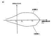
図4は、蓄電装置(たとえば図1の蓄電装置110)が充放電可能な電力と温度との関係を説明するためのグラフである。図4において、横軸は、蓄電池温度(℃)を、縦軸は、許容出力(kW)をそれぞれ示す。縦軸において、許容出力(kW)がプラスのとき、その値は蓄電装置のから取り出すことのできる電力(放電電力)を示す。これに対し、許容出力(kW)がマイナスのとき、その値は蓄電装置に入力することのできる電力(充電電力)を示す。
FIG. 4 is a graph for explaining the relationship between power and temperature that can be charged / discharged by the power storage device (for example,
図4を参照して、蓄電装置の温度がT2(あるいはT2に近い温度)以上かつT1(あるいはT1に近い温度)以下であれば、許容出力は比較的大きくなる。これに対し、蓄電装置の温度がT1(あるいはT1に近い温度)を超えるまたはT2(あるいはT2に近い温度)を下回ると、許容出力は制限される。また、蓄電装置の温度が高温、たとえばT1を上回る温度になると、蓄電装置が劣化するおそれもある。たとえば、蓄電装置110の温度がT1より大きいまたはT2より小さい場合、図3の制御部330は、(2)エンジン160のみによる外部給電動作、を優先させることができる。これにより、蓄電装置の使用頻度を制限し、蓄電装置の温度上昇を防ぐことができる。一方、蓄電装置110の温度がT2以上かつT1以下の場合、制御部330は、蓄電装置の使用を含めた外部給電動作を行ない得る。すなわち、制御部330は、(1)蓄電装置110のみによる外部給電動作、(2)エンジン160のみによる外部給電、または(3)蓄電装置110およびエンジン160による外部給電、から最適な効率の外部給電動作(効率最適モード)を選択することができる。これにより、外部給電の効率を向上させることができる。
Referring to FIG. 4, if the temperature of the power storage device is equal to or higher than T2 (or a temperature close to T2) and equal to or lower than T1 (or a temperature close to T1), the allowable output is relatively large. On the other hand, when the temperature of the power storage device exceeds T1 (or a temperature close to T1) or falls below T2 (or a temperature close to T2), the allowable output is limited. Further, when the temperature of the power storage device is high, for example, higher than T1, the power storage device may be deteriorated. For example, when the temperature of
さらに制御部330は、蓄電装置の温度がT2を下回る場合、図1に示す空調装置900を制御する。具体的に、制御部330は、空調装置900の暖房機能を始動させる。これにより、蓄電装置は暖機される。この暖機により蓄電装置の温度がT2以上になれば、蓄電装置の使用を含めた外部給電動作を行なうことが可能になる。
Further,
図5は、図1および図2の車両100から電気機器700への給電(外部給電)が行なわれるときに実行される制御を説明するためのフローチャートである。このフローチャートの処理は、図1などのECU300で実行される。
FIG. 5 is a flowchart for illustrating control executed when power supply (external power supply) is performed from
図1、図3〜図5を参照して、はじめに、車両100が外部給電モードに設定されているか否かが判断される(ステップS101)。車両100が外部給電モードに設定されている場合(ステップS101でYES)、ステップS102に処理が進められる。一方、車両100が外部給電モードに設定されていない場合(ステップS101でNO)、フローチャートは終了する。
With reference to FIGS. 1 and 3 to 5, first, it is determined whether or not
ステップS102において、蓄電装置の温度、たとえば図1の温度センサ800が測定する蓄電装置の外部の気温(外気温)が所定温度T1よりも小さいか否かが判断される。外気温が所定温度T1よりも小さい場合(ステップS102でYES)、ステップS104に処理が進められる。一方、外気温が所定温度T1以上の場合(ステップS102でNO)、ステップS103に処理が進められる。ステップS103において、エンジン160からの給電が優先されて、電気機器700に供給される。その後、ステップS101に再び処理が戻される。
In step S102, it is determined whether or not the temperature of the power storage device, for example, the temperature outside the power storage device (outside temperature) measured by
ステップS104では、外気温が所定温度T2よりも大きいか否かが判断される。ステップS104における所定温度T2は、蓄電装置の許容出力がある程度制限される温度である。所定温度T2は、所定温度T1よりも低い温度である。外気温が所定温度T2よりも大きい場合(ステップS104でYES)、ステップS106に処理が進められる。一方、外気温が所定温度T2以下の場合(ステップS104でNO)、ステップS105に処理が進められる。 In step S104, it is determined whether or not the outside air temperature is higher than a predetermined temperature T2. The predetermined temperature T2 in step S104 is a temperature at which the allowable output of the power storage device is limited to some extent. The predetermined temperature T2 is a temperature lower than the predetermined temperature T1. If the outside air temperature is higher than the predetermined temperature T2 (YES in step S104), the process proceeds to step S106. On the other hand, when the outside air temperature is equal to or lower than the predetermined temperature T2 (NO in step S104), the process proceeds to step S105.
ステップS105において、エンジン160からの給電が優先されるとともに、空調装置900の暖房機能が始動される。その後、ステップS101に再び処理が戻される。
In step S105, power supply from the
ステップS106において、効率最適モードで給電が行なわれる。なお、一旦ステップS105によって空調装置900の暖房機能が始動された後、このステップS106に処理が進められる場合もある。その場合、ステップS106においては、外気温が所定温度T2よりも大きいと判断されると、空調装置900の暖房機能が停止されるようにしてもよい。その後、ステップS101に再び処理が戻される。
In step S106, power is supplied in the optimum efficiency mode. Note that after the heating function of the
最後に、本発明の実施の形態について総括する。図1および図3を参照して、実施の形態に係るハイブリッド車両の制御装置(ECU300)は、内燃機関(エンジン160)と回転電機(モータジェネレータMG1,MG2)と蓄電装置110とが搭載され外部給電が可能なハイブリッド車両100に用いられる制御装置(ECU300)であって、蓄電装置110の温度に関連する情報を取得する温度情報取得部310と、蓄電装置110の温度が所定範囲を超える場合、蓄電装置110を充電せずに、内燃機関(エンジン160)により回転電機(モータジェネレータMG1,MG2)を駆動させて回転電機(モータジェネレータMG1,MG2)の発電電力をハイブリッド車両100の外部へ供給するようにハイブリッド車両100を制御し、蓄電装置110の温度が所定範囲を超えない場合、蓄電装置110の電力をハイブリッド車両100の外部へ供給するようにハイブリッド車両100を制御する制御部330とを備える。
Finally, embodiments of the present invention will be summarized. Referring to FIGS. 1 and 3, hybrid vehicle control apparatus (ECU 300) according to the embodiment includes an internal combustion engine (engine 160), rotating electrical machines (motor generators MG 1 and MG 2), and
好ましくは、所定範囲の上限温度は、上限温度より高い温度において蓄電装置が劣化するまたは蓄電装置の出力が制限される温度(T1)であり、所定範囲の下限温度は、下限温度より低い温度において蓄電装置の出力が制限される温度(T2)である。 Preferably, the upper limit temperature of the predetermined range is a temperature (T1) at which the power storage device deteriorates or the output of the power storage device is restricted at a temperature higher than the upper limit temperature, and the lower limit temperature of the predetermined range is a temperature lower than the lower limit temperature. This is the temperature (T2) at which the output of the power storage device is limited.
好ましくは、蓄電装置110の温度に関連する情報は、蓄電装置110の外部の気温である。
Preferably, the information related to the temperature of
好ましくは、ハイブリッド車両100には空調装置900がさらに搭載され、制御装置(ECU300)は、蓄電装置110の温度が所定範囲の下限温度(T2)よりも低い場合、空調装置900を制御する。
Preferably,
実施の形態に係るハイブリッド車両の制御装置によれば、蓄電装置の温度を考慮しつつ外部給電を行なうことが可能になる。 According to the hybrid vehicle control device of the embodiment, it is possible to perform external power feeding in consideration of the temperature of the power storage device.
今回開示された実施の形態は、すべての点で例示であって制限的なものではないと考えられるべきである。本発明の範囲は、上記した実施の形態の説明でなくて特許請求の範囲によって示され、特許請求の範囲と均等の意味および範囲内でのすべての変更が含まれることが意図される。 The embodiment disclosed this time should be considered as illustrative in all points and not restrictive. The scope of the present invention is shown not by the above description of the embodiment but by the scope of the claims, and is intended to include all modifications within the meaning and scope equivalent to the scope of the claims.
100 ハイブリッド車両、110 蓄電装置、121 コンバータ、122,123 インバータ、130,135 モータジェネレータ、140 動力伝達ギヤ、150 駆動輪、160 エンジン、170 通信部、175 アンテナ、200 電力変換装置、220 インレット、310 温度情報取得部、320 判断部、330 制御部、400 充電ケーブル、410 充電コネクタ、420 プラグ、440,ACL1,ACL2,PL1,PL2 電力線、500 外部電源、510 コンセント、600 給電コネクタ、610 出力部、620 電力伝達部、700 電気機器、710 電源プラグ、800 温度センサ、900 空調装置。
DESCRIPTION OF
Claims (4)
前記蓄電装置の温度に関連する情報を取得する温度情報取得部と、
前記蓄電装置の温度が所定範囲外の場合、前記蓄電装置を充電せずに、前記内燃機関により前記回転電機を駆動させて前記回転電機の発電電力を前記ハイブリッド車両の外部へ供給するように前記ハイブリッド車両を制御する制御部とを備え、
前記制御部は、前記蓄電装置の温度が前記所定範囲内の場合、前記蓄電装置のみによる第1の外部給電動作、前記内燃機関のみによる第2の外部給電動作、前記蓄電装置および前記内燃機関を併用する第3の外部給電動作のうちから最適な効率の外部給電動作を選択する、ハイブリッド車両の制御装置。 A control device used in a hybrid vehicle in which an internal combustion engine, a rotating electrical machine, and a power storage device are mounted and capable of external power feeding,
A temperature information acquisition unit for acquiring information related to the temperature of the power storage device;
When the temperature of the power storage device is outside a predetermined range, the rotating electrical machine is driven by the internal combustion engine to supply the generated electric power of the rotating electrical machine to the outside of the hybrid vehicle without charging the power storage device. A control unit for controlling the hybrid vehicle ,
When the temperature of the power storage device is within the predetermined range, the control unit controls a first external power supply operation only by the power storage device, a second external power supply operation only by the internal combustion engine, the power storage device and the internal combustion engine. A control device for a hybrid vehicle that selects an external power feeding operation having an optimum efficiency from among third power feeding operations to be used in combination .
前記所定範囲の下限温度は、前記下限温度より低い温度において前記蓄電装置の出力が制限される温度である、請求項1に記載のハイブリッド車両の制御装置。 The upper limit temperature of the predetermined range is a temperature at which the power storage device deteriorates or the output of the power storage device is limited at a temperature higher than the upper limit temperature,
2. The control device for a hybrid vehicle according to claim 1, wherein the lower limit temperature of the predetermined range is a temperature at which an output of the power storage device is limited at a temperature lower than the lower limit temperature.
前記制御装置は、前記蓄電装置の前記温度が前記所定範囲の下限温度よりも低い場合、前記空調装置を制御する、請求項1に記載のハイブリッド車両の制御装置。 The hybrid vehicle is further equipped with an air conditioner,
The control device for a hybrid vehicle according to claim 1, wherein the control device controls the air conditioner when the temperature of the power storage device is lower than a lower limit temperature of the predetermined range.
Priority Applications (2)
| Application Number | Priority Date | Filing Date | Title |
|---|---|---|---|
| JP2013196952A JP5884802B2 (en) | 2013-09-24 | 2013-09-24 | Control device for hybrid vehicle |
| PCT/IB2014/001893 WO2015044741A1 (en) | 2013-09-24 | 2014-09-22 | Control device and control method for hybrid vehicle, and hybrid vehicle |
Applications Claiming Priority (1)
| Application Number | Priority Date | Filing Date | Title |
|---|---|---|---|
| JP2013196952A JP5884802B2 (en) | 2013-09-24 | 2013-09-24 | Control device for hybrid vehicle |
Publications (2)
| Publication Number | Publication Date |
|---|---|
| JP2015063174A JP2015063174A (en) | 2015-04-09 |
| JP5884802B2 true JP5884802B2 (en) | 2016-03-15 |
Family
ID=51903948
Family Applications (1)
| Application Number | Title | Priority Date | Filing Date |
|---|---|---|---|
| JP2013196952A Active JP5884802B2 (en) | 2013-09-24 | 2013-09-24 | Control device for hybrid vehicle |
Country Status (2)
| Country | Link |
|---|---|
| JP (1) | JP5884802B2 (en) |
| WO (1) | WO2015044741A1 (en) |
Families Citing this family (3)
| Publication number | Priority date | Publication date | Assignee | Title |
|---|---|---|---|---|
| JP6146384B2 (en) | 2014-08-08 | 2017-06-14 | トヨタ自動車株式会社 | Hybrid vehicle |
| JP2020022301A (en) * | 2018-08-02 | 2020-02-06 | トヨタ自動車株式会社 | vehicle |
| JP7427454B2 (en) | 2020-01-21 | 2024-02-05 | 本田技研工業株式会社 | Battery temperature control device for electric vehicles |
Family Cites Families (12)
| Publication number | Priority date | Publication date | Assignee | Title |
|---|---|---|---|---|
| JP4337188B2 (en) * | 1999-06-25 | 2009-09-30 | トヨタ自動車株式会社 | Hybrid moving body and control method thereof |
| JP4775952B2 (en) | 2006-02-27 | 2011-09-21 | トヨタ自動車株式会社 | Building power supply system |
| JP4228086B1 (en) * | 2007-08-09 | 2009-02-25 | トヨタ自動車株式会社 | vehicle |
| JP5435920B2 (en) * | 2008-10-06 | 2014-03-05 | 富士通テン株式会社 | Electronic control device, plug-in vehicle, and power supply path switching method |
| JP4781425B2 (en) * | 2008-12-25 | 2011-09-28 | 本田技研工業株式会社 | Power supply system between vehicle and house |
| JP5446307B2 (en) * | 2009-02-17 | 2014-03-19 | 日産自動車株式会社 | Battery temperature control device, battery temperature control method, and automobile |
| US7973424B2 (en) * | 2009-04-03 | 2011-07-05 | General Electric Company | Method and apparatus for producing tractive effort with interface to other apparatus |
| CN103079897B (en) * | 2010-06-23 | 2015-03-25 | 丰田自动车株式会社 | Control device for vehicle and control method for vehicle |
| JP5758746B2 (en) | 2011-08-30 | 2015-08-05 | トヨタ自動車株式会社 | Power supply connector, vehicle, and vehicle control method |
| JP2013119347A (en) * | 2011-12-08 | 2013-06-17 | Mitsubishi Motors Corp | Hybrid electric vehicle |
| JP5716694B2 (en) * | 2012-03-01 | 2015-05-13 | トヨタ自動車株式会社 | Electric vehicle |
| JP6015038B2 (en) * | 2012-03-09 | 2016-10-26 | トヨタ自動車株式会社 | Vehicle and vehicle control method |
-
2013
- 2013-09-24 JP JP2013196952A patent/JP5884802B2/en active Active
-
2014
- 2014-09-22 WO PCT/IB2014/001893 patent/WO2015044741A1/en active Application Filing
Also Published As
| Publication number | Publication date |
|---|---|
| JP2015063174A (en) | 2015-04-09 |
| WO2015044741A1 (en) | 2015-04-02 |
Similar Documents
| Publication | Publication Date | Title |
|---|---|---|
| JP5660102B2 (en) | Vehicle power supply | |
| JP5343981B2 (en) | Vehicle charging system | |
| US8515605B2 (en) | On-vehicle equipment control system and vehicle | |
| JP5459408B2 (en) | Power supply system for electric vehicle, control method therefor, and electric vehicle | |
| JP5772781B2 (en) | Vehicle, power supply system, and control method for power supply system | |
| JP5321695B2 (en) | vehicle | |
| WO2014147781A1 (en) | Vehicle | |
| JP5661121B2 (en) | Vehicle and vehicle control method | |
| JP2018042370A (en) | Vehicle and method for controlling the same | |
| JP2014143817A (en) | Vehicular power system | |
| JP2008125163A (en) | Electric vehicle | |
| JP5278512B2 (en) | vehicle | |
| JP5630419B2 (en) | Power supply system and vehicle | |
| US9469210B2 (en) | Vehicle | |
| JP5783129B2 (en) | Electric vehicle | |
| JP2013192278A (en) | Electric vehicle | |
| JP2012249384A (en) | Vehicle | |
| JP2015077856A (en) | Hybrid-vehicular control apparatus | |
| JP5884802B2 (en) | Control device for hybrid vehicle | |
| JP2015057009A (en) | Vehicle | |
| WO2013042244A1 (en) | Vehicle power supply system | |
| JP6028643B2 (en) | Electric vehicle | |
| WO2012164681A1 (en) | Vehicle and method for controlling vehicle | |
| JP6003775B2 (en) | Power supply system, vehicle including the same, and control method of power supply system | |
| JP2014184881A (en) | Vehicle |
Legal Events
| Date | Code | Title | Description |
|---|---|---|---|
| A621 | Written request for application examination |
Free format text: JAPANESE INTERMEDIATE CODE: A621 Effective date: 20150204 |
|
| A977 | Report on retrieval |
Free format text: JAPANESE INTERMEDIATE CODE: A971007 Effective date: 20150723 |
|
| A131 | Notification of reasons for refusal |
Free format text: JAPANESE INTERMEDIATE CODE: A131 Effective date: 20150728 |
|
| A521 | Request for written amendment filed |
Free format text: JAPANESE INTERMEDIATE CODE: A523 Effective date: 20150907 |
|
| TRDD | Decision of grant or rejection written | ||
| A01 | Written decision to grant a patent or to grant a registration (utility model) |
Free format text: JAPANESE INTERMEDIATE CODE: A01 Effective date: 20160112 |
|
| A61 | First payment of annual fees (during grant procedure) |
Free format text: JAPANESE INTERMEDIATE CODE: A61 Effective date: 20160125 |
|
| R151 | Written notification of patent or utility model registration |
Ref document number: 5884802 Country of ref document: JP Free format text: JAPANESE INTERMEDIATE CODE: R151 |