JP5884682B2 - Air conditioner for vehicles - Google Patents
Air conditioner for vehicles Download PDFInfo
- Publication number
- JP5884682B2 JP5884682B2 JP2012189583A JP2012189583A JP5884682B2 JP 5884682 B2 JP5884682 B2 JP 5884682B2 JP 2012189583 A JP2012189583 A JP 2012189583A JP 2012189583 A JP2012189583 A JP 2012189583A JP 5884682 B2 JP5884682 B2 JP 5884682B2
- Authority
- JP
- Japan
- Prior art keywords
- air
- temperature
- reference value
- sensor
- outside air
- Prior art date
- Legal status (The legal status is an assumption and is not a legal conclusion. Google has not performed a legal analysis and makes no representation as to the accuracy of the status listed.)
- Expired - Fee Related
Links
Images


Landscapes
- Air-Conditioning For Vehicles (AREA)
Description
本発明は、車両用空調装置に関するものである。 The present invention relates to a vehicle air conditioner.
従来、外気(車室外空気)の汚れに応じて内外気モードを自動的に切り替える車両用空調装置がある。この空調装置は、車室外に設けられた排ガスセンサによって外気の汚染度を検出し、排ガスセンサの検出結果が判定基準値より大きいときに、外気のみを空調ケース内に導入する外気導入モードから内気(車室内空気)のみを空調ケース内に導入する内気循環モードに切り替えている(例えば、特許文献1等参照)。 2. Description of the Related Art Conventionally, there is a vehicle air conditioner that automatically switches the inside / outside air mode according to the dirt of outside air (air outside the passenger compartment). This air conditioner detects the degree of contamination of the outside air by an exhaust gas sensor provided outside the passenger compartment, and when the detection result of the exhaust gas sensor is larger than a criterion value, the outside air is introduced from the outside air introduction mode in which only the outside air is introduced into the air conditioning case. The mode is switched to an inside air circulation mode in which only (vehicle interior air) is introduced into the air conditioning case (see, for example, Patent Document 1).
ここで、この判定基準値が全ての車両で同じ場合、外気の汚れ度合いに対する乗員の感覚に個人差があるため、乗員によっては、外気導入モード(以下、外気モードという)から内気循環モード(以下、内気モードという)への切り替わりが遅く、汚れた外気が車室内に導入されることによって乗員が不快に感じてしまう。 Here, when this criterion value is the same for all vehicles, there is an individual difference in the sense of the occupant with respect to the degree of dirtiness of the outside air. Switching to the inside air mode) is slow, and dirty outside air is introduced into the passenger compartment, which makes the passenger feel uncomfortable.
そこで、特許文献1に記載の車両用空調装置では、判定基準値を乗員が手動で変更可能な構成としている。これによれば、乗員が自分の感覚に応じて判定基準値を変更することができるので、汚れた外気にて乗員に不快感を与えないようにすることができる。
Therefore, the vehicle air conditioner described in
ところで、近年の車両における空調制御では、空調ケース内に内気を優先的に導入する内気化が進んでいる。このため、車室内に持ち込んだ食べ物や乗員が吐く息等によって、内気が汚染しやすくなる。 By the way, in recent air-conditioning control in a vehicle, inside air is preferentially introduced into the air-conditioning case with inside air preferentially. For this reason, the inside air tends to be contaminated by food brought into the passenger compartment or breath exhaled by the passenger.
そこで、この対策として、空気の汚染度を検出するための空気質センサを車室内に設け、内外気モードが内気モードのときに、空気質センサの検出結果と判定基準値とを比較し、この出力結果が判定基準値を超え、内気が汚染していると判断された場合に、内気モードを外気モードに自動的に切り替えるようにすることが考えられる。 Therefore, as a countermeasure, an air quality sensor for detecting the degree of air pollution is provided in the vehicle interior, and when the inside / outside air mode is the inside air mode, the detection result of the air quality sensor is compared with the determination reference value. When the output result exceeds the determination reference value and it is determined that the inside air is contaminated, the inside air mode may be automatically switched to the outside air mode.
しかし、車室内は、冬季のウォームアップ時や夏季のクールダウン時のように、車室内は温度が急変する環境である。冬季では、空調開始直後の低温(例えば−30℃〜0℃)から設定温度(常温)に向かって連続して上昇し続け(ウォームアップ)、夏季では、空調開始直後の高温(例えば80℃)から設定温度(常温)に向かって連続して下降し続ける(クールダウン)。外気も夜と昼のように一日にわたって温度が変動するが、このように内気の方が外気よりも短時間で大きく温度が変動する。 However, the interior of the passenger compartment is an environment in which the temperature of the passenger compartment changes abruptly, such as during warm-up in winter and cool-down in summer. In winter, it continues to rise (warm-up) from a low temperature (for example, −30 ° C. to 0 ° C.) immediately after the start of air conditioning to a set temperature (room temperature), and in summer, a high temperature (for example, 80 ° C.) immediately after the start of air conditioning. Continue to descend from the temperature to the set temperature (room temperature) (cool down). The temperature of the outside air also fluctuates over the whole day like night and noon, but the temperature of the inside air fluctuates more greatly in a shorter time than the outside air.
また、一般的な空気質センサは、センサ近傍温度に応じて応答性能が変わる性質(温度特性)を有している。 Further, a general air quality sensor has a property (temperature characteristic) in which response performance changes according to the temperature near the sensor.
このため、判定基準値が常に一定の場合、図9に示すように、空気質センサの検出結果が判定基準値までに到達する到達時間が、センサ近傍温度である車室内温度によって異なってしまう。この結果、内気モードから外気モードへの切り替わりのタイミングが車室内温度によって異なり、乗員が不快に感じてしまう。 For this reason, when the determination reference value is always constant, as shown in FIG. 9, the arrival time for the detection result of the air quality sensor to reach the determination reference value varies depending on the vehicle interior temperature, which is the sensor vicinity temperature. As a result, the timing of switching from the inside air mode to the outside air mode differs depending on the passenger compartment temperature, and the passenger feels uncomfortable.
例えば、ウォームアップ時では、車室内温度が低温なので、車室内温度が常温の場合と比較して、内気モードから外気モードへの切り替わりが遅れる。この場合、内気の汚染により乗員が不快に感じる。 For example, at the time of warm-up, the temperature in the passenger compartment is low, so that the switching from the inside air mode to the outside air mode is delayed compared to the case where the passenger compartment temperature is normal temperature. In this case, the passenger feels uncomfortable due to the contamination of the inside air.
クールダウン時では、車室内温度が高温なので、車室内温度が常温の場合と比較して、内気モードから外気モードへの切り替わりが早くなる。この場合、乗員が音などで内外気モードの切り替わりを感じたときに、内気が汚れていないのに外気モードに切り替わることで、乗員が不快に感じる。なお、この場合、内気が比較的汚れていない状態でも、外気モードへ切り替わるため、内外気モードの切り替わりの頻度が増加し、内外気切換ドアが頻繁に作動するため、内外気切換ドアのアクチュエータの寿命が短くなるという問題も生じる。 At the time of cool-down, since the vehicle interior temperature is high, the switching from the inside air mode to the outside air mode is faster than when the vehicle interior temperature is normal temperature. In this case, when the occupant feels switching between the inside and outside air modes with sound or the like, the occupant feels uncomfortable by switching to the outside air mode even though the inside air is not dirty. In this case, even when the inside air is not relatively dirty, since the mode is switched to the outside air mode, the frequency of switching between the inside and outside air modes is increased and the inside / outside air switching door is frequently operated. There is also a problem that the lifetime is shortened.
そこで、この対策として、特許文献1に記載の車両用空調装置のように、判定基準値までの到達時間が一定となるように、判定基準値を乗員によって手動で変更可能とすることが考えられる。
Therefore, as a countermeasure, it is conceivable that the determination reference value can be manually changed by the occupant so that the arrival time to the determination reference value is constant as in the vehicle air conditioner described in
外気の汚れに応じて内外気モードを自動的に切り替える場合であって、外気温に応じて判定基準値を乗員が手動で変更する場合であれば、外気温は急変しないので、朝、昼、夜等の数回だけ、判定基準値を乗員が手動で変更すれば良い。 If the inside / outside air mode is automatically switched according to the dirt of the outside air and the occupant manually changes the judgment reference value according to the outside air temperature, the outside air temperature does not change suddenly. The occupant only has to manually change the judgment reference value several times such as at night.
しかし、内気の汚れに応じて内外気モードを自動的に切り替える場合であって、車室内温度に応じて判定基準値を乗員が手動で変更する場合、ウォームアップやクールダウン時では、車室内温度が設定温度に向かって連続して変動するため、空調開始時から車室内温度が安定するまでの期間、判定基準値を頻繁に変更しなければならず、乗員の手間がかかるという問題が生じる。また、判定基準値を変更するために、運転中に乗員が頻繁に操作することは安全面上好ましくない。 However, when the inside / outside air mode is automatically switched according to the dirt of the inside air, and the occupant manually changes the judgment reference value according to the inside temperature of the passenger compartment, the vehicle interior temperature during warm-up or cool-down Therefore, the determination reference value must be frequently changed during the period from the start of air conditioning to the stabilization of the passenger compartment temperature, which causes a problem that it takes time for the passenger. In addition, it is not preferable in terms of safety that an occupant frequently operates during driving in order to change the determination reference value.
なお、上記した問題は、内気モードと外気モードとを自動的に切り替える場合に限らず、内外気混入モードで内気と外気との導入割合を自動的に変更する車両用空調装置においても、同様に発生するものである。 The problem described above is not limited to the case of automatically switching between the inside air mode and the outside air mode, but also in the vehicle air conditioner that automatically changes the introduction ratio of the inside air and the outside air in the inside / outside air mixing mode. It is what happens.
本発明は上記点に鑑みて、乗員が判定基準値を変更しなくても、内気と外気との導入割合の自動的な変更を適切に行うことができる車両用空調装置を提供することを目的とする。 The present invention has been made in view of the above points, and an object of the present invention is to provide a vehicle air conditioner that can automatically change the introduction ratio between the inside air and the outside air without the occupant changing the determination reference value. And
上記目的を達成するため、請求項1に記載の発明では、
内気と外気とを所定の割合にて内部に導入し、車室内に向かって空調風を吹き出す空調ケース(11)と、
空調ケースに設けられ、空調ケース内に導入される内気と外気の割合を変更する導入割合変更手段(12)と、
内気の汚染度を検出するための空気質センサ(44)と、
空調ケース内に内気が導入されているときに、空気質センサの出力に基づく検出結果(Ln)が判定基準値(Ls)を超える場合に、外気の導入割合を増大させるように、導入割合変更手段の作動を制御する制御装置(30)と、
空気質センサの近傍温度を検出する温度センサ(39)とを備え、
制御装置は、空調開始直後の設定温度に向かって車室内温度を上昇させ続けるウォームアップ時または空調開始直後の設定温度に向かって車室内温度を下降させ続けるクールダウン時において、温度センサの検出温度が変化したとき、温度センサの検出温度が低いほど、内気が汚染した場合に検出結果が判定基準値に到達するまでの時間を短縮させる方向に、判定基準値を変更することを特徴とする。
In order to achieve the above object, in the invention described in
An air conditioning case (11) for introducing inside air and outside air into the interior at a predetermined ratio and blowing out conditioned air toward the vehicle interior;
An introduction ratio changing means (12) provided in the air conditioning case for changing the ratio of the inside air and the outside air introduced into the air conditioning case;
An air quality sensor (44) for detecting the degree of contamination of inside air;
When the inside air is introduced into the air conditioning case, if the detection result (Ln) based on the output of the air quality sensor exceeds the criterion value (Ls), the introduction rate is changed to increase the outside air introduction rate. A control device (30) for controlling the operation of the means;
A temperature sensor (39) for detecting the temperature in the vicinity of the air quality sensor,
The control device detects the temperature detected by the temperature sensor at the time of warm-up that continues to increase the vehicle interior temperature toward the set temperature immediately after the start of air conditioning or at the time of cool-down that continues to decrease the vehicle interior temperature toward the set temperature immediately after the start of air conditioning. When the temperature changes, the lower the detection temperature of the temperature sensor, the more the determination reference value is changed in a direction to shorten the time until the detection result reaches the determination reference value when the inside air is contaminated.
本発明では、空気質センサの近傍温度が変化したときに、空気質センサの近傍温度が低いほど、内気が汚染した場合に空気質センサの検出結果が判定基準値に到達するまでの到達時間を短縮させる方向に、判定基準値を変更するので、判定基準値が常に一定の場合と比較して、車室内温度による到達時間の差を縮めることができる。 In the present invention, when the temperature near the air quality sensor changes, the lower the temperature near the air quality sensor, the longer the arrival time until the detection result of the air quality sensor reaches the determination reference value when the inside air is contaminated. Since the determination reference value is changed in the direction of shortening, the difference in arrival time due to the passenger compartment temperature can be reduced as compared with the case where the determination reference value is always constant.
これにより、本発明によれば、乗員が判定基準値を変更しなくても、内気と外気との導入割合の自動的な変更を適切に行うことができる。 Thereby, according to this invention, even if a passenger | crew does not change a determination reference value, the automatic change of the introduction ratio of inside air and outside air can be performed appropriately.
なお、この欄および特許請求の範囲で記載した各手段の括弧内の符号は、後述する実施形態に記載の具体的手段との対応関係を示す一例である。 In addition, the code | symbol in the bracket | parenthesis of each means described in this column and the claim is an example which shows a corresponding relationship with the specific means as described in embodiment mentioned later.
以下、本発明の実施形態について図に基づいて説明する。なお、以下の各実施形態相互において、互いに同一もしくは均等である部分には、同一符号を付して説明を行う。 Hereinafter, embodiments of the present invention will be described with reference to the drawings. In the following embodiments, parts that are the same or equivalent to each other will be described with the same reference numerals.
(第1実施形態)
車両用空調装置は、室内空調ユニット10と空調制御装置30とを備えている。室内空調ユニット10は、車室内最前部の計器盤(インストルメントパネル)の内側に配置されて、その外殻を形成する空調ケース11内に送風機、蒸発器、凝縮器、ヒータコア等を収容したものである。
(First embodiment)
The vehicle air conditioner includes an indoor
空調ケース11は、車室内に送風される空気の通路を形成しており、内気と外気とを所定の割合にて内部に導入した後、車室内に向かって空調風を吹き出す。空調ケース11内の空気流れ最上流側には、内気と外気とを切替導入する内外気切替箱111が配置されている。
The air conditioning case 11 forms a passage for air to be blown into the vehicle interior, and after introducing inside air and outside air at a predetermined ratio, blows air-conditioned air toward the vehicle interior. On the most upstream side of the air flow in the air conditioning case 11, an inside / outside
内外気切替箱111には、空調ケース11内に内気を導入させる内気導入口112および外気を導入させる外気導入口113が形成されている。さらに、内外気切替箱111の内部には、サーボモータ等の電動アクチュエータ12aによって駆動され、内外気モードを切り替える内外気切替ドア12が配置されている。内外気切替ドア12は、内気導入口112および外気導入口113の開口面積を調整して、内気の風量と外気の風量との風量割合を変更するものである。したがって、内外気切替ドア12は、空調ケース11内に導入される内気と外気の割合を変更する導入割合変更手段を構成する。
The inside / outside
本実施形態では、内外気モードとして、内気導入口112を全開とするとともに外気導入口113を全閉として空調ケース11内へ内気のみを導入する内気モードと、内気導入口112を全閉とするとともに外気導入口113を全開として空調ケース11内へ外気のみを導入する外気モードとが切り替えられる。したがって、本実施形態では、内気と外気の導入割合を、内気と外気のいずれか一方が0%となるように変更している。また、内気モードから外気モードへ切り替わった場合、外気の導入割合が0%から100%に増大することとなる。
In the present embodiment, as the inside / outside air mode, the inside
内外気切替箱111の空気流れ下流側には、内外気モードに応じた所定割合の内気と外気とを吸入し、吸入した空気を車室内へ向けて送風する送風機13が配置されている。送風機は、遠心多翼ファン13aを電動モータ13bにて駆動する電動送風機である。
On the downstream side of the air flow in the inside / outside
送風機の空気流れ下流側には、蒸発器14が配置されている。蒸発器14は冷却用熱交換器であって、図示しない圧縮機等と結合されて冷凍サイクルを構成し、その内部の低圧冷媒が空気から吸熱して蒸発することにより空気を冷却する。
An
さらに、蒸発器14の空気流れ下流側には、ヒータコア15が配置されている。ヒータコア15は加熱用熱交換器であって、図示しない車両エンジンの冷却水(温水)が内部を循環し、このエンジン冷却水を熱源として空気を加熱する。
Further, a
ヒータコア15の上流側には、吹出空気温度調整手段としてのエアミックスドア16が設けられている。エアミックスドア16の開度は電動アクチュエータ16aにより駆動されて調節される。これによって、ヒータコア15を通過する空気とヒータコア15をバイパスする空気の割合とが調整され、車室内に吹き出す空気の温度が調整される。
On the upstream side of the
空調ケースの最下流には、デフロスタ(DEF)吹出口17を開閉するデフロスタドア18、フェイス(FACE)吹出口19を開閉するフェイスドア20、およびフット(FOOT)吹出口21を開閉するフットドア22が設けられている。
At the most downstream of the air conditioning case, there are a
これら各ドア18、20、22は吹出モード切替手段を構成するもので、アクチュエータ23により駆動されて各吹出口17、19,21を開閉することによって各種の吹出モード(フェイスモード、バイレベルモード、フットモード、フットデフモード、デフロスタモード等)が設定される。そして、各吹出モードに応じて開口した吹出口から、温度調整された空気が車室内へ吹き出される。
These
空調制御装置30は、CPU、ROMおよびRAM等を含む周知のマイクロコンピュータ31とその周辺回路から構成され、そのROM内に記憶された空調制御プログラムに基づいて各種演算、処理を行い、駆動回路32を介して、出力側に接続された内外気切替ドア12用の電動アクチュエータ12aの作動を制御する。なお、送風機13の電動モータ13b、他の電動アクチュエータ16a、23も、マイクロコンピュータ31からの出力信号に基づいて駆動回路32にて制御される。
The air
マイクロコンピュータ31には、車室内計器盤に設置された空調操作部(空調操作パネル)33から操作信号が入力される。この空調操作部33には、空調装置の自動制御状態を設定するAUTOスイッチ34、内外気モードを手動で切替設定するための内外気切替スイッチ35、吹出モードを手動で切替設定するための吹出モード切替スイッチ36、ファン23の送風量を手動で切替設定するための送風量切替スイッチ37、乗員の好みの車室内温度を設定するための温度設定スイッチ38等が設けられている。
An operation signal is input to the
また、マイクロコンピュータ31には、車室内の空調状態に影響を及ぼす環境条件を検出する信号として、内気温度TRを検出する内気温センサ39、外気温度TAMを検出する外気温センサ40、車室内に入射する日射量TSを検出する日射センサ41、蒸発器温度TEを検出する蒸発器温度センサ42、ヒータコア15を循環するエンジン水温TWを検出する水温センサ43等からの各信号が入力される。
Further, the
さらに、マイクロコンピュータ31には、内気の汚染度を検出するための空気質センサ(ガスセンサ)44からの出力信号が入力される。空気質センサ44は、内気の汚染度として、空気中の飲食物の臭いやCO2等の検出対象ガスの濃度変化(汚染度)を検出する。空気質センサ44は、図2に示すように、インストルメントパネルのうち内気温センサ39の隣りに設けられる。このため、内気温センサ39によって空気質センサ44の近傍温度が検出される。
Further, the
空気質センサ44としては、例えば、金属酸化物半導体(SiO2、SnO2等)からなるセンサ素子(図示せず)と、センサ素子の表面を加熱する電気ヒータ(図示せず)とを備え、センサ素子表面での検出対象ガスの酸化・還元反応によってセンサ素子の抵抗値が変化する現象を利用したものが採用される。センサ素子表面の周囲温度が空気質センサ44の近傍温度である。半導体素子が金属酸化物半導体からなり、電気ヒータを用いる空気質センサは、上述の通り、温度特性を有している。なお、電気ヒータの加熱温度は検出対象ガスによって異なる。
As the
空調制御装置30は、図3に示すように、空気質センサ44の出力に基づく検出結果に応じて、内外気の導入割合を決定し、内外気切替ドア12の作動を制御する。この制御は、AUTOスイッチ34がオンの状態のときに実行される。また、AUTOスイッチ34がオンの状態に初めてなったときでは、内気モードが自動的に選択され、タイマーが初期化され、空気質センサ44の電気ヒータが通電される。なお、図3中の各ステップの機能は、空調制御装置30が有する各機能手段に相当する。
As shown in FIG. 3, the air
まず、ステップS10では、空気質センサ44がウォームアップ中であるか否かを判定する。具体的には、空気質センサ44の電気ヒータの通電開始からの経過時間が所定時間よりも短いか否かを判定する。所定時間とは、ヒータ温度が安定するまでの時間である。この判定をするのは、電気ヒータの温度が安定するまでの時間、空気質センサ44の出力値を使用しないようにするためである。所定時間を経過するまで、このステップS10が繰り返され、所定時間を経過して空気質センサ44のウォームアップが終了すると、ステップS20に進む。
First, in step S10, it is determined whether or not the
ステップS20では、ステップS30での初期設定のために、センサ近傍温度(Tsen)を内気温センサ39の出力信号から取得する。
In step S20, the sensor vicinity temperature (Tsen) is acquired from the output signal of the internal
ステップS30では、判定基準値および前回のセンサ近傍温度(Tsen_old)の初期設定を行う。判定基準値(Ls)については、ROM等の記憶手段に予め記憶されている図4に示すマップを用いて、ステップS20で取得したセンサ近傍温度(Tsen)に応じた判定基準値(Ls)を初期値としてセットする。また、前回のセンサ近傍温度(Tsen_old)については、ステップS20で取得したセンサ近傍温度(Tsen)を初期値としてセットする。 In step S30, initial setting of the determination reference value and the previous sensor vicinity temperature (Tsen_old) is performed. For the determination reference value (Ls), the determination reference value (Ls) corresponding to the sensor vicinity temperature (Tsen) acquired in step S20 is used using the map shown in FIG. 4 stored in advance in storage means such as a ROM. Set as initial value. For the previous sensor vicinity temperature (Tsen_old), the sensor vicinity temperature (Tsen) acquired in step S20 is set as an initial value.
続いて、ステップS40では、ガス濃度基準値(Rair)を設定する。ガス濃度基準値は、後述するガス濃度変化率(Ln)を算出する上での基準値である。ガス濃度基準値(Rair)の設定方法としては、種々の方法があるが、本実施形態では、乗員が乗車したときの車室内のガス濃度における半導体素子の抵抗値をガス濃度基準値とする。具体的には、空気質センサ44のウォームアップ直後における空気質センサ44の出力電圧からセンサ素子の抵抗値を算出する。
Subsequently, in step S40, a gas concentration reference value (Rair) is set. The gas concentration reference value is a reference value for calculating a gas concentration change rate (Ln) described later. There are various methods for setting the gas concentration reference value (Rair). In this embodiment, the resistance value of the semiconductor element at the gas concentration in the passenger compartment when the occupant gets in the vehicle is used as the gas concentration reference value. Specifically, the resistance value of the sensor element is calculated from the output voltage of the
続いて、ステップS50では、空気質センサ44の出力電圧から現在のガス濃度におけるセンサ素子の抵抗値(Rgas)を算出する。
Subsequently, in step S50, the resistance value (Rgas) of the sensor element at the current gas concentration is calculated from the output voltage of the
続いて、ステップS60では、ガス濃度変化率(Ln)を算出する。ガス濃度変化率(Ln)は、下記式の通り、ガス濃度基準値(Rair)から現在のガス濃度における抵抗値(Rgas)が変化した割合を示す。 Subsequently, in step S60, a gas concentration change rate (Ln) is calculated. The gas concentration change rate (Ln) indicates the rate at which the resistance value (Rgas) at the current gas concentration has changed from the gas concentration reference value (Rair) as shown in the following equation.
Ln=Rgas/Rair
続いて、ステップS70では、センサ近傍温度(Tsen)を内気温センサ39の出力信号から取得する。
Ln = Rgas / Rair
Subsequently, in step S70, the sensor vicinity temperature (Tsen) is acquired from the output signal of the inside
続いて、ステップS80では、ステップS70で取得した今回のセンサ近傍温度(Tsen)と前回のセンサ近傍温度(Tsen_old)を比較し、センサ近傍温度が変化したか否かを判定する。温度差が所定値よりも小さい場合、センサ近傍温度は変化無しと判定して、ステップS110に進む。一方、温度差が所定値よりも大きい場合、センサ近傍温度が変化したと判定して、ステップS90に進む。 Subsequently, in step S80, the current sensor vicinity temperature (Tsen) acquired in step S70 is compared with the previous sensor vicinity temperature (Tsen_old) to determine whether the sensor vicinity temperature has changed. If the temperature difference is smaller than the predetermined value, it is determined that the sensor vicinity temperature has not changed, and the process proceeds to step S110. On the other hand, when the temperature difference is larger than the predetermined value, it is determined that the sensor vicinity temperature has changed, and the process proceeds to step S90.
ステップS90では、判定基準値(Ls)を、ステップS70で取得した今回のセンサ近傍温度(Tsen)に応じた判定基準値(Ls)に変更する。具体的には、図4に示すマップを用いて、ステップS70で取得した今回のセンサ近傍温度(Tsen)に応じた判定基準値(Ls)を求め、この判定基準値(Ls)を新しい判定基準値(Ls)に設定する。図4に示すマップは、センサ近傍温度が低いほど、判定基準値が小さくなるように、判定基準値を変更するものである。すなわち、センサ近傍温度によらず、ガス濃度変化率(Ln)が判定基準値に到達するまでの到達時間が一定となるように、判定基準値を変更するものである。 In step S90, the determination reference value (Ls) is changed to the determination reference value (Ls) corresponding to the current sensor vicinity temperature (Tsen) acquired in step S70. Specifically, a determination reference value (Ls) corresponding to the current sensor vicinity temperature (Tsen) acquired in step S70 is obtained using the map shown in FIG. 4, and this determination reference value (Ls) is used as a new determination reference. Set to the value (Ls). The map shown in FIG. 4 changes the determination reference value so that the determination reference value decreases as the sensor vicinity temperature decreases. That is, the determination reference value is changed so that the arrival time until the gas concentration change rate (Ln) reaches the determination reference value is constant regardless of the sensor vicinity temperature.
続いて、ステップS100では、ステップS70で取得したセンサ近傍温度(Tsen)を、前回のセンサ近傍温度(Tsen_old)へ設定する(Tsen_old=Tsen)。 Subsequently, in step S100, the sensor vicinity temperature (Tsen) acquired in step S70 is set to the previous sensor vicinity temperature (Tsen_old) (Tsen_old = Tsen).
ステップS110では、内外気判定処理を行う。すなわち、ガス濃度変化率(Ln)と判定基準値(Ls)を比較し、内外気モードの制御判定値(DL)を算出する。 In step S110, inside / outside air determination processing is performed. That is, the control determination value (DL) in the inside / outside air mode is calculated by comparing the gas concentration change rate (Ln) and the determination reference value (Ls).
ここで、ガス濃度が低濃度から高濃度へ変化したときに、空気質センサ44の出力電圧から算出した抵抗値(Rgas)が増大する場合、ガス濃度変化率(Ln)も増大する。この場合、ガス濃度変化率(Ln)が判定基準値(Ls)よりも大きいとき、車室内空間はガス濃度が高く、換気が必要な状態であるので、外気モードを選択する。一方、ガス濃度変化率(Ln)が判定基準値(Ls)よりも小さいとき、車室内空間は換気が必要なほどガス濃度が高くないので、内気モードを選択する。
Here, if the resistance value (Rgas) calculated from the output voltage of the
ステップS120では、内外気モードの制御判定値(DL)に応じて、内外気切換ドア13の作動制御信号を出力する。その後、ステップS50に戻る。 In step S120, an operation control signal for the inside / outside air switching door 13 is output according to the control judgment value (DL) in the inside / outside air mode. Thereafter, the process returns to step S50.
内外気モードが内気モードのときに、ステップS110で、内気モードが選択された場合、ステップS120では、内外気切換ドア13の位置は変更されず、再び、ステップS50〜ステップS110が実行される。 When the inside / outside air mode is the inside air mode, if the inside air mode is selected in step S110, the position of the inside / outside air switching door 13 is not changed in step S120, and steps S50 to S110 are executed again.
この制御によれば、車室内空間のガス濃度が高濃度になるまでは、ステップS50〜ステップS120が繰り返し実行される。 According to this control, steps S50 to S120 are repeatedly executed until the gas concentration in the vehicle interior space becomes high.
そして、車室内空間のガス濃度が高濃度になると、ステップS110、S120により、内外気切換ドア13が外気モードの位置となり、車室内空間に外気が導入されて換気される。 When the gas concentration in the vehicle interior space becomes high, the inside / outside air switching door 13 is set to the outside air mode position in steps S110 and S120, and the outside air is introduced into the vehicle interior space for ventilation.
その後、外気モードの状態で、ステップS50〜ステップS120が繰り返し実行される。車室内空間の換気が進み、ガス濃度が高濃度から低濃度になると、ステップS110、S120により、再び、内気モードとなる。 Thereafter, Step S50 to Step S120 are repeatedly executed in the outside air mode. When ventilation of the vehicle interior space progresses and the gas concentration changes from high to low, the inside air mode is set again through steps S110 and S120.
次に、本実施形態の効果を説明する。 Next, the effect of this embodiment will be described.
まず、比較例1として、判定基準値が自動変更されず、判定基準値が一定の場合について説明する。比較例1は、判定基準値が自動変更されないこと以外は、本実施形態と同じである。以下では、冬季のウォームアップ時を例に説明する。 First, as Comparative Example 1, a case where the determination reference value is not automatically changed and the determination reference value is constant will be described. Comparative Example 1 is the same as the present embodiment except that the determination reference value is not automatically changed. In the following description, the warm-up in winter will be described as an example.
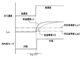
図5に示すように、ガス濃度が低濃度から高濃度へ変化した際、変化直後からの経過時間を横軸とし、ガス濃度変化率(Ln)を縦軸としたときに、ガス濃度変化率(Ln)が描く曲線は、空気質センサ44が設置された環境の温度(センサ近傍温度)によって異なる。具体的には、低温環境では、常温環境よりもガス濃度変化率(Ln)の傾きが小さい。このように、環境温度が高いほど、ガス濃度変化率(Ln)の傾きが大きくなり、温度が低いほど、ガス濃度変化率(Ln)の傾きが小さくなる。このため、判定基準値(Ls)が一定の場合、ガス濃度変化率(Ln)が判定基準値に到達するまでの時間は、環境温度が低いほど長くなり、環境温度が低いほど内気モードから外気モードへの切り替わりが遅くなる(図9参照)。
As shown in FIG. 5, when the gas concentration changes from a low concentration to a high concentration, the elapsed time from immediately after the change is plotted on the horizontal axis, and the gas concentration change rate (Ln) is plotted on the vertical axis. The curve drawn by (Ln) varies depending on the temperature of the environment where the
したがって、冬季のウォームアップ時の車室内温度は低温であり、ウォームアップ後の車室内温度は設定温度付近の常温であるので、ウォームアップ時では、ウォームアップ後と比較して、内気モードから外気モードへの切り替わりに(T2−T1)時間の遅れが生じてしまう。 Therefore, the vehicle interior temperature during warm-up in winter is low, and the vehicle interior temperature after warm-up is a room temperature around the set temperature. There is a time delay in switching to the mode (T2-T1).
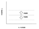
また、比較例2として、乗員操作による判定基準値の変更が可能であって、図6に示すように、ウォームアップ時に乗員が手動によって判定基準値を変更する場合を説明する。この場合、車室内温度は、設定温度に近づくように温度が上昇し続けるため、乗員が頻繁に変更操作をしなければならない。したがって、乗員が判定基準値を変更することは、乗員の手間がかかるとともに、安全面上に問題があることから好ましくない。 Further, as Comparative Example 2, a case will be described in which the determination reference value can be changed by an occupant operation and the occupant manually changes the determination reference value during warm-up as shown in FIG. In this case, the passenger compartment temperature must be changed frequently because the vehicle interior temperature continues to rise so as to approach the set temperature. Therefore, it is not preferable for the occupant to change the determination reference value because it takes time and effort for the occupant and there are problems in terms of safety.
これに対して、本実施形態では、ステップS80、S90での説明の通り、図4のマップを用いて、センサ近傍温度に応じて判定基準値を自動的に変更している。 On the other hand, in this embodiment, as described in steps S80 and S90, the determination reference value is automatically changed according to the sensor vicinity temperature using the map of FIG.
ここで、図4に示すマップは、同じガス濃度条件でガス濃度が低濃度から高濃度へ変わる際に、センサ近傍温度によらず、ガス濃度変化率(Ln)が判定基準値に到達するまでの到達時間が一定となるように作成されたものである。このようなマップは、実験およびシミュレーション等により作成される。 Here, the map shown in FIG. 4 shows that when the gas concentration changes from a low concentration to a high concentration under the same gas concentration conditions, the gas concentration change rate (Ln) reaches the determination reference value regardless of the sensor vicinity temperature. It was created so that the arrival time of was constant. Such a map is created by experiments and simulations.
これにより、図7に示すように、ガス濃度が低濃度から高濃度へ変化した際、ウォームアップ時(低温環境)とウォームアップ後(常温環境)のどちらも、内気モードから外気モードへの切り替わりの時間を同じT1とすることができる。 As a result, as shown in FIG. 7, when the gas concentration is changed from a low concentration to a high concentration, switching from the inside air mode to the outside air mode is performed both during warm-up (low temperature environment) and after warm-up (room temperature environment). Can be set to the same T1.
また、ウォームアップ時の温度が変動し続ける場合でも、内気モードから外気モードへの切り替わりの時間が同じT1となるように、センサ近傍温度に応じて判定基準値を自動的に変更するので、乗員に不快感を与えずに、内気モードと外気モードとの自動的な切り替えを適切に行うことができる。さらに、乗員による判定基準値の変更操作が不要なので、乗員の手間がかからず、安全面でもうれしさがある。 Further, even when the temperature at the time of warm-up continues to fluctuate, the determination reference value is automatically changed according to the sensor vicinity temperature so that the switching time from the inside air mode to the outside air mode becomes the same T1, so that the occupant Thus, automatic switching between the inside air mode and the outside air mode can be appropriately performed without causing discomfort. Furthermore, since the operation for changing the determination reference value by the occupant is not required, the occupant is not required to take time and is happy in terms of safety.
また、本実施形態では、内気温センサ39によってセンサ近傍温度を取得しているので、センサ近傍温度を取得するための温度センサを別途設けなくても良い。なお、空気質センサ44に温度センサが一体化されている場合のように、空気質センサ44が専用の温度センサを備える場合では、その温度センサの測定温度をセンサ近傍温度として用いても良い。
In this embodiment, since the sensor vicinity temperature is acquired by the internal
(第2実施形態)
本実施形態は、第1実施形態の内外気モードの切替制御に対して、乗員による手動操作によって判定基準値を変更できるようにしたものである。
(Second Embodiment)
In the present embodiment, the determination reference value can be changed by manual operation by an occupant with respect to the switching control of the inside / outside air mode of the first embodiment.
本実施形態では、判定基準値を変更するために、乗員によって操作される操作手段として、特許文献1と同様に、空調操作部33の内外気スイッチ35と温度設定スイッチ38が用いられる。乗員が内外気スイッチ35を所定操作(例えば、長押し)して、判定基準値の変更が可能な状態となったときに、乗員が温度設定スイッチ38を操作することによって、図6に示すように、判定基準値(Ls)を変更できる。なお、操作手段として、判定基準値を変更するための専用スイッチを空調操作部33に設け、この専用スイッチを乗員が操作することによって判定基準値を変更できるようにしても良い。
In the present embodiment, the inside /
空調制御装置30は、図8に示すように、空気質センサ44の出力の基づく検出結果に応じて、内外気の導入割合を決定し、内外気切替ドア12の作動を制御する。図8中のステップS81、S91以外は、図3と同じであるので、ここでは、ステップS81、S91について説明する。
As shown in FIG. 8, the air
ステップS80でセンサ近傍温度に変化無しと判定(NO判定)した場合、ステップS81に進む。ステップS81では、判定基準値(Ls)の手動変更がされたか否かを判定する。具体的には、空調操作部33から入力された操作信号に基づいて、判定基準値を変更するための操作手段が乗員によって操作されたか否かを判定する。
If it is determined in step S80 that there is no change in the sensor vicinity temperature (NO determination), the process proceeds to step S81. In step S81, it is determined whether or not the determination reference value (Ls) has been manually changed. Specifically, based on the operation signal input from the air
そして、乗員によって操作手段が操作された場合(YES判定の場合)、ステップS91において、操作手段の操作内容に応じて判定基準値を変更する。一方、乗員による操作手段の操作が無い場合(NO判定の場合)、判定基準値を変更せず、ステップS110に進む。 If the operating means is operated by the occupant (in the case of YES determination), in step S91, the determination reference value is changed according to the operation content of the operating means. On the other hand, when there is no operation of the operating means by the occupant (in the case of NO determination), the determination reference value is not changed and the process proceeds to step S110.
本実施形態では、ウォームアップ後やクールダウン後のように車室内温度が安定しており、内気温センサ39の検出温度(センサ近傍温度)が変化しないときに、乗員が操作手段を操作することで、ステップS81、S91によって、乗員の変更要望に応じて判定基準値を変更できる。このため、本実施形態によれば、乗員の空気汚染度に対する感覚に合わせて、内外気モードを切り替えることができる。 In this embodiment, when the passenger compartment temperature is stable, such as after warm-up or cool-down, and the temperature detected by the internal air temperature sensor 39 (temperature near the sensor) does not change, the occupant operates the operating means. In step S81 and S91, the determination reference value can be changed according to the passenger's change request. For this reason, according to the present embodiment, the inside / outside air mode can be switched in accordance with the sensation of the degree of air pollution of the occupant.
また、本実施形態によれば、判定基準値を変更するための乗員によって操作される操作手段として、空調操作部33の内外気スイッチ35と温度設定スイッチ38とを用いており、既存のスイッチを利用しているので、新たに専用のスイッチを設けずに済む。なお、空調操作部33の他のスイッチを利用しても良い。
Moreover, according to this embodiment, the inside /
(他の実施形態)
(1)上述の各実施形態では、ステップS90において、図4に示すマップを用いて、同じガス濃度条件でガス濃度が低濃度から高濃度へ変わる際に、センサ近傍温度によらず、ガス濃度変化率(Ln)が判定基準値(Ls)に到達するまでの到達時間が一定となるように、判定基準値を変更したが、到達時間が必ずしも一定とならなくても良い。
(Other embodiments)
(1) In each of the above-described embodiments, when the gas concentration changes from a low concentration to a high concentration under the same gas concentration condition in step S90 using the map shown in FIG. Although the determination reference value is changed so that the arrival time until the rate of change (Ln) reaches the determination reference value (Ls) is constant, the arrival time is not necessarily constant.
センサ近傍温度が変化したときに、センサ近傍温度が低いほど、判定基準値が小さくなるように、すなわち、内気が汚染していない状態から汚染した状態に切り替わった場合にガス濃度変化率(Ln)が判定基準値(Ls)に到達するまでの到達時間を短縮させる方向に、判定基準値(Ls)を変更すれば良い。 When the temperature near the sensor changes, the lower the sensor temperature, the smaller the criterion value, that is, the gas concentration change rate (Ln) when the inside air is switched from the uncontaminated state to the contaminated state. What is necessary is just to change the determination reference value (Ls) in the direction to shorten the arrival time until it reaches the determination reference value (Ls).
これによれば、判定基準値が常に一定の場合と比較して、車室内温度による到達時間の差を縮めることができ、内気モードから外気モードへの切り替わりのタイミングが車室内温度によって異なることで乗員が不快に感じてしまうことを抑制できる。 According to this, compared with the case where the determination reference value is always constant, the difference in arrival time due to the vehicle interior temperature can be reduced, and the timing of switching from the inside air mode to the outside air mode differs depending on the vehicle interior temperature. It can suppress that a passenger | crew feels unpleasant.
(2)上述の各実施形態では、ステップS110において、ガス濃度が低濃度から高濃度へ変化したときに、空気質センサ44の出力電圧から算出した抵抗値(Rgas)が増大し、ガス濃度変化率(Ln)が増大する場合を例として説明したが、空気質センサ44の検出対象となるガスの種類によって、ガス濃度が低濃度から高濃度に変化したときのガス濃度変化率(Ln)の増減方向が逆の関係となる。
(2) In each of the above-described embodiments, when the gas concentration changes from a low concentration to a high concentration in step S110, the resistance value (Rgas) calculated from the output voltage of the
そこで、ガス濃度が低濃度から高濃度へ変化したときに、空気質センサの出力電圧から算出した抵抗値(Rgas)が減少し、ガス濃度変化率(Ln)も減少する場合では、ガス濃度変化率(Ln)が判定基準値(Ls)よりも小さいとき、外気モードを選択し、ガス濃度変化率(Ln)が判定基準値(Ls)よりも大きいとき、内気モードを選択する。 Therefore, when the gas concentration changes from low to high, the resistance value (Rgas) calculated from the output voltage of the air quality sensor decreases and the gas concentration change rate (Ln) also decreases. When the rate (Ln) is smaller than the determination reference value (Ls), the outside air mode is selected, and when the gas concentration change rate (Ln) is larger than the determination reference value (Ls), the inside air mode is selected.
このように、ガス濃度が低濃度から高濃度に変化したときのガス濃度変化率(Ln)の増減方向がどちらの場合であっても、ガス濃度が低濃度から高濃度へ変化し、ガス濃度変化率(Ln)が判定基準値(Ls)を超えたときに、外気モードを選択する。なお、ガス濃度変化率が判定基準値を超えるとは、内気が汚染したときのガス濃度変化率が、内気が汚染していないときのガス濃度変化率に対して判定基準値を挟んだ反対側に属することを意味する。 In this way, the gas concentration changes from low concentration to high concentration regardless of the increase / decrease direction of the gas concentration change rate (Ln) when the gas concentration changes from low concentration to high concentration. When the rate of change (Ln) exceeds the criterion value (Ls), the outside air mode is selected. Note that the gas concentration change rate exceeds the judgment reference value is that the gas concentration change rate when the inside air is contaminated is opposite to the gas concentration change rate when the inside air is not contaminated with the judgment reference value interposed therebetween. Means belonging to.
(3)上述の各実施形態では、内外気モードとして内気モードと外気モードの一方を選択して切り替える場合を説明したが、この場合に限らず、内外気モードとして内外気混入モードが選択される場合においても本発明の適用が可能である。 (3) In each of the above-described embodiments, the case where one of the inside air mode and the outside air mode is selected and switched as the inside / outside air mode has been described. However, the present invention is not limited to this case, and the inside / outside air mixing mode is selected as the inside / outside air mode. Even in this case, the present invention can be applied.
内外気混入モードは、内気モードと外気モードとの間で、内外気切換ドア13によって内気導入口112および外気導入口113の開口面積を連続的に調整することにより、内気と外気の導入割合を連続的に変化させる導入口モードである。
In the inside / outside air mixing mode, the inside / outside air switching door 13 continuously adjusts the opening areas of the inside
空調制御装置30は、内外気混入モードで、空調ケース内に内気と外気とが導入されているときに、空気質センサ44の出力電圧に基づいて算出されたガス濃度変化率(Ln)が判定基準値(Ls)を超える場合に、外気の導入割合を増大させるように、内外気切換ドア13の作動を制御する。なお、判定基準値の変更の仕方については、上述の各実施形態と同様である。
The
(4)上述の各実施形態では、空気質センサ44の設置場所を、インストルメントパネルのうち内気温センサ39の隣りとしたが、内気の汚染度を検出できれば、他の位置に変更しても良い。例えば、空調ケース11の内部のうち内気導入口112の近傍としても良い。
(4) In each of the above-described embodiments, the installation location of the
(5)上述の各実施形態では、空気質センサ44の出力に基づく検出結果として、ガス濃度変化率(Ln)を用いたが、内気の汚染度が検出できれば、他のものを用いても良い。例えば、空気質センサ44の出力電圧から抵抗値を求め、前回の抵抗値に対する現在の抵抗値の変化率を算出し、これを判定基準値と比較する。また、空気質センサ44の出力電圧からガス濃度の絶対値を算出し、これを判定基準値と比較しても良い。
(5) In each of the above-described embodiments, the gas concentration change rate (Ln) is used as the detection result based on the output of the
(6)上述の各実施形態では、内外気モードの切替制御を空調制御装置30で行ったが、空調制御装置30とは別の制御装置(ハードウェア)で行っても良い。この場合、内外気モードの切替制御を行う制御装置が本発明の制御装置に相当する。また、図3や図8に示す制御を、複数の制御装置で分担して実行しても良く、この場合、複数の制御装置が本発明の制御装置に相当する。
(6) In each of the above-described embodiments, the switching control of the inside / outside air mode is performed by the air
(7)上述の各実施形態を実施可能な範囲で組み合わせても良い。 (7) You may combine each above-mentioned embodiment in the range which can be implemented.
10 空調ユニット
11 空調ケース
12 内外気切換ドア(導入割合変更手段)
30 空調制御装置
39 内気温センサ(温度センサ)
44 空気質センサ
10 air conditioning unit 11
30 Air-
44 Air quality sensor
Claims (4)
前記空調ケースに設けられ、前記空調ケース内に導入される内気と外気の割合を変更する導入割合変更手段(12)と、
内気の汚染度を検出するための空気質センサ(44)と、
前記空調ケース内に内気が導入されているときに、前記空気質センサの出力に基づく検出結果(Ln)が判定基準値(Ls)を超える場合に、外気の導入割合を増大させるように、前記導入割合変更手段の作動を制御する制御装置(30)と、
前記空気質センサの近傍温度を検出する温度センサ(39)とを備え、 前記制御装置は、空調開始直後の設定温度に向かって車室内温度を上昇させ続けるウォームアップ時または空調開始直後の設定温度に向かって車室内温度を下降させ続けるクールダウン時において、前記温度センサの検出温度が変化したとき、前記温度センサの検出温度が低いほど、内気が汚染した場合に前記検出結果が前記判定基準値に到達するまでの時間を短縮させる方向に、前記判定基準値を変更することを特徴とする車両用空調装置。 An air conditioning case (11) for introducing inside air and outside air into the interior at a predetermined ratio and blowing out conditioned air toward the vehicle interior;
An introduction ratio changing means (12) provided in the air conditioning case for changing the ratio of the inside air and the outside air introduced into the air conditioning case;
An air quality sensor (44) for detecting the degree of contamination of inside air;
When the detection result (Ln) based on the output of the air quality sensor exceeds the criterion value (Ls) when the inside air is introduced into the air conditioning case, the outside air introduction ratio is increased so as to increase A control device (30) for controlling the operation of the introduction ratio changing means;
A temperature sensor (39) for detecting a temperature in the vicinity of the air quality sensor, wherein the control device continues to increase the vehicle interior temperature toward the set temperature immediately after the start of air conditioning, or the set temperature immediately after the start of air conditioning When the detected temperature of the temperature sensor changes during cool-down when the vehicle interior temperature continues to decrease toward the vehicle, the lower the detected temperature of the temperature sensor, the more the inside air is contaminated, and the detection result is the determination reference value. The vehicle air conditioner is characterized in that the determination reference value is changed in a direction that shortens the time to reach the position.
前記制御装置は、前記温度センサの検出温度が変化しないときに、乗員が前記操作手段を操作した場合に、その操作に応じて前記判定基準値を変更することを特徴とする請求項1ないし3のいずれか1つに記載の車両用空調装置。 In order to change the determination reference value, an operating means (35, 38) operated by an occupant is provided,
4. The control device according to claim 1, wherein when the occupant operates the operation means when the temperature detected by the temperature sensor does not change, the control device changes the determination reference value according to the operation. The vehicle air conditioner according to any one of the above.
Priority Applications (1)
| Application Number | Priority Date | Filing Date | Title |
|---|---|---|---|
| JP2012189583A JP5884682B2 (en) | 2012-08-30 | 2012-08-30 | Air conditioner for vehicles |
Applications Claiming Priority (1)
| Application Number | Priority Date | Filing Date | Title |
|---|---|---|---|
| JP2012189583A JP5884682B2 (en) | 2012-08-30 | 2012-08-30 | Air conditioner for vehicles |
Publications (2)
| Publication Number | Publication Date |
|---|---|
| JP2014046735A JP2014046735A (en) | 2014-03-17 |
| JP5884682B2 true JP5884682B2 (en) | 2016-03-15 |
Family
ID=50606842
Family Applications (1)
| Application Number | Title | Priority Date | Filing Date |
|---|---|---|---|
| JP2012189583A Expired - Fee Related JP5884682B2 (en) | 2012-08-30 | 2012-08-30 | Air conditioner for vehicles |
Country Status (1)
| Country | Link |
|---|---|
| JP (1) | JP5884682B2 (en) |
Families Citing this family (2)
| Publication number | Priority date | Publication date | Assignee | Title |
|---|---|---|---|---|
| JP7084132B2 (en) * | 2017-12-22 | 2022-06-14 | 太陽誘電株式会社 | Air conditioning system, vehicle, control device and control method |
| JP6961535B2 (en) * | 2018-06-06 | 2021-11-05 | 三菱重工サーマルシステムズ株式会社 | In-vehicle air conditioner control device and vehicle |
Family Cites Families (7)
| Publication number | Priority date | Publication date | Assignee | Title |
|---|---|---|---|---|
| JP2572783Y2 (en) * | 1992-02-13 | 1998-05-25 | フィガロ技研株式会社 | Gas detector |
| JP3255318B2 (en) * | 1993-09-01 | 2002-02-12 | ナルデック株式会社 | Vehicle air conditioner |
| JP3336917B2 (en) * | 1997-07-17 | 2002-10-21 | 株式会社デンソー | Vehicle air conditioner |
| JP4573151B2 (en) * | 2001-04-16 | 2010-11-04 | 株式会社ヴァレオサーマルシステムズ | Air conditioner for vehicles |
| JP2004177346A (en) * | 2002-11-28 | 2004-06-24 | Ngk Spark Plug Co Ltd | Gas sensor |
| JP2006151185A (en) * | 2004-11-29 | 2006-06-15 | Denso Corp | Air-conditioner for vehicle |
| JP5475218B2 (en) * | 2007-03-15 | 2014-04-16 | カルソニックカンセイ株式会社 | Compound sensor |
-
2012
- 2012-08-30 JP JP2012189583A patent/JP5884682B2/en not_active Expired - Fee Related
Also Published As
| Publication number | Publication date |
|---|---|
| JP2014046735A (en) | 2014-03-17 |
Similar Documents
| Publication | Publication Date | Title |
|---|---|---|
| JP4522458B2 (en) | Vehicle heating system | |
| JP5561196B2 (en) | Vehicle air conditioner with seat air conditioner | |
| JP6019720B2 (en) | Vehicle air conditioning control device | |
| JP5533637B2 (en) | Air conditioner for vehicles | |
| JP2007008449A (en) | Vehicular air-conditioner | |
| JP2007308133A (en) | Air conditioning device for vehicle | |
| JP2012245921A (en) | Air conditioning device for vehicle | |
| JP3922195B2 (en) | Air conditioner for vehicles | |
| JP6123557B2 (en) | Air conditioner for vehicles | |
| JP5101999B2 (en) | Air conditioning control device for vehicles | |
| JP5098948B2 (en) | Air conditioner for vehicles | |
| JP5884682B2 (en) | Air conditioner for vehicles | |
| JP2002036847A (en) | Air conditioner for vehicle | |
| JP2015143037A (en) | Air-conditioning control device | |
| JP4331532B2 (en) | Automotive air conditioner | |
| JP2005306063A (en) | Vehicular air conditioner | |
| JP2002283839A (en) | Air conditioner for vehicle | |
| KR20100022693A (en) | The control method of air conditioner for vehicle | |
| JP6167848B2 (en) | Vehicle heating device and vehicle heating device drive program | |
| JP2021059234A (en) | Temperature regulation device control unit of convertible vehicle | |
| KR101669986B1 (en) | System and method for controlling intake of inner air and outer air with fuction of preventing fogging | |
| KR101758720B1 (en) | Air conditioner for vehicles | |
| JP4613942B2 (en) | Air conditioner for vehicles | |
| JP2015063225A (en) | Air conditioner for vehicle | |
| JP2009279946A (en) | Air conditioner for vehicle |
Legal Events
| Date | Code | Title | Description |
|---|---|---|---|
| A621 | Written request for application examination |
Free format text: JAPANESE INTERMEDIATE CODE: A621 Effective date: 20141205 |
|
| A977 | Report on retrieval |
Free format text: JAPANESE INTERMEDIATE CODE: A971007 Effective date: 20150812 |
|
| A131 | Notification of reasons for refusal |
Free format text: JAPANESE INTERMEDIATE CODE: A131 Effective date: 20150901 |
|
| A521 | Written amendment |
Free format text: JAPANESE INTERMEDIATE CODE: A523 Effective date: 20151029 |
|
| TRDD | Decision of grant or rejection written | ||
| A01 | Written decision to grant a patent or to grant a registration (utility model) |
Free format text: JAPANESE INTERMEDIATE CODE: A01 Effective date: 20160112 |
|
| A61 | First payment of annual fees (during grant procedure) |
Free format text: JAPANESE INTERMEDIATE CODE: A61 Effective date: 20160125 |
|
| R151 | Written notification of patent or utility model registration |
Ref document number: 5884682 Country of ref document: JP Free format text: JAPANESE INTERMEDIATE CODE: R151 |
|
| LAPS | Cancellation because of no payment of annual fees |