JP5883743B2 - Method for reducing communication interruption time in packet communication networks - Google Patents
Method for reducing communication interruption time in packet communication networks Download PDFInfo
- Publication number
- JP5883743B2 JP5883743B2 JP2012181314A JP2012181314A JP5883743B2 JP 5883743 B2 JP5883743 B2 JP 5883743B2 JP 2012181314 A JP2012181314 A JP 2012181314A JP 2012181314 A JP2012181314 A JP 2012181314A JP 5883743 B2 JP5883743 B2 JP 5883743B2
- Authority
- JP
- Japan
- Prior art keywords
- route
- path
- information
- input
- identification information
- Prior art date
- Legal status (The legal status is an assumption and is not a legal conclusion. Google has not performed a legal analysis and makes no representation as to the accuracy of the status listed.)
- Expired - Fee Related
Links
Images


Classifications
-
- H—ELECTRICITY
- H04—ELECTRIC COMMUNICATION TECHNIQUE
- H04L—TRANSMISSION OF DIGITAL INFORMATION, e.g. TELEGRAPHIC COMMUNICATION
- H04L41/00—Arrangements for maintenance, administration or management of data switching networks, e.g. of packet switching networks
- H04L41/06—Management of faults, events, alarms or notifications
- H04L41/0654—Management of faults, events, alarms or notifications using network fault recovery
- H04L41/0663—Performing the actions predefined by failover planning, e.g. switching to standby network elements
-
- H—ELECTRICITY
- H04—ELECTRIC COMMUNICATION TECHNIQUE
- H04L—TRANSMISSION OF DIGITAL INFORMATION, e.g. TELEGRAPHIC COMMUNICATION
- H04L45/00—Routing or path finding of packets in data switching networks
- H04L45/28—Routing or path finding of packets in data switching networks using route fault recovery
-
- H—ELECTRICITY
- H04—ELECTRIC COMMUNICATION TECHNIQUE
- H04L—TRANSMISSION OF DIGITAL INFORMATION, e.g. TELEGRAPHIC COMMUNICATION
- H04L45/00—Routing or path finding of packets in data switching networks
- H04L45/22—Alternate routing
Description
本発明は、通信システムおよび通信装置に係り、特に現用系経路と予備系経路とで構成される通信網における経路切替時の通信制御技術に関する。 The present invention relates to a communication system and a communication apparatus, and more particularly to a communication control technique at the time of path switching in a communication network composed of an active system path and a backup system path.
2010年にLANの通信規格であるイーサネット(登録商標であり、以下同様)規格の策定を行う標準化団体IEEE(Institute of Electrical and Electronics Engineers, Inc.)によって40Gbps及び100Gbps通信規格IEEE802.3baが定められたことにより、高速大容量のパケット通信技術が通信キャリア網など業務用通信網に導入され始めている。 In 2010, Ethernet (registered trademark, the same applies hereinafter), which is a communication standard for LAN, was established by IEEE (Institute of Electrical and Electronics Engineers, Inc.) to define 40 Gbps and 100 Gbps communication standard IEEE 802.3ba. As a result, high-speed and large-capacity packet communication technology has begun to be introduced into commercial communication networks such as communication carrier networks.
インターネット利用者の増加やコンテンツの大容量化が急速に進んだため、通信網内にオペレータの想定を超えるトラフィックが発生し、情報サービスの品質や継続性を損なうことが重要な問題となる。また、障害が発生した場合の被害も大きくなっており、障害による通信途絶時間は出来る限り短いことが望ましい。そのため、障害を回避することに加え、通信障害が発生した際にサービスを迅速に復旧させる仕組みが重要となる。パケット通信網の整備が進められる中、通信障害が発生した場合の通信継続性を保証するための技術として、イーサネットやMPLS(Multi Protocol Label Switching)網を対象とするOAM(Operation,Administration and Maintenance)技術やプロテクション切替技術の標準化が進められ、パケット通信技術の信頼性を確保する上で不可欠な通信キャリア網へ導入され始めている。ここで、プロテクション切替とは、通常のデータ通信に用いる経路とは別の予備系経路を設定しておき、障害発生時に切り替え制御を行うものである。 The increase in the number of Internet users and the increase in the capacity of contents have rapidly progressed, and traffic exceeding the operator's assumptions is generated in the communication network, which impairs the quality and continuity of information services. In addition, the damage caused by a failure is increasing, and it is desirable that the communication interruption time due to the failure is as short as possible. Therefore, in addition to avoiding a failure, a mechanism for quickly restoring a service when a communication failure occurs is important. OAM (Operation, Administration and Maintenance) for Ethernet and MPLS (Multi Protocol Label Switching) networks as a technique for guaranteeing communication continuity in the event of a communication failure while a packet communication network is being developed Standardization of technology and protection switching technology has been promoted, and it has begun to be introduced into a communication carrier network that is indispensable for ensuring the reliability of packet communication technology. Here, protection switching is to set a backup route different from the route used for normal data communication, and to perform switching control when a failure occurs.
また、プロテクション切替を用いたトランスポート性能を重視する通信網オペレーションでは、各ノード間を通信する主信号(データ信号)と各ノードを通信事業者が制御する制御信号とを分離して運用する形態が一般的である。即ち、データトラフィックと通信装置の制御管理信号との相互干渉を出来る限り排除する。そして、安定運用を行うために、例えば、制御線(制御信号を伝達する回線)はオペレータが通信網の制御・監視を行うために必要な帯域を常時確保しておく。 Also, in communication network operations that place importance on transport performance using protection switching, a main signal (data signal) that communicates between nodes and a control signal that is controlled by a telecommunications carrier are used separately. Is common. That is, mutual interference between the data traffic and the control management signal of the communication device is eliminated as much as possible. In order to perform stable operation, for example, a control line (a line for transmitting a control signal) always secures a band necessary for the operator to control and monitor the communication network.
プロテクション切替の方式として1:1プロテクション切替が規定されている。1:1プロテクション切替は、現用系経路のみを用いて通信している状態で当該経路が通信不能になった場合、予備系経路を用いた通信に切替える方式である。そして、現用系経路が通信可能な場合には、リソース有効活用のため予備系経路にエクストラトラフィック(障害発生時に品質保証を行わなくてよいトラフィック)を流すことが許容される。 1: 1 protection switching is defined as a protection switching method. The 1: 1 protection switching is a method of switching to communication using the backup system path when the communication becomes impossible while the communication is performed using only the active system path. If the active route is communicable, extra traffic (traffic that does not require quality assurance when a failure occurs) is allowed to flow through the backup route for effective use of resources.
このような1:1プロテクション切替として、特許文献1には、現用系経路にて通信障害が発生すると、後段で一番近くにある障害検知ノードが障害発生を検知し、障害を検知したノードが障害箇所情報を含む障害通知メッセージを順次隣接ノードに転送することが記載されている。これにより、予め設定された迂回経路情報に従い、並列に経路を切り替えることを実現している。
As such 1: 1 protection switching, in
1:1プロテクション切替は、主に音声ストリーミング等の既存電話サービスの高信頼化を目的として開発された技術である。そのため、大容量データバックアップなどのベストエフォート方式且つ送達確認を要する大容量データ転送に関しては十分な考慮がなされていない。また、経路切り替えのためにエッジノード間で制御用信号の送受信を行う必要があり、当該冗長系の送信側エッジノードと受信側エッジノードの双方がそれぞれ自律的に経路切替を行うため、障害発生時の経路の切り替えに時間を要する。制御用信号は中継ノードの処理遅延の影響を受けるため、ネットワークを構成する中継ノードの数に比例して、障害復旧までの時間が長くなってしまう。ネットワーク規模が拡大している現在、この処理遅延による影響が非常に大きくなっている。 1: 1 protection switching is a technology developed mainly for the purpose of increasing the reliability of existing telephone services such as voice streaming. Therefore, sufficient consideration has not been given to the best effort method such as large capacity data backup and large capacity data transfer that requires delivery confirmation. In addition, it is necessary to transmit and receive control signals between edge nodes for path switching, and both the transmitting and receiving edge nodes of the redundant system autonomously switch paths, causing a failure. Time switching takes time. Since the control signal is affected by the processing delay of the relay node, the time until failure recovery becomes longer in proportion to the number of relay nodes constituting the network. Now that the network scale is expanding, the effect of this processing delay is very large.
特許文献1に記載の方式では、全ての迂回経路が予備系経路となることが想定され、その経路全てに現用系経路と同等の帯域を持たせることが非効率であり、また、ネットワークが大容量化している現在において非現実的である。
In the method described in
本発明は1:1プロテクション切替において、余計な通信帯域を確保せず、障害発生時の通信途絶時間を短縮することを目的とする。 An object of the present invention is to reduce communication interruption time when a failure occurs without securing an extra communication band in 1: 1 protection switching.
上記課題を解決するために、本発明は、第1の装置と、第1の装置と第1の経路または第2の経路の少なくとも一方を介してデータ信号の送信および接続性監視信号の送受信を行う第2の装置と、第1の経路を構成し、第1の装置と第2の装置との間でデータ信号および接続性監視信号を中継する複数の第3の装置とを備え、第1の経路で障害が発生すると、第1の装置は、接続性監視信号に障害を通知する情報を追加し、障害を通知する情報を追加した接続性監視信号を第2の経路を介して第2の装置へ送信するとともに、複数の第3の装置それぞれとの間に予め設定された複数の第3の経路を介して障害を通知する情報を追加した接続性監視信号を複数の第3の装置へ送信し、複数の第3の装置は、障害を通知する情報を追加した接続性監視信号を第3の経路を介してそれぞれ受信すると、第1の経路を介して中継している第2の装置から第1の装置へのデータ信号を第3の経路を介して中継するようにそれぞれ切り替え、第2の装置は、障害を通知する情報を追加した接続性監視信号を受信すると、第1の経路を介して送信しているデータ信号を第2の経路を介して送信するように切り替えることを特徴とする通信網を有する。 In order to solve the above problems, the present invention performs transmission of a data signal and transmission / reception of a connectivity monitoring signal via the first device and at least one of the first device and the first route or the second route. A second device to perform, and a plurality of third devices that form a first path and relay data signals and connectivity monitoring signals between the first device and the second device, When a failure occurs in the first route, the first device adds information notifying the failure to the connectivity monitoring signal, and sends the second connectivity monitoring signal to which the information notifying the failure is added via the second route. A plurality of third devices with connectivity monitoring signals that are transmitted to each of the plurality of devices and added with information for notifying a failure via a plurality of third routes set in advance with each of the plurality of third devices. Connectivity to which multiple third devices have added information notifying the failure When each of the visual signals is received via the third route, the data signal from the second device relaying via the first route to the first device is relayed via the third route. When the second device receives the connectivity monitoring signal to which information notifying the failure is added, the data signal transmitted via the first route is transmitted via the second route. It has a communication network characterized by switching.
本発明によると、現用系経路での通信中に当該経路において通信障害が発生した場合に、予備系経路へのプロテクション切替が完了する時刻を待たずに迂回経路(一時的に利用可能な補助経路)を介してユーザ宛のデータ転送を継続でき、データの欠損量を低減すると共にユーザが認識するデータ通信(サービス)の途絶時間を短縮できる。 According to the present invention, when a communication failure occurs in the current route during communication on the active route, the detour route (the auxiliary route that can be used temporarily) without waiting for the time when the protection switching to the standby route is completed. ) Can continue to transfer data addressed to the user, thereby reducing the amount of data loss and shortening the data communication (service) interruption time recognized by the user.
(実施例1)
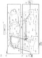
図28は、従来のプロテクション切替技術の動作の仕組みを示すネットワーク図である。本図のネットワークは、複数のユーザ端末(例えば、PCや企業内サーバ等)140を収容する中継網エッジ装置TE(Transport Edge)−Z(100−Z)と、一つまたは複数のデータサーバ120を収容する中継網エッジ装置TE−A(100−A)とを、パケット(OSI(Open Systems Interconnection)モデルの伝送レイヤではヘッダとペイロードから成るデータフォーマットをフレームと称する。以降の説明では、慣例に従ってパケットとフレームの両方を使用する。)中継網110で接続する構成である。ここで、データサーバ120からユーザ端末140へ向かう通信を想定し、以降の説明ではTE−A(100−A)側をパケット中継網の上位側、TE−Z(100−Z)側を下位側と称する。また、パケット中継網110は多数の中継網エッジ装置や中継装置の組合せで構成されるが、ここでは説明を簡単にするため、TE−A(100−A)、TE−Z(100−Z)、TE−A(100−A)とTE−Z(100−Z)との通信を中継するために配備した中継装置TN(Transport Node)−X(150−X)、TN−Y(150−Y)、TN−B(151−B)、TN−C(151−C)を用いた構成例を示している。本ネットワークは、TE−A(100−A)からTE−Z(100−Z)へパケットを中継するため、経路、170−w1、170−w2、170−w3を通過する経路を現用系経路1000、経路170−p1、170−p2、170−p3を通過する経路を予備系経路2000とした冗長化構成である。該ネットワークは、一般的には、TE−A(100−A)、TE−Z(100−Z)、TN−X(150−X)、TN−Y(150−Y)、TN−B(151−B)、TN−C(151−C)以外にも多くの中継網エッジ装置や中継装置が相互に接続されパケット中継網110を構成する。
Example 1
FIG. 28 is a network diagram showing a mechanism of operation of the conventional protection switching technique. The network in this figure includes a relay network edge device TE (Transport Edge) -Z (100-Z) that accommodates a plurality of user terminals (for example, PCs and in-house servers) 140, and one or a plurality of
パケット中継網110の内外には一つまたは複数のデータサーバ120が存在する。これらデータサーバ120は、パケット中継網110を構成するTE−A(100−A)等の中継網エッジ装置を介してユーザ端末140に対しユーザデータを配信する。
One or
データサーバ120からユーザ端末140宛のユーザデータを受信したTE−A(100−A)は、自装置内の経路表71(詳細は後述)を参照し、現用系経路1000を用いてユーザデータを転送する。現用系経路1000を介して中継を行う場合のユーザデータの通過経路を経路160とする。
The TE-A (100-A) that has received the user data addressed to the
TE−A(100−A)とTE−Z(100−Z)はOAM機能により現用系経路1000、予備系経路2000、2001の接続性を監視している。接続性を監視する信号(接続性監視信号)として、具体的には、TE−A(100−A)がTE−Z(100−Z)に対して送信する、ITU−T G.8013/Y.1731で規定されているCCM(Continuity Check Message)フレームがある。CCMフレームを使用し、周期Tで(周期Tはオペレータにより任意に設定可能)現用系経路1000および予備系経路2000に配信し、TE−Z(100−Z)にて当該CCMフレームの到着状況を確認することにより接続性を監視している。また、同じく接続性監視信号の1つとして冗長系の経路切替を監視し制御する信号、具体的には、TE−Z(100−Z)がTE−A(100−A)に対して送信する、ITU−T G.8013/Y.1731およびITU−T G.8031/Y.1342で規定されているAPS(Automatic Protection Switching)フレームがある。TE−Z(100−Z)は、APSフレームを通常時は5秒周期で予備系経路2001を介して送信し、現用系経路1000と予備系経路2000について経路切替の要否をTE−A(100−A)に通知している。
TE-A (100-A) and TE-Z (100-Z) monitor the connectivity of the
この時、TE−A(100−A)はデータサーバ120からユーザフレームを受信すると、経路表71で宛先を確認し、現用系経路1000に該ユーザフレームを転送する。ここで、TE−Z(100−Z)の現用系経路1000に接続性障害が発生した際、即ち、TE−Z(100−Z)が現用系経路1000からCCMフレームを3.5周期以内に1度も受信しなかった際に、APSフレームのRequest/Stateフィールドを設定し、更に予備系経路2001へのAPSフレームの送信周期を5秒周期から3.3ミリ秒周期に変更する。TE−A(100−A)はAPSフレーム内のRequest/Stateフィールドを参照して、現用系経路1000で障害が発生したことを検知し、現用系経路1000から予備系経路2000へ配信経路を切り替える。
At this time, when the TE-A (100-A) receives the user frame from the
現用系経路1000における障害発生に対し、予備系経路2000に切り替えを完了するには一定の処理時間が必要である。障害発生から切替完了までの間にデータサーバ120からTE−A(100−A)へ到達するユーザフレームは現用系経路1000へ転送される。従って、これらのユーザフレームはTE−Z(100−Z)まで届かず、ユーザ端末から見ると通信が途絶した状態になる。
A certain processing time is required to complete the switching to the
以下、実施例を図面を用いて説明する。図1は、本実施例で想定する通信システムの基本構成を示すネットワーク図である。既に説明した図28に示された同一の符号を付された構成と同一の機能を有する構成要素については、説明を省略する。ここでは、下り方向の接続性の監視、およびプロテクション切替の動作を説明する。先述したように、現用系経路1000、予備系経路2000はOAM機能により接続性の監視をしているが、現用系経路1000で通信障害が発生した際に予備系経路2000に切り替わるまでに時間を要し、その間の通信が途切れてしまう。そこで、パケット中継網110の内部又は外部に用意した補助通信経路3000を用いて、切替処理に伴って欠損する可能性のあるユーザデータを救済する。補助通信経路3000には、予備系経路2000に切り替わるまでの間の一時的な迂回経路として迂回経路3001、3101と迂回経路3002、3102を設定する。それぞれ、現用系経路1000を構成するTN−Y(150−Y)、TN−X(150−X)とTE−Z(100−Z)とを接続する回線である。迂回経路3001、3101と迂回経路3002、3102は物理的又は論理的な回線として構成する。迂回経路の具体的な設定例に関しては後述する。
Hereinafter, examples will be described with reference to the drawings. FIG. 1 is a network diagram showing a basic configuration of a communication system assumed in this embodiment. The description of the components having the same functions as those already described with reference to FIG. 28 is omitted. Here, the operation of monitoring connectivity in the down direction and protection switching will be described. As described above, the
TE−Z(100−Z)は、現用系経路1000で通信障害が発生した際、即ち、現用系経路1000からCCMフレームを3.5周期以内に1度も受信しなかった際に、5秒周期で予備系経路2001方向に配信していたAPSフレームを、3.3ミリ秒毎に予備系経路2001方向に配信するよう変更する。その際、予備系経路2001に加え、迂回経路3001、3002に対しても同様にAPSフレームを送出する。
TE-Z (100-Z) is 5 seconds when a communication failure occurs in the
なお、迂回経路3001、3002へのAPSフレーム送出は、現用系経路1000で通信障害が発生する前から、予備系経路2001への配信と同様に5秒周期で配信していてもよい。その場合、現用系経路1000で通信障害が発生すると、5秒周期で迂回経路3001、3002方向に配信していたAPSフレームを、3.3ミリ秒毎に迂回経路3001、3002方向に配信するよう変更する。
Note that the APS frame transmission to the
TE−Z(100−Z)が送出するAPSフレームはTE−Z(100−Z)に近い順に各通信装置へ到達する。即ちTN−Y(150−Y)、TN−X(150−X)、TE−A(100−A)の順に該APSフレームが到着する。TN−Y(150−Y)、TN−X(150−X)、TE−A(100−A)は、それぞれ該APSフレームを受信し、かつ、該APSフレーム内のRequest/Stateフィールドを参照して、切替要否(現用系経路1000での障害有無)を判定する。切替が必要な場合、TN−Y(150−Y)、TN−X(150−X)、TE−A(100−A)は、上位側から受信したユーザフレームを、迂回経路3101、3102および予備系経路2000に転送する。APSフレームのTN−Y(150−Y)、TN−X(150−X)、TE−A(100−A)への到着時刻が異なるため、経路170−w3から迂回経路3101、経路170−w2及び170−w3から迂回経路3102、経路170−w1を含む全現用系経路1000から予備系経路2000、の順に経路切替を行う。
The APS frame sent out by TE-Z (100-Z) reaches each communication device in the order close to TE-Z (100-Z). That is, the APS frames arrive in the order of TN-Y (150-Y), TN-X (150-X), and TE-A (100-A). TN-Y (150-Y), TN-X (150-X), and TE-A (100-A) each receive the APS frame and refer to the Request / State field in the APS frame. Thus, it is determined whether or not switching is necessary (whether or not there is a failure in the working path 1000). When switching is necessary, the TN-Y (150-Y), the TN-X (150-X), and the TE-A (100-A) receive the user frames received from the higher-level side as the
つまり、従来は予備系経路2000に切り替わるまでのユーザフレームは障害が発生した箇所で廃棄されており、予備系経路2000に切り替わるまでの間のデータ通信が途切れていたが、本実施例により、一時的な迂回経路3101や3102を利用してデータ通信の途切れる時間を短縮できる。なお、一時的な迂回経路3101や3102は常時ユーザフレームを転送することを想定していなかったり、他のユーザフレームの経路と共用であったりするので、迂回経路を通るユーザフレームについては、予備系経路2000を通るように経路を切り替えていくことが望ましい。
That is, conventionally, the user frame until switching to the
障害時にデータトラフィックを保護するための補助通信経路3000(迂回経路3101や3102)を構築するには主に2つの方法がある。一つはデータプレーン内に補助経路3000を設定する方法であり、もう一つは制御プレーンを補助経路3000として利用する方法である。ここで、データプレーンとは、ユーザフレームやOAMフレームの処理を行うネットワークであり、制御プレーンとは、制御用フレームの処理を行うネットワークである。データプレーンを利用する場合、パケット中継網110を構成する中継装置のうち、現用系経路1000は予備系経路2000を構成しない、別の中継装置を接続して迂回経路を設定することができる。以降では、迂回経路として制御プレーンを利用する場合とデータプレーンを利用する場合のそれぞれについてプロテクション切替を利用したトラフィック保護方法を説明する。なお、迂回経路の設定にあたり、データプレーンを利用する場合と制御プレーンを利用する場合とでは設定する方法は同じ(運用システムOpS(Operation System)による監視制御)である。
There are mainly two methods for constructing the auxiliary communication path 3000 (the
図2は、図1のネットワーク図において、迂回経路の設定方法の一例を示したネットワーク図である。図2は、図1のネットワーク図における一時的な迂回経路3001、3002を、制御プレーン181内の経路および装置を使用するように図示したものである。図1で記述した一時的な迂回経路3001、3002は、OpS112を利用してネットワーク管理者が設定することができる。OpSとは、一般的に、基地局・加入者の登録作業、試験障害監視などシステムの設定・監視・制御・試験を遠隔で行うシステムを言う。ここではそのソフトウェアを持つ制御用の端末をOpS112で示す。
FIG. 2 is a network diagram showing an example of a method for setting a bypass route in the network diagram of FIG. FIG. 2 illustrates
OpS112は、制御用のネットワークである制御プレーン181を構成する通信装置N152−1、N152−n、N153−1、N153−n、N154、N155、N156、N157のいずれか一つまたは複数の通信装置を介してパケット中継網110を構成する通信装置TE−A(100−A)、TE−Z(100−Z)、TN−X(150−X)、TN−Y(150−Y)にアクセスできる。OpS112は、制御プレーン181を介して、ユーザフレームやOAMフレームの処理を行うデータプレーン180を構成する通信装置と、経路設定情報や運用・監視情報を含む通信網運用情報を相互に伝達することができる。本図ではデータプレーン180内の通信装置が、それぞれ制御プレーン181内の通信装置と接続され、OpS112と直接または間接的に通信可能であることを示す構成とした。これらの条件を満たせば、制御プレーンの経路構成方法は本図と異なっていても構わない。
The
OpS112がデータプレーン180内の通信装置を制御する経路を制御線、主信号が流れる経路を主信号線と呼ぶ。本図では制御線を5001〜5008で示す。OpS112は制御線だけでなく、制御線と主信号線を介してデータプレーン180の通信装置を制御できる。通常、制御線は主信号線と比較して帯域が少ない。一般的には、制御線を介してOpS112でデータプレーン180の通信状態を監視し、データプレーン180内でプロテクションを実施する。
A path through which the
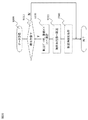
図3は、TE−Z(100−Z)の装置構成例を示す機能ブロック構成図である。本図を用いて、TE−Z(100−Z)における装置管理並びに通信信号処理について説明する。TE−Z(100−Z)には、他の通信装置やサーバ、或いは端末装置等と接続するために、一つ又は複数の通信インタフェース11−1〜11−Nを備える。これらのインタフェース11をインタフェース部10に含み、インタフェース11を通じて受信した信号は入力バッファ21−1へ蓄積する。受信した信号を処理する機能ブロックとして、入力出力制御部21、22や入力フレーム処理部31、出力フレーム処理部32、OAM制御部52がある。入出力制御部21は、入力バッファ21−1内部への書き込み開始や、入力バッファ21−1から入力フレーム処理部31へフレーム転送する際のタイミング指示を行う。インタフェース部10で信号入力を検知すると、入出力制御部21にフレーム到着を通知すると共に、入力バッファ21−1に入力信号を記録する。経路81及び81−1は、それぞれインタフェース部10から入出力制御部21、入力バッファ21−1へのフレーム(主信号)を含む信号伝送又は新規フレーム到着/未着状態を含む装置内状態(或いは通信状況)の監視・制御に用いる信号経路である。
FIG. 3 is a functional block configuration diagram illustrating a device configuration example of TE-Z (100-Z). Device management and communication signal processing in TE-Z (100-Z) will be described with reference to FIG. The TE-Z (100-Z) includes one or a plurality of communication interfaces 11-1 to 11-N in order to connect to other communication devices, servers, or terminal devices. These
本図の中で、インタフェース部10に接続する回線10−1〜10−Nは、物理回線又は論理回線を示す。信号フレームはVLAN(Virtual Local Area Network)やMPLS(Multi Protocol Label Switching)タグを用いて論理的に識別されることが通例である。例えばインタフェース10−1〜10−Nを物理インタフェースと見做すと、個々のインタフェースには複数の論理回線10−1−1〜10−1−m1、10−2−1〜10−2−m2、10−N−1〜10−N−mNを含むことができる。個々の論理回線には、更に複数の論理回線を設定できる。例えば、VLANタグを複数使用するか、MPLSでフレーム転送に用いられるシムヘッダを複数挿入することにより、多段階層から成る論理回線設定が可能である。
In the figure, lines 10-1 to 10-N connected to the
受信フレームが入力バッファ21−1から入力フレーム処理部31に転送されると、入力フレーム処理部31では、受信フレームの種別判定(プロトコル識別、主信号/制御信号識別など)やフレームヘッダの抽出、宛先確認、ヘッダ情報の付与・変換・削除を行う。受信フレームの宛先確認では、入力フレーム処理部31は、受信フレームの宛先を示すヘッダ情報を抽出し、該情報を経路表71と照合する。経路表71には受信フレーム毎に該当する宛先へ向けて該フレームを送出するための通信経路情報を保持する。通信経路情報には、送出するインタフェースの識別子及び送出時に該フレームに付与すべきヘッダ情報を含む。
When the received frame is transferred from the input buffer 21-1 to the input
送出先が決定したフレームは、スイッチ部50により宛先毎に振り分けられる。即ちスイッチ部50は複数のインタフェースボード間を接続する役割を担っており、例えばスイッチ部50に入力されるフレームに付属する前述のヘッダ情報(フレーム本体のヘッダ情報又は装置内部のみで使用する「内部ヘッダ(例えば、送出先ポート識別子)」情報)に基づき、当該フレームを送出すべき物理/論理インタフェースを備えるインタフェースボード宛てに転送される。経路83は、入力フレーム処理部31からスイッチ部50にフレームを送出する信号経路である。本図では通信装置の機能ブロックの相関関係を簡略化して図示しているため具体的な実現方法には触れていないが、このようなスイッチ部50の役割を担う信号処理基板と、個々のインタフェースを含むインタフェース用基板とをバックプレーンを用いて相互に接続する構成は一般的に用いられる。一般的には本図の中でスイッチ部50のみ別基板上に実装されることも珍しくない。但し、具体的な実装方法の差異は本発明及び本実施の形態の本質とは関係しないため、詳細な説明は割愛する。スイッチ部50は、入力されるフレームの転送先(インタフェースボード、或いはインタフェースグループ)を決定する際に、当該フレームのヘッダ情報や内部に備える記憶部70の経路表71を比較参照することにより決定する。スイッチ部50は、入力されるフレームの転送先を決定すると、転送先の出力フレーム処理部32へ出力フレームとして転送する。
The frame for which the transmission destination is determined is distributed to each destination by the
以上の流れから、スイッチ部50から出力フレーム処理部32が受信するフレームは、当該出力フレームが属するインタフェースボード上のインタフェース部10より外部に転送されるべきフレームである。経路84は、スイッチ部50から出力フレーム処理部31にフレームを送出する信号経路である。出力フレーム処理部32は、出力フレームをインタフェース部10宛てに送出する迄の最後の処理を行うブロックであり、入力フレーム処理部31と同様の処理を行う。即ち、出力バッファ22−1に出力フレームを記録し、インタフェース部10へフレーム転送する際のタイミング指示を行う。
From the above flow, the frame received by the output
また、ヘッダ情報の処理や、優先度別の送出処理(フレーム順序調整)を行う。出力フレーム処理部32にて、スイッチ部50から受信した出力フレームを具体的に送出するインタフェース11−1〜11−Nを選択する。ヘッダ情報の処理は、例えば装置内部におけるフレーム処理に用いる内部ヘッダの削除、入力側と出力側とでプロトコルが異なる場合等の、ヘッダ情報の変更・付加・削除或いは処理状況を記録しておくためのフレーム情報の読取り処理が必要な場合に実施する。
Also, header information processing and priority-specific transmission processing (frame order adjustment) are performed. In the output
制御信号入出力処理部90は制御信号を処理する。ノード制御部51は、TE−Z(100−Z)全体を制御するために設けられた制御部である。ノード制御部51は、オペレータがOpS112を介して設定する情報を基に、経路表71の設定、更新および管理することで、TE−Z(100−Z)に入力されたユーザフレームに対する出力先を決定する。
The control signal input /
オペレータは、前述の経路情報に関する設定を、TE−Z(100−Z)以外の各装置(例えば図1では、TE−A(100−A)、TN−X(150−X)、TN−Y(150−Y))にも同様に施すことで、オペレータが設計した通信経路(例えば、前述した現用系経路1000)をネットワーク全体として実現している。その他にも、ノード制御部51は入出力処理部52やスイッチ部50などのTE−Z(100−Z)各構成ブロックの状態を監視し、必要に応じてOpS112へ該装置の状態を通知する。オペレータはOpS112を介して、前述の通知を受けることで、該装置の状況を把握し、保守業務などを実現している。
The operator sets the above-described setting regarding the route information to each device other than TE-Z (100-Z) (for example, TE-A (100-A), TN-X (150-X), TN-Y in FIG. 1). (150-Y)) is also applied in the same manner, so that the communication route designed by the operator (for example, the above-described active route 1000) is realized as the entire network. In addition, the
ここで、主信号用物理回線10−1〜10−Nは、例えばIEEE803.2aeで規定されている10GBASE−SXの規格に従う。また制御信号用物理回線60はIEEE802.3anで規定されている10GBASE−Tの規格に従うものとする。ここで列挙したインタフェース規格はあくまで一例であり、本装置のインタフェース規定をこれに限定するものではない。
Here, the main signal physical lines 10-1 to 10-N comply with the 10GBASE-SX standard defined by, for example, IEEE 803.2ae. Further, the control signal
次に、TE−Z(100−Z)の特徴的な機能を説明する。TE−Z(100−Z)は、OAM技術を用いてTE−A(100−A)との接続性を監視する。OAMフレーム(CCMフレーム及びAPSフレーム)の処理方法を以下に説明する。 Next, characteristic functions of TE-Z (100-Z) will be described. TE-Z (100-Z) monitors connectivity with TE-A (100-A) using OAM technology. A method for processing the OAM frame (CCM frame and APS frame) will be described below.
入力フレーム処理部31において、受信フレームの種別判定を行った際に当該フレームがCCMフレームと識別された場合、OAM制御部72内のCCM終端部73で終端する。また、OAM制御部72は、APS挿入部74でAPSフレームを生成し、スイッチ部50を介して、予備系経路2001及び迂回経路3001、3002にAPSフレームを送出する。尚APSフレームを迂回経路3001、3002に送出する際には、制御信号用物理回線60(及び論理回線5001や5002が設定されている場合には当該論理回線)を介して制御プレーン181宛に送出する。
When the input
OAM制御部72は、CCM終端部73でCCMフレームの到着周期を監視する。CCM終端部73でCCMフレームを現用系経路から3.5周期以内に1度も受信しなかった場合、現用系経路1000で通信障害が発生したと判定する。障害が検知された場合、APS挿入部74は、平常時に5秒周期で予備系経路2001および迂回経路3001、3002へ送信していたAPSフレーム送信周期を3.3ミリ秒に変更し、通信経路切替を要求するためRequest/Stateフィールドに状態遷移情報(例えば、現用系信号故障を表す1011)を埋め込む。
The OAM control unit 72 monitors the arrival period of the CCM frame at the
障害発生後、TE−A(100−A)における経路切替処理が完了するまでの間にTE-A(100−A)が現用系経路1000を用いて送信したユーザフレームは、迂回経路3101、3102を介してTE−Z(100−Z)に到着する。この時、当該ユーザフレームは、通常のデータプレーン内インタフェース11−1から11−Nを介して到着するのではなく、制御回線5001、5002あるいは制御信号用物理回線60を介して到着する。即ち、ノード制御部51は、受信したユーザフレームを入出力制御部21へ経路86を介して転送し、入出力制御部21は該ユーザフレームについて、データプレーン180から受信したフレームと同様に終端又は伝送処理を行う。ノード制御部では切替要求フラグを含むAPSフレームを送出した時点で、制御回線5001、5002、制御信号用物理回線60を介してユーザフレームを受信するための準備を行う。つまり平常時には許可していないユーザフレームでの制御線利用を認める(受信フィルタの変更)、入出力制御部21への障害発生及びノード制御部51を介したユーザフレーム受信用のバッファ確保や受信対象データの識別子通知などの処理を行う。経路85は、ノード制御部51とスイッチ部50が相互にフレームを送出する信号経路である。
User frames transmitted by the TE-A (100-A) using the
別の実装方法として、ユーザフレームの受信処理を入力フレーム処理部31に代わりノード制御部51が行っても良い。平常時に制御信号を処理するための信号処理機能を用いて、ユーザフレームを終端し、入力フレーム処理部31へ経路87を介してユーザフレームを受け渡す方法でも実現可能である。更に別の方法として、OAM制御部72がAPSフレームを送出した時点で障害が発生した経路の識別子を含む、OAM制御に必要な情報(パラメータ)をノード制御部51へ通知する(或いはノード制御部が予めこれら情報を保持しておく)ことにより、ノード制御部51内で全てのユーザフレームの処理を完了し、当該ユーザフレームをスイッチ部50へ転送することも可能である。
As another mounting method, the
図4は、TE−Z(100−Z)が保持する経路表71のテーブル構成例である。データ210〜216は、テーブルのエントリを表す。本テーブルは、例えば一般的な通信キャリア網では、通信サービスの開始に先立って、OpS112により静的に設定される。本テーブルには、オペレータがパケット中継網110を管理・運用するためのパスID(IDentification)(VLAN ID又はMPLSタグ)201、宛先MACアドレス202、宛先ポート(パスID毎にそれぞれ設定される送出インタフェース)番号203が格納される。パスID201を示すためにVLANタグやMPLSのシムヘッダを複数段使用することも、VLAN IDとMPLSラベルとを複数ずつ組み合わせて用いることもできる。パスID201と宛先MACアドレス202は処理対象フレームのヘッダ情報として含まれており、本テーブルを検索する際の検索キーとして利用できる。例えば宛先MACアドレス202は、同一のVLANに属する宛先ポート識別子が複数存在する場合などに、宛先ポート番号を特定するために用いることができる。経路表71の検索時には、これら検索キーで示されるエントリ毎に規定される宛先ポートID203を抽出し、当該フレームの送信先及び転送処理時に必要となるヘッダ情報を決定する。
FIG. 4 is a table configuration example of the path table 71 held by TE-Z (100-Z).
また、TE−Z(100−Z)の経路表71には、現用系経路で通信障害が発生した場合にAPSフレームを送出する経路である予備系経路2001/迂回経路3001、3002用のポート番号204を保持する。通常のフレーム転送処理時には、本テーブルの宛先ポート番号203を検索して受信フレームを転送する。ユーザフレームはTE−Z(100−Z)からユーザ端末140へ向けて転送されるため、ユーザフレームの転送処理では常時宛先ポート番号203を使用する。一方、通信障害が発生した場合にAPSフレームを送出する際には、APSフレーム送出対象(OAMでの監視対象)経路を、パスID201を用いて本テーブルから検索し、当該エントリの予備系/迂回経路向け宛先ポート番号204を抽出して当該経路宛てヘッダ情報を付与する。すなわちAPSフレームの生成及び送出に際しては、常に対象経路のエントリに記載される予備系/迂回経路向けポート番号204を用いる。本実施例のようにAPSフレームを予備系経路だけでなく1つ又は複数の迂回経路へも送信する場合、本図のように予備系/迂回経路向けポート番号204に複数のポート番号を格納した構成とする。これにより、APSフレーム送出対象経路について登録された予備系/迂回経路向け宛先ポート番号204から複数のポート番号を抽出し、該抽出した全ポート番号宛にAPSフレームを送信する。
Also, the TE-Z (100-Z) path table 71 shows the port numbers for the backup path 20011 and the
また、本テーブルには切替えフラグ200を持つこともできる。本フラグには、各エントリのパスID201(受信フレームの入力経路)が現用系経路1000に対応するものか予備系/迂回経路のいずれかに対応するものかによってそれぞれ“0”又は“1”を挿入する。予備系/迂回経路から受信するユーザフレームは、TE−Z(100−Z)でデータの欠損や重複が生じないようにフレームの到着状況を確認した後、ユーザ端末140へ転送する。そこで、現用系経路1000に障害が発生しているときなど、切替えフラグが“1”のエントリに対しては、当該予備系/迂回経路から受信するフレームの到着状況を優先的に監視する必要があり、例えば入出力制御部21や入力フレーム処理部31のバッファを優先的に開放するなどの補助的な処理を行うことができる。
This table can also have a switching
図5は、TN−Y(150−Y)の装置構成例を示す機能ブロック構成図である。本図を用いて、TN−Y(150−Y)における装置管理並びに通信信号処理について説明する。TE−Z(100−Z)と同様な機能は説明を割愛する。以下に、TN−Y(150−Y)の特徴的な機能を説明する。 FIG. 5 is a functional block configuration diagram showing a device configuration example of TN-Y (150-Y). Device management and communication signal processing in TN-Y (150-Y) will be described with reference to FIG. Description of functions similar to those of TE-Z (100-Z) is omitted. Hereinafter, characteristic functions of TN-Y (150-Y) will be described.
TN−Y(150−Y)の重要な役割に、APSフレームを終端し経路切替の要否を確認すること、及び経路切り替えに伴いTE−Z(100−Z)宛てに、切替対象となる経路を流れるユーザフレームを転送することが挙げられる。TN−Y(150−Y)は通常、迂回経路3001又は制御信号用物理回線60を介して5秒毎にAPSフレームを受信し、処理部であるOAM制御部720内のAPS終端部750でAPSフレームを終端する。ノード制御部510では、制御フレーム以外のフレームを受信した場合に、当該フレームを入出力制御部21へ転送する。尚、別の実装方法として、ノード制御部510内にAPSフレーム識別機能を備え、APSフレームのみを選択的に入出力制御部21又は入力フレーム処理部31へ転送しても良い。また別の実装例として、ノード制御部510内部にAPSフレーム終端部750相当の機能ブロックを実装し、APSフレームを終端、切替要否の判断を行っても良い。切替手順をまとめると、(1)ノード制御部510又はOAM制御部720にて経路切替要否を判定し、(2)切替対象となる経路を識別する経路識別子を抽出して当該経路を流れるユーザフレームを抽出、(3)更に切替後の通信経路を識別し、(4)該ユーザフレームを当該経路へ転送することが出来ればよい。手順(2)の一部及び(3)はOAM制御部720により処理する。手順(2)におけるデータ抽出と(4)のフレーム転送は入力フレーム処理部にて行う。
The important role of TN-Y (150-Y) is to terminate the APS frame and confirm the necessity of path switching, and to the path to be switched to TE-Z (100-Z) along with path switching. And forwarding user frames that flow through The TN-Y (150-Y) normally receives an APS frame every 5 seconds via the
ノード制御部510又はAPS終端部750でRequest/Stateフィールドに切替動作が必要になる状態遷移を伝える情報を埋め込まれたAPSフレームを受信した際、ノード制御部510又はOAM制御部720は、入出力処理部520に対して該当する経路についてユーザデータの転送経路を切替えるよう指示する。経路切替の指示を受けた入出力処理部520は、入力フレーム処置部31で受信したフレームを、記憶部700の経路表710(もしくは経路表710とパス管理補助テーブル760(後述))を参照して迂回経路へ転送する。
When the
図6は、TN−Y(150−Y)が保持する経路表710のテーブルの一つ目の構成例(経路表710a)、図8は、経路表710のテーブルの二つ目の構成例(経路表710b)である。また、図7は、TN−Y(150−Y)が保持するパス管理補助テーブル760である。経路切替えを行う際には、二つの手段を用いることができる。一つ目の手段(以降、手段Aとする)はパスIDの異なる現用系経路と予備系経路を相互に切り替える方法である(図6、7を用いる)。二つ目の手段(以降、手段Bとする)は、切替対象パスIDを変えずにユーザデータの振り分け先を変更することで経路を切り替える方法である(図8を用いる)。 6 shows a first configuration example (route table 710a) of the table of the route table 710 held by TN-Y (150-Y), and FIG. 8 shows a second configuration example of the table of the route table 710 (FIG. The route table 710b). FIG. 7 shows a path management auxiliary table 760 held by TN-Y (150-Y). When performing path switching, two means can be used. The first means (hereinafter referred to as means A) is a method of switching between the active path and the backup path with different path IDs (using FIGS. 6 and 7). The second means (hereinafter referred to as means B) is a method of switching paths by changing the user data distribution destination without changing the switching target path ID (using FIG. 8).
図6の経路表710aには、受信したフレームを送出する際の出力パスを識別する出力パスID(VLAN ID又はMPLSタグ)2200、宛先MACアドレス2210、宛先ポート番号2220が格納される。
The routing table 710a in FIG. 6 stores an output path ID (VLAN ID or MPLS tag) 2200 for identifying an output path when a received frame is transmitted, a
図7のパス管理補助テーブルには、受信したフレームの入力パスを識別する入力パスID(VLAN ID又はMPLSタグ)7700、出力パスIDとして、現用系のパスを識別する現用系パスID(VLAN ID又はMPLSタグ)7710と迂回系のパスを識別する迂回系パスID(VLAN ID又はMPLSタグ)7720、受信したフレームを出力する経路(現用系か迂回系か)を識別する現/予識別フラグ7730が格納される。
The path management auxiliary table of FIG. 7 includes an input path ID (VLAN ID or MPLS tag) 7700 for identifying an input path of a received frame, and an active path ID (VLAN ID) for identifying an active path as an output path ID. (Or MPLS tag) 7710 and a detour path ID (VLAN ID or MPLS tag) 7720 for identifying a detour path, and a current /
図8の経路表710bには、パスID(VLAN ID又はMPLSタグ)2510、宛先MACアドレス2520、宛先ポート番号として、現用系のパスを識別する通常経路向け宛先ポート番号2530と迂回系および予備系のパスを識別する迂回/予備系経路向け宛先ポート番号2540、受信したフレームを出力する経路を切り替える切替フラグ2500が格納される。
The path table 710b of FIG. 8 includes a path ID (VLAN ID or MPLS tag) 2510, a
まず手段Aは、経路170−w3のパスIDと対になる迂回経路3101のパスIDを別々にテーブル(図6、7)に保持しておき、障害発生時には迂回経路3101に対応するパスIDのエントリを参照する。このとき現/予識別フラグ7730を用いて、通常経路を利用するエントリは“0”、迂回経路を利用するエントリは“1”としておくと、テーブル参照を容易に実施できる。具体的には、TN−Y(150−Y)では上位側エッジ装置であるTE−A(100−A)から送られてくるユーザフレームについて、パス管理補助テーブル760の入力パスID7700を参照し、該エントリの現/予識別フラグ7730を確認する。該ユーザフレームの現/予識別フラグ7730が“0”であれば現用系パスID7710、“1”であれば迂回系パスID7720を出力パスIDとして抽出し、抽出した出力パスIDをキーに図6の経路表710aの出力パスID2200を検索する。対応エントリの宛先MACアドレス2210もしくは宛先ポート番号2220を参照して下位側TE−Z(100−Z)へ転送する。
First, the means A holds the path ID of the
また、手段Bは、パスIDを変えずにユーザフレームの振り分け先を変更する方法である。図8のテーブルにある切替フラグ2500を用い、“0”の場合は当該エントリの通常経路向け宛先ポート番号2530を参照し、“1”の場合には迂回/予備系経路向け宛先ポート番号2540を参照するようにすれば、同一のエントリに記載される宛先ポート番号2530、2540を使い分けてユーザフレームを出力することができる。手段Aでは各エントリは通常経路(現用系)か迂回経路(迂回系)のいずれかの宛先ポート番号しか登録する必要がないが、手段Bでは各エントリは通常経路/予備経路の両情報を登録しておき、切替フラグ2500を用いて宛先ポート番号を切替えられる。
Means B is a method of changing the user frame distribution destination without changing the path ID. The switching
図9は、TE−Z(100−Z)が現用系経路1000から予備系経路2000へ経路切替の流れを示すシーケンス図である。TE−A(100−A)はサービス開始(300)後、TE−Z(100−Z)宛てにCCMフレームやユーザフレームを、現用系経路1000を介して送信する(350〜350−n)。通信障害330が発生してTE−Z(100−Z)が障害を検知すると(301)、APSフレーム内のRequest/Stateフィールドを障害が発生したことがわかるよう変更したAPSフレームをTN−Y(150−Y)、TN−Y(150−Y)、TE−A(100−A)宛に配信する(351、352、353)。TN−Y(150−Y)は該APSフレームを受信すると、TE−A(100−A)から受信したユーザフレームを、迂回経路3101に転送するように切り替える(303)。TN−Y(150−Y)がCCMフレームを受信した際に迂回経路3101に転送するかそのまま現用系経路170−w3に転送し続けるかはどちらでもよい。次に、TN−X(150−X)は該APSフレームを受信すると、TE−A(100−A)から受信したユーザフレームを、迂回経路3102に転送するように切り替える(305)。TN−X(150−X)がCCMフレームを受信した際に迂回経路3102に転送するかそのまま現用系経路170−w3に転送し続けるかはどちらでもよい。最後に、TE−A(100−A)は該APSフレームを受信すると、TN−Y(150−Y)やTN−X(150−X)と同様、データサーバ120から受信したユーザフレームを、予備系経路2000に転送するように切り替える(307)。切替後は、現用系経路1000を介して送信していたCCMフレームやユーザフレームを予備系経路2000に送信し(361)、予備系経路2000を用いた通常運用が開始する(362)。
FIG. 9 is a sequence diagram showing a flow of switching the route from the
図10は、TE−Z(100−Z)のOAM制御部72による経路切替動作を示すフローチャートである。OAM制御部72はCCMフレームの受信状態を監視(400)しており、CCMフレームを3.5周期以内に1度でも受信した場合(400のN)は、現用系に障害無しと判断して現用系経路からの受信を継続する。(401)。一方、TE−Z(100−Z)がCCMフレームを3.5周期以内に1度も受信しなかった場合(400のY)、OAM制御部72は現用系経路に障害が発生したと判定し、予備系経路に送信していたAPSフレームのRequest/Stateフィールドに、切替動作が必要になる状態遷移を伝える情報を埋め込む(402)。更にOAM制御部72は、予めOpS112により設定された経路表71の予備系/迂回経路向けポート番号を参照して、一時的な予備系経路2001、迂回経路3001、3002を経由してTE−A(100−A)、TN−Y(150−Y)、TN−X(150−X)宛に該APSフレームを3.3ミリ秒周期で3回送信する(403)。3回送信後は、Request/Stateフィールドを通常の状態(通信障害発生前と同じ値)に戻し(404)、TE−A(100−A)、TN−Y(150−Y)、TN−X(150−X)宛に該APSフレームを通信障害発生前と同じ5秒周期で送信する(405)。尚、本発明の実施例で示すCCMフレーム、APSフレームの送信周期や送信回数等は標準規格の推奨値に基づく値であり、オペレータの運用方針等により設定値を任意に変更して構わない。
FIG. 10 is a flowchart showing a path switching operation by the OAM control unit 72 of TE-Z (100-Z). The OAM control unit 72 monitors the reception state of the CCM frame (400). If the CCM frame is received even once within 3.5 cycles (N of 400), it is determined that there is no failure in the active system. Continue receiving from the working path. (401). On the other hand, when TE-Z (100-Z) has never received a CCM frame within 3.5 cycles (Y in 400), the OAM control unit 72 determines that a failure has occurred in the working path. In the request / state field of the APS frame that has been transmitted to the backup path, information that conveys the state transition that requires the switching operation is embedded (402). Further, the OAM control unit 72 refers to the port number for the standby / detour path in the path table 71 set in advance by the
図11は、TN−Y(150−Y)のOAM制御部720による経路切替動作を示すフローチャートである。TN−X(150−X)も同じ動作をするが、ここでは例としてTN−Y(150−Y)の動作を説明する。OAM制御部720は障害を通知するAPSフレームを受信すると(501)、該APSフレームの入力パスIDを抽出する(502)。その後、パス管理補助テーブル760を参照して、該エントリの現/予識別フラグ7730に“1”を立てる(503)。
FIG. 11 is a flowchart illustrating a path switching operation by the TN-Y (150-Y)
図12は、TN−Y(150−Y)またはTN−X(150−X)の入力フレーム処理部31による経路切替動作を示すフローチャートである。入力フレーム処理部31はユーザフレームを受信すると(5010)、該ユーザフレームのヘッダ情報から入力パスIDを抽出する(5011)。その後、パス管理補助テーブル760を参照して、該エントリの現/予識別フラグ7730が“0”であるかどうかを判別する。現/予識別フラグ7730が“0”の場合(5012のY)、出力パスIDとして現用系パスID7710を抽出して(5013)、出力パスID7710をキーに経路表710で宛先MACアドレス2210や宛先ポート番号2220を検索する(5014)。その後、現用系経路宛にユーザフレームを転送する(5015)。5012においてパス管理補助テーブル760を参照して、該エントリの現/予識別フラグ7730が“0”でない場合(5012のN)、すなわち、現/予識別フラグ7730が“1”の場合、出力パスIDとして迂回系パスID7720を抽出して(5016)、出力パスID7720をキーに経路表710で宛先MACアドレス2210や宛先ポート番号2220を検索する(5017)。その後、迂回系経路(予備系経路)宛にユーザフレームを転送する(5018)。
FIG. 12 is a flowchart showing a path switching operation by the input
以上より、現用系経路で障害が発生した時、予備系経路に切り替わるまでに、ユーザが認識するサービスの障害時間を短縮することができる。図9を用いて、通常の1:1プロテクション切替と本実施例のサービスの障害時間の比較を説明する。 As described above, when a failure occurs in the active route, the failure time of the service recognized by the user can be shortened before switching to the backup route. A comparison of normal 1: 1 protection switching and the failure time of the service of this embodiment will be described with reference to FIG.
従来の1:1プロテクション切替ではTE−Z(100−Z)からTE−A(100−A)に切り替わるまでに時間Nがかかる。一方、本実施例では、TN−Y(150−Y)からTE−Z(100−Z)の間で通信障害330が発生した場合は、迂回経路3101へ切替が完了する303までの時間Lがかかる。時間Lが、ユーザが認識するサービスの障害時間となる。時間Lは時間Nと比較して、通信遮断時間が少ないのは明らかである。また、TN−Y(150−Y)からTN−X(150−X)の間で通信障害330が発生した場合は、迂回経路3101へ切替が完了する303までの時間Mがかかる。時間Mは時間Nと比較して、通信遮断時間が少ないのは明らかである。
In conventional 1: 1 protection switching, it takes time N to switch from TE-Z (100-Z) to TE-A (100-A). On the other hand, in the present embodiment, when a
図13は、現用系経路で通信障害が発生して優先度の高いユーザデータを迂回経路へ転送する際のネットワーク図である。データプレーン180内の通信装置が、それぞれ制御プレーン181内の通信装置と接続され、OpS112と直接または間接的に通信可能であることを示す構成の場合、OpS112は制御線と主信号線を介してデータプレーン180の通信装置を制御できるが、通常、制御線は主信号線と比較して帯域が少ない。制御線の帯域が少ないため、現用系経路で通信障害が発生した際に、予備系経路へ切り替えるまでの一時的な迂回経路として制御線にユーザデータを転送するとき、ユーザデータの容量が大きい場合は優先度の高いデータであっても廃棄されてしまうことがある。ここで、優先度の高いユーザデータを迂回経路に転送して確実にユーザに届くように設定することもできる。詳細は以下の図を用いて説明する。優先度の高いユーザデータとは、例えば緊急性の高いデータ(緊急地震速報や津波・竜巻速報等)や動画等がある。
FIG. 13 is a network diagram when a high-priority user data is transferred to a detour path when a communication failure occurs in the working path. When the communication device in the
優先度の高いユーザデータの迂回経路への転送は、TN−Y(150−Y)またはTN−X(150−X)内の入力フレーム処理部31においてユーザデータ管理テーブル(詳細は後述する)を参照して、ユーザデータの優先度を識別し、該ユーザデータを迂回経路に転送するか廃棄(またはバッファに溜めて障害復旧後に再送)するかを決定して行う。該ユーザデータの優先度とは、例えば、CoS値により識別することができる。本ネットワーク図においては、通信障害が経路170−w3で発生しており、TN−Y(150−Y)内の入力フレーム処理部31でユーザデータの優先度の識別を行う。優先度の高い主信号線160は、入力フレーム処理部31において優先度が高いと識別され、迂回経路に転送されるのに対し、優先度の低い主信号線161は、入力フレーム処理部31において迂回経路に転送されずに廃棄(またはバッファに格納等)される。
The user data management table (details will be described later) in the input
ユーザデータ管理テーブル770とは、入力フレーム処理部31がAPS終端部750でRequest/Stateフィールドに切替動作が必要になる状態遷移を伝える情報を埋め込まれたAPSフレームを受信した際に該ユーザデータを迂回経路に転送するか廃棄(またはバッファに溜めて障害復旧後に再送)するかを決定するときに参照するテーブルであり、図5で説明したTN−Y(150−Y)またはTN−X(150−X)の記憶部700が保持する。
The user data management table 770 indicates that when the input
迂回経路へ転送するか廃棄するかを決定する方法は、静的に決定する方法と動的に設定する方法の2つの方法がある。静的に決定する方法は図14、15を用いて、また、動的に決定する方法は図16、17、18を用いて説明する。なお、ここでは、入力フレーム処理部31が迂回経路へ転送するか廃棄するかを決定すると説明するが、同様な機能を持った機能部であれば、入力フレーム処理部31に限定されない。
There are two methods for deciding whether to transfer to a detour route or to discard it: a static decision method and a dynamic setting method. A method for static determination will be described with reference to FIGS. 14 and 15, and a method for dynamic determination will be described with reference to FIGS. 16, 17 and 18. Here, it is described that the input
図14(a)(b)は、迂回経路へ転送するか入力フレーム処理部31で廃棄するかを静的に決定する場合におけるTN−Y(150−Y)が保持するユーザデータ管理テーブル770である。ユーザデータ管理テーブル770を基に優先度を識別する手段は2つある。1つ目の手段は、フレームに付与されているCoS値により優先度を識別する方法であり、手段Aとする。2つ目の手段は、イーサネットフレームのVLAN IDやMACアドレス、MPLSフレームのMPLSタグ等をパスIDとしてテーブルに格納して、パスIDにより優先度を識別する方法であり、手段Bとする。手段Aを利用する場合に参照するテーブルをユーザデータ管理テーブル(a)770a(図14(a))、手段Bを利用する場合に参照するテーブルをユーザデータ管理テーブル(b)770b(図14(b))とする。
FIGS. 14A and 14B are user data management tables 770 held by the TN-Y (150-Y) when statically determining whether to transfer to the detour path or discard by the input
まずは、ユーザデータ管理テーブル(a)770aについて説明する。本テーブルは、例えば一般的な通信キャリア網では、通信サービスの開始に先立って、オペレータがOpS112により設定する。データ7800〜7860は本テーブルのエントリを表す。本テーブルには、ユーザフレームに埋め込まれる優先度7910が格納される。優先度とは、ここではユーザフレーム内のCoS値のことである。優先度7910を参照して、迂回経路に該ユーザフレームを転送するか入力フレーム処理部31で廃棄するかの判別を行う。なお、ここでは、優先度7910の値が小さいものから順に優先度が高いとしている。つまり、優先度7910が「3」であるデータ7800が優先度「高」で、「9」であるデータ7860が優先度「低」である。
First, the user data management table (a) 770a will be described. For example, in a general communication carrier network, this table is set by the
上記判別方法は、例えば、本テーブルに予めユーザデータの迂回経路への転送(中継)の可否を特定する情報である転送/廃棄フラグ7920を持つことができる。本フラグには、各優先度7910のユーザフレームを入力フレーム処理部31で廃棄するか迂回経路に転送(中継)するかによってそれぞれ“0”又は“1”を挿入する。本フラグの設定は、通信サービスの開始に先立って、OpS112により静的に設定することができる。また、サービスの途中でオペレータが任意に変更することもできる。
For example, the determination method may have a transfer / discard
次に、ユーザデータ管理テーブル(b)770bについて説明する。本テーブルも、ユーザデータ管理テーブル(a)770aと同様、通信サービスの開始に先立って、オペレータがOpS112により設定する。データ8000〜8060は本テーブルのエントリを表す。本テーブルには、イーサネットフレームのVLAN IDやMACアドレス、MPLSフレームのMPLSタグ等をパスID8110として格納する。また、オペレータは、該パスIDに対応した優先度8120を予め格納する。これにより、パスID8110を検索キーとして、優先度8120を識別することができる。入出力処理部520は、優先度8120を参照して、迂回経路に該ユーザフレームを転送するか入力フレーム処理部31で廃棄するかの判別を行う。なお、優先度8120の値の高優先度、低優先度については図14(a)と同様である。
Next, the user data management table (b) 770b will be described. Similarly to the user data management table (a) 770a, this table is set by the
上記判別方法は、例えば手段Aと同様、本テーブルに予め転送/廃棄フラグ8130を持つことができる。本フラグの動作は手段Aと同様のため、説明は割愛する。ここで、エントリは優先度が高いものから順に並んで格納されているが、優先度順ではなくランダムに並ぶこともある。その場合も転送/廃棄フラグ8130に予めオペレータが設定することができる。なお、ここで本フラグ8130を設定した場合、優先度8120の設定はなくても良い。
For example, as in the means A, the determination method can have a transfer / discard flag 8130 in advance in this table. Since the operation of this flag is the same as that of means A, the description is omitted. Here, the entries are stored side by side in descending order of priority, but may be randomly arranged instead of in order of priority. Also in this case, the operator can set the transfer / discard flag 8130 in advance. If the flag 8130 is set here, the
図15は、迂回経路へユーザフレームを転送するか廃棄するかを静的に決定する場合の、TN−Y(150−Y)の入力フレーム処理部31による転送/廃棄決定動作を示すフローチャートである。本フローチャートは、現用系経路で通信障害が発生したことをTN−Y(150−Y)が検知した際に、その後受信したユーザフレームを迂回経路に転送する際の動作を示したものである。ここでは、例としてユーザデータ管理テーブル(a)770aを用いてフレームの転送先を決定する動作を説明する。
FIG. 15 is a flowchart showing a transfer / discard determination operation by the input
入力フレーム処理部31はユーザフレームを受信すると(6000)、該フレームのCoS値により優先度を抽出して、該優先度を検索キーとしてユーザデータ管理テーブル(a)770aにおいてエントリを検索する(6001)。次に、ヒットしたエントリの転送/廃棄フラグ7920を参照して、迂回経路へ該ユーザフレームを転送するかどうかを判別する(6002)。転送/廃棄フラグ7920が0の際、すなわち、迂回経路へ該ユーザフレームを転送しない場合は(6001のY)、該ユーザフレームを廃棄する(6003)。または、廃棄に代えて、入力バッファ21−1に該ユーザフレームを溜めて、障害復旧後に再送することもできる。または、現用系経路に転送し続けても良い。転送/廃棄フラグ7920が1の際、すなわち、迂回経路へ該ユーザフレームを転送する必要がある場合は(6001のN)、更に経路表710を参照してユーザフレームを迂回経路に転送する(6004)。ここで、ユーザフレームには当該データ通信を監視するためのOAMフレーム(例えば、TE−A(100−A)に外部から到着するOAMフレーム、或いはパケット中継網110でデータ通信をエンドツーエンドで監視するためにTE−A(100−A)とTE−Z(100−Z)が相互に送受信するOAMフレーム)も含むことができる。OAMフレームについても同様に、CoS値により優先度を抽出し該優先度を検索キーとしてユーザデータ管理テーブル(a)770aにおいてエントリを検索することにより、迂回経路への転送/廃棄動作を決定することができる。
Upon receiving the user frame (6000), the input
図16(a)(b)は、迂回経路へ転送する廃棄するかを動的に決定する場合におけるTN−Y(150−Y)が、図14(a)(b)に加えて保持するユーザデータ管理テーブル770である。ユーザデータ管理テーブル770を基に優先度を識別する手段は、静的に決定する場合と同様2つある。1つ目の手段は、フレームに付与されているCoS値により優先度を識別する方法であり、手段Cとする。2つ目の手段は、イーサネットフレームのVLAN IDやMACアドレス、MPLSフレームのMPLSタグ等をパスIDとしてテーブルに格納して、パスIDにより優先度を識別する方法であり、手段Dとする。手段Cを利用する場合に参照するテーブルをユーザデータ管理テーブル(a)770a(図14(a))、手段Dを利用する場合に参照するテーブルをユーザデータ管理テーブル(b)770b(図14(b))とする。また、手段C、手段Dが共通して参照するテーブルをユーザデータ管理テーブル(e)770e(図16(a))またはユーザデータ管理テーブル(f)770f(図16(b))とする。ユーザデータ管理テーブル(a)770a(図14(a))、ユーザデータ管理テーブル(b)770b(図14(b))の転送/廃棄フラグ7920、8130に格納する値は、ユーザデータ管理テーブル(e)770eまたはユーザデータ管理テーブル(f)770fにより決定する。ユーザデータ管理テーブル(a)770a(図14(a))、ユーザデータ管理テーブル(b)770b(図14(b))の各エントリが優先度順に並んでいるか否かにより、ユーザデータ管理テーブル(e)770eまたはユーザデータ管理テーブル(f)770fどちらを参照するかが決定する。ユーザデータ管理テーブル(a)770a、ユーザデータ管理テーブル(b)770bの各エントリが優先度順に並んでいる場合はユーザデータ管理テーブル(e)770e(図16(a))、ユーザデータ管理テーブル(f)770f(図16(b))どちらも用いることができる。優先度順に並んでいない場合はユーザデータ管理テーブル(f)770f(図16(b))を参照する。手段Cと手段Dのそれぞれの場合のテーブル参照方法は手段Aと手段Bと同様のため、ここでは手段Cについて説明する。
FIGS. 16 (a) and 16 (b) show a user who holds TN-Y (150-Y) in addition to FIGS. 14 (a) and 14 (b) in the case of dynamically determining whether or not to transfer to a detour route. This is a data management table 770. There are two means for identifying the priority based on the user data management table 770 as in the case of static determination. The first means is a method for identifying the priority based on the CoS value assigned to the frame. The second means stores the VLAN ID and MAC address of the Ethernet frame, the MPLS tag of the MPLS frame, etc. in the table as a path ID, and identifies the priority by the path ID. The table referenced when using the means C is the user data management table (a) 770a (FIG. 14A), and the table referenced when using the means D is the user data management table (b) 770b (FIG. 14 ( b)). Further, a table commonly referred to by means C and D is a user data management table (e) 770e (FIG. 16A) or a user data management table (f) 770f (FIG. 16B). The values stored in the transfer / discard
ユーザデータ管理テーブル(e)770e(図16(a))には、トラヒック8600及び個数8610がエントリ8710〜8750に格納される。ここで、トラヒック量とは、各迂回経路のトラヒック量のことである。また、個数とは、各迂回経路のトラヒック量に応じてユーザデータ管理テーブル(a)770a(図14(a))の上から何個目まで転送/廃棄フラグにビットを立てるかどうかを表す。例えば、ユーザデータ管理テーブル(e)770e(図16(a))を参照して、迂回経路のトラヒック量が30の場合、エントリ8730を参照すると、個数8610は3個である。そこで、ユーザデータ管理テーブル(a)770a(図14(a))の上から(優先度「高」から)3エントリ目までの転送/廃棄フラグを1と設定することができる。トラヒック8600及び個数8610の設定は、通信サービスの開始に先立って、OpS112により静的に設定することができる。また、サービスの途中でオペレータが任意に変更することもできる。迂回経路のトラヒック量の測定は、測定部として例えばノード制御部510内に出力フレーム処理部を設け、出力するフレームを監視すればトラヒック量も測定することができる。
In the user data management table (e) 770e (FIG. 16A), the
ユーザデータ管理テーブル(f)770f(図16(b))には、トラヒック8800及び優先度の値8810がエントリ8910〜8950に格納される。ここで、優先度の値8810とは、迂回経路へ転送をやめる最大の優先度のことをいう。例えば、ユーザデータ管理テーブル(f)770f(図16(b))を参照して、迂回経路のトラヒック量が30の場合、エントリ8930を参照すると、優先度の値8810は5である。つまり、この場合は優先度3、4、5のユーザデータを迂回経路へ転送するため、ユーザデータ管理テーブル(a)770aの優先度7920が3、4、5のエントリに対して転送/廃棄フラグを1と設定する。この方法により、ユーザデータ管理テーブル(a)770a(図14(a))のエントリが優先度順に並んでいない場合でも、優先度7920の値を指定して転送/廃棄フラグの値を動的に設定することが可能である。
In the user data management table (f) 770f (FIG. 16B), the
図17は、迂回経路へ転送するか廃棄するかを動的に決定する場合におけるTN−Y(150−Y)の入力フレーム処理部31による第1の迂回経路転送/廃棄決定動作を示すフローチャートである。本フローチャートは、現用系経路で通信障害が発生したことをTN−Y(150−Y)が検知して、受信したユーザフレームを迂回経路に転送するか廃棄するかを決定する動作を示したものである。入力フレーム処理部31はユーザフレームを受信すると(601)、測定部より迂回経路のトラヒック量を取得し、ユーザデータ管理テーブル(e)770eまたはユーザデータ管理テーブル(f)770fを参照し(602)、トラフィック量に応じてユーザデータ管理テーブル(a)770aまたはユーザデータ管理テーブル(b)770bの転送/廃棄フラグの設定を行う(603)。例えば、取得した迂回経路のトラヒック量が15である場合、ユーザデータ管理テーブル(e)770eを参照し、トラヒック20以下に該当するため、個数Nは6であることがわかる。その場合、ユーザデータ管理テーブル(a)770aの上から6個目までのエントリの転送/廃棄フラグに“1”を立てる。次に、受信したフレームのCoS値により優先度を抽出して、該優先度を検索キーとしてユーザデータ管理テーブル(a)770aにおいてエントリを検索する(604)。次に、ヒットしたエントリの転送/廃棄フラグ7920を参照して、迂回経路へ該ユーザフレームを転送するかどうかを判別する(605)。転送/廃棄フラグ7920が“0”の場合、すなわち、迂回経路へ該ユーザフレームを転送しない場合は(605のY)、該ユーザフレームを廃棄する(606)。転送/廃棄フラグ7920が“1”の場合、すなわち、迂回経路へ該ユーザフレームを転送する必要がある場合は(605のN)、経路表710を参照してユーザフレームを迂回経路に転送する(607)。
FIG. 17 is a flowchart showing a first detour route transfer / discard determination operation by the input
図18は、迂回経路へ転送するか廃棄するかを動的に決定する場合におけるTN−Y(150−Y)の入力フレーム処理部31による第2の迂回経路転送/廃棄決定動作を示すフローチャートである。本フローチャートは、定期的に迂回経路のトラヒック量を測定し、ユーザデータ管理テーブル(a)770a、ユーザデータ管理テーブル(b)770bの転送/廃棄フラグの設定を行うものである。入力フレーム処理部31はサービス開始(例えばパケット中継網110の運用開始)後(650)、迂回経路のトラヒック量の測定を行う。図16と同様の方法により、ユーザデータ管理テーブル(e)770eまたはユーザデータ管理テーブル(f)770fを参照し(651)、トラフィック量に応じて、ユーザデータ管理テーブル(a)770aまたはユーザデータ管理テーブル(b)770bの転送/廃棄フラグの設定を行う(652)。サービスが終了するまでの間はこの動作を定期的に繰り返し行っており、ユーザフレーム受信時には図15で説明した動作と同様の転送/廃棄動作を行う。サービスが終了した時点で(653のY)、トラヒック量の測定が終了する。
FIG. 18 is a flowchart showing a second detour route transfer / discard decision operation by the input
以上より、迂回経路に一時的にユーザデータを転送する際、優先度の高いユーザデータのみを転送することが可能となる。これにより、迂回経路の帯域が圧迫した際に優先度の高低に関わらずユーザデータが廃棄されてしまうことを防ぎ、優先度の高いユーザデータを確実にユーザ端末140に届けることができる。
As described above, when user data is temporarily transferred to the detour path, it is possible to transfer only user data with high priority. Accordingly, it is possible to prevent user data from being discarded regardless of the priority level when the band of the detour path is compressed, and to reliably deliver user data with a high priority level to the
図19は、図2に示す本実施例において、更に中継装置に於いて保護対象のユーザデータの廃棄を回避する際のトラフィック制御を行うシステムを示すネットワーク図である。制御プレーン181、データプレーン180を含み、本システムを構成する要素は図2と同様である。本実施例は冗長構成を取る通信網において現用系経路の末端区間、即ち、受信側エッジノードTE−Z(100−Z)に近い区間で障害が発生した場合に、特に障害の影響を緩和する効果がある。しかしながら、現用系経路160から迂回経路2000への切替が完了するまでには若干の時間を要するため、例えば中継装置TN−Y(150−Y)における転送先の迂回経路への切替処理が完了するまでに、TN−Y(150−Y)に流入するユーザデータは、障害が発生している現用系経路160へ送出され続けるために、TE−Z(100−Z)へ届くことなく廃棄される。このデータ消失を回避するために以下の方法を用いる。
FIG. 19 is a network diagram showing a system for performing traffic control when avoiding discard of user data to be protected in the relay apparatus in the present embodiment shown in FIG. The elements constituting the system including the
TN−Y(150−Y)は、ユーザデータを転送する際に、一定時間当該ユーザデータを保持しておくデータ蓄積バッファ9000を備える。TN−Y(150−Y)は、経路に障害が発生していない平常時にユーザデータ保護のためデータ蓄積バッファ9000にユーザデータのコピーを保存する。障害が発生した時刻から転送先の迂回経路が設定されて通信可能になるまでに、万が一、送信先の経路に障害が発生した場合は、当該データ蓄積バッファ9000からユーザデータを読出し、再送する。この方法を手段Eとする。別の方法として、経路に障害が発生していない平常時に、TN−Y(150−Y)からTE−Z(100−Z)へユーザデータを送出するまでの保存時間を設定し、その間は一時的にデータ蓄積バッファ9000にユーザデータを保持する。これによって障害検出及び経路切替に時間を要している間に、接続性が失われた経路へ無為にトラフィックが送出されることを回避できる。この方法を手段Fとする。本方法は、ユーザデータのトラフィックの消失を実質的に完全回避できるため、特に大容量データのダウンロードやデータセンタ間での大規模データバックアップなど、TCP(Transmission Control Protocol)/IPのデータ再送機能を伴うケースでの、総トラフィック量削減に有効である。
The TN-Y (150-Y) includes a
図20は図19のシステムにおけるTE−Y(150−Y)の機能ブロック構成図である。基本的な機能ブロックは図5の構成図と同様である。本図では、ユーザデータを一時的にTN−Y(150−Y)に蓄積するため、データ蓄積バッファ9000、データ管理テーブル9100、これらデータ蓄積機能を統括するデータ蓄積制御部9010を加えた構成とした。データ蓄積制御部9010は入力フレーム処理部31と接続しており、入出力制御部21を介して受信するユーザデータを、当該ユーザデータの転送処理に先立ち、データ蓄積バッファ9000へ保存する。データ管理テーブル9100は、保存したユーザデータの識別子と、当該ユーザデータを当該中継装置(この場合はTN−Y(150−Y))が送出した時刻と関連付けて、データ蓄積バッファ9000内部のデータを管理する。データ管理テーブル9100はデータ蓄積バッファ9000に保持したユーザデータそれぞれについて保持期間を管理する機能を備える。
FIG. 20 is a functional block configuration diagram of TE-Y (150-Y) in the system of FIG. The basic functional block is the same as the configuration diagram of FIG. In this figure, in order to temporarily store user data in TN-Y (150-Y), a
保持期間が満了したユーザデータについては、データ蓄積バッファ9000から消去する。又は、一定時間の送信待機を行う実装においては、データ管理テーブル9100により保持期間が完了した時点で当該データをデータ管理バッファ9000から読出し送出する。データの読出し処理は入力フレーム処理部31で行っても良いし、入出力制御部21、22、制御信号入出力処理部900で行っても良い。どの機能ブロックが読出しを担当するかは実装に依存する。例えば、データ保存時にヘッダ処理が完了している場合には、当該データの送出タイミングを調整するのみで良いため、送出先インタフェースに対応する入出力制御部22が実行することが望ましい。また入力フレームのヘッダ処理を行う前にデータ蓄積バッファ9000にトラフィックを保存した場合は、一定時間後に入力フレーム処理部31がデータ蓄積バッファ9000からデータを読出し、ヘッダ処理を行った後に該当するポートから該データを送信する。ユーザデータを迂回経路へ送信する場合は、制御信号入力処理部900を介して行う。
User data whose retention period has expired is erased from the
図21(a)は、手段Eで参照するデータ管理テーブル9100aを示す。本テーブルは受信したユーザフレーム(データ)を当該中継装置(例えばTN−Y(150−Y))から送出した時刻である転送時刻9110、データ蓄積バッファ9000内に保持する受信したユーザフレーム(データ)を識別するデータ識別子9121、9122、を含む。データ識別子の実装としては個々のフレームを識別する場合にはフレームヘッダにあるパスIDやシーケンス番号、或はそれらの組合せを用いることができる。一つの識別子(ヘッダ内パラメータ)だけでは個々のフレームを識別できない可能性があるため、本テーブルでは複数のデータ識別子9121、9122を備える構成とした。更に別の識別子として、カウンタ9130及び保存ポインタ9140を備える。保存ポインタ9140とは、中継装置TN−Y(150−Y)が新たに受信したユーザフレームの識別情報を本テーブルに追加する際の格納場所を示すポインタである。中継装置TN−Y(150−Y)内部に設けられたフレームカウンタが、受信したユーザフレームを計測し、計測した該ユーザフレームを識別するカウンタ値を保持する。カウンタ値の最大値を十分大きく設定してフレームカウンタを回し続けることで、装置内識別子が重複することなくフレームを区別できる。具体的には、例えば、カウンタ9130には1から順にカウンタ値が格納されており、入力フレーム処理部31でユーザフレームを受信して該ユーザフレームをデータ管理テーブル9100aに格納する際に、計測したカウンタ値と対応するカウンタ9130のエントリに、1から順にユーザフレームを格納する。中継装置TN−Y(150−Y)内部に設定したフレームカウンタの最大値に対応するカウンタ9130のエントリにユーザフレームが格納された時点で、フレームカウンタをクリアして初期化する。つまり、本図では、例えばフレームカウンタの最大値を3と設定し、カウンタ9130が3のエントリにユーザフレームが格納されると、次に受信するユーザフレームはカウンタ9130が1のエントリに上書き格納される場合について記している。フレームカウンタの実装は、例えば、データ蓄積制御部9010内にカウンタ確認ブロックを設け、受信したユーザフレームをデータ管理テーブル9100aに格納する際に確認をすることで実現できる。別の方法として、時刻情報(タイムスタンプ;フレーム到着時刻またはフレーム転送完了時刻)をデータ識別子として用いる方法も可能である。識別単位をフレーム単位ではなく、ひとまとまりのグループ(データ或いはコンテンツ)として保持することも可能である。その場合はデータ識別子が同じユーザフレームをグループ化して上記シーケンス番号、タイムスタンプ、カウンタ値等の識別子を割り当てる。
FIG. 21A shows a data management table 9100a referred to by means E. This table shows the received user frame (data) held in the
図21(b)は、手段Fで参照する迂回経路上に設定する論理パス毎のユーザデータの保存時間を格納するデータ管理テーブル9100bである。データ管理テーブル9100bは、受信したトラフィック(ユーザデータ)のパスID9200と受信したトラフィックを保持している保存時間9210とを含む。ネットワーク構成によって、例えばパスID9200毎に優先度や帯域割当てが異なっていたり、迂回経路上の論理回線を収容する物理回線の構成が、論理回路によって異なったりする場合に、迂回経路上に設定する論理パス毎に経路切替のための所要時間、すなわちユーザデータの保存時間が異なる。このような場合にもデータ廃棄を回避するには、データ蓄積制御部9010で、先ずトラフィックを受けたパスID9200を調査し適切なデータ保存時間9210を確認する必要がある。なお、受信した全てのユーザデータが同一の現用系経路および同一の迂回経路を通過する場合には、一つのエントリだけ設定すれば良い。
FIG. 21B is a data management table 9100b that stores the storage time of user data for each logical path set on the detour path referred to by means F. The data management table 9100b includes a
図22は、データ蓄積制御部9010によるデータ蓄積バッファ9000にユーザデータをコピーするデータ蓄積処理の流れを示すフローチャートである。中継装置は現用系経路上の上流装置からデータを受信すると、先ず当該データが保存対象データか否かを確認する(9310)。ここでは、保存対象データとはユーザデータのことであり、CCMフレームなどのOAMフレームは保存対象外となる。保存対象データであれば(9310のY)、当該ユーザデータをデータ蓄積バッファ9000へ保存し(9320)、同ユーザデータを現用系経路へ転送する(9330)。そして転送時刻をデータ管理テーブル9100aの転送時刻9110に保存する(9340)。
FIG. 22 is a flowchart showing the flow of data storage processing for copying user data to the
図23は、データ蓄積制御部9010によるユーザデータを送出するまでの保存時間を設定し、その間は一時的にデータ蓄積バッファ9000にユーザデータを保持するデータ蓄積処理の流れを示すフローチャートである。保存時間を計測するタイマがアップすると(9400)、データ蓄積バッファ9000に転送データが有るかどうかを判別する(9410)。転送データが有る場合(9410のY)、データ管理テーブル9100bを検索して(9420)、保存時間満了のデータがあるかどうかを識別する(9430)。保存時間満了のデータがある場合(9430のY)、当該データをデータ蓄積バッファ9000から抽出して、データ蓄積バッファ9000から削除し(9440)、データ管理テーブル9100bの更新を行う(9450)。
FIG. 23 is a flowchart showing a flow of a data accumulation process in which a storage time until user data is sent by the data accumulation control unit 9010 is set and the user data is temporarily held in the
なお、手段Eおよび手段Fそれぞれにおいて、図21(a)(b)のデータ管理テーブル9100aおよびデータ管理テーブル9100bを参照して実行してもよい。 Note that the means E and the means F may be executed with reference to the data management table 9100a and the data management table 9100b of FIGS.
本実施例より、現用系経路において通信障害が発生して予備系経路に切り替えが完了するまでの間に迂回経路を用いてユーザ宛にデータ転送を再開できるため、ユーザが認識するデータ通信途絶時間を短縮することができる。迂回経路は一時的な予備系経路として利用し、切替完了後に開放する。迂回経路として制御線を利用することもできる。この時、迂回経路用の通信装置や通信回線を確保しておく必要がないため、網設備を経済的に構築できる。一方、迂回経路として主信号線を利用した場合は、制御線に比べて広い帯域を確保できるため大容量のデータ転送を保護することができる。
(実施例2)
図24は、本実施例で想定する第二の通信システムの基本構成を示すネットワーク図である。本ネットワーク図は、迂回経路を制御プレーンでなくデータプレーンを使用して設定する図である。既に説明した同様の機能を有する構成要素については、説明を省略する。本ネットワーク図では、現用系経路1000に対して、迂回経路4000、5000、予備系経路6000を設定する。TE−Z(100−Z)はAPSフレームを、通常時は5秒周期で予備系経路6000を介して送信し、経路切り替えに関わる情報をTE−A(100−A)に通知している。ここで、TN(152−Y)はAPSフレームを受信すると、該APSフレームをコピーして迂回経路4000を介してTN−Y(150−Y)に転送することも可能である。また、TN(152−X)も同様にAPSフレームを受信すると、該APSフレームをコピーして迂回経路5000を介してTN−Y(150−X)に転送することも可能である。また、迂回経路への宛先の参照方法は、予め経路表に設定して送付しても良く、また、ブロードキャスト配信しても良い。
According to the present embodiment, the data communication interruption time recognized by the user can be resumed by using the detour route until the data transfer to the user can be resumed until a communication failure occurs in the active route and the switching to the standby route is completed. Can be shortened. The detour route is used as a temporary backup route and is released after the switching is completed. A control line can also be used as a bypass route. At this time, it is not necessary to secure a communication device or a communication line for the detour route, so that the network facility can be constructed economically. On the other hand, when the main signal line is used as a detour path, a wide band can be secured as compared with the control line, so that a large capacity data transfer can be protected.
(Example 2)
FIG. 24 is a network diagram showing a basic configuration of a second communication system assumed in this embodiment. This network diagram is a diagram in which a bypass route is set using a data plane instead of a control plane. Description of components having the same functions as those already described is omitted. In this network diagram,
TE−Z(100−Z)の現用系経路1000に接続性障害が発生した際、即ち、現用系経路1000からCCMフレームを3.5周期以内に1度も受信しなかった際に、APSフレームのRequest/Stateフィールドを設定し、更に予備系経路6000へのAPSフレームの送信周期を5秒周期から、3.3ミリ秒周期に変更する。TN(152−Y)はAPSフレームを受信すると、該APSフレームをコピーして迂回経路4000を介してTN−Y(150−Y)に転送する。TN−Y(150−Y)はAPSフレーム内のRequest/Stateフィールドを参照して、現用系経路1000で障害が発生したことを検知し、以降受信したユーザデータを迂回経路4000宛に転送する。
When a connectivity failure occurs in the working
また、TN(152−X)も同様にAPSフレームを受信すると、該APSフレームをコピーして迂回経路5000を介してTN−X(150−X)に転送する。TN−X(150−X)はAPSフレーム内のRequest/Stateフィールドを参照して、現用系経路1000で障害が発生したことを検知し、以降受信したユーザデータを迂回経路5000宛に転送する。また、最後にTE−A(100−A)はAPSフレーム内のRequest/Stateフィールドを参照して、現用系経路1000で障害が発生したことを検知し、現用系経路1000から予備系経路6000へ配信経路を切り替える。
Similarly, when the TN (152-X) receives the APS frame, the APS frame is copied and transferred to the TN-X (150-X) via the
図25は、TN(152−Y)またはTN(152−X)の装置構成例を示す機能ブロック構成図である。本図を用いて、TN(152−Y)における装置管理並びに通信信号処理について説明する。尚、既に説明した機能と同様の機能は説明を割愛する。 FIG. 25 is a functional block configuration diagram showing a device configuration example of TN (152-Y) or TN (152-X). Device management and communication signal processing in TN (152-Y) will be described with reference to FIG. Note that the description of functions similar to those already described is omitted.
入力フレーム処理部31でAPSフレームを識別すると、OAM制御部7200のAPSコピー部7400において該APSフレームのRequest/Stateフィールドを参照する。現用系経路1000で障害が発生していない場合は該APSフレームを経路表71000を参照して予備系経路6000に転送する。または、経路表71000を参照して予め設定された迂回経路4000と予備系経路6000への宛先を検索し、OAM制御部7200のAPSコピー部7400において該APSフレームをコピーして、該宛先に配信しても良い。
When the input
また、予め経路表71000に迂回経路を複数用意しておくことも可能である。この場合、一番早くTN−Y(150−Y)まで到着した経路を迂回経路として使用することができる。一番早くTN−Y(150−Y)まで到着した経路の検索方法は、例えば、TN(152−Y)からTN−Y(150−Y)までの転送時間を定期的に測ることにより求めることができる。具体的には、リザーブ領域等に転送時刻情報を埋め込んだCCMフレームをTN(152−Y)からTN−Y(150−Y)宛の複数経路に配信する。TN−Y(150−Y)において、CCMフレームを受信した時刻から、該CCMフレームに埋め込まれた時刻を引くことにより、一番値の小さい経路から配信された経路を転送時間の一番早い経路と判断することができる。また、コピーしたAPSフレームをブロードキャスト配信することも可能である。 It is also possible to prepare a plurality of detour routes in the route table 71000 in advance. In this case, the route that arrives first up to TN-Y (150-Y) can be used as a bypass route. The search method for the route that has arrived first at TN-Y (150-Y) is obtained, for example, by periodically measuring the transfer time from TN (152-Y) to TN-Y (150-Y). Can do. Specifically, the CCM frame in which the transfer time information is embedded in the reserved area or the like is distributed to a plurality of routes from TN (152-Y) to TN-Y (150-Y). In TN-Y (150-Y), by subtracting the time embedded in the CCM frame from the time when the CCM frame is received, the route delivered from the route with the smallest value is the route with the earliest transfer time. It can be judged. It is also possible to broadcast the copied APS frame.
入力フレーム処理部31でAPSフレームを識別すると、OAM制御部7200において該APSフレームのRequest/Stateフィールドを参照し、現用系経路1000で障害が発生したことを検知した場合は、経路表71000を参照して予め設定された複数の宛先を検索し、OAM制御部7200において該APSフレームをコピーして、該宛先に配信する。
When the input
図26は、TN(152−Y)またはTN(152−X)の記憶部700が保持する経路表71000である。ここではTN(152−Y)の保持する経路表について説明する。本経路表の31000〜31600はエントリを表す。本経路表にはパスID30000、宛先MACアドレス30001、予備系経路の宛先ポート番号30002、迂回経路の宛先ポート番号30003、宛先フラグ30004が格納される。TN(152−Y)がAPSフレームを受信した際、パスID30000を基に該エントリを検索する。次に、宛先フラグ30004を確認する。宛先フラグ30004は、APSフレームをどの経路に転送するかを決定するフラグであり、例えば、“00”の場合は予備系経路30002のみにAPSフレームを転送、“01”の場合は予備系経路30002と迂回経路30003の両方にAPSフレームを転送することができる。
FIG. 26 is a path table 71000 held by the
図27は、TN(152−Y)またはTN(152−X)のOAM制御部7200のAPSコピー部7400によるAPSフレームの転送を表すフローチャートである。ここではTN(152−Y)の動作手順を説明する。TN(152−Y)は現用系経路1000で通信障害が発生したことを表すフレーム、即ちRequest/Stateフィールドのビットの立ったAPSフレームを受信した場合(1201)、経路表71000を参照して、APSフレームを配信する宛先を決定する(1202)。次に、該宛先に配信するためにAPSフレームをコピーして(1203)、APSフレームを転送する(1204)。
FIG. 27 is a flowchart showing APS frame transfer by the
本実施例では、データプレーンを用いて迂回経路の帯域を確保できるため大容量のデータ転送を保護することができる。TE−Z(100−Z)から中継装置へ独立した迂回経路を確保する必要がないため、パケットトランスポート内の中継装置と通信回線の増設数を抑えられ、投資コストの低減と管理負荷の低減が期待できる。さらにTE−Z(100−Z)はAPSフレームを送出するポートを複数持つ必要がない(一度の送信で全中継装置へAPSフレームが到着する)ため、多数の中継装置を迂回経路切替ポイントとして使用することができる。 In the present embodiment, since the bandwidth of the detour path can be secured using the data plane, large-capacity data transfer can be protected. Since there is no need to secure an independent detour path from TE-Z (100-Z) to the relay device, the number of relay devices and communication lines in the packet transport can be reduced, reducing investment costs and management load. Can be expected. Furthermore, since TE-Z (100-Z) does not need to have a plurality of ports for transmitting APS frames (APS frames arrive at all relay devices in one transmission), a large number of relay devices are used as detour path switching points. can do.
なお、本発明は上記した実施例に限定されるものではなく、様々な変形例が含まれる。例えば、上記した実施例は本発明を分かりやすく説明するために詳細に説明したものであり、必ずしも説明した全ての構成を備えるものに限定されるものではない。また、ある実施例の構成の一部を他の実施例の構成に置き換えることが可能であり、また、ある実施例の構成に他の実施例の構成を加えることも可能である。また、各実施例の構成の一部について、他の構成の追加・削除・置換をすることが可能である。また、上記の各構成、機能、処理部、処理手段等は、それらの一部又は全部を、例えば集積回路で設計する等によりハードウェアで実現してもよい。また、上記の各構成、機能等は、プロセッサがそれぞれの機能を実現するプログラムを解釈し、実行することによりソフトウェアで実現してもよい。各機能を実現するプログラム、テーブル、ファイル等の情報は、メモリや、ハードディスク、SSD(SolidStateDrive)等の記録装置、または、ICカード、SDカード、DVD等の記録媒体に置くことができる。また、制御線や情報線は説明上必要と考えられるものを示しており、製品上必ずしも全ての制御線や情報線を示しているとは限らない。実際には殆ど全ての構成が相互に接続されていると考えてもよい。 In addition, this invention is not limited to an above-described Example, Various modifications are included. For example, the above-described embodiments have been described in detail for easy understanding of the present invention, and are not necessarily limited to those having all the configurations described. Further, a part of the configuration of one embodiment can be replaced with the configuration of another embodiment, and the configuration of another embodiment can be added to the configuration of one embodiment. Further, it is possible to add, delete, and replace other configurations for a part of the configuration of each embodiment. Each of the above-described configurations, functions, processing units, processing means, and the like may be realized by hardware by designing a part or all of them with, for example, an integrated circuit. Each of the above-described configurations, functions, and the like may be realized by software by interpreting and executing a program that realizes each function by the processor. Information such as programs, tables, and files for realizing each function can be stored in a recording device such as a memory, a hard disk, or an SSD (Solid State Drive), or a recording medium such as an IC card, an SD card, or a DVD. Further, the control lines and information lines indicate what is considered necessary for the explanation, and not all the control lines and information lines on the product are necessarily shown. Actually, it may be considered that almost all the components are connected to each other.
100 中継網エッジ装置
110 パケット中継網
112 OpS
120 データサーバ
140 ユーザ端末
150 中継装置
152 通信装置
170−w1 現用系経路
170−p1 予備系経路
172−a1 迂回経路
71 経路表
72 OAM制御部
720 OAM制御部
73 CCM終端部
74 APS挿入部
760 パス管理補助テーブル
770 ユーザデータ管理テーブル
3000 補助通信網
100 Relay
120
150
Claims (7)
前記第1の装置と第1の経路または第2の経路の少なくとも一方を介してデータ信号の送信および接続性監視信号の送受信を行う第2の装置と、
前記第1の経路を構成し、前記第1の装置と前記第2の装置との間で前記データ信号および前記接続性監視信号を中継する複数の第3の装置とを備え、
前記第1の経路で障害が発生すると、
前記第1の装置は、前記接続性監視信号に前記障害を通知する情報を追加し、前記障害を通知する情報を追加した前記接続性監視信号を前記第2の経路を介して前記第2の装置へ送信するとともに、前記複数の第3の装置それぞれとの間に予め設定された複数の第3の経路を介して前記障害を通知する情報を追加した前記接続性監視信号を前記複数の第3の装置へ送信し、前記複数の第3の装置は、前記障害を通知する情報を追加した前記接続性監視信号を前記第3の経路を介してそれぞれ受信すると、前記第1の経路を介して中継している前記第2の装置から前記第1の装置への前記データ信号を前記第3の経路を介して中継するようにそれぞれ切り替え、
前記第2の装置は、前記障害を通知する情報を追加した前記接続性監視信号を受信すると、前記第1の経路を介して送信している前記データ信号を前記第2の経路を介して送信するように切り替える
ことを特徴とする通信網。 A first device;
A second device for transmitting a data signal and transmitting / receiving a connectivity monitoring signal via at least one of the first device and the first route or the second route;
A plurality of third devices that configure the first path and relay the data signal and the connectivity monitoring signal between the first device and the second device;
When a failure occurs in the first route,
The first device adds information for notifying the failure to the connectivity monitoring signal, and adds the information for notifying the failure to the connectivity monitoring signal via the second path. And transmitting the connectivity monitoring signal to the plurality of third devices to which information for notifying the failure is added via a plurality of third routes set in advance with each of the plurality of third devices. And the plurality of third devices receive the connectivity monitoring signal added with information for notifying the failure via the third route, respectively, via the first route. Switching the data signal from the second device relaying to the first device to relay via the third route,
When the second device receives the connectivity monitoring signal to which information for notifying the failure is added, the second device transmits the data signal transmitted via the first route via the second route. A communication network characterized by switching to perform.
受信した前記データ信号および前記接続性監視信号の入力経路を識別する入力経路識別情報と、前記受信した前記データ信号および前記接続性監視信号の送信先として前記第1の経路の送信先を識別する第1の経路識別情報および前記第3の経路の送信先を識別する第2の経路識別情報と、受信した前記データ信号の前記送信先が前記第1の経路か前記第3の経路かを示す第1の切替情報とを対応づけて管理する経路情報を保持する記憶部と、
前記経路情報を参照して受信した前記データ信号および前記接続性監視信号を前記送信先へ出力する処理部とを備え、
前記複数の第3の装置の前記処理部は、
前記第2の装置より前記データ信号を受信すると、前記データ信号に含まれる入力経路識別情報に基づいて前記経路情報の前記入力経路識別情報を検索し、検索した前記入力経路識別情報に対応する前記第1の切替情報が前記第1の経路を示すときは、前記第1の経路識別情報より前記第1の経路の送信先を特定し、特定した前記第1の経路の送信先に受信した前記データ信号を送信し、検索した前記入力経路識別情報に対応する前記第1の切替情報が前記第3の経路を示すときは、前記第2の経路識別情報より前記第3の経路の送信先を特定し、特定した前記第3の経路の送信先に受信した前記データ信号を送信し、前記第1の装置より前記第3の経路を介して前記障害を通知する情報を追加した前記接続性監視信号を受信すると、受信した前記障害を通知する情報を追加した前記接続性監視信号に含まれる入力経路識別情報に基づいて前記経路情報の前記入力経路識別情報を検索し、検索した前記入力経路識別情報に対応する前記第1の切替情報を前記第3の経路を示すように更新する
ことを特徴とする請求項1に記載の通信網。 The plurality of third devices include:
Input path identification information for identifying an input path of the received data signal and the connectivity monitoring signal, and a transmission destination of the first path as a transmission destination of the received data signal and the connectivity monitoring signal First path identification information and second path identification information for identifying a destination of the third path, and whether the destination of the received data signal is the first path or the third path A storage unit for storing route information for managing the first switching information in association with each other;
A processing unit that outputs the data signal received with reference to the path information and the connectivity monitoring signal to the transmission destination;
The processing units of the plurality of third devices are:
When the data signal is received from the second device, the input route identification information of the route information is searched based on the input route identification information included in the data signal, and the input route identification information corresponding to the searched input route identification information When the first switching information indicates the first route, the transmission destination of the first route is identified from the first route identification information, and the transmission destination of the identified first route is received. When the first switching information corresponding to the searched input route identification information indicates a third route by transmitting a data signal, the destination of the third route is set by the second route identification information. The connectivity monitoring that identifies and transmits the received data signal to the identified destination of the third route, and adds information notifying the failure via the third route from the first device When a signal is received, The input route identification information of the route information is searched based on the input route identification information included in the connectivity monitoring signal to which the information for notifying the failure is added, and the first corresponding to the searched input route identification information. The communication network according to claim 1, wherein the switching information is updated so as to indicate the third route.
前記入力経路識別情報と、受信した前記データ信号を中継するか否かを特定する中継可否情報とを対応づけて管理する管理情報を保持し、
前記複数の第3の装置の前記処理部は、
前記第2の装置より前記データ信号を受信すると、前記データ信号に含まれる前記入力経路識別情報に基づいて前記経路情報の前記入力経路識別情報を検索し、検索した前記入力経路識別情報に対応する前記第1の切替情報が前記第3の経路を示す場合、前記データ信号に含まれる前記入力経路識別情報に基づいて前記管理情報の前記入力経路識別情報を検索し、検索した前記入力経路識別情報に対応する前記中継可否情報が中継可であるとき、受信した前記データ信号に含まれる前記入力経路識別情報に対応する前記経路情報の前記第2の経路識別情報より前記第3の経路の送信先を特定し、特定した前記第3の経路の送信先に受信した前記データ信号を中継することを特徴とする請求項2に記載の通信網。 The storage units of the plurality of third devices are
Holding management information in association with the input path identification information and the relay availability information for specifying whether to relay the received data signal;
The processing units of the plurality of third devices are:
When the data signal is received from the second device, the input route identification information of the route information is searched based on the input route identification information included in the data signal and corresponds to the searched input route identification information When the first switching information indicates the third path, the input path identification information of the management information is searched based on the input path identification information included in the data signal, and the searched input path identification information When the relay enable / disable information corresponding to is relayable, the transmission destination of the third route from the second route identification information of the route information corresponding to the input route identification information included in the received data signal 3. The communication network according to claim 2, wherein the received data signal is relayed to the transmission destination of the specified third route.
前記第3の経路のトラフィック量を測定する測定部を備え、
前記複数の第3の装置の前記記憶部は、
前記入力経路識別情報と優先度と受信した前記データ信号を中継するか否かを特定する中継可否情報とを対応づけて管理する第1の管理情報と、前記第3の経路のトラヒック量と前記優先度とを対応づけて管理する第2の管理情報とを保持し、
前記複数の第3の装置の前記処理部は、
前記第2の装置より前記データ信号を受信すると、前記データ信号に含まれる前記入力経路識別情報に基づいて前記経路情報の前記入力経路識別情報を検索し、検索した前記入力経路識別情報に対応する前記第1の切替情報が前記第3の経路を示す場合に、前記データ信号に含まれる前記入力経路識別情報に基づいて前記経路情報の前記入力経路識別情報を検索し、検索した前記入力経路識別情報に対応する前記送信先情報の前記第2の経路識別情報を特定し、特定した前記第2の経路識別情報が示す前記第3の経路のトラフィック量を前記測定部より取得し、取得した前記第3の経路のトラフィック量に基づいて前記第2の管理情報の前記第3の経路のトラヒック量を検索し、検索した前記第3の経路のトラヒック量に対応する前記優先度より高優先度または検索した前記第3の経路のトラヒック量に対応する前記優先度以上の優先度の前記第1の管理情報の前記優先度を特定し、特定した前記優先度に対応する前記中継可否情報を中継可に更新し、受信した前記データ信号に含まれる前記入力経路識別情報に基づいて前記第1の管理情報の前記優先度を特定し、特定した前記優先度に対応する前記中継可否情報が中継可である場合、受信した前記データ信号を特定した前記第2の経路識別情報が示す前記第3の経路へ中継する
ことを特徴とする請求項2に記載の通信網。 The plurality of third devices include:
A measurement unit for measuring the traffic amount of the third path;
The storage units of the plurality of third devices are
The first management information for managing the input path identification information, the priority, and the relayability information specifying whether or not to relay the received data signal, the traffic amount of the third path, and the Holding second management information for managing the priority in association with each other,
The processing units of the plurality of third devices are:
When the data signal is received from the second device, the input route identification information of the route information is searched based on the input route identification information included in the data signal and corresponds to the searched input route identification information When the first switching information indicates the third route, the input route identification information of the route information is searched based on the input route identification information included in the data signal, and the searched input route identification The second route identification information of the transmission destination information corresponding to the information is specified, the traffic amount of the third route indicated by the specified second route identification information is acquired from the measurement unit, and the acquired Based on the traffic amount of the third route, the traffic amount of the third route of the second management information is searched, and the priority corresponding to the searched traffic amount of the third route Specifying the priority of the first management information having a priority higher than or equal to the priority corresponding to the searched traffic amount of the third route, and the relay corresponding to the specified priority The availability information is updated to enable relay, the priority of the first management information is specified based on the input path identification information included in the received data signal, and the relay availability corresponding to the specified priority is specified. 3. The communication network according to claim 2, wherein when the information is relayable, the received data signal is relayed to the third route indicated by the specified second route identification information.
受信した前記データ信号および前記接続性監視信号の入力経路を識別する入力経路識別情報と、受信した前記データ信号が前記第3の経路を介して受信したものであるか否かを特定する第2の切替情報とを対応づけて管理する経路情報を保持する記憶部と、
前記経路情報を参照して受信した前記データ信号および前記接続性監視信号を送信先へ出力する処理部と、
制御信号の送受信を行う制御信号処理部とを備え、
前記処理部は、前記データ信号を受信すると、前記データ信号に含まれる入力経路識別情報に基づいて前記経路情報の前記入力経路識別情報を検索し、検索した前記入力経路識別情報に対応する前記第2の切替情報が前記第3の経路を表しているとき、受信した前記データ信号の処理を受信した他のデータ信号より優先して行う
ことを特徴とする請求項1に記載の通信網。 The first device includes:
Input path identification information for identifying an input path of the received data signal and the connectivity monitoring signal, and a second for specifying whether the received data signal is received via the third path A storage unit for storing route information for managing the switching information in association with each other;
A processing unit that outputs the data signal received with reference to the path information and the connectivity monitoring signal to a transmission destination;
A control signal processing unit for transmitting and receiving control signals,
When the processing unit receives the data signal, the processing unit searches the input route identification information of the route information based on the input route identification information included in the data signal, and corresponds to the searched input route identification information. 2. The communication network according to claim 1, wherein when the switching information of 2 represents the third route, the processing of the received data signal is performed with priority over the other received data signal.
前記第1の装置と前記第2の装置と前記複数の第3の装置を制御信号にて制御する複数の第4の装置によって構成されている
ことを特徴とする請求項1に記載の通信網。 The third route is
The communication network according to claim 1, comprising a plurality of fourth devices that control the first device, the second device, and the plurality of third devices with a control signal. .
受信した前記データ信号および前記接続性監視信号の入力経路を識別する入力経路識別情報と、受信した前記データ信号が前記第3の経路を介して受信したものであるか否かを表す切替情報とを対応づけて管理する経路情報を保持する記憶部とを備え、
前記処理部は、前記第1の経路で障害が発生すると、
前記接続性監視信号に前記障害を通知する情報を追加し、前記障害を通知する情報を追加した前記接続性監視信号を前記第2の経路および前記第3の経路を介して送信した後に、前記データ信号を受信すると、前記データ信号に含まれる入力経路識別情報に基づいて前記経路情報の前記入力経路識別情報を検索し、検索した前記入力経路識別情報に対応する前記切替情報が前記第3の経路を表しているとき、受信した前記データ信号の処理を受信した他のデータ信号より優先して行う
ことを特徴とする装置。 A processing unit for receiving a data signal and transmitting / receiving a connectivity monitoring signal via at least one of the first path or the second path, and for transmitting / receiving a control signal via a third path;
Input path identification information for identifying an input path of the received data signal and the connectivity monitoring signal; and switching information indicating whether the received data signal is received via the third path; And a storage unit that holds route information for managing
The processor, when a failure occurs in the first path,
The information for notifying the failure is added to the connectivity monitoring signal, and the connectivity monitoring signal to which the information for notifying the failure is added is transmitted via the second route and the third route. When the data signal is received, the input route identification information of the route information is searched based on the input route identification information included in the data signal, and the switching information corresponding to the searched input route identification information is the third information. An apparatus characterized in that when a path is represented, processing of the received data signal is prioritized over other received data signals.
Priority Applications (2)
| Application Number | Priority Date | Filing Date | Title |
|---|---|---|---|
| JP2012181314A JP5883743B2 (en) | 2012-08-20 | 2012-08-20 | Method for reducing communication interruption time in packet communication networks |
| US13/788,960 US20140050078A1 (en) | 2012-08-20 | 2013-03-07 | Communication interruption time reduction method in a packet communication network |
Applications Claiming Priority (1)
| Application Number | Priority Date | Filing Date | Title |
|---|---|---|---|
| JP2012181314A JP5883743B2 (en) | 2012-08-20 | 2012-08-20 | Method for reducing communication interruption time in packet communication networks |
Publications (2)
| Publication Number | Publication Date |
|---|---|
| JP2014039204A JP2014039204A (en) | 2014-02-27 |
| JP5883743B2 true JP5883743B2 (en) | 2016-03-15 |
Family
ID=50099957
Family Applications (1)
| Application Number | Title | Priority Date | Filing Date |
|---|---|---|---|
| JP2012181314A Expired - Fee Related JP5883743B2 (en) | 2012-08-20 | 2012-08-20 | Method for reducing communication interruption time in packet communication networks |
Country Status (2)
| Country | Link |
|---|---|
| US (1) | US20140050078A1 (en) |
| JP (1) | JP5883743B2 (en) |
Families Citing this family (12)
| Publication number | Priority date | Publication date | Assignee | Title |
|---|---|---|---|---|
| US9628327B2 (en) * | 2013-03-07 | 2017-04-18 | Fts Computertechnik Gmbh | Method and network infrastructure for the redundant transmission of messages in a distributed real-time system |
| JP5809189B2 (en) * | 2013-04-26 | 2015-11-10 | 株式会社日立製作所 | Communication path switching device, communication path switching method, and communication path switching program |
| JP2014230159A (en) * | 2013-05-23 | 2014-12-08 | 株式会社メガチップス | Image processing device |
| US9674193B1 (en) | 2013-07-30 | 2017-06-06 | Juniper Networks, Inc. | Aggregation and disbursement of licenses in distributed networks |
| JP6206139B2 (en) * | 2013-12-02 | 2017-10-04 | 富士通株式会社 | COMMUNICATION CONTROL DEVICE, COMMUNICATION SYSTEM, AND COMMUNICATION METHOD |
| JP2017098588A (en) * | 2014-02-20 | 2017-06-01 | 日本電気株式会社 | Communication system, radio communication device, and radio communication method |
| CN103957155B (en) * | 2014-05-06 | 2018-01-23 | 华为技术有限公司 | Message transmitting method, device and interconnecting interface |
| EP3136661B1 (en) * | 2014-05-09 | 2019-09-18 | Huawei Technologies Co., Ltd. | Path switching method and device |
| JP6375849B2 (en) * | 2014-10-09 | 2018-08-22 | 富士通株式会社 | FILE SYSTEM, MANAGEMENT DEVICE CONTROL PROGRAM, AND FILE SYSTEM CONTROL METHOD |
| WO2016058118A1 (en) | 2014-10-13 | 2016-04-21 | 华为技术有限公司 | Service optimization method, transmission network controller, customer controller and system |
| CN108737296B (en) * | 2017-09-27 | 2020-12-04 | 新华三技术有限公司 | Data transmission method, device and network equipment |
| US11239932B2 (en) * | 2018-11-14 | 2022-02-01 | Cisco Technology, Inc. | Circuit emulation maintaining transport overhead integrity |
Family Cites Families (15)
| Publication number | Priority date | Publication date | Assignee | Title |
|---|---|---|---|---|
| US5495471A (en) * | 1994-03-09 | 1996-02-27 | Mci Communications Corporation | System and method for restoring a telecommunications network based on a two prong approach |
| US20050058149A1 (en) * | 1998-08-19 | 2005-03-17 | Howe Wayne Richard | Time-scheduled and time-reservation packet switching |
| JP4400895B2 (en) * | 1999-01-07 | 2010-01-20 | 株式会社日立製作所 | Disk array controller |
| JP2001358766A (en) * | 2000-06-14 | 2001-12-26 | Mitsubishi Electric Corp | System and method for packet communication and computer readable recording medium with program for making computer perform the method recorded thereon |
| JP4149680B2 (en) * | 2001-03-21 | 2008-09-10 | 富士通株式会社 | Detour route design method for communication network |
| JP2004220450A (en) * | 2003-01-16 | 2004-08-05 | Hitachi Ltd | Storage device, its introduction method and its introduction program |
| US7702810B1 (en) * | 2003-02-03 | 2010-04-20 | Juniper Networks, Inc. | Detecting a label-switched path outage using adjacency information |
| JP4025674B2 (en) * | 2003-04-01 | 2007-12-26 | 富士通株式会社 | Detour communication route design method |
| JP4320433B2 (en) * | 2004-12-01 | 2009-08-26 | 日本電気株式会社 | Overlay link calculation device, calculation method thereof, and program |
| JP2006268625A (en) * | 2005-03-25 | 2006-10-05 | Hitachi Ltd | Access path management method and device |
| JP4760504B2 (en) * | 2006-04-12 | 2011-08-31 | 株式会社日立製作所 | Network system and communication device |
| US8085676B2 (en) * | 2006-06-29 | 2011-12-27 | Nortel Networks Limited | Method and system for looping back traffic in QIQ ethernet rings and 1:1 protected PBT trunks |
| KR100892428B1 (en) * | 2007-06-27 | 2009-04-10 | 주식회사 에스원 | Repeater equipped with data selector and relay method thereof |
| EP2484060B1 (en) * | 2009-10-02 | 2013-07-10 | Telefonaktiebolaget LM Ericsson (publ) | Technique for controlling data forwarding in computer networks |
| JP5742137B2 (en) * | 2010-08-30 | 2015-07-01 | 日本電気株式会社 | Packet transmission system, failure recovery method and program |
-
2012
- 2012-08-20 JP JP2012181314A patent/JP5883743B2/en not_active Expired - Fee Related
-
2013
- 2013-03-07 US US13/788,960 patent/US20140050078A1/en not_active Abandoned
Also Published As
| Publication number | Publication date |
|---|---|
| JP2014039204A (en) | 2014-02-27 |
| US20140050078A1 (en) | 2014-02-20 |
Similar Documents
| Publication | Publication Date | Title |
|---|---|---|
| JP5883743B2 (en) | Method for reducing communication interruption time in packet communication networks | |
| JP4074304B2 (en) | Packet transfer method and packet transfer apparatus | |
| CN104081731B (en) | The method of network system and management topology | |
| AU2005260881B2 (en) | Packet transmission method and packet transmission device | |
| EP3373519B1 (en) | Active/static path redundancy | |
| CN1710887B (en) | Method and apparatus for per-service fault protection and restoration in a packet network | |
| US8345696B2 (en) | Router and packet discarding method | |
| JP4072158B2 (en) | Method for testing message path and network element in communication network | |
| JP5941404B2 (en) | Communication system, path switching method, and communication apparatus | |
| JP5784139B2 (en) | Communications system | |
| JP2007209040A (en) | Packet transmission method and packet transmission device | |
| CN109691031B (en) | Service message transmission method and node equipment | |
| US9294342B2 (en) | Network node apparatus system, apparatus, and method | |
| JP5352502B2 (en) | Packet communication system and packet communication apparatus control method | |
| US20180069790A1 (en) | Packet transfer device and packet transfer method | |
| CN106533771B (en) | Network equipment and control information transmission method | |
| CN108768721B (en) | Primary and standby VNF switching technology based on temporary packet storage | |
| US20080298231A1 (en) | Ring node and redundancy method | |
| CN102045259B (en) | Packet switching equipment and method for managing customer service | |
| CN113037622B (en) | System and method for preventing BFD from vibrating | |
| JP2010141845A (en) | Communication apparatus including multiple servers and communication method | |
| JP4137728B2 (en) | Bridge device and bridge processing method of the device | |
| JP2015154124A (en) | Communication system, and communication apparatus | |
| KR20130134422A (en) | Seamless network communication method using frame based routing on the ring topology | |
| CN117221163A (en) | Network equipment PFC deadlock and recovery test method, equipment and medium |
Legal Events
| Date | Code | Title | Description |
|---|---|---|---|
| A621 | Written request for application examination |
Free format text: JAPANESE INTERMEDIATE CODE: A621 Effective date: 20150121 |
|
| A977 | Report on retrieval |
Free format text: JAPANESE INTERMEDIATE CODE: A971007 Effective date: 20151020 |
|
| A131 | Notification of reasons for refusal |
Free format text: JAPANESE INTERMEDIATE CODE: A131 Effective date: 20151027 |
|
| A521 | Request for written amendment filed |
Free format text: JAPANESE INTERMEDIATE CODE: A523 Effective date: 20151218 |
|
| TRDD | Decision of grant or rejection written | ||
| A01 | Written decision to grant a patent or to grant a registration (utility model) |
Free format text: JAPANESE INTERMEDIATE CODE: A01 Effective date: 20160112 |
|
| A61 | First payment of annual fees (during grant procedure) |
Free format text: JAPANESE INTERMEDIATE CODE: A61 Effective date: 20160208 |
|
| R151 | Written notification of patent or utility model registration |
Ref document number: 5883743 Country of ref document: JP Free format text: JAPANESE INTERMEDIATE CODE: R151 |
|
| LAPS | Cancellation because of no payment of annual fees |