JP5875382B2 - Force sensor, robot device, robot hand and detection device - Google Patents
Force sensor, robot device, robot hand and detection device Download PDFInfo
- Publication number
- JP5875382B2 JP5875382B2 JP2012010787A JP2012010787A JP5875382B2 JP 5875382 B2 JP5875382 B2 JP 5875382B2 JP 2012010787 A JP2012010787 A JP 2012010787A JP 2012010787 A JP2012010787 A JP 2012010787A JP 5875382 B2 JP5875382 B2 JP 5875382B2
- Authority
- JP
- Japan
- Prior art keywords
- voltage value
- frame
- magnetoelectric conversion
- conversion element
- magnetoelectric
- Prior art date
- Legal status (The legal status is an assumption and is not a legal conclusion. Google has not performed a legal analysis and makes no representation as to the accuracy of the status listed.)
- Expired - Fee Related
Links
Images


Classifications
-
- G—PHYSICS
- G01—MEASURING; TESTING
- G01L—MEASURING FORCE, STRESS, TORQUE, WORK, MECHANICAL POWER, MECHANICAL EFFICIENCY, OR FLUID PRESSURE
- G01L5/00—Apparatus for, or methods of, measuring force, work, mechanical power, or torque, specially adapted for specific purposes
- G01L5/22—Apparatus for, or methods of, measuring force, work, mechanical power, or torque, specially adapted for specific purposes for measuring the force applied to control members, e.g. control members of vehicles, triggers
- G01L5/226—Apparatus for, or methods of, measuring force, work, mechanical power, or torque, specially adapted for specific purposes for measuring the force applied to control members, e.g. control members of vehicles, triggers to manipulators, e.g. the force due to gripping
-
- B—PERFORMING OPERATIONS; TRANSPORTING
- B25—HAND TOOLS; PORTABLE POWER-DRIVEN TOOLS; MANIPULATORS
- B25J—MANIPULATORS; CHAMBERS PROVIDED WITH MANIPULATION DEVICES
- B25J13/00—Controls for manipulators
- B25J13/08—Controls for manipulators by means of sensing devices, e.g. viewing or touching devices
- B25J13/085—Force or torque sensors
-
- G—PHYSICS
- G01—MEASURING; TESTING
- G01L—MEASURING FORCE, STRESS, TORQUE, WORK, MECHANICAL POWER, MECHANICAL EFFICIENCY, OR FLUID PRESSURE
- G01L5/00—Apparatus for, or methods of, measuring force, work, mechanical power, or torque, specially adapted for specific purposes
- G01L5/16—Apparatus for, or methods of, measuring force, work, mechanical power, or torque, specially adapted for specific purposes for measuring several components of force
- G01L5/164—Apparatus for, or methods of, measuring force, work, mechanical power, or torque, specially adapted for specific purposes for measuring several components of force using variations in inductance
-
- Y—GENERAL TAGGING OF NEW TECHNOLOGICAL DEVELOPMENTS; GENERAL TAGGING OF CROSS-SECTIONAL TECHNOLOGIES SPANNING OVER SEVERAL SECTIONS OF THE IPC; TECHNICAL SUBJECTS COVERED BY FORMER USPC CROSS-REFERENCE ART COLLECTIONS [XRACs] AND DIGESTS
- Y10—TECHNICAL SUBJECTS COVERED BY FORMER USPC
- Y10T—TECHNICAL SUBJECTS COVERED BY FORMER US CLASSIFICATION
- Y10T74/00—Machine element or mechanism
- Y10T74/20—Control lever and linkage systems
- Y10T74/20207—Multiple controlling elements for single controlled element
- Y10T74/20305—Robotic arm
- Y10T74/20329—Joint between elements
Landscapes
- Engineering & Computer Science (AREA)
- Physics & Mathematics (AREA)
- General Physics & Mathematics (AREA)
- Human Computer Interaction (AREA)
- Robotics (AREA)
- Mechanical Engineering (AREA)
- Force Measurement Appropriate To Specific Purposes (AREA)
- Manipulator (AREA)
- Measuring Magnetic Variables (AREA)
Description
本発明は、外力が作用部に作用してホール素子等の磁電変換素子が磁石に対して相対的に変位することにより、磁電変換素子の出力電圧値から作用部に作用した力及びモーメントのうち少なくとも一方を検出する力覚センサに関する。また、多関節のロボットアームの先端とエンドエフェクタとの結合部に、力覚センサのセンサ本体を設け、この力覚センサに検出される力によりロボットアームの姿勢や駆動力を制御することを可能とし、円滑な組立を実現化するロボット装置に関する。 According to the present invention, an external force acts on the action part, and a magnetoelectric conversion element such as a Hall element is displaced relative to the magnet, so that out of the force and moment acting on the action part from the output voltage value of the magnetoelectric conversion element. The present invention relates to a force sensor that detects at least one of them. In addition, the sensor body of the force sensor is installed at the joint between the tip of the articulated robot arm and the end effector, and the posture and driving force of the robot arm can be controlled by the force detected by the force sensor. The present invention relates to a robot apparatus that realizes smooth assembly.
ロボット装置による自動組立装置によって部品や部材の組立てを行なう場合、その部品がロボット装置のロボットハンドによって精密に位置決めされていなければ、組立て作業を円滑に行なうことができない。例えば、歯車や、ピン等の嵌合組み立て作業においては少しでも軸心がずれていると垂直に差し込むことができず、組立不良が発生していた。 When parts and members are assembled by an automatic assembling apparatus using a robot apparatus, the assembling work cannot be performed smoothly unless the parts are precisely positioned by the robot hand of the robot apparatus. For example, in fitting and assembling work of gears, pins and the like, if the shaft center is slightly shifted, it cannot be inserted vertically, resulting in an assembly failure.
そのような問題を解消するため、ロボット装置のロボットアーム先端とエンドエフェクタとの結合部に、ロボットアームとエンドエフェクタとの間に加わるX、Y、Z軸方向の力及びこれら各軸まわりのモーメントを検出するための力覚センサを設けたものがある。この力覚センサに検出される力及びモーメントにより、ロボットアームの姿勢や駆動力を制御することで、円滑な組立実用化が可能になっている。 In order to solve such a problem, forces in the X, Y, and Z axis directions and moments around these axes applied to the joint between the robot arm tip and the end effector of the robot apparatus between the robot arm and the end effector. Some of them are provided with a force sensor for detecting the above. Smooth assembly and practical use is possible by controlling the posture and driving force of the robot arm by the force and moment detected by the force sensor.
従来の力覚センサでは、枠体と作用部とを連結する可撓性の梁上に歪ゲージを設け、歪ゲージの抵抗変化から、力及びモーメントを検出するものが主であった。しかし、歪ゲージを用いた力覚センサにおいては、同一梁上に歪ゲージを複数配置した構成となっている。このため、起歪部に力を受けた場合、力が作用した軸方向の歪だけでなく、力が作用していない軸方向にも歪が生じる他軸干渉が発生する。この他軸干渉の影響を少なくするために、他の軸方向の力の影響を受けない梁の構造とすることは原理的に難しい。よって、検出した信号から他軸成分の干渉量を、後段の信号処理等を工夫して影響を差し引くなどの後追い処理をする必要があり、小型化、低コスト化に対して不利であった。 In the conventional force sensor, a strain gauge is provided on a flexible beam connecting the frame body and the action portion, and the force and moment are detected from a change in resistance of the strain gauge. However, a force sensor using strain gauges has a configuration in which a plurality of strain gauges are arranged on the same beam. For this reason, when a force is applied to the strain generating portion, not only the axial distortion in which the force is applied, but also other-axis interference that causes distortion in the axial direction in which no force is applied. In order to reduce the influence of this other-axis interference, it is theoretically difficult to make a beam structure that is not affected by other axial forces. Therefore, it is necessary to perform follow-up processing such as subtracting the influence of the interference amount of the other axis component from the detected signal by devising the signal processing at the subsequent stage, which is disadvantageous for downsizing and cost reduction.
これに対し、作用部の変位を磁気的に検出する力覚センサが提案されている(特許文献1参照)。この力覚センサでは、弾性体に埋め込まれた永久磁石の磁極面に対して対向するように4つのホール素子が配置されている。作用力が加わると永久磁石が変位し、それによって生じた磁束の変化をホール素子等の磁電変換素子によって検出する。これにより、X軸方向、Y軸方向、Z軸方向の3軸方向の力成分の検出を可能としている。この永久磁石の代わりに、電磁石とすることも可能である。以下、説明の都合上、磁電変換素子を代表してホール素子を挙げて説明を行うことがあるが、必ずしもホール素子のみに限定されるものではない。 On the other hand, a force sensor that magnetically detects the displacement of the action portion has been proposed (see Patent Document 1). In this force sensor, four Hall elements are arranged so as to face the magnetic pole surface of the permanent magnet embedded in the elastic body. When an acting force is applied, the permanent magnet is displaced, and a change in magnetic flux generated thereby is detected by a magnetoelectric conversion element such as a Hall element. As a result, it is possible to detect force components in the three-axis directions of the X-axis direction, the Y-axis direction, and the Z-axis direction. An electromagnet can be used instead of the permanent magnet. Hereinafter, for the convenience of explanation, the Hall element is taken as a representative example of the magnetoelectric conversion element, but it is not necessarily limited to the Hall element.
永久磁石及び電磁石(以下「磁石」と呼ぶことがある)は、発生させる磁界の強さに関して所定の温度係数を有している。そのため、周囲環境から与えられる環境温度の変動や、ロボット駆動力源であるモータからの発熱の影響、回路基板内の信号処理部による発熱等といった、センサ外部から受ける温度や熱の影響によって磁界の強さは変動する。また、ホール素子やMR素子等の磁電変換素子に関しても、環境温度が変化すると、磁束に比例する出力電圧(ホール素子ならば、ホール電圧)が変動する。つまり、環境温度が変化すると、磁電変換素子の検出感度が変動する。 Permanent magnets and electromagnets (hereinafter sometimes referred to as “magnets”) have a predetermined temperature coefficient with respect to the strength of the generated magnetic field. For this reason, the magnetic field is affected by the temperature and heat received from the outside of the sensor, such as fluctuations in the environmental temperature given by the surrounding environment, the effects of heat generated by the motor that is the robot driving force source, and heat generated by the signal processing unit in the circuit board. Strength varies. Also, with respect to magnetoelectric transducers such as Hall elements and MR elements, when the environmental temperature changes, the output voltage proportional to the magnetic flux (in the case of Hall elements, the Hall voltage) varies. That is, when the environmental temperature changes, the detection sensitivity of the magnetoelectric transducer varies.
これに対して、温度センサを有する温度補償回路によりホール素子に対して温度補正を行う方法が提案されている(特許文献2参照)。これは、ホール素子からの出力電圧が温度上昇により低下した場合、温度センサの負の温度特性により温度上昇に比例してホール素子に供給される電流が高められる。この高められた電流がホール素子に出力されることで、温度上昇により低下していたホール素子の出力電圧が回復することになる。 On the other hand, a method has been proposed in which a temperature compensation circuit having a temperature sensor performs temperature correction on a Hall element (see Patent Document 2). This is because when the output voltage from the Hall element decreases due to a temperature rise, the current supplied to the Hall element is increased in proportion to the temperature rise due to the negative temperature characteristic of the temperature sensor. By outputting this increased current to the Hall element, the output voltage of the Hall element that has been reduced due to the temperature rise is recovered.
温度補償回路を用いて磁電変換素子に対する温度補正を行う場合、環境温度の変化で磁電変換素子の特性のみならず、磁石の磁束も変動するので、磁石近傍にも温度センサを設け、検知磁束である出力電圧の変動を補正する必要がある。 When temperature compensation is performed on a magnetoelectric conversion element using a temperature compensation circuit, not only the characteristics of the magnetoelectric conversion element but also the magnetic flux of the magnet fluctuates due to changes in the environmental temperature. It is necessary to correct a certain output voltage variation.
しかし、磁石と温度センサの熱容量の違いや、局部的な温度上昇の発生時には温度センサと磁石との位置関係の違いにより、温度センサを用いて磁石の平均温度を正確に測定することは困難である。また、磁石及び磁電変換素子に温度特性補正専用の温度センサを設ける必要があり、回路が複雑化する。 However, it is difficult to accurately measure the average temperature of the magnet using the temperature sensor due to the difference in heat capacity between the magnet and the temperature sensor or due to the difference in the positional relationship between the temperature sensor and the magnet when a local temperature rise occurs. is there. In addition, it is necessary to provide a temperature sensor dedicated to temperature characteristic correction in the magnet and the magnetoelectric conversion element, which complicates the circuit.
そこで、本発明は、温度センサを用いずに、環境温度の変化に伴う磁石及びホール素子等の磁電変換素子の特性の変動に追従して、磁電変換素子の出力電圧を補正することを目的とするものである。 Therefore, the present invention aims to correct the output voltage of the magnetoelectric conversion element by following the change in the characteristics of the magnetoelectric conversion element such as the magnet and the Hall element with the change of the environmental temperature without using the temperature sensor. To do.
本発明の力覚センサは、センサ本体と、前記センサ本体に接続される検出装置と、を備え、前記センサ本体は、枠体と、前記枠体に支持され、外力が作用することにより前記枠体に対して変位する作用部と、前記枠体の内部に配置され、前記枠体に固定された磁石と、前記磁石の一方の磁極面に対向するように前記作用部に固定され、前記作用部と共に前記一方の磁極面に対して変位可能に配置された第1の磁電変換素子と、前記磁石の他方の磁極面に対向するように前記作用部に固定され、前記作用部と共に前記他方の磁極面に対して変位可能に配置された第2の磁電変換素子と、を有し、前記検出装置は、前記第1の磁電変換素子及び前記第2の磁電変換素子のそれぞれの出力した電圧の電圧値から、前記作用部に作用する力及びモーメントの少なくとも一方を求めるとともに、前記第1及び第2の磁電変換素子が出力した前記電圧値の絶対値の総和の電圧値を求め、前記総和の電圧値が予め定めた基準電圧値となるように、前記第1及び第2の磁電変換素子へ供給する電流値を調整することを特徴とする。 The force sensor of the present invention includes a sensor main body and a detection device connected to the sensor main body, and the sensor main body is supported by the frame body and the frame body, and an external force acts on the frame. An action part that is displaced with respect to the body; a magnet that is disposed inside the frame and fixed to the frame; and the action part that is fixed to the action part so as to face one of the magnetic pole surfaces of the magnet. A first magnetoelectric transducer disposed so as to be displaceable with respect to the one magnetic pole surface together with a portion, and fixed to the action portion so as to face the other magnetic pole surface of the magnet, A second magnetoelectric conversion element disposed so as to be displaceable with respect to the magnetic pole surface, and the detection device is configured to output the voltages output from the first magnetoelectric conversion element and the second magnetoelectric conversion element, respectively. From the voltage value, the force acting on the action part and the moment At least one of the first and second magnetoelectric transducers, and a total voltage value of the absolute values of the voltage values output from the first and second magnetoelectric transducers, so that the total voltage value becomes a predetermined reference voltage value. Further, the present invention is characterized in that a current value supplied to the first and second magnetoelectric transducers is adjusted.
本発明によれば、第1の磁電変換素子が磁石の一方の磁極面に対向して配置され、第2の磁電変換素子が磁石の他方の磁極面に対向して配置されているとともに、第1及び第2の磁電変換素子の相対位置が固定されている。このように配置された磁電変換素子の全てにより検知される総磁束を示す出力電圧値の総和の電圧値は、磁石に対する第1の磁電変換素子及び第2の磁電変換素子の相対的な変位では変動せず、磁石及び磁電変換素子の特性が変動した場合に変動する。そして、この総和の電圧値が基準電圧値となるように、各磁電変換素子に供給する電流の電流値が調整されるので、総和の電圧値が一定に保たれる。したがって、磁石の磁束及び各磁電変換素子の検出感度が温度変化や経年変化等により変動しても、各磁電変換素子により出力される電圧は温度変化や経年変化等に依存しない安定したものとなる。このように、温度変化や経年変化等により磁石及び磁電変換素子の両方の特性が変動したとしても、温度センサを用いない簡易な構成で、磁電変換素子の出力電圧を補正することができる。 According to the present invention, the first magnetoelectric conversion element is arranged to face one magnetic pole face of the magnet, the second magnetoelectric conversion element is arranged to face the other magnetic pole face of the magnet, and the first The relative positions of the first and second magnetoelectric transducers are fixed. The total voltage value of the output voltage values indicating the total magnetic flux detected by all the magnetoelectric transducers arranged in this way is the relative displacement of the first magnetoelectric transducer and the second magnetoelectric transducer with respect to the magnet. It does not fluctuate and fluctuates when the characteristics of the magnet and the magnetoelectric transducer vary. Since the current value of the current supplied to each magnetoelectric conversion element is adjusted so that the total voltage value becomes the reference voltage value, the total voltage value is kept constant. Therefore, even if the magnetic flux of the magnet and the detection sensitivity of each magnetoelectric conversion element fluctuate due to temperature change, aging change, etc., the voltage output by each magnetoelectric conversion element is stable and does not depend on temperature change, aging change, etc. . As described above, even if the characteristics of both the magnet and the magnetoelectric conversion element fluctuate due to temperature change, secular change, etc., the output voltage of the magnetoelectric conversion element can be corrected with a simple configuration without using the temperature sensor.
以下、本発明を実施するための形態を、図面を参照しながら詳細に説明する。 Hereinafter, embodiments for carrying out the present invention will be described in detail with reference to the drawings.
[第1実施形態]
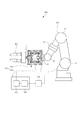
以下の説明では、磁電変換素子を代表してホール素子を挙げて説明するが、ホール素子以外にMR素子など他の磁電変換素子を用いてももちろん良い。図1は、本発明の第1実施形態に係る力覚センサを組み込んだロボット装置の概略構成を示す模式図である。図1に示すロボット装置900は、多関節(本第1実施形態では、6つの関節J1〜J6)のロボットアーム600と、ロボットアーム600の先端に設けられたエンドエフェクタとしてのロボットハンド800と、を備えている。また、ロボット装置900は、力覚センサ500と、ロボットアーム600及びロボットハンド800の動作を制御するロボットコントローラ700と、を備えている。力覚センサ500は、センサ本体100と、センサ本体100に接続される検出装置400とを有している。センサ本体100は、ロボットアーム600の先端とロボットハンド800との間に介在して配置されている。つまり、ロボットアーム600の先端には、センサ本体100が直接設けられている。そして、ロボットアーム600の先端には、ロボットハンド800がこのセンサ本体100を介して設けられている。
[First Embodiment]
In the following description, a Hall element will be described as a representative of the magnetoelectric conversion element, but other magnetoelectric conversion elements such as MR elements may be used in addition to the Hall element. FIG. 1 is a schematic diagram showing a schematic configuration of a robot apparatus incorporating a force sensor according to a first embodiment of the present invention. A
センサ本体100は、図2(a)に示すように、上端が開放した略箱形状の剛体で形成された枠体としての外枠3と、外枠3の上端の開口を囲うように外枠3にねじ等の固定具7で固定された弾性変形する板状の弾性体2とを備えている。また、センサ本体100は、弾性体2に固定されて外枠3に弾性体2を介して弾性支持された作用部1を備えている。作用部1は、弾性体2の貫通孔を通じて外枠3の内部と外部とに跨って配置されている。そして、作用部1は、作用部1の外枠3の外部に突出した部分に外力が作用することにより、外枠3に対して、互いに直交する3軸(X軸、Y軸、Z軸)の軸方向に変位すると共に各軸まわりに変位する。つまり、作用部1は、外枠3に対して6自由度を有している。なお、作用部1は弾性体2と一体に形成されていてもよい。
As shown in FIG. 2A, the sensor
また、センサ本体100は、図2(a)及び図3に示すように、外枠3の内部に配置された磁石としての永久磁石8を備えている。そして、外枠3の内部であって、外枠3の底部には、永久磁石8を固定するための支柱4が、外枠3と一体に設けられている。そして、永久磁石8は、この支柱4に固定されて、外枠3に一体に固定されている。永久磁石8はNd−Fe−B磁石、Sm−Co磁石、Sm−Fe−N磁石、フェライト磁石に代表されるような磁石である。なお、磁石を永久磁石8としたが、磁性体まわりにコイルを巻き、通電することによって磁力を発生させる電磁石であってもよい。
Moreover, the sensor
センサ本体100は、作用部1に固定され、永久磁石8の一方の磁極面8aに対して間隔をあけて対向して配置された第1のセンサ基板10を備えている。また、センサ本体100は、作用部1に基板連結部材5を介して固定され、永久磁石8の他方の磁極面8bに対して間隔をあけて対向して配置された第2のセンサ基板11を備えている。センサ本体100は、n個(nは2以上の整数、本実施形態ではn=4)の磁電変換素子としてホール素子6a,6b,6c,6d(図2(b)参照)を備えている。ホール素子6a,6b,6c,6dは、第1のセンサ基板10に固定され、永久磁石8の一方の磁極面8aに間隔をあけて対向し、互いに間隔をあけて配置されている。また、センサ本体100は、第2のセンサ基板11に固定され、永久磁石8の他方の磁極面8bに間隔をあけて対向し、互いに間隔をあけて配置されたn個(本実施形態ではn=4)の第2のホール素子9a,9b,9c,9d(図2(c)参照)を備えている。つまり第1及び第2のホール素子は永久磁石8に対して変位可能に作用部1に配置されている。互いに直交する3軸の各軸方向の力成分と各軸のまわりのモーメント成分とを求めるには、4個の第1のホール素子6a〜6d及び4個の第2のホール素子9a〜9dとするのが好ましい。磁電変換素子の個数は、検出したい力及びモーメントの種類に応じて、適宜決めて良い。
The sensor
各第1のホール素子6a,6b,6c,6dは、同一の円周上に等間隔で配置されており、また、各第2のホール素子9a,9b,9c,9dは、同一の円周上に等間隔で配置されている。そして、第1のホール素子6a,6b,6c,6dと第2のホール素子9a,9b,9c,9dとは、永久磁石8を中心とする対称面に対して対称配置されている。
The
このように各ホール素子6a〜6d,9a〜9dを配置したことにより、作用部1が外枠3に対して変位すると、各第1のホール素子6a〜6dが永久磁石8の一方の磁極面8aに対して変位する。また、各第2のホール素子9a〜9dが永久磁石8の他方の磁極面8bに対して変位する。つまり作用部1に外部から力が加わると、各第1のホール素子6a〜6dと各第2のホール素子9a〜9dとが基板連結部材5を介して相対的な位置を保ちながら永久磁石8に対して変位する。
By arranging the
各ホール素子6a〜6d,9a〜9dは、当該ホール素子に供給された電流、及び当該ホール素子を交差した磁束に比例した値のホール電圧(出力電圧)を出力する。各ホール素子6a〜6d,9a〜9dは、同一規格のものを使用しており、特性が互いに略同一である。
Each
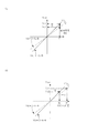
以上の構成により、本実施の形態のセンサ本体100を用いることで、作用部1に作用する、互いに直交する3軸の各軸方向の力成分と各軸のまわりのモーメント成分とを求めることができる。以下、各力成分と各モーメント成分の算出方法について、図4を参照しながら説明する。図4は、センサ本体100の断面模式図であり、図4(a)は作用部1にX軸方向に力Fxを受けた場合、図4(b)はZ軸方向に力Fzを受けた場合、図4(c)はY軸まわりにモーメントMyを受けた場合を示している。
With the above configuration, by using the sensor
図4(a)に示すように、X軸方向の力Fxによってホール素子6aに磁束密度変位量−ΔBxが生じたとすると、ホール素子6b、9a、9bにはそれぞれ磁束密度の変位量がΔBx、−ΔBx、ΔBx生じることになる。
As shown in FIG. 4A, if the magnetic flux density displacement amount -ΔBx is generated in the
また、図4(b)に示すように、Z軸方向の力Fzによってホール素子6aに磁束密度変位量−ΔBzが生じたとすると、ホール素子6b、9a、9bにはそれぞれ磁束密度の変位量が−ΔBz、ΔBz、ΔBz生じることになる。
As shown in FIG. 4B, if the magnetic flux density displacement amount -ΔBz is generated in the
さらに、図4(c)に示すように、Y軸方向のモーメントMyによってホール素子6aに磁束密度変位量ΔByが生じたとすると、ホール素子6b、9a、9bにはそれぞれ磁束密度の変位量が−ΔBy、−ΔBy、ΔBy生じることになる。
Further, as shown in FIG. 4C, if a magnetic flux density displacement amount ΔBy is generated in the
ホール素子6aに生じる磁束密度変位総量ΔB6a、ホール素子6bに生じる磁束密度変位総量ΔB6b、ホール素子9aに生じる磁束密度変位総量ΔB9a、ホール素子9bに生じる磁束密度変位総量ΔB9bとする。
A total magnetic flux density displacement amount ΔB6a generated in the
各磁束密度変位総量は、以下の式となる。
ΔB6a=−ΔBx−ΔBz+ΔBy
ΔB6b=ΔBx−ΔBz−ΔBy
ΔB9a=−ΔBx+ΔBz−ΔBy
ΔB9b=ΔBx+ΔBz+ΔBy
Each magnetic flux density displacement total amount is represented by the following equation.
ΔB6a = −ΔBx−ΔBz + ΔBy
ΔB6b = ΔBx−ΔBz−ΔBy
ΔB9a = −ΔBx + ΔBz−ΔBy
ΔB9b = ΔBx + ΔBz + ΔBy
次に、各々の軸において相対関係にあるホール素子のペアを作り、差分をとる。ここで、kx、kz、kyは磁束密度変位量から力、モーメントに算出するための比例係数である。
Fx
=(ΔB6b+ΔB9b)−(ΔB6a+ΔB9a)
=kx×ΔBx
Fz
=(ΔB9a+ΔB9b)−(ΔB6a+ΔB6b)
=kz×ΔBz
My
=(ΔB6a+ΔB9b)−(ΔB9a+ΔB6b)
=ky×ΔBy
Next, a pair of Hall elements having a relative relationship in each axis is created, and a difference is obtained. Here, kx, kz, and ky are proportional coefficients for calculating force and moment from the magnetic flux density displacement amount.
Fx
= (ΔB6b + ΔB9b) − (ΔB6a + ΔB9a)
= Kx × ΔBx
Fz
= (ΔB9a + ΔB9b) − (ΔB6a + ΔB6b)
= Kz × ΔBz
My
= (ΔB6a + ΔB9b) − (ΔB9a + ΔB6b)
= Ky × ΔBy
同様にして、Y軸方向の力Fy、X軸方向のモーメントMx、Z軸方向のモーメントMzも算出できる。以上のようにして、各軸に独立に力を加えた際に生じる磁束密度変位量の項だけになるので、各軸方向に生じた力成分、及び各軸まわりに生じたモーメント成分を容易に算出できる。本実施の形態では、ホール素子6a〜6d,9a〜9dを用いているので、各ホール素子のホール電圧に基づいて力Fx,Fy,Fz及びモーメントMx,My,Mzを求めることができる。
Similarly, the force Fy in the Y-axis direction, the moment Mx in the X-axis direction, and the moment Mz in the Z-axis direction can be calculated. As described above, since only the term of the magnetic flux density displacement amount generated when force is independently applied to each axis, the force component generated in each axis direction and the moment component generated around each axis can be easily obtained. It can be calculated. In the present embodiment, since the
センサ本体100の作用部1及び外枠3のうち一方、本第1実施形態では外枠3は、ロボットアーム600の先端に固定され、他方、本第1実施形態では作用部1は、ロボットハンド800に固定される。なお、外枠3がロボットハンド800に固定され、作用部1がロボットアーム600の先端に固定されてもよい。図1に示す検出装置400は、センサ本体100の各ホール素子6a〜6d,9a〜9dからのホール電圧を検出して出力する回路部200と、作用部1に作用する力及びモーメントを求める処理部300とを備えている。処理部300は、その各力成分出力をロボットコントローラ700に伝達する。ロボットコントローラ700は、各力成分に基づいてロボットアーム600の姿勢を制御する。
One of the
図5に力覚センサ500の回路部200の電気回路図を示す。図5に示すように、回路部200は、4個の第1のホール素子6a〜6dのそれぞれに接続され、各ホール素子6a〜6dに設定電流値の電流を供給する、ホール素子6a〜6dの個数に対応する個数(つまり4個)の第1の定電流源CC1〜CC4を備えている。また、回路部200は、4個の第2のホール素子9a〜9dのそれぞれに接続され、各ホール素子9a〜9dに設定電流値の電流を供給する、ホール素子9a〜9dの個数に対応する個数(つまり4個)の第2の定電流源CC5〜CC8を備えている。
FIG. 5 shows an electric circuit diagram of the
また、回路部200は、4個の第1のホール素子6a〜6dのそれぞれに接続され、各ホール素子6a〜6dのホール電圧の電圧値を検出する、ホール素子6a〜6dの個数に対応する個数(つまり4個)の第1の電圧検出部AMP1〜AMP4を備えている。また、回路部200は、4個の第2のホール素子9a〜9dのそれぞれに接続され、各ホール素子9a〜9dのホール電圧の電圧値を検出する、ホール素子9a〜9dの個数に対応する個数(つまり4個)の第2の電圧検出部AMP5〜AMP8を備えている。
The
なお、定電流源CC1〜CC8は、各ホール素子6a〜6d,9a〜9dに対応して設けられるので、ホール素子6a〜6d,9a〜9dと同じ数の8個である。同様に、電圧検出部AMP1〜AMP8は、各ホール素子6a〜6d,9a〜9dに対応して設けられるので、ホール素子6a〜6d,9a〜9dと同じ数の8個である。
Since the constant current sources CC1 to CC8 are provided corresponding to the
定電流源CC1〜CC8は、ホール素子6a〜6d,9a〜9dに設定された設定電流値となる一定の電流を供給するように動作する。本実施の形態では、定電流源CC1〜CC8は、互いに同一の電流値の電流をホール素子に供給するように構成されている。
The constant current sources CC1 to CC8 operate so as to supply a constant current having a set current value set in the
電圧検出部AMP1〜AMP8は、差動増幅器であり、検出したホール素子6a〜6d,9a〜9dのホール電圧を増幅して、ホール電圧の電圧値に比例した大きさの電圧信号を出力端子OUT1A〜OUT2Dから次段の図1に示す処理部300に出力する。
The voltage detection units AMP1 to AMP8 are differential amplifiers, amplify the detected Hall voltages of the
処理部300は、各電圧検出部AMP1〜AMP8により検出されたホール電圧の電圧値から上述したような演算を行い、作用部1に作用する、互いに直交する3軸の各軸方向の力成分と各軸のまわりのモーメント成分とを求める。
The
以上、外力によって生じるホール素子6a〜6d,9a〜9dのホール電圧から、演算により力及びモーメントを求めたが、一般的に永久磁石8は温度によって発生磁束が変化する。具体的には、永久磁石8は、温度上昇に伴って磁束が低下する負の温度特性を持っている。
As described above, the force and the moment are obtained by calculation from the Hall voltages of the
本実施の形態では、回路部200は、総和演算部を構成する第1の加算器ADD1、第2の加算器ADD2及び差動増幅器DIF−AMPと、調整部としての差動増幅器ERR−AMPとを備えている。第1の加算器ADD1は、各第1の電圧検出部AMP1〜AMP4から出力された電圧信号を加算し、第2の加算器ADD2は、各第2の電圧検出部AMP5〜AMP8から出力された電圧信号を加算する。
In the present embodiment, the
ここで、本実施の形態では、各ホール素子6a〜6d,9a〜9dの一方の表面を永久磁石8に対向するように配置しており、第1のホール素子6a〜6dのホール電圧と、第2のホール素子9a〜9dのホール電圧との正負の極性が異なる。具体的には、第1のホール素子6a〜6dのホール電圧は正の値であり、第2のホール素子9a〜9dのホール電圧は負の値である。したがって、差動増幅器DIF−AMPは、第1の加算器ADD1の出力結果から第2の加算器ADD2の出力結果を減算することで、各電圧検出部AMP1〜AMP8により検出されたホール電圧の電圧値の絶対値の総和の電圧値Vsを求めている。
Here, in the present embodiment, one surface of each of the
なお、第2のホール素子9a〜9dの他方の面を永久磁石8に対向させて配置すれば、各第2のホール素子9a〜9dのホール電圧は正の値となるので、総和演算部として、差動増幅器DIF−AMPの代わりに加算器とすることができる。あるいは、総和演算部として、加算器ADD1,ADD2及び差動増幅器DIF−AMPの代わりに、全ての電圧検出部AMP1〜AMP8の電圧信号を入力して加算する加算器とすることができる。
If the other surfaces of the
以上の加算器ADD1,ADD2及び差動増幅器DIF−AMPの動作により、各ホール電圧の電圧値の絶対値の総和の電圧値Vsが求められる。この電圧値Vsは、第1のホール素子6a〜6dと第2のホール素子9a〜9dにて検出された磁束の総和を示す値である。そして、電圧値Vsは、永久磁石8に対する第1のホール素子6a〜6d及び第2のホール素子9a〜9dの相対的な変位では変動せず、永久磁石8及びホール素子6a〜6d,9a〜9dの特性が変動した場合に変動する。
Through the operations of the adders ADD1 and ADD2 and the differential amplifier DIF-AMP, the voltage value Vs of the sum of absolute values of the voltage values of the Hall voltages is obtained. The voltage value Vs is a value indicating the total sum of magnetic fluxes detected by the
例えば、作用部1にX軸方向の力Fxが作用して各ホール素子6a〜6d,9a〜9dがX軸方向に変位した場合、ホール素子6a,6c,9a,9cを交差する磁束が増加し、ホール電圧が増加する。これに対し、ホール素子6b,6d,9b,9dを交差する磁束が減少し、ホール電圧は上記の増加量と同じ量だけ減少する。そのため、全ホール素子6a〜6d,9a〜9dの総和の電圧値Vsは変動しない。そして、永久磁石8が温度上昇して永久磁石8にて発生する磁束が低下した場合、各ホール素子6a〜6d,9a〜9dにて出力されるホール電圧の電圧値が低下し、総和の電圧値Vsも低下することとなる。
For example, when a force Fx in the X-axis direction acts on the
そこで差動増幅器ERR−AMPは、入力した総和の電圧値Vsと予め定めた基準電圧値REF−Vとの差分に基づき、総和の電圧値Vsを基準電圧値REF−Vにするための設定電流値を示す電流指令信号(I.FB信号)を各定電流源CC1〜CC8に出力する。 Therefore, the differential amplifier ERR-AMP uses a set current for setting the total voltage value Vs to the reference voltage value REF-V based on the difference between the input total voltage value Vs and a predetermined reference voltage value REF-V. A current command signal (I.FB signal) indicating the value is output to each of the constant current sources CC1 to CC8.
基準電圧値REF−Vは、一定の値であり、総和の電圧値Vsが一定の電圧値に保持されることで、各ホール素子6a〜6d,9a〜9dは、永久磁石8の磁束変動がなかったときと同じホール電圧を出力することとなる。
The reference voltage value REF-V is a constant value, and the total voltage value Vs is held at a constant voltage value, so that each
各定電流源CC1〜CC8は、入力したI.FB信号に対応する設定電流値の電流をそれぞれのホール素子6a〜6d,9a〜9dに供給する。各定電流源CC1〜CC8に出力されるI.FB信号は同一値であり、各ホール素子6a〜6d,9a〜9dには同一値の電流が供給される。
Each of the constant current sources CC1 to CC8 has an input I.D. A current having a set current value corresponding to the FB signal is supplied to each of the
以下、フィードバック動作により各定電流源CC1〜CC8の設定電流値の補正動作について図6及び図7を参照しながら具体的に説明する。 Hereinafter, the correction operation of the set current value of each of the constant current sources CC1 to CC8 by the feedback operation will be specifically described with reference to FIGS.
1.永久磁石8の温度特性補正
永久磁石8の温度特性による補正動作について図6を用いて説明する。図6では、永久磁石8の当初の磁束密度がBであったが、温度上昇により永久磁石8の磁束密度がB’に変動した場合を例としている。
1. Correction of Temperature Characteristics of Permanent Magnet 8 A correction operation based on the temperature characteristics of the
一般的なホール素子の出力電圧(ホール電圧)Vhは下記で表されている。
Vh=K・Ih・B
(Vh:ホール電圧、K:感度係数、Ih:動作電流、B:磁束密度)
The output voltage (Hall voltage) Vh of a general Hall element is expressed as follows.
Vh = K ・ Ih ・ B
(Vh: Hall voltage, K: sensitivity coefficient, Ih: operating current, B: magnetic flux density)
図6(a)に示すように、当初の動作点であった磁束密度Bにおける全てのホール素子のホール電圧の電圧値の総和の電圧値は、
Vo=K・I1・B・・・(1)
となる。
As shown in FIG. 6A, the voltage value of the sum of the voltage values of the Hall voltages of all the Hall elements at the magnetic flux density B, which was the initial operating point, is
Vo = K · I1 · B (1)
It becomes.
また温度上昇により磁石の動作点がB’に移動した場合の総和の電圧値は、
Vo’=K・I1・B’・・・(2)
となる。つまり、図5に示す回路構成では、差動増幅器DIF−AMPの出力電圧VsがVo及びVo’となる。
The total voltage value when the operating point of the magnet moves to B ′ due to temperature rise is
Vo ′ = K · I1 · B ′ (2)
It becomes. That is, in the circuit configuration shown in FIG. 5, the output voltage Vs of the differential amplifier DIF-AMP is Vo and Vo ′.
総磁束検出結果であるVsがVoの場合は、基準電圧値REF−Vと等しいため、差動増幅器ERR−AMPは補正電圧を発生しない。しかし、熱減磁により総磁束が低下したときの総磁束検出結果であるVsがVo’の場合、差動増幅器ERR−AMPは、電圧値Vo’と基準電圧値REF−Vとの差分をVo’に加算して得られる誤差制御電圧Vo”を発生させるためのI・FB信号を出力する。この誤差制御電圧Vo”は、誤差電圧に反比例して発生する。そのため、差動増幅器ERR−AMPは、ホール素子の電流を増加させる方向に調整するI・FB信号を出力する。 When Vs as the total magnetic flux detection result is Vo, the differential amplifier ERR-AMP does not generate a correction voltage because it is equal to the reference voltage value REF-V. However, when Vs, which is the total magnetic flux detection result when the total magnetic flux is reduced due to thermal demagnetization, is Vo ′, the differential amplifier ERR-AMP calculates the difference between the voltage value Vo ′ and the reference voltage value REF-V as Vo. An I · FB signal for generating an error control voltage Vo ″ obtained by adding to 'is output. This error control voltage Vo ″ is generated in inverse proportion to the error voltage. Therefore, the differential amplifier ERR-AMP outputs an I · FB signal that adjusts in a direction to increase the current of the Hall element.

図6(b)に、磁束密度Bの低下を受けてI・FB信号が定電流源CC1〜CC8に出力されて、定電流源CC1〜CC8の電流値がI2に増加する過程が示されている。 FIG. 6B shows a process in which the I / FB signal is output to the constant current sources CC1 to CC8 in response to the decrease in the magnetic flux density B, and the current values of the constant current sources CC1 to CC8 increase to I2. Yes.
このとき、図5に示した回路構成では、差動増幅器ERR−AMPの動作により、総和の電圧値Vsと基準電圧値REF−Vとの誤差電圧が減少するように定電流源CC1〜CC8の電流が制御されるため、誤差制御電圧Vo”は基準電圧値REF−Vと等しくなる。
Vo”≒REF−V≒Vo・・・(4)
このためI2としては、
At this time, in the circuit configuration shown in FIG. 5, the operation of the differential amplifier ERR-AMP causes the constant current sources CC1 to CC8 to decrease so that the error voltage between the total voltage value Vs and the reference voltage value REF-V decreases. Since the current is controlled, the error control voltage Vo ″ is equal to the reference voltage value REF−V.
Vo ”≈REF−V≈Vo (4)
For this reason, as I2,
そして、永久磁石8の動作点がB’点に変化したときのホール電圧Vh2としては、
Vh2=K・I2・B’・・・(6)
であり、式(5)を代入することで、
As the Hall voltage Vh2 when the operating point of the
Vh2 = K · I2 · B '(6)
By substituting equation (5),
つまり、磁束密度がBからB’に低下した場合には、検出される総和の電圧値Vsは、基準電圧値REF−Vと等しい値である電圧値Voから電圧値Vo’に低下する。したがって、差動増幅器ERR−AMPは、総和の電圧値Vsが、基準電圧値REF−Vとなるように定電流源CC1〜CC8の電流値をI1からI2に上昇させるI・FB信号を出力する。これにより、総和の電圧値Vsは、Vo’からVo’’(≒REF−V≒Vo)に上昇し、基準電圧値REF−Vに一定となるように制御される。 That is, when the magnetic flux density decreases from B to B ′, the detected total voltage value Vs decreases from the voltage value Vo that is equal to the reference voltage value REF−V to the voltage value Vo ′. Therefore, the differential amplifier ERR-AMP outputs an I · FB signal for increasing the current value of the constant current sources CC1 to CC8 from I1 to I2 so that the total voltage value Vs becomes the reference voltage value REF-V. . As a result, the total voltage value Vs is controlled to increase from Vo ′ to Vo ″ (≈REF−V≈Vo) and to be constant to the reference voltage value REF−V.
よって、差動増幅器ERR−AMPのフィードバック動作により、総和の電圧値Vsが基準電圧値REF−Vとなるように、各定電流源CC1〜CC8の設定電流値が調整される。そして、この総和の電圧値Vsが基準電圧値REF−Vとなるように、差動増幅器ERR−AMPにより各ホール素子6a〜6d,9a〜9dに電流を供給する定電流源CC1〜CC8の設定電流値が調整されるので、総和の電圧値Vsが一定に保たれる。
Therefore, the set current values of the constant current sources CC1 to CC8 are adjusted by the feedback operation of the differential amplifier ERR-AMP so that the total voltage value Vs becomes the reference voltage value REF-V. The constant current sources CC1 to CC8 that supply current to the
2.感度係数の補正
一般にホール素子は、感度係数(ホール係数)Kにも温度依存性を持っており、環境温度や素子発熱により同じ磁束密度Bであっても出力電圧(ホール電圧)が変動する。ホール素子以外の磁電変換素子も一般には感度係数Kに温度依存性を持っているが、説明が重複するため以下ではホール素子を代表して説明する。
2. Correction of Sensitivity Coefficient In general, a Hall element has a temperature dependency on a sensitivity coefficient (Hall coefficient) K, and the output voltage (Hall voltage) varies even at the same magnetic flux density B due to environmental temperature and element heat generation. Magnetoelectric conversion elements other than Hall elements generally have temperature dependence on the sensitivity coefficient K. However, since the description is duplicated, the Hall elements will be described below as a representative.
ホール素子6a〜6d,9a〜9dの感度係数Kの温度変動による補正動作について図6を用いて説明する。図7では、当初の感度係数がK1であったが、温度上昇により感度係数がK2に変動した場合を例としている。
A correction operation based on a temperature variation of the sensitivity coefficient K of the
図7(a)での当初の動作点であった磁束密度B点でのホール素子のホール電圧の電圧値の総和の電圧値としては、
Vo1=K1・I1・B・・・(8)
となる。
As the voltage value of the sum of the voltage values of the Hall voltage of the Hall element at the magnetic flux density point B, which was the initial operating point in FIG.
Vo1 = K1, I1, B (8)
It becomes.
また温度上昇によりホール素子の感度係数がK2に変動した場合のホール電圧の電圧値の総和の電圧値は、
Vo2=K2・I1・B・・・(9)
となる。つまり、図5に示す回路構成では、差動増幅器DIF−AMPの出力電圧VsがVo1及びVo2となる。
The total voltage value of the Hall voltage when the Hall element sensitivity coefficient changes to K2 due to temperature rise is:
Vo2 = K2, I1, B (9)
It becomes. That is, in the circuit configuration shown in FIG. 5, the output voltage Vs of the differential amplifier DIF-AMP is Vo1 and Vo2.
総磁束検出結果であるVsがVo1の場合は、基準電圧値REF−Vと等しいため、差動増幅器ERR−AMPは補正電圧を発生しない。しかし、ホール素子の感度係数がK2になり、検出されるホール電圧が低下したときの総磁束検出結果であるVsがVo2のときは、差動増幅器ERR−AMPは、以下のように動作する。即ち、差動増幅器ERR−AMPは、電圧値Vo2と基準電圧値REF−Vとの差分をVo2に加算して得られる誤差制御電圧Vo3を発生させるためのI/FB信号を出力する。この誤差制御電圧Vo3は、誤差電圧に反比例して発生する。そのため、差動増幅器ERR−AMPは、ホール素子の電流を増加させる方向に調整するI・FB信号を出力する。 When Vs which is the total magnetic flux detection result is Vo1, since it is equal to the reference voltage value REF-V, the differential amplifier ERR-AMP does not generate a correction voltage. However, when the sensitivity coefficient of the Hall element is K2 and Vs, which is the total magnetic flux detection result when the detected Hall voltage is reduced, is Vo2, the differential amplifier ERR-AMP operates as follows. That is, the differential amplifier ERR-AMP outputs an I / FB signal for generating an error control voltage Vo3 obtained by adding the difference between the voltage value Vo2 and the reference voltage value REF-V to Vo2. This error control voltage Vo3 is generated in inverse proportion to the error voltage. Therefore, the differential amplifier ERR-AMP outputs an I · FB signal that adjusts in a direction to increase the current of the Hall element.
図7(b)に、ホール素子の感度係数がK2になり、検出されるホール電圧の低下を受けて、I・FB信号が定電流源CC1〜CC8に出力されて、定電流源CC1〜CC8の電流値がI3に増加する過程が示されている。 In FIG. 7B, the sensitivity coefficient of the Hall element becomes K2, and when the detected Hall voltage is lowered, the I · FB signal is output to the constant current sources CC1 to CC8, and the constant current sources CC1 to CC8. The process of increasing the current value of I3 to I3 is shown.
このとき、図5に示した回路構成では、差動増幅器ERR−AMPの動作により、総和の電圧値Vsと基準電圧値REF−Vとの誤差電圧が減少するように定電流源CC1〜CC8の電流が制御されるため、誤差制御電圧Vo3は基準電圧値REF−Vと等しくなる。
Vo3≒REF−V≒Vo・・・(11)
このためI3としては、
At this time, in the circuit configuration shown in FIG. 5, the operation of the differential amplifier ERR-AMP causes the constant current sources CC1 to CC8 to decrease so that the error voltage between the total voltage value Vs and the reference voltage value REF-V decreases. Since the current is controlled, the error control voltage Vo3 becomes equal to the reference voltage value REF-V.
Vo3≈REF−V≈Vo (11)
For this reason, as I3,
そして、ホール素子の感度係数がK2点に変化したときのホール電圧Vh3としては、
Vh3=K2・I3・B・・・(13)
であり、式(12)を代入することで、
And, as the Hall voltage Vh3 when the sensitivity coefficient of the Hall element changes to the K2 point,
Vh3 = K2, I3, B (13)
By substituting equation (12),
つまり、ホール素子の感度係数がK1からK2に低下した場合には、検出される総和の電圧値Vsは、基準電圧値REF−Vと等しい値である電圧値Vo1から電圧値Vo2に低下する。したがって、差動増幅器ERR−AMPは、総和の電圧値Vsが、基準電圧値REF−Vとなるように定電流源CC1〜CC8の電流値をI1からI3に上昇させるI・FB信号を出力する。これにより、総和の電圧値Vsは、Vo2からVo3(≒REF−V≒Vo)に上昇し、基準電圧値REF−Vに一定となるように制御される。 That is, when the sensitivity coefficient of the Hall element decreases from K1 to K2, the detected total voltage value Vs decreases from the voltage value Vo1 that is equal to the reference voltage value REF-V to the voltage value Vo2. Therefore, the differential amplifier ERR-AMP outputs an I · FB signal that increases the current values of the constant current sources CC1 to CC8 from I1 to I3 so that the total voltage value Vs becomes the reference voltage value REF-V. . As a result, the total voltage value Vs increases from Vo2 to Vo3 (≈REF−V≈Vo) and is controlled to be constant at the reference voltage value REF−V.
よって、差動増幅器ERR−AMPのフィードバック動作により、総和の電圧値Vsが基準電圧値REF−Vとなるように、各定電流源CC1〜CC8の設定電流値が調整される。そして、この総和の電圧値Vsが基準電圧値REF−Vとなるように、差動増幅器ERR−AMPにより各ホール素子6a〜6d,9a〜9dに電流を供給する定電流源CC1〜CC8の設定電流値が調整されるので、総和の電圧値Vsが一定に保たれる。
Therefore, the set current values of the constant current sources CC1 to CC8 are adjusted by the feedback operation of the differential amplifier ERR-AMP so that the total voltage value Vs becomes the reference voltage value REF-V. The constant current sources CC1 to CC8 that supply current to the
以上の動作により、永久磁石8の磁束及び各ホール素子6a〜6d,9a〜9dの検出感度が温度変化や経年変化等により変動しても、各ホール素子6a〜6d,9a〜9dの出力電圧は温度変化や経年変化等に依存しない安定したものとなる。このように、温度変化や経年変化等により永久磁石8及びホール素子6a〜6d,9a〜9dの両方の特性が変動したとしても、温度センサを用いない簡易な構成で、ホール素子6a〜6d,9a〜9dの出力電圧を補正することができる。よって、力及びモーメントの検出精度が向上させたロボット装置が実現できる。
With the above operation, even if the magnetic flux of the
[第2実施形態]
次に、本発明の第2実施形態に係る力覚センサについて説明する。図8は、本発明の第2実施形態に係る力覚センサのセンサ本体を示す断面模式図である。なお、本第2実施形態において、上記第1実施形態と同様の構成については、同一符号を付して説明を省略する。
[Second Embodiment]
Next, a force sensor according to a second embodiment of the present invention will be described. FIG. 8 is a schematic cross-sectional view showing a sensor body of a force sensor according to the second embodiment of the present invention. Note that in the second embodiment, the same components as those in the first embodiment are denoted by the same reference numerals, and description thereof is omitted.
上記第1実施形態の力覚センサ500では、作用部1と共にホール素子6a〜6d,9a〜9dが永久磁石8に対して変位する場合について説明した。図8に示す本第2実施形態の力覚センサ500Aでは、作用部1と共に永久磁石8がホール素子6a〜6d,9a〜9dに対して変位する。
In the
具体的には、ホール素子6a〜6dが固定された第1のセンサ基板10が基板連結部材5を介して外枠3に固定され、ホール素子9a〜9dが固定された第2のセンサ基板11が外枠3に固定されている。そして、永久磁石8が支柱4Aを介して作用部1に固定されている。これにより、永久磁石8は、作用部1に一体に固定されているので、作用部1の変位により、ホール素子6a〜6d,9a〜9dに対して変位する。
Specifically, the
このように構成することで、第1のホール素子6a〜6dは、作用部1の変位により一方の磁極面8aに対して相対的に変位し、第2のホール素子9a〜9dは、作用部1の変位により他方の磁極面8bに対して相対的に変位する。
With this configuration, the
以上本第2実施形態では、永久磁石8の磁束及び各ホール素子6a〜6d,9a〜9dの検出感度が温度変化や経年変化等により変動しても、各ホール素子6a〜6d,9a〜9dの出力電圧は温度変化や経年変化等に依存しない安定したものとなる。このように、温度変化や経年変化等により永久磁石8及びホール素子6a〜6d,9a〜9dの両方の特性が変動したとしても、温度センサを用いない簡易な構成で、ホール素子6a〜6d,9a〜9dの出力電圧を補正することができる。よって、力及びモーメントの検出精度が向上する。
As described above, in the second embodiment, even if the magnetic flux of the
また、センサ基板10,11を外枠3に固定するようにしたので、組み立てが容易となる。つまり外枠3に固定された第1の磁電変換素子と、互いの相対位置を保って外枠3に固定された第2の磁電変換素子が配置されていれば良い。また、外枠3に段付き加工をすることで、基板保持用の基板連結部材5が不要とする構成も実現できる。
Further, since the
[第3実施形態]
次に、本発明の第3実施形態に係る力覚センサについて説明する。図9は、本発明の第3実施形態に係る力覚センサを組み込んだロボット装置の概略構成を示す模式図である。なお、本第3実施形態において、上記第1実施形態と同様の構成については、同一符号を付して説明を省略する。
[Third Embodiment]
Next, a force sensor according to a third embodiment of the present invention will be described. FIG. 9 is a schematic diagram showing a schematic configuration of a robot apparatus incorporating a force sensor according to the third embodiment of the present invention. Note that, in the third embodiment, the same components as those in the first embodiment are denoted by the same reference numerals, and description thereof is omitted.
図9に示すロボット装置900Bは、多関節(本第3実施形態では、6つの関節J1〜J6)のロボットアーム600と、ロボットアーム600の先端に設けられたエンドエフェクタとしてのロボットハンド800と、を備えている。また、ロボット装置900Bは、力覚センサ500Bと、ロボットアーム600及びロボットハンド800の動作を制御するロボットコントローラ700と、を備えている。力覚センサ500Bは、センサ本体100Bと、センサ本体100Bに接続される検出装置400Bとを有している。センサ本体100Bは、ロボットアーム600の先端とロボットハンド800との間に介在して配置されている。つまり、ロボットアーム600の先端には、センサ本体100Bが直接設けられている。そして、ロボットアーム600の先端には、ロボットハンド800がこのセンサ本体100Bを介して設けられている。
A
上記第1実施形態では、第1のホール素子の個数と、第2のホール素子の個数とを同一とした場合について説明した。本第3実施形態では、図10に示すように、センサ本体100Bは、n個(本第3実施形態ではn=4、即ち4個)の第1のホール素子6a〜6dと、1個の第2のホール素子12とを備えている。
In the first embodiment, the case where the number of first Hall elements is the same as the number of second Hall elements has been described. In the third embodiment, as shown in FIG. 10, the
また、上記第1実施形態のセンサ本体100では、作用部1と共にホール素子6a〜6d,9a〜9dが永久磁石8に対して変位する場合について説明した。図9及び図10に示す本第3実施形態の力覚センサ500Bのセンサ本体100Bでは、作用部1と共に永久磁石8がホール素子6a〜6d,12に対して変位する。
In the sensor
具体的には、第1のホール素子6a〜6dが固定された第1のセンサ基板10は、第1のホール素子6a〜6dが永久磁石8の一方の磁極面8aに対向するように、基板連結部材5を介して外枠3に固定されている。第2のホール素子12が固定された第2のセンサ基板13は、第2のホール素子12が永久磁石8の他方の磁極面8bに対向するように、外枠3に固定されている。そして、永久磁石8が支柱4Aを介して作用部1に固定されている。これにより、永久磁石8は、作用部1に一体に固定されているので、作用部1の変位により、ホール素子6a〜6d,12に対して変位する。
Specifically, the
このように構成することで、第1のホール素子6a〜6dは、作用部1の変位により一方の磁極面8aに対して相対的に変位し、第2のホール素子12は、作用部1の変位により他方の磁極面8bに対して相対的に変位する。
With this configuration, the
図9に示すように、センサ本体100Bの作用部1及び外枠3のうち一方、本第3実施形態では外枠3は、ロボットアーム600の先端に固定され、他方、本第3実施形態では作用部1は、ロボットハンド800に固定される。なお、外枠3がロボットハンド800に固定され、作用部1がロボットアーム600の先端に固定されてもよい。図9に示す検出装置400Bは、センサ本体100Bの各ホール素子6a〜6d,12からのホール電圧を検出して出力する回路部200Bと、作用部1に作用する力及びモーメントを求める処理部300Bとを備えている。処理部300Bは、その各力成分出力をロボットコントローラ700に伝達する。ロボットコントローラ700は、各力成分に基づいてロボットアーム600の姿勢を制御する。
As shown in FIG. 9, one of the
図11は、本第3実施形態に係る力覚センサ500Bの回路部200Bを示す電気回路図である。回路部200Bは、4個の第1のホール素子6a〜6dのそれぞれに接続され、各第1のホール素子6a〜6dに設定電流値の電流を供給する、ホール素子6a〜6dの個数に対応する個数(4個)の第1の定電流源CC1〜CC4を備えている。また、回路部200Bは、第2のホール素子12に接続され、第2のホール素子12に設定電流値の電流を供給する第2の定電流源CC5を備えている。
FIG. 11 is an electric circuit diagram showing the
さらに、回路部200Bは、4個の第1のホール素子6a〜6dのそれぞれに接続され、各第1のホール素子6a〜6dのホール電圧の電圧値を検出する、ホール素子6a〜6dの個数に対応する個数(4個)の第1の電圧検出部AMP1〜AMP4を備えている。また、回路部200Bは、第2のホール素子12に接続され、第2のホール素子12のホール電圧の電圧値を検出する第2の電圧検出部AMP5を備えている。
Furthermore, the
さらにまた、回路部200Bは、総和演算部として、加算器ADD1、増幅器REF−AMP及び差動増幅器DIF−AMPと、調整部として差動増幅器ERR−AMPとを備えている。
Furthermore, the
加算器ADD1は、各第1の電圧検出部AMP1〜AMP4から出力された電圧信号を加算する。増幅器REF−AMPは、第2の電圧検出部AMP5により検出されたホール電圧の電圧値のn倍(4倍)の電圧値を示す電圧信号を出力する。これにより、第2の電圧検出部AMP5による出力レベルが、加算器ADD1の出力レベルにほぼ合わせられる。 The adder ADD1 adds the voltage signals output from the first voltage detection units AMP1 to AMP4. The amplifier REF-AMP outputs a voltage signal indicating a voltage value that is n times (four times) the voltage value of the Hall voltage detected by the second voltage detection unit AMP5. As a result, the output level of the second voltage detector AMP5 is substantially matched to the output level of the adder ADD1.
差動増幅器DIF−AMPは、加算器ADD1の出力結果から増幅器REF−AMPの出力結果を引いている。これにより、差動増幅器DIF−AMPは、各第1の電圧検出部AMP1〜4により検出されたホール電圧の電圧値の絶対値と、第2の電圧検出部AMP5により検出されたホール電圧の電圧値の4倍の電圧値の絶対値との総和の電圧値Vsを求めている。 The differential amplifier DIF-AMP subtracts the output result of the amplifier REF-AMP from the output result of the adder ADD1. Thereby, the differential amplifier DIF-AMP has the absolute value of the voltage value of the Hall voltage detected by each of the first voltage detection units AMP1 to 4 and the voltage of the Hall voltage detected by the second voltage detection unit AMP5. The total voltage value Vs with the absolute value of the voltage value four times the value is obtained.
差動増幅器ERR−AMPは、上記第1実施形態と同様に、総和の電圧値Vsと基準電圧値REF−Vとを比較し、総和の電圧値Vsが基準電圧値REF−Vとなるように、各定電流源CC1〜CC5の電流値を調整する。 Similarly to the first embodiment, the differential amplifier ERR-AMP compares the total voltage value Vs with the reference voltage value REF-V so that the total voltage value Vs becomes the reference voltage value REF-V. The current values of the constant current sources CC1 to CC5 are adjusted.
以上、本第3実施形態では、永久磁石8の磁束及び各ホール素子6a〜6d,12の検出感度が温度変化や経年変化等により変動しても、各ホール素子6a〜6d,12の出力電圧は温度変化や経年変化等に依存しない安定したものとなる。このように、温度変化や経年変化等により永久磁石8及びホール素子6a〜6d,12の両方の特性が変動したとしても、温度センサを用いない簡易な構成で、ホール素子6a〜6d,12の出力電圧を補正することができる。よって、力及びモーメントの検出精度が向上する。また、第2のホール素子12を1個としたことで、第2の定電流源CC5、第2の電圧検出部AMP5も1個でよい。従って、上記第1実施形態の力覚センサよりもコストを削減することができる。更に、センサ基板10,13を外枠3に固定するようにしたので、組み立てが容易となる。また、外枠3に段付き加工をすることで、基板保持用の基板連結部材5が不要とする構成の力覚センサを組み込んだロボット装置が実現できる。
As described above, in the third embodiment, even if the magnetic flux of the
[第4実施形態]
次に、本発明の第4実施形態に係る力覚センサについて説明する。図12は、本発明の第4実施形態に係る力覚センサのセンサ本体を示す断面模式図である。なお、本第4実施形態において、上記第1〜第3実施形態と同様の構成については、同一符号を付して説明を省略する。
[Fourth Embodiment]
Next, a force sensor according to a fourth embodiment of the present invention will be described. FIG. 12 is a schematic cross-sectional view showing a sensor body of a force sensor according to the fourth embodiment of the present invention. Note that in the fourth embodiment, identical symbols are assigned to configurations similar to those in the first through third embodiments and descriptions thereof are omitted.
図12に示す力覚センサのセンサ本体100Cは、n個(本第4実施形態ではn=4、即ち4個)の第1のホール素子6a〜6dと、1個の第2のホール素子12とを備えている。第1のホール素子6a〜6dが固定された第1のセンサ基板10は、第1のホール素子6a〜6dが永久磁石8の一方の磁極面8aに対向するように、基板連結部材5を介して作用部1に固定されている。第2のホール素子12が固定された第2のセンサ基板13は、第2のホール素子12が永久磁石8の他方の磁極面8bに対向するように、作用部1に固定されている。これにより、ホール素子6a〜6d,12は、作用部1の変位により、外枠3に一体に固定された永久磁石8に対して変位する。以上の構成により、本第4実施形態では、上記第3実施形態と同様の効果を奏する。
The
[第5実施形態]
次に、本発明の第5実施形態に係る力覚センサを組み込んだロボットハンドについて説明する。図13は、本発明の第5実施形態に係る力覚センサを組み込んだロボットハンドを有するロボット装置の概略構成を示す模式図である。なお、本第5実施形態において、上記第1〜4実施形態と同様の構成については、同一符号を付して説明を省略する。
[Fifth Embodiment]
Next, a robot hand incorporating a force sensor according to a fifth embodiment of the invention will be described. FIG. 13 is a schematic diagram showing a schematic configuration of a robot apparatus having a robot hand incorporating a force sensor according to a fifth embodiment of the present invention. Note that in the present fifth embodiment, identical symbols are assigned to configurations similar to those in the first through fourth embodiments and descriptions thereof are omitted.
図13に示すロボットハンド800Dは、ハンド本体801と、ハンド本体801に開閉可能に支持される複数(本実施形態では2つ)のフィンガー802,803と、を備えている。フィンガー803は、ハンド本体801に支持される基端部803aと、基端部803aから延びる先端部803bとを有している。
A
ロボットハンド800Dは、上記第1〜第4実施形態のうちいずれの力覚センサを備えていてもよいが、本第5実施形態では、上記第3実施形態と同様の力覚センサを備えている。この力覚センサのセンサ本体100Bは、基端部803aと先端部803bとの間に介在して配置されている。そして、外枠3及び作用部1のうち、一方、本第5実施形態では外枠3が、基端部803aに固定されている。また、外枠3及び作用部1のうち、他方、本第5実施形態では作用部1が、先端部803bに固定されている。
The
なお、外枠3が先端部803bに固定され、作用部1が基端部803aに固定されていてもよい。また、フィンガー802にセンサ本体100Bを設けてもよい。
The
本第5実施形態では、上記第3実施形態と同様の効果を奏する。また、外枠3に段付き加工をすることで、基板保持用の基板連結部材5が不要とする構成が可能なロボットハンドを用いたロボット装置を実現できる。
The fifth embodiment has the same effects as those of the third embodiment. Further, by performing stepped processing on the
なお、上記第1〜第5実施形態に基づいて本発明を説明したが、本発明はこれに限定するものではない。上記第1,第2実施形態では、力覚センサが第1のホール素子を4個、第2のホール素子を4個備え、3軸の各軸方向の力成分及び3軸の各軸まわりのモーメント成分を求める場合について説明したが、これに限定するものではない。第1及び第2のホール素子の個数は、2個以上であればよい。そして、力及びモーメントの少なくとも一方を求めるようにすればよく、例えば力のみ又はモーメントのみを求めるようにしてロボット装置を制御してもよい。 In addition, although this invention was demonstrated based on the said 1st-5th embodiment, this invention is not limited to this. In the first and second embodiments, the force sensor includes four first Hall elements and four second Hall elements, and the force component in each of the three axes and the three axes around each axis. Although the case of obtaining the moment component has been described, the present invention is not limited to this. The number of first and second Hall elements may be two or more. Then, at least one of force and moment may be obtained. For example, the robot apparatus may be controlled so as to obtain only force or moment.
また、上記第3,第4実施形態では、力覚センサが第1のホール素子を4個備え、3軸の各軸方向の力成分及び3軸の各軸まわりのモーメント成分を求める場合について説明したが、これに限定するものではない。第1のホール素子の個数は、2個以上であればよい。そして、力及びモーメントの少なくとも一方を求めるようにすればよく、例えば力のみ又はモーメントのみを求めるようにしてロボット装置を制御してもよい。 In the third and fourth embodiments described above, the force sensor has four first Hall elements, and the force component in each of the three axes and the moment component around each of the three axes are obtained. However, the present invention is not limited to this. The number of first Hall elements may be two or more. Then, at least one of force and moment may be obtained. For example, the robot apparatus may be controlled so as to obtain only force or moment.
上記第5実施形態のロボットハンドでは、力覚センサのセンサ本体を2本のフィンガーのうちの片側にのみセンサ本体を装備しているが、複数本のフィンガーのそれぞれにセンサ本体を装備して、その合計力を基に、ロボット動作を制御しても良い。フィンガーの本数としても2本以上の複数本の構成でよく、力覚センサ実装位置にしてもフィンガーの先端部に組み込んでもよい。 In the robot hand of the fifth embodiment, the sensor body of the force sensor is equipped with the sensor body only on one side of the two fingers, but each of the plurality of fingers is equipped with a sensor body, The robot operation may be controlled based on the total force. The number of fingers may be two or more, and the force sensor mounting position may be incorporated at the tip of the finger.
上記第1〜第4実施形態では、力覚センサの実装位置についても、エンドエフェクタに限定されることはなく、各関節部に必要に応じて組み込んでも良い。 In the first to fourth embodiments, the mounting position of the force sensor is not limited to the end effector, and may be incorporated into each joint as necessary.
上記第1〜第5実施形態では、検出装置がアナログ回路で構成された回路部とコンピュータで構成された処理部とを備え、磁電変換素子の出力をアナログ回路でアナログ処理により演算したが、AD変換してコンピュータでデジタル処理により演算してもよい。 In the first to fifth embodiments, the detection device includes a circuit unit configured with an analog circuit and a processing unit configured with a computer, and the output of the magnetoelectric conversion element is calculated by analog processing with the analog circuit. You may convert and operate by digital processing with a computer.
また、上記第1〜第5実施形態では、磁電変換素子としてホール素子を用いた場合について説明したが、本発明はホール素子以外に、例えばMR素子や、磁気インピーダンス素子、フラックスゲート素子等の他の磁電変換素子を用いた場合についても適用可能である。 In the first to fifth embodiments, the case where the Hall element is used as the magnetoelectric conversion element has been described. However, in addition to the Hall element, the present invention is not limited to the MR element, the magnetic impedance element, the flux gate element, and the like. The present invention can also be applied to the case of using the magnetoelectric conversion element.
1…作用部、2…弾性体、3…外枠(枠体)、6a〜6d…第1のホール素子(第1の磁電変換素子)、8…永久磁石(磁石)、8a…一方の磁極面、8b…他方の磁極面、9a〜9d…第2のホール素子(第2の磁電変換素子)、12…第2のホール素子(第2の磁電変換素子)、100,100A,100B,100C…センサ本体、200,200B…回路部、300…処理部、500…力覚センサ、ADD1,ADD2…加算器(総和演算部)、AMP1〜AMP4…第1の電圧検出部、AMP5〜AMP8…第2の電圧検出部、CC1〜CC8…定電流源、DIF−AMP…差動増幅器(総和演算部)、ERR−AMP…差動増幅器(調整部)、REF−AMP…増幅器(総和演算部)
DESCRIPTION OF
Claims (10)
前記センサ本体に接続される検出装置と、を備え、
前記センサ本体は、
枠体と、
前記枠体に支持され、外力が作用することにより前記枠体に対して変位する作用部と、
前記枠体の内部に配置され、前記枠体に固定された磁石と、
前記磁石の一方の磁極面に対向するように前記作用部に固定され、前記作用部と共に前記一方の磁極面に対して変位可能に配置された第1の磁電変換素子と、
前記磁石の他方の磁極面に対向するように前記作用部に固定され、前記作用部と共に前記他方の磁極面に対して変位可能に配置された第2の磁電変換素子と、を有し、
前記検出装置は、
前記第1の磁電変換素子及び前記第2の磁電変換素子のそれぞれの出力した電圧の電圧値から、前記作用部に作用する力及びモーメントの少なくとも一方を求めるとともに、
前記第1及び第2の磁電変換素子が出力した前記電圧値の絶対値の総和の電圧値を求め、
前記総和の電圧値が予め定めた基準電圧値となるように、前記第1及び第2の磁電変換素子へ供給する電流値を調整することを特徴とする力覚センサ。 A sensor body;
A detection device connected to the sensor body,
The sensor body is
A frame,
An action portion that is supported by the frame body and is displaced with respect to the frame body by an external force acting;
A magnet disposed inside the frame and fixed to the frame;
A first magnetoelectric transducer fixed to the working portion so as to face one magnetic pole surface of the magnet, and disposed so as to be able to be displaced with respect to the one magnetic pole surface together with the working portion;
A second magnetoelectric conversion element fixed to the action portion so as to face the other magnetic pole surface of the magnet, and disposed to be displaceable with the action portion with respect to the other magnetic pole surface,
The detection device includes:
While obtaining at least one of a force and a moment acting on the action part from the voltage values of the voltages outputted from the first magnetoelectric conversion element and the second magnetoelectric conversion element,
Obtaining a voltage value of a sum of absolute values of the voltage values output by the first and second magnetoelectric transducers;
A force sensor for adjusting a current value supplied to the first and second magnetoelectric transducers so that the total voltage value becomes a predetermined reference voltage value.
前記センサ本体に接続される検出装置と、を備え、
前記センサ本体は、
枠体と、
前記枠体に支持され、外力が作用することにより前記枠体に対して変位する作用部と、
前記枠体の内部に配置され、前記作用部に固定されて前記作用部と一体に変位する磁石と、
前記磁石の一方の磁極面に対向するように前記枠体に固定された第1の磁電変換素子と、
前記磁石の他方の磁極面に対向するように、かつ前記枠体に対して前記第1の磁電変換素子と互いの相対位置を保って固定された第2の磁電変換素子と、を有し、
前記検出装置は、
前記第1の磁電変換素子及び前記第2の磁電変換素子のそれぞれの出力した電圧の電圧値から、前記作用部に作用する力及びモーメントの少なくとも一方を求めるとともに、
前記第1及び第2の磁電変換素子が出力した前記電圧値の絶対値の総和の電圧値を求め、
前記総和の電圧値が予め定めた基準電圧値となるように、前記第1及び第2の磁電変換素子へ供給する電流値を調整することを特徴とする力覚センサ。 A sensor body;
A detection device connected to the sensor body,
The sensor body is
A frame,
An action portion that is supported by the frame body and is displaced with respect to the frame body by an external force acting;
A magnet disposed inside the frame, fixed to the action part and displaced integrally with the action part;
A first magnetoelectric conversion element fixed to the frame so as to face one of the magnetic pole surfaces of the magnet;
A second magnetoelectric conversion element fixed so as to oppose the other magnetic pole surface of the magnet and maintaining the relative position of the first magnetoelectric conversion element with respect to the frame,
The detection device includes:
While obtaining at least one of a force and a moment acting on the action part from the voltage values of the voltages outputted from the first magnetoelectric conversion element and the second magnetoelectric conversion element,
Obtaining a voltage value of a sum of absolute values of the voltage values output by the first and second magnetoelectric transducers;
A force sensor for adjusting a current value supplied to the first and second magnetoelectric transducers so that the total voltage value becomes a predetermined reference voltage value.
前記センサ本体に接続される検出装置と、を備え、
前記センサ本体は、
枠体と、
前記枠体に支持され、外力が作用することにより前記枠体に対して変位する作用部と、
前記枠体の内部に配置され、前記枠体に固定された磁石と、
前記磁石の一方の磁極面に対向するように互いに間隔をあけて前記作用部に固定され、前記作用部と共に前記一方の磁極面に対して変位可能に配置されたn個(nは2以上の整数)の第1の磁電変換素子と、
前記磁石の他方の磁極面に対向するように前記作用部に固定され、前記作用部と共に前記他方の磁極面に対して変位可能に配置された1個の第2の磁電変換素子と、を有し、
前記検出装置は、
前記n個の第1の磁電変換素子のそれぞれの出力した電圧の電圧値と、前記第2の磁電変換素子の出力した電圧の電圧値とから、前記作用部に作用する力及びモーメントの少なくとも一方を求めるとともに、
前記各第1の磁電変換素子がそれぞれ出力した電圧値の絶対値と、前記第2の磁電変換素子が出力した電圧値のn倍の電圧値の絶対値との総和の電圧値を求め、
前記総和の電圧値が予め定めた基準電圧値となるように、前記第1及び第2の磁電変換素子へ供給する電流値を調整することを特徴とする力覚センサ。 A sensor body;
A detection device connected to the sensor body,
The sensor body is
A frame,
An action portion that is supported by the frame body and is displaced with respect to the frame body by an external force acting;
A magnet disposed inside the frame and fixed to the frame;
N pieces (n is equal to or more than 2) fixed to the action part at a distance from each other so as to face one magnetic pole face of the magnet and displaceable with respect to the one magnetic pole face together with the action part. An integer) first magnetoelectric transducer,
A second magnetoelectric conversion element fixed to the action portion so as to face the other magnetic pole surface of the magnet and disposed so as to be displaceable with the action portion with respect to the other magnetic pole surface; And
The detection device includes:
At least one of the force and the moment acting on the action part from the voltage value of the voltage output from each of the n first magnetoelectric conversion elements and the voltage value of the voltage output from the second magnetoelectric conversion element. As well as
A total voltage value of the absolute value of the voltage value output by each of the first magnetoelectric conversion elements and the absolute value of the voltage value n times the voltage value output by the second magnetoelectric conversion element;
A force sensor for adjusting a current value supplied to the first and second magnetoelectric transducers so that the total voltage value becomes a predetermined reference voltage value.
前記センサ本体が接続される検出装置と、を備え、
前記センサ本体は、
枠体と、
前記枠体に支持され、外力が作用することにより前記枠体に対して変位する作用部と、
前記枠体の内部に配置され、前記作用部に固定されて前記作用部と一体に変位する磁石と、
前記磁石の一方の磁極面に対向するように互いに間隔をあけて前記枠体に固定されたn個(nは2以上の整数)の第1の磁電変換素子と、
前記磁石の他方の磁極面に対向するように、かつ前記枠体に対して前記第1の磁電変換素子と互いの相対位置を保って固定された第2の磁電変換素子と、を有し、
前記検出装置は、
前記n個の第1の磁電変換素子のそれぞれの出力する電圧の電圧値と、前記第2の磁電変換素子の出力する電圧の電圧値とから、前記作用部に作用する力及びモーメントの少なくとも一方を求めるとともに、
前記各第1の磁電変換素子が出力した電圧の電圧値の絶対値と、前記第2の磁電変換素子が出力した電圧の電圧値のn倍の電圧値の絶対値との総和の電圧値を求め、
前記総和の電圧値が予め定めた基準電圧値となるように、前記第1及び第2の磁電変換素子へ供給する電流値を調整することを特徴とする力覚センサ。 A sensor body;
A detection device to which the sensor body is connected,
The sensor body is
A frame,
An action portion that is supported by the frame body and is displaced with respect to the frame body by an external force acting;
A magnet disposed inside the frame, fixed to the action part and displaced integrally with the action part;
N number (n is an integer of 2 or more) of first magnetoelectric transducers fixed to the frame body at intervals so as to face one magnetic pole surface of the magnet;
A second magnetoelectric conversion element fixed so as to oppose the other magnetic pole surface of the magnet and maintaining the relative position of the first magnetoelectric conversion element with respect to the frame,
The detection device includes:
At least one of a force and a moment acting on the action part from the voltage value of the voltage output from each of the n first magnetoelectric conversion elements and the voltage value of the voltage output from the second magnetoelectric conversion element. As well as
The sum of the absolute value of the voltage value of the voltage output from each of the first magnetoelectric conversion elements and the absolute value of the voltage value of n times the voltage value of the voltage output from the second magnetoelectric conversion element is Seeking
A force sensor for adjusting a current value supplied to the first and second magnetoelectric transducers so that the total voltage value becomes a predetermined reference voltage value.
請求項1乃至4のいずれか1項に記載の力覚センサと、を備え、
前記センサ本体が前記ロボットアームに設けられている、
ことを特徴とするロボット装置。 An articulated robot arm,
A force sensor according to any one of claims 1 to 4,
The sensor body is provided on the robot arm;
A robot apparatus characterized by that.
前記ハンド本体に支持されるフィンガーと、
請求項1乃至4のいずれか1項に記載の力覚センサと、を備え、
前記センサ本体が前記フィンガーに設けられている、
ことを特徴とするロボットハンド。 The hand body,
Fingers supported by the hand body;
A force sensor according to any one of claims 1 to 4,
The sensor body is provided on the finger;
Robot hand characterized by that.
前記第1の磁電変換素子及び前記第2の磁電変換素子のそれぞれの出力した電圧の電圧値から、前記作用部に作用する力及びモーメントの少なくとも一方を求めるとともに、
前記第1及び第2の磁電変換素子が出力した前記電圧値の絶対値の総和の電圧値を求め、
前記総和の電圧値が予め定めた基準電圧値となるように、前記第1及び第2の磁電変換素子へ供給する電流値を調整することを特徴とする検出装置。 Opposed to a frame, an action portion supported by the frame and displaced with respect to the frame by an external force, a magnet disposed inside the frame, and one magnetic pole surface of the magnet The first magnetoelectric conversion element fixed to the action part and arranged to be displaceable with the action part with respect to the one magnetic pole face, and the action so as to face the other magnetic pole face of the magnet Of the force and moment that are connected to the sensor body, and are connected to the sensor body, the second magnetoelectric conversion element being fixed to the part and displaceable with the action part with respect to the other magnetic pole surface. A detection device for detecting either one of the following :
While obtaining at least one of a force and a moment acting on the action part from the voltage values of the voltages outputted from the first magnetoelectric conversion element and the second magnetoelectric conversion element,
Obtaining a voltage value of a sum of absolute values of the voltage values output by the first and second magnetoelectric transducers;
A detection apparatus, wherein a current value supplied to the first and second magnetoelectric transducers is adjusted so that the total voltage value becomes a predetermined reference voltage value.
前記第1の磁電変換素子及び前記第2の磁電変換素子のそれぞれの出力した電圧の電圧値から、前記作用部に作用する力及びモーメントの少なくとも一方を求めるとともに、 While obtaining at least one of a force and a moment acting on the action part from the voltage values of the voltages outputted from the first magnetoelectric conversion element and the second magnetoelectric conversion element,
前記第1及び第2の磁電変換素子が出力した前記電圧値の絶対値の総和の電圧値を求め、 Obtaining a voltage value of a sum of absolute values of the voltage values output by the first and second magnetoelectric transducers;
前記総和の電圧値が予め定めた基準電圧値となるように、前記第1及び第2の磁電変換素子へ供給する電流値を調整することを特徴とする検出装置。 A detection apparatus, wherein a current value supplied to the first and second magnetoelectric transducers is adjusted so that the total voltage value becomes a predetermined reference voltage value.
前記n個の第1の磁電変換素子のそれぞれの出力した電圧の電圧値と、前記第2の磁電変換素子の出力した電圧の電圧値とから、前記作用部に作用する力及びモーメントの少なくとも一方を求めるとともに、 At least one of the force and the moment acting on the action part from the voltage value of the voltage output from each of the n first magnetoelectric conversion elements and the voltage value of the voltage output from the second magnetoelectric conversion element. As well as
前記各第1の磁電変換素子がそれぞれ出力した電圧値の絶対値と、前記第2の磁電変換素子が出力した電圧値のn倍の電圧値の絶対値との総和の電圧値を求め、 A total voltage value of the absolute value of the voltage value output by each of the first magnetoelectric conversion elements and the absolute value of the voltage value n times the voltage value output by the second magnetoelectric conversion element;
前記総和の電圧値が予め定めた基準電圧値となるように、前記第1及び第2の磁電変換素子へ供給する電流値を調整することを特徴とする検出装置。 A detection apparatus, wherein a current value supplied to the first and second magnetoelectric transducers is adjusted so that the total voltage value becomes a predetermined reference voltage value.
前記n個の第1の磁電変換素子のそれぞれの出力する電圧の電圧値と、前記第2の磁電変換素子の出力する電圧の電圧値とから、前記作用部に作用する力及びモーメントの少なくとも一方を求めるとともに、 At least one of a force and a moment acting on the action part from the voltage value of the voltage output from each of the n first magnetoelectric conversion elements and the voltage value of the voltage output from the second magnetoelectric conversion element. As well as
前記各第1の磁電変換素子が出力した電圧の電圧値の絶対値と、前記第2の磁電変換素子が出力した電圧の電圧値のn倍の電圧値の絶対値との総和の電圧値を求め、 The sum of the absolute value of the voltage value of the voltage output from each of the first magnetoelectric conversion elements and the absolute value of the voltage value of n times the voltage value of the voltage output from the second magnetoelectric conversion element is Seeking
前記総和の電圧値が予め定めた基準電圧値となるように、前記第1及び第2の磁電変換素子へ供給する電流値を調整することを特徴とする検出装置。 A detection apparatus, wherein a current value supplied to the first and second magnetoelectric transducers is adjusted so that the total voltage value becomes a predetermined reference voltage value.
Priority Applications (1)
| Application Number | Priority Date | Filing Date | Title |
|---|---|---|---|
| JP2012010787A JP5875382B2 (en) | 2011-02-15 | 2012-01-23 | Force sensor, robot device, robot hand and detection device |
Applications Claiming Priority (3)
| Application Number | Priority Date | Filing Date | Title |
|---|---|---|---|
| JP2011029738 | 2011-02-15 | ||
| JP2011029738 | 2011-02-15 | ||
| JP2012010787A JP5875382B2 (en) | 2011-02-15 | 2012-01-23 | Force sensor, robot device, robot hand and detection device |
Publications (3)
| Publication Number | Publication Date |
|---|---|
| JP2012185152A JP2012185152A (en) | 2012-09-27 |
| JP2012185152A5 JP2012185152A5 (en) | 2015-03-05 |
| JP5875382B2 true JP5875382B2 (en) | 2016-03-02 |
Family
ID=46636322
Family Applications (1)
| Application Number | Title | Priority Date | Filing Date |
|---|---|---|---|
| JP2012010787A Expired - Fee Related JP5875382B2 (en) | 2011-02-15 | 2012-01-23 | Force sensor, robot device, robot hand and detection device |
Country Status (3)
| Country | Link |
|---|---|
| US (1) | US8661918B2 (en) |
| JP (1) | JP5875382B2 (en) |
| CN (1) | CN102645302B (en) |
Cited By (2)
| Publication number | Priority date | Publication date | Assignee | Title |
|---|---|---|---|---|
| JP2019095318A (en) * | 2017-11-24 | 2019-06-20 | ファナック株式会社 | Force detector and robot |
| JPWO2020110237A1 (en) * | 2018-11-28 | 2021-09-02 | 三菱電機株式会社 | Contact state recognition device and robot system |
Families Citing this family (26)
| Publication number | Priority date | Publication date | Assignee | Title |
|---|---|---|---|---|
| DE102013220466A1 (en) * | 2012-10-12 | 2014-04-17 | Northern Digital Inc. | Method for manufacturing force platform that is used by researchers to determine relationship between reaction forces and three-dimensional movement coordinates, involves installing indicators or marks on force platform |
| JP5955738B2 (en) * | 2012-10-15 | 2016-07-20 | Tmtマシナリー株式会社 | Tension detector |
| JP6157101B2 (en) * | 2012-12-13 | 2017-07-05 | キヤノン株式会社 | Robot equipment |
| JP5843751B2 (en) * | 2012-12-27 | 2016-01-13 | 株式会社ソニー・コンピュータエンタテインメント | Information processing apparatus, information processing system, and information processing method |
| CN104215372B (en) * | 2013-05-31 | 2016-07-13 | 中国科学院沈阳自动化研究所 | A kind of joint of mechanical arm torque-measuring apparatus |
| DE102014109701A1 (en) * | 2014-07-10 | 2016-01-14 | Epcos Ag | sensor |
| DE102014215723A1 (en) * | 2014-08-08 | 2016-02-11 | Siemens Aktiengesellschaft | Sensor device with a sensor element for mechanical stresses and grippers with mechanical gripping members |
| KR101685800B1 (en) * | 2015-04-10 | 2016-12-13 | 성균관대학교산학협력단 | Multi-axial force sensor and grasper for sensing multi-axial force using the same |
| JP6105674B2 (en) * | 2015-05-28 | 2017-03-29 | ファナック株式会社 | Robot system for monitoring contact force between robot and human |
| DE102015214170A1 (en) * | 2015-07-27 | 2017-02-02 | Kuka Roboter Gmbh | Robot with a force measuring device |
| JP6325592B2 (en) * | 2016-03-30 | 2018-05-16 | ファナック株式会社 | Robot system |
| JP6756166B2 (en) * | 2016-06-21 | 2020-09-16 | セイコーエプソン株式会社 | Force sensor unit and robot |
| EP3290167B1 (en) * | 2016-09-01 | 2021-10-20 | J. Schmalz GmbH | Handling device and method for monitoring a handling procedure |
| JP2018119923A (en) * | 2017-01-27 | 2018-08-02 | セイコーエプソン株式会社 | Force detector and robot |
| WO2018159330A1 (en) * | 2017-02-28 | 2018-09-07 | 株式会社小松製作所 | Operating lever |
| CN108044438B (en) * | 2017-12-12 | 2019-08-27 | 武汉理工大学 | Automobile forge piece overlap removal device and method based on robot speed Control |
| JP6642619B2 (en) * | 2018-04-27 | 2020-02-05 | 第一精工株式会社 | Position correction device, robot, and connection jig |
| US11287340B2 (en) * | 2018-07-02 | 2022-03-29 | Flexiv Ltd. | Multi-axis force and torque sensor and robot having the same |
| JP7127513B2 (en) | 2018-11-30 | 2022-08-30 | トヨタ自動車株式会社 | Sensor system and robot hand |
| CN111397773B (en) * | 2019-12-17 | 2021-07-30 | 浙江工业大学 | Flexible fingertip contact sensor and preparation method thereof |
| JP7381091B2 (en) | 2021-01-25 | 2023-11-15 | 株式会社東洋電制製作所 | Tactile sensor device and robot hand device using the same |
| WO2022173793A1 (en) * | 2021-02-11 | 2022-08-18 | Mako Surgical Corp. | Robotic manipulator comprising isolation mechanism for force/torque sensor |
| WO2022261887A1 (en) * | 2021-06-17 | 2022-12-22 | Shanghai Flexiv Robotics Technology Co., Ltd. | Sensing assembly, force and torque sensor assembly, robot joint and robot |
| CN113358246B (en) * | 2021-06-17 | 2024-01-05 | 上海非夕机器人科技有限公司 | Sensing assembly, force and torque sensor assembly, robot joint and robot |
| US20230103759A1 (en) * | 2021-10-05 | 2023-04-06 | Toyota Research Institute, Inc. | Robotic Tool Control with Compliant Force/Geometry Sensor |
| CN114918921B (en) * | 2022-06-08 | 2024-01-26 | 苏州艾利特机器人有限公司 | Redundant force sensor and robot that detects |
Family Cites Families (10)
| Publication number | Priority date | Publication date | Assignee | Title |
|---|---|---|---|---|
| US4254395A (en) | 1979-12-26 | 1981-03-03 | Robert Bosch Gmbh | Electromechanical force converter for measuring gas pressure |
| US5479607A (en) | 1985-08-22 | 1995-12-26 | Canon Kabushiki Kaisha | Video data processing system |
| JPH02251727A (en) | 1989-03-27 | 1990-10-09 | Taisei Kogyo Kk | Differential pressure gage |
| FR2661246B1 (en) | 1990-04-20 | 1994-08-05 | Roulements Soc Nouvelle | DEVICE FOR MEASURING A TORQUE ON A SHAFT. |
| US6802202B2 (en) * | 2001-07-27 | 2004-10-12 | Denso Corporation | Method for adjusting accelerator pedal apparatus |
| DE10229020A1 (en) * | 2002-06-28 | 2004-01-22 | Robert Bosch Gmbh | force sensor |
| JP2004325328A (en) | 2003-04-25 | 2004-11-18 | Asahi Kasei Electronics Co Ltd | Multiple component force detector |
| JP4201140B2 (en) * | 2004-05-10 | 2008-12-24 | 株式会社コルグ | Operator |
| JP5376859B2 (en) | 2007-08-28 | 2013-12-25 | キヤノン株式会社 | Magnetic force sensor and robot arm having magnetic force sensor |
| CN101539463B (en) | 2009-04-01 | 2010-07-28 | 邱召运 | Hall difference type force measuring method for symmetrical and complementary structure |
-
2012
- 2012-01-23 JP JP2012010787A patent/JP5875382B2/en not_active Expired - Fee Related
- 2012-01-27 US US13/360,580 patent/US8661918B2/en not_active Expired - Fee Related
- 2012-02-15 CN CN201210033391.8A patent/CN102645302B/en not_active Expired - Fee Related
Cited By (3)
| Publication number | Priority date | Publication date | Assignee | Title |
|---|---|---|---|---|
| JP2019095318A (en) * | 2017-11-24 | 2019-06-20 | ファナック株式会社 | Force detector and robot |
| US10458867B2 (en) | 2017-11-24 | 2019-10-29 | Fanuc Corporation | Force detecting device and robot |
| JPWO2020110237A1 (en) * | 2018-11-28 | 2021-09-02 | 三菱電機株式会社 | Contact state recognition device and robot system |
Also Published As
| Publication number | Publication date |
|---|---|
| US8661918B2 (en) | 2014-03-04 |
| US20120205931A1 (en) | 2012-08-16 |
| JP2012185152A (en) | 2012-09-27 |
| CN102645302B (en) | 2014-06-18 |
| CN102645302A (en) | 2012-08-22 |
Similar Documents
| Publication | Publication Date | Title |
|---|---|---|
| JP5875382B2 (en) | Force sensor, robot device, robot hand and detection device | |
| JP5376859B2 (en) | Magnetic force sensor and robot arm having magnetic force sensor | |
| US11085839B2 (en) | Torque sensor capable of independently setting the sensitivity and allowance torque of a strain sensor | |
| US11287340B2 (en) | Multi-axis force and torque sensor and robot having the same | |
| JP6966471B2 (en) | Coordinate measurement probe body | |
| JP2010131743A (en) | Gripping device including force sensor | |
| US11345043B2 (en) | Axial force sensor, robot gripper, and robot having the same | |
| US9574953B2 (en) | Magnetic force sensor | |
| US20140000388A1 (en) | Force sensor and robot arm including force sensor | |
| US20200348195A1 (en) | Torque sensor | |
| US11892364B2 (en) | Torque sensor using coupled loads and fewer strain gages | |
| Wang et al. | Design, test and control of a compact piezoelectric scanner based on a compound compliant amplification mechanism | |
| Okumura et al. | Development of a multistage six-axis force sensor with a high dynamic range | |
| KR101397273B1 (en) | Magnetic force sensor | |
| WO2018159776A1 (en) | Magnetic sensor | |
| JP6041621B2 (en) | Sensor and robot device | |
| JP2021105604A (en) | Position detecting signal correction method and position detecting device | |
| JP2014117756A (en) | Robot device | |
| Seki et al. | Contact force control based on force estimation in bimorph-type piezoelectric actuators | |
| CN113358246B (en) | Sensing assembly, force and torque sensor assembly, robot joint and robot | |
| JP7127534B2 (en) | Force sensing device and robot | |
| US20240033946A1 (en) | Sensing assembly, force and torque sensor assembly, robot joint and robot | |
| West | Orthoplanar Spring Based Compliant Force/Torque Sensor for Robot Force Control | |
| JP2010025840A (en) | Force detector | |
| JPH0310893B2 (en) |
Legal Events
| Date | Code | Title | Description |
|---|---|---|---|
| RD04 | Notification of resignation of power of attorney |
Free format text: JAPANESE INTERMEDIATE CODE: A7424 Effective date: 20130228 |
|
| A521 | Request for written amendment filed |
Free format text: JAPANESE INTERMEDIATE CODE: A523 Effective date: 20150119 |
|
| A621 | Written request for application examination |
Free format text: JAPANESE INTERMEDIATE CODE: A621 Effective date: 20150119 |
|
| A131 | Notification of reasons for refusal |
Free format text: JAPANESE INTERMEDIATE CODE: A131 Effective date: 20151006 |
|
| A521 | Request for written amendment filed |
Free format text: JAPANESE INTERMEDIATE CODE: A523 Effective date: 20151207 |
|
| TRDD | Decision of grant or rejection written | ||
| A01 | Written decision to grant a patent or to grant a registration (utility model) |
Free format text: JAPANESE INTERMEDIATE CODE: A01 Effective date: 20151222 |
|
| A61 | First payment of annual fees (during grant procedure) |
Free format text: JAPANESE INTERMEDIATE CODE: A61 Effective date: 20160119 |
|
| R151 | Written notification of patent or utility model registration |
Ref document number: 5875382 Country of ref document: JP Free format text: JAPANESE INTERMEDIATE CODE: R151 |
|
| LAPS | Cancellation because of no payment of annual fees |