JP5874192B2 - Image processing apparatus, image processing method, and program - Google Patents
Image processing apparatus, image processing method, and program Download PDFInfo
- Publication number
- JP5874192B2 JP5874192B2 JP2011087211A JP2011087211A JP5874192B2 JP 5874192 B2 JP5874192 B2 JP 5874192B2 JP 2011087211 A JP2011087211 A JP 2011087211A JP 2011087211 A JP2011087211 A JP 2011087211A JP 5874192 B2 JP5874192 B2 JP 5874192B2
- Authority
- JP
- Japan
- Prior art keywords
- image
- subject
- input image
- face
- depth
- Prior art date
- Legal status (The legal status is an assumption and is not a legal conclusion. Google has not performed a legal analysis and makes no representation as to the accuracy of the status listed.)
- Expired - Fee Related
Links
Images


Classifications
-
- H—ELECTRICITY
- H04—ELECTRIC COMMUNICATION TECHNIQUE
- H04N—PICTORIAL COMMUNICATION, e.g. TELEVISION
- H04N13/00—Stereoscopic video systems; Multi-view video systems; Details thereof
- H04N13/20—Image signal generators
- H04N13/296—Synchronisation thereof; Control thereof
-
- H—ELECTRICITY
- H04—ELECTRIC COMMUNICATION TECHNIQUE
- H04N—PICTORIAL COMMUNICATION, e.g. TELEVISION
- H04N5/00—Details of television systems
- H04N5/222—Studio circuitry; Studio devices; Studio equipment
- H04N5/262—Studio circuits, e.g. for mixing, switching-over, change of character of image, other special effects ; Cameras specially adapted for the electronic generation of special effects
-
- H—ELECTRICITY
- H04—ELECTRIC COMMUNICATION TECHNIQUE
- H04N—PICTORIAL COMMUNICATION, e.g. TELEVISION
- H04N13/00—Stereoscopic video systems; Multi-view video systems; Details thereof
- H04N13/10—Processing, recording or transmission of stereoscopic or multi-view image signals
- H04N13/106—Processing image signals
- H04N13/128—Adjusting depth or disparity
-
- G—PHYSICS
- G06—COMPUTING; CALCULATING OR COUNTING
- G06T—IMAGE DATA PROCESSING OR GENERATION, IN GENERAL
- G06T11/00—2D [Two Dimensional] image generation
- G06T11/60—Editing figures and text; Combining figures or text
-
- G—PHYSICS
- G06—COMPUTING; CALCULATING OR COUNTING
- G06T—IMAGE DATA PROCESSING OR GENERATION, IN GENERAL
- G06T7/00—Image analysis
- G06T7/70—Determining position or orientation of objects or cameras
- G06T7/73—Determining position or orientation of objects or cameras using feature-based methods
-
- H—ELECTRICITY
- H04—ELECTRIC COMMUNICATION TECHNIQUE
- H04N—PICTORIAL COMMUNICATION, e.g. TELEVISION
- H04N13/00—Stereoscopic video systems; Multi-view video systems; Details thereof
- H04N13/20—Image signal generators
- H04N13/204—Image signal generators using stereoscopic image cameras
- H04N13/207—Image signal generators using stereoscopic image cameras using a single 2D image sensor
- H04N13/225—Image signal generators using stereoscopic image cameras using a single 2D image sensor using parallax barriers
-
- H—ELECTRICITY
- H04—ELECTRIC COMMUNICATION TECHNIQUE
- H04N—PICTORIAL COMMUNICATION, e.g. TELEVISION
- H04N13/00—Stereoscopic video systems; Multi-view video systems; Details thereof
- H04N13/30—Image reproducers
- H04N13/327—Calibration thereof
-
- H—ELECTRICITY
- H04—ELECTRIC COMMUNICATION TECHNIQUE
- H04N—PICTORIAL COMMUNICATION, e.g. TELEVISION
- H04N23/00—Cameras or camera modules comprising electronic image sensors; Control thereof
- H04N23/60—Control of cameras or camera modules
- H04N23/61—Control of cameras or camera modules based on recognised objects
- H04N23/611—Control of cameras or camera modules based on recognised objects where the recognised objects include parts of the human body
-
- H—ELECTRICITY
- H04—ELECTRIC COMMUNICATION TECHNIQUE
- H04N—PICTORIAL COMMUNICATION, e.g. TELEVISION
- H04N23/00—Cameras or camera modules comprising electronic image sensors; Control thereof
- H04N23/60—Control of cameras or camera modules
- H04N23/63—Control of cameras or camera modules by using electronic viewfinders
- H04N23/633—Control of cameras or camera modules by using electronic viewfinders for displaying additional information relating to control or operation of the camera
- H04N23/635—Region indicators; Field of view indicators
-
- H—ELECTRICITY
- H04—ELECTRIC COMMUNICATION TECHNIQUE
- H04N—PICTORIAL COMMUNICATION, e.g. TELEVISION
- H04N23/00—Cameras or camera modules comprising electronic image sensors; Control thereof
- H04N23/60—Control of cameras or camera modules
- H04N23/67—Focus control based on electronic image sensor signals
-
- G—PHYSICS
- G06—COMPUTING; CALCULATING OR COUNTING
- G06T—IMAGE DATA PROCESSING OR GENERATION, IN GENERAL
- G06T2207/00—Indexing scheme for image analysis or image enhancement
- G06T2207/30—Subject of image; Context of image processing
- G06T2207/30204—Marker
Landscapes
- Engineering & Computer Science (AREA)
- Multimedia (AREA)
- Signal Processing (AREA)
- Physics & Mathematics (AREA)
- General Physics & Mathematics (AREA)
- Theoretical Computer Science (AREA)
- Computer Vision & Pattern Recognition (AREA)
- Testing, Inspecting, Measuring Of Stereoscopic Televisions And Televisions (AREA)
- Studio Devices (AREA)
Description
本開示は、画像処理装置、画像処理方法、及びプログラに関する。 The present disclosure relates to an image processing device, an image processing method, and a program.
画像処理装置として、例えば、人や風景等の被写体を撮像するスチルカメラやビデオカメラ等の撮像装置が知られている。この撮像装置の中には、被写体を撮影し、撮影した被写体の画像を表示部に立体(3次元)表示させものがある。このような表示を見て、ユーザは、奥行きがある画像を知覚する。 As an image processing apparatus, for example, an imaging apparatus such as a still camera or a video camera that captures an object such as a person or a landscape is known. Among these imaging apparatuses, there is an apparatus that captures a subject and displays a three-dimensional (three-dimensional) image of the captured subject on a display unit. Viewing such a display, the user perceives an image having a depth.
また、撮像装置においては、人の顔(特定の被写体)を検出し、検出した顔に対応した顔枠を表示部に表示させる技術が知られている(特許文献1参照)。ここで、顔枠は、2次元で表示部に表示される。 In addition, in an imaging apparatus, a technique is known in which a human face (a specific subject) is detected and a face frame corresponding to the detected face is displayed on a display unit (see Patent Document 1). Here, the face frame is displayed two-dimensionally on the display unit.
ところで、表示部に画像を立体表示させる際に、顔枠(被写体枠)も表示させるニーズが存在する。しかし、上記の特許文献1の技術では、3次元の画像に2次元の顔枠を表示させるため、奥行きのある画像と奥行きの無い顔枠とが混在してしまい、ユーザは表示内容に違和感を抱くこととなる。 Incidentally, there is a need to display a face frame (subject frame) when displaying an image in a stereoscopic manner on the display unit. However, in the technique disclosed in Patent Document 1, since a two-dimensional face frame is displayed on a three-dimensional image, a deep image and a non-depth face frame are mixed, and the user feels uncomfortable with the display content. You will be embrace.
このため、表示部に画像を立体表示させる際に、画像中の特定の被写体に対応した被写体枠をユーザが違和感無く知覚できる画像処理装置、画像処理方法、及びプログラムの提供が求められている。 For this reason, there is a need to provide an image processing apparatus, an image processing method, and a program that allow a user to perceive a subject frame corresponding to a specific subject in the image without causing a sense of incongruity when the image is stereoscopically displayed on the display unit.
本開示によれば、視差が異なる第1入力画像及び第2入力画像の少なくともいずれか一方の入力画像中の所定の被写体を検出する被写体検出部と、検出された前記被写体に対応した被写体枠を、表示部に立体表示される前記第1入力画像と前記第2入力画像の間で奥行きがあるように、前記第1入力画像及び前記第2入力画像にそれぞれ合成する合成部と、を備える、画像処理装置が提供される。 According to the present disclosure, a subject detection unit that detects a predetermined subject in at least one of the first input image and the second input image having different parallaxes, and a subject frame corresponding to the detected subject A combining unit that combines the first input image and the second input image so that there is a depth between the first input image and the second input image that are stereoscopically displayed on the display unit. An image processing apparatus is provided.
また、本開示によれば、視差が異なる第1入力画像及び第2入力画像の少なくともいずれか一方の入力画像中の所定の被写体を検出することと、検出された前記被写体に対応した被写体枠を、表示部に立体表示される前記第1入力画像と前記第2入力画像の間で奥行きがあるように、前記第1入力画像及び前記第2入力画像にそれぞれ合成することと、を有する、画像処理方法が提供される。 According to the present disclosure, it is possible to detect a predetermined subject in at least one of the first input image and the second input image having different parallaxes, and to form a subject frame corresponding to the detected subject. Combining the first input image and the second input image so that there is a depth between the first input image and the second input image that are stereoscopically displayed on the display unit. A processing method is provided.
また、本開示によれば、視差が異なる第1入力画像及び第2入力画像の少なくともいずれか一方の入力画像中の所定の被写体を検出することと、検出された前記被写体に対応した被写体枠を、表示部に立体表示される前記第1入力画像と前記第2入力画像の間で奥行きがあるように、前記第1入力画像及び前記第2入力画像にそれぞれ合成することと、をコンピュータに実行させるための、プログラムが提供される。 According to the present disclosure, it is possible to detect a predetermined subject in at least one of the first input image and the second input image having different parallaxes, and to form a subject frame corresponding to the detected subject. , Combining the first input image and the second input image so that there is a depth between the first input image and the second input image stereoscopically displayed on the display unit. A program is provided to make it happen.
以上説明したように本開示によれば、表示部に画像を立体表示させる際に、画像中の特定の被写体に対応した被写体枠をユーザが違和感無く知覚できる。 As described above, according to the present disclosure, when an image is stereoscopically displayed on the display unit, a user can perceive a subject frame corresponding to a specific subject in the image without a sense of incongruity.
以下に添付図面を参照しながら、本開示の好適な実施の形態について詳細に説明する。なお、本明細書及び図面において、実質的に同一の機能構成を有する構成要素については、同一の符号を付することにより重複説明を省略する。 Hereinafter, preferred embodiments of the present disclosure will be described in detail with reference to the accompanying drawings. In addition, in this specification and drawing, about the component which has the substantially same function structure, duplication description is abbreviate | omitted by attaching | subjecting the same code | symbol.
なお、説明は以下の順序で行うものとする。
1.画像処理装置の構成
2.顔枠合成処理
3.顔枠合成処理の選択処理
4.まとめ
The description will be made in the following order.
1. 1. Configuration of image processing apparatus 2. Face frame synthesis processing 3. Selection process of face frame synthesis process Summary
<1.画像処理装置の構成>
本実施形態では、画像処理装置として撮像装置を例に挙げて、図1を参照しながら撮像装置100の構成について説明する。図1は、撮像装置100の構成を示すブロック図である。
<1. Configuration of Image Processing Device>
In the present embodiment, the configuration of the
撮像装置100は、例えば動画像を撮影できるビデオカメラ、又は静止画像を撮影できるデジタルカメラである。
The
図1に示すように、撮像装置100は、フォーカスレンズ101、ズームレンズ102、撮像素子103、アナログ信号処理部104、A/D変換部105、タイミングジェネレータ106、垂直ドライバ107、デジタル信号処理部108、制御部110、モータドライバ112、記録デバイス115、表示部116、操作部118、EEPROM119、ROM120、RAM121、検出部130を有する。
As illustrated in FIG. 1, the
フォーカスレンズ101は、光軸方向の前後に移動して被写体のピントを調節する。ズームレンズ102は、光軸方向の前後に移動して被写体の大きさを変化して撮影する。撮像素子103は、例えばCCD素子又はCMOS素子であり、フォーカスレンズ101及びズームレンズ102から入射された光を電気信号に変換する。
The
アナログ信号処理部104は、撮像素子103から出力された電気信号のノイズを除去する処理等を行う。A/D変換部105は、撮像素子103によって生成された信号をデジタル信号に変換して、画像の生データを生成する。
The analog
タイミングジェネレータ106は、撮像素子103およびアナログ信号処理部104の処理タイミングの制御信号を生成して、処理タイミングを制御する。垂直ドライバ107は、撮像素子103を駆動する。デジタル信号処理部108は、生成された画像の生データに対して、光量のゲイン補正やホワイトバランスの調整等の画像処理を行う。
The timing generator 106 generates processing timing control signals for the
制御部110は、CPUを有し、撮像装置100の実行する各種の処理の制御をROM120などに格納されたプログラムに従って実行する。モータドライバ112は、フォーカスレンズ101に対応して設定されたフォーカスレンズ駆動モータ113、ズームレンズ102に対応して設定されたズームレンズ駆動モータ114を駆動する。
The
記録デバイス115は、デジタル信号処理部108によって画像処理が施された画像データを記憶する。表示部116は、ライブビュー表示や、画像処理が施された画像データの表示を行う。操作部118は、レリーズスイッチ、ズームボタン、各種の操作情報を入力する操作ボタン等を含む。
The
EEPROM119は、不揮発性メモリであり、画像データ、各種の補助情報、プログラムを格納する。ROM120は、制御部110が使用するプログラムや演算パラメータ等を格納する。RAM121は、制御部110において使用するプログラムや、その実行において適宜変化するパラメータ等を格納する。
The EEPROM 119 is a nonvolatile memory and stores image data, various auxiliary information, and a program. The
検出部130は、センサ等を有し、レンズを介して入力される画像データの解析を行う。例えば、検出部130は、画像データの奥行きを検出する奥行き検出部として機能する。また、検出部130は、画像データ中の人物の顔を検出する顔検出部として機能する。なお、制御部110は、フォーカス位置を制御しており、検出部130によって検出された顔の位置と、フォーカス位置とが一致するか否かの判定を行う。
The
撮像装置100は、撮影した画像(動画像又は静止画像)を表示部116に立体表示(以下、3D表示とも呼ぶ)させることが可能である。具体的には、撮像装置100は、視差が異なる左目画像と右目画像を撮影し、撮影した左目画像(便宜上、左画像と呼ぶ)と右眼画像(便宜上、右画像と呼ぶ)を表示部116に表示させることで、立体表示を行う。これにより、ユーザは、表示部116に表示された画像を奥行きがある画像として知覚する。
The
なお、図1では、説明の便宜上、フォーカスレンズ101とズームレンズ102と撮像素子103(この3つを撮像部と呼ぶ)が、1つずつ表示されているが、立体表示を行う撮像装置100は、左画像の撮影用の撮像部と、右画像の撮影用の撮像部とを有する。この2つの撮像部によって、視差が異なる画像が撮像される。
In FIG. 1, for convenience of explanation, the
<2.顔枠合成処理>
ところで、表示部116に画像を立体表示させる際に、顔枠も表示させるニーズが存在する。このようなニーズに対して、表示部116に画像を立体表示させる際に、顔枠をユーザが違和感無く知覚できることが求められる。このような要望に応えるべく、本実施形態に係る撮像装置100は、ユーザが知覚する被写体(例えば、顔)の奥行きと被写体枠(例えば、顔枠)の奥行きとが一致するように、顔枠合成処理を行う。
<2. Face frame synthesis processing>
Incidentally, there is a need to display a face frame when displaying an image on the
本実施形態では、顔枠合成処理として、まず、撮像装置100は、視差が異なる第1入力画像(例えば、左画像)及び第2入力画像(例えば、右画像)の少なくともいずれか一方の入力画像中の所定の被写体(例えば、顔)を検出する。次に、撮像装置100は、検出された顔に対応した顔枠を、表示部116に立体表示される左画像と右画像の間で奥行きがあるように、左画像及び右画像にそれぞれ合成する。このような顔枠合成処理によれば、ユーザが知覚する顔の奥行きと顔枠の奥行きとが一致するので、ユーザにとって見やすい表示を実現できる。
In the present embodiment, as the face frame synthesis process, first, the
以下においては、顔枠合成処理として、第1の顔枠合成処理、第2の顔枠合成処理、及び第3の顔枠合成処理を例に挙げて、詳細に説明する。なお、本実施形態では、第1の顔枠合成処理が第1処理に該当し、第2の顔枠合成処理又は第3の顔枠合成処理が第2処理に該当する。 Hereinafter, the face frame synthesis process will be described in detail by taking the first face frame synthesis process, the second face frame synthesis process, and the third face frame synthesis process as examples. In the present embodiment, the first face frame synthesis process corresponds to the first process, and the second face frame synthesis process or the third face frame synthesis process corresponds to the second process.
(第1の顔枠合成処理)
まず、第1の顔枠合成処理について説明する。第1の顔枠合成処理では、立体画像を構成する左画像と右画像に対して、それぞれ人物の顔検出を行い、左画像に対する顔検出に基いて左画像に顔枠を合成し、右画像の顔検出に基いて右画像に顔枠を合成する。
(First face frame synthesis processing)
First, the first face frame synthesis process will be described. In the first face frame compositing process, a human face is detected for each of the left image and the right image constituting the stereoscopic image, and the face frame is combined with the left image based on the face detection for the left image. The face frame is synthesized with the right image based on the face detection.
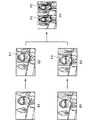
図2と図3を参照して、第1の顔枠合成処理について説明する。図2は、第1の顔枠合成処理を行う撮像装置100の機能ブロック図である。図3は、第1の顔枠合成処理を説明するための模式図である。
The first face frame synthesis process will be described with reference to FIGS. 2 and 3. FIG. 2 is a functional block diagram of the
図2に示すように、撮像装置100は、画像処理部212と、顔検出部214と、顔枠合成部216と、画像処理部222と、顔検出部224と、顔枠合成部226と、画像合成部232を有する。なお、画像処理部212、222と顔枠合成部216、226と画像合成部232は、図1に示すデジタル信号処理部108によって実行され、顔検出部214、224は、検出部130によって実行される。
As shown in FIG. 2, the
画像処理部212には、左画像の撮影用の撮像部から、立体画像を構成する左画像と右画像のうち左画像のデータが入力される。画像処理部212は、入力された左画像に対して各種の画像処理を行う。画像処理部212は、図3に示す画像処理後の左画像A1を、顔検出部214と顔枠合成部216に出力する。
The
顔検出部214は、画像処理部212から入力された左画像A1において人物の顔(顔に対応する領域)を検出する。左画像中に人物の顔が複数ある場合には、顔検出部214は、複数の顔を検出する。また、顔検出部214は、顔の位置も検出する。顔検出部214は、顔の検出結果を顔枠合成部216に出力する。
The
顔枠合成部216は、顔検出部214の検出結果に基づいて、画像処理部212から入力された左画像A1に顔枠F1を合成する。すなわち、顔枠合成部216は、人物の顔に対応した顔枠F1を左画像A1に合成して、図3に示す左画像A2を生成する。顔枠合成部216は、顔枠F1が合成された左画像A2を画像合成部232に出力する。
The face
画像処理部222には、右画像の撮影用の撮像部から、立体画像を構成する右画像のデータが入力される。画像処理部222は、入力された右画像に対して各種の画像処理を行う。画像処理部222は、図3に示す画像処理後の右画像B1を、顔検出部224と顔枠合成部226に出力する。なお、右画像B1と左画像A1は、異なる撮像部から撮像されたものであるため、視差がある。
The
顔検出部224は、画像処理部222から入力された右画像B1において人物の顔(顔に対応する領域)を検出する。右画像中に人物の顔が複数ある場合には、顔検出部224は、複数の顔を検出する。顔検出部224は、顔の検出結果を顔枠合成部226に出力する。
The
顔枠合成部226は、顔検出部224の検出結果に基づいて、画像処理部222から入力された右画像B1に顔枠F2を合成する。すなわち、顔枠合成部226は、人物の顔に対応した顔枠F2を右画像B1に合成して、図3に示す右画像B2を生成する。顔枠合成部216は、顔枠F2が合成された右画像B2を画像合成部232に出力する。
The face
画像合成部232は、顔枠合成部216から入力された左画像A2と、顔枠合成部226から入力された右画像B2とを、図3に示すように横に並べて1つのフレームC1に合成する(いわゆるサイド・バイ・サイド方式)。サイド・バイ・サイド方式において、フレームC1における左画像は、左画像A2の横幅を1/2に圧縮したものであり、フレームC1における右画像は、右画像B2の横幅を1/2に圧縮したものである。画像合成部232は、合成したフレームC1を表示部116(図1)に出力する。
The
表示部116は、入力されたフレームC1の左画像と右画像の横幅を2倍に伸ばして、順次表示する。左画像と右画像が順次表示される際に、ユーザは、例えばシャッターメガネを介して、右眼で右画像を視認し、左眼で左画像を視認する。なお、撮像装置100が、いわゆる偏光方式で画像を表示させて、ユーザに右画像と左画像を視認させても良い。そして、顔枠を含む右画像と左画像には視差あるため、ユーザは、図4に示すように、人物だけで無く、顔枠も奥行きがあるように知覚する。図4は、立体画像を説明するための模式図である。
The
第1の顔枠合成処理によれば、左画像と右画像に視差があるため、左画像に合成された顔枠F1と、右画像に合成された顔枠F2にも視差がある。そして、顔枠F1と顔枠F2の間の視差は、左画像と右画像の間の視差と同じであるため、ユーザが知覚する人物の顔の奥行きと顔枠の奥行きとが一致する。この結果、表示部116に画像を立体表示させる際に、ユーザは顔枠を違和感無く知覚できる。
According to the first face frame synthesis process, since the left image and the right image have parallax, the face frame F1 synthesized with the left image and the face frame F2 synthesized with the right image also have parallax. Since the parallax between the face frame F1 and the face frame F2 is the same as the parallax between the left image and the right image, the depth of the face of the person perceived by the user matches the depth of the face frame. As a result, when the image is stereoscopically displayed on the
(第2の顔枠合成処理)
次に、第2の顔枠合成処理について説明する。第2の顔枠合成処理は、まず、左画像と右画像の一方の画像(ここでは、左画像とする)に対して、顔検出及び奥行き検出を行う。次に、左画像の顔検出の結果に基づいて左画像に顔枠を合成し、左画像の顔枠と奥行き検出の結果に基づいて右画像に顔枠を合成する。
(Second face frame synthesis process)
Next, the second face frame synthesis process will be described. In the second face frame composition processing, first, face detection and depth detection are performed on one of the left image and the right image (here, the left image). Next, the face frame is combined with the left image based on the face detection result of the left image, and the face frame is combined with the right image based on the face frame of the left image and the depth detection result.
図5と図6を参照して、第2の顔枠合成処理について説明する。図5は、第2の顔枠合成処理を行う撮像装置100の機能ブロック図である。図6は、第2の顔枠合成処理を説明するための模式図である。
The second face frame synthesis process will be described with reference to FIGS. FIG. 5 is a functional block diagram of the
図5に示すように、撮像装置100は、画像処理部212と、顔検出部214と、奥行き検出部218と、画像処理部222と、画像合成部232を有する。なお、画像処理部212、222と画像合成部232は、図1のデジタル信号処理部108によって実行され、顔検出部214と奥行き検出部218は、検出部130によって実行される。
As illustrated in FIG. 5, the
画像処理部212には、立体画像を構成する左画像と右画像のうち左画像のデータが入力される。画像処理部212は、入力された左画像に対して各種の画像処理を行う。画像処理部212は、図6に示す画像処理後の左画像A1を、顔検出部214と奥行き検出部218と画像合成部232に出力する。
Data of the left image among the left image and the right image constituting the stereoscopic image is input to the
顔検出部214は、画像処理部212から入力された左画像A1において人物の顔(顔に対応する領域)を検出する。顔検出部214は、顔の検出結果を画像合成部232に出力する。
The
奥行き検出部218は、左画像A1における顔等の被写体の奥行きを検出する。例えば、奥行き検出部218は、画像における被写体の輝度コントラスト情報を取得することで、被写体の奥行きを検出する。奥行き検出部218は、奥行きの検出結果を画像合成部232に出力する。
The
画像処理部222には、立体画像を構成する右画像のデータが入力される。画像処理部222は、入力された右画像に対して各種の画像処理を行う。画像処理部222は、図5に示す画像処理後の右画像B1を、画像合成部232に出力する。
Data of the right image constituting the stereoscopic image is input to the
画像合成部232は、顔検出部214の検出結果に基づいて、左画像A1で検出された顔に対応した顔枠F1を生成し、生成した顔枠F1を左画像A1に合成する。また、画像合成部232は、左画像A1で検出された顔に対応した顔枠F1と、奥行き検出部218が検出した奥行きとに基いて、右画像B1に対応した顔枠F2を生成する。具体的には、画像合成部232は、検出された奥行きによって視差を取得し、顔枠F1に対して取得した視差分だけずらすことで顔枠F2を生成する。そして、画像合成部232は、生成した顔枠F2を右画像B1に合成する(図6参照)。
The
ところで、第2の顔枠合成処理においては奥行き検出部218により検出された奥行きにより視差が求まるので、第1の顔枠合成処理とは異なり、第2の顔枠合成処理では右画像の顔検出は行われない。
By the way, in the second face frame synthesis process, the parallax is obtained based on the depth detected by the
また、画像合成部232は、顔枠F1が合成された左画像と顔枠F2が合成された右画像とを、図6に示すように横に並べて1つのフレームC1に合成する(前述したサイド・バイ・サイド方式)。画像合成部232は、合成したフレームC1を表示部116に出力する。
Further, the
表示部116は、入力されたフレームC1の左画像と右画像の横幅を2倍に伸ばして、順次表示する。左画像と右画像が順次表示される際に、ユーザは、例えばシャッターメガネを介して、右眼で右画像を視認し、左眼で左画像を視認する。そして、顔枠を含む右画像と左画像には視差あるため、ユーザは、前述した図4に示すように、人物だけで無く、顔枠も奥行きがあるように知覚する。
The
第2の顔枠合成処理によれば、第1の顔枠合成処理と同様に、左画像に合成された顔枠F1と、右画像に合成された顔枠F2にも視差がある。そして、顔枠F1と顔枠F2の間の視差は、左画像と右画像の間の視差と同じであるため、ユーザが知覚する人物の顔の奥行きと顔枠の奥行きとが一致する。この結果、表示部116に画像を立体表示させる際に、ユーザは顔枠を違和感無く知覚できる。
According to the second face frame synthesis process, the face frame F1 synthesized with the left image and the face frame F2 synthesized with the right image also have parallax, as in the first face frame synthesis process. Since the parallax between the face frame F1 and the face frame F2 is the same as the parallax between the left image and the right image, the depth of the face of the person perceived by the user matches the depth of the face frame. As a result, when the image is stereoscopically displayed on the
また、第2の顔枠合成処理においては、上述したように右画像の顔検出が不要であるので、第1の顔枠合成処理に比べて処理量を低減でき、この結果処理時間を短縮することができる。 Further, in the second face frame synthesis process, as described above, the face detection of the right image is unnecessary, so that the processing amount can be reduced as compared with the first face frame synthesis process, and as a result, the processing time is shortened. be able to.
(第3の顔枠合成処理)
次に、第3の顔枠合成処理について説明する。第3の顔枠合成処理は、まず、左画像と右画像の一方の画像(ここでは、左画像とする)に対して顔検出を行う一方で、左画像と右画像の両方を用いて奥行き検出を行う。次に、左画像の顔検出に基いて左画像に顔枠を合成し、左画像の顔枠と、左画像及び右画像による奥行き検出との結果に基づいて、右画像に顔枠を合成する。
(Third face frame synthesis processing)
Next, the third face frame synthesis process will be described. In the third face frame synthesis process, first, face detection is performed on one of the left image and the right image (here, the left image), while the depth is determined using both the left image and the right image. Perform detection. Next, the face frame is synthesized with the left image based on the face detection of the left image, and the face frame is synthesized with the right image based on the result of the left image face frame and the depth detection by the left image and the right image. .
図7を参照して、第3の顔枠合成処理について説明する。図7は、第3の顔枠合成処理を行う撮像装置100の機能ブロック図である。
With reference to FIG. 7, the third face frame composition processing will be described. FIG. 7 is a functional block diagram of the
図7に示すように、撮像装置100は、画像処理部212と、顔検出部214と、奥行き検出部218と、画像処理部222と、画像合成部232を有する。なお、図7の画像処理部212、顔検出部214、及び画像処理部222は、それぞれ、図5の画像処理部212、顔検出部214、及び画像処理部222と同様な機能を有するので、説明は省く。
As illustrated in FIG. 7, the
奥行き検出部218は、左画像A1のみに基いて奥行きを検出する第2の顔枠合成処理とは異なり、左画像A1及び右画像B1に基いて顔等の被写体の奥行きを検出する。例えば、奥行き検出部218は、左画像A1と右画像B1の対応する特定の部分を抽出してブロックマッチングすることで、被写体の奥行きを検出する。奥行き検出部218は、奥行きの検出結果を画像合成部232に出力する。
The
画像合成部232は、顔検出部214の検出結果に基づいて、左画像A1で検出された顔に対応した顔枠F1を生成し、生成した顔枠F1を左画像A1に合成する。また、画像合成部232は、左画像A1で検出された顔に対応した顔枠F1と、奥行き検出部218が検出した奥行きとに基いて、右画像B1に対応した顔枠F2を生成する。そして、画像合成部232は、生成した顔枠F2を右画像B1に合成する(図6参照)。なお、生成された顔枠F2は、奥行き検出部218により奥行きが考慮されているため、顔枠F1に対して視差を有する。
The
また、画像合成部232は、顔枠F1が合成された左画像と顔枠F2が合成された右画像とを、図6に示すように横に並べて1つのフレームC1に合成し、合成したフレームC1を表示部116に出力する。表示部116は、前述した図4に示すように、顔枠F1が合成された左画像と顔枠F2が合成された右画像とを順次表示することで、人物だけで無く、顔枠も奥行きがあるように表示される。
Further, the
第3の顔枠合成処理によれば、第2の顔枠合成処理と同様に、左画像に合成された顔枠F1と、右画像に合成された顔枠F2にも視差がある。そして、顔枠F1と顔枠F2の間の視差は、左画像と右画像の間の視差と同じであるため、ユーザが知覚する人物の顔の奥行きと顔枠の奥行きとが一致する。この結果、表示部116に画像を立体表示させる際に、ユーザは顔枠を違和感無く知覚できる。
According to the third face frame synthesis process, the face frame F1 synthesized with the left image and the face frame F2 synthesized with the right image also have parallax, as in the second face frame synthesis process. Since the parallax between the face frame F1 and the face frame F2 is the same as the parallax between the left image and the right image, the depth of the face of the person perceived by the user matches the depth of the face frame. As a result, when the image is stereoscopically displayed on the
また、第3の顔枠合成処理によれば、左画像及び右画像に基いて奥行きを検出するので、左画像と右画像の一方の画像のみに基いて奥行きを検出する場合に比べて、より高精度に奥行きを検出可能である。 Further, according to the third face frame synthesis process, the depth is detected based on the left image and the right image, and therefore, compared to the case where the depth is detected based on only one of the left image and the right image. Depth can be detected with high accuracy.
なお、上記では3つの顔枠合成処理を説明したが、撮像装置100が実行可能な顔枠合成処理は、これに限定されない。以下において、前述した図5を参照しながら、他の顔枠合成処理について説明する。
In the above description, three face frame synthesis processes have been described. However, the face frame synthesis process that can be executed by the
他の顔枠合成処理では、奥行き検出部218は、連続した2つの左画像を用いて奥行きを検出する。連続した2つの画像の間には、時間差があるため画像の変化がある。そこで、奥行き検出部218は、時間差がある2つの左画像から奥行きを検出する。例えば、奥行き検出部218は、2つの左画像の対応する特定の部分を抽出してブロックマッチングすることで、奥行きを検出する。そして、画像合成部232は、検出された奥行きと左画像の顔検出の結果に基づいて、右画像の顔枠を生成する。このように生成された右画像の顔枠も、前述した3つの顔枠合成処理と同様に、左画像の顔枠と視差が異なる。
In other face frame synthesis processing, the
<3.顔枠合成処理の選択処理>
上記では、撮像装置100が実行可能な複数の顔枠合成処理を説明したが、撮像装置100の制御部110は、被写体の撮影状態に応じて、複数の顔枠合成処理のうちの1つの顔枠合成処理を選択して実行する。これにより、リアルタイムで立体表示を行う際に、複数の顔枠合成処理の中から、奥行き検出等の検出精度や顔枠合成処理の処理時間を考慮した、最適な顔枠合成処理を実行できる。
<3. Selection processing for face frame synthesis processing>
In the above description, a plurality of face frame compositing processes that can be executed by the
例えば、制御部110は、同一の平面内において、検出された顔の位置がフォーカス位置(例えば、ファインダ内の中心位置)と一致するか否かに応じて、複数の顔枠合成処理のうちの1つの顔枠合成処理を選択して実行する。具体的には、制御部110は、同一の平面内において、検出された顔の位置がフォーカス位置と一致する場合には、第2の顔枠合成処理を選択して実行する。一方で、同一の平面内において、検出された顔の位置がフォーカス位置と一致しない場合には、制御部110は、第1の顔枠合成処理又は第3の顔枠合成処理を選択して実行する。
For example, the
同一の平面内において、検出された顔の位置がフォーカス位置と一致した場合の奥行き検出の精度は、顔の位置がフォーカス位置と一致しない場合の奥行き検出の精度よりも高精度である。このため、顔の位置がフォーカス位置と一致する場合には、左画像と右画像のうちの一方の画像から奥行きを検出しても(第2の顔枠合成処理)、奥行き検出の精度が良く、処理時間も短くできる。一方で、顔の位置がフォーカス位置と一致しない場合には、左画像と右画像の両方を用いて奥行きを検出することで(第1の顔枠合成処理又は第3の顔枠合成処理)、奥行き検出の精度の低下を防止できる。 In the same plane, the depth detection accuracy when the detected face position matches the focus position is higher than the depth detection accuracy when the face position does not match the focus position. Therefore, when the face position matches the focus position, the depth detection accuracy is good even if the depth is detected from one of the left image and the right image (second face frame synthesis process). The processing time can be shortened. On the other hand, when the face position does not match the focus position, by detecting the depth using both the left image and the right image (first face frame synthesis process or third face frame synthesis process), Degradation of depth detection accuracy can be prevented.
また、例えば、制御部110は、顔検出部214(顔検出部224)によって検出された顔の数に応じて、3つの顔枠合成処理のうちの1つの顔枠合成処理を選択して実行する。具体的には、制御部110は、検出された顔の数が所定数よりも多い場合には、第3の顔枠合成処理を選択して実行し、検出された顔の数が所定数よりも少ない場合には、第1の顔枠合成処理を選択して実行する。ここで、所定数は、以下のように定まる。奥行き検出部218による奥行き検出時間は、一定時間であるのに対して、顔検出部214による顔検出時間は、顔の数に比例して長くなる。所定数は、所定数の数の顔を検出する顔検出時間が奥行き検出時間よりも長くなる最小の数である。
Further, for example, the
顔の数に応じて、3つの顔枠合成処理のうちの1つの顔枠合成処理を選択して実行する場合には、以下のようなメリットがある。画像中の顔の数が多い程、制御部110の処理量が増える。第3の顔枠合成処理は、右画像の顔検出が不要であるので、検出された顔の数が多い程、右画像の顔検出を行う第1の顔枠合成処理に比べて処理量が少ない。このため、顔の数が多い場合には第3の顔枠合成処理を選択して実行することで、顔枠合成処理の処理量の増加を防止できる。一方で、顔の数が少ない場合には、第1の顔枠合成処理を実行することで、顔枠F1と顔枠F2の視差を精度良いものにできる。
There are the following merits when selecting and executing one of the three face frame composition processes according to the number of faces. As the number of faces in the image increases, the processing amount of the
(顔枠合成処理の選択処理の具体例)
図8を参照して、顔枠合成処理の選択処理の具体例について説明する。図8は、顔枠合成処理の選択処理を説明するためのフローチャートである。本処理は、制御部110がROM120等に記憶されたプログラムを実行することで、実現される。
(Specific example of selection processing for face frame synthesis processing)
A specific example of the selection process of the face frame synthesis process will be described with reference to FIG. FIG. 8 is a flowchart for explaining the selection process of the face frame synthesis process. This process is realized by the
図8のフローチャートは、顔検出部214が、入力された左画像の顔を検出したところから開始される。なお、以下の処理においては、第1の顔枠合成処理と第2の顔枠合成処理と第3の顔枠合成処理の中から、1つの顔枠合成処理を選択するものとする。
The flowchart in FIG. 8 starts when the
制御部110は、まず、顔検出部214によって検出された顔検出の精度が、良いか否かを判定する(ステップS102)。例えば、制御部110は、顔検出の精度の度合いを示す数値(閾値)等を予め把握しており、検出された精度が閾値よりも大きい場合には、精度が良いと判断し、検出された精度が閾値よりも小さい場合には、精度が悪いと判断する。
First, the
ステップS102で顔検出の精度が良いと判定された場合には(Yes)、制御部110は、検出された顔の数が1つで、かつ、検出された顔の位置とフォーカス位置が一致するか否かを判定する(ステップS104)。
When it is determined in step S102 that the face detection accuracy is good (Yes), the
ステップS104でYesと判定された場合には、制御部110は、図5に示す第2の顔枠合成処理を実行する(ステップS106)。これにより、奥行き検出の精度を高め、また、処理時間も短くできる。ステップS104でNoと判定された場合には、制御部110は、検出された顔の数が所定数よりも多いか否かを判定する(ステップS108)。
When it is determined Yes in step S104, the
ステップS108で顔の数が所定数よりも多い場合には(Yes)、制御部110は、図7に示す第3の顔枠合成処理を選択して実行する(ステップS110)。このように、顔の数が多い場合には第3の顔枠合成処理を選択して実行することで、他の顔枠合成処理に比べて、顔枠合成処理の処理量の増加を防止できる。ステップS108で顔の数が所定数よりも少ない場合には(No)、制御部110は、図2に示す第1の顔枠合成処理を選択して実行する(ステップS112)。第1の顔枠合成処理を実行することで、顔枠F1と顔枠F2の視差を精度良いものにできる。
When the number of faces is larger than the predetermined number in step S108 (Yes), the
ステップS102で顔検出の精度が悪いと判定された場合には(No)、制御部110は、検出された顔の数が1つで、かつ、検出された顔の位置とフォーカス位置が一致するか否かを判定する(ステップS114)。
If it is determined in step S102 that the face detection accuracy is poor (No), the
ステップS114でYesと判定された場合には、制御部110は、第2の顔枠合成処理を実行する(ステップS116)。これにより、奥行き検出の精度を高め、また、処理時間も短くできる。ステップS114でNoと判定された場合には、制御部110は、第3の顔枠合成処理を実行する(ステップS118)。これにより、奥行き検出の精度の低下を防止できる。
When it determines with Yes by step S114, the
上述した本処理によれば、リアルタイムで立体表示を行う際に、複数の顔枠合成処理の中から、奥行き検出等の検出精度や顔枠合成処理の処理時間を考慮した、最適な顔枠合成処理を実行できる。 According to the above-described process, when performing stereoscopic display in real time, an optimal face frame synthesis that takes into account detection accuracy such as depth detection and the processing time of the face frame synthesis process among a plurality of face frame synthesis processes. Processing can be executed.
<4.まとめ>
上述したように、本実施形態に係る撮像装置100は、視差が異なる第1入力画像(例えば、左画像)及び第2入力画像(例えば、右画像)の少なくともいずれか一方の入力画像中の所定の被写体(例えば、顔)を検出する。次に、撮像装置100は、検出された顔に対応した顔枠を、表示部116に立体表示される左画像と右画像の間で奥行きがあるように、左画像及び右画像にそれぞれ合成する。
<4. Summary>
As described above, the
このような顔枠合成処理によれば、立体画像を構成する二つの画像のそれぞれに、二つの画像の視差に対応した2つの顔枠を合成させるので、ユーザが知覚する被写体の奥行きと被写体枠の奥行きとが一致する。この結果、表示部116に画像を立体表示させる際に、ユーザは被写体枠を違和感無く知覚できる。
According to such face frame synthesis processing, two face frames corresponding to the parallax of the two images are synthesized with each of the two images constituting the stereoscopic image, so that the depth of the subject perceived by the user and the subject frame The depth matches. As a result, when the image is stereoscopically displayed on the
以上、添付図面を参照しながら本開示の好適な実施形態について詳細に説明したが、本技術はかかる例に限定されない。本開示の技術分野における通常の知識を有する者であれば、特許請求の範囲に記載された技術的思想の範疇内において、各種の変更例または修正例に想到し得ることは明らかであり、これらについても、当然に本開示の技術的範囲に属するものと了解される。 The preferred embodiments of the present disclosure have been described in detail above with reference to the accompanying drawings, but the present technology is not limited to such examples. It is obvious that a person having ordinary knowledge in the technical field of the present disclosure can come up with various changes or modifications within the scope of the technical idea described in the claims. Of course, it is understood that it belongs to the technical scope of the present disclosure.
上記では、被写体として人物の顔を例に挙げて説明したが、これに限定されない。例えば、被写体は、人物全体、ペット、植物等の特定の物体であっても良い。 In the above description, a human face is taken as an example of the subject, but the present invention is not limited to this. For example, the subject may be a specific object such as an entire person, a pet, or a plant.
また、上記では、画像処理装置として、ビデオカメラ等の撮像装置を例に挙げて説明したが、これに限定されない。例えば、画像処理装置は、画像データを表示部に立体表示させる機能を有すれば良く、例えば、携帯電話機、PDA、ゲーム機、電子辞書、ノートパソコン等であっても良い。また、画像処理装置は、外部の表示装置に画像を表示させても良い。 In the above description, an imaging apparatus such as a video camera has been described as an example of the image processing apparatus. However, the present invention is not limited to this. For example, the image processing apparatus only needs to have a function of stereoscopically displaying image data on the display unit. For example, the image processing apparatus may be a mobile phone, a PDA, a game machine, an electronic dictionary, a laptop computer, or the like. The image processing apparatus may display an image on an external display device.
また、上記の実施形態のフローチャートに示されたステップは、記載された順序に沿って時系列的に行われる処理はもちろん、必ずしも時系列的に処理されなくとも、並列的に又は個別的に実行される処理をも含む。また時系列的に処理されるステップでも、場合によっては適宜順序を変更することが可能であることは言うまでもない。 In addition, the steps shown in the flowcharts of the above-described embodiments are executed in parallel or individually even if they are not necessarily processed in time series, as well as processes performed in time series in the order described. Including processing to be performed. Further, it goes without saying that the order can be appropriately changed even in the steps processed in time series.
なお、本技術は以下のような構成も取ることができる。
(1)視差が異なる第1入力画像及び第2入力画像の少なくともいずれか一方の入力画像中の所定の被写体を検出する被写体検出部と、
検出された前記被写体に対応した被写体枠を、表示部に立体表示される前記第1入力画像と前記第2入力画像の間で奥行きがあるように、前記第1入力画像及び前記第2入力画像にそれぞれ合成する合成部と、
を備える、画像処理装置。
(2)前記被写体検出部は、前記被写体の顔を検出し、
前記被写体枠は、前記顔に対応した顔枠である、前記(1)に記載の画像処理装置。
(3)前記合成部は、
前記第1入力画像で検出された前記被写体に対応した第1被写体枠を、前記第1入力画像に合成すると共に、
前記第2入力画像で検出された前記被写体に対応した第2被写体枠を、前記第2入力画像に合成する、前記(1)又は(2)に記載の画像処理装置。
(4)前記第1入力画像に基いて、前記被写体の奥行きを検出する奥行き検出部を更に備え、
前記合成部は、
前記第1入力画像で検出された前記被写体に対応した第1被写体枠を、前記第1入力画像に合成すると共に、
前記第1被写体枠と前記奥行き検出部が検出した前記奥行きとに基いて生成した第2被写体枠を、前記第2入力画像に合成する、前記(1)又は(2)に記載の画像処理装置。
(5)前記第1入力画像及び前記第2入力画像に基いて、前記被写体の奥行きを検出する奥行き検出部を更に備え、
前記合成部は、
前記第1入力画像で検出された前記被写体に対応した第1被写体枠を、前記第1入力画像に合成すると共に、
前記第1被写体枠と前記奥行き検出部が検出した前記奥行きとに基いて生成した第2被写体枠を、前記第2入力画像に合成する、前記(1)又は(2)に記載の画像処理装置。
(6)前記第1入力画像に基いて、前記被写体の奥行きを検出する奥行き検出部と、
前記合成部が、前記第1入力画像で検出された前記被写体に対応した第1被写体枠を、前記第1入力画像に合成すると共に、前記第2入力画像で検出された前記被写体に対応した第2被写体枠を、前記第2入力画像に合成する第1処理と、
前記合成部が、前記第1入力画像で検出された前記被写体に対応した第1被写体枠を、前記第1入力画像に合成すると共に、前記第1被写体枠と前記奥行き検出部が検出した前記奥行きとに基いて生成した第2被写体枠を、前記第2入力画像に合成する第2処理と、
のいずれか一方を選択して実行する制御部と、
を更に備える、前記(1)〜(4)のいずれかに記載の画像処理装置。
(7)前記制御部は、
前記被写体検出部によって検出された前記被写体の数が所定数よりも多い場合には、前記第2処理を選択して実行し、
前記被写体検出部によって検出された前記被写体の数が所定数よりも少ない場合には、前記第1処理を選択して実行する、前記(6)に記載の画像処理装置。
(8)前記制御部は、
入力画像におけるフォーカス位置と、検出された前記顔の位置とを検出し、
前記フォーカス位置が前記被写体の位置と一致する場合には、前記第2処理を選択して実行し、
前記フォーカス位置が前記被写体の位置と一致しない場合には、前記第1処理を選択して実行する、前記(6)に記載の画像処理装置。
(9)視差が異なる第1入力画像及び第2入力画像の少なくともいずれか一方の入力画像中の所定の被写体を検出することと、
検出された前記被写体に対応した被写体枠を、表示部に立体表示される前記第1入力画像と前記第2入力画像の間で奥行きがあるように、前記第1入力画像及び前記第2入力画像にそれぞれ合成することと、
を有する、画像処理方法。
(10)視差が異なる第1入力画像及び第2入力画像の少なくともいずれか一方の入力画像中の所定の被写体を検出することと、
検出された前記被写体に対応した被写体枠を、表示部に立体表示される前記第1入力画像と前記第2入力画像の間で奥行きがあるように、前記第1入力画像及び前記第2入力画像にそれぞれ合成することと、
をコンピュータに実行させるための、プログラム。
In addition, this technique can also take the following structures.
(1) a subject detection unit that detects a predetermined subject in at least one of the first input image and the second input image having different parallaxes;
The first input image and the second input image so that a subject frame corresponding to the detected subject has a depth between the first input image and the second input image that are stereoscopically displayed on the display unit. And a synthesis unit to synthesize each of
An image processing apparatus comprising:
(2) The subject detection unit detects the face of the subject,
The image processing apparatus according to (1), wherein the subject frame is a face frame corresponding to the face.
(3) The synthesis unit
A first subject frame corresponding to the subject detected in the first input image is combined with the first input image;
The image processing apparatus according to (1) or (2), wherein a second subject frame corresponding to the subject detected in the second input image is combined with the second input image.
(4) a depth detection unit that detects the depth of the subject based on the first input image;
The synthesis unit is
A first subject frame corresponding to the subject detected in the first input image is combined with the first input image;
The image processing apparatus according to (1) or (2), wherein a second subject frame generated based on the first subject frame and the depth detected by the depth detection unit is combined with the second input image. .
(5) a depth detection unit that detects the depth of the subject based on the first input image and the second input image;
The synthesis unit is
A first subject frame corresponding to the subject detected in the first input image is combined with the first input image;
The image processing apparatus according to (1) or (2), wherein a second subject frame generated based on the first subject frame and the depth detected by the depth detection unit is combined with the second input image. .
(6) a depth detector that detects the depth of the subject based on the first input image;
The synthesizing unit synthesizes a first subject frame corresponding to the subject detected in the first input image with the first input image and a first subject frame corresponding to the subject detected in the second input image. A first process for combining two subject frames with the second input image;
The combining unit combines the first subject frame corresponding to the subject detected in the first input image with the first input image, and the depth detected by the first subject frame and the depth detection unit. A second process for combining the second subject frame generated based on the second input image with the second input image;
A control unit that selects and executes either one of
The image processing apparatus according to any one of (1) to (4), further including:
(7) The control unit
If the number of subjects detected by the subject detection unit is greater than a predetermined number, the second process is selected and executed,
The image processing apparatus according to (6), wherein the first process is selected and executed when the number of the objects detected by the object detection unit is smaller than a predetermined number.
(8) The control unit
Detecting the focus position in the input image and the position of the detected face,
When the focus position matches the position of the subject, the second process is selected and executed,
The image processing apparatus according to (6), wherein when the focus position does not coincide with the position of the subject, the first process is selected and executed.
(9) detecting a predetermined subject in at least one of the first input image and the second input image having different parallaxes;
The first input image and the second input image so that a subject frame corresponding to the detected subject has a depth between the first input image and the second input image that are stereoscopically displayed on the display unit. Respectively, and
An image processing method.
(10) detecting a predetermined subject in at least one of the first input image and the second input image having different parallaxes;
The first input image and the second input image so that a subject frame corresponding to the detected subject has a depth between the first input image and the second input image that are stereoscopically displayed on the display unit. Respectively, and
A program that causes a computer to execute.
100 撮像装置
101 フォーカスレンズ
102 ズームレンズ
103 撮像素子
104 アナログ信号処理部
105 A/D変換部
106 タイミングジェネレータ(TA)
107 垂直ドライバ
108 デジタル信号処理部
110 制御部
112 モータドライバ
113 フォーカスレンズ駆動モータ
114 ズームレンズ駆動モータ
115 記録デバイス
116 表示部
118 操作部
119 メモリ(EEPROM)
120 メモリ(ROM)
121 メモリ(RAM)
212 画像処理部
214 顔検出部
216 顔枠合成部
218 奥行き検出部
222 画像処理部
224 顔検出部
226 顔枠合成部
232 画像合成部
F1、F2 顔枠
DESCRIPTION OF
120 memory (ROM)
121 Memory (RAM)
212
Claims (7)
前記第1入力画像に基づいて、前記被写体の奥行きを検出する奥行き検出部と、
前記被写体に対応した第1被写体枠を、前記第1入力画像に合成すると共に、前記第1被写体枠と前記奥行きとに基づいて生成した第2被写体枠を、前記第1入力画像と視差が異なり前記奥行きの検出には用いない第2入力画像に合成する合成部と、
を備える、画像処理装置。 A subject detection unit for detecting a predetermined subject based on the first input image;
A depth detector for detecting the depth of the subject based on the first input image;
The first subject frame corresponding to the subject is combined with the first input image, and the second subject frame generated based on the first subject frame and the depth is different in parallax from the first input image. a combining unit for synthesis to a second input image is not used for detection of the depth,
An image processing apparatus comprising:
前記第1被写体枠および前記第2被写体枠は、前記顔に対応した顔枠である、請求項1に記載の画像処理装置。 The subject detection unit detects a face of the subject,
The image processing apparatus according to claim 1, wherein the first subject frame and the second subject frame are face frames corresponding to the face.
前記第1入力画像から検出した前記被写体に対応した第1被写体枠を、前記第1入力画像に合成すると共に、前記第2入力画像から検出した前記被写体に対応した第2被写体枠を、前記第2入力画像に合成する第1処理と、
前記合成部が、
前記第1入力画像から検出した前記被写体に対応した第1被写体枠を、前記第1入力画像に合成すると共に、前記第1被写体枠と前記奥行きとに基づいて生成した第2被写体枠を、前記第2入力画像に合成する第2処理と、
のいずれか一方を選択して実行する制御部、
を更に備える、請求項1または2に記載の画像処理装置。 Before Symbol synthesis section,
The first object frame corresponding to the subject detected from the first input image, the synthesized on the first input image, the second object frame corresponding to the subject detected from the second input image, the first A first process for compositing to a two-input image;
The combining unit is
Wherein the first object frame corresponding to the subject detected from the first input image, the synthesized on the first input image, the second object frame generated based on said the first object frame depth, the A second process to be combined with the second input image;
Control unit for selecting and executing either one of,
Further comprising, an image processing apparatus according to claim 1 or 2.
前記第1入力画像におけるフォーカス位置と、前記第1入力画像から検出した前記被写体の位置とを検出し、
前記フォーカス位置が前記被写体の位置と一致する場合には、前記第2処理を選択して実行し、
前記フォーカス位置が前記被写体の位置と一致しない場合には、前記第1処理を選択して実行する、請求項3に記載の画像処理装置。 The controller is
A focus position in the first input image, detects the position of the subject detected from the first input image,
When the focus position matches the position of the subject, the second process is selected and executed,
The image processing apparatus according to claim 3 , wherein the first process is selected and executed when the focus position does not coincide with the position of the subject.
前記第1入力画像に基づいて、前記被写体の奥行きを検出することと、
前記被写体に対応した第1被写体枠を、前記第1入力画像に合成すると共に、前記第1被写体枠と前記奥行きとに基づいて生成した第2被写体枠を、前記第1入力画像と視差が異なり前記奥行きの検出には用いない第2入力画像に合成することと、
を有する、画像処理方法。 Detecting a predetermined subject based on the first input image;
Detecting the depth of the subject based on the first input image;
The first subject frame corresponding to the subject is combined with the first input image, and the second subject frame generated based on the first subject frame and the depth is different in parallax from the first input image. the method comprising synthesis into the second input image is not used for detection of the depth,
An image processing method.
前記第1入力画像に基づいて、前記被写体の奥行きを検出することと、
前記被写体に対応した第1被写体枠を、前記第1入力画像に合成すると共に、前記第1被写体枠と前記奥行きとに基づいて生成した第2被写体枠を、前記第1入力画像と視差が異なり前記奥行きの検出には用いない第2入力画像に合成することと、
をコンピュータに実行させるための、プログラム。 Detecting a predetermined subject based on the first input image;
Detecting the depth of the subject based on the first input image;
The first subject frame corresponding to the subject is combined with the first input image, and the second subject frame generated based on the first subject frame and the depth is different in parallax from the first input image. the method comprising synthesis into the second input image is not used for detection of the depth,
A program that causes a computer to execute.
を備える、画像処理装置。 Based on the depth of the subject detected from the first input image , information corresponding to a specific subject in the first input image and the second input image having different parallaxes , the first input image and the second input image A synthesizing unit that synthesizes each of the specific subjects.
An image processing apparatus comprising:
Priority Applications (9)
| Application Number | Priority Date | Filing Date | Title |
|---|---|---|---|
| JP2011087211A JP5874192B2 (en) | 2011-04-11 | 2011-04-11 | Image processing apparatus, image processing method, and program |
| US13/430,840 US9179121B2 (en) | 2011-04-11 | 2012-03-27 | Imaging processing apparatus, image processing method, and program |
| EP17181162.3A EP3255887B1 (en) | 2011-04-11 | 2012-03-27 | Imaging processing apparatus, image processing method, and program |
| EP12161409.3A EP2512144B1 (en) | 2011-04-11 | 2012-03-27 | Imaging processing apparatus, image processing method, and program |
| TW101111508A TW201246914A (en) | 2011-04-11 | 2012-03-30 | Imaging processing apparatus, image processing method, and program |
| CN201210096079.3A CN102739958B (en) | 2011-04-11 | 2012-04-01 | Imaging processing apparatus and image processing method |
| KR1020120034576A KR20120115944A (en) | 2011-04-11 | 2012-04-03 | Image processing apparatus, image processing method, and program |
| US14/869,412 US9591291B2 (en) | 2011-04-11 | 2015-09-29 | Imaging processing apparatus, image processing method, and program |
| US15/417,893 US9948921B2 (en) | 2011-04-11 | 2017-01-27 | Imaging processing apparatus, image processing method, and program |
Applications Claiming Priority (1)
| Application Number | Priority Date | Filing Date | Title |
|---|---|---|---|
| JP2011087211A JP5874192B2 (en) | 2011-04-11 | 2011-04-11 | Image processing apparatus, image processing method, and program |
Publications (3)
| Publication Number | Publication Date |
|---|---|
| JP2012222641A JP2012222641A (en) | 2012-11-12 |
| JP2012222641A5 JP2012222641A5 (en) | 2014-05-22 |
| JP5874192B2 true JP5874192B2 (en) | 2016-03-02 |
Family
ID=46062028
Family Applications (1)
| Application Number | Title | Priority Date | Filing Date |
|---|---|---|---|
| JP2011087211A Expired - Fee Related JP5874192B2 (en) | 2011-04-11 | 2011-04-11 | Image processing apparatus, image processing method, and program |
Country Status (6)
| Country | Link |
|---|---|
| US (3) | US9179121B2 (en) |
| EP (2) | EP3255887B1 (en) |
| JP (1) | JP5874192B2 (en) |
| KR (1) | KR20120115944A (en) |
| CN (1) | CN102739958B (en) |
| TW (1) | TW201246914A (en) |
Families Citing this family (8)
| Publication number | Priority date | Publication date | Assignee | Title |
|---|---|---|---|---|
| JP5874192B2 (en) * | 2011-04-11 | 2016-03-02 | ソニー株式会社 | Image processing apparatus, image processing method, and program |
| JP6516410B2 (en) * | 2014-02-21 | 2019-05-22 | キヤノン株式会社 | Image processing apparatus, image processing method and program |
| CN103945133B (en) * | 2014-05-08 | 2017-04-26 | 山东神戎电子股份有限公司 | Auto-focus device and method for visible light lens |
| CN105376484A (en) * | 2015-11-04 | 2016-03-02 | 深圳市金立通信设备有限公司 | Image processing method and terminal |
| CN107358638B (en) * | 2017-07-19 | 2020-11-27 | 智车优行科技(北京)有限公司 | Disparity map calculation method and device, electronic equipment and computer storage medium |
| CN110225235B (en) * | 2018-03-01 | 2021-03-09 | 浙江宇视科技有限公司 | Zoom following method and electric lens |
| KR102316960B1 (en) * | 2019-11-28 | 2021-10-22 | 광운대학교 산학협력단 | Method and apparatus for realtime object detection in unmanned aerial vehicle image |
| KR102393702B1 (en) * | 2021-10-18 | 2022-05-04 | 주식회사 스튜디오레논 | Method for generating a facial image of a virtual character through deep learning-based optimized operation, and computer readable recording medium and system therefor |
Family Cites Families (14)
| Publication number | Priority date | Publication date | Assignee | Title |
|---|---|---|---|---|
| US7643025B2 (en) * | 2003-09-30 | 2010-01-05 | Eric Belk Lange | Method and apparatus for applying stereoscopic imagery to three-dimensionally defined substrates |
| US7356408B2 (en) | 2003-10-17 | 2008-04-08 | Fuji Jukogyo Kabushiki Kaisha | Information display apparatus and information display method |
| JP2009047498A (en) * | 2007-08-17 | 2009-03-05 | Fujifilm Corp | Stereoscopic imaging device, control method of stereoscopic imaging device, and program |
| JP5115139B2 (en) * | 2007-10-17 | 2013-01-09 | ソニー株式会社 | Composition determination apparatus, composition determination method, and program |
| JP2009290255A (en) | 2008-05-27 | 2009-12-10 | Sony Corp | Imaging apparatus, imaging apparatus control method and computer program |
| JP4991685B2 (en) | 2008-12-19 | 2012-08-01 | 富士フイルム株式会社 | Stereoscopic image processing apparatus and stereoscopic image processing method |
| JP5620651B2 (en) * | 2009-06-26 | 2014-11-05 | キヤノン株式会社 | REPRODUCTION DEVICE, IMAGING DEVICE, AND CONTROL METHOD THEREOF |
| JP5450200B2 (en) * | 2009-07-17 | 2014-03-26 | 富士フイルム株式会社 | Imaging apparatus, method and program |
| US20110025830A1 (en) * | 2009-07-31 | 2011-02-03 | 3Dmedia Corporation | Methods, systems, and computer-readable storage media for generating stereoscopic content via depth map creation |
| JP5346266B2 (en) * | 2009-09-30 | 2013-11-20 | 富士フイルム株式会社 | Image processing apparatus, camera, and image processing method |
| JP2011087211A (en) | 2009-10-19 | 2011-04-28 | Sony Corp | Demodulation device and method, and electronic apparatus |
| US8913056B2 (en) * | 2010-08-04 | 2014-12-16 | Apple Inc. | Three dimensional user interface effects on a display by using properties of motion |
| JP2012114896A (en) * | 2010-11-04 | 2012-06-14 | Panasonic Corp | Three-dimensional imaging apparatus and three-dimensional reproduction apparatus |
| JP5874192B2 (en) * | 2011-04-11 | 2016-03-02 | ソニー株式会社 | Image processing apparatus, image processing method, and program |
-
2011
- 2011-04-11 JP JP2011087211A patent/JP5874192B2/en not_active Expired - Fee Related
-
2012
- 2012-03-27 EP EP17181162.3A patent/EP3255887B1/en active Active
- 2012-03-27 EP EP12161409.3A patent/EP2512144B1/en not_active Not-in-force
- 2012-03-27 US US13/430,840 patent/US9179121B2/en not_active Expired - Fee Related
- 2012-03-30 TW TW101111508A patent/TW201246914A/en unknown
- 2012-04-01 CN CN201210096079.3A patent/CN102739958B/en not_active Expired - Fee Related
- 2012-04-03 KR KR1020120034576A patent/KR20120115944A/en not_active Application Discontinuation
-
2015
- 2015-09-29 US US14/869,412 patent/US9591291B2/en active Active
-
2017
- 2017-01-27 US US15/417,893 patent/US9948921B2/en active Active
Also Published As
| Publication number | Publication date |
|---|---|
| CN102739958A (en) | 2012-10-17 |
| US20170142409A1 (en) | 2017-05-18 |
| EP3255887A1 (en) | 2017-12-13 |
| JP2012222641A (en) | 2012-11-12 |
| CN102739958B (en) | 2017-05-17 |
| US9948921B2 (en) | 2018-04-17 |
| TW201246914A (en) | 2012-11-16 |
| US20160021359A1 (en) | 2016-01-21 |
| US20120256910A1 (en) | 2012-10-11 |
| US9179121B2 (en) | 2015-11-03 |
| US9591291B2 (en) | 2017-03-07 |
| EP2512144A1 (en) | 2012-10-17 |
| EP3255887B1 (en) | 2022-02-09 |
| EP2512144B1 (en) | 2017-08-30 |
| KR20120115944A (en) | 2012-10-19 |
Similar Documents
| Publication | Publication Date | Title |
|---|---|---|
| JP5874192B2 (en) | Image processing apparatus, image processing method, and program | |
| US9007442B2 (en) | Stereo image display system, stereo imaging apparatus and stereo display apparatus | |
| US20140028806A1 (en) | Imaging device and imaging method | |
| US20120263372A1 (en) | Method And Apparatus For Processing 3D Image | |
| JP5371845B2 (en) | Imaging apparatus, display control method thereof, and three-dimensional information acquisition apparatus | |
| EP2833638B1 (en) | Image processing device, imaging device, and image processing method | |
| JP5647740B2 (en) | Parallax adjusting apparatus and method, photographing apparatus, reproduction display apparatus | |
| JP5295426B2 (en) | Compound eye imaging apparatus, parallax adjustment method and program thereof | |
| JP2013042301A (en) | Image processor, image processing method, and program | |
| WO2012002157A1 (en) | Image capture device for stereoscopic viewing-use and control method of same | |
| JP2017041887A (en) | Image processing system, imaging apparatus, image processing method and program | |
| JP6155471B2 (en) | Image generating apparatus, imaging apparatus, and image generating method | |
| US20120314038A1 (en) | Stereoscopic image obtaining apparatus | |
| JPWO2014064946A1 (en) | Imaging apparatus, image processing apparatus, control program for imaging apparatus, and control program for image processing apparatus | |
| WO2012043003A1 (en) | Three-dimensional image display device, and three-dimensional image display method | |
| JP5580486B2 (en) | Image output apparatus, method and program | |
| US20130076867A1 (en) | Imaging apparatus | |
| JP2016036081A (en) | Image processing device, method and program, and recording medium | |
| JPWO2012001958A1 (en) | Image processing apparatus and method, and program | |
| JP2012028871A (en) | Stereoscopic image display device, stereoscopic image photographing device, stereoscopic image display method, and stereoscopic image display program | |
| WO2013136832A1 (en) | Stereoscopic image display control device and stereoscopic image display control method | |
| JP2015139019A (en) | Device and program for image composition | |
| WO2012105122A1 (en) | Stereoscopic imaging device and motion control method therefor | |
| WO2013001839A1 (en) | Image pick-up device | |
| JP2015046820A (en) | Imaging device and imaging system |
Legal Events
| Date | Code | Title | Description |
|---|---|---|---|
| A521 | Request for written amendment filed |
Free format text: JAPANESE INTERMEDIATE CODE: A523 Effective date: 20140407 |
|
| A621 | Written request for application examination |
Free format text: JAPANESE INTERMEDIATE CODE: A621 Effective date: 20140407 |
|
| A977 | Report on retrieval |
Free format text: JAPANESE INTERMEDIATE CODE: A971007 Effective date: 20141211 |
|
| A131 | Notification of reasons for refusal |
Free format text: JAPANESE INTERMEDIATE CODE: A131 Effective date: 20141216 |
|
| A521 | Request for written amendment filed |
Free format text: JAPANESE INTERMEDIATE CODE: A523 Effective date: 20150210 |
|
| A02 | Decision of refusal |
Free format text: JAPANESE INTERMEDIATE CODE: A02 Effective date: 20150818 |
|
| A521 | Request for written amendment filed |
Free format text: JAPANESE INTERMEDIATE CODE: A523 Effective date: 20151111 |
|
| A911 | Transfer to examiner for re-examination before appeal (zenchi) |
Free format text: JAPANESE INTERMEDIATE CODE: A911 Effective date: 20151119 |
|
| TRDD | Decision of grant or rejection written | ||
| A01 | Written decision to grant a patent or to grant a registration (utility model) |
Free format text: JAPANESE INTERMEDIATE CODE: A01 Effective date: 20151222 |
|
| A61 | First payment of annual fees (during grant procedure) |
Free format text: JAPANESE INTERMEDIATE CODE: A61 Effective date: 20160104 |
|
| R151 | Written notification of patent or utility model registration |
Ref document number: 5874192 Country of ref document: JP Free format text: JAPANESE INTERMEDIATE CODE: R151 |
|
| R250 | Receipt of annual fees |
Free format text: JAPANESE INTERMEDIATE CODE: R250 |
|
| R250 | Receipt of annual fees |
Free format text: JAPANESE INTERMEDIATE CODE: R250 |
|
| LAPS | Cancellation because of no payment of annual fees |