JP5872554B2 - System and method for providing a pressurized flow of breathable gas to a subject's airway using stochastic variation - Google Patents
System and method for providing a pressurized flow of breathable gas to a subject's airway using stochastic variation Download PDFInfo
- Publication number
- JP5872554B2 JP5872554B2 JP2013523695A JP2013523695A JP5872554B2 JP 5872554 B2 JP5872554 B2 JP 5872554B2 JP 2013523695 A JP2013523695 A JP 2013523695A JP 2013523695 A JP2013523695 A JP 2013523695A JP 5872554 B2 JP5872554 B2 JP 5872554B2
- Authority
- JP
- Japan
- Prior art keywords
- pressure
- variation
- subject
- airway
- pressurized flow
- Prior art date
- Legal status (The legal status is an assumption and is not a legal conclusion. Google has not performed a legal analysis and makes no representation as to the accuracy of the status listed.)
- Expired - Fee Related
Links
Images


Classifications
-
- A—HUMAN NECESSITIES
- A61—MEDICAL OR VETERINARY SCIENCE; HYGIENE
- A61M—DEVICES FOR INTRODUCING MEDIA INTO, OR ONTO, THE BODY; DEVICES FOR TRANSDUCING BODY MEDIA OR FOR TAKING MEDIA FROM THE BODY; DEVICES FOR PRODUCING OR ENDING SLEEP OR STUPOR
- A61M16/00—Devices for influencing the respiratory system of patients by gas treatment, e.g. mouth-to-mouth respiration; Tracheal tubes
- A61M16/20—Valves specially adapted to medical respiratory devices
-
- A—HUMAN NECESSITIES
- A61—MEDICAL OR VETERINARY SCIENCE; HYGIENE
- A61M—DEVICES FOR INTRODUCING MEDIA INTO, OR ONTO, THE BODY; DEVICES FOR TRANSDUCING BODY MEDIA OR FOR TAKING MEDIA FROM THE BODY; DEVICES FOR PRODUCING OR ENDING SLEEP OR STUPOR
- A61M16/00—Devices for influencing the respiratory system of patients by gas treatment, e.g. mouth-to-mouth respiration; Tracheal tubes
- A61M16/0003—Accessories therefor, e.g. sensors, vibrators, negative pressure
- A61M16/0006—Accessories therefor, e.g. sensors, vibrators, negative pressure with means for creating vibrations in patients' airways
-
- A—HUMAN NECESSITIES
- A61—MEDICAL OR VETERINARY SCIENCE; HYGIENE
- A61M—DEVICES FOR INTRODUCING MEDIA INTO, OR ONTO, THE BODY; DEVICES FOR TRANSDUCING BODY MEDIA OR FOR TAKING MEDIA FROM THE BODY; DEVICES FOR PRODUCING OR ENDING SLEEP OR STUPOR
- A61M16/00—Devices for influencing the respiratory system of patients by gas treatment, e.g. mouth-to-mouth respiration; Tracheal tubes
- A61M16/0057—Pumps therefor
- A61M16/0066—Blowers or centrifugal pumps
-
- A—HUMAN NECESSITIES
- A61—MEDICAL OR VETERINARY SCIENCE; HYGIENE
- A61M—DEVICES FOR INTRODUCING MEDIA INTO, OR ONTO, THE BODY; DEVICES FOR TRANSDUCING BODY MEDIA OR FOR TAKING MEDIA FROM THE BODY; DEVICES FOR PRODUCING OR ENDING SLEEP OR STUPOR
- A61M16/00—Devices for influencing the respiratory system of patients by gas treatment, e.g. mouth-to-mouth respiration; Tracheal tubes
- A61M16/0057—Pumps therefor
- A61M16/0075—Bellows-type
-
- A—HUMAN NECESSITIES
- A61—MEDICAL OR VETERINARY SCIENCE; HYGIENE
- A61M—DEVICES FOR INTRODUCING MEDIA INTO, OR ONTO, THE BODY; DEVICES FOR TRANSDUCING BODY MEDIA OR FOR TAKING MEDIA FROM THE BODY; DEVICES FOR PRODUCING OR ENDING SLEEP OR STUPOR
- A61M16/00—Devices for influencing the respiratory system of patients by gas treatment, e.g. mouth-to-mouth respiration; Tracheal tubes
- A61M16/021—Devices for influencing the respiratory system of patients by gas treatment, e.g. mouth-to-mouth respiration; Tracheal tubes operated by electrical means
- A61M16/022—Control means therefor
- A61M16/024—Control means therefor including calculation means, e.g. using a processor
-
- A—HUMAN NECESSITIES
- A61—MEDICAL OR VETERINARY SCIENCE; HYGIENE
- A61M—DEVICES FOR INTRODUCING MEDIA INTO, OR ONTO, THE BODY; DEVICES FOR TRANSDUCING BODY MEDIA OR FOR TAKING MEDIA FROM THE BODY; DEVICES FOR PRODUCING OR ENDING SLEEP OR STUPOR
- A61M16/00—Devices for influencing the respiratory system of patients by gas treatment, e.g. mouth-to-mouth respiration; Tracheal tubes
- A61M16/04—Tracheal tubes
- A61M16/0465—Tracheostomy tubes; Devices for performing a tracheostomy; Accessories therefor, e.g. masks, filters
-
- A—HUMAN NECESSITIES
- A61—MEDICAL OR VETERINARY SCIENCE; HYGIENE
- A61M—DEVICES FOR INTRODUCING MEDIA INTO, OR ONTO, THE BODY; DEVICES FOR TRANSDUCING BODY MEDIA OR FOR TAKING MEDIA FROM THE BODY; DEVICES FOR PRODUCING OR ENDING SLEEP OR STUPOR
- A61M16/00—Devices for influencing the respiratory system of patients by gas treatment, e.g. mouth-to-mouth respiration; Tracheal tubes
- A61M16/06—Respiratory or anaesthetic masks
- A61M16/0666—Nasal cannulas or tubing
-
- A—HUMAN NECESSITIES
- A61—MEDICAL OR VETERINARY SCIENCE; HYGIENE
- A61M—DEVICES FOR INTRODUCING MEDIA INTO, OR ONTO, THE BODY; DEVICES FOR TRANSDUCING BODY MEDIA OR FOR TAKING MEDIA FROM THE BODY; DEVICES FOR PRODUCING OR ENDING SLEEP OR STUPOR
- A61M16/00—Devices for influencing the respiratory system of patients by gas treatment, e.g. mouth-to-mouth respiration; Tracheal tubes
- A61M16/08—Bellows; Connecting tubes ; Water traps; Patient circuits
- A61M16/0816—Joints or connectors
-
- A—HUMAN NECESSITIES
- A61—MEDICAL OR VETERINARY SCIENCE; HYGIENE
- A61M—DEVICES FOR INTRODUCING MEDIA INTO, OR ONTO, THE BODY; DEVICES FOR TRANSDUCING BODY MEDIA OR FOR TAKING MEDIA FROM THE BODY; DEVICES FOR PRODUCING OR ENDING SLEEP OR STUPOR
- A61M16/00—Devices for influencing the respiratory system of patients by gas treatment, e.g. mouth-to-mouth respiration; Tracheal tubes
- A61M16/08—Bellows; Connecting tubes ; Water traps; Patient circuits
- A61M16/0875—Connecting tubes
-
- A—HUMAN NECESSITIES
- A61—MEDICAL OR VETERINARY SCIENCE; HYGIENE
- A61M—DEVICES FOR INTRODUCING MEDIA INTO, OR ONTO, THE BODY; DEVICES FOR TRANSDUCING BODY MEDIA OR FOR TAKING MEDIA FROM THE BODY; DEVICES FOR PRODUCING OR ENDING SLEEP OR STUPOR
- A61M16/00—Devices for influencing the respiratory system of patients by gas treatment, e.g. mouth-to-mouth respiration; Tracheal tubes
- A61M16/10—Preparation of respiratory gases or vapours
- A61M16/14—Preparation of respiratory gases or vapours by mixing different fluids, one of them being in a liquid phase
- A61M16/16—Devices to humidify the respiration air
- A61M16/161—Devices to humidify the respiration air with means for measuring the humidity
-
- A—HUMAN NECESSITIES
- A61—MEDICAL OR VETERINARY SCIENCE; HYGIENE
- A61M—DEVICES FOR INTRODUCING MEDIA INTO, OR ONTO, THE BODY; DEVICES FOR TRANSDUCING BODY MEDIA OR FOR TAKING MEDIA FROM THE BODY; DEVICES FOR PRODUCING OR ENDING SLEEP OR STUPOR
- A61M16/00—Devices for influencing the respiratory system of patients by gas treatment, e.g. mouth-to-mouth respiration; Tracheal tubes
- A61M16/20—Valves specially adapted to medical respiratory devices
- A61M16/201—Controlled valves
- A61M16/202—Controlled valves electrically actuated
- A61M16/203—Proportional
- A61M16/204—Proportional used for inhalation control
-
- A—HUMAN NECESSITIES
- A61—MEDICAL OR VETERINARY SCIENCE; HYGIENE
- A61M—DEVICES FOR INTRODUCING MEDIA INTO, OR ONTO, THE BODY; DEVICES FOR TRANSDUCING BODY MEDIA OR FOR TAKING MEDIA FROM THE BODY; DEVICES FOR PRODUCING OR ENDING SLEEP OR STUPOR
- A61M16/00—Devices for influencing the respiratory system of patients by gas treatment, e.g. mouth-to-mouth respiration; Tracheal tubes
- A61M16/0051—Devices for influencing the respiratory system of patients by gas treatment, e.g. mouth-to-mouth respiration; Tracheal tubes with alarm devices
-
- A—HUMAN NECESSITIES
- A61—MEDICAL OR VETERINARY SCIENCE; HYGIENE
- A61M—DEVICES FOR INTRODUCING MEDIA INTO, OR ONTO, THE BODY; DEVICES FOR TRANSDUCING BODY MEDIA OR FOR TAKING MEDIA FROM THE BODY; DEVICES FOR PRODUCING OR ENDING SLEEP OR STUPOR
- A61M16/00—Devices for influencing the respiratory system of patients by gas treatment, e.g. mouth-to-mouth respiration; Tracheal tubes
- A61M16/20—Valves specially adapted to medical respiratory devices
- A61M16/201—Controlled valves
- A61M16/206—Capsule valves, e.g. mushroom, membrane valves
-
- A—HUMAN NECESSITIES
- A61—MEDICAL OR VETERINARY SCIENCE; HYGIENE
- A61M—DEVICES FOR INTRODUCING MEDIA INTO, OR ONTO, THE BODY; DEVICES FOR TRANSDUCING BODY MEDIA OR FOR TAKING MEDIA FROM THE BODY; DEVICES FOR PRODUCING OR ENDING SLEEP OR STUPOR
- A61M16/00—Devices for influencing the respiratory system of patients by gas treatment, e.g. mouth-to-mouth respiration; Tracheal tubes
- A61M16/20—Valves specially adapted to medical respiratory devices
- A61M16/208—Non-controlled one-way valves, e.g. exhalation, check, pop-off non-rebreathing valves
-
- A—HUMAN NECESSITIES
- A61—MEDICAL OR VETERINARY SCIENCE; HYGIENE
- A61M—DEVICES FOR INTRODUCING MEDIA INTO, OR ONTO, THE BODY; DEVICES FOR TRANSDUCING BODY MEDIA OR FOR TAKING MEDIA FROM THE BODY; DEVICES FOR PRODUCING OR ENDING SLEEP OR STUPOR
- A61M16/00—Devices for influencing the respiratory system of patients by gas treatment, e.g. mouth-to-mouth respiration; Tracheal tubes
- A61M16/0003—Accessories therefor, e.g. sensors, vibrators, negative pressure
- A61M2016/0027—Accessories therefor, e.g. sensors, vibrators, negative pressure pressure meter
-
- A—HUMAN NECESSITIES
- A61—MEDICAL OR VETERINARY SCIENCE; HYGIENE
- A61M—DEVICES FOR INTRODUCING MEDIA INTO, OR ONTO, THE BODY; DEVICES FOR TRANSDUCING BODY MEDIA OR FOR TAKING MEDIA FROM THE BODY; DEVICES FOR PRODUCING OR ENDING SLEEP OR STUPOR
- A61M16/00—Devices for influencing the respiratory system of patients by gas treatment, e.g. mouth-to-mouth respiration; Tracheal tubes
- A61M16/0003—Accessories therefor, e.g. sensors, vibrators, negative pressure
- A61M2016/003—Accessories therefor, e.g. sensors, vibrators, negative pressure with a flowmeter
- A61M2016/0033—Accessories therefor, e.g. sensors, vibrators, negative pressure with a flowmeter electrical
- A61M2016/0036—Accessories therefor, e.g. sensors, vibrators, negative pressure with a flowmeter electrical in the breathing tube and used in both inspiratory and expiratory phase
-
- A—HUMAN NECESSITIES
- A61—MEDICAL OR VETERINARY SCIENCE; HYGIENE
- A61M—DEVICES FOR INTRODUCING MEDIA INTO, OR ONTO, THE BODY; DEVICES FOR TRANSDUCING BODY MEDIA OR FOR TAKING MEDIA FROM THE BODY; DEVICES FOR PRODUCING OR ENDING SLEEP OR STUPOR
- A61M16/00—Devices for influencing the respiratory system of patients by gas treatment, e.g. mouth-to-mouth respiration; Tracheal tubes
- A61M16/10—Preparation of respiratory gases or vapours
- A61M16/1005—Preparation of respiratory gases or vapours with O2 features or with parameter measurement
- A61M2016/102—Measuring a parameter of the content of the delivered gas
-
- A—HUMAN NECESSITIES
- A61—MEDICAL OR VETERINARY SCIENCE; HYGIENE
- A61M—DEVICES FOR INTRODUCING MEDIA INTO, OR ONTO, THE BODY; DEVICES FOR TRANSDUCING BODY MEDIA OR FOR TAKING MEDIA FROM THE BODY; DEVICES FOR PRODUCING OR ENDING SLEEP OR STUPOR
- A61M2205/00—General characteristics of the apparatus
- A61M2205/33—Controlling, regulating or measuring
- A61M2205/332—Force measuring means
-
- A—HUMAN NECESSITIES
- A61—MEDICAL OR VETERINARY SCIENCE; HYGIENE
- A61M—DEVICES FOR INTRODUCING MEDIA INTO, OR ONTO, THE BODY; DEVICES FOR TRANSDUCING BODY MEDIA OR FOR TAKING MEDIA FROM THE BODY; DEVICES FOR PRODUCING OR ENDING SLEEP OR STUPOR
- A61M2205/00—General characteristics of the apparatus
- A61M2205/33—Controlling, regulating or measuring
- A61M2205/3368—Temperature
-
- A—HUMAN NECESSITIES
- A61—MEDICAL OR VETERINARY SCIENCE; HYGIENE
- A61M—DEVICES FOR INTRODUCING MEDIA INTO, OR ONTO, THE BODY; DEVICES FOR TRANSDUCING BODY MEDIA OR FOR TAKING MEDIA FROM THE BODY; DEVICES FOR PRODUCING OR ENDING SLEEP OR STUPOR
- A61M2205/00—General characteristics of the apparatus
- A61M2205/33—Controlling, regulating or measuring
- A61M2205/3375—Acoustical, e.g. ultrasonic, measuring means
-
- A—HUMAN NECESSITIES
- A61—MEDICAL OR VETERINARY SCIENCE; HYGIENE
- A61M—DEVICES FOR INTRODUCING MEDIA INTO, OR ONTO, THE BODY; DEVICES FOR TRANSDUCING BODY MEDIA OR FOR TAKING MEDIA FROM THE BODY; DEVICES FOR PRODUCING OR ENDING SLEEP OR STUPOR
- A61M2230/00—Measuring parameters of the user
- A61M2230/40—Respiratory characteristics
- A61M2230/43—Composition of exhalation
Landscapes
- Health & Medical Sciences (AREA)
- Pulmonology (AREA)
- Life Sciences & Earth Sciences (AREA)
- Animal Behavior & Ethology (AREA)
- Anesthesiology (AREA)
- Biomedical Technology (AREA)
- Heart & Thoracic Surgery (AREA)
- Hematology (AREA)
- Emergency Medicine (AREA)
- Engineering & Computer Science (AREA)
- General Health & Medical Sciences (AREA)
- Public Health (AREA)
- Veterinary Medicine (AREA)
- Otolaryngology (AREA)
- Percussion Or Vibration Massage (AREA)
- Measurement Of The Respiration, Hearing Ability, Form, And Blood Characteristics Of Living Organisms (AREA)
- Devices For Medical Bathing And Washing (AREA)
Description
本発明は、バブル持続気道陽圧(バブルCPAP)に関連する圧力の振動に似た、呼吸可能なガスの加圧流を受け取る被験者の気道又は気道の近くに圧力の確率的変動を作り出すことに関する。 The present invention relates to creating a stochastic variation in pressure in or near the airway of a subject receiving a pressurized flow of breathable gas, similar to the pressure oscillation associated with bubble continuous positive airway pressure (bubble CPAP).
バブルCPAPに対する従来のシステムは知られている。このようなシステムは、例えば新生児の患者における急性呼吸促迫症候群を治療するのに使用される。これらのシステムにおいて、カニューレ又は気管内チューブを含む呼吸回路を介して患者の気道に呼吸可能なガスの加圧流を送出し、この呼吸回路の呼気リム(expiratory limb)を水の入った容器に浸けることにより、治療用の圧力レベルが患者の気道において達成される。この呼気リムを通るガス流が水(又は他の流体)中で泡(バブル)を発生させるので、患者の気道に戻るように結合される圧力の振動が作り出される。これらの比較的小さな確率的振動は、患者が呼吸をしている間、気道を開いたままにする治療の有益性が分かっている。 Conventional systems for bubble CPAP are known. Such systems are used, for example, to treat acute respiratory distress syndrome in neonatal patients. In these systems, a pressurized flow of breathable gas is delivered to the patient's respiratory tract via a breathing circuit containing a cannula or endotracheal tube, and the expiratory limb of the breathing circuit is immersed in a container containing water. Thus, a therapeutic pressure level is achieved in the patient's airway. The gas flow through the expiratory rim creates bubbles in the water (or other fluid), creating a vibration of pressure that is coupled back to the patient's airway. These relatively small stochastic vibrations have been shown to benefit from treatments that keep the airway open while the patient is breathing.
本発明のある態様は、被験者の気道に呼吸可能なガスの加圧流を供給するように構成されるシステムに関する。ある実施例において、このシステムは圧力発生器、被験者インタフェース回路及び圧力変動機構を有する。圧力発生器は、呼吸可能なガスの加圧流の1つ以上のガスパラメタが被験者に治療効果をもたらすような呼吸可能なガスの加圧流を発生させるように構成される。被験者インタフェース回路は、前記圧力発生器から被験者の気道に呼吸可能なガスの加圧流を送出するように構成される。圧力変動機構は、被験者の気道又は気道の近くに呼吸可能なガスの加圧流の圧力の確率的変動を作り出すように構成される。 One aspect of the invention relates to a system configured to provide a pressurized flow of breathable gas to a subject's airway. In certain embodiments, the system includes a pressure generator, a subject interface circuit, and a pressure variation mechanism. The pressure generator is configured to generate a pressurized flow of breathable gas such that one or more gas parameters of the pressurized flow of breathable gas have a therapeutic effect on the subject. A subject interface circuit is configured to deliver a pressurized flow of breathable gas from the pressure generator to the subject's airway. The pressure variation mechanism is configured to create a stochastic variation in the pressure of a pressurized flow of breathable gas in or near the subject's airway.
本発明の他の態様は、被験者の気道に呼吸可能なガスの加圧流を供給する方法に関する。ある実施例において、前記方法は、呼吸可能なガスの加圧流の1つ以上のガスパラメタが被験者に治療効果をもたらすような呼吸可能なガスの加圧流を発生させるステップ、前記被験者の気道に呼吸可能なガスの加圧流を送出するステップ、並びに前記被験者の気道又は気道の近くに前記呼吸可能なガスの加圧流の圧力の確率的変動を作り出すように構成される圧力変動機構を操作するステップ、を有する。 Another aspect of the invention relates to a method for providing a pressurized flow of breathable gas to a subject's airway. In an embodiment, the method comprises one or more gas parameters pressurized flow of breathable gas to generate a pressurized flow of breathable gas, such as to provide a therapeutic effect in a subject, the respiratory airways of said subject Delivering a pressurized flow of possible gas, and manipulating a pressure variation mechanism configured to create a stochastic variation in pressure of the pressurized flow of breathable gas in or near the airway of the subject; Have
本発明のさらに他の態様は、被験者の気道に呼吸可能なガスの加圧流を供給するように構成されるシステムに関する。ある実施例において、前記システムは、呼吸可能なガスの加圧流の1つ以上のガスパラメタが被験者に治療効果をもたらすような呼吸可能なガスの加圧流を発生させる手段、前記被験者の気道に呼吸可能なガスの加圧流を送出する手段、並びに前記被験者の気道又は気道の近くに呼吸可能なガスの加圧流の圧力の確率的変動を作り出す手段を有する。 Yet another aspect of the invention relates to a system configured to provide a pressurized flow of breathable gas to a subject's airway. In one embodiment, the system comprises means for one or more gas parameters pressurized flow of breathable gas to generate a pressurized flow of breathable gas, such as to provide a therapeutic effect in a subject, the respiratory airways of said subject Means for delivering a pressurized flow of possible gas, and means for creating a stochastic variation in the pressure of the pressurized flow of breathable gas in or near the airway of the subject.
本発明のこれら及び他の方法、特性並びに特徴だけでなく、構成物の関連する要素の動作方法及び機能、並びに製造物の部品の組み合わせ及び経済性も付随する図面を参照して、以下の記載及び添付の特許請求の範囲を考慮することで明白となり、これら全てが本発明の一部を形成し、同様の参照符号は様々な図面において対応する部分を指定している。本発明のある実施例において、ここに描かれる構成部品は一定の縮尺で描かれている。しかしながら、これら図面は単に説明及び記載を目的とするものであり、本発明を限定するものではないことを明白に理解されるべきである。加えて、当然であるが、何れか1つの実施例に示される又は記載される構造的特性は同様に他の実施例に用いられることができる。しかしながら、これら図面は単に説明及び記載を目的とするものであり、本発明の限界を規定することを目的とするのではない。明細書及び図面に使用されるように、文脈が別段に明らかに示すのを除き、複数あることを示さないものでも複数あることを含んでいる。 The following description with reference to the accompanying drawings not only of these and other methods, characteristics and features of the present invention, but also the method and function of operation of the relevant elements of the component, as well as the combination and economics of the parts of the product. And all that forms part of the present invention, like reference numerals designate corresponding parts in the various drawings. In certain embodiments of the invention, the components depicted herein are drawn to scale. However, it should be clearly understood that the drawings are for illustrative and description purposes only and are not intended to limit the invention. In addition, it should be understood that the structural characteristics shown or described in any one embodiment can be used in other embodiments as well. However, these drawings are merely for the purpose of explanation and description and are not intended to define the limits of the present invention. As used in the specification and drawings, the context includes plurals which do not indicate pluralities, unless the context clearly indicates otherwise.
図1は、被験者12の気道に呼吸可能なガスの加圧流を送出するように構成されるシステム10を説明している。このシステム10は、呼吸可能なガスの加圧流の1つ以上のガスパラメタが被験者12に治療効果をもたらすような呼吸可能なガスの加圧流を被験者12の気道に供給する。ある実施例において、システム10は、被験者12が呼吸できるように呼吸可能なガスの加圧流が被験者12の気道を支持するように構成される。ある実施例において、システム10は、呼吸可能なガスの加圧流により被験者12の呼吸が機械的に支援されるように構成される。被験者12が呼吸をし易くするという有効性を強化するために、システム10は、圧力の確率的変動を用いて被験者12の気道又は気道の近くの圧力のレベルを変更するように構成される。これらの確率的変動は、いわゆる"バブルCPAP"システムに存在する同様の振動に似ている。これらの確率的変動は、被験者12の気道を開いたまま保つことを目的とし、換気を運転することは目的としていないので、これらの変動は、換気を運転する圧力の変化よりも高い周波数及び/又は低い大きさを持つ傾向がある。振動の大きさ(又は平均若しくは中間的大きさ)は、約2cmH2Oよりも小さくてもよい。ある実施例において、システム10は、圧力発生器14、被験者インタフェース回路16、電子記憶装置18、ユーザインタフェース20、1つ以上の近位若しくは遠位センサ22、圧力変動弁24、処理器26及び/又は他の構成要素を含んでもよい。
FIG. 1 illustrates a
圧力発生器14は、被験者12の気道に送出するための呼吸可能なガスの加圧流を発生させるように構成される。この圧力発生器14は、被験者12に治療効果をもたらすような呼吸可能なガスの加圧流の1つ以上のパラメタを制御するように構成される。これら1つ以上のパラメタは、圧力、流速、ガス成分、温度、湿度、加速度、速度、音響特性及び/又は他のパラメタの1つ以上を含んでもよい。呼吸可能なガスの加圧流の圧力及び/又は流速は、このガスを加圧する及び/又はガスの放出を制御するように構成される1つ以上の構成要素により制御される。例えば、圧力発生器14は、圧力制御弁、ふいご(bellows)、送風機、羽根車及び/又はガスを加圧する他の構成要素を含んでもよい。ガスの放出を制御するために、圧力発生器14は1つ以上の弁を含んでもよい。呼吸可能なガスの加圧流を発生させるために圧力発生器14により用いられるガスは、1つ以上のガス源から得られる。これら1つ以上のガス源は、送風機若しくはコンプレッサ、容器若しくはタンク、デュアー瓶、壁ガス源、周囲大気及び/又は他のガス源の1つ以上を含んでもよい。
The
ある実施例において、圧力発生器14は、呼吸可能なガスの加圧流を発生させるのに使用されるガスを複数のガス源から得るように構成される。この実施例において、異なるガス源から得られたガスの相対濃度は、治療効果があるように制御されてもよい。例えば、周囲大気からのガスは、呼吸可能なガスの加圧流の酸素濃度を増大させるように制御するために、精錬した酸素ガスとの特定の比率で使用される。
In certain embodiments, the
圧力発生器14は、1つ以上のモードに従って前記呼吸可能なガスの加圧流を発生させるように構成される。ある上記のモードの限定ではない例は、持続気道陽圧法(CPAP)である。CPAPは長年にわたり使用され、規則的な呼吸を促進するのに役立つことを証明している。呼吸可能なガスの加圧流を発生させる他のモードは、バイレベル気道陽圧法(BiPAP)である。BiPAPにおいて、陽圧の2つのレベル(吸気レベル及び呼気レベル)が被験者に供給される。一般的に、吸気及び呼気圧力レベルの圧力のタイミングは、吸入中は陽圧の吸気圧力レベルが被験者に送出され、呼気中は呼気圧力レベルが被験者12に送出されるように制御される。吸気及び呼気圧力レベルのタイミングは、ユーザが現在吸気又は呼気であるかを示すガスパラメタの検出に基づいて被験者12の呼吸と一致するように協働する。
The
ある実施例において、圧力発生器14は、機械換気モードに従って呼吸可能なガスの加圧流を発生させるように構成される。自発呼吸中に被験者12の気道を支持するように構成される陽圧治療モード(例えばCPAP及びBiPAP)とは異なり、機械換気モードは、被験者12を機械的に換気するように構成される。この実施例において、呼吸可能なガスの加圧流の圧力は、この圧力が(例えば吸気レベルと呼気レベルとの間で)上昇及び下降するので、被験者12に吸気及び呼気を行わせるように制御される。
In certain embodiments, the
上述したモードが限定を目的としないことは明らかである。ある実施例において、圧力発生器14は、被験者12に非侵襲的な換気又は侵襲的な換気を供給するモードに従って、呼吸可能なガスの加圧流を発生させるように構成されてもよい。
Obviously, the modes described above are not intended to be limiting. In certain embodiments, the
被験者インタフェース回路16は、圧力発生器14から被験者12の気道に呼吸可能なガスの加圧流を送出するように構成される。ある実施例において、被験者インタフェース回路16は、導管28、インタフェース器具30及び/又は他の構成要素を含む。導管28は、呼吸可能なガスの加圧流をインタフェース器具30に送り、インタフェース器具30は前記呼吸可能なガスの加圧流を被験者12の気道に送出する。ある実施例において、導管28は柔軟なチューブにより形成される。導管28は周囲大気から封止されても又は導管28内にある流体がこれを介して周囲大気と通じている1つ以上の漏れ口(例えばリーク弁)を導管28が含んでもよい。インタフェース器具30の幾つかの例は、例えば鼻カニューラ、気管内チューブ、気管切開チューブ、鼻マスク、鼻/口マスク、フルフェイスマスク、顔面マスク又はガス流を被験者の気道と通じさせる他のインタフェース器具を含んでもよい。本発明は、これらの実施例に限定されず、如何なる被験者インタフェースを用いた呼吸可能なガスの加圧流の被験者12への送出を考慮する。
当然のことながら、図1において被験者インタフェース回路16を単一リムの回路とする説明は限定を目的としているのではない。本開示の範囲は、被験者インタフェース回路16が導管28及び/又はインタフェース器具30と通じている第2のラインを含んでいる実施例を含む。この第2のラインは、被験者12の気道から呼気ガスを抜くように構成されてもよい。これらの実施例の幾つかは以下に扱われている。
Of course, the description of the
ある実施例において、電子記憶装置18は、情報を電子的に記憶する電子記憶媒体を有する。この電子記憶装置18の電子記憶媒体は、システム10と一体的に(すなわち実質的に取り外しできないように)設けられるシステム記憶装置及び/又は例えばポート(例えばUSBポート、ファイヤワイヤポート等)又はドライブ(例えばディスクドライブ等)を介してシステム10に脱着可能なように接続可能である脱着可能媒体の一方又は両方を含んでもよい。電子記憶装置18は、光学的に読み取り可能な記憶媒体(例えば光学ディスク等)、磁気的に読み取り可能な記憶媒体(例えば磁気テープ、磁気ハードドライブ、フロッピー(登録商標)ドライブ等)、電荷ベースの記憶媒体(例えばEEPROM、RAM等)、ソリッドステート記憶媒体(例えばフラッシュドライブ等)及び/又は他の電子的に読み取り可能な記憶媒体の1つ以上を含んでもよい。電気記憶装置18は、ソフトウェアアルゴリズム、処理器26により決定される情報、ユーザインタフェース20を介して受信される情報及び/又はシステム10が適切に機能することを可能にする他の情報を記憶してもよい。電子記憶装置18は、システム10内にある個別の構成要素(全て又は一部)でもよいし、又は電子記憶装置18は、システム10の1つ以上の他の構成要素(例えば圧力発生器14、ユーザインタフェース20、処理器26等)と(全て又は一部)一体的に設けられてもよい。
In one embodiment,
ユーザインタフェース20は、システム10と被験者12の間にインタフェースを設けるように構成され、このインタフェースを介して、ユーザ(例えば被験者12、介護人、治療意思決定者、研究員等)は、システム10に情報を供給する及びシステム10から情報を受信する。これは、集約的に"情報"と呼ばれる、データ、結果及び/又は命令並びに如何なる他の通信可能アイテムがユーザと圧力発生器14、電子記憶装置18、圧力変動弁24及び/又は処理器26の1つ以上との間で伝達されることを可能にする。ユーザインタフェース20に含めるのに適切なインタフェース装置の例は、キーパッド、ボタン、スイッチ、キーボード、ノブ、レバー、表示スクリーン、タッチスクリーン、スピーカ、マイク、表示灯、音声アラーム、プリンター及び/又は他のインタフェース装置を含む。ある実施例において、ユーザインタフェース20は、複数の個別のインタフェースを含む。ある実施例において、ユーザインタフェース20は、圧力発生器14と一体的に設けられる少なくとも1つのインタフェース及び圧力変動弁24と関連する個別のインタフェースを含む。
The
有線又はワイヤレスの何れかの他の伝達技術は、本発明によりユーザインタフェース20としても考えられることを理解されるべきである。例えば、本発明は、ユーザインタフェース20が電子記憶装置18により供給される脱着可能な記憶媒体のインタフェースと一体化されてもよいと考えている。この実施例において、ユーザがシステム10の実施をカスタマイズすることを可能にする、脱着可能な記憶装置(例えばスマートカード、フラッシュドライブ、リムーバブルディスク等)からシステム10に情報が読み込まれてもよい。ユーザインタフェース20としてシステム10と共に使用するのに適した他の例示的な入力装置及び技術は、RS−232ポート、RFリンク、IRリンク、モデム(電話、ケーブル又はその他)を含むが、これらに限定されない。要するに、システム10と情報を伝達する如何なる技術もユーザインタフェース20として本発明により考えられる。
It should be understood that any other transmission technology, wired or wireless, is also contemplated as the
センサ22は、被験者12が呼吸するガスの1つ以上のガスパラメタに関する情報を搬送する1つ以上の出力信号を発生させるように構成される。これら1つ以上のパラメタは例えば、流速、体積、圧力、組成(例えば1つ以上の成分の濃度)、湿度、温度、加速度、速度、音響特性、呼吸を示すパラメタの変化及び/又は他のガスパラメタの1つ以上を含んでもよい。図1がセンサをインタフェース器具30又はその近くに置かれるように描かれていたとしても、これが限定を目的にしているのではない。センサ22は、インタフェース器具30、導管28、圧力発生器14及び/又は呼吸可能なガスの加圧流の発生と被験者12の気道との間にあるどこか他の場所内にあるガスパラメタを監視する1つ以上のセンサを含んでもよい。
The
圧力変動弁24は、被験者の気道又は気道の近くに呼吸可能なガスの加圧流の圧力の確率的変動を作り出すように構成される。圧力変動弁24は、確率的変動がバブルCPAPシステムに存在する圧力の振動に似るように構成される。すなわち、呼吸可能なガスの加圧流が水の入った容器を通過したとき、この水の入った容器により生じる圧力の振動は、周波数、大きさ、タイミング及び/又はランダムにおいて圧力変動弁24により生じる圧力の確率的変動に類似している。ここに用いられるように、"確率的"とは、圧力の変動の非決定論的性質を言及している。これは、前記変動の1つ以上のパラメタ(例えば周波数、個々のタイミング、大きさ、方向等)は、ランダム、疑似ランダム、確率論的及び/又は他の非決定論的であることを意味している。
The
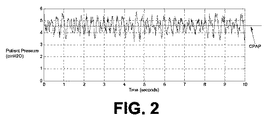
説明する目的で、図2は、従来のバブルCPAPシステムにおける被験者の気道又は気道の近くの圧力のグラフを含む。図2に見られるように、呼吸可能なガスの加圧流を被験者より下流にある水の入った容器に通すことは、従来のバブルCPAPシステムに関連する圧力発生器により供給される平均又は中間圧力レベル近くの圧力の振動を引き起こす。 For illustrative purposes, FIG. 2 includes a graph of the subject's airway or pressure near the airway in a conventional bubble CPAP system. As seen in FIG. 2, passing a pressurized flow of breathable gas through a container of water downstream from the subject is an average or intermediate pressure supplied by a pressure generator associated with a conventional bubble CPAP system. Causes pressure oscillations near the level.
図3は、(図1及び図5から図8に示されると共に、以下に記載される)圧力変動弁24に類似する又はそれと同じ圧力変動弁を実施するシステムにおける、被験者の気道又は気道の近くの圧力のグラフを示す。図3に見られるように、圧力変動弁は、バブルCPAPシステムの圧力の振動に似た確率的変動を引き起こす。バブルCPAPシステムの前記振動に似させるために、前記変動は、確率的(例えばランダム又は疑似ランダム)であると共に、バブルCPAPシステムの振動に類似する大きさを有する。さらに、確率的変動の周波数は、バブルCPAPシステムに見られる振動の周波数に類似している。 FIG. 3 illustrates a subject's airway or near the airway in a system that implements a pressure variation valve similar to or the same as the pressure variation valve 24 (shown in FIGS. 1 and 5-8 and described below). The graph of the pressure of is shown. As can be seen in FIG. 3, the pressure variation valve causes a stochastic variation similar to the pressure oscillations of the bubble CPAP system. In order to resemble the vibration of a bubble CPAP system, the variation is stochastic (eg, random or pseudo-random) and has a magnitude similar to that of a bubble CPAP system. Furthermore, the frequency of the stochastic variation is similar to the frequency of vibrations found in bubble CPAP systems.
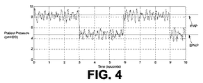
図4は、(図1及び図5から図8に示されると共に、以下に記載される)圧力変動弁24に類似する又はそれと同じ圧力変動弁を実施するシステムにおける、被験者の気道又は気道の近くの圧力のグラフを示す。図4に説明される実施例において、呼吸可能なガスの加圧流は、治療のバイレベルモード(例えばBiPAP(登録商標))で被験者に送出されている。そのため、呼吸可能なガスの加圧流は、被験者の気道の圧力が吸気中の吸気圧力レベルと呼気中の呼気圧力レベルとの間で振動するように発生する。この実施例において、圧力変動弁は、確率的変動が前記吸気圧力レベルと呼気圧力レベルとの間の前記振動の上に重畳されるように構成される。 FIG. 4 shows the subject's airway or near the airway in a system that implements a pressure variation valve similar to or the same as the pressure variation valve 24 (shown in FIGS. 1 and 5-8 and described below). The graph of the pressure of is shown. In the embodiment illustrated in FIG. 4, a pressurized flow of breathable gas is being delivered to the subject in a bi-level mode of therapy (eg, BiPAP®). Thus, a pressurized flow of breathable gas is generated such that the subject's airway pressure oscillates between an inspiratory pressure level during inspiration and an expiratory pressure level during expiration. In this embodiment, the pressure variation valve is configured such that a stochastic variation is superimposed on the vibration between the inspiratory pressure level and the expiratory pressure level.
図1に戻ると、本開示の範囲は、被験者12の気道又は気道の近くに圧力の変動を作り出すことが可能である如何なる機械的要素も圧力変動弁24として検討する。この変動の確率的性質は、圧力変動弁24の機械的構成により生じてもよいし、及び/又は確率的方法での圧力変動弁24の制御により生じてもよい。幾つかの特定の、しかし限定ではない圧力変動弁24の実施例が以下に説明される。
Returning to FIG. 1, the scope of the present disclosure considers any mechanical element capable of creating a pressure fluctuation in or near the airway of the subject 12 as the
ある実施例において、確率的変動の1つ以上のパラメタがユーザにより設定されることができる。例えば、ユーザインタフェース20は、前記1つ以上のパラメタを設定するユーザ選択を受信するように構成されるインタフェースを含む。これら1つ以上のパラメタは、確率的変動の周波数の範囲、確率的変動の平均若しくは中間周波数、確率的変動の大きさの範囲、確率的変動の平均若しくは中間的大きさ、確率的変動が起こる圧力レベルの範囲、前記平均圧力レベルからの最大偏差及び/又は他のパラメタを含んでもよい。
In certain embodiments, one or more parameters of the stochastic variation can be set by the user. For example, the
ある実施例において、圧力変動弁24は、圧力発生器14、導管28及び/又はインタフェース器具30の1つ以上を備える一般的な装置に一体的に含まれる。ある実施例において、圧力変動弁24は、システム10(例えば圧力発生器14と導管28との間、導管28内、導管28とインタフェース器具30との間、インタフェース器具30内、インタフェース器具30より下流及び/又はシステム10における他の場所)に選択的に挿入される別個の構成要素である。圧力変動弁24が圧力発生器14を備える一般的な装置に一体化して含まれている実施例において、圧力変動弁24は、(例えば単独で又は圧力発生器14の他の構成要素と一緒に)呼吸可能なガスの加圧流を加圧する圧力発生器14における構成要素でもよい。
In certain embodiments, the
圧力変動弁24を、他の構成要素と共に一体化して又は別個の構成要素としてシステム10に設けることは、現在のバブルCPAPシステムに勝る様々な強化を提供する。例えばシステム10は、完全な機能的換気でもよいし、及び/又は(例えば圧力発生器14、センサ22及び/又は処理器26を含む)陽圧気道療法システムでもよい。このようなシステムは、従来のバブルCPAPシステムよりもさらに精錬及び/又は洗練される傾向がある。例えば、システム10は、従来のバブルCPAPシステムよりも幅広い治療モード(例えば陽圧気道療法、機械的換気及び/又は他のモード)及び/又は圧力設定に従って動作するように構成可能でもよい。システム10は、被験者12の呼吸パラメタ(例えば呼吸速度、圧力、カプノメトリ、一回換気量、FiO2等)の(例えばセンサ22により生じる出力信号に基づく)電子的監視のために設けられてもよい。これは、従来のバブルCPAPシステムにより達成され得るよりもより正確であり、広範囲の監視である。この監視に基づいて、従来のCPAPシステムでは実施されない治療モード、アラーム及び/又は遮断(shutoff)が実施されてもよい。さらに、このような呼吸パラメタの監視は、治療の効果及び/又は治療の修正を判断する介護人又は治療意思決定者により実施されるのに対し、このような情報は、従来のCPAPシステムが実施される場合は利用可能ではない。システム10は、監視されるパラメタに応じて、呼吸可能なガスの加圧流における酸素富化ガスを被験者12に送出するように構成されてもよい。
Providing the
処理器26は、システム10に情報処理能力を提供するように構成される。そのため、処理器26は、デジタル処理器、アナログ処理器、情報を処理するように設計されるデジタル回路、情報を処理するように設計されるアナログ回路、ステートマシーン及び/又は情報を電子的に処理するための他の機構の1つ以上を含んでもよい。図1において処理器26が単一体として示されたとしても、これは単に説明を目的とするものである。幾つかの実施例において、処理器26は複数の処理ユニットを含んでもよい。これらの処理ユニットは同じ装置内に物理的に置かれてもよいし、又は処理器26が協働して動作する複数の装置からなる処理機能を示してもよい。例えば、ある実施例において、以下の処理器26に起因する一部の機能は、圧力発生器14を備える装置に含まれる1つ以上の構成要素により提供されるのに対し、以下の処理器26に起因する他の機能は、圧力変動弁24を備える別個の装置に含まれる1つ以上の構成要素により提供される。
The
図1に示されるように、処理器26は、1つ以上のコンピュータプログラムモジュールを実施するように構成される。これら1つ以上のコンピュータプログラムモジュールは、ガスパラメタモジュール32、制御モジュール34、呼吸パラメタモジュール36、変動モジュール38及び/又は他のモジュールの1つ以上を含んでもよい。処理器26は、モジュール32、34、36及び/又は38を、ソフトウェア、ハードウェア、ファームウェア、ソフトウェア、ハードウェア及び/又はファームウェアの何らかの組み合わせ、及び/又は処理器26に処理能力を構成するための他の機構により実施するように構成される。
As shown in FIG. 1, the
図1においてモジュール32、34、36及び38が単一の処理ユニット内に共同設置されていると説明されていても、当然のことながら処理器26が複数の処理ユニットを含んでいる実施において、モジュール32、34、36及び/又は38の1つ以上が他のモジュールから離れて置かれてもよい。以下に説明される別々のモジュール32、34、36及び/又は38により提供される機能の記述は、説明を目的とするためであり、モジュール32、34、36及び/又は38の何れかが説明したよりも多い又は少ない機能性を提供してもよいので、限定を意図しているのではない。例えば、モジュール32、34、36及び/又は38の1つ以上が除外されてもよいし、その機能性の幾つか又は全てがモジュール32、34、36及び/又は38の残りのモジュールにより提供されてもよい。他の例として、処理器26は、以下のモジュール32、34、36及び/又は38の1つに起因する機能の幾つか又は全てを行う1つ以上の追加のモジュールを実施するように構成されてもよい。
Although it is described in FIG. 1 that
ガスパラメタモジュール32は、導管28及び/又はインタフェース器具30の1つ以上のガスパラメタ(例えば呼吸可能なガスの加圧流)に関する情報を決定するように構成される。これら1つのガスパラメタはセンサ22の出力信号に基づいて決定される。これら1つ以上のガスパラメタは、圧力、流速、最大流量、組成、湿度、温度、加速度、速度、(例えば質量流量計等において)消散される熱エネルギー及び/又は他のガスパラメタの1つ以上を含んでもよい。ガスパラメタモジュール32により決定されるパラメタは、(例えばユーザインタフェース20を介して)ユーザに示される及び/又はアラーム、遮断及び/又は他の機能のためにトリガパラメタとして使用されてもよい。
The
制御モジュール34は圧力発生器14を制御するように構成される。圧力発生器14を制御することは、呼吸可能なガスの加圧流の1つ以上のパラメタを調整することを含んでいる。この制御モジュール34は、治療モードに従って呼吸可能なガスの加圧流の1つ以上のパラメタを調整するため、被験者12に送出される過度の圧力及び流れを取り除くため、及び/又は他の理由のために、圧力発生器14を制御する。
The
呼吸パラメタモジュール36は、被験者12の呼吸の1つ以上の呼吸パラメタを決定するように構成される。この呼吸パラメタモジュール36は、ガスパラメタモジュール32により及び/又はセンサ22が生成した出力信号から決定される1つ以上のガスパラメタ基づいて1つ以上の呼吸パラメタを決定する。例えば、これら1つ以上の呼吸パラメタは、呼吸速度、吸気流速、吸気期間、呼気流速、呼気期間、一回換気量、呼吸速度、呼吸期間、最大流量、流速曲線形状、圧力曲線形状、呼気−吸気遷移、吸気−呼気遷移、吸気酸素の割合及び/又は他の呼吸パラメタの1つ以上を含んでもよい。呼吸パラメタモジュール36により決定されるパラメタは、アラーム、遮断及び/又は他の機能のためのトリガパラメタとして使用されてもよい。
The
変動モジュール38は、圧力変動弁24の動作を制御するように構成される。この圧力変動弁24の動作を制御することは、確率的変動を開始及び/又は終了すること、確率的変動の周波数の範囲、確率的変動の平均若しくは中間周波数、確率的変動の大きさの範囲、確率的変動の平均若しくは中間的大きさ、確率的変動が起こる圧力レベルの範囲、平均圧力レベルからの最大偏差及び/又は他のパラメタの1つ以上を規定又は設定するために圧力変動弁24の動作を制御することを含む。ある実施例において、変動モジュール38は、(例えばユーザインタフェース20を介して受信されるような)ユーザ選択に従って圧力変動弁24の動作を制御する。
The
図5は、被験者インタフェース回路16に含まれる排気導管40により形成される排気リムを含むシステム10の実施例を説明している。排気導管40は、被験者12がインタフェース器具30に吐いたガスを含む、導管28及び/又はインタフェース器具30から排気されるガスを受け取るように構成される。図5に示される実施例において、排気導管40は前記ガスを圧力発生器14に戻すように伝える。しかしながら、これは限定を目的としているのではない。排気導管40は、前記ガスを圧力発生器14に戻さずに、このガスを別個の装置及び/又は周囲大気に排気してもよい。
FIG. 5 illustrates an embodiment of the
図5の実施例において、圧力変動弁24は、排気導管40内にガスを受け取るためにシステム10内に置かれる。排気導管40を流れるガス流を中断させることにより、圧力変動弁24は、被験者12の気道又は気道の近くに圧力の確率的変動を生じさせるために、インタフェース器具30内の圧力のレベルを効果的に変更する。この構成と図1に示される構成との間にある主な違いは、圧力変動弁24は被験者12より"上流"ではなく、"下流"にあることである。当然のことながら、図5に示される二重リム(dual-limb)システムにおいて、被験者12より下流の圧力変動弁24の記載は、限定を目的としているのではない。二重リムシステムにおいて、圧力変動弁24は、本開示の範囲から外れることなく、(例えば図1の単一リムシステムに示されるように)依然として被験者12より上流に置かれてもよい。さらに、排気導管40と被験者12との間に置かれている圧力変動弁24の描写が限定を目的としているのではない。圧力変動弁24は、インタフェース器具30の排気ポートにある排気リムに、インタフェース器具30と排気導管40との間に、排気導管40内に及び/又は圧力発生器14の内部に置かれてもよい。
In the embodiment of FIG. 5, the
図1に戻って、ある実施例において、圧力の確率的変動は、圧力変動弁24以外の圧力発生器14の構成要素により作り出される及び/又は強化される。例えば、圧力発生器14と関連する送風機又はふいごが圧力の確率的変動を作り出す及び/又は強化されるように制御される。
Returning to FIG. 1, in one embodiment, the stochastic variation in pressure is created and / or enhanced by components of the
このような送風機又はふいご(又は圧力発生器14の他の構成要素)の制御を達成するために、変動モジュール38は、圧力発生器14にある呼吸可能なガスの加圧流に圧力の確率的変動を経験させる圧力発生器14の動作に確率的変動を取り入れるように構成される。変動モジュール38は、前記変動を例えば圧力発生器14に関連付けられる送風機の速度、圧力発生器に関連するモータに供給される電流に取り入れてもよく及び/又は前記変動を圧力発生器14の動作の他の態様に取り入れてもよい。前記変動のパラメタは、変動モジュールによりランダム又は疑似ランダム方法で決定されてもよい。例えば、前記変動の大きさ、方向、周波数、タイミング及び/又は他のパラメタがランダムに又は疑似ランダムに決められてもよい。これら大きさの境界、限界又は他の制限がユーザ選択から得られてもよい。
In order to achieve control of such a blower or bellows (or other components of the pressure generator 14), the
図6は、圧力変動弁24の実施例を説明している。図6に示される実施例において、圧力変動弁24は導管42、ダイヤフラム44、モータ46及び/又は他の構成要素を含んでいる。
FIG. 6 illustrates an embodiment of the
導管42は、第1の端部48及び第2の端部50を含む。導管42は、第1の端部48と第2の端部50との間に流路を形成する。使用中、圧力変動弁24は、呼吸可能なガスの加圧流が第1の端部48と第2の端部50との間にある流路を(例えば被験者から上流又は下流に)通るような呼吸可能なガスの加圧流を被験者の気道に供給するように構成されるシステム内に取り付けられる。
The
ダイヤフラム44は、第1の表面52及び第2の表面54を持つ薄い部材として形成される。ダイヤフラム44は、持つダイヤフラム44のモータ46とのインタフェースにおいて導管42の内部表面に枢動可能なように取り付けられる。第1の表面52及び/又は第2の表面54の形状は、ダイヤフラム44がモータとの枢動部の周りを回転するので、第1の表面52及び/又は第2の表面54が導管42を通るガス流を少なくとも一部ブロックするように、導管42の内部断面に対応する。しかしながら、ダイヤフラム44の薄さによって、ガスは、第1の表面52及び第2の表面が導管42の側壁に向いているとき、比較的スムースに導管42を流れることが可能である。ある実施例において、ダイヤフラム44が弾性的に柔軟な材料から形成される。ある実施例において、ダイヤフラム44の柔軟性は、このダイヤフラム44に電流を流すことにより制御可能である。
モータ46は導管42内にあるダイヤフラム44を回転させるように構成される。これは、被験者の気道又は気道の近くに圧力の確率的変動を生じさせるような方法で、ダイヤフラム44に導管42を通るガス流を中断させる。特に、ダイヤフラム44は導管42内で回転するので、第1の表面52及び/又は第2の表面54は、(その位置に依存して)多かれ少なかれガスをブロックし、それにより確率的変動を引き起こす。当然ながら、ダイヤフラム44の"回転"は必ずしも軸の周りを完全に回っていない。代わりに、ダイヤフラム44の"回転"は、異なる回転方向に行ったり来たりする振動を指してもよい。
ある実施例において、ダイヤフラム44は導管42を通るガス流により曲げられるので、ダイヤフラム44の柔軟性は変動の確率的性質に起因する。ある実施例において、導管42内にあるダイヤフラム44の回転の1つ以上の態様は確率的であり、これは前記変動の確率的性質に起因する。例えば、回転軸、回転速度、回転加速度、回転方向が変化する位置及び/又はダイヤフラム44の回転の態様は、(例えばモータ46の制御及び/又は構造を介して)確率的に変化してもよい。
In one embodiment, the
図7は、圧力変動弁24の実施例を説明している。図7に示される実施例において、圧力変動弁24は、導管56、ふいご58、モータ60及び/又は他の構成要素を含んでいる。
FIG. 7 illustrates an embodiment of the
導管56は、第1の端部62及び第2の端部64を含んでいる。導管56は、第1の端部62と第2の端部64との間に流路を形成する。使用中、圧力変動弁24は、呼吸可能なガスの加圧流が(例えば被験者から上流又は下流に)第1の端部62と第2の端部64との間にある前記流路を通過するような呼吸可能なガスの加圧流を被験者の気道に供給するように構成されるシステム内に取り付けられる。
The
ふいご58は、出力部66からガスを出力するように構成される。ふいご58は、出力部66の反対側にあるふいご58の端部の軸68に沿った長軸方向の運動により、ガスを(示されない入力部を介して)取り込む及び(出力部66を介して)出力するために、膨らんだり縮んだりする。出力部66を介して導管56内にガスを出力することは、この導管56を通るガス流を中断させる傾向があり、それにより被験者の気道又は気道の近くの圧力の変動を引き起こす。
The bellows 58 is configured to output gas from the
モータ60は、出力部66の反対側にあるふいご58の端部を軸68に沿って前後に駆動させるように構成される。ある実施例において、モータ60はふいご58の端部を軸68に沿って前後に駆動させる原動力を供給する磁場を作り出すボイスコイル(voice coil)を含む。ふいご58の不明確な性質及び/又はふいご58から出力されるガスと導管56にあるガスとの相互作用は、圧力変動弁24により引き起こされる被験者の気道又は気道の近くに圧力の変動を確率的にさせる。ある実施例において、駆動モータ60に供給される電流はランダム又は疑似ランダムに変化する。これは、被験者の気道又は気道の近くの圧力の変動の確率的性質に起因する。
The
図8は、被験者の気道に呼吸可能なガスの加圧流を供給する方法70を説明している。以下に示される方法70の動作は、説明を目的としている。幾つかの実施例において、方法70は、記載されていない1つ以上の追加の動作を用いて及び/又は説明した動作の1つ以上を用いずに達成されてもよい。加えて、方法70の動作が図8に説明及び以下に記載されている順番は、限定を目的としているのではない。
FIG. 8 illustrates a
動作72において、呼吸可能なガスの加圧流が発生する。この呼吸可能なガスの加圧流の1つ以上のガスパラメタは、被験者に治療効果をもたらすように制御される。ある実施例において、動作72は、(図1に示されると共に上述される)圧力発生器14に類似又は同じである圧力発生器により行われる。
In
動作74において、呼吸可能なガスの加圧流が被験者の気道に送出される。ある実施例において、動作74は、(図1に示されると共に上述される)被験者インタフェース回路16に類似又は同じである被験者インタフェース回路により行われる。
In
動作76において、圧力変動弁及び/又は圧力発生器は、被験者の気道又は気道の近くに呼吸可能なガスの加圧流の圧力の確率的変動を作り出すように動作する。この圧力変動弁は、(図1及び図5から図7に示されると共に上述される)圧力変動弁24に類似又は同じでもよい。
In
動作78において、前記確率的変動に対する1つ以上のパラメタのユーザ選択が受信される。前記1つ以上のパラメタは、例えば確率的変動の周波数の範囲、確率的変動の平均若しくは中間周波数、確率的変動の大きさの範囲、確率的変動の平均若しくは中間的大きさ、確率的変動が起こる圧力レベルの範囲、平均圧力レベルからの最大偏差、及び/又は他のパラメタの1つ以上を含んでいる。ある実施例において、動作78は、(図1に示されると共に上述される)ユーザインタフェース20に類似又は同じであるユーザインタフェースにより行われる。
At
動作80において、圧力変動弁及び/又は圧力発生器の動作は、受信したユーザ選択に従って調整される。ある実施例において、動作80は(図1に示されると共に上述される)変動モジュール38に類似又は同じである変動モジュールにより行われる。
In
本発明が最も実用的な及び好ましい実施例であると現在考えているものに基づいて、説明を目的として詳細に説明されたとしても、このような詳細は単に説明を目的とするものであること、並びに本発明は開示した実施例に限定されるのではなく、それどころか、付随する請求項の真意及び範囲内にある改良及び等価な配列にも及んでいることを理解すべきである。例えば、本発明は、可能な限り如何なる実施例の1つ以上の特性が他の如何なる実施例の1つ以上の特性と組み合わされ得ることを考慮すると理解すべきである。 Even though the present invention has been described in detail for purposes of illustration based on what is presently considered to be the most practical and preferred embodiment, such details are for illustrative purposes only. It should also be understood that the invention is not limited to the disclosed embodiments, but rather extends to modifications and equivalent arrangements that fall within the spirit and scope of the appended claims. For example, the present invention should be understood in view of the fact that one or more characteristics of any embodiment can be combined with one or more characteristics of any other embodiment as much as possible.
Claims (9)
前記呼吸可能なガスの加圧流の1つ以上のガスパラメタが被験者に治療効果をもたらすような前記呼吸可能なガスの加圧流を発生させるように構成される圧力発生器、
前記圧力発生器から前記被験者の気道に前記呼吸可能なガスの加圧流を送出するように構成される被験者インタフェース回路、及び
前記被験者の気道又は気道の近くに前記呼吸可能なガスの加圧流の圧力の確率的変動を作り出すように構成される圧力変動機構であり、前記圧力変動機構は、処理器、前記処理器を介して実施可能な変動モジュール、並びに(i)圧力変動弁、(ii)前記圧力発生器の構成要素及び(iii)前記圧力変動弁及び前記圧力発生器の構成要素からなる集合から選択される1つ、を有し、前記変動モジュールはさらに、(a)確率的変動の開始及び/又は終了を制御する、並びに(b)前記確率的変動の周波数の範囲、前記確率的変動の平均若しくは中間周波数、前記確率的変動の大きさの範囲、前記確率的変動の平均若しくは中間的大きさ、前記確率的変動が起こる圧力レベルの範囲、及び平均圧力レベルからの最大偏差の1つ以上を定める又は設定するように構成される、前記圧力変動機構
を有するシステム。 In a system configured to provide a pressurized flow of breathable gas to a subject's airway,
A pressure generator configured to generate a pressurized flow of the breathable gas such that one or more gas parameters of the pressurized flow of breathable gas provide a therapeutic effect to the subject;
A subject interface circuit configured to deliver a pressurized flow of breathable gas from the pressure generator to the subject's airway; and a pressure of the pressurized flow of breathable gas near the subject's airway or airway A pressure variation mechanism configured to produce a stochastic variation of : a processor, a variation module operable via the processor, and (ii) a pressure variation valve; A pressure generator component and (iii) one selected from the group consisting of the pressure variation valve and the pressure generator component, the variation module further comprising: (a) the onset of stochastic variation And / or controlling termination, and (b) a range of the frequency of the stochastic variation, an average or intermediate frequency of the stochastic variation, a range of the magnitude of the stochastic variation, and the stochastic variation The pressure variation mechanism configured to determine or set one or more of an average or intermediate magnitude of the pressure, a range of pressure levels where the stochastic variation occurs, and a maximum deviation from the average pressure level Having a system.
前記呼吸可能なガスの加圧流の1つ以上のガスパラメタが前記被験者に治療効果をもたらすような前記呼吸可能なガスの加圧流を発生させる手段、
前記被験者の気道に前記呼吸可能なガスの加圧流を送出する手段、並びに
前記被験者の気道又は気道の近くに前記呼吸可能なガスの加圧流の圧力の確率的変動を作り出す手段であり、前記確率的変動を作り出す手段は、処理器、前記処理器を介して実施可能な変動モジュール、並びに(i)圧力変動弁、(ii)圧力発生器の構成要素及び(iii)前記圧力変動弁及び前記圧力発生器の構成要素からなる集合から選択される1つ、を有し、前記変動モジュールはさらに、(a)確率的変動の開始及び/又は終了を制御する、並びに(b)前記確率的変動の周波数の範囲、前記確率的変動の平均若しくは中間周波数、前記確率的変動の大きさの範囲、前記確率的変動の平均若しくは中間的大きさ、前記確率的変動が起こる圧力レベルの範囲、及び平均圧力レベルからの最大偏差の1つ以上を定める又は設定するように構成される、前記確率的変動を作り出す手段、
を有するシステム。 In a system configured to provide a pressurized flow of breathable gas to a subject's airway,
Means for generating a pressurized flow of the breathable gas such that one or more gas parameters of the pressurized flow of breathable gas have a therapeutic effect on the subject;
Means for delivering a pressurized flow of the breathable gas to the subject's airway , and means for creating a stochastic variation in the pressure of the pressurized flow of breathable gas in or near the subject's airway , the probability The means for creating a dynamic variation includes a processor, a variation module operable through the processor, and (i) a pressure variation valve, (ii) a component of the pressure generator, and (iii) the pressure variation valve and the pressure. The variation module further comprising: (a) controlling the start and / or termination of the stochastic variation; and (b) the stochastic variation of the generator component. A range of frequencies, an average or intermediate frequency of the stochastic variation, a range of the magnitude of the stochastic variation, an average or intermediate magnitude of the stochastic variation, a range of pressure levels at which the stochastic variation occurs, And means for creating the stochastic variation configured to define or set one or more of a maximum deviation from the average pressure level;
Having a system.
Applications Claiming Priority (3)
| Application Number | Priority Date | Filing Date | Title |
|---|---|---|---|
| US37335410P | 2010-08-13 | 2010-08-13 | |
| US61/373,354 | 2010-08-13 | ||
| PCT/IB2011/053581 WO2012020387A1 (en) | 2010-08-13 | 2011-08-11 | System and method for providing a pressurized flow of breathable gas to the airway of a subject with stochastic fluctuations |
Publications (3)
| Publication Number | Publication Date |
|---|---|
| JP2013533087A JP2013533087A (en) | 2013-08-22 |
| JP2013533087A5 JP2013533087A5 (en) | 2014-09-18 |
| JP5872554B2 true JP5872554B2 (en) | 2016-03-01 |
Family
ID=44677988
Family Applications (1)
| Application Number | Title | Priority Date | Filing Date |
|---|---|---|---|
| JP2013523695A Expired - Fee Related JP5872554B2 (en) | 2010-08-13 | 2011-08-11 | System and method for providing a pressurized flow of breathable gas to a subject's airway using stochastic variation |
Country Status (8)
| Country | Link |
|---|---|
| US (1) | US20130133654A1 (en) |
| EP (1) | EP2603266B1 (en) |
| JP (1) | JP5872554B2 (en) |
| CN (1) | CN103068428B (en) |
| BR (1) | BR112013003293A2 (en) |
| IN (1) | IN2013CN01313A (en) |
| RU (1) | RU2584806C2 (en) |
| WO (1) | WO2012020387A1 (en) |
Families Citing this family (10)
| Publication number | Priority date | Publication date | Assignee | Title |
|---|---|---|---|---|
| WO2013175345A1 (en) * | 2012-05-22 | 2013-11-28 | Koninklijke Philips N.V. | Cough assistance and measurement system and method cross-reference to related applications |
| CN104363943A (en) * | 2012-05-22 | 2015-02-18 | 皇家飞利浦有限公司 | System and method for pressure support therapy with shaped airflow |
| US20140000606A1 (en) * | 2012-07-02 | 2014-01-02 | Nellcor Puritan Bennett Llc | Methods and systems for mimicking fluctuations in delivered flow and/or pressure during ventilation |
| US10335566B2 (en) | 2013-08-09 | 2019-07-02 | Advanced Cooling Therapy, Inc. | Systems and methods for providing ventilation |
| EP3030302B1 (en) * | 2013-09-04 | 2023-02-22 | Fisher&Paykel Healthcare Limited | Improvements to flow therapy |
| EP3116578B1 (en) * | 2014-03-11 | 2019-05-08 | Koninklijke Philips N.V. | Compact dual limb diaphragm valve system |
| WO2016079703A1 (en) * | 2014-11-20 | 2016-05-26 | Koninklijke Philips N.V. | Non-invasive ventilation with high frequency oscillations |
| BR112017015194A2 (en) | 2015-01-16 | 2018-03-13 | Western Michigan University Research Foundation | double-pressure breathing assist device |
| US11951251B2 (en) | 2018-04-05 | 2024-04-09 | Anna John | Dual-pressure respiratory assistance device |
| JP2022506482A (en) * | 2018-11-02 | 2022-01-17 | ユニバーシティ・オブ・シンシナティ | Pulsating airway positive pressure device and usage |
Family Cites Families (12)
| Publication number | Priority date | Publication date | Assignee | Title |
|---|---|---|---|---|
| US4592349A (en) * | 1981-08-10 | 1986-06-03 | Bird F M | Ventilator having an oscillatory inspiratory phase and method |
| US5165398A (en) * | 1989-12-08 | 1992-11-24 | Bird F M | Ventilator and oscillator for use therewith and method |
| US6257234B1 (en) * | 1998-08-21 | 2001-07-10 | Respironics, Inc. | Apparatus and method for determining respiratory mechanics of a patient and for controlling a ventilator based thereon |
| US6708690B1 (en) * | 1999-09-03 | 2004-03-23 | Respironics, Inc. | Apparatus and method for providing high frequency variable pressure to a patient |
| RU2164805C1 (en) * | 1999-10-08 | 2001-04-10 | Открытое акционерное общество Акционерная компания "Туламашзавод" | Device for making respiratory exercises |
| SE0002849D0 (en) * | 2000-08-08 | 2000-08-08 | Siemens Elema Ab | ventilator |
| US7478634B2 (en) * | 2002-09-17 | 2009-01-20 | Jam Mohammad R | Respiratory booster machine and method for enhancing ventilation |
| US6929007B2 (en) * | 2003-09-08 | 2005-08-16 | J.H. Emerson Company | Insufflation-exsufflation system with percussive assist for removal of broncho-pulmonary secretions |
| SE529328C2 (en) * | 2005-11-15 | 2007-07-10 | Johan Stenberg | Control system and method for controlling electromagnetically driven pumps |
| ITMI20061755A1 (en) * | 2006-09-14 | 2008-03-15 | Milano Politecnico | RESPIRATORY SUPPORT SYSTEM AND NON-INVASIVE DETECTION OF ALVEOLAR DERECLUTATION FOR PATIENTS WITH RESPIRATORY INSUFFICIENCIES |
| US8051854B2 (en) | 2006-09-15 | 2011-11-08 | Comedica Incorporated | Continuous high-frequency oscillation breathing treatment apparatus |
| CN103357094B (en) | 2008-04-10 | 2015-10-28 | 西雅图儿童医院d/b/a西雅图儿童研究所 | Utilize the broadband of bubble, low frequency, high-amplitude, long duration, oscillating airway pressure breathing apparatus |
-
2011
- 2011-08-11 BR BR112013003293A patent/BR112013003293A2/en not_active IP Right Cessation
- 2011-08-11 RU RU2013110816/14A patent/RU2584806C2/en not_active IP Right Cessation
- 2011-08-11 JP JP2013523695A patent/JP5872554B2/en not_active Expired - Fee Related
- 2011-08-11 WO PCT/IB2011/053581 patent/WO2012020387A1/en active Application Filing
- 2011-08-11 US US13/814,598 patent/US20130133654A1/en not_active Abandoned
- 2011-08-11 CN CN201180039029.5A patent/CN103068428B/en active Active
- 2011-08-11 IN IN1313CHN2013 patent/IN2013CN01313A/en unknown
- 2011-08-11 EP EP11761137.6A patent/EP2603266B1/en active Active
Also Published As
| Publication number | Publication date |
|---|---|
| BR112013003293A2 (en) | 2019-09-24 |
| RU2584806C2 (en) | 2016-05-20 |
| IN2013CN01313A (en) | 2015-08-07 |
| WO2012020387A1 (en) | 2012-02-16 |
| CN103068428A (en) | 2013-04-24 |
| US20130133654A1 (en) | 2013-05-30 |
| EP2603266B1 (en) | 2017-05-24 |
| JP2013533087A (en) | 2013-08-22 |
| RU2013110816A (en) | 2014-09-20 |
| CN103068428B (en) | 2016-01-13 |
| EP2603266A1 (en) | 2013-06-19 |
Similar Documents
| Publication | Publication Date | Title |
|---|---|---|
| JP5872554B2 (en) | System and method for providing a pressurized flow of breathable gas to a subject's airway using stochastic variation | |
| JP6175056B2 (en) | System and method for limited flow respiratory therapy | |
| US20200157090A1 (en) | Non-invasive ventilation with high frequency oscillations | |
| JP6173320B2 (en) | Non-invasive ventilation measurement | |
| US9833583B2 (en) | System and method for adjusting tidal volume of a self-ventilation subject | |
| US9642976B2 (en) | Systems and methods for intra-pulmonary percussive ventilation integrated in a ventilator | |
| JP6316273B2 (en) | System and method for controlling insufflation pressure during insufflation | |
| JP6133842B2 (en) | System and method for treating sleep apnea | |
| JP2013508063A (en) | System and method for treating dysphagia | |
| US20150075529A1 (en) | System and method for pressure support therapy with shaped airflow | |
| JP2013526327A (en) | System and method for detecting sleep onset of a subject based on a response to a respiratory trigger | |
| JP2016523586A5 (en) | ||
| JP2015502212A (en) | System and method for using partial CO2 rebreathing integrated in a ventilator and its measurement to determine non-invasive cardiac output | |
| JP6552116B2 (en) | Critical care ventilator with mouthpiece ventilation | |
| JP6384965B2 (en) | Method and apparatus for increasing expiratory airflow | |
| US20150306325A1 (en) | System for providing pressure pulses to the airway of a subject | |
| JP2016501660A (en) | System and method for limiting flow and / or pressure compensation during restricted flow respiratory therapy |
Legal Events
| Date | Code | Title | Description |
|---|---|---|---|
| A521 | Written amendment |
Free format text: JAPANESE INTERMEDIATE CODE: A523 Effective date: 20140730 |
|
| A621 | Written request for application examination |
Free format text: JAPANESE INTERMEDIATE CODE: A621 Effective date: 20140730 |
|
| A977 | Report on retrieval |
Free format text: JAPANESE INTERMEDIATE CODE: A971007 Effective date: 20150515 |
|
| A131 | Notification of reasons for refusal |
Free format text: JAPANESE INTERMEDIATE CODE: A131 Effective date: 20150519 |
|
| A521 | Written amendment |
Free format text: JAPANESE INTERMEDIATE CODE: A523 Effective date: 20150813 |
|
| TRDD | Decision of grant or rejection written | ||
| A01 | Written decision to grant a patent or to grant a registration (utility model) |
Free format text: JAPANESE INTERMEDIATE CODE: A01 Effective date: 20151215 |
|
| A61 | First payment of annual fees (during grant procedure) |
Free format text: JAPANESE INTERMEDIATE CODE: A61 Effective date: 20160113 |
|
| R150 | Certificate of patent or registration of utility model |
Ref document number: 5872554 Country of ref document: JP Free format text: JAPANESE INTERMEDIATE CODE: R150 |
|
| LAPS | Cancellation because of no payment of annual fees |