JP5871750B2 - Mobile communication system, radio base station and mobile station - Google Patents
Mobile communication system, radio base station and mobile station Download PDFInfo
- Publication number
- JP5871750B2 JP5871750B2 JP2012187811A JP2012187811A JP5871750B2 JP 5871750 B2 JP5871750 B2 JP 5871750B2 JP 2012187811 A JP2012187811 A JP 2012187811A JP 2012187811 A JP2012187811 A JP 2012187811A JP 5871750 B2 JP5871750 B2 JP 5871750B2
- Authority
- JP
- Japan
- Prior art keywords
- radio base
- base station
- bearer
- radio
- mobile station
- Prior art date
- Legal status (The legal status is an assumption and is not a legal conclusion. Google has not performed a legal analysis and makes no representation as to the accuracy of the status listed.)
- Active
Links
- 238000010295 mobile communication Methods 0.000 title claims description 38
- 238000013507 mapping Methods 0.000 claims description 10
- 230000002776 aggregation Effects 0.000 claims description 8
- 238000004220 aggregation Methods 0.000 claims description 8
- 230000011664 signaling Effects 0.000 claims description 5
- 238000000034 method Methods 0.000 description 6
- 238000012986 modification Methods 0.000 description 5
- 230000004048 modification Effects 0.000 description 5
- 230000008569 process Effects 0.000 description 5
- 238000012546 transfer Methods 0.000 description 5
- 238000004891 communication Methods 0.000 description 4
- 238000012937 correction Methods 0.000 description 4
- 238000010586 diagram Methods 0.000 description 4
- 238000005259 measurement Methods 0.000 description 3
- 230000004044 response Effects 0.000 description 3
- 238000012545 processing Methods 0.000 description 2
- 241001522296 Erithacus rubecula Species 0.000 description 1
- 239000000969 carrier Substances 0.000 description 1
- 230000006835 compression Effects 0.000 description 1
- 238000007906 compression Methods 0.000 description 1
- 230000006870 function Effects 0.000 description 1
- 230000007774 longterm Effects 0.000 description 1
Images


Classifications
-
- H—ELECTRICITY
- H04—ELECTRIC COMMUNICATION TECHNIQUE
- H04W—WIRELESS COMMUNICATION NETWORKS
- H04W72/00—Local resource management
-
- H—ELECTRICITY
- H04—ELECTRIC COMMUNICATION TECHNIQUE
- H04L—TRANSMISSION OF DIGITAL INFORMATION, e.g. TELEGRAPHIC COMMUNICATION
- H04L5/00—Arrangements affording multiple use of the transmission path
- H04L5/0001—Arrangements for dividing the transmission path
- H04L5/0003—Two-dimensional division
- H04L5/0005—Time-frequency
- H04L5/0007—Time-frequency the frequencies being orthogonal, e.g. OFDM(A), DMT
- H04L5/001—Time-frequency the frequencies being orthogonal, e.g. OFDM(A), DMT the frequencies being arranged in component carriers
-
- H—ELECTRICITY
- H04—ELECTRIC COMMUNICATION TECHNIQUE
- H04W—WIRELESS COMMUNICATION NETWORKS
- H04W72/00—Local resource management
- H04W72/20—Control channels or signalling for resource management
-
- H—ELECTRICITY
- H04—ELECTRIC COMMUNICATION TECHNIQUE
- H04W—WIRELESS COMMUNICATION NETWORKS
- H04W16/00—Network planning, e.g. coverage or traffic planning tools; Network deployment, e.g. resource partitioning or cells structures
- H04W16/24—Cell structures
- H04W16/32—Hierarchical cell structures
-
- H—ELECTRICITY
- H04—ELECTRIC COMMUNICATION TECHNIQUE
- H04W—WIRELESS COMMUNICATION NETWORKS
- H04W76/00—Connection management
- H04W76/10—Connection setup
- H04W76/11—Allocation or use of connection identifiers
-
- H—ELECTRICITY
- H04—ELECTRIC COMMUNICATION TECHNIQUE
- H04W—WIRELESS COMMUNICATION NETWORKS
- H04W76/00—Connection management
- H04W76/10—Connection setup
- H04W76/15—Setup of multiple wireless link connections
-
- H—ELECTRICITY
- H04—ELECTRIC COMMUNICATION TECHNIQUE
- H04W—WIRELESS COMMUNICATION NETWORKS
- H04W88/00—Devices specially adapted for wireless communication networks, e.g. terminals, base stations or access point devices
- H04W88/08—Access point devices
-
- H—ELECTRICITY
- H04—ELECTRIC COMMUNICATION TECHNIQUE
- H04W—WIRELESS COMMUNICATION NETWORKS
- H04W88/00—Devices specially adapted for wireless communication networks, e.g. terminals, base stations or access point devices
- H04W88/16—Gateway arrangements
Landscapes
- Engineering & Computer Science (AREA)
- Signal Processing (AREA)
- Computer Networks & Wireless Communication (AREA)
- Mobile Radio Communication Systems (AREA)
Description
本発明は、移動通信システム、無線基地局及び移動局に関する。 The present invention relates to a mobile communication system, a radio base station, and a mobile station.
LTE(Long Term Evolution)方式のRelease-10において、図8(a)に示すように、20MHzを超える広帯域通信(例えば、100Hzの通信)を実現するために、同一の無線基地局eNB配下の複数のCC(Component Carrier:コンポーネントキャリア)を束ねて通信を行うCA(Carrier Aggregation:キャリアアグリゲーション)が導入された。 In Release-10 of LTE (Long Term Evolution) method, as shown in FIG. 8A, in order to realize broadband communication exceeding 20 MHz (for example, communication at 100 Hz), a plurality of subordinates under the same radio base station eNB CA (Carrier Aggregation) that performs communication by bundling CCs (Component Carriers) is introduced.
その後、LTE方式のRelease-12以降で、「Small Cell enhancement」が提案され、従来よりも更に柔軟なネットワークアーキテクチャの1つとして、異なる無線基地局eNB配下のCC(セル)を束ねて通信を行う「Inter-site CA」の導入が検討されている(図8(b)参照)。 Thereafter, "Small Cell enhancement" was proposed in LTE Release 12 or later, and communication is performed by bundling CCs (cells) under different radio base stations eNB as one of more flexible network architectures than before. The introduction of “Inter-site CA” is being studied (see FIG. 8B).
従来のLTE方式では、図9に示すように、1つのEPS(Evolved Packet System)ベアラと1つの無線ベアラとを関連付けるように構成されている。 As shown in FIG. 9, the conventional LTE scheme is configured to associate one EPS (Evolved Packet System) bearer with one radio bearer.
具体的には、図9に示すように、EPSベアラは、1つの無線ベアラと1つのS1ベアラと1つのS5/S8ベアラとによって構成されている。 Specifically, as illustrated in FIG. 9, the EPS bearer includes one radio bearer, one S1 bearer, and one S5 / S8 bearer.
ここで、無線ベアラは、移動局UEと無線基地局eNBとの間で設定されており、S1ベアラは、無線基地局eNBとゲートウェイ装置S-GWとの間で設定されており、S5/S8ベアラは、ゲートウェイ装置S-GWとゲートウェイ装置P-GWとの間で設定されている。 Here, the radio bearer is set between the mobile station UE and the radio base station eNB, the S1 bearer is set between the radio base station eNB and the gateway device S-GW, and S5 / S8. The bearer is set between the gateway device S-GW and the gateway device P-GW.
すなわち、EPSベアラは、移動局UEとゲートウェイ装置P-GWとの間で設定されているベアラである。 That is, the EPS bearer is a bearer set between the mobile station UE and the gateway device P-GW.
しかしながら、従来のLTE方式では、「Inter-site CA」が用いられるケースのベアラ構成を、どのようにすべきかについて規定されていないという問題点があった。 However, the conventional LTE system has a problem in that it is not specified how to configure the bearer configuration in the case where “Inter-site CA” is used.
そこで、本発明は、上述の課題に鑑みてなされたものであり、「Inter-site CA」が用いられるケースのベアラ構成を適切に規定することができる移動通信システム、無線基地局及び移動局を提供することを目的とする。 Therefore, the present invention has been made in view of the above-described problems, and a mobile communication system, a radio base station, and a mobile station that can appropriately define a bearer configuration in a case where “Inter-site CA” is used. The purpose is to provide.
本発明の第1の特徴は、移動局が複数の無線基地局配下のセルを介してキャリアアグリゲーションを行うことができるように構成されている移動通信システムであって、前記複数の無線基地局内のアンカー無線基地局が、前記移動局とゲートウェイ装置との間で設定されている1つのベアラと、該移動局と前記複数の無線基地局との間で設定されている複数の無線ベアラとを関連付けるように構成されていることを要旨とする。 A first feature of the present invention is a mobile communication system configured such that a mobile station can perform carrier aggregation via cells under the control of a plurality of radio base stations. The anchor radio base station associates one bearer set up between the mobile station and the gateway device and a plurality of radio bearers set up between the mobile station and the plurality of radio base stations It is summarized as follows.
本発明の第2の特徴は、移動局が複数の無線基地局配下のセルを介してキャリアアグリゲーションを行うことができるように構成されている移動通信システムにおいて、該複数の無線基地局内のアンカー無線基地局として動作することができる無線基地局であって、前記移動局とゲートウェイ装置との間で設定されている1つのベアラと、該移動局と前記複数の無線基地局との間で設定されている複数の無線ベアラとを関連付けるように構成されていることを要旨とする。 A second feature of the present invention is that, in a mobile communication system configured to allow a mobile station to perform carrier aggregation via cells under the control of a plurality of radio base stations, an anchor radio in the plurality of radio base stations is provided. A radio base station that can operate as a base station, and is set between one bearer set between the mobile station and the gateway device, and the mobile station and the plurality of radio base stations. The gist of the present invention is that the wireless bearers are associated with each other.
本発明の第3の特徴は、複数の無線基地局配下のセルを介してキャリアアグリゲーションを行うことができるように構成されている移動局であって、ゲートウェイ装置との間で設定されている1つのベアラと、前記複数の無線基地局との間で設定されている複数の無線ベアラとを関連付けるように構成されていることを要旨とする。
A third feature of the present invention is a mobile station configured to be able to perform carrier aggregation via cells under a plurality of radio base stations, and is set with a
以上説明したように、本発明によれば、「Inter-site CA」が用いられる場合のベアラ構成を適切に規定することができる移動通信システム、無線基地局及び移動局を提供することができる。 As described above, according to the present invention, it is possible to provide a mobile communication system, a radio base station, and a mobile station that can appropriately define a bearer configuration when “Inter-site CA” is used.
(本発明の第1の実施形態に係る移動通信システム)
図1乃至図6を参照して、本発明の第1の実施形態に係る移動通信システムについて説明する。
(Mobile communication system according to the first embodiment of the present invention)
With reference to FIG. 1 thru | or FIG. 6, the mobile communication system which concerns on the 1st Embodiment of this invention is demonstrated.
本実施形態に係る移動通信システムは、LTE方式の移動通信システムであって、「Inter-site CA」を適用することができるように構成されている。 The mobile communication system according to the present embodiment is an LTE mobile communication system, and is configured to be able to apply “Inter-site CA”.
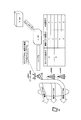
図1に示すように、本実施形態に係る移動通信システムは、ゲートウェイ装置P-GWと、ゲートウェイ装置S-GWと、無線基地局eNB#1〜#3とを具備している。 As shown in FIG. 1, the mobile communication system according to the present embodiment includes a gateway device P-GW, a gateway device S-GW, and radio base stations eNB # 1 to # 3.
例えば、無線基地局eNB#1配下のセル#1は、マクロセルであり、無線基地局eNB#2〜#3配下のセル#2〜#3は、ファントムセル(スモールセル)である。
For example, the
また、無線基地局eNB#1〜#3配下のセル#1〜#3のカバレッジエリアは、少なくとも一部で重なるように配置されているものとする。
In addition, it is assumed that the coverage areas of the
本実施形態に係る移動通信システムでは、1つのEPSベアラと複数の無線ベアラとを関連付ける「Bearer Sharing」を適用することができるように構成されている。 The mobile communication system according to the present embodiment is configured to be able to apply “Bearer Sharing” that associates one EPS bearer with a plurality of radio bearers.
ここで、図1の例では、無線基地局eNB#1〜#3のうち、無線基地局eNB#1が、アンカー無線基地局eNBであり、移動局UEについて、1つのEPSベアラ#Bと、複数の無線ベアラ#3〜#5とを関連付けるように構成されている。
Here, in the example of FIG. 1, the radio base station eNB # 1 is the anchor radio base station eNB among the radio base stations eNB # 1 to # 3, and one EPS bearer #B for the mobile station UE, A plurality of
なお、アンカー無線基地局eNBは、マクロセルを管理する無線基地局eNB#1であってもよいし、その他の無線基地局eNBであってもよい。また、本実施形態に係る移動通信システムにおいて、或いは、本実施形態に係る移動通信システム内の所定エリアにおいて、各移動局UEに対して、アンカー無線基地局eNBは、1つだけ存在してもよいし、複数存在してもよい。 Note that the anchor radio base station eNB may be the radio base station eNB # 1 that manages the macro cell, or may be another radio base station eNB. Also, in the mobile communication system according to the present embodiment or in a predetermined area in the mobile communication system according to the present embodiment, only one anchor radio base station eNB exists for each mobile station UE. There may be more than one.
ここで、アンカー無線基地局eNBとして機能している無線基地局eNB#1は、図1に示すように、移動局UEごとに、1つのEPSベアラの識別子と複数の無線ベアラの識別子と複数の無線基地局eNBの識別子とを関連付けるマッピングテーブルを用いて、上述の関連付けを行うように構成されていてもよい。 Here, the radio base station eNB # 1 functioning as the anchor radio base station eNB, as shown in FIG. 1, for each mobile station UE, an identifier of one EPS bearer, an identifier of a plurality of radio bearers, and a plurality of identifiers The above-described association may be performed using a mapping table that associates the identifier of the radio base station eNB.
図1の例では、かかるマッピングテーブルは、1つのEPSベアラの識別子(#A)と複数の無線ベアラの識別子(#1/#2)と複数の無線基地局eNBの識別子(#m/#n)とを関連付けている。 In the example of FIG. 1, the mapping table includes one EPS bearer identifier (#A), a plurality of radio bearer identifiers (# 1 / # 2), and a plurality of radio base station eNB identifiers (# m / # n). ).
また、図1の例では、かかるマッピングテーブルは、1つのEPSベアラの識別子(#B)と複数の無線ベアラの識別子(#3〜#5)と複数の無線基地局eNBの識別子(#1〜#3)とを関連付けている。 In the example of FIG. 1, the mapping table includes one EPS bearer identifier (#B), a plurality of radio bearer identifiers (# 3 to # 5), and a plurality of radio base station eNB identifiers (# 1 to # 1). # 3).
かかる場合、図2に示すように、上りリンクにおいて、無線ベアラ#3のデータは、無線基地局eNB#1配下のセル#1を介して、移動局UEから無線基地局eNB#1に送信されるように構成されている。
In this case, as shown in FIG. 2, in the uplink, the data of the
また、図2に示すように、上りリンクにおいて、無線ベアラ#4のデータは、無線基地局eNB#2配下のセル#2を介して、移動局UEから無線基地局eNB#1に送信されるように構成されている。
Also, as shown in FIG. 2, in the uplink, the data of the
さらに、図2に示すように、上りリンクにおいて、無線ベアラ#5のデータは、無線基地局eNB#3配下のセル#3を介して、移動局UEから無線基地局eNB#1に送信されるように構成されている。
Further, as shown in FIG. 2, in the uplink, the data of the
同様に、図2に示すように、下りリンクにおいて、無線ベアラ#3のデータは、無線基地局eNB#1配下のセル#1を介して、無線基地局eNB#1から移動局UEに送信されるように構成されている。
Similarly, as shown in FIG. 2, in the downlink, the data of the
また、図2に示すように、下りリンクにおいて、無線ベアラ#4のデータは、無線基地局eNB#2配下のセル#2を介して、無線基地局eNB#2から移動局UEに送信されるように構成されている。
Also, as shown in FIG. 2, in the downlink, the data of the
さらに、図2に示すように、下りリンクにおいて、無線ベアラ#5のデータは、無線基地局eNB#3配下のセル#3を介して、無線基地局eNB#3から移動局UEに送信されるように構成されている。
Further, as shown in FIG. 2, in the downlink, the data of the
ここで、無線ベアラ#4は、移動局UEと無線基地局eNB#2との間で終端するように構成されていてもよいし、無線基地局eNB#2を介して移動局UEと無線基地局eNB#1との間で終端するように構成されていてもよい。
Here, the
同様に、無線ベアラ#5は、移動局UEと無線基地局eNB#3との間で終端するように構成されていてもよいし、無線基地局eNB#3を介して移動局UEと無線基地局eNB#1との間で終端するように構成されていてもよい。
Similarly, the
また、アンカー無線基地局eNBとして機能している無線基地局eNB#1は、下りリンクにおいて、S1ベアラを介して受信した移動局UE宛てのデータを、セル#1〜#3用のデータに分割して、無線ベアラ#3〜#5を介して、移動局UEに送信するように構成されている。
Also, the radio base station eNB # 1 functioning as the anchor radio base station eNB divides the data addressed to the mobile station UE received via the S1 bearer into data for
また、アンカー無線基地局eNBとして機能している無線基地局eNB#1は、上りリンクにおいて、無線ベアラ#3〜#5を介して受信したセル#1〜#3用のデータに対して順序補正(reordering)処理を施して、S1ベアラに送信するように構成されている。
Also, the radio base station eNB # 1 functioning as the anchor radio base station eNB corrects the order of the data for the
一方、移動局UEは、下りリンクにおいて、無線ベアラ#3〜#5を介して受信したセル#1〜#3用のデータに対して順序補正処理を施すように構成されている。
On the other hand, the mobile station UE is configured to perform an order correction process on data for
また、移動局UEは、上りリンクにおいて、送信すべきデータを、セル#1〜#3用のデータに分割して、無線ベアラ#3〜#5を介して、無線基地局eNB#1〜#3に送信するように構成されている。
Also, the mobile station UE divides data to be transmitted into data for
なお、アンカー無線基地局eNBとして機能している無線基地局eNB#1は、個別シグナリングによって、移動局UEに対して、上述の関連付けを行うための情報を通知するように構成されていてもよい。
Note that the radio base
ここで、アンカー無線基地局eNBとして機能している無線基地局eNB#1は、個別シグナリングとして、RRC(Radio Resource Control)メッセージによって、例えば、「RRC connection reconfiguration」等によって、移動局UEに対して、上述の関連付けを行うための情報を通知するように構成されていてもよい。
Here, the radio base
また、アンカー無線基地局eNBとして機能している無線基地局eNB#1は、上述の関連付けを行うための情報として、上述のマッピングテーブルの内容(図1参照)について通知するように構成されていてもよい。
Also, the radio base
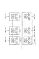
具体的には、図3に示すように、移動局UE及び無線基地局eNB#1〜#3は、無線ベアラごとに、MAC(Media Access Control)エンティティと、RLC(Radio Link Control)エンティティと、PDCP(Packet Data Convergence Protocol)エンティティとを具備している。
Specifically, as illustrated in FIG. 3, the mobile station UE and the radio base
ここで、アンカー無線基地局eNBとして機能している無線基地局eNB#1は、PDCPエンティティとして、「Master PDCPエンティティ」を具備している。
Here, the radio base
これに対して、アンカー無線基地局eNB以外の無線基地局eNB#2〜#3は、PDCPエンティティとして、「Slave PDCPエンティティ」を具備している。
On the other hand, the radio base
なお、移動局UEは、PDCPエンティティとして、「Master PDCPエンティティ」及び「Slave PDCPエンティティ」を具備している。 Note that the mobile station UE includes a “Master PDCP entity” and a “Slave PDCP entity” as PDCP entities.
ここで、「Master PDCPエンティティ」は、無線ベアラ#3に対応するものであり、「Slave PDCPエンティティ」は、無線ベアラ#4〜#5に対応するものである。
Here, “Master PDCP entity” corresponds to
なお、1つのEPSベアラに複数の無線ベアラ#3〜#5が関連付けられている場合に、各無線基地局eNB#1〜#3においてPDCPエンティティが独立して動作するように構成されていると、上りリンク及び下りリンクにおいて、かかるEPSベアラを介して送受信されるPDCP-PDU(Protocol Data Unit)に対する順序補正処理を行うことができない。
When a plurality of
そのため、「Master PDCPエンティティ」は、1つ又は複数の「Slave PDCPエンティティ」を統括するように構成されていてもよい。 Therefore, the “Master PDCP entity” may be configured to control one or a plurality of “Slave PDCP entities”.
具体的には、「Master PDCPエンティティ」は、かかるEPSベアラを介して送受信されるPDCP-PDUに対して、ヘッダ圧縮やセキュリティ管理や「UL/DL PDCP SN(シーケンス番号)」のハンドリング等を行うように構成されている。 Specifically, the “Master PDCP entity” performs header compression, security management, “UL / DL PDCP SN (sequence number)” handling, and the like for PDCP-PDUs transmitted and received via the EPS bearer. It is configured as follows.
また、「Master PDCPエンティティ」の機能の一部を「Slave PDCPエンティティ」が担ってもよい。 Further, a part of the function of “Master PDCP entity” may be performed by “Slave PDCP entity”.
また、「Master PDCPエンティティ」は、ラウンドロビンによって、下りリンクにおいて当該EPSベアラを介して送受信されるPDCP-PDUを「Slave PDCPエンティティ」に配分するように構成されていてもよいし、無線品質に基づく重み付けを考慮して、下りリンクにおいて当該EPSベアラを介して送受信されるPDCP-PDUを「Slave PDCPエンティティ」に配分するように構成されていてもよい。 Further, the “Master PDCP entity” may be configured to distribute PDCP-PDUs transmitted / received via the EPS bearer in the downlink to the “Slave PDCP entity” by round robin. In consideration of weighting based on PDCP-PDUs transmitted and received via the EPS bearer in the downlink, the PDCP-PDU may be allocated to “Slave PDCP entities”.
或いは、各無線基地局eNBにおける輻輳状態や処理量等によって配分が決定されてもよい。ここで、処理量は、接続している移動局UEの数やCPU使用率やバッファ使用率や設定されているベアラの数やnon-DRX比率等で表現されてもよい。 Alternatively, the distribution may be determined according to a congestion state, a processing amount, or the like in each radio base station eNB. Here, the processing amount may be expressed by the number of connected mobile stations UE, the CPU usage rate, the buffer usage rate, the number of set bearers, the non-DRX ratio, or the like.
「Slave PDCPエンティティ」は、「Master PDCPエンティティ」から受け取ったPDCP-PDU(下りリンクデータ)を、RLCエンティティに対して渡すように構成されている。 The “Slave PDCP entity” is configured to pass the PDCP-PDU (downlink data) received from the “Master PDCP entity” to the RLC entity.
なお、「Slave PDCPエンティティ」は、「Master PDCPエンティティ」に対して、PDCP-PDU(下りリンクデータ)の配分要求を送信し、「Master PDCPエンティティ」は、かかるPDCP-PDU(下りリンクデータ)の配分要求に応じて、上述の配分を行うように構成されていてもよい。 The “Slave PDCP entity” transmits a PDCP-PDU (downlink data) distribution request to the “Master PDCP entity”, and the “Master PDCP entity” transmits the PDCP-PDU (downlink data). The above-described distribution may be performed in response to the distribution request.
「Master PDCPエンティティ」は、上述のマッピングテーブルを参照して、上りリンク及び下りリンクにおけるPDCP-PDUに対する順序補正処理を行うように構成されている。 The “Master PDCP entity” is configured to perform an order correction process on PDCP-PDUs in the uplink and the downlink with reference to the above mapping table.
なお、図3に示すRLCエンティティ及びMACエンティティは、LTE方式のRelease10/11におけるRLCエンティティ及びMACエンティティと基本的に同一である。
Note that the RLC entity and MAC entity shown in FIG. 3 are basically the same as the RLC entity and MAC entity in
以下、図4乃至図6を参照して、本実施形態に係る移動通信システムの動作について説明する。 Hereinafter, the operation of the mobile communication system according to the present embodiment will be described with reference to FIGS. 4 to 6.
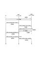
第1に、図4を参照して、本実施形態に係る移動通信システムにおいて、「Bearer Sharing」を開始する際の動作について説明する。 Firstly, with reference to FIG. 4, an operation when starting “Bearer Sharing” in the mobile communication system according to the present embodiment will be described.
図4に示すように、ステップS1001において、マクロセルであるセル#1において「RRC_Connnected状態」にある移動局UEが、無線基地局eNB#1に対して、スモールセルであるセル#2の品質が良くなったことを示す「Measurement report」を送信する。
As shown in FIG. 4, in step S1001, the mobile station UE in the “RRC_Connected state” in the
ステップS1002において、無線基地局eNB#1は、かかる「Measurement report」に応じて、無線基地局eNB#2に対して、「Bearer sharing request」を送信する。
In step S1002, the radio base
ステップS1003において、無線基地局eNB#2は、「Bearer sharing request」に応じて、「Bearer Sharing」を開始することができると判断した場合に、無線基地局eNB#1に対して、「Bearer sharing request ACK」を送信する。
In step S1003, when the radio base
ステップS1004において、無線基地局eNB#1は、移動局UEに対して、EPSベアラ#Bと無線ベアラ#3/#4と無線基地局eNB#1/#2(又は、セル#1/#2)とを関連付けるための情報を含む「RRC connection reconfiguration」を送信する。
In step S1004, the radio base
ステップS1005において、移動局UEは、「RRC connection reconfiguration」に応じて、上述の関連付けを行うと共に、無線基地局eNB#1に対して、「RRC connection reconfiguration complete」を送信する。
In step S1005, the mobile station UE performs the above-described association according to “RRC connection reconfiguration” and transmits “RRC connection reconfiguration complete” to the radio base
無線基地局eNB#1は、ステップS1006において、無線基地局eNB#2に対して、「Bearer sharing complete」を送信すると共に、ステップS1007において、無線基地局eNB#2への移動局UE宛てのデータ(U-planeデータ)の転送を開始する。
In step S1006, the radio base
この結果、ステップS1008において、移動局UEと無線基地局eNB#2との間で、U-planeの経路が疎通することになる、すなわち、「Bearer Sharing」が開始されることになる。
As a result, in step S1008, the U-plane path communicates between the mobile station UE and the radio base
なお、「Bearer Sharing」が開始された場合であっても、C-planeの経路は、移動局UEと無線基地局eNB#1との間のままである。
Even when “Bearer Sharing” is started, the path of the C-plane remains between the mobile station UE and the radio base
第2に、図5を参照して、本実施形態に係る移動通信システムにおいて、「Bearer Sharing」を終了する際の動作(移動局UE及び無線基地局eNB#1主導)について説明する。
2ndly, with reference to FIG. 5, the operation | movement (mobile station UE and radio base
図5に示すように、ステップS2001において、移動局UEと無線基地局eNB#2との間で、U-planeの経路が疎通している状態、すなわち、「Bearer Sharing」が行われている状態で、例えば、セル#2における品質が劣化した場合、ステップS2002において、移動局UEは、無線基地局eNB#1に対して、「Bearer sharing release request」を送信する。
As shown in FIG. 5, in step S2001, the U-plane path is communicated between the mobile station UE and the radio base
ここで、移動局UEは、「Bearer sharing release request」を「Measurement report」に含めて通知してもよい。 Here, the mobile station UE may include “Bearer sharing release request” in the “Measurement report” for notification.
無線基地局eNB#1は、ステップS2003において、無線基地局eNB#2に対して、「Bearer sharing release request」を送信すると共に、無線基地局eNB#2への移動局UE宛てのデータ(U-planeデータ)の転送を終了する。
In step S2003, the radio base
無線基地局eNB#2は、無線基地局eNB#1に対して、ステップS2004において、「Bearer sharing release request ACK」を送信すると共に、ステップS2005において、「Bearer Sharing」の対象であった無線ベアラ#4におけるデータ(U-planeデータ)を全て転送する。
In step S2004, the radio base
ステップS2006において、無線基地局eNB#1は、移動局UEに対して、EPSベアラ#Bと無線ベアラ#3/#4と無線基地局eNB#1/#2(又は、セル#1/#2)との関連付けを解消するための情報を含む「RRC connection reconfiguration」を送信する。
In step S2006, the radio base
ステップS2007において、移動局UEは、「RRC connection reconfiguration」に応じて、上述の関連付けを解消すると共に、無線基地局eNB#1に対して、「RRC connection reconfiguration complete」を送信する。
In step S2007, the mobile station UE cancels the above-described association according to “RRC connection reconfiguration” and transmits “RRC connection reconfiguration complete” to the radio base
無線基地局eNB#1は、ステップS2008において、無線基地局eNB#2に対して、「Bearer sharing release complete」を送信する。
In step S2008, the radio base
第3に、図6を参照して、本実施形態に係る移動通信システムにおいて、「Bearer Sharing」を終了する際の動作(無線基地局eNB#2主導)について説明する。 Thirdly, with reference to FIG. 6, an operation (initiated by the radio base station eNB # 2) when ending “Bearer Sharing” in the mobile communication system according to the present embodiment will be described.
図6に示すように、ステップS3001において、移動局UEと無線基地局eNB#2との間で、U-planeの経路が疎通している状態、すなわち、「Bearer Sharing」が行われている状態で、ステップS3002において、無線基地局eNB#2が、例えば、移動局UEがセル#2外に移動したことを検知した場合、無線基地局eNB#1に対して、「Bearer sharing release request」を送信する。
As shown in FIG. 6, in step S3001, a state in which the U-plane path is communicated between the mobile station UE and the radio base
ステップS3003において、無線基地局eNB#1は、無線基地局eNB#に対して、「Bearer sharing release request ACK」を送信する。
In step S3003, the radio base
ここで、無線基地局eNB#1は、無線基地局eNB#2への移動局UE宛てのデータ(U-planeデータ)の転送を終了する。
Here, the radio base
ステップS3004において、無線基地局eNB#2は、無線基地局eNB#1に対して、「Bearer Sharing」の対象であった無線ベアラ#4におけるデータ(U-planeデータ)を全て転送する。
In step S3004, the radio base
以下、ステップS3005〜S3007の動作は、図5におけるステップS2006〜S2008の動作と同一である。 Hereinafter, the operations in steps S3005 to S3007 are the same as the operations in steps S2006 to S2008 in FIG.
(変更例1)
以下、図7を参照して、本発明の変更例1に係る移動通信システムについて、上述の第1の実施形態に係る移動通信システムとの相違点に着目して説明する。
(Modification 1)
Hereinafter, with reference to FIG. 7, the mobile communication system according to the first modification of the present invention will be described focusing on the differences from the mobile communication system according to the first embodiment described above.
本変更例1に係る移動通信システムでは、上述の第1の実施形態に係る移動通信システムと同様に、1つのEPSベアラの識別子(#B)と複数の無線ベアラの識別子(#3〜#5)と複数の無線基地局eNBの識別子(#1〜#3)とを関連付けている。 In the mobile communication system according to the first modification, as in the mobile communication system according to the first embodiment described above, one EPS bearer identifier (#B) and a plurality of radio bearer identifiers (# 3 to # 5) are used. ) And identifiers (# 1 to # 3) of a plurality of radio base stations eNB.
ここで、本変更例1に係る移動通信システムでは、上述の関連付けは、上りリンクと下りリンクとで異なるように構成されていてもよい。 Here, in the mobile communication system according to the first modification, the above-described association may be configured to be different between the uplink and the downlink.
例えば、図7に示すように、下りリンクにおいて、無線ベアラ#3のデータは、無線基地局eNB#1配下のセル#1を介して、無線基地局eNB#1から移動局UEに送信されるように構成されている。
For example, as shown in FIG. 7, in the downlink, the data of the
また、図7に示すように、下りリンクにおいて、無線ベアラ#4のデータは、無線基地局eNB#2配下のセル#2を介して、無線基地局eNB#2から移動局UEに送信されるように構成されている。
Also, as shown in FIG. 7, in the downlink, the data of the
さらに、図7に示すように、下りリンクにおいて、無線ベアラ#5のデータは、無線基地局eNB#3配下のセル#3を介して、無線基地局eNB#3から移動局UEに送信されるように構成されている。
Further, as shown in FIG. 7, in the downlink, the data of the
一方、上りリンクでは、図7に示すように、無線ベアラ#3〜5のデータの全ては、無線基地局eNB#1配下のセル#1用を介して、移動局UEから無線基地局eNB#1に送信されるように構成されている。
On the other hand, in the uplink, as shown in FIG. 7, all of the data of the
例えば、セル#2/#3が、「DL only Cell」である場合、「DL only Cell」では、上りリンクにおけるデータの送信ができないため、図7に示すように、「UL Cell」が設定されているセル#1において、無線ベアラ#3〜5のデータの全てを送信するようにする必要がある。
For example, when
かかる場合、無線基地局eNB#1は、上りリンクにおいて受信したデータについて、無線基地局間インターフェイスを介して、無線基地局eNB#2/#3のRLCエンティティやPDCPエンティティに転送するように構成されている。
In such a case, the radio base
或いは、RLCエンティティやMACエンティティは、下りリンク及び上りリンクで別々の無線基地局eNBに収容されていてもよい。 Alternatively, the RLC entity and the MAC entity may be accommodated in different radio base stations eNB for the downlink and the uplink.
以上に述べた本実施形態の特徴は、以下のように表現されていてもよい。 The characteristics of the present embodiment described above may be expressed as follows.
本実施形態の第1の特徴は、移動局UEが「Inter-site CA(複数の無線基地局配下のセルを介してキャリアアグリゲーション)」を行うことができるように構成されている移動通信システムであって、複数の無線基地局eNB#1〜#3内のアンカー無線基地局eNB(例えば、無線基地局eNB#1)が、移動局UEとゲートウェイ装置P-GWとの間で設定されている1つのEPSベアラ#Bと、移動局UEと複数の無線基地局eNB#1〜#3との間で設定されている複数の無線ベアラ#3〜#5とを関連付けるように構成されていることを要旨とする。
The first feature of the present embodiment is a mobile communication system configured so that the mobile station UE can perform “Inter-site CA (carrier aggregation via cells under the control of a plurality of radio base stations)”. And the anchor radio base station eNB (for example, radio base station eNB # 1) in several radio base stations eNB # 1- # 3 is set between the mobile station UE and the gateway apparatus P-GW. It is configured to associate one EPS bearer #B with a plurality of
かかる構成によれば、アンカー無線基地局eNBが、1つのEPSベアラと複数の無線ベアラとを関連付けることによって、「Inter-site CA」を行うために適切なベアラ構成を実現することができる。 According to such a configuration, the anchor radio base station eNB can realize an appropriate bearer configuration for performing “Inter-site CA” by associating one EPS bearer with a plurality of radio bearers.
本実施形態の第1の特徴において、アンカー無線基地局eNBは、1つのEPSベアラの識別子(#B)と複数の無線ベアラの各々の識別子(#3〜#5)と複数の無線基地局eNB又はセルの識別子(#1〜#3)とを関連付けるマッピングテーブルを用いて、上述の関連付けを行うように構成されていてもよい。 In the first feature of the present embodiment, the anchor radio base station eNB includes one EPS bearer identifier (#B), each of a plurality of radio bearers (# 3 to # 5), and a plurality of radio base stations eNB. Alternatively, the above association may be performed using a mapping table that associates cell identifiers (# 1 to # 3).
かかる構成によれば、アンカー無線基地局eNBは、マッピングテーブルを用いて、容易に、「Inter-site CA」を行うために適切なベアラ構成を実現することができる。 According to such a configuration, the anchor radio base station eNB can realize an appropriate bearer configuration for easily performing “Inter-site CA” using the mapping table.
本実施形態の第1の特徴において、上述の関連付けは、上りリンクと下りリンクとで異なるように構成されていてもよい。 1st characteristic of this embodiment WHEREIN: The above-mentioned correlation may be comprised so that it may differ with an uplink and a downlink.
かかる構成によれば、スモールセルであるセル#2/#3が「DL only Cell」である場合であっても、「Inter-site CA」を行うことができる。
According to this configuration, even when the
本実施形態の第1の特徴において、個別シグナリングによって、移動局UEに対して、上述の関連付けを行うための情報を通知するように構成されていてもよい。 1st characteristic of this embodiment WHEREIN: You may be comprised so that the information for performing the above-mentioned correlation may be notified with respect to the mobile station UE by separate signaling.
かかる構成によれば、既存のシグナリングを用いて、移動局UEに対して、「Inter-site CA」を行うために適切なベアラ構成を実現するための情報を通知することができる。 According to such a configuration, it is possible to notify the mobile station UE of information for realizing an appropriate bearer configuration for performing “Inter-site CA” using existing signaling.
本実施形態の第1の特徴において、複数の無線基地局eNB#1〜#3及び移動局UEは、無線ベアラの各々に対応するPDCPエンティティを具備しており、PDCPエンティティは、アンカー無線基地局eNB(例えば、無線基地局eNB#1)及び移動局UEに設けられている「Master PDCPエンティティ(マスターPDCPエンティティ)」、及び、アンカー無線基地局eNB(例えば、無線基地局eNB#1)以外の無線基地局eNB#2/#3及び移動局UEに設けられている「Slave PDCPエンティティ(スレーブPDCPエンティティ)を含み、「Master PDCPエンティティ」は、「Slave PDCPエンティティ」を統括するように構成されていてもよい。
In the first feature of the present embodiment, the plurality of radio base
かかる構成によれば、1つのEPSベアラに複数の無線ベアラ#3〜#5が関連付けられている場合に、各無線基地局eNB#1〜#3においてPDCPエンティティが独立して動作するように構成されている場合であっても、上りリンク及び下りリンクにおいて、かかるEPSベアラを介して送受信されるPDCP-PDUに対する順序補正処理を行うことができる。
According to such a configuration, when a plurality of
本実施形態の第2の特徴は、移動局UEが「Inter-site CA」を行うことができるように構成されている移動通信システムにおいて、アンカー無線基地局eNBとして動作することができる無線基地局eNBであって、1つのEPSベアラ#Bと、複数の無線ベアラ#3〜#5とを関連付けるように構成されていることを要旨とする。
A second feature of the present embodiment is that a radio base station that can operate as an anchor radio base station eNB in a mobile communication system configured such that the mobile station UE can perform “Inter-site CA” It is an eNB and is summarized as being configured to associate one EPS bearer #B with a plurality of
本実施形態の第3の特徴は、「Inter-site CA」を行うことができるように構成されている移動局UEであって、1つのEPSベアラ#Bと、複数の無線ベアラ#3〜#5とを関連付けるように構成されていることを要旨とする。
A third feature of the present embodiment is a mobile station UE configured to be able to perform “Inter-site CA”, and includes one EPS bearer #B and a plurality of
なお、上述の移動局UEや無線基地局eNB#1/eNB#2/eNB#3やゲートウェイ装置P-GW/S-GWの動作は、ハードウェアによって実施されてもよいし、プロセッサによって実行されるソフトウェアモジュールによって実施されてもよいし、両者の組み合わせによって実施されてもよい。
The operations of the mobile station UE, the radio base
ソフトウェアモジュールは、RAM(Random Access Memory)や、フラッシュメモリや、ROM(Read Only Memory)や、EPROM(Erasable Programmable ROM)や、EEPROM(Electronically Erasable and Programmable ROM)や、レジスタや、ハードディスクや、リムーバブルディスクや、CD-ROMといった任意形式の記憶媒体内に設けられていてもよい。 The software module includes a RAM (Random Access Memory), a flash memory, a ROM (Read Only Memory), an EPROM (Erasable Programmable ROM), an EEPROM (Electronically Erasable and Programmable ROM, a hard disk, a registerable ROM, a hard disk). Alternatively, it may be provided in a storage medium of an arbitrary format such as a CD-ROM.
かかる記憶媒体は、プロセッサが当該記憶媒体に情報を読み書きできるように、当該プロセッサに接続されている。また、かかる記憶媒体は、プロセッサに集積されていてもよい。また、かかる記憶媒体及びプロセッサは、ASIC内に設けられていてもよい。かかるASICは、移動局UEや無線基地局eNB#1/eNB#2/eNB#3やゲートウェイ装置P-GW/S-GW内に設けられていてもよい。また、かかる記憶媒体及びプロセッサは、ディスクリートコンポーネントとして移動局UEや無線基地局eNB#1/eNB#2/eNB#3やゲートウェイ装置P-GW/S-GW内に設けられていてもよい。
Such a storage medium is connected to the processor so that the processor can read and write information from and to the storage medium. Further, such a storage medium may be integrated in the processor. Such a storage medium and processor may be provided in the ASIC. Such an ASIC may be provided in the mobile station UE, the radio base
以上、上述の実施形態を用いて本発明について詳細に説明したが、当業者にとっては、本発明が本明細書中に説明した実施形態に限定されるものではないということは明らかである。本発明は、特許請求の範囲の記載により定まる本発明の趣旨及び範囲を逸脱することなく修正及び変更態様として実施することができる。従って、本明細書の記載は、例示説明を目的とするものであり、本発明に対して何ら制限的な意味を有するものではない。 Although the present invention has been described in detail using the above-described embodiments, it is obvious to those skilled in the art that the present invention is not limited to the embodiments described in this specification. The present invention can be implemented as modified and changed modes without departing from the spirit and scope of the present invention defined by the description of the scope of claims. Therefore, the description of the present specification is for illustrative purposes and does not have any limiting meaning to the present invention.
eNB#1、eNB#2、eNB#3…無線基地局
UE…移動局
P-GW、S-GW…ゲートウェイ装置
Claims (6)
前記複数の無線基地局内のアンカー無線基地局が、前記移動局とゲートウェイ装置との間で設定されている1つのベアラと、該移動局と前記複数の無線基地局との間で設定されている複数の無線ベアラとを関連付けるように構成されており、
前記アンカー無線基地局は、前記1つのベアラの識別子と前記複数の無線ベアラの各々の識別子と前記複数の無線基地局又はセルの各々の識別子とを関連付けるマッピングテーブルを用いて、前記関連付けを行うように構成されていることを特徴とする移動通信システム。 A mobile communication system configured such that a mobile station can perform carrier aggregation via cells under a plurality of radio base stations,
Anchor radio base stations in the plurality of radio base stations are set between one bearer set between the mobile station and the gateway device, and between the mobile station and the plurality of radio base stations Configured to associate with multiple radio bearers,
The anchor radio base station performs the association using a mapping table that associates the identifier of the one bearer, the identifier of each of the plurality of radio bearers, and the identifier of each of the plurality of radio base stations or cells. The mobile communication system characterized by being comprised in this.
前記PDCPエンティティは、前記アンカー無線基地局及び前記移動局に設けられているマスターPDCPエンティティ、及び、前記アンカー無線基地局以外の前記無線基地局及び該移動局に設けられているスレーブPDCPエンティティを含み、
前記マスターPDCPエンティティは、前記スレーブPDCPエンティティを統括するように構成されていることを特徴とする請求項1乃至3のいずれか一項に記載の移動通信システム。 The plurality of radio base stations and the mobile station each include a PDCP entity corresponding to each of the plurality of radio bearers,
The PDCP entity includes a master PDCP entity provided in the anchor radio base station and the mobile station, and a slave PDCP entity provided in the radio base station other than the anchor radio base station and the mobile station. ,
The mobile communication system according to any one of claims 1 to 3, wherein the master PDCP entity is configured to control the slave PDCP entity.
前記移動局とゲートウェイ装置との間で設定されている1つのベアラと、該移動局と前記複数の無線基地局との間で設定されている複数の無線ベアラとを関連付けるように構成されており、
前記1つのベアラの識別子と前記複数の無線ベアラの各々の識別子と前記複数の無線基地局又はセルの各々の識別子とを関連付けるマッピングテーブルを用いて、前記関連付けを行うように構成されていることを特徴とする無線基地局。 A radio that can operate as an anchor radio base station in a plurality of radio base stations in a mobile communication system configured such that a mobile station can perform carrier aggregation via cells under the plurality of radio base stations. A base station,
One bearer set between the mobile station and the gateway device is configured to associate a plurality of radio bearers set between the mobile station and the plurality of radio base stations. ,
It is configured to perform the association using a mapping table that associates the identifier of the one bearer, the identifiers of the plurality of radio bearers, and the identifiers of the plurality of radio base stations or cells. A featured radio base station.
ゲートウェイ装置との間で設定されている1つのベアラと、前記複数の無線基地局との間で設定されている複数の無線ベアラとを関連付けるように構成されており、
前記1つのベアラの識別子と前記複数の無線ベアラの各々の識別子と前記複数の無線基地局又はセルの各々の識別子とを関連付けるマッピングテーブルを用いて前記複数の無線基地局内のアンカー無線基地局において行われた関連付けに基づいて、前記1つのベアラと、前記複数の無線ベアラとを関連付けるように構成されていることを特徴とする移動局。
A mobile station configured to be able to perform carrier aggregation via cells under a plurality of radio base stations,
It is configured to associate one bearer set with the gateway device and a plurality of radio bearers set with the plurality of radio base stations,
In an anchor radio base station in the plurality of radio base stations using a mapping table that associates an identifier of the one bearer, an identifier of each of the plurality of radio bearers, and an identifier of each of the plurality of radio base stations or cells. A mobile station configured to associate the one bearer with the plurality of radio bearers based on the determined association.
Priority Applications (6)
| Application Number | Priority Date | Filing Date | Title |
|---|---|---|---|
| JP2012187811A JP5871750B2 (en) | 2012-08-28 | 2012-08-28 | Mobile communication system, radio base station and mobile station |
| US14/424,141 US9894639B2 (en) | 2012-08-28 | 2013-08-09 | Mobile communication system, radio base station, and mobile station |
| PCT/JP2013/071643 WO2014034416A1 (en) | 2012-08-28 | 2013-08-09 | Mobile communications system, wireless base station, and mobile station |
| CN201380044911.8A CN104604278B (en) | 2012-08-28 | 2013-08-09 | Mobile communication system, wireless base station and mobile station |
| EP13832977.6A EP2892271B1 (en) | 2012-08-28 | 2013-08-09 | Mobile communications system, wireless base station, and mobile station |
| KR1020157004638A KR20150047494A (en) | 2012-08-28 | 2013-08-09 | Mobile communications system, wireless base station, and mobile station |
Applications Claiming Priority (1)
| Application Number | Priority Date | Filing Date | Title |
|---|---|---|---|
| JP2012187811A JP5871750B2 (en) | 2012-08-28 | 2012-08-28 | Mobile communication system, radio base station and mobile station |
Publications (3)
| Publication Number | Publication Date |
|---|---|
| JP2014045444A JP2014045444A (en) | 2014-03-13 |
| JP2014045444A5 JP2014045444A5 (en) | 2015-10-15 |
| JP5871750B2 true JP5871750B2 (en) | 2016-03-01 |
Family
ID=50183232
Family Applications (1)
| Application Number | Title | Priority Date | Filing Date |
|---|---|---|---|
| JP2012187811A Active JP5871750B2 (en) | 2012-08-28 | 2012-08-28 | Mobile communication system, radio base station and mobile station |
Country Status (6)
| Country | Link |
|---|---|
| US (1) | US9894639B2 (en) |
| EP (1) | EP2892271B1 (en) |
| JP (1) | JP5871750B2 (en) |
| KR (1) | KR20150047494A (en) |
| CN (1) | CN104604278B (en) |
| WO (1) | WO2014034416A1 (en) |
Families Citing this family (8)
| Publication number | Priority date | Publication date | Assignee | Title |
|---|---|---|---|---|
| US10034199B2 (en) * | 2013-03-04 | 2018-07-24 | Samsung Electronics Co., Ltd. | Method and system for parallelizing packet processing in wireless communication |
| JP6231660B2 (en) * | 2014-03-20 | 2017-11-15 | 京セラ株式会社 | Communication control method |
| KR101814248B1 (en) * | 2014-09-05 | 2018-01-04 | 주식회사 케이티 | Methods for transmitting data using a WLAN carrier and Apparatuses thereof |
| CN107071913B (en) | 2014-09-18 | 2020-04-21 | 株式会社Kt | Method and apparatus for processing user plane data |
| CN106717060B (en) | 2014-10-02 | 2020-06-05 | 株式会社Kt | Method for processing data using WLAN carrier and apparatus thereof |
| CN106162931B (en) * | 2015-04-08 | 2020-01-03 | 华为技术有限公司 | Data transmission method and device |
| EP3270622A4 (en) | 2015-04-10 | 2018-03-07 | Kyocera Corporation | User equipment and wireless communication device |
| CN108307450A (en) * | 2016-09-30 | 2018-07-20 | 华为技术有限公司 | A kind of data transmission method, device and system |
Family Cites Families (8)
| Publication number | Priority date | Publication date | Assignee | Title |
|---|---|---|---|---|
| US8498647B2 (en) * | 2008-08-28 | 2013-07-30 | Qualcomm Incorporated | Distributed downlink coordinated multi-point (CoMP) framework |
| US8902805B2 (en) | 2008-10-24 | 2014-12-02 | Qualcomm Incorporated | Cell relay packet routing |
| EP4009733A1 (en) | 2010-02-12 | 2022-06-08 | InterDigital Technology Corporation | Data split between multiple sites |
| US20110310791A1 (en) * | 2010-06-22 | 2011-12-22 | Qualcomm Incorporated | Automatic neighbor relation (anr) functions for relay nodes, home base stations, and related entities |
| US8514756B1 (en) * | 2010-10-15 | 2013-08-20 | Juniper Networks, Inc. | Collectively addressing wireless devices |
| EP2789190B1 (en) | 2011-11-10 | 2021-02-24 | Nokia Technologies Oy | Method and apparatus to route packet flows over two transport radios |
| US9629028B2 (en) * | 2012-03-16 | 2017-04-18 | Qualcomm Incorporated | System and method for heterogeneous carrier aggregation |
| EP2932784B1 (en) * | 2012-12-14 | 2016-12-21 | Telefonaktiebolaget LM Ericsson (publ) | Node apparatus and method for establishing auxiliary bearers |
-
2012
- 2012-08-28 JP JP2012187811A patent/JP5871750B2/en active Active
-
2013
- 2013-08-09 EP EP13832977.6A patent/EP2892271B1/en active Active
- 2013-08-09 CN CN201380044911.8A patent/CN104604278B/en active Active
- 2013-08-09 KR KR1020157004638A patent/KR20150047494A/en not_active Application Discontinuation
- 2013-08-09 WO PCT/JP2013/071643 patent/WO2014034416A1/en active Application Filing
- 2013-08-09 US US14/424,141 patent/US9894639B2/en active Active
Also Published As
| Publication number | Publication date |
|---|---|
| WO2014034416A1 (en) | 2014-03-06 |
| US20150230225A1 (en) | 2015-08-13 |
| EP2892271A4 (en) | 2016-07-13 |
| JP2014045444A (en) | 2014-03-13 |
| CN104604278B (en) | 2018-09-18 |
| KR20150047494A (en) | 2015-05-04 |
| EP2892271B1 (en) | 2018-02-28 |
| US9894639B2 (en) | 2018-02-13 |
| CN104604278A (en) | 2015-05-06 |
| EP2892271A1 (en) | 2015-07-08 |
Similar Documents
| Publication | Publication Date | Title |
|---|---|---|
| JP5871750B2 (en) | Mobile communication system, radio base station and mobile station | |
| US11337062B2 (en) | Security key refresh for dual connectivity | |
| US9839060B2 (en) | Method and apparatus for managing dual connection establishment | |
| CN104584633B (en) | It is operated in radio systems using multiple schedulers | |
| US9467912B2 (en) | Method and apparatus for managing handovers | |
| JP5437422B2 (en) | Radio base station and mobile station | |
| JP6043549B2 (en) | Mobile station | |
| WO2014027604A1 (en) | Mobile communication method and mobile station | |
| WO2014103648A1 (en) | Mobile station and wireless base station | |
| JP5823939B2 (en) | Mobile communication system, radio base station and mobile station | |
| JP6139166B2 (en) | Mobile communication system | |
| US20160029252A1 (en) | Mobile communication method | |
| US20160198467A1 (en) | Mobile station and radio base station | |
| WO2014112545A1 (en) | Mobile communication system | |
| WO2014208711A1 (en) | Mobile communication system and mobile communication method | |
| JP6174343B2 (en) | Network device and mobile station | |
| JP2014068118A (en) | Mobile communication system and radio base station | |
| JP6231286B2 (en) | Mobile station | |
| WO2024064402A1 (en) | Managing a serving cell change in a user equipment | |
| JP6116939B2 (en) | Wireless base station | |
| JP2016001930A (en) | Mobile communication system, radio base station and mobile station | |
| JP2014068119A (en) | Mobile communication method and radio base station |
Legal Events
| Date | Code | Title | Description |
|---|---|---|---|
| A521 | Request for written amendment filed |
Free format text: JAPANESE INTERMEDIATE CODE: A523 Effective date: 20150827 |
|
| A621 | Written request for application examination |
Free format text: JAPANESE INTERMEDIATE CODE: A621 Effective date: 20150827 |
|
| A871 | Explanation of circumstances concerning accelerated examination |
Free format text: JAPANESE INTERMEDIATE CODE: A871 Effective date: 20150827 |
|
| A975 | Report on accelerated examination |
Free format text: JAPANESE INTERMEDIATE CODE: A971005 Effective date: 20150916 |
|
| A131 | Notification of reasons for refusal |
Free format text: JAPANESE INTERMEDIATE CODE: A131 Effective date: 20150929 |
|
| A521 | Request for written amendment filed |
Free format text: JAPANESE INTERMEDIATE CODE: A523 Effective date: 20151124 |
|
| TRDD | Decision of grant or rejection written | ||
| A01 | Written decision to grant a patent or to grant a registration (utility model) |
Free format text: JAPANESE INTERMEDIATE CODE: A01 Effective date: 20151216 |
|
| A61 | First payment of annual fees (during grant procedure) |
Free format text: JAPANESE INTERMEDIATE CODE: A61 Effective date: 20160112 |
|
| R150 | Certificate of patent or registration of utility model |
Ref document number: 5871750 Country of ref document: JP Free format text: JAPANESE INTERMEDIATE CODE: R150 |
|
| R250 | Receipt of annual fees |
Free format text: JAPANESE INTERMEDIATE CODE: R250 |
|
| R250 | Receipt of annual fees |
Free format text: JAPANESE INTERMEDIATE CODE: R250 |
|
| R250 | Receipt of annual fees |
Free format text: JAPANESE INTERMEDIATE CODE: R250 |
|
| R250 | Receipt of annual fees |
Free format text: JAPANESE INTERMEDIATE CODE: R250 |
|
| R250 | Receipt of annual fees |
Free format text: JAPANESE INTERMEDIATE CODE: R250 |
|
| R250 | Receipt of annual fees |
Free format text: JAPANESE INTERMEDIATE CODE: R250 |