JP5871663B2 - Control method of binary power generator - Google Patents
Control method of binary power generator Download PDFInfo
- Publication number
- JP5871663B2 JP5871663B2 JP2012045471A JP2012045471A JP5871663B2 JP 5871663 B2 JP5871663 B2 JP 5871663B2 JP 2012045471 A JP2012045471 A JP 2012045471A JP 2012045471 A JP2012045471 A JP 2012045471A JP 5871663 B2 JP5871663 B2 JP 5871663B2
- Authority
- JP
- Japan
- Prior art keywords
- cooling
- hot water
- heat exchanger
- evaporator
- condenser
- Prior art date
- Legal status (The legal status is an assumption and is not a legal conclusion. Google has not performed a legal analysis and makes no representation as to the accuracy of the status listed.)
- Expired - Fee Related
Links
Images
Landscapes
- Engine Equipment That Uses Special Cycles (AREA)
Description
本発明は、バイナリ発電装置に関する技術であって、特に、このバイナリ発電装置の発電出力を低下させないで暖房または/および給湯の用途等に熱供給することができる技術に関する。 The present invention relates to a technique relating to a binary power generation apparatus, and more particularly to a technique capable of supplying heat to a use of heating or / and hot water supply without lowering the power generation output of the binary power generation apparatus.
近年、地球温暖化対策のため化石燃料の代替エネルギーとして再生可能エネルギーの導入が図られており、太陽光発電システム、風力発電システム、マイクロ水力発電システムが着目されている。さらに、蒸気タービンを回転させるほどの熱量を持たない低温の熱源(たとえば地熱)から低沸点の作動媒体の熱サイクルへ熱を移動し、この循環サイクル内で作動媒体を用いた発電を行うバイナリ発電システムも着目されている。 In recent years, renewable energy has been introduced as a substitute for fossil fuels as a countermeasure against global warming, and solar power generation systems, wind power generation systems, and micro hydropower generation systems have attracted attention. Furthermore, binary power generation that transfers heat from a low-temperature heat source (for example, geothermal heat) that does not have enough heat to rotate the steam turbine to the heat cycle of the low-boiling working medium and generates power using the working medium in this circulation cycle The system is also attracting attention.
このような発電システムにおいて、暖房または/および給湯の用途等に熱供給する技術も開発され、特開2006−292273号公報(特許文献1)は、このような熱電供給システムの一例を開示する。 In such a power generation system, a technique for supplying heat to the use of heating or / and hot water supply or the like has also been developed, and JP 2006-292273 A (Patent Document 1) discloses an example of such a thermoelectric supply system.
ところで、上述したような熱電供給システムにおいて、熱源である温水と作動媒体(冷媒液)との間で熱交換する蒸発器が設けられる。この蒸発器の1次側に温水を供給することにより、2次側の冷媒液が、温水から受けた熱で蒸発され冷媒ガスとなる。冷媒液を蒸発させた温水は蒸発器の1次側出口から排出される。この蒸発器から排出された温水を所望の温度にできると、この温水を暖房または/および給湯等に使用するために供給することができる。 By the way, in the thermoelectric supply system as described above, an evaporator for exchanging heat between hot water as a heat source and a working medium (refrigerant liquid) is provided. By supplying warm water to the primary side of the evaporator, the secondary-side refrigerant liquid is evaporated by the heat received from the warm water to become refrigerant gas. The hot water obtained by evaporating the refrigerant liquid is discharged from the primary side outlet of the evaporator. When the hot water discharged from the evaporator can be brought to a desired temperature, the hot water can be supplied for use in heating or / and hot water supply.
しかしながら、この所望の温度は、顧客により異なる。熱供給のために顧客が要望する温度になるように、蒸発器出口における温水の温度を低めに設定すると、蒸発器内におけるピンチ温度差(1次側の温水と2次側の冷媒液との温度差の最小値)が所望の温度差以下になってしまい、冷媒液を十分に蒸発させることができなくなり、発電出力が低下する可能性がある。このため、従来の熱電供給システムでは、発電出力を低下させないことと、顧客が要望する温度まで温水の温度を低下させることとを、両立させることができない。 However, this desired temperature varies from customer to customer. If the temperature of the hot water at the outlet of the evaporator is set low so that the temperature required by the customer for heat supply is set, the pinch temperature difference in the evaporator (the difference between the hot water on the primary side and the refrigerant liquid on the secondary side) There is a possibility that the minimum value of the temperature difference becomes equal to or less than the desired temperature difference, the refrigerant liquid cannot be sufficiently evaporated, and the power generation output decreases. For this reason, in the conventional thermoelectric supply system, it is impossible to achieve both reduction of the power generation output and reduction of the temperature of the hot water to the temperature desired by the customer.
さらに、斯かる発電装置のみを顧客へ提供する場合、言い換えれば、発電装置がパッケージ化されて製造販売される場合においては、上述のように顧客が要望する温水の温度が異なるため、熱供給のための温水を取り出すようには一般的には設計されていない。このため、発電装置の購入後に、発電出力を低下させないように、所望の温度まで温水の温度を低下させることができたとしても、そのためには、大幅な改造工事が必要となり、実現することは容易ではない。 Furthermore, when only such a power generation device is provided to the customer, in other words, when the power generation device is packaged and manufactured and sold, the temperature of the hot water requested by the customer is different as described above. It is not generally designed to take out hot water for. For this reason, even if the temperature of the hot water can be reduced to the desired temperature so as not to reduce the power generation output after the purchase of the power generation device, a large amount of remodeling work is required for this purpose, It's not easy.
本発明は、上述の問題に鑑みてなされたものであり、発電出力を低下させることなく、かつ、設備導入後であっても大幅に装置を改造する必要なく、バイナリ発電装置における熱源である温水を要望する温度にして供給することができる、バイナリ発電装置の制御方法を提供することを目的とする。 The present invention has been made in view of the above-described problems. Hot water that is a heat source in a binary power generation device without lowering the power generation output and without having to significantly modify the device even after the installation of equipment. it can be supplied in the temperature at which requested that, and an object thereof is to provide a control method of the binary power generation equipment.
上記課題を解決するため、本発明に係るバイナリ発電装置およびその制御方法は、以下の技術的手段を講じている。
即ち、本発明のある局面に係るバイナリ発電装置は、温水を熱源として作動媒体を蒸発させる蒸発器と、前記蒸発器で蒸発した作動媒体の蒸気を膨張させて回転駆動力を発生する膨張機と、前記膨張機で膨張した作動媒体の蒸気を液体に凝縮する凝縮器とを備え、前記回転駆動力を用いて発電機を駆動する。このバイナリ発電装置において、前記蒸発機か
ら排出された温水を冷却する熱交換器へ冷却水を供給および前記熱交換器から冷却水を回収するための接続部を、前記凝縮器の冷却水出口側に設けたことを特徴とする。
In order to solve the above problems, the binary power generation apparatus and the control method thereof according to the present invention employ the following technical means.
That is, a binary power generation apparatus according to an aspect of the present invention includes an evaporator that evaporates a working medium using hot water as a heat source, and an expander that expands the vapor of the working medium evaporated by the evaporator to generate a rotational driving force. A condenser that condenses the vapor of the working medium expanded by the expander into a liquid, and drives the generator using the rotational driving force. In this binary power generator, a connection for supplying cooling water to a heat exchanger that cools the hot water discharged from the evaporator and recovering the cooling water from the heat exchanger is provided on the cooling water outlet side of the condenser. It is characterized by being provided in.
また、このようなバイナリ発電装置において、前記蒸発器から排出された温水を冷却する熱交換器が設けられ、前記凝縮器の冷却水出口側から冷却水を前記熱交換器へ供給するように構成されていることを特徴とする。
また、本発明の別の局面に係る発電装置の制御方法は、上述したバイナリ発電装置を制御するに際し、前記バイナリ発電装置に設けられた蒸発器において、所望のピンチ温度差を維持して排出された温水を、前記バイナリ発電装置に設けられた熱交換器において、所望の温度以下となるように冷却することを特徴とする。
Further, in such a binary power generation apparatus, a heat exchanger for cooling the hot water discharged from the evaporator is provided, and the cooling water is supplied to the heat exchanger from the cooling water outlet side of the condenser. It is characterized by being.
Further, according to another aspect of the present invention, when controlling the above-described binary power generation apparatus, the power generation apparatus control method is performed while maintaining a desired pinch temperature difference in an evaporator provided in the binary power generation apparatus. In the heat exchanger provided in the binary power generator, the hot water is cooled so as to be a desired temperature or less.
好ましくは、前記バイナリ発電装置に、凝縮器の冷却水を冷却する冷却装置を設けておき、前記冷却装置の冷却容量から凝縮器において必要な冷却容量を減算した量よりも少ない分を、前記熱交換器での冷却で用いるように構成することができる。
さらに好ましくは、前記熱交換器の出口における温水の温度を計測して、前記凝縮器からの冷却水の流量を制御することにより、前記蒸発器から排出された温水を冷却するように構成することができる。
なお、本発明にかかるバイナリ発電装置の制御方法の最も好ましい形態としては、温水を熱源として作動媒体を蒸発させる蒸発器と、前記蒸発器で蒸発した作動媒体の蒸気を膨張させて回転駆動力を発生する膨張機と、前記膨張機で膨張した作動媒体の蒸気を液体に凝縮する凝縮器とを備え、前記回転駆動力を用いて発電機を駆動するバイナリ発電装置であって、前記蒸発器から排出された温水を冷却する熱交換器へ冷却水を供給および前記熱交換器から冷却水を回収するための接続部を、前記凝縮器の冷却水出口側に設けたバイナリ発電装置を制御するに際し、前記バイナリ発電装置に設けられた蒸発器において、所望のピンチ温度差を維持して排出された温水を、前記バイナリ発電装置に設けられた熱交換器において、所望の温度以下となるように冷却し系外の利用先へ供給すると共に、前記熱交換器の出口における温水の温度を計測して、前記凝縮器からの冷却水の流量を制御することにより、前記蒸発器から排出された温水を冷却することを特徴とする。
また、本発明にかかるバイナリ発電装置の制御方法の最も好ましい別の形態としては、温水を熱源として作動媒体を蒸発させる蒸発器と、前記蒸発器で蒸発した作動媒体の蒸気を膨張させて回転駆動力を発生する膨張機と、前記膨張機で膨張した作動媒体の蒸気を液体に凝縮する凝縮器とを備え、前記回転駆動力を用いて発電機を駆動するバイナリ発電装置であって、前記蒸発器から排出された温水を冷却する熱交換器が設けられ、前記凝縮器の冷却水出口側から冷却水を前記熱交換器へ供給するように構成されているバイナリ発電装置を制御するに際し、前記バイナリ発電装置に設けられた蒸発器において、所望のピンチ温度差を維持して排出された温水を、前記バイナリ発電装置に設けられた熱交換器において、所望の温度以下となるように冷却し系外の利用先へ供給すると共に、前記熱交換器の出口における温水の温度を計測して、前記凝縮器からの冷却水の流量を制御することにより、前記蒸発器から排出された温水を冷却することを特徴とする。
Preferably, the binary power generation device is provided with a cooling device for cooling the cooling water of the condenser, and an amount smaller than the amount obtained by subtracting the cooling capacity necessary for the condenser from the cooling capacity of the cooling device is reduced to the heat capacity. It can be configured to be used for cooling in an exchanger.
More preferably, the hot water discharged from the evaporator is cooled by measuring the temperature of the hot water at the outlet of the heat exchanger and controlling the flow rate of the cooling water from the condenser. Can do.
The most preferable mode of the control method of the binary power generator according to the present invention is an evaporator that evaporates the working medium using hot water as a heat source, and the rotational driving force is increased by expanding the vapor of the working medium evaporated by the evaporator. A binary power generator that drives the generator using the rotational driving force, comprising: an expander that is generated; and a condenser that condenses the vapor of the working medium expanded in the expander into a liquid. When controlling the binary power generator provided on the cooling water outlet side of the condenser with a connection for supplying the cooling water to the heat exchanger for cooling the discharged hot water and recovering the cooling water from the heat exchanger. In the evaporator provided in the binary power generation device, the hot water discharged while maintaining a desired pinch temperature difference is reduced to a desired temperature or less in the heat exchanger provided in the binary power generation device. And is discharged from the evaporator by measuring the temperature of the hot water at the outlet of the heat exchanger and controlling the flow rate of the cooling water from the condenser. The heated water is cooled.
Further, as the most preferable another form of the control method of the binary power generation device according to the present invention, an evaporator that evaporates the working medium using hot water as a heat source, and rotation of the working medium evaporated by the evaporator is expanded and driven. A binary power generation apparatus that includes an expander that generates force and a condenser that condenses the vapor of the working medium expanded in the expander into a liquid, and that drives the generator using the rotational driving force. A heat exchanger for cooling the hot water discharged from the condenser is provided, and when controlling a binary power generator configured to supply cooling water to the heat exchanger from the cooling water outlet side of the condenser, In the evaporator provided in the binary power generation device, the hot water discharged while maintaining the desired pinch temperature difference becomes equal to or lower than the desired temperature in the heat exchanger provided in the binary power generation device. The temperature of the hot water at the outlet of the heat exchanger is measured and the flow rate of the cooling water from the condenser is controlled, and then discharged from the evaporator. The hot water is cooled.
本発明に係るバイナリ発電装置の制御方法を用いることにより、発電出力を低下させることなく、かつ、設備導入後であっても大幅に装置を改造する必要なく、バイナリ発電装置における熱源である温水を要望する温度にして供給することができる。 By using the control method of the binary power generation equipment according to the present invention, without lowering the power generation output, and even after introducing equipment without the need to modify significantly device, which is a heat source in a binary power generator hot water Can be supplied at a desired temperature.
<第1実施形態>
以下、本発明の第1実施形態に係るバイナリ発電装置100およびその制御方法を、図面に基づき詳しく説明する。なお、以下の説明では、異なる実施形態であっても同一の部品には同一の符号を付してある。それらの名称及び機能も同じである。したがって、それらについての詳細な説明は繰り返さない。
<First Embodiment>
Hereinafter, a
[全体構成]
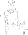
図1に示すように、本実施形態に係るバイナリ発電装置100は、膨張機30で発生した回転駆動力を用いて発電機40を駆動することにより発電を行うものである。なお、以下においては、蒸発器10の熱源として用いる加熱媒体を温水として、凝縮器60の冷媒として用いる冷却媒体を水として説明する。
[overall structure]
As shown in FIG. 1, the binary
図1に示すように、バイナリ発電装置100は、液体の冷媒(冷媒液)を蒸発させる蒸発器10と、この蒸発器10で蒸発した冷媒ガスを過熱(スーパーヒート)状態に加熱する過熱器20と、冷媒ガスの蒸気を膨張させて回転駆動力を発生する膨張機30と、膨張機30で膨張させられた冷媒ガスを液体に凝縮する凝縮器60と、この凝縮器60で凝縮させられた冷媒液を循環させる冷媒ポンプ70とを、閉ループ状の循環配管上に備えている。冷媒ポンプ70は、冷媒液を蒸発器10へ向けて圧送する。
As shown in FIG. 1, a binary
本実施形態に係るバイナリ発電装置100は、このような機器から構成される従来のバイナリ発電装置に加えて、蒸発器10の温水出口に温水出口温度調整熱交換器50(以下、出口熱交換器50と記載)を設け、その出口熱交換器50の2次側に、凝縮器60の2次側から排出された冷却水を供給するようにしたことを特徴とする。
蒸発器10および過熱器20は、いずれも熱源である温水と冷媒液との間で熱交換する機器であって、蒸発器10および過熱器20の1次側に温水を供給することにより、2次側の冷媒液が温水から受けた熱で蒸発し、さらに過熱状態まで加熱されるようになっている。本実施形態においては蒸発器10と過熱器20とを別体の機器として記載しているが、一体の熱交換器であってもよく、さらに、過熱器20を備えない構成であっても、予熱
器を備える構成であっても構わない。
The binary
Each of the
膨張機30は、冷媒ガスを膨張させることにより回転駆動する駆動部を有している。本実施形態における膨張機は、スクリュ型であっても、ラジアル型であっても、スクロール型であっても構わない。スクリュ型膨張機である場合には、駆動部としてスクリュロータを有している。このスクリュロータで発生した回転駆動力は発電機40へ伝えられ、発電機40で発電が行われる。
The
凝縮器60は、水と冷媒ガスとの間で熱交換する機器であって、凝縮器60の2次側に水を供給することで1次側の冷媒ガスを凝縮できるようになっている。凝縮器60の2次側の冷却水は、冷却水ポンプ64により冷却塔62(および後述する出口熱交換器50)との間で循環されて、凝縮器60において冷媒ガスを凝縮して冷媒液へ、気相から液層へ相転移させる。
The
出口熱交換器50の2次側の冷却水は、凝縮器60の2次側の冷却水が使用される。より詳しくは、凝縮器60の2次側の冷却水出口と出口熱交換器50の2次側の冷却水入口とが制御バルブ52を介して接続され、出口熱交換器50の2次側の冷却水出口と冷却塔62の入口とが接続されている。すなわち、蒸発器10から排出された温水を冷却する出口熱交換器50が設けられ、凝縮器60の冷却水出口側から冷却水を出口熱交換器50へ供給し、出口熱交換器50で温水を冷却した冷却水を冷却塔62へ回収するように構成されている。
As the cooling water on the secondary side of the
このように、本実施形態に係るバイナリ発電装置100は、蒸発器10における1次側から排出された温水を冷却する熱交換器として、出口熱交換器50を備える。出口熱交換器50は、温水を冷却し、顧客の要望する温度まで低下させる。この場合において、出口熱交換器50出口における温水の温度が温度計54により計測されて、この計測結果に基づいて、温水を冷却する冷却水の流量を制御バルブ52で調整することにより、出口熱交換器50出口における温水の温度が所望の温度まで冷却される。
As described above, the binary
このとき、蒸発器10において、所望のピンチ温度差(1次側の温水と2次側の冷媒液との温度差の最小値)を維持して排出された温水が出口熱交換器50において、所望の温度以下となるように冷却される。このため、蒸発器10(および過熱器20)では、ピンチ温度差が所望の温度差以上を確保でき、冷媒液を十分に蒸発させることができるので、発電出力が低下することがない。さらに、この出口熱交換器50の2次側に供給される冷却水は凝縮器60の冷却水を流用しているので以下の制限を有する。
At this time, the warm water discharged in the
冷却塔62(冷却装置)の冷却容量から凝縮器60において必要な冷却容量を減算した量よりも少ない分が、出口熱交換器50での冷却で用いられる。このため、凝縮器60では、冷媒ガスを所望の圧力および所望の温度の冷媒液に凝縮できるので、発電出力が低下することがない。これらの制御方法の詳細については後述する。
上述したバイナリ発電装置100で発電を行う際には、温水ポンプを用いて温水を蒸発器10および過熱器20の1次側に送る。蒸発器10および過熱器20の2次側に供給される冷媒液は(水より)低沸点の有機媒体であるため、容易に蒸発して、冷媒液から過熱状態の冷媒ガスへ変化する。冷媒液を過熱状態の冷媒ガスへ変化させた温水は、出口熱交換器50で冷却される。
A portion smaller than the amount obtained by subtracting the cooling capacity necessary for the
When generating power with the binary
このようにして得られた冷媒ガスは膨張機30に送られ、膨張機30内で膨張してスクリュロータ(駆動部)を回転させ、ロータの回転軸が発電機40の回転軸が回転されて、発電機40で発電される。
このようにしてスクリュロータを回転させるのに用いられた冷媒ガスは、凝縮器60に送られる。凝縮器60の2次側には冷却水ポンプ64を用いて冷却水が冷却塔62との間で循環されており、凝縮器60での熱交換により1次側の冷媒ガスが凝縮されて冷媒液に戻る。このようにして凝縮器60で液体になった冷媒液は、冷媒ポンプ70を用いて再び蒸発器10および過熱器20へ送られ蒸発に用いられる。このような冷媒(冷媒液および冷媒ガス)が循環するサイクル(バイナリサイクル)においては、膨張機30で冷媒ガスが膨張し、膨張する冷媒ガスによりスクリュロータが回転して回転駆動力が生じる。
The refrigerant gas obtained in this way is sent to the
The refrigerant gas used for rotating the screw rotor in this way is sent to the
[制御方法]
上述したように、蒸発器10出口における温水の温度が温度計54により計測される。この計測結果に基づいて出口熱交換器50の温水出口温度が所望の温度になるように、出口熱交換器50へ供給される流量を制御バルブ52により調整する。
この場合においても、以下の制限を超えては、出口熱交換器50へ冷却水が供給されることはない。冷却塔62(冷却装置)の冷却容量Q(1)から凝縮器60において必要な冷却容量Q(2)を減算した量Q(3)よりも少ない分しか、出口熱交換器50での冷却に用いられない。なお、通常は、Q(3)>0となるように、Q(1)は余裕を持って設計されている。
[Control method]
As described above, the temperature of the hot water at the outlet of the
Even in this case, the cooling water is not supplied to the
すなわち、Q(3)>0を維持している限り、温度計54により計測された結果に基づいて、出口熱交換器50の温水出口温度が所望の温度になるように、冷却水の流量が制御バルブ52で調整される。
出口熱交換器50の温水入口温度(蒸発器10の温水出口温度)が高く、または/および、顧客の要望する所望の温水温度が低い場合には、出口熱交換器50において必要な冷却容量Q(4)がQ(3)を超える場合がある。この場合には、温水を所望の温度まで低下させることよりも、凝縮器60において必要な冷却容量Q(2)が確保すること(発電出力が低下しないこと)を優先させる。このため、出口熱交換器50へ供給される冷却水の流量が制御バルブ52により制限される(インターロックがかかる)。
That is, as long as Q (3)> 0 is maintained, the flow rate of the cooling water is set so that the hot water outlet temperature of the
When the hot water inlet temperature of the outlet heat exchanger 50 (hot water outlet temperature of the evaporator 10) is high and / or the desired hot water temperature desired by the customer is low, the cooling capacity Q required in the outlet heat exchanger 50 (4) may exceed Q (3). In this case, priority is given to securing the necessary cooling capacity Q (2) in the condenser 60 (not reducing the power generation output) rather than lowering the hot water to a desired temperature. For this reason, the flow rate of the cooling water supplied to the
なお、上述したQ(1)〜Q(4)の算出方法は、特に制限されるものはなく、本実施形態に係るバイナリ発電装置の効果が発現できる方法であれば構わない。
このようにして、本実施形態に係るバイナリ発電装置100によると、暖房または/および給湯に利用するための、顧客が要望する温度の温水を得ることができるともに、発電電力を低下させることもない。
In addition, the calculation method of Q (1) -Q (4) mentioned above does not have a restriction | limiting in particular, What is necessary is just a method which can express the effect of the binary power generator concerning this embodiment.
As described above, according to the binary
<第2実施形態>
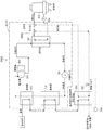
以下、本発明の第2実施形態に係るバイナリ発電装置200について説明する。なお、同一の符号を付した同一の部品についての説明は繰り返さない。さらに、制御方法は、上述の第1実施形態と同じであるため、制御方法についての説明は繰り返さない。
図2に示すように、本実施形態に係るバイナリ発電装置200は、パッケージ部分210とそれ以外の部分(冷却塔62、冷却水ポンプ64、出口熱交換器50、制御バルブ52、温度計54)とで構成される。パッケージ部分210は、バイナリ発電装置200の製造販売会社により、製造されて販売される部分である。なお、このパッケージ部分210に含まれる部品は、限定的に考えられるべきではなく、バイナリ発電装置の基本的な部品と後述する接続部(三方弁、開閉バルブ)とを含むものであれば構わない。たとえば、冷却水ポンプ64はパッケージ部分210に含まれても構わない。
Second Embodiment
Hereinafter, a binary
As shown in FIG. 2, the binary
本実施形態に係るバイナリ発電装置200は、パッケージ部分210に、三方弁262および三方弁264を備えることを特徴とする。これらの三方弁262および三方弁264は、凝縮器60の冷却水出口と冷却塔62との間に設けられる。より詳しくは、これらの三方弁262および三方弁264は、凝縮器60の冷却水出口と冷却塔62に接続される接続バルブ(図示しない)との間に直列に設けられる。
The binary
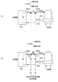
顧客が出口熱交換器50を使用しない場合には、これらの三方弁262および三方弁264は、図3(A)に示すように用いられ、顧客が出口熱交換器50を使用する場合には、これらの三方弁262および三方弁264は、図3(B)に示すように用いられる。
図3(A)に示す状態においては、(1)三方弁262の凝縮器60側および冷却塔62側が開状態、かつ、出口熱交換器50側が閉状態で、(2)三方弁264の凝縮器60側および冷却塔62側が開状態、かつ、出口熱交換器50側が閉状態で、三方弁262と三方弁264とが直接連通している。このため、冷却水ポンプ64により、冷却水は、凝縮器60と冷却塔62との間で循環される。
When the customer does not use the
In the state shown in FIG. 3A, (1) the
一方、図3(B)に示す状態においては、(1)三方弁262の凝縮器60側および出口熱交換器50側が開状態、かつ、冷却塔62側が閉状態で、(2)三方弁264の冷却塔62側および出口熱交換器50側が開状態、かつ、凝縮器60側が閉状態で、三方弁262と三方弁264とが出口熱交換器50を介して連通している。このため、冷却水ポン
プ64により、冷却水は、凝縮器60および出口熱交換器50と冷却塔62との間で循環される。このとき、上述したように、蒸発器10において、所望のピンチ温度差を維持して排出された温水が出口熱交換器50において、所望の温度以下となるように冷却される。さらに、冷却塔62(冷却装置)の冷却容量から凝縮器60において必要な冷却容量を減算した量よりも少ない分が、出口熱交換器50での冷却で用いられる。
On the other hand, in the state shown in FIG. 3B, (1) the three-
なお、図3(A)に示す凝縮器60の冷却水の状態と、図3(B)に示す凝縮器60および出口熱交換器50の冷却水の状態とを実現できるものであれば、接続部は2つの三方弁に限定されるものではない。すなわち、凝縮器60の冷却水出口側に、蒸発器10から排出された温水を冷却する出口熱交換器50へ冷却水を供給、および、出口熱交換器50から冷却水を回収するための接続部が、パッケージ210内に設けられていればよい。
If the state of the cooling water of the
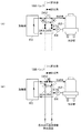
たとえば、図4に示すように、接続部として3つの開閉バルブを設けても構わない。開閉バルブ362は凝縮器60と冷却塔62との間に設けられ、この開閉バルブ362の前(凝縮器60側)には供給配管374との分岐部が設けられ、この開閉バルブ362の後(冷却塔62側)には回収配管376との合流部が設けられる。開閉バルブ364は供給配管374に、開閉バルブ366は回収配管376に、それぞれに設けられる。
For example, as shown in FIG. 4, three open / close valves may be provided as connecting portions. The opening /
図4(A)に示す状態においては、開閉バルブ362が開状態、かつ、開閉バルブ364および開閉バルブ366が閉状態で、冷却水ポンプ64により、冷却水は、凝縮器60と冷却塔62との間で循環される。
一方、図4(B)に示す状態においては、開閉バルブ362が閉状態、かつ、開閉バルブ364および開閉バルブ366が開状態で、冷却水ポンプ64により、冷却水は、凝縮器60および出口熱交換器50と冷却塔62との間で循環される。
In the state shown in FIG. 4A, the opening /
On the other hand, in the state shown in FIG. 4B, the opening /
このようにして、本実施形態に係るバイナリ発電装置200によると、設備導入後であっても大幅に装置を改造する必要なく、暖房または/および給湯に利用するための、顧客が要望する温度の温水を得ることができるともに、発電電力を低下させることもない。
なお、今回開示された実施形態はすべての点で例示であって制限的なものではないと考えられるべきである。本発明の範囲は上記した説明ではなくて特許請求の範囲によって示され、特許請求の範囲と均等の意味および範囲内でのすべての変更が含まれることが意図される。
In this way, according to the binary
The embodiment disclosed this time should be considered as illustrative in all points and not restrictive. The scope of the present invention is defined by the terms of the claims, rather than the description above, and is intended to include any modifications within the scope and meaning equivalent to the terms of the claims.
また、今回開示された実施形態において、明示的に開示されていない事項、例えば、運転条件や操業条件、各種パラメータ、構成物の寸法、重量、体積などは、当業者が通常実施する範囲を逸脱するものではなく、通常の当業者であれば、容易に想定することが可能な値を採用している。 Further, in the embodiment disclosed this time, matters that are not explicitly disclosed, for example, operating conditions and operating conditions, various parameters, dimensions, weights, volumes, and the like of a component deviate from a range that a person skilled in the art normally performs. Instead, values that can be easily assumed by those skilled in the art are employed.
10 蒸発器
20 過熱器
30 膨張機
40 発電機
50 温水出口温度調整熱交換器(出口熱交換器)
60 凝縮器
70 冷媒ポンプ
100 バイナリ発電装置
262、264 三方弁
362、364、366 開閉バルブ
374 供給配管
376 回収配管
DESCRIPTION OF
60 Condenser 70
Claims (3)
前記バイナリ発電装置に設けられた蒸発器において、所望のピンチ温度差を維持して排出された温水を、前記バイナリ発電装置に設けられた熱交換器において、所望の温度以下となるように冷却し系外の利用先へ供給すると共に、前記熱交換器の出口における温水の温度を計測して、前記凝縮器からの冷却水の流量を制御することにより、前記蒸発器から排出された温水を冷却する
ことを特徴とするバイナリ発電装置の制御方法。 An evaporator that evaporates the working medium using hot water as a heat source, an expander that expands the vapor of the working medium evaporated by the evaporator to generate a rotational driving force, and the vapor of the working medium expanded by the expander into liquid and a condenser for condensing, a binary power generator that drives a generator using the rotation driving force, the supply and the heat exchanger cooling water to the heat exchanger for cooling the hot water discharged from the evaporator a connection portion for recovering the cooling water from the vessel, when controlling the binary power generation device provided in the cooling water outlet side of the condenser,
In the evaporator provided in the binary power generation device, the hot water discharged while maintaining a desired pinch temperature difference is cooled in the heat exchanger provided in the binary power generation device so that the temperature is lower than the desired temperature. The hot water discharged from the evaporator is cooled by supplying it to a user outside the system and measuring the temperature of the hot water at the outlet of the heat exchanger and controlling the flow rate of the cooling water from the condenser. Do
A control method for a binary power generation apparatus.
前記バイナリ発電装置に設けられた蒸発器において、所望のピンチ温度差を維持して排出された温水を、前記バイナリ発電装置に設けられた熱交換器において、所望の温度以下となるように冷却し系外の利用先へ供給すると共に、前記熱交換器の出口における温水の温度を計測して、前記凝縮器からの冷却水の流量を制御することにより、前記蒸発器から排出された温水を冷却する
ことを特徴とするバイナリ発電装置の制御方法。 An evaporator that evaporates the working medium using hot water as a heat source, an expander that expands the vapor of the working medium evaporated by the evaporator to generate a rotational driving force, and the vapor of the working medium expanded by the expander into liquid and a condenser for condensing said a binary power generator that drives a generator using a rotary driving force, said heat exchanger is provided for cooling the discharged hot water from the evaporator, the cooling of the condenser upon controlling the structure which do resolver Inari power generator to supply to said heat exchanger cooling water from the water outlet,
In the evaporator provided in the binary power generation device, the hot water discharged while maintaining a desired pinch temperature difference is cooled in the heat exchanger provided in the binary power generation device so that the temperature is lower than the desired temperature. The hot water discharged from the evaporator is cooled by supplying it to a user outside the system and measuring the temperature of the hot water at the outlet of the heat exchanger and controlling the flow rate of the cooling water from the condenser. Do
A control method for a binary power generation apparatus.
前記冷却装置の冷却容量から凝縮器において必要な冷却容量を減算した量よりも少ない分を、前記熱交換器での冷却で用いるようにすることを特徴とする請求項1又は2に記載のバイナリ発電装置の制御方法。 A cooling device for cooling the cooling water of the condenser is provided in the binary power generator,
3. The binary according to claim 1, wherein an amount smaller than an amount obtained by subtracting a cooling capacity necessary for a condenser from a cooling capacity of the cooling device is used for cooling in the heat exchanger. 4. A method for controlling a power generator.
Priority Applications (1)
| Application Number | Priority Date | Filing Date | Title |
|---|---|---|---|
| JP2012045471A JP5871663B2 (en) | 2012-03-01 | 2012-03-01 | Control method of binary power generator |
Applications Claiming Priority (1)
| Application Number | Priority Date | Filing Date | Title |
|---|---|---|---|
| JP2012045471A JP5871663B2 (en) | 2012-03-01 | 2012-03-01 | Control method of binary power generator |
Publications (2)
| Publication Number | Publication Date |
|---|---|
| JP2013181456A JP2013181456A (en) | 2013-09-12 |
| JP5871663B2 true JP5871663B2 (en) | 2016-03-01 |
Family
ID=49272303
Family Applications (1)
| Application Number | Title | Priority Date | Filing Date |
|---|---|---|---|
| JP2012045471A Expired - Fee Related JP5871663B2 (en) | 2012-03-01 | 2012-03-01 | Control method of binary power generator |
Country Status (1)
| Country | Link |
|---|---|
| JP (1) | JP5871663B2 (en) |
Families Citing this family (5)
| Publication number | Priority date | Publication date | Assignee | Title |
|---|---|---|---|---|
| JP2014084857A (en) * | 2012-10-28 | 2014-05-12 | Yasuharu Kawabata | Binary power generation system |
| JP6198673B2 (en) * | 2014-05-15 | 2017-09-20 | 株式会社神戸製鋼所 | Thermal energy recovery device and control method |
| JP6394862B2 (en) * | 2014-07-02 | 2018-09-26 | 株式会社Ihi回転機械エンジニアリング | Waste heat power generator |
| JP6581396B2 (en) * | 2015-06-11 | 2019-09-25 | 株式会社Ihi回転機械エンジニアリング | Binary power generation system and binary power generation method |
| JP6335859B2 (en) * | 2015-09-29 | 2018-05-30 | 株式会社神戸製鋼所 | Thermal energy recovery system |
Family Cites Families (5)
| Publication number | Priority date | Publication date | Assignee | Title |
|---|---|---|---|---|
| JPS52133446A (en) * | 1976-05-01 | 1977-11-08 | Nippon Steel Corp | Hot water transporting system |
| JPS5791385A (en) * | 1980-11-27 | 1982-06-07 | Toshiba Corp | Binary cycle plant of terrestrial heat |
| JPS5968505A (en) * | 1982-10-14 | 1984-04-18 | Toshiba Corp | Low boiling point medium cycle plant |
| JPH0631519B2 (en) * | 1985-11-09 | 1994-04-27 | 株式会社笹倉機械製作所 | Dual-purpose treatment method for geothermal water |
| JPH0784852B2 (en) * | 1986-03-06 | 1995-09-13 | 株式会社明電舍 | Cogeneration system |
-
2012
- 2012-03-01 JP JP2012045471A patent/JP5871663B2/en not_active Expired - Fee Related
Also Published As
| Publication number | Publication date |
|---|---|
| JP2013181456A (en) | 2013-09-12 |
Similar Documents
| Publication | Publication Date | Title |
|---|---|---|
| JP6132214B2 (en) | Rankine cycle apparatus, combined heat and power system, and operation method of Rankine cycle apparatus | |
| JP5462979B2 (en) | Control of thermal cycle process | |
| JP5871663B2 (en) | Control method of binary power generator | |
| JP5596631B2 (en) | Binary power generator | |
| WO2012003021A1 (en) | Power generator using a wind turbine, a hydrodynamic retarder, and an organic rankine cycle drive | |
| WO2011068880A2 (en) | Utilizing steam and/or hot water generated using solar energy | |
| JP5596606B2 (en) | Power generator | |
| BR112014030826B1 (en) | SOLAR ENERGY SYSTEM; AND THERMAL ENERGY TRANSFER METHOD BETWEEN A REGION AND A SOLAR ENERGY SYSTEM | |
| BR112014030970B1 (en) | SOLAR ENERGY SYSTEM | |
| JP2016121665A (en) | Thermal power generation device | |
| JP6583617B2 (en) | Evaporator, Rankine cycle device and cogeneration system | |
| JP6021526B2 (en) | COOLING WATER SUPPLY SYSTEM AND BINARY POWER GENERATOR HAVING THE SAME | |
| JP5592305B2 (en) | Power generator | |
| JP4684762B2 (en) | Power generator | |
| JP2015096703A (en) | Heat recovery power generation system | |
| JP5910122B2 (en) | Heat recovery generator | |
| JP2010190460A (en) | Air conditioning system | |
| JP5924980B2 (en) | Binary power generator and control method thereof | |
| JP6433749B2 (en) | Thermal energy recovery device | |
| WO2013121270A1 (en) | Apparatus and method for increasing power plant efficiency at partial loads | |
| KR101481010B1 (en) | Ocean thermal energy conversion system and operation method thereof | |
| JP6060029B2 (en) | Rotating machine drive system | |
| EP3112622B1 (en) | Binary power generation system and binary power generation method | |
| KR101315918B1 (en) | Organic rankine cycle for using low temperature waste heat and absorbtion type refrigerator | |
| US10677101B2 (en) | Combined heat and power system and operating method of combined heat and power system |
Legal Events
| Date | Code | Title | Description |
|---|---|---|---|
| A621 | Written request for application examination |
Free format text: JAPANESE INTERMEDIATE CODE: A621 Effective date: 20140901 |
|
| A131 | Notification of reasons for refusal |
Free format text: JAPANESE INTERMEDIATE CODE: A131 Effective date: 20150526 |
|
| A977 | Report on retrieval |
Free format text: JAPANESE INTERMEDIATE CODE: A971007 Effective date: 20150528 |
|
| A521 | Request for written amendment filed |
Free format text: JAPANESE INTERMEDIATE CODE: A523 Effective date: 20150714 |
|
| TRDD | Decision of grant or rejection written | ||
| A01 | Written decision to grant a patent or to grant a registration (utility model) |
Free format text: JAPANESE INTERMEDIATE CODE: A01 Effective date: 20160112 |
|
| A61 | First payment of annual fees (during grant procedure) |
Free format text: JAPANESE INTERMEDIATE CODE: A61 Effective date: 20160112 |
|
| R150 | Certificate of patent or registration of utility model |
Ref document number: 5871663 Country of ref document: JP Free format text: JAPANESE INTERMEDIATE CODE: R150 |
|
| LAPS | Cancellation because of no payment of annual fees |