JP5869925B2 - Myocardial excitation waveform detection device and detection program - Google Patents
Myocardial excitation waveform detection device and detection program Download PDFInfo
- Publication number
- JP5869925B2 JP5869925B2 JP2012058748A JP2012058748A JP5869925B2 JP 5869925 B2 JP5869925 B2 JP 5869925B2 JP 2012058748 A JP2012058748 A JP 2012058748A JP 2012058748 A JP2012058748 A JP 2012058748A JP 5869925 B2 JP5869925 B2 JP 5869925B2
- Authority
- JP
- Japan
- Prior art keywords
- waveform
- myocardial
- detection
- period
- excitation
- Prior art date
- Legal status (The legal status is an assumption and is not a legal conclusion. Google has not performed a legal analysis and makes no representation as to the accuracy of the status listed.)
- Active
Links
- 230000002107 myocardial effect Effects 0.000 title claims description 178
- 230000005284 excitation Effects 0.000 title claims description 174
- 238000001514 detection method Methods 0.000 title claims description 146
- 230000007717 exclusion Effects 0.000 claims description 48
- 238000004458 analytical method Methods 0.000 claims description 33
- 238000000034 method Methods 0.000 claims description 29
- 206010003658 Atrial Fibrillation Diseases 0.000 claims description 14
- 238000004364 calculation method Methods 0.000 claims description 11
- 230000000747 cardiac effect Effects 0.000 claims description 6
- 210000004165 myocardium Anatomy 0.000 claims description 3
- 230000000694 effects Effects 0.000 description 5
- 238000010586 diagram Methods 0.000 description 3
- 210000002837 heart atrium Anatomy 0.000 description 3
- 238000004422 calculation algorithm Methods 0.000 description 2
- 238000013153 catheter ablation Methods 0.000 description 2
- 206010001497 Agitation Diseases 0.000 description 1
- 206010049447 Tachyarrhythmia Diseases 0.000 description 1
- 208000001871 Tachycardia Diseases 0.000 description 1
- 230000001746 atrial effect Effects 0.000 description 1
- 230000002526 effect on cardiovascular system Effects 0.000 description 1
- 230000007831 electrophysiology Effects 0.000 description 1
- 238000002001 electrophysiology Methods 0.000 description 1
- 210000005259 peripheral blood Anatomy 0.000 description 1
- 239000011886 peripheral blood Substances 0.000 description 1
- 238000001050 pharmacotherapy Methods 0.000 description 1
- 238000011002 quantification Methods 0.000 description 1
- 238000002636 symptomatic treatment Methods 0.000 description 1
Images


Classifications
-
- A—HUMAN NECESSITIES
- A61—MEDICAL OR VETERINARY SCIENCE; HYGIENE
- A61B—DIAGNOSIS; SURGERY; IDENTIFICATION
- A61B5/00—Measuring for diagnostic purposes; Identification of persons
- A61B5/24—Detecting, measuring or recording bioelectric or biomagnetic signals of the body or parts thereof
- A61B5/316—Modalities, i.e. specific diagnostic methods
- A61B5/318—Heart-related electrical modalities, e.g. electrocardiography [ECG]
- A61B5/346—Analysis of electrocardiograms
- A61B5/349—Detecting specific parameters of the electrocardiograph cycle
- A61B5/361—Detecting fibrillation
-
- A—HUMAN NECESSITIES
- A61—MEDICAL OR VETERINARY SCIENCE; HYGIENE
- A61B—DIAGNOSIS; SURGERY; IDENTIFICATION
- A61B5/00—Measuring for diagnostic purposes; Identification of persons
- A61B5/72—Signal processing specially adapted for physiological signals or for diagnostic purposes
- A61B5/7235—Details of waveform analysis
Landscapes
- Health & Medical Sciences (AREA)
- Life Sciences & Earth Sciences (AREA)
- Engineering & Computer Science (AREA)
- Cardiology (AREA)
- Molecular Biology (AREA)
- General Health & Medical Sciences (AREA)
- Biophysics (AREA)
- Biomedical Technology (AREA)
- Heart & Thoracic Surgery (AREA)
- Medical Informatics (AREA)
- Physics & Mathematics (AREA)
- Surgery (AREA)
- Animal Behavior & Ethology (AREA)
- Pathology (AREA)
- Public Health (AREA)
- Veterinary Medicine (AREA)
- Artificial Intelligence (AREA)
- Computer Vision & Pattern Recognition (AREA)
- Physiology (AREA)
- Psychiatry (AREA)
- Signal Processing (AREA)
- Measurement And Recording Of Electrical Phenomena And Electrical Characteristics Of The Living Body (AREA)
Description
本発明は、心房細動による心筋興奮を検出するための心筋興奮波形検出装置、および検出プログラムに関するものである。 The present invention relates to a myocardial excitation waveform detection device and a detection program for detecting myocardial excitation due to atrial fibrillation.
心房細動は頻度の高い頻脈性不整脈であり、この心房細動が維持されるメカニズムの解明とその治療法が研究されている。治療法としては薬物療法(対症療法)、カテーテルアブレーション(根治療法)等を挙げることができる。この内のカテーテルアブレーションとは、心房細動中の心臓の挙動を心内心電図に基づいて解析し、リエントリと呼ばれる電気信号(興奮波)を発生している部位を特定して、その部位を除去しリエントリの発生を抑えようとするものである。 Atrial fibrillation is a frequent tachyarrhythmia, and elucidation of the mechanism by which this atrial fibrillation is maintained and its treatment are being studied. Examples of treatment include pharmacotherapy (symptomatic treatment), catheter ablation (root treatment), and the like . Among these, catheter ablation is analysis of the behavior of the heart during atrial fibrillation based on the intracardiac electrocardiogram, identifying the part that generates an electrical signal (excitation wave) called reentry, and It is intended to suppress the occurrence of reentry by removing.
心房細動中である心臓の心内心電図を解析する方法としては、例えば、CFE−mean(Complex Fractionated Electrogram Mean、以下、平均伝導時間とも称する)算出アルゴリズムが提案されている(非特許文献1を参照)。 As a method for analyzing the intracardiac electrocardiogram of the heart undergoing atrial fibrillation, for example, a CFE-mean (Complex Fractionated Electrogram Mean, hereinafter, also referred to as average conduction time) calculation algorithm has been proposed (Non-Patent Document 1). reference).
このCFE−mean算出アルゴリズムは、心房細動中である心臓の心房内の心内心電図から心筋興奮を検出し、検出した複数の心筋興奮からその平均伝導時間を算出するものである。まず、心内心電図から所定期間内の波形データを取得し、取得した波形に対して波形の外形条件を適用して条件に適合した波形を心筋興奮の波形として検出する。次に、心筋興奮の波形を検出した後の所定期間を心筋興奮検出除外期間として設定し、この除外期間(非特許文献1ではRefractoryと称されている)に発生した心筋興奮の波形は検出を行わずに除外する。そして、除外期間の経過後に再度、上記外形条件を適用して条件に適合した波形を心筋興奮の波形として検出し、検出した心筋興奮の波形から平均伝導時間を算出する。 This CFE-mean calculation algorithm detects myocardial excitement from an intracardiac electrocardiogram in the atrium of the heart during atrial fibrillation, and calculates the average conduction time from a plurality of detected myocardial excitements. First, waveform data within a predetermined period is acquired from an intracardiac electrogram, and a waveform conforming condition is applied to the acquired waveform to detect a waveform that matches the condition as a waveform of myocardial excitation. Next, a predetermined period after detecting the myocardial excitation waveform is set as a myocardial excitation detection exclusion period, and the myocardial excitation waveform generated during this exclusion period (referred to as Refractory in Non-Patent Document 1) is detected. Exclude without doing. Then, after the exclusion period has elapsed, the above external condition is applied again to detect a waveform that matches the condition as a myocardial excitation waveform, and an average conduction time is calculated from the detected myocardial excitation waveform.
しかしながら、非特許文献1に開示された心筋興奮の平均伝導時間を算出する方法では、波形の外形を適合条件としているため、例えばノイズが発生してこのノイズ波形が外形条件に適合する場合には、ノイズ波形を心筋興奮の波形として検出してしまうという不具合があった。このため、ノイズ波形を心筋興奮の波形として検出した場合、その検出後の除外期間に発生した真の心筋興奮を検出することができなかったり、あるいはノイズ波形を心筋興奮の波形として検出し、さらに心筋興奮による波形も検出して、結果的にノイズと心筋興奮とのダブルカウントとなってしまうこともあった。したがって、これでは平均伝導時間を正確に算出することができず、リエントリを発生させている部位の心臓内における存在箇所を正しく特定することができない虞があった。
However, in the method for calculating the average conduction time of myocardial excitation disclosed in
そこで、本発明は、このような課題を鑑みてなされたものであり、心筋興奮の波形の検出精度を向上させて、心筋興奮の平均伝導時間をより正確に算出する心筋興奮波形検出装置、および検出プログラムの提供を目的とするものである。 Therefore, the present invention has been made in view of such problems, and improves the detection accuracy of the myocardial excitation waveform, and more accurately calculates the average conduction time of myocardial excitation, and The purpose is to provide a detection program.
上記課題を解決するために、本発明に係る第1発明の心筋興奮波形検出装置は、心房細動発生中に測定された心内心電図から、予め設定されている波形解析期間内の波形を取得する波形取得部と、
前記波形取得部によって取得された前記波形解析期間内の波形の中から、心筋に興奮が発生していることを示す心筋興奮の波形を検出するための条件を設定する波形検出条件設定部と、
前記波形検出条件設定部によって設定された条件に基づいて、前記波形解析期間内の波形の中から心筋興奮の波形を検出する興奮波形検出部と、
を備え、
前記波形検出条件設定部は、
前記心筋興奮の波形の候補波形を検出するために波形の外形に基づいた条件を設定する候補波形検出条件設定部と、
前記波形の外形に基づいた条件で検出された前記候補波形から心筋興奮の波形を探索するための探索期間を設定する探索期間設定部と、
前記候補波形から心筋興奮の波形を検出した場合、当該検出後の予め設定された期間を、前記候補波形を心筋興奮の波形として検出しない検出除外期間として設定する検出除外期間設定部と、
を備えることを特徴とするものである。
In order to solve the above-described problems, the myocardial excitation waveform detection apparatus according to the first aspect of the present invention acquires a waveform within a preset waveform analysis period from an intracardiac electrocardiogram measured during the occurrence of atrial fibrillation. A waveform acquisition unit to perform,
A waveform detection condition setting unit for setting a condition for detecting a myocardial excitation waveform indicating that the myocardium is excited from the waveforms in the waveform analysis period acquired by the waveform acquisition unit;
Based on the conditions set by the waveform detection condition setting unit, an excitation waveform detection unit that detects a myocardial excitation waveform from waveforms within the waveform analysis period;
With
The waveform detection condition setting unit
A candidate waveform detection condition setting unit for setting a condition based on the outer shape of the waveform to detect the candidate waveform of the myocardial excitation waveform;
A search period setting unit for setting a search period for searching for a waveform of myocardial excitation from the candidate waveforms detected under conditions based on the outer shape of the waveform;
When a myocardial excitation waveform is detected from the candidate waveform, a detection exclusion period setting unit that sets a preset period after the detection as a detection exclusion period in which the candidate waveform is not detected as a myocardial excitation waveform;
It is characterized by providing.
第1発明の心筋興奮波形検出装置によれば、心筋興奮の波形とノイズ波形との誤検出およびダブルカウントを削減させ、心筋興奮の波形の検出精度を向上させることができる。 According to the myocardial excitation waveform detection apparatus of the first invention, it is possible to reduce the false detection and double count of the myocardial excitation waveform and the noise waveform, and to improve the detection accuracy of the myocardial excitation waveform.
また、第2発明の心筋興奮波形検出装置は、第1発明の心筋興奮波形検出装置において、前記探索期間設定部によって設定された探索期間における前記心筋興奮の波形を探索する条件は、当該探索期間内の前記候補波形が有する最大P−P値に基づいていることを特徴とするものである。 The myocardial excitation waveform detection device of the second invention is the myocardial excitation waveform detection device of the first invention, wherein the condition for searching for the myocardial excitation waveform in the search period set by the search period setting unit is the search period. It is based on the maximum PP value which the said candidate waveform has.
第2発明の心筋興奮波形検出装置によれば、最も近位の波形を心筋興奮の波形とするため、第1発明よりもさらに心筋興奮の波形とノイズ波形との誤検出を削減させることができ、心筋興奮の波形の検出精度を向上させることができる。 According to the myocardial excitation waveform detection device of the second invention, since the most proximal waveform is the myocardial excitation waveform, it is possible to further reduce false detection of the myocardial excitation waveform and the noise waveform than the first invention. The accuracy of detecting the myocardial excitation waveform can be improved.
また、第3発明の心筋興奮波形検出装置は、第1又は第2発明の心筋興奮波形検出装置において、前記探索期間設定部は、前記探索期間を前記検出除外期間よりも短く設定していることを特徴とするものである。 In the myocardial excitation waveform detection device of the third invention, in the myocardial excitation waveform detection device of the first or second invention, the search period setting unit sets the search period to be shorter than the detection exclusion period. It is characterized by.
第3発明の心筋興奮波形検出装置によれば、さらに心筋興奮の波形とノイズ波形との誤検出を削減させることができる。 According to the myocardial excitation waveform detection device of the third aspect of the invention, it is possible to further reduce erroneous detection of the myocardial excitation waveform and the noise waveform.
また、第4発明の心筋興奮波形検出装置は、第1から第3発明のいずれかの心筋興奮波形検出装置において、前記興奮波形検出部によって検出された複数の心筋興奮の波形に基づいて当該心筋興奮が伝導される平均伝導時間を算出する平均伝導時間算出部を備えることを特徴とするものである。 According to a fourth aspect of the present invention, there is provided a myocardial excitation waveform detection device according to any one of the first to third aspects of the myocardial excitation waveform detection device based on a plurality of myocardial excitation waveforms detected by the excitation waveform detection unit. An average conduction time calculation unit for calculating an average conduction time through which excitement is conducted is provided.
第4発明の心筋興奮波形検出装置によれば、第1から第3の発明の効果に加えて、心筋興奮の平均伝導時間を正確に算出することができ、リエントリ発生部位の位置を正しく特定することができる。 According to the myocardial excitation waveform detecting device of the fourth invention, in addition to the effects of the first to third inventions, the average conduction time of myocardial excitation can be accurately calculated, and the position of the reentry occurrence site can be specified correctly. can do.
また、第5発明の心筋興奮波形検出プログラムは、心房細動発生中に測定された心内心電図の予め設定された波形解析期間内に発生した波形の大きさを計測し、所定の条件に適合した波形を心筋興奮の候補波形として取得する波形取得手順と、
前記候補波形として最初に取得した波形の前記発生時から予め設定された期間を心筋興奮探索期間とし、当該心筋興奮探索期間内の最大P−P値を有する候補波形を心筋興奮の波形として検出する心筋興奮検出手順と、
前記心筋興奮の波形として検出した候補波形の前記発生時から予め設定された期間を波形検出除外期間とし、当該波形検出除外期間内の候補波形を心筋興奮の波形として検出しない心筋興奮除外手順と、
をコンピュータに実行させるようにしたことを特徴とするものである。
The myocardial excitation waveform detection program of the fifth invention measures the size of a waveform generated within a preset waveform analysis period of an intracardiac electrocardiogram measured during the occurrence of atrial fibrillation, and conforms to a predetermined condition Waveform acquisition procedure for acquiring the acquired waveform as a candidate waveform for myocardial excitation,
A period preset from the time of occurrence of the waveform first acquired as the candidate waveform is set as a myocardial excitation search period, and a candidate waveform having the maximum PP value within the myocardial excitation search period is detected as a waveform of myocardial excitation. Myocardial excitation detection procedure;
A pre-set period from the time of occurrence of the candidate waveform detected as the myocardial excitation waveform as a waveform detection exclusion period, and a myocardial excitation exclusion procedure that does not detect a candidate waveform within the waveform detection exclusion period as a myocardial excitation waveform,
This is characterized in that a computer is executed.
第5発明の心筋興奮波形検出プログラムによれば、心筋興奮の波形とノイズ波形との誤検出およびダブルカウントを削減させ、心筋興奮の波形の検出精度を向上させることができる。 According to the myocardial excitation waveform detection program of the fifth aspect of the invention, it is possible to reduce the false detection and double count of the myocardial excitation waveform and the noise waveform, and improve the detection accuracy of the myocardial excitation waveform.
また、第6発明の心筋興奮波形検出プログラムは、第5発明の心筋興奮波形検出プログラムにおいて、前記波形検出除外期間の経過後に、前記心筋興奮検出手順、および前記心筋興奮除外手順を繰り返し行う手順と、
検出した複数の心筋興奮の波形に基づいて当該心筋興奮が伝導される平均伝導時間を算出する平均伝導時間算出手順と、
をコンピュータに実行させるようにしたことを特徴とするものである。
Further, the myocardial excitation waveform detection program of the sixth invention is a program for repeatedly executing the myocardial excitation detection procedure and the myocardial excitation exclusion procedure after the waveform detection exclusion period has elapsed in the myocardial excitation waveform detection program of the fifth invention. ,
An average conduction time calculation procedure for calculating an average conduction time through which the myocardial excitement is conducted based on a plurality of detected myocardial excitation waveforms;
This is characterized in that a computer is executed.
第6発明の心筋興奮波形検出プログラムによれば、第5発明の効果に加えて、心筋興奮の平均伝導時間を正確に算出することができ、リエントリ発生部位の位置を正しく特定することができる。 According to the myocardial excitation waveform detection program of the sixth invention, in addition to the effects of the fifth invention, the average conduction time of myocardial excitation can be accurately calculated, and the position of the reentry occurrence site can be correctly specified. .
本発明によれば、心筋興奮の波形とノイズ波形との誤検出およびダブルカウントを抑制して心筋興奮の波形の検出精度を向上させることができる。また、心筋興奮の平均伝導時間をより正確に算出することができ、リエントリ発生部位の位置を正しく特定することができる。 According to the present invention, it is possible to improve detection accuracy of the myocardial excitation waveform by suppressing erroneous detection and double counting of the myocardial excitation waveform and the noise waveform. In addition, the average conduction time of myocardial excitation can be calculated more accurately, and the position of the reentry occurrence site can be correctly specified.
以下、本発明に係る心筋興奮波形検出装置の実施形態を添付図面に基づいて説明する。
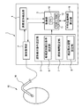
図1に示す心筋興奮波形検出装置1は、測定された心内心電図波形から所定の条件に適合する波形を取得する波形取得部2と、心筋興奮の波形を検出するための諸条件を設定する波形検出条件設定部3と、波形検出条件設定部3によって設定された条件に基づいて心筋興奮の波形を検出する興奮波形検出部4と、心筋興奮が伝導される平均伝導時間を算出する平均伝導時間算出部9と、これらの各部を制御する制御部5を備えている。
Embodiments of a myocardial excitation waveform detection device according to the present invention will be described below with reference to the accompanying drawings.
The myocardial excitation
また、波形検出条件設定部3は、心筋興奮の波形の候補波形を検出するための条件を設定する候補波形検出条件設定部6と、候補波形の中から心筋興奮の波形を探索するための探索期間を設定する探索期間設定部7と、候補波形を心筋興奮の波形として検出しないための検出除外期間を設定する検出除外期間設定部8を備えている。
The waveform detection
また、図1に示す15は、心房内の心内心電図が測定されている心臓を模式的に示したものであり、末梢血管から心臓カテーテル16が心房内に挿入されて、心臓カテーテル16に付設されている電極(図示せず)により心内心電図波形が取得される。取得された心内心電図波形のデータは、心臓カテーテル16を介して心筋興奮波形検出装置1に送られ、心筋興奮波形検出装置1の波形取得部2によって取得される。
Further, 15 shown in FIG. 1 schematically shows a heart whose intracardiac electrocardiogram in the atrium is measured. A
波形取得部2は、制御部5から送信される波形取得制御信号に基づいて心内心電図波形のデータを取得する。波形取得制御信号には心内心電図波形データを取得するタイミング、取得期間等の制御信号が含まれている。本発明の波形解析期間は、心内心電図波形データの取得期間の一例であり、予め設定された波形解析期間が取得期間の制御信号として制御部5から波形取得部2へ送信される。この制御信号を受信した波形取得部2は、取得タイミングから波形解析期間内の心内心電図波形データを取得する。取得された心内心電図波形データは、興奮波形検出部4へ送信されるとともに、制御部5に搭載されているRAM12に記憶保持される。
The waveform acquisition unit 2 acquires intracardiac electrocardiogram waveform data based on the waveform acquisition control signal transmitted from the control unit 5. The waveform acquisition control signal includes control signals such as a timing for acquiring intracardiac electrocardiogram waveform data, an acquisition period, and the like. The waveform analysis period of the present invention is an example of an acquisition period of intracardiac electrocardiogram waveform data, and a preset waveform analysis period is transmitted from the control unit 5 to the waveform acquisition unit 2 as a control signal for the acquisition period. The waveform acquisition unit 2 that has received this control signal acquires intracardiac electrocardiogram waveform data within the waveform analysis period from the acquisition timing. The acquired intracardiac electrocardiogram waveform data is transmitted to the excitement
波形検出条件設定部3は、波形取得部2によって取得された心内心電図波形データ取得期間内(例えば、波形解析期間内)の波形の中から、心筋に興奮(興奮波の電気信号)が発生していることを示す心筋興奮の波形を検出するための条件を設定する。
The waveform detection
波形検出条件設定部3に具備された候補波形検出条件設定部6は、心筋興奮の波形の候補波形を検出するために、波形の外形に関するデータに基づいて検出条件を設定する。例えば、波形解析期間内に存在する心内心電図波形が示す電位の横幅と縦幅に関するデータを検出条件として設定する。図2(a)に示す波形は、取得された心内心電図波形データの一例を示すものであり、検出条件として設定される波形(電位)の横幅および縦幅は、それぞれ矢印幅d1およびh1のように定められている。具体的には、例えば、心内心電図波形の横幅d1が10msec以下、縦幅h1が0.1mV以上であることを心筋興奮の波形の候補波形を検出するための検出条件として設定する。設定された候補波形検出条件としての波形の外形に関するデータは、制御部5へ送信され制御部5に搭載されているRAM12に記憶保持される。
The candidate waveform detection condition setting unit 6 provided in the waveform detection
候補波形検出条件としての波形の外形に関するデータは、制御部5から興奮波形検出部4へ送信される。興奮波形検出部4は、候補波形検出条件に適合する波形を、波形取得部2が取得した心内心電図波形データの中から検出し、検出した波形を心筋興奮の候補波形として決定する。
Data relating to the outer shape of the waveform as the candidate waveform detection condition is transmitted from the control unit 5 to the excitement
波形検出条件設定部3に具備された探索期間設定部7は、候補波形検出条件設定部6によって設定された波形の外形に関するデータに基づく検出条件に適合し、心筋興奮の候補波形として興奮波形検出部4によって検出された心内心電図波形の中から、心筋興奮の波形を探索するために探索期間を設定する。探索期間は、ノイズ波形を心筋興奮の波形として検出する誤検出を抑制するために設定される期間である。探索期間は、検出除外期間(後述する)よりも短い期間に設定される。設定された探索期間に関するデータは制御部5に送信され、制御部5に搭載されているRAM12に記憶保持される。
The search
また、探索期間に関するデータは、制御部5から興奮波形検出部4へ送信される。興奮波形検出部4は、探索期間内に存在している心筋興奮の候補波形の最大P−P値(波形の正の最も高い値から、負の最も高い値までの値のこと)を測定する。測定された最大P−P値に基づくデータが、心筋興奮の波形を探索する条件として設定される。具体的には、探索期間内に存在する心筋興奮の候補波形の中で最大P−P値を有する候補波形を探索することが条件として設定される。そして、興奮波形検出部4は、探索により検出された最大P−P値を有する候補波形を心筋興奮の波形として確定する。このように探索期間を設定することにより、探索期間内に複数の候補波形が存在する場合には、最大P−P値を有する候補波形のみを心筋興奮の波形として確定することができるので、ノイズ波形を心筋興奮の波形として検出する誤検出を抑制することができる。
Further, data related to the search period is transmitted from the control unit 5 to the excitement
また、確定された心筋興奮の波形に関するデータは制御部5に送信され、制御部5に搭載されているRAM12に記憶保持される。図2(b)は、設定された探索期間を模式的に表した図である。興奮波形検出部4によって最初に検出された心筋興奮の候補波形21のピーク(○印)22から□印23までの矢印24の期間を探索期間として設定する。この期間内に存在する最大P−P値を有する候補波形を心筋興奮の波形として確定する。図2(b)の場合には、探索期間24内に一つの候補波形21のみが存在するため、この候補波形21が心筋興奮の波形として確定される。
Data regarding the determined myocardial excitation waveform is transmitted to the control unit 5 and stored and held in the
波形検出条件設定部3に具備された検出除外期間設定部8は、興奮波形検出部4によって検出された候補波形の中から心筋興奮の波形を検出した場合に、検出後の予め設定された期間を心筋興奮の検出を行わない検出除外期間として設定する。検出除外期間は、ノイズ波形を含む候補波形のダブルカウントを防止するために設けられた期間である。検出除外期間は、心臓の局所活性を行う周期を生理学的に判断して例えば50msecに設定することができる。
The detection exclusion period setting unit 8 included in the waveform detection
設定された検出除外期間に関するデータは制御部5に送信され、制御部5に搭載されているRAM12に記憶保持される。図2(c)は、設定された検出除外期間を模式的に表した図である。興奮波形検出部4によって確定された心筋興奮の波形25のピーク(○印)26から△印27までの矢印28の期間を検出除外期間として設定する。この期間内に存在する心筋興奮の候補波形は、解析対象から除外する。図2(c)の場合には、検出除外期間28内に心筋興奮の波形25のみが存在し、それ以外に候補波形は存在しないので、解析除外となる対象波形も存在していない。
Data relating to the set detection exclusion period is transmitted to the control unit 5 and stored in the
なお、波形検出条件設定部3(候補波形検出条件設定部6、探索期間設定部7、検出除外期間設定部8を含む)によって設定される条件の内容は、外部から設定変更することが可能であり、波形検出条件設定部3に接続されて装備される設定条件入力手段(図示省略)によって入力変更するようにしてもよい。
The contents of the conditions set by the waveform detection condition setting unit 3 (including the candidate waveform detection condition setting unit 6, the search
興奮波形検出部4は、波形検出条件設定部3(候補波形検出条件設定部6、探索期間設定部7、検出除外期間設定部8)によって設定された条件を満たす候補波形を、制御部5から送信される検出制御信号に基づき心筋興奮の波形として検出する。また、興奮波形検出部4は、設定された条件に基づいて、上述したような心筋興奮の候補波形を決定する機能や心筋興奮の波形を確定する機能等も有している。興奮波形検出部4によって検出、確定等された各データは制御部5に送信され、制御部5に搭載されているRAM12に記憶保持される。
The excitement
平均伝導時間算出部9は、制御部5から送信される算出制御信号に基づいて、興奮波形検出部4によって検出された複数の心筋興奮の波形のデータから、心筋興奮が伝導される平均伝導時間を算出する。心筋興奮が伝導される時間とは、検出された各心筋興奮の波形間の時間のことをいい、この時間の平均値のことを平均伝導時間としている。平均伝導時間算出部9によって算出された平均伝導時間のデータは制御部5に送信され、制御部5に搭載されているRAM12に記憶保持される。
Based on the calculation control signal transmitted from the control unit 5, the average conduction
制御部5は、波形検出条件設定部3(候補波形検出条件設定部6、探索期間設定部7、検出除外期間設定部8)によって設定された条件に基づいて、心筋興奮波形検出装置1の各部(波形取得部2、興奮波形検出部4、平均伝導時間算出部9)を制御するものである。制御部5は、制御を司るCPU10、CPUに係る各種処理手順を実行するプログラムが保持されたROM11、CPUのワークエリアとして各部(取得部、設定部、検出部、算出部等)における各種データを格納するRAM12を備えている。
Based on the conditions set by the waveform detection condition setting unit 3 (candidate waveform detection condition setting unit 6, search
以上のような構成を有することにより、ノイズ波形の誤検出を抑制することができ、心筋興奮の波形の検出制度を向上させることができるので、正確な心筋興奮の伝導時間を測定することができ、より正しい平均伝導時間を算出することができる。また、この心筋興奮波形検出装置の機能は、リアルタイムで心筋興奮波形の解析を行う場合にも、再検討および論評等で心筋興奮波形の解析を行う場合にも有効である。 By having the configuration as described above, it is possible to suppress erroneous detection of noise waveforms and improve the detection system of myocardial excitation waveforms, so that accurate myocardial excitation conduction time can be measured. A more accurate average conduction time can be calculated. The function of the myocardial excitement waveform detection device is effective not only when analyzing the myocardial excitement waveform in real time, but also when analyzing the myocardial excitement waveform by review and review.
次に、図3に示すフローチャートに沿って心筋興奮波形検出処理の処理手順を説明する。なお、この処理手順の説明に際して、心筋興奮の波形を検出する手順を示す図4を参照しながら説明する。 Next, a processing procedure of myocardial excitation waveform detection processing will be described along the flowchart shown in FIG. Note that this processing procedure will be described with reference to FIG. 4 showing a procedure for detecting a myocardial excitation waveform.
心筋興奮波形の検出処理が開始されると、最初に、心筋興奮の波形を検出するための各パラメータの設定が行われる(ステップS101)。例えば、候補波形検出条件設定部6によって設定される、心筋興奮の波形の候補波形を検出するための波形の外形データに基づくパラメータを設定する。具体的には、波形取得部2が取得した心内心電図波形(電位)の横幅を10msec以下、縦幅を0.1mV以上として設定する。また、検出除外期間設定部8によって設定される、いずれの候補波形も心筋興奮の波形として検出しない検出除外期間(解析対象の除外期間)に関するパラメータを設定する。具体的には、検出除外期間を50msecに設定する。また、探索期間設定部7によって設定される、心筋興奮の波形を探索するための探索期間に関するパラメータを設定する。具体的には、探索期間を49msecに設定する。このとき、探索期間は、検出除外期間よりも短い時間に設定する。
When the myocardial excitation waveform detection process is started, first, parameters for detecting the myocardial excitation waveform are set (step S101). For example, a parameter based on waveform external data for detecting a candidate waveform of the myocardial excitation waveform set by the candidate waveform detection condition setting unit 6 is set. Specifically, the horizontal width of the intracardiac electrocardiogram waveform (potential) acquired by the waveform acquisition unit 2 is set to 10 msec or less and the vertical width is set to 0.1 mV or more. In addition, a parameter related to a detection exclusion period (exclusion period to be analyzed) that is not detected as a myocardial excitation waveform set by the detection exclusion period setting unit 8 is set. Specifically, the detection exclusion period is set to 50 msec. In addition, a parameter related to a search period for searching for a myocardial excitation waveform set by the search
ここで、図4に示す波形は、心房細動が発生している期間に測定された心内心電図波形から、波形取得部2によって取得された波形解析期間内の波形の一部の波形である。波形解析期間は、予め設定された期間(ここでは、5secに設定されている)であり、制御部5から波形取得部2に対して解析制御信号として送信される。波形取得部2は、この解析制御信号に基づいて5sec間の波形を取得する。 Here, the waveform shown in FIG. 4 is a waveform of a part of the waveform in the waveform analysis period acquired by the waveform acquisition unit 2 from the intracardiac electrocardiogram waveform measured during the period in which atrial fibrillation is occurring. . The waveform analysis period is a preset period (here, set to 5 seconds), and is transmitted from the control unit 5 to the waveform acquisition unit 2 as an analysis control signal. The waveform acquisition unit 2 acquires a waveform for 5 seconds based on this analysis control signal.
続いて、波形取得部2によって取得された波形解析期間内に発生した心内心電図波形の中から、S101で設定した横幅(10msec以下)と縦幅(0.1mV以上)の条件に適合する波形を心筋興奮の候補波形として全て検出する(ステップS102)。なお、ステップS102は、本発明に係る波形取得手順の一例である。図4では、心筋興奮の候補波形として破線四角形31から37に含まれている7個の波形が検出された。
Subsequently, from the intracardiac electrocardiogram waveform generated within the waveform analysis period acquired by the waveform acquisition unit 2, a waveform that meets the conditions of the horizontal width (10 msec or less) and the vertical width (0.1 mV or more) set in S101. Are all detected as candidate waveforms of myocardial excitation (step S102). Step S102 is an example of a waveform acquisition procedure according to the present invention. In FIG. 4, seven waveforms included in broken-
続いて、ステップS102で検出した心筋興奮の候補波形の中から心筋興奮の波形を選定する(ステップS103)。図4において、最初に検出した候補波形(破線四角形31に含まれる波形)のP−P値を興奮波形検出部4によって測定する。次に、○印31aから探索期間(49msec)経過後の□印31bまでの期間に他の候補波形(破線四角形に含まれる波形)が存在するか探索する。図4では、破線四角形31に含まれる候補波形以外の他の候補波形が存在しないので、破線四角形31に含まれる波形を最初の心筋興奮の波形として確定する。そして、確定した心筋興奮の波形の最初のピーク(○印31a)から検出除外期間(50msec)経過後の△印31cまでの期間を、いずれの波形も検出しない解析対象の除外期間とする。
Subsequently, a myocardial excitation waveform is selected from the candidate myocardial excitation waveforms detected in step S102 (step S103). In FIG. 4, the excitation
解析対象の除外期間が経過した後は、経過後(△印31c以後)の最初に検出した候補波形(破線四角形32に含まれる波形)のP−P値を興奮波形検出部4によって測定する。次に、○印32aから探索期間(49msec)経過後の□印32bまでの期間に他の候補波形(破線四角形に含まれる波形)が存在するか探索し、存在する場合にはその候補波形のP−P値を測定して破線四角形32に含まれる波形のP−P値と比較する。図4では、○印32aから□印32bまでの期間に他の候補波形(破線四角形33に含まれる波形)が存在するので、そのP−P値を測定して、破線四角形32に含まれる波形のP−P値と比較する。探索期間内に複数の候補波形が存在する場合には、P−P値が最も大きい候補波形を検出し心筋興奮の波形として確定する。破線四角形32に含まれる波形のP−P値と破線四角形33に含まれる波形のP−P値とを比較すると、図4からも明らかなように破線四角形33に含まれる波形のP−P値の方が破線四角形32に含まれる波形のP−P値よりも大きいので、破線四角形33に含まれる候補波形を心筋興奮の波形として確定する。複数の候補波形を比較して、最も大きいP−P値の波形を心筋興奮の波形とするのは、心内心電図波形を取得する電極(図示せず)に最も近位の心内心電図波形を心筋興奮の波形とするためである。心筋興奮の波形として確定されなかった破線四角形32に含まれる波形は、以後、心筋興奮が伝導される平均伝導時間を算出するための波形としては使用されない。そして、確定した心筋興奮の波形の最初のピーク(○印33a)から検出除外期間(50msec)経過後の△印33cまでの期間を、いずれの波形も検出しない解析対象の除外期間とする。以上の検出処理を波形解析期間が終了するまで繰り返し、心筋興奮の波形を繰り返し検出する。
After the analysis exclusion period has elapsed, the
続いて、心筋興奮の波形の検出終了後に、選定した心筋興奮の波形内の−dv/dtポイントを検出する(ステップS104)。図4では、破線で示される31d、33d、34d、36d、37dのポイントが検出される。なお、波形内の検出ポイントは、−dv/dtポイントに限定されず、dv/dtポイントを検出するようにしてもよい。 Subsequently, after the detection of the myocardial excitation waveform is completed, a -dv / dt point in the selected myocardial excitation waveform is detected (step S104). In FIG. 4, points 31d, 33d, 34d, 36d, and 37d indicated by broken lines are detected. The detection point in the waveform is not limited to the −dv / dt point, and the dv / dt point may be detected.
続いて、ステップS104で検出した−dv/dtポイント間の時間、即ち、心筋興奮が伝導される伝導時間を測定し、測定した各伝導時間から平均伝導時間を算出する(ステップS105)。図4では、ポイント31d−33d間、ポイント33d−34d間、ポイント34d−36d間、ポイント36d−37d間の時間が、それぞれ心筋興奮の伝導される伝導時間41、42、43、44として測定され、これらの伝導時間から平均伝導時間が算出される。
Subsequently, the time between −dv / dt points detected in step S104, that is, the conduction time during which myocardial excitation is conducted is measured, and the average conduction time is calculated from each measured conduction time (step S105). In FIG. 4, the times between
次に、心房細動中の心内心電図波形(図5(a)参照)に対して、従来の解析方法(非特許文献1に記載の解析方法)を実行して平均伝導時間を算出した結果(図5(b)参照)と、上述した本発明の解析方法を実行して平均伝導時間を算出した結果(図5(c)参照)について説明する。 Next, the result of calculating the average conduction time by executing the conventional analysis method (analysis method described in Non-Patent Document 1) on the intracardiac electrocardiogram waveform during atrial fibrillation (see FIG. 5A). (See FIG. 5B) and the result of calculating the average conduction time by executing the analysis method of the present invention described above (see FIG. 5C) will be described.
波形の検出条件に関する各パラメータは、横幅を10msec以下、縦幅を0.1mV以上、検出除外期間を50msec、探索期間を49msecに設定した。 The parameters relating to the waveform detection conditions were set such that the horizontal width was 10 msec or less, the vertical width was 0.1 mV or more, the detection exclusion period was 50 msec, and the search period was 49 msec.
図5(b)中の符号Aと符号Bは、ノイズ波形が波形の外形の条件を満たしたため、心筋興奮の波形として検出されてしまった箇所を示している。符号Aが示すノイズ波形の後方には真の心筋興奮の波形があるが、検出除外期間の影響で、真の心筋興奮の波形が検出されていないことが確認できる。また、符号Bのノイズ波形の後方では真の心筋興奮の波形が検出されており、ノイズ波形と真の興奮波形の両方が検出(いわゆる、ダブルカウント)されていることが確認できる。 Symbols A and B in FIG. 5B indicate locations where the noise waveform has been detected as a waveform of myocardial excitement because the waveform of the noise satisfies the waveform outer condition. Although there is a true myocardial excitation waveform behind the noise waveform indicated by symbol A, it can be confirmed that the true myocardial excitation waveform has not been detected due to the influence of the detection exclusion period. In addition, a true myocardial excitement waveform is detected behind the noise waveform of B, and it can be confirmed that both the noise waveform and the true excitement waveform are detected (so-called double counting).
このように、従来の解析方法に基づいて心筋興奮の波形を検出して、検出された心筋興奮の波形から平均伝導時間を算出した結果、平均伝導時間は96msecとなった。ノイズ波形と真の興奮波形の両方が検出された箇所については、波形の間隔が短く伝導時間が短いため、ノイズ波形の影響の結果、平均伝導時間が真の値より小さくなっていると推察できる。また、真の興奮波形の代わりにノイズ波形が検出された箇所についても、算出される平均伝導時間の精度に影響していると推察できる。 As described above, the waveform of myocardial excitation was detected based on the conventional analysis method, and the average conduction time was calculated from the detected waveform of myocardial excitation. As a result, the average conduction time was 96 msec. For locations where both noise waveforms and true excitement waveforms are detected, the interval between the waveforms is short and the conduction time is short, so it can be inferred that the average conduction time is less than the true value as a result of the noise waveform. . Further, it can be inferred that the location where the noise waveform is detected instead of the true excitement waveform also affects the accuracy of the calculated average conduction time.
一方、本発明の解析方法を実行した場合は、図5(c)に示されるように、ノイズ波形の誤検出が大幅に低減され、検出波形のほとんどが真の心筋興奮の波形となっている。検出された心筋興奮の波形から平均伝導時間を算出した結果、平均伝導時間は112msecとなり、ノイズ波形の影響が取り除かれていることが確認できた。すなわち、従来の解析方法よりも精度良く平均伝導時間を算出できることが確認できた。 On the other hand, when the analysis method of the present invention is executed, as shown in FIG. 5C, the erroneous detection of the noise waveform is greatly reduced, and most of the detected waveforms are true myocardial excitation waveforms. . As a result of calculating the average conduction time from the detected myocardial excitation waveform, the average conduction time was 112 msec, and it was confirmed that the influence of the noise waveform was removed. That is, it was confirmed that the average conduction time can be calculated with higher accuracy than the conventional analysis method.
尚、本発明の実施の形態において説明した各処理手順を、一連の手順を備えた方法の発明としても、また、一連の手順をコンピュータに実行させるためのプログラムの発明としてもよい。その場合にも上記実施形態の効果と同様の効果を得ることができる。 Each processing procedure described in the embodiment of the present invention may be an invention of a method having a series of procedures, or an invention of a program for causing a computer to execute a series of procedures. In that case, the same effect as that of the above embodiment can be obtained.
例えば、心臓カテーテルによる心房細動治療の分野等に利用可能である。 For example, it can be used in the field of atrial fibrillation treatment using a cardiac catheter.
1:心筋興奮波形検出装置、2:波形取得部、3:波形検出条件設定部、4:興奮波形検出部、5:制御部、6:候補波形検出条件設定部、7:探索期間設定部、8:検出除外期間設定部、9:平均伝導時間算出部、10:CPU、11:ROM、12:RAM 1: myocardial excitation waveform detection device, 2: waveform acquisition unit, 3: waveform detection condition setting unit, 4: excitation waveform detection unit, 5: control unit, 6: candidate waveform detection condition setting unit, 7: search period setting unit, 8: detection exclusion period setting unit, 9: average conduction time calculation unit, 10: CPU, 11: ROM, 12: RAM
Claims (6)
前記波形取得部によって取得された前記波形解析期間内の波形の中から、心筋に興奮が発生していることを示す心筋興奮の波形を検出するための条件を設定する波形検出条件設定部と、
前記波形検出条件設定部によって設定された条件に基づいて、前記波形解析期間内の波形の中から心筋興奮の波形を検出する興奮波形検出部と、
を備え、
前記波形検出条件設定部は、
前記心筋興奮の波形の候補波形を検出するために波形の外形に基づいた条件を設定する候補波形検出条件設定部と、
前記波形の外形に基づいた条件で検出された前記候補波形から心筋興奮の波形を探索するための探索期間を設定する探索期間設定部と、
前記探索期間内において前記候補波形から心筋興奮の波形を検出した場合、当該検出後の予め設定された期間を、前記探索期間内において検出された前記心筋興奮の波形の後に続く前記候補波形を心筋興奮の波形として検出しない検出除外期間として設定する検出除外期間設定部と、
を備えることを特徴とする心筋興奮波形検出装置。 A waveform acquisition unit for acquiring a waveform within a preset waveform analysis period from an intracardiac electrocardiogram measured during the occurrence of atrial fibrillation;
A waveform detection condition setting unit for setting a condition for detecting a myocardial excitation waveform indicating that the myocardium is excited from the waveforms in the waveform analysis period acquired by the waveform acquisition unit;
Based on the conditions set by the waveform detection condition setting unit, an excitation waveform detection unit that detects a myocardial excitation waveform from waveforms within the waveform analysis period;
With
The waveform detection condition setting unit
A candidate waveform detection condition setting unit for setting a condition based on the outer shape of the waveform to detect the candidate waveform of the myocardial excitation waveform;
A search period setting unit for setting a search period for searching for a myocardial excitation waveform from the candidate waveforms detected under conditions based on the outer shape of the waveform;
When detecting the waveform of cardiac excitation from the candidate waveform in said search period, myocardial a preset period of time after the detection, the candidate waveform subsequent to said detected cardiac excitation wave in said search period A detection exclusion period setting unit that is set as a detection exclusion period that is not detected as a waveform of excitement,
A myocardial excitement waveform detection apparatus comprising:
前記候補波形として最初に取得した波形の前記発生時から予め設定された期間を心筋興奮探索期間とし、当該心筋興奮探索期間内の最大P−P値を有する候補波形を心筋興奮の波形として検出する心筋興奮検出手順と、
前記探索期間内において前記心筋興奮の波形として検出した候補波形の前記発生時から予め設定された期間を波形検出除外期間とし、当該波形検出除外期間内において、前記心筋興奮として検出された候補波形の後に続く候補波形を心筋興奮の波形として検出しない心筋興奮除外手順と、
をコンピュータに実行させるようにしたことを特徴とする心筋興奮波形検出プログラム。 Waveform acquisition that measures the size of the waveform generated within the preset waveform analysis period of the intracardiac electrocardiogram measured during the occurrence of atrial fibrillation, and acquires the waveform that meets the predetermined condition as a candidate waveform for myocardial excitation Procedure and
A period preset from the time of occurrence of the waveform first acquired as the candidate waveform is set as a myocardial excitation search period, and a candidate waveform having the maximum PP value within the myocardial excitation search period is detected as a waveform of myocardial excitation. Myocardial excitation detection procedure;
A period preset from the occurrence of the candidate waveform detected as the myocardial excitation waveform within the search period is defined as a waveform detection exclusion period, and the candidate waveform detected as the myocardial excitation within the waveform detection exclusion period. Myocardial excitation exclusion procedure that does not detect subsequent candidate waveforms as myocardial excitation waveforms,
A myocardial excitement waveform detection program characterized in that a computer is executed.
検出した複数の心筋興奮の波形に基づいて当該心筋興奮が伝導される平均伝導時間を算出する平均伝導時間算出手順と、
をコンピュータに実行させるようにしたことを特徴とする請求項5に記載の心筋興奮波形検出プログラム。 After the elapse of the waveform detection exclusion period, the procedure for repeatedly performing the myocardial excitation detection procedure and the myocardial excitation exclusion procedure,
An average conduction time calculation procedure for calculating an average conduction time through which the myocardial excitement is conducted based on a plurality of detected myocardial excitation waveforms;
6. The myocardial excitation waveform detection program according to claim 5, wherein the computer is executed.
Priority Applications (3)
| Application Number | Priority Date | Filing Date | Title |
|---|---|---|---|
| JP2012058748A JP5869925B2 (en) | 2012-03-15 | 2012-03-15 | Myocardial excitation waveform detection device and detection program |
| US13/785,800 US8825147B2 (en) | 2012-03-15 | 2013-03-05 | Cardiac muscle excitation waveform detector |
| EP13157938.5A EP2638852B1 (en) | 2012-03-15 | 2013-03-06 | Cardiac muscle excitation waveform detector |
Applications Claiming Priority (1)
| Application Number | Priority Date | Filing Date | Title |
|---|---|---|---|
| JP2012058748A JP5869925B2 (en) | 2012-03-15 | 2012-03-15 | Myocardial excitation waveform detection device and detection program |
Publications (3)
| Publication Number | Publication Date |
|---|---|
| JP2013188439A JP2013188439A (en) | 2013-09-26 |
| JP2013188439A5 JP2013188439A5 (en) | 2014-11-13 |
| JP5869925B2 true JP5869925B2 (en) | 2016-02-24 |
Family
ID=47832968
Family Applications (1)
| Application Number | Title | Priority Date | Filing Date |
|---|---|---|---|
| JP2012058748A Active JP5869925B2 (en) | 2012-03-15 | 2012-03-15 | Myocardial excitation waveform detection device and detection program |
Country Status (3)
| Country | Link |
|---|---|
| US (1) | US8825147B2 (en) |
| EP (1) | EP2638852B1 (en) |
| JP (1) | JP5869925B2 (en) |
Families Citing this family (9)
| Publication number | Priority date | Publication date | Assignee | Title |
|---|---|---|---|---|
| CN105592787B (en) * | 2013-10-30 | 2019-01-08 | 圣犹达医疗用品心脏病学部门有限公司 | The cardiac mapping system and method that two-way activation for electrogram detects |
| WO2015066322A1 (en) | 2013-11-01 | 2015-05-07 | Boston Scientific Scimed, Inc. | Cardiac mapping using latency interpolation |
| EP3116386A1 (en) * | 2014-03-11 | 2017-01-18 | Boston Scientific Scimed, Inc. | Medical devices for mapping cardiac tissue |
| US9681818B2 (en) | 2014-12-16 | 2017-06-20 | Biosense Webster (Israel) Ltd. | Detection and display of irregular periodic waveforms |
| US10226631B2 (en) | 2015-08-28 | 2019-03-12 | Cardiac Pacemakers, Inc. | Systems and methods for infarct detection |
| WO2017041890A1 (en) | 2015-09-07 | 2017-03-16 | Ablacon Inc. | Elongated medical device suitable for intravascular insertion and method of making an elongated medical device suitable for intravascular insertion |
| WO2017041892A1 (en) | 2015-09-07 | 2017-03-16 | Ablacon Inc. | System for analyzing electrophysiological data and method for analyzing electrophysiological data |
| JP6802445B2 (en) * | 2016-03-15 | 2020-12-16 | 国立大学法人滋賀医科大学 | Operation method of myocardial excitement discriminator and myocardial excitement discriminator |
| JP6433530B2 (en) * | 2017-03-23 | 2018-12-05 | 中山水熱工業株式会社 | Waveform analysis auxiliary device and waveform analysis auxiliary system |
Family Cites Families (11)
| Publication number | Priority date | Publication date | Assignee | Title |
|---|---|---|---|---|
| JPS59216282A (en) * | 1983-05-24 | 1984-12-06 | Advance Res & Dev Co Ltd | Living body signal processing system |
| JPS61100230A (en) * | 1984-10-24 | 1986-05-19 | 興和株式会社 | Method and apparatus for fabricating heart surface exciting propagation chart |
| FR2749765B1 (en) * | 1996-06-18 | 1998-10-02 | Ela Medical Sa | IMPLANTABLE DEFIBRILLATOR / CARDIOVERVER ACTIVE MEDICAL DEVICE WITH IMPROVED TACHYCARDIAL DISCRIMINATION |
| US6873870B2 (en) * | 2001-04-30 | 2005-03-29 | Medtronic, Inc. | Methods for adjusting cardiac detection criteria and implantable medical devices using same |
| US6978184B1 (en) * | 2002-07-29 | 2005-12-20 | Marcus Frank I | Optimization method for cardiac resynchronization therapy |
| US7437190B1 (en) | 2004-03-02 | 2008-10-14 | Pacesetter, Inc. | Cardiac stimulation device with adjustable blanking intervals |
| US7818056B2 (en) * | 2005-03-24 | 2010-10-19 | Cardiac Pacemakers, Inc. | Blending cardiac rhythm detection processes |
| US8038625B2 (en) * | 2005-09-15 | 2011-10-18 | St. Jude Medical, Atrial Fibrillation Division, Inc. | System and method for three-dimensional mapping of electrophysiology information |
| US8229545B2 (en) | 2005-09-15 | 2012-07-24 | St. Jude Medical, Atrial Fibrillation Division, Inc. | System and method for mapping complex fractionated electrogram information |
| US7907994B2 (en) | 2007-01-11 | 2011-03-15 | Biosense Webster, Inc. | Automated pace-mapping for identification of cardiac arrhythmic conductive pathways and foci |
| US8478393B2 (en) * | 2008-11-10 | 2013-07-02 | Cardioinsight Technologies, Inc. | Visualization of electrophysiology data |
-
2012
- 2012-03-15 JP JP2012058748A patent/JP5869925B2/en active Active
-
2013
- 2013-03-05 US US13/785,800 patent/US8825147B2/en active Active
- 2013-03-06 EP EP13157938.5A patent/EP2638852B1/en active Active
Also Published As
| Publication number | Publication date |
|---|---|
| JP2013188439A (en) | 2013-09-26 |
| EP2638852A1 (en) | 2013-09-18 |
| EP2638852B1 (en) | 2019-04-24 |
| US20130245476A1 (en) | 2013-09-19 |
| US8825147B2 (en) | 2014-09-02 |
Similar Documents
| Publication | Publication Date | Title |
|---|---|---|
| JP5869925B2 (en) | Myocardial excitation waveform detection device and detection program | |
| JP6675467B2 (en) | Apparatus for bipolar / unipolar hybrid detection of activated wavefronts | |
| CN106963367B (en) | Overall system and method for detecting region of interest | |
| US8918167B2 (en) | RI measurement/notification apparatus and measurement/notification program | |
| US8655435B2 (en) | Apparatus and method for generating atrial fibrillation prediction model, and apparatus and method for predicting atrial fibrillation | |
| JP6559439B2 (en) | Determination of reference annotation time from multi-channel ECG signals | |
| EP2713866B1 (en) | Classification of atrial fibrillation by determining an af complexity value | |
| CN104905785B (en) | ECG signal detection method and system | |
| JP2009540877A5 (en) | ||
| EP3139828B1 (en) | Detection of pulmonary vein isolation | |
| CN107049471B (en) | Non-overlapping ring or spline type catheter for determining activation source direction and activation source type | |
| JP6404784B2 (en) | Heart rate detection method and heart rate detection device | |
| Kholmovski et al. | Cardiac MRI and fibrosis quantification | |
| JP2014523779A5 (en) | System for predicting ventricular remodeling | |
| EP3821808B1 (en) | A method to find abnormal activations in intra-cardiac electrocardiograms | |
| JP6669455B2 (en) | Electrocardiogram analysis method, electrocardiogram analyzer, electrocardiogram analysis program, and computer-readable storage medium storing electrocardiogram analysis program | |
| US20210378577A1 (en) | Method and apparatus for analyzing electrocardio signal, and signal recorder and three-dimensional mapping system | |
| EP3326517B1 (en) | Method and system for identifying potential atrial flutter areas for medical decision support | |
| Beinart et al. | Role of magnetic resonance imaging in atrial fibrillation ablation | |
| JP6802445B2 (en) | Operation method of myocardial excitement discriminator and myocardial excitement discriminator | |
| US20230347141A1 (en) | Bystander atrium detection using coronary sinus (cs) signals | |
| US20240001127A1 (en) | Lead positioning for an implantable pulse generator | |
| Luongo et al. | B-PO05-151 AUTOMATIC CLASSIFICATION OF MACRO-REENTRANT ATRIAL TACHYCARDIA MECHANISMS USING 12-LEAD ECG | |
| CN115211953A (en) | Annotating slow Electrophysiological (EP) cardiac pathways related to Ventricular Tachycardia (VT) | |
| CN115361900A (en) | Implantable medical device for detecting atrial undersensing |
Legal Events
| Date | Code | Title | Description |
|---|---|---|---|
| A521 | Request for written amendment filed |
Free format text: JAPANESE INTERMEDIATE CODE: A523 Effective date: 20141001 |
|
| A621 | Written request for application examination |
Free format text: JAPANESE INTERMEDIATE CODE: A621 Effective date: 20141104 |
|
| A977 | Report on retrieval |
Free format text: JAPANESE INTERMEDIATE CODE: A971007 Effective date: 20150814 |
|
| A131 | Notification of reasons for refusal |
Free format text: JAPANESE INTERMEDIATE CODE: A131 Effective date: 20151006 |
|
| A521 | Request for written amendment filed |
Free format text: JAPANESE INTERMEDIATE CODE: A523 Effective date: 20151125 |
|
| TRDD | Decision of grant or rejection written | ||
| A01 | Written decision to grant a patent or to grant a registration (utility model) |
Free format text: JAPANESE INTERMEDIATE CODE: A01 Effective date: 20151215 |
|
| A61 | First payment of annual fees (during grant procedure) |
Free format text: JAPANESE INTERMEDIATE CODE: A61 Effective date: 20160108 |
|
| R150 | Certificate of patent or registration of utility model |
Ref document number: 5869925 Country of ref document: JP Free format text: JAPANESE INTERMEDIATE CODE: R150 |
|
| R250 | Receipt of annual fees |
Free format text: JAPANESE INTERMEDIATE CODE: R250 |
|
| R250 | Receipt of annual fees |
Free format text: JAPANESE INTERMEDIATE CODE: R250 |
|
| R250 | Receipt of annual fees |
Free format text: JAPANESE INTERMEDIATE CODE: R250 |
|
| R250 | Receipt of annual fees |
Free format text: JAPANESE INTERMEDIATE CODE: R250 |