JP5867268B2 - Unevenness inspection apparatus and unevenness inspection method - Google Patents
Unevenness inspection apparatus and unevenness inspection method Download PDFInfo
- Publication number
- JP5867268B2 JP5867268B2 JP2012101419A JP2012101419A JP5867268B2 JP 5867268 B2 JP5867268 B2 JP 5867268B2 JP 2012101419 A JP2012101419 A JP 2012101419A JP 2012101419 A JP2012101419 A JP 2012101419A JP 5867268 B2 JP5867268 B2 JP 5867268B2
- Authority
- JP
- Japan
- Prior art keywords
- unevenness
- luminance
- color
- evaluation parameter
- inspection
- Prior art date
- Legal status (The legal status is an assumption and is not a legal conclusion. Google has not performed a legal analysis and makes no representation as to the accuracy of the status listed.)
- Active
Links
- 238000007689 inspection Methods 0.000 title claims description 292
- 238000000034 method Methods 0.000 title claims description 46
- 238000011156 evaluation Methods 0.000 claims description 179
- 238000004364 calculation method Methods 0.000 claims description 54
- 238000003384 imaging method Methods 0.000 claims description 52
- 238000012545 processing Methods 0.000 claims description 49
- 238000012937 correction Methods 0.000 claims description 30
- 230000008859 change Effects 0.000 claims description 28
- 230000008569 process Effects 0.000 claims description 23
- 239000003086 colorant Substances 0.000 claims description 10
- 230000035945 sensitivity Effects 0.000 claims description 10
- 230000000007 visual effect Effects 0.000 claims description 8
- 241000282414 Homo sapiens Species 0.000 description 15
- 241000282412 Homo Species 0.000 description 5
- 230000000694 effects Effects 0.000 description 5
- 238000006243 chemical reaction Methods 0.000 description 3
- 238000010586 diagram Methods 0.000 description 3
- 238000005516 engineering process Methods 0.000 description 3
- 238000007796 conventional method Methods 0.000 description 2
- 230000007423 decrease Effects 0.000 description 2
- 230000002950 deficient Effects 0.000 description 2
- 238000013461 design Methods 0.000 description 2
- 238000011161 development Methods 0.000 description 2
- 238000005401 electroluminescence Methods 0.000 description 2
- 238000012986 modification Methods 0.000 description 2
- 230000004048 modification Effects 0.000 description 2
- 238000012360 testing method Methods 0.000 description 2
- 230000009471 action Effects 0.000 description 1
- 230000000295 complement effect Effects 0.000 description 1
- 230000006872 improvement Effects 0.000 description 1
- 230000016507 interphase Effects 0.000 description 1
- 239000004973 liquid crystal related substance Substances 0.000 description 1
- 238000004519 manufacturing process Methods 0.000 description 1
- 238000005259 measurement Methods 0.000 description 1
- 229910044991 metal oxide Inorganic materials 0.000 description 1
- 150000004706 metal oxides Chemical class 0.000 description 1
- 238000007781 pre-processing Methods 0.000 description 1
- 238000013441 quality evaluation Methods 0.000 description 1
- 239000004065 semiconductor Substances 0.000 description 1
- 230000006641 stabilisation Effects 0.000 description 1
- 238000011105 stabilization Methods 0.000 description 1
- 230000004304 visual acuity Effects 0.000 description 1
Images


Classifications
-
- G—PHYSICS
- G01—MEASURING; TESTING
- G01J—MEASUREMENT OF INTENSITY, VELOCITY, SPECTRAL CONTENT, POLARISATION, PHASE OR PULSE CHARACTERISTICS OF INFRARED, VISIBLE OR ULTRAVIOLET LIGHT; COLORIMETRY; RADIATION PYROMETRY
- G01J3/00—Spectrometry; Spectrophotometry; Monochromators; Measuring colours
- G01J3/46—Measurement of colour; Colour measuring devices, e.g. colorimeters
- G01J3/50—Measurement of colour; Colour measuring devices, e.g. colorimeters using electric radiation detectors
- G01J3/506—Measurement of colour; Colour measuring devices, e.g. colorimeters using electric radiation detectors measuring the colour produced by screens, monitors, displays or CRTs
-
- G—PHYSICS
- G01—MEASURING; TESTING
- G01J—MEASUREMENT OF INTENSITY, VELOCITY, SPECTRAL CONTENT, POLARISATION, PHASE OR PULSE CHARACTERISTICS OF INFRARED, VISIBLE OR ULTRAVIOLET LIGHT; COLORIMETRY; RADIATION PYROMETRY
- G01J3/00—Spectrometry; Spectrophotometry; Monochromators; Measuring colours
- G01J3/46—Measurement of colour; Colour measuring devices, e.g. colorimeters
- G01J3/462—Computing operations in or between colour spaces; Colour management systems
-
- H—ELECTRICITY
- H04—ELECTRIC COMMUNICATION TECHNIQUE
- H04N—PICTORIAL COMMUNICATION, e.g. TELEVISION
- H04N17/00—Diagnosis, testing or measuring for television systems or their details
- H04N17/02—Diagnosis, testing or measuring for television systems or their details for colour television signals
Landscapes
- Physics & Mathematics (AREA)
- Spectroscopy & Molecular Physics (AREA)
- Engineering & Computer Science (AREA)
- General Physics & Mathematics (AREA)
- Theoretical Computer Science (AREA)
- Mathematical Physics (AREA)
- Signal Processing (AREA)
- Multimedia (AREA)
- General Health & Medical Sciences (AREA)
- Biomedical Technology (AREA)
- Health & Medical Sciences (AREA)
- Testing Of Optical Devices Or Fibers (AREA)
- Investigating Materials By The Use Of Optical Means Adapted For Particular Applications (AREA)
- Liquid Crystal (AREA)
- Manufacture Of Electron Tubes, Discharge Lamp Vessels, Lead-In Wires, And The Like (AREA)
- Devices For Indicating Variable Information By Combining Individual Elements (AREA)
- Spectrometry And Color Measurement (AREA)
- Image Analysis (AREA)
- Testing, Inspecting, Measuring Of Stereoscopic Televisions And Televisions (AREA)
Description
本開示は、カラー映像等におけるむら検査(色むら検査および輝度むら検査)を行うむら検査装置およびむら検査方法に関する。 The present disclosure relates to an unevenness inspection apparatus and an unevenness inspection method for performing unevenness inspection (color unevenness inspection and luminance unevenness inspection) in a color image or the like.
従来、カラー映像表示が可能なCRT(Cathode Ray Tube)やLCD(Liquid Crystal Display)等を用いた表示装置の量産工程における色むらや輝度むらの検査は、主に、限度見本との比較による官能検査を用いて行われている。この手法は、検査対象としての表示装置の表示画面を人間が直接視認することにより行われるため、実際の使用状態に近い検査であり、かつ簡便な手法である。 Conventionally, the inspection of uneven color and uneven brightness in the mass production process of a display device using a CRT (Cathode Ray Tube) or LCD (Liquid Crystal Display) capable of displaying color images has been mainly performed by comparison with limit samples. It is done using inspection. Since this method is performed by a human directly viewing the display screen of the display device as an inspection target, the method is an inspection close to the actual use state and is a simple method.
ところが、この手法では、個々の検査員の能力に頼る部分が大きいことから、検査員間の個人差や検査員の疲労の度合いなどによって検査品質が左右されてしまい、安定した検査をすることが困難である。 However, with this method, the part that relies on the ability of individual inspectors is large, so the inspection quality depends on individual differences between inspectors and the degree of fatigue of the inspectors, and stable inspections are possible. Have difficulty.
そこで、検査員の能力に頼らない客観的な色むらの検査手法がいくつか提案されている。例えば、表示画面全体を白色表示に設定した状態で、カラー撮像素子などを用いて表示画面内の複数箇所の色合いを測定し、白色表示部分との最大色差(ΔEuv*またはΔEab*)の値の大小に応じて色むら検査を行うというものである。 Therefore, several objective color unevenness inspection methods that do not depend on the ability of the inspector have been proposed. For example, in a state where the entire display screen is set to white display, a color image sensor or the like is used to measure the hue at a plurality of locations in the display screen, and the value of the maximum color difference (ΔEuv * or ΔEab * ) from the white display portion is measured. Color unevenness inspection is performed according to the size.
具体的には、例えば特許文献1〜3では、表示画面内の数点の色や明るさを測定し、そのばらつきや、最大値と最小値との差分などを規格化して、色むら検査に用いるようにしている。また、例えば特許文献4では、色むら領域の空間的な大きさや、色が変化している領域に着目し、それらを定量化して色むら検査に用いるようにしている。更に、例えば特許文献5では、R(赤),G(緑),B(青)の各輝度データに対して輝度むらを評価する手法が提案されている。
Specifically, in
ところが、上記特許文献1〜3の手法では、規格化したパラメータを用いた客観的な色むら検査によって、安定した検査の実現が期待できるものの、色むらの広がり方に応じて人間が感じる色むらの程度も変化してしまうという問題がある。また、同様に上記特許文献4の手法においても、色相によって人間が感じる色むらの程度が変化してしまうという問題がある。更に、特許文献5の手法では、輝度むらおよび色むらの双方が同時に生じている場合においてむらの評価を試みているものの、輝度むらおよび色むらに対する人間の感度が考慮されていない。このため、表示装置の品質を正確に評価するうえで、総合的なむらを評価するには至っていない。
However, in the methods of
すなわち、従来の手法では、人間による色むらや輝度むらの視感度に起因して、適切なむら検査(色むら検査および輝度むら検査)を行うのが困難であり、改善の余地があった。 That is, according to the conventional method, it is difficult to perform appropriate unevenness inspection (color unevenness inspection and uneven brightness inspection) due to human visibility of color unevenness and brightness unevenness, and there is room for improvement.
本開示はかかる問題点に鑑みてなされたもので、その目的は、従来と比べてより適切なむら検査を行うことが可能なむら検査装置およびむら検査方法を提供することにある。 The present disclosure has been made in view of such problems, and an object of the present disclosure is to provide an unevenness inspection apparatus and an unevenness inspection method capable of performing more appropriate unevenness inspection as compared with the related art.
本開示の第1のむら検査装置は、検査対象の撮像画像を取得するための撮像部と、撮像画像に基づいて、色むら検査用画像および輝度むら検査用画像をそれぞれ生成する画像生成部と、色むら検査用画像および輝度むら検査用画像の双方を用いて、色および輝度の双方に対するむら視感度を考慮して評価パラメータを算出する算出部と、算出された評価パラメータを用いてむら検査を行う検査部とを備えたものである。上記算出部は、色むら検査用画像を用いて色むら評価パラメータを算出すると共に、輝度むら検査用画像を用いて輝度むら評価パラメータを算出し、色むら評価パラメータと輝度むら評価パラメータとを重み付け加算することにより、上記評価パラメータとしての総合評価パラメータを算出する。また、上記色むら評価パラメータとして、検査対象の全領域に対する彩度エッジ領域の面積率である彩度エッジ面積率と、検査対象の全領域に対する色むら領域の面積率である色むら面積率とが少なくとも用いられる。
本開示の第2のむら検査装置は、検査対象の撮像画像を取得するための撮像部と、撮像画像に基づいて、色むら検査用画像および輝度むら検査用画像をそれぞれ生成する画像生成部と、色むら検査用画像および輝度むら検査用画像の双方を用いて、色および輝度の双方に対するむら視感度を考慮して評価パラメータを算出する算出部と、算出された評価パラメータを用いてむら検査を行う検査部とを備えたものである。上記算出部は、色むら検査用画像を用いて色むら評価パラメータを算出すると共に、輝度むら検査用画像を用いて輝度むら評価パラメータを算出し、色むら評価パラメータと輝度むら評価パラメータとを重み付け加算することにより、上記評価パラメータとしての総合評価パラメータを算出する。また、上記輝度むら評価パラメータとして、検査対象の全領域に対する輝度エッジ領域の面積率である輝度エッジ面積率と、検査対象の全領域に対する輝度むら領域の面積率である輝度むら面積率とが少なくとも用いられる。
First unevenness inspection apparatus of the present disclosure, an imaging unit for obtaining a captured image of the inspection object, an image generating unit based on the captured image to generate an image and luminance unevenness inspection image for color unevenness inspection respectively A calculation unit that calculates an evaluation parameter in consideration of uneven visual sensitivity with respect to both the color and the brightness using both the color unevenness inspection image and the brightness unevenness inspection image, and the unevenness inspection using the calculated evaluation parameter The inspection part which performs. The calculation unit calculates a color unevenness evaluation parameter using the color unevenness inspection image, calculates a brightness unevenness evaluation parameter using the brightness unevenness inspection image, and weights the color unevenness evaluation parameter and the brightness unevenness evaluation parameter. By adding, a comprehensive evaluation parameter as the evaluation parameter is calculated. Further, as the color unevenness evaluation parameter, the saturation edge area ratio that is the area ratio of the saturation edge area with respect to the entire area to be inspected, and the color unevenness area ratio that is the area ratio of the color uneven area with respect to the entire area to be inspected Is used at least.
The second unevenness inspection apparatus of the present disclosure includes an imaging unit for acquiring a captured image to be inspected, an image generation unit that generates a color unevenness inspection image and a luminance unevenness inspection image based on the captured image, and Using both the uneven color inspection image and the uneven brightness inspection image, a calculation unit that calculates an evaluation parameter in consideration of uneven visibility for both the color and the brightness, and an unevenness inspection using the calculated evaluation parameter And an inspection unit to be performed. The calculation unit calculates a color unevenness evaluation parameter using the color unevenness inspection image, calculates a brightness unevenness evaluation parameter using the brightness unevenness inspection image, and weights the color unevenness evaluation parameter and the brightness unevenness evaluation parameter. By adding, a comprehensive evaluation parameter as the evaluation parameter is calculated. Further, as the brightness unevenness evaluation parameter, at least a brightness edge area ratio that is an area ratio of the brightness edge area with respect to the entire area to be inspected and a brightness unevenness area ratio that is an area ratio of the brightness uneven area with respect to the entire area to be inspected Used.
本開示の第1のむら検査方法は、検査対象の撮像画像を取得するステップと、撮像画像に基づいて、色むら検査用画像および輝度むら検査用画像をそれぞれ生成する生成ステップと、色むら検査用画像および輝度むら検査用画像の双方を用いて、色および輝度の双方に対するむら視感度を考慮して評価パラメータを算出する算出ステップと、算出した評価パラメータを用いてむら検査を行う検査ステップとを含むようにしたものである。上記算出ステップでは、色むら検査用画像を用いて色むら評価パラメータを算出すると共に、輝度むら検査用画像を用いて輝度むら評価パラメータを算出し、色むら評価パラメータと輝度むら評価パラメータとを重み付け加算することにより、上記評価パラメータとしての総合評価パラメータを算出する。また、上記色むら評価パラメータとして、検査対象の全領域に対する彩度エッジ領域の面積率である彩度エッジ面積率と、検査対象の全領域に対する色むら領域の面積率である色むら面積率とが少なくとも用いられる。
本開示の第2のむら検査方法は、検査対象の撮像画像を取得するステップと、撮像画像に基づいて、色むら検査用画像および輝度むら検査用画像をそれぞれ生成する生成ステップと、色むら検査用画像および輝度むら検査用画像の双方を用いて、色および輝度の双方に対するむら視感度を考慮して評価パラメータを算出する算出ステップと、算出した評価パラメータを用いてむら検査を行う検査ステップとを含むようにしたものである。上記算出ステップでは、色むら検査用画像を用いて色むら評価パラメータを算出すると共に、輝度むら検査用画像を用いて輝度むら評価パラメータを算出し、色むら評価パラメータと輝度むら評価パラメータとを重み付け加算することにより、上記評価パラメータとしての総合評価パラメータを算出する。また、上記輝度むら評価パラメータとして、検査対象の全領域に対する輝度エッジ領域の面積率である輝度エッジ面積率と、検査対象の全領域に対する輝度むら領域の面積率である輝度むら面積率とが少なくとも用いられる。
First unevenness inspection method of the present disclosure includes the steps of obtaining a captured image of the inspection target, based on the captured image, a generation step of generating each image and luminance unevenness inspection image for color unevenness inspection, color unevenness inspection A calculation step for calculating an evaluation parameter in consideration of uneven visual sensitivity for both color and luminance using both the image for measurement and a luminance unevenness inspection image, and an inspection step for performing an unevenness inspection using the calculated evaluation parameter; the one in which was including so. In the calculation step, the color unevenness evaluation parameter is calculated using the color unevenness inspection image, the brightness unevenness evaluation parameter is calculated using the brightness unevenness inspection image, and the color unevenness evaluation parameter and the brightness unevenness evaluation parameter are weighted. By adding, a comprehensive evaluation parameter as the evaluation parameter is calculated. Further, as the color unevenness evaluation parameter, the saturation edge area ratio that is the area ratio of the saturation edge area with respect to the entire area to be inspected, and the color unevenness area ratio that is the area ratio of the color uneven area with respect to the entire area to be inspected Is used at least.
The second unevenness inspection method of the present disclosure includes a step of obtaining a captured image to be inspected, a generation step of generating a color unevenness inspection image and a luminance unevenness inspection image based on the captured image, and a color unevenness inspection A calculation step of calculating an evaluation parameter in consideration of uneven visibility for both color and luminance using both the image and the luminance unevenness inspection image, and an inspection step of performing an unevenness inspection using the calculated evaluation parameter It is what was included. In the calculation step, the color unevenness evaluation parameter is calculated using the color unevenness inspection image, the brightness unevenness evaluation parameter is calculated using the brightness unevenness inspection image, and the color unevenness evaluation parameter and the brightness unevenness evaluation parameter are weighted. By adding, a comprehensive evaluation parameter as the evaluation parameter is calculated. Further, as the brightness unevenness evaluation parameter, at least a brightness edge area ratio that is an area ratio of the brightness edge area with respect to the entire area to be inspected and a brightness unevenness area ratio that is an area ratio of the brightness uneven area with respect to the entire area to be inspected Used.
本開示のむら検査装置およびむら検査方法では、検査対象の撮像画像に基づいて色むら検査用画像および輝度むら検査用画像がそれぞれ生成され、これらの色むら検査用画像および輝度むら検査用画像の双方を用いて評価パラメータが算出され、この評価パラメータを用いてむら検査が行われる。ここで、評価パラメータを算出する際には、色および輝度の双方に対するむら視感度を考慮して算出される。これにより、そのような視感度を考慮せずにむら検査を行っている従来と比べ、人間の感覚により合致した客観的なむら検査(色むら検査および輝度むら検査)が実現される。 In the unevenness inspection apparatus and the unevenness inspection method of the present disclosure, an image for inspecting color unevenness and an image for inspecting unevenness in brightness are generated based on a captured image to be inspected, and both the image for inspecting unevenness in color and the image for inspecting unevenness in luminance are both displayed. Is used to calculate an evaluation parameter, and an unevenness inspection is performed using this evaluation parameter. Here, when the evaluation parameter is calculated, it is calculated in consideration of uneven visibility for both color and luminance. Accordingly, an objective unevenness inspection (color unevenness inspection and brightness unevenness inspection) that matches human senses is realized as compared with the conventional case where unevenness inspection is performed without considering such visibility.
本開示のむら検査装置およびむら検査方法によれば、色むら検査用画像および輝度むら検査用画像の双方を用いて評価パラメータを算出する際に、色および輝度の双方に対するむら視感度を考慮して算出するようにしたので、従来と比べ、人間の感覚により合致した客観的なむら検査を実現することができる。よって、従来と比べてより適切なむら検査を行うことが可能となる。 According to the unevenness inspection apparatus and the unevenness inspection method of the present disclosure, when the evaluation parameter is calculated using both the color unevenness inspection image and the brightness unevenness inspection image, the uneven visibility for both the color and the brightness is taken into consideration. Since the calculation is performed, it is possible to realize an objective nonuniformity inspection that matches the human sense as compared with the conventional case. Therefore, it is possible to perform a more appropriate unevenness inspection than in the past.
以下、本開示の実施の形態について、図面を参照して詳細に説明する。なお、説明は以下の順序で行う。
1.実施の形態(色および輝度の双方に対するむら視感度を考慮してむら検査を行う例)
2.変形例
Hereinafter, embodiments of the present disclosure will be described in detail with reference to the drawings. The description will be given in the following order.
1. Embodiment (Example of performing unevenness inspection in consideration of uneven visibility for both color and brightness)
2. Modified example
<実施の形態>
[むら検査装置の構成]
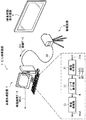
図1は、本開示の一実施の形態に係るむら検査装置(むら検査装置1)の概略構成を、検査対象としての表示装置4と共に表したものである。このむら検査装置1は、表示装置4等において表示されるカラー映像について、色むらの検査および輝度むらの検査を含めた総合的なむら検査を行うものであり、画像処理装置2および撮像装置3(撮像部)を備えている。ここで、表示装置4としては、例えば、CRTやLCD、PDP(Plasma Display Panel)、有機EL(Electro Luminescence)ディスプレイなどの各種のディスプレイを適用することが可能である。なお、本開示の一実施の形態に係るむら検査方法は、本実施の形態のむら検査装置1において具現化されるため、以下併せて説明する。
<Embodiment>
[Configuration of unevenness inspection equipment]
FIG. 1 illustrates a schematic configuration of an unevenness inspection apparatus (unevenness inspection apparatus 1) according to an embodiment of the present disclosure, together with a
(撮像装置3)
撮像装置3は、上記したむら検査における検査対象である、表示装置4の表示画面(カラー表示画面)を撮像するためのものである。この撮像装置3は、例えばCCD(Charge Coupled Devices)やCMOS(Complementary Metal Oxide Semiconductor)などからなる撮像素子を用いて構成されている。撮像装置3による撮像により得られた撮像画像(撮像データDin)は、接続配線10を介して画像処理装置2へ出力されるようになっている。なお、図1では、接続配線10が有線の配線である場合について示しているが、撮像装置3と画像処理装置2との間を無線で接続するようにしてもよい。
(Imaging device 3)
The
(画像処理装置2)
画像処理装置2は、撮像装置3から出力される撮像データDinに基づいてむら検査を行い、その検査結果としての検査結果データDoutを出力するものであり、例えば図に示したようなPC(Personal Computer)などを用いて構成されている。この画像処理装置2は、画像生成部21、パラメータ算出部22(算出部)および検査処理部23(検査部)を有している。
(Image processing apparatus 2)
The
画像生成部21は、撮像データDinに基づいて所定の画像処理を行うことにより、後述する色むら検査用画像および輝度むら検査用画像をそれぞれ生成するものである。具体的には、色むら検査用画像として、ここでは後述する、色むら画像(色むら画像データD11)、彩度エッジ画像(彩度エッジ画像データD12)および2値化色むら画像(2値化色むら画像データD13)をそれぞれ生成する。また、輝度むら検査用画像として、ここでは後述する、輝度むら画像(輝度むら画像データD21)、輝度エッジ画像(輝度エッジ画像データD22)および2値化輝度むら画像(2値化輝度むら画像データD23)をそれぞれ生成する。この際、画像生成部21は、色による色むら視感度の相違を考慮した補正処理(後述するゲイン補正処理)を行いつつ、上記した色むら検査用画像を生成するようになっている。なお、この画像生成部21における画像処理(画像生成処理)の詳細については後述する。
The
パラメータ算出部22は、画像生成部21により生成された色むら検査用画像(上記した各種の画像データD11〜D13)および輝度むら検査用画像(上記した各種の画像データD21〜D23)の双方を用いて、後述するむら検査の際の各種の評価パラメータを算出するものである。具体的には、色むら検査用画像(各種の画像データD11〜D13)を用いて、後述する色むら評価値Ec(色むらパラメータ)を算出する。また、輝度むら検査用画像(各種の画像データD21〜D23)を用いて、後述する輝度むら評価値El(輝度むら評価パラメータ)を算出する。そして、これらの色むら評価値Ecと輝度むら評価値Elとを重み付け加算することにより、上記した評価パラメータとしての総合評価値E(総合評価パラメータ)を算出する。この際、本実施の形態では、パラメータ算出部22は、色および輝度の双方に対するむら視感度を考慮して、総合評価値Eを算出するようになっている。なお、このパラメータ算出部22における算出処理の詳細についても後述する。
The
検査処理部23は、パラメータ算出部22において算出された総合評価値Eを用いて、検査対象である表示装置4の表示画面についてのむら検査(色むらの検査および輝度むらの検査を含めた総合的なむら検査)を行うものである。これにより、その検査結果としての検査結果データDoutが、検査処理部23から出力されるようになっている。なお、この検査処理部23におけるむら検査処理の詳細についても後述する。
The
[むら検査装置の作用・効果]
続いて、本実施の形態のむら検査装置1の作用および効果について説明する。
[Operation and effect of unevenness inspection device]
Then, the effect | action and effect of the
(1.基本動作)
このむら検査装置1では、撮像装置3によって検査対象である表示装置4の表示画面が撮像されると、撮像画像(撮像データDin)が得られる。この撮像データDinは、接続配線10を介して画像処理装置2内の画像生成部21へ入力される。
(1. Basic operation)
In this
画像生成部21は、撮像データDinに基づいて所定の画像処理を行うことにより、色むら検査用画像(各種の画像データD11〜D13)および輝度むら検査用画像(各種の画像データD21〜D23)をそれぞれ生成する。次いで、パラメータ算出部22は、これらの色むら検査用画像および輝度むら検査用画像の双方を用いて、むら検査の際の評価パラメータである統合評価値Eを算出する。そして、検査処理部23は、この総合評価値Eを用いて、検査対象である表示装置4の表示画面についてのむら検査を行う。これにより、その検査結果としての検査結果データDoutが、検査処理部23から出力される。
The
(2.むら検査処理の詳細)
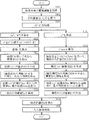
次に、本実施の形態のむら検査装置1における特徴的部分の1つである、画像処理装置2によるむら検査処理について詳細に説明する。図2は、この画像処理装置2において行うむら検査処理の一例を流れ図で表したものである。
(2. Details of unevenness inspection processing)
Next, the unevenness inspection process performed by the
(2−1.前処理)
まず、画像生成部21は、上記したように、撮像装置3から接続配線10を介して、検査対象の撮像画像(撮像データDin)を取得する(ステップS101)。
(2-1. Preprocessing)
First, as described above, the
次に、画像生成部21は、撮像データDinの信号を、三刺激値X,Y,Zからなる(Xi,Yi,Zi)信号に変換する(ステップS102)。具体的には、例えば撮像データDinがsRGB規格の映像信号である場合、以下の(1)式を用いて変換を行う。また、他の規格の映像信号の場合も、同様に規格に従って変換を行うことにより、(Xi,Yi,Zi)信号を生成する。なお、ここでは、撮像データDinの信号を(Xi,Yi,Zi)信号に変換する場合について説明しているが、撮像装置3によって直接、(Xi,Yi,Zi)信号を取得するようにしてもよい。
Next, the

そして、画像生成部21は、この(Xi,Yi,Zi)信号に対して、前処理としての所定のノイズ除去処理を行う(ステップS103)。具体的には、例えばMedian Filter等の空間フィルターを用いることにより、撮像装置3の種類や撮像条件に起因したノイズを除去する処理を行う。ただし、場合によっては、そのようなノイズ除去処理を行わないようにしてもよい。
Then, the
(2−2.色むら評価値Ecの算出)
続いて、画像生成部21およびパラメータ算出部22は、以下のようにして色むら評価値Ecを算出する(ステップS111〜S118)。
(2-2. Calculation of uneven color evaluation value Ec)
Subsequently, the
具体的には、まず、画像生成部21は、上記したノイズ除去処理後の(Xi,Yi,Zi)信号に基づいて、CIE(国際照明委員会)により1976年に勧告されたCIE1976 L*a*b*色空間(CIELAB色空間)における値である、(a*,b*)を算出する(ステップS111)。なお、このCIELAB色空間は、均等色空間として勧告されており、人間の知覚的な色の見えに対して均等性を考慮した空間となっている。ここで、画像生成部21は、具体的には以下の(2)式および(3)式を用いることにより、(a*,b*)を撮像画素(表示画素)ごとに算出する。なお、式中のXn,Yn,Znは、完全拡散反射面の三刺激値である。
Specifically, first, the
次に、画像生成部21は、各撮像画素において、色による色むら視感度の相違を考慮した補正処理(ゲイン補正処理)を行いつつ、前述した各種の色むら検査用画像を生成する。詳細には、各撮像画素においてそのような補正処理を行いつつ、彩度Cを算出する。具体的には、まず、画像生成部21は、ステップS111において算出したa*に対し、色むら視感度の相違を考慮した補正処理として、以下の(4)式により表わされるゲイン補正処理(ゲインαを用いた補正処理)を行う(ステップS112)。そして、画像生成部21は、ステップS111,S112において算出した(a*’,b*)を用いて、以下の(5)式により、彩度Cを撮像画素ごとに算出する(ステップS113)。
a*’=(α×a*)
(a*>0のとき:ゲインα>1、a*≦0のとき:ゲインα=1) ……(4)
C={(a*’)2+(b*)2}1/2
={(α×a*)2+(b*)2}1/2 ……(5)
Next, the
a * '= (α × a * )
(When a * > 0: Gain α> 1, When a * ≦ 0: Gain α = 1) (4)
C = {(a * ′) 2 + (b * ) 2 } 1/2
= {(Α × a * ) 2 + (b * ) 2 } 1/2 (5)
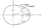
このようなゲイン補正処理は、例えば図3に示したような(a*,b*)座標系を考えると、(a*,b*)=(a1,b1)の点を、(a*,b*)=(α×a1,b1)の点に変換(補正)することに対応する。これにより、ゲイン補正処理前後における彩度Cを示す曲線は、図3中に示したようになる。すなわち、ゲイン補正処理前における彩度Cを示す曲線は円形状となっているのに対し、ゲイン補正処理後における彩度Cを示す曲線は、a*>0の領域において、図中の矢印で示したように、円形状ではなく惰円形状となっている。 Such gain correction process, for example as shown in FIG. 3 (a *, b *) Given the coordinate system, a point (a *, b *) = (a1, b1), (a *, This corresponds to conversion (correction) to a point of b * ) = (α × a1, b1). As a result, the curve indicating the saturation C before and after the gain correction processing is as shown in FIG. That is, the curve indicating the saturation C before the gain correction process is circular, whereas the curve indicating the saturation C after the gain correction process is indicated by an arrow in the figure in the region of a * > 0. As shown, it is not a circle but an ellipse.
ここで、このようなゲイン補正処理を行った後に彩度Cを算出するようにしているのは、以下の理由によるものである。すなわち、人間が感じる色むらの視感度(色むら視感度)が、色むらを構成する色の種類に応じて変化してしまうためである。 Here, the reason why the saturation C is calculated after performing such gain correction processing is as follows. That is, this is because the visibility of color unevenness (color unevenness visibility) perceived by humans changes according to the type of color constituting the color unevenness.
具体的には、まず、色むら視感度(ME値;人間によるむら(ここでは色むら)の主観評価値)には、色グループごとの色むら領域の面積率(検査対象の全領域(表示画面内の全ての表示画素領域)に対する色グループごとの色むら領域の面積率)によって、差異が生じる。すなわち、例えば図4(A)に示したように、赤(R)系、オレンジ(O)系およびマゼンダ(M)系の色に対応する色グループでの面積率ではそれぞれ、黄緑(YG)系、緑(G)系および水色(LB)系の色に対応する色グループでの面積率と比べ、同一の面積率の値におけるME値(色むら視感度)が高くなる。 Specifically, first, in the color unevenness visibility (ME value; subjective evaluation value of human unevenness (in this case, color unevenness)), the area ratio of the color unevenness area for each color group (all areas to be inspected (displayed) A difference occurs depending on the area ratio of the uneven color area for each color group with respect to all display pixel areas in the screen. That is, for example, as shown in FIG. 4A, the area ratios in the color groups corresponding to red (R), orange (O), and magenta (M) colors are respectively yellowish green (YG). Compared to the area ratios in the color groups corresponding to the green, green (G), and light blue (LB) colors, the ME value (color unevenness visibility) at the same area ratio value is increased.
また、色むら視感度(ME値)には、後述する最大彩度Cmax(色むら領域の全領域における最大彩度)を示す色が属する色グループによっても、差異が生じる。すなわち、例えば図4(B)に示したように、赤(R)系、オレンジ(O)系またはマゼンダ(M)系の色に対応する色グループに属する色が最大彩度Cmaxを示す場合には、黄緑(YG)系、緑(G)系または水色(LB)系の色に対応する色グループに属する色が最大彩度Cmaxを示す場合と比べ、同一の最大彩度Cmaxの値におけるME値(色むら視感度)が高くなる。 Further, the color unevenness visibility (ME value) also varies depending on the color group to which the color indicating the maximum saturation Cmax (maximum saturation in the entire color unevenness region) described later belongs. That is, for example, as shown in FIG. 4B, when a color belonging to a color group corresponding to a red (R), orange (O), or magenta (M) color exhibits the maximum saturation Cmax. Is the same maximum saturation Cmax value as compared with the case where a color belonging to a color group corresponding to a yellow-green (YG), green (G), or light blue (LB) color exhibits maximum saturation Cmax. The ME value (uneven color visibility) increases.
そこで、本実施の形態では画像生成部21において、上記したような色による色むら視感度の相違を考慮したゲイン補正処理を行いつつ、彩度Cを算出している。具体的には、色むら視感度が相対的に高い色グループ(赤(R)系、オレンジ(O)系およびマゼンダ(M)系の色に対応する色グループ)に対応するa*>0の領域について、選択的にa*の値を増加させる補正(ゲイン補正)を行う。これにより、色による色むら視感度の相違を考慮せずにむら検査(色むら検査)を行っている従来と比べ、人間の感覚により合致した客観的なむら検査が実現される。
Therefore, in the present embodiment, the
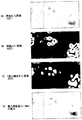
次に、画像生成部21は、このようにして算出された彩度Cを用いて、撮像画像から、色むら検査用画像の1つである色むら画像(色むら画像データD11)を生成する(ステップS114)。すなわち、撮像画素ごとの彩度Cの値からなる色むら画像を生成する。これにより、例えば図5(A)に示したような、色むら画像データD11からなる色むら画像が生成される。
Next, the
次いで、画像生成部21はまた、算出された彩度Cを用いて、撮像画像から、色むら検査用画像の1つである彩度エッジ画像(彩度エッジ画像データD12)を生成する(ステップS115)。具体的には、例えばSobelフィルター処理等を行うことによって彩度エッジ領域を特定し、彩度エッジ画像を生成する。これにより、例えば図5(B)に示したような、彩度エッジ画像データD12からなる彩度エッジ画像が生成される。
Next, the
ここで、このときに特定される彩度エッジ領域とは、例えば、検査対象(表示画面)における単位長さ当たりの彩度変化量(彩度エッジ強度)、または、単位視角当たりの彩度変化量が、所定の閾値(彩度エッジ閾値)以上となっている領域として定義される。具体的には、例えば図6(A)に示したように、人間が感じる色むらの感度に合うように表示画面40上の単位長さ当たりに対して定められた彩度エッジ閾値(例えば、(dC*/mm)=2.0)以上となっている領域(例えば図6(A)中の領域Ae)を、彩度エッジ領域として特定する。あるいは、例えば図6(B)に示したように、人間が感じる色むらの感度に合うように観察者(眼Ey)による単位視角θ当たりに対して定められた彩度エッジ閾値(例えば、(dC*/arcmin)=0.873)以上となっている領域(例えば図6(B)中の領域Ae)を、彩度エッジ領域として特定する。なお、このときの視角θとしては、例えば以下のようにして定義されたものを用いるのが望ましい。すなわち、人間の視力が1.0の場合には、人間が判別可能な角度の分解能は、1度の1/60である1分と定義されていることから、このような人間の視覚特性を考慮して1分を用いて定義されたものを用いるのが望ましい。この点は以下同様であるが、このような定義に限定されるものではない。
Here, the saturation edge region specified at this time is, for example, the amount of change in saturation per unit length (saturation edge intensity) in the inspection target (display screen) or the change in saturation per unit viewing angle. It is defined as a region where the amount is greater than or equal to a predetermined threshold (saturation edge threshold). Specifically, as shown in FIG. 6A, for example, a saturation edge threshold value (for example, for each unit length on the
続いて、画像生成部21は更に、生成された色むら画像(色むら画像データD11)を用いて2値化色むら画像(2値化色むら画像データD13)を生成し、色むら領域を特定する(ステップS116)。この際、各撮像画素における彩度Cの大きさに基づいて、色むら領域を特定する。具体的には、彩度Cの値が所定の閾値(例えば、2.0)以上である撮像画素については、色むら領域に属する撮像画素であると判断する一方、彩度Cの値が上記閾値未満である撮像画素については、色むら領域に属しない撮像画素であると判断することにより、色むら領域を特定する。これにより、例えば図5(C)に示した2値化色むら画像(2値化色むら画像データD13)のように、色むら領域が特定される。なお、この図5(C)に示した2値化色むら画像では、色むら領域が赤表示されると共に、それ以外の領域が黒表示されている(2値化画像となっている)。
Subsequently, the
次に、パラメータ算出部22は、このようにして生成された各種の色むら検査用画像(色むら画像データD11、彩度エッジ画像データD12および2値化色むら画像データD13)を用いて、以下説明する各種のパラメータを算出する(ステップS117)。
Next, the
具体的には、パラメータ算出部22は、彩度エッジ画像(彩度エッジ画像データD12)を用いて、検査対象の全領域(表示画面内の全ての表示画素領域)に対する彩度エッジ領域の面積率である、彩度エッジ面積率Sceを算出する。
Specifically, the
また、パラメータ算出部22は、2値化色むら画像(2値化色むら画像データD13)を用いて、検査対象の全領域(表示画面内の全ての表示画素領域)に対する色むら領域の面積率である、色むら面積率Scを算出する。
Further, the
更に、パラメータ算出部22は、色むら画像(色むら画像データD11)を用いて、色むら領域の全領域における最大彩度Cmaxを算出する。例えば、図5(A)に示した色むら画像の例では、図5(D)中に「×」印で示した撮像画素において、最大彩度Cmaxを示している。
Further, the
そして、パラメータ算出部22は、このようにして算出された、彩度エッジ面積率Sceと色むら面積率Scと最大彩度Cmaxとを重み付け加算することにより、色むら評価値Ecを算出する(ステップS118)。具体的には、パラメータ算出部22は、例えば以下の(6)式を用いることにより、色むら評価値Ecを算出する。なお、この(6)式において、定数(係数)k1,k2,k3はそれぞれ重み付け係数を表し、c1は所定の定数(0(ゼロ)を含む)を表している。
Ec=k1×Sce+k2×Sc+k3×Cmax+c1 ……(6)
Then, the
Ec = k1 * Sce + k2 * Sc + k3 * Cmax + c1 (6)
(2−3.輝度むら評価値Elの算出)
また、画像生成部21およびパラメータ算出部22は、以下のようにして輝度むら評価値Elを算出する(ステップS121〜S127)。
(2-3. Calculation of luminance unevenness evaluation value El)
In addition, the
具体的には、まず、画像生成部21は、前述したノイズ除去処理後の(Xi,Yi,Zi)信号に基づいて、前述したCIE1976 L*a*b*色空間(CIELAB色空間)における値である、L*(明度)を算出する(ステップS121)。具体的には、画像生成部21は以下の(7)式を用いることにより、L*を撮像画素ごとに算出する。
Specifically, first, the
![]()
![]()
次いで、画像生成部21は、白色画像の全領域(ここでは、表示装置4の表示画面に表示された白色画像の全ての表示画素領域)におけるL*の平均値である、平均輝度L*aveを算出する(ステップS122)。
Next, the
次に、画像生成部21は、このようにして算出されたL*および平均輝度L*aveを用いて、撮像画像から、輝度むら検査用画像の1つである輝度むら画像(輝度むら画像データD21)を生成する(ステップS123)。具体的には、撮像画素ごとのL*と平均輝度L*aveとの差分値である輝度差ΔL*(=L*−L*ave)を撮像画素ごとに算出し、この輝度差ΔL*からなる輝度むら画像を生成する。これにより、例えば図7(A)に示したような、輝度むら画像データD21からなる輝度むら画像が生成される。なお、このとき、上記のように輝度差ΔL*を用いて輝度むら画像を生成する代わりに、L*の値を用いて輝度むら画像を生成するようにしてもよい。
Next, the
次いで、画像生成部21はまた、算出されたL*を用いて、撮像画像から、輝度むら検査用画像の1つである輝度エッジ画像(輝度エッジ画像データD22)を生成する(ステップS124)。例えばSobelフィルター処理等を行うことによって輝度エッジ領域を特定し、輝度エッジ画像を生成する。これにより、例えば図7(B)に示したような、輝度エッジ画像データD22からなる輝度エッジ画像が生成される。
Next, the
ここで、このときに特定される輝度エッジ領域とは、例えば、検査対象(表示画面)における単位長さ当たりの輝度変化量(輝度エッジ強度)、または、単位視角当たりの輝度変化量が、所定の閾値(輝度エッジ閾値)以上となっている領域として定義される。具体的には、ここでも例えば図6(A)に示したように、表示画面40上の単位長さ当たりに対して定められた輝度エッジ閾値(例えば、(dL*/mm)=0.5)以上となっている領域(例えば図6(A)中の領域Ae)を、輝度エッジ領域として特定する。あるいは、例えば図6(B)に示したように、観察者(眼Ey)による単位視角θ当たりに対して定められた輝度エッジ閾値(例えば、(dL*/arcmin)=0.218)以上となっている領域(例えば図6(B)中の領域Ae)を、輝度エッジ領域として特定する。 Here, the luminance edge region specified at this time is, for example, a luminance change amount per unit length (luminance edge intensity) or a luminance change amount per unit viewing angle in the inspection target (display screen). Is defined as an area that is equal to or greater than a threshold value (luminance edge threshold value). Specifically, here again, for example, as shown in FIG. 6A, the brightness edge threshold value (for example, (dL * / mm ) = 0.5) determined per unit length on the display screen 40. ) The above region (for example, region Ae in FIG. 6A) is specified as the luminance edge region. Alternatively, as shown in FIG. 6B, for example, a luminance edge threshold value (for example, (dL * / arcmin) = 0.218) or more determined per unit viewing angle θ by the observer (eye Ey). A region (for example, a region Ae in FIG. 6B) is identified as a luminance edge region.
続いて、画像生成部21は更に、生成された輝度むら画像(輝度むら画像データD21)を用いて2値化輝度むら画像(2値化輝度むら画像データD23)を生成し、輝度むら領域(明暗部領域)を特定する(ステップS125)。この際、各撮像画素における輝度差ΔL*の大きさに基づいて、輝度むら領域を特定する。具体的には、輝度差ΔL*の値が所定の閾値(例えば、0.3)以上である撮像画素については、輝度むら領域に属する撮像画素であると判断する一方、輝度差ΔL*の値が上記閾値未満である撮像画素については、輝度むら領域に属しない撮像画素であると判断することにより、輝度むら領域を特定する。これにより、例えば図7(C)に示した2値化輝度むら画像(2値化輝度むら画像データD23)のように、輝度むら領域が特定される。なお、この図7(C)に示した2値化輝度むら画像では、輝度むら領域が白表示されると共に、それ以外の領域が黒表示されている(2値化画像となっている)。
Subsequently, the
次に、パラメータ算出部22は、このようにして生成された各種の輝度むら検査用画像(輝度むら画像データD21、輝度エッジ画像データD22および2値化輝度むら画像データD23)を用いて、以下説明する各種のパラメータを算出する(ステップS126)。
Next, the
具体的には、パラメータ算出部22は、輝度エッジ画像(輝度エッジ画像データD22)を用いて、検査対象の全領域(表示画面内の全ての表示画素領域)に対する輝度エッジ領域の面積率である、輝度エッジ面積率Sleを算出する。
Specifically, the
また、パラメータ算出部22は、2値化輝度むら画像(2値化輝度むら画像データD23)を用いて、検査対象の全領域(表示画面内の全ての表示画素領域)に対する輝度むら領域の面積率である、輝度むら面積率Slを算出する。
Further, the
更に、パラメータ算出部22は、輝度むら画像(輝度むら画像データD21)を用いて、輝度むら領域の全領域における最大輝度(最大のL*:L*max)と平均輝度L*aveとの差分値である、最大輝度差ΔL*max(=L*max−L*ave)を算出する。例えば、図7(A)に示した輝度むら画像の例では、図7(D)中に「×」印で示した撮像画素において、最大輝度差ΔL*maxを示している。
Further, the
そして、パラメータ算出部22は、このようにして算出された、輝度エッジ面積率Sleと輝度むら面積率Slと最大輝度差ΔL*maxとを重み付け加算することにより、輝度むら評価値Elを算出する(ステップS127)。具体的には、パラメータ算出部22は、例えば以下の(8)式を用いることにより、輝度むら評価値Elを算出する。なお、この(8)式において、定数(係数)k4,k5,k6はそれぞれ重み付け係数を表し、c2は所定の定数(0を含む)を表している。
El=k4×Sle+k5×Sl+k6×ΔL*max+c2 ……(8)
Then, the
El = k4 * Sle + k5 * Sl + k6 * [ Delta] L * max + c2 (8)
(2−4.総合評価値Eの算出・むら検査処理)
次に、パラメータ算出部22は、このようにして求められた色むら評価値Ecおよび輝度むら評価値Elに基づいて、例えば以下の(9)式を用いることにより、むら検査の際の総合評価値Eを算出する(ステップS131)。すなわち、色むら評価値Ecと輝度むら評価値Elとを重み付け加算することにより、総合評価値Eを算出する。これにより、以下説明するむら検査の際に、色むら評価値Ecと輝度むら評価値Elとの重み付けを反映させた検査を行うことが可能となる。なお、この(9)式において、定数(係数)A,Bはそれぞれ重み付け係数を表し、c3は所定の定数(0を含む)を表している。
E=A×Ec+B×El+c3 ……(9)
(2-4. Comprehensive evaluation value E calculation / unevenness inspection process)
Next, the
E = A * Ec + B * El + c3 (9)
ここで、本実施の形態では、パラメータ算出部22は、色および輝度の双方に対するむら視感度を考慮して、総合評価値Eを算出する。具体的には、上記した重み付け係数A,Bがそれぞれ、色および輝度の双方に対するむら視感度を考慮して決定されるようになっている。このように、総合評価値Eを算出する際に、色および輝度の双方に対するむら視感度を考慮して算出されることにより、そのような視感度を考慮せずにむら検査を行っている従来と比べ、人間の感覚により合致した客観的なむら検査が実現される。
Here, in the present embodiment, the
続いて、検査処理部23は、このようにして求められた総合評価値Eを用いて、検査対象である表示装置4の表示画面についてのむら検査を行い、その検査結果としての検査結果データDoutを生成する(ステップS132)。具体的には、例えば、総合評価値Eが大きくなるのに応じて、検査対象におけるむら(色むらおよび輝度むらのうちの少なくとも一方)の度合いが大きいと判断する。一方、総合評価値Eが小さくなるのに応じて、検査対象におけるむらの度合いが小さいと判断する。あるいは、総合評価値Eが所定の閾値以上である場合には、検査対象が不良品であると判断する一方、総合評価値Eが上記閾値未満である場合には、検査対象が良品であると判断する。以上により、画像処理装置2によるむら検査処理が終了となる。
Subsequently, the
(実施例1)
ここで、図8は、これまで説明した各種の評価値と人間による主観評価値(ME値)との関係(相間)を示す一実施例(実施例1)を表したものである。具体的には、図8(A)は、実施例1に係る色むら評価値Ecと主観評価値(ME値)との相間を表し、図8(B)は、実施例1に係る輝度むら評価値Elと主観評価値(ME値)との相間を表し、図8(C)は、実施例1に係る総合評価値Eと主観評価値(ME値)との相間を表している。なお、これらの図中に示した、線形直線における決定係数R2は、その値が「1」により近い大きい値となるのに従って、むら検査の精度がより高くなっていることを示す。
Example 1
Here, FIG. 8 shows an example (Example 1) showing a relationship (interphase) between various evaluation values described so far and a subjective evaluation value (ME value) by a human. Specifically, FIG. 8A illustrates the phase difference between the color unevenness evaluation value Ec and the subjective evaluation value (ME value) according to the first embodiment, and FIG. 8B illustrates luminance unevenness according to the first embodiment. The correlation between the evaluation value El and the subjective evaluation value (ME value) is shown. FIG. 8C shows the correlation between the comprehensive evaluation value E and the subjective evaluation value (ME value) according to the first embodiment. It should be noted that the determination coefficient R 2 in the linear line shown in these drawings indicates that the accuracy of the unevenness inspection is higher as the value thereof becomes a larger value closer to “1”.
まず、図8(A)に示した例は、主観評価は被験者として19歳〜24歳の男女各25名に対するマグニチュード推定法による評価結果に基づくものとなっている。また、この例では、彩度エッジ面積率Sceに対する重み付け係数k1=12.8、色むら面積率Scに対する重み付け係数k2=4.0、最大彩度Cmaxに対する重み付け係数k3=0.02として、色むら評価値Ecを算出している。この例では決定係数R2=0.94となっており、非常に高い相関を示していることが分かる。 First, in the example shown in FIG. 8A, the subjective evaluation is based on the evaluation result by the magnitude estimation method for 25 men and women of 19 to 24 years old as subjects. In this example, the weighting coefficient k1 = 12.8 for the saturation edge area ratio Sce, the weighting coefficient k2 = 4.0 for the color unevenness area ratio Sc, and the weighting coefficient k3 = 0.02 for the maximum saturation Cmax, The unevenness evaluation value Ec is calculated. In this example, the determination coefficient R 2 is 0.94, indicating that the correlation is very high.
一方、図8(B)に示した例は、図8(A)の場合と同様の条件によるマグニチュード推定法による評価結果に基づくものとなっている。また、この例では、輝度エッジ面積率Sleに対する重み付け係数k4=19.9、輝度むら面積率Slに対する重み付け係数k5=1.9、最大輝度差ΔL*maxに対する重み付け係数k6=0.19として、輝度むら評価値Elを算出している。この例においても決定係数R2=0.94となっており、非常に高い相関を示していることが分かる。 On the other hand, the example shown in FIG. 8B is based on the evaluation result by the magnitude estimation method under the same conditions as in the case of FIG. In this example, the weighting coefficient k4 = 19.9 for the luminance edge area ratio Sle, the weighting coefficient k5 = 1.9 for the luminance unevenness area ratio S1, and the weighting coefficient k6 = 0.19 for the maximum luminance difference ΔL * max. A luminance unevenness evaluation value El is calculated. Also in this example, the determination coefficient R 2 is 0.94, which shows that the correlation is very high.
他方、図8(C)に示した例も、図8(A)の場合と同様の条件によるマグニチュード推定法による評価結果に基づくものとなっている。また、この例では、色むら評価値Ecに対する重み付け係数A=0.63、輝度むら評価値Elに対する重み付け係数B=0.71として、総合評価値Eを算出している。この例においても決定係数R2=0.95となっており、非常に高い相関を示していることが分かる。 On the other hand, the example shown in FIG. 8C is also based on the evaluation result by the magnitude estimation method under the same conditions as in FIG. In this example, the overall evaluation value E is calculated with the weighting coefficient A = 0.63 for the color unevenness evaluation value Ec and the weighting coefficient B = 0.71 for the brightness unevenness evaluation value El. Also in this example, the determination coefficient R 2 is 0.95, which shows that the correlation is very high.
(実施例2)
また、図9および図10は、前述した単位長さ当たりの変化量または単位視角当たりの変化量と所定のエッジ閾値との比較によってエッジ領域(輝度エッジ領域)を特定する際の、エッジ領域の相違を対比して示す一実施例(実施例2)を表したものである。
(Example 2)
9 and 10 show the edge region when the edge region (luminance edge region) is specified by comparing the amount of change per unit length or the amount of change per unit viewing angle with a predetermined edge threshold. An example (Example 2) showing the difference in comparison is shown.
具体的には、図9(A)は、実施例2に係る、検査対象である表示画面のサイズ[inch]と、各サイズ(8,40,80inch)における観察者の適正視距離[mm]および1mm当たりの視角[°]との関係を表したものである。また、図9(B)は、図9(A)中に示した各適正視距離と1mm当たりの視角との関係を、模式的に表したものである。 Specifically, FIG. 9A illustrates the size [inch] of the display screen to be inspected and the appropriate viewing distance [mm] of the observer in each size (8, 40, 80 inches) according to the second embodiment. And the relationship with the viewing angle [°] per mm. FIG. 9B schematically shows the relationship between each appropriate viewing distance shown in FIG. 9A and the viewing angle per 1 mm.
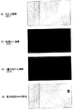
一方、図10は、図9(A),(B)中に示した各適正視距離(表示画面の各サイズ)について、輝度エッジ閾値として前述した(dL*/mm)=0.5を用いた場合の輝度エッジ画像(輝度エッジ画像データD22)と、前述した(dL*/arcmin)=0.218を用いた場合の輝度エッジ画像とを対比して表したものである。すなわち、輝度エッジ領域を、表示画面における単位長さ当たりの輝度変化量(輝度エッジ強度)を用いて定義した場合と、単位視角当たりの輝度変化量を用いて定義した場合とについて、特定されるエッジ領域の相違を対比して示している。 On the other hand, FIG. 10 uses the above-described (dL * / mm ) = 0.5 as the luminance edge threshold for each appropriate viewing distance (each size of the display screen) shown in FIGS. The luminance edge image (luminance edge image data D22) in the case where the image is detected is compared with the luminance edge image in the case where (dL * / arcmin) = 0.218 is used. That is, the case where the luminance edge region is defined using the luminance change amount per unit length (luminance edge intensity) on the display screen and the case where the luminance edge region is defined using the luminance change amount per unit viewing angle are specified. The difference between the edge regions is shown in comparison.
これらの図9および図10に示した実施例2により、単位視角当たりの輝度変化量を用いて輝度エッジ領域を定義した場合(輝度エッジ閾値:(dL*/arcmin)=0.218の場合)には、以下の効果も得られることが分かる。すなわち、表示画面における単位長さ当たりの輝度変化量を用いて輝度エッジ領域を定義した場合(輝度エッジ閾値:(dL*/mm)=0.5の場合)とは異なり、表示画面のサイズ(観察者の適正視距離)に依存せずに一定の輝度エッジ領域を特定することが可能となる。よって、むら検査の際の精度を向上させることができる。 When the luminance edge region is defined using the luminance change amount per unit viewing angle according to the second embodiment shown in FIGS. 9 and 10 (in the case of the luminance edge threshold: (dL * / arcmin) = 0.218). It can be seen that the following effects can also be obtained. That is, unlike the case where the luminance edge region is defined using the luminance change amount per unit length on the display screen (when the luminance edge threshold: (dL * / mm) = 0.5), the size of the display screen ( It is possible to specify a certain luminance edge region without depending on the observer's appropriate viewing distance. Therefore, the accuracy during the unevenness inspection can be improved.
なお、この実施例2では、輝度エッジ領域を特定する際のエッジ領域の相違について示したが、彩度エッジ領域を特定する際のエッジ領域の相違についても同様のことが言える。すなわち、単位視角当たりの彩度変化量を用いて彩度エッジ領域を定義した場合には、表示画面における単位長さ当たりの彩度変化量を用いて彩度エッジ領域を定義した場合とは異なり、表示画面のサイズ(観察者の適正視距離)に依存せずに一定の彩度エッジ領域を特定することが可能となる。 In the second embodiment, the difference in the edge region when specifying the luminance edge region is shown, but the same can be said for the difference in the edge region when specifying the saturation edge region. In other words, defining the saturation edge region using the amount of saturation change per unit viewing angle differs from defining the saturation edge region using the amount of saturation change per unit length on the display screen. It is possible to specify a certain saturation edge region without depending on the size of the display screen (observer's appropriate viewing distance).
以上のように本実施の形態では、色むら検査用画像(各種の画像データD11〜D13)および輝度むら検査用画像(各種の画像データD21〜D23)の双方を用いて総合評価値Eを算出する際に、色および輝度の双方に対するむら視感度を考慮して算出するようにしたので、従来と比べ、人間の感覚により合致した客観的なむら検査(色むらの検査および輝度むらの検査を含めた総合的なむら検査)を実現することができる。よって、従来と比べてより適切なむら検査を行うことが可能となる。 As described above, in this embodiment, the comprehensive evaluation value E is calculated using both the color unevenness inspection image (various image data D11 to D13) and the luminance unevenness inspection image (various image data D21 to D23). In this case, the calculation is performed in consideration of the uneven visual sensitivity for both color and brightness. Therefore, compared with the conventional method, the objective unevenness inspection (color unevenness inspection and brightness unevenness inspection matched with human sense) is performed. Comprehensive unevenness inspection) can be realized. Therefore, it is possible to perform a more appropriate unevenness inspection than in the past.
また、色むら検査用画像を生成する際に、撮像画像の各撮像画素において、色による色むら視感度の相違を考慮した補正処理(a*に対するゲイン補正処理)を行いつつ彩度Cを算出するようにしたので、人間の感覚に更に合致した客観的なむら検査を実現することができ、更に適切なむら検査を行うことが可能となる。 In addition, when generating the color unevenness inspection image, the saturation C is calculated while performing correction processing (gain correction processing for a * ) in consideration of the difference in color unevenness visibility depending on the color in each imaging pixel of the captured image. As a result, it is possible to realize an objective unevenness inspection that further matches the human senses, and to perform a more appropriate unevenness inspection.
また、人間の感覚により合致した客観的なむら検査が実現されるため、開発や設計段階での品質評価に用いることにより、開発や設計の効率化を図ることが可能となる。 In addition, since an objective unevenness inspection that matches human senses is realized, it is possible to improve the efficiency of development and design by using it for quality evaluation in the development and design stages.
更に、本実施の形態のむら検査を、例えば、製品を量産する際の検査工程に導入することにより、安定かつ迅速なむら検査を行うことが可能となり、検査工程の効率改善や、製品の品質の安定化を図ることが可能となる。 Furthermore, by introducing the unevenness inspection of the present embodiment into, for example, an inspection process when mass-producing products, it becomes possible to perform an uneven inspection stably and quickly, improving the efficiency of the inspection process and improving product quality. Stabilization can be achieved.
加えて、単位視角当たりの変化量(輝度変化量および彩度変化量)を用いてエッジ領域(輝度エッジ領域および彩度エッジ領域)を定義するようにしたので、以下説明するように、表示画面上における微小のエッジ領域を特定することも可能となる。すなわち、まず、例えば図11に示したように、例えば0.1[rad]以上の視角に相当する幅だけ離れた画素間での輝度差や彩度差等を用いてエッジ領域を特定する場合には、例えば表示画面のサイズが40[inch]や80[inch]の大型になると、微小のエッジ領域の特定ができなくなる。これは、図11中に示したように、0.1[rad]の視角に相当する表示画面上の幅が、数100[mm]もの大きさになってしまうからである。これに対して、単位視角当たりの変化量を用いてエッジ領域を定義する場合、例えば図11中に示したように単位視角=1[’]とすると、表示画面のサイズが大型になっても、この単位視角に相当する表示画面上の幅を1[mm]未満に抑えることができる。これらのことから、例えば、表示画面サイズが大型となったり、高精細な携帯型ディスプレイを適正な視距離から観察する場合等を考慮しても、微小のエッジ領域を特定することができ、むら検査の際の精度を向上させることが可能となる。 In addition, since the edge region (luminance edge region and saturation edge region) is defined using the amount of change per unit viewing angle (luminance change amount and saturation change amount), as described below, the display screen It is also possible to specify a minute edge region on the top. That is, first, for example, as shown in FIG. 11, when an edge region is specified using a luminance difference or a saturation difference between pixels separated by a width corresponding to a viewing angle of 0.1 [rad] or more, for example. For example, when the size of the display screen is large, such as 40 [inch] or 80 [inch], it is impossible to specify a minute edge region. This is because, as shown in FIG. 11, the width on the display screen corresponding to a viewing angle of 0.1 [rad] becomes as large as several hundreds [mm]. On the other hand, when the edge region is defined using the amount of change per unit viewing angle, for example, when the unit viewing angle = 1 [′] as shown in FIG. The width on the display screen corresponding to this unit viewing angle can be suppressed to less than 1 [mm]. For these reasons, for example, even if the display screen size is large or a high-definition portable display is observed from an appropriate viewing distance, a minute edge region can be specified. It is possible to improve the accuracy during the inspection.
なお、上記したように単位視角当たりの変化量を用いてエッジ領域を定義する代わりに、視距離に応じて表示画面における単位長さ当たりの変化量(輝度変化量および彩度変化量)の閾値(エッジ閾値)を変化させることによって、エッジ領域を定義するようにしてもよい。具体的には、例えば以下の(10)式および(11)式を用いて、輝度エッジ閾値および彩度エッジ閾値を規定するようにしてもよい。なお、これらの式において、Dは視距離[mm]を、Lth(=0.5)は、D=1500[mm]のときの単位長さ当たりの輝度エッジ閾値を、Cth(=2.0)は、D=1500[mm]のときの単位長さ当たりの彩度エッジ閾値を、それぞれ表している。このように、視距離に応じて単位長さ当たりのエッジ閾値を変化させることによってエッジ領域を定義するようにした場合にも、単位視角当たりの変化量を用いてエッジ領域を定義する場合と同様に、微小のエッジ領域を特定することができ、むら検査の際の精度を向上させることが可能となる。
輝度エッジ閾値:(dL*/dx)=Lth×(1500/D) ……(10)
彩度エッジ閾値:(dC*/dx)=Cth×(1500/D) ……(11)
As described above, instead of defining the edge region using the change amount per unit viewing angle, the threshold value of the change amount per unit length (luminance change amount and saturation change amount) on the display screen according to the viewing distance. You may make it define an edge area | region by changing (edge threshold value). Specifically, for example, the luminance edge threshold value and the saturation edge threshold value may be defined using the following equations (10) and (11). In these equations, D is a viewing distance [mm], Lth (= 0.5) is a luminance edge threshold per unit length when D = 1500 [mm], and Cth (= 2.0). ) Represents the saturation edge threshold value per unit length when D = 1500 [mm]. As described above, when the edge region is defined by changing the edge threshold per unit length according to the viewing distance, the same as when the edge region is defined using the amount of change per unit viewing angle. In addition, a minute edge region can be specified, and the accuracy during the unevenness inspection can be improved.
Luminance edge threshold: (dL * / dx) = Lth × (1500 / D) (10)
Saturation edge threshold: (dC * / dx) = Cth × (1500 / D) (11)
<変形例>
以上、実施の形態を挙げて本開示の技術を説明したが、本技術はこの実施の形態に限定されず、種々の変形が可能である。
<Modification>
As described above, the technology of the present disclosure has been described with reference to the embodiment, but the technology is not limited to the embodiment, and various modifications are possible.
例えば、上記実施の形態では、色むら評価値Ecとして、彩度エッジ面積率Sce、色むら面積率Scおよび最大彩度Cmaxの3つのパラメータを用いる場合について説明したが、これらに加えて(あるいはこれらの代わりに)、他のパラメータを用いるようにしてもよい。加えて、これらの3つのパラメータのうちの少なくとも1つ以上のパラメータを、色むら評価値Ecとして用いるようにしてもよい。ただし、これらの3つのパラメータのうち、特に、彩度エッジ面積率Sceおよび色むら面積率Scの2つのパラメータを少なくとも用いるようにするのが望ましい。これは、人間が色むらの程度を判断する際に、特に空間的な広がりを重視する傾向にあるため、これらの2つのパラメータが、色むら評価値Ecにおける寄与が相対的に大きいからである。 For example, in the above-described embodiment, the case where three parameters of the saturation edge area ratio Sce, the uneven color area ratio Sc, and the maximum saturation Cmax are used as the uneven color evaluation value Ec has been described. Instead of these, other parameters may be used. In addition, at least one of these three parameters may be used as the color unevenness evaluation value Ec. However, among these three parameters, it is desirable to use at least two parameters of the saturation edge area ratio Sce and the color unevenness area ratio Sc. This is because humans tend to place particular emphasis on spatial spread when judging the degree of color unevenness, and these two parameters contribute relatively much to the color unevenness evaluation value Ec. .
また、上記実施の形態では、輝度むら評価値Elとして、輝度エッジ面積率Sle、輝度むら面積率Slおよび最大輝度差ΔL*maxの3つのパラメータを用いる場合について説明したが、これらに加えて(あるいはこれらの代わりに)、他のパラメータを用いるようにしてもよい。加えて、これらの3つのパラメータのうちの少なくとも1つ以上のパラメータを、輝度むら評価値Elとして用いるようにしてもよい。ただし、これらの3つのパラメータのうち、特に、輝度エッジ面積率Sleおよび輝度むら面積率Slの2つのパラメータを少なくとも用いるようにするのが望ましい。これは、人間が輝度むらの程度を判断する際に、特に空間的な広がりを重視する傾向にあるため、これらの2つのパラメータが、輝度むら評価値Elにおける寄与が相対的に大きいからである。 In the above embodiment, the case where three parameters of the luminance edge area ratio Sle, the luminance unevenness area ratio Sl, and the maximum luminance difference ΔL * max are used as the luminance unevenness evaluation value El has been described. Alternatively, other parameters may be used. In addition, at least one of these three parameters may be used as the luminance unevenness evaluation value El. However, among these three parameters, it is desirable to use at least two parameters of the luminance edge area ratio Sle and the luminance unevenness area ratio S1. This is because, when a person determines the degree of luminance unevenness, the spatial spread tends to be particularly emphasized, and these two parameters contribute relatively much to the luminance unevenness evaluation value El. .
更に、上記実施の形態では、色むら検査用画像および輝度むら検査用画像の例をそれぞれ具体的に挙げて説明したが、色むら検査用画像および輝度むら検査用画像としては、上記実施の形態で挙げたものには限られない。 Furthermore, in the above-described embodiment, the example of the color unevenness inspection image and the luminance unevenness inspection image has been specifically described. However, as the color unevenness inspection image and the brightness unevenness inspection image, the above-described embodiment is used. It is not limited to those listed in.
加えて、上記実施の形態では、色むら検査用画像を生成する際に、色による色むら視感度の相違を考慮した補正処理(ゲイン補正処理)を行いつつ彩度Cを算出する場合について説明したが、場合によってはそのようなゲイン補正処理を行わないようにしてもよい。 In addition, in the above-described embodiment, a case where the saturation C is calculated while performing a correction process (gain correction process) in consideration of a difference in color unevenness visibility depending on colors when generating an image for inspecting color unevenness. However, in some cases, such gain correction processing may not be performed.
また、上記実施の形態では、むら検査の検査対象が、カラー映像表示を行う表示装置における表示画面である場合について説明したが、本技術の検査対象は、表示装置以外のもの(例えば、カラー発光が可能な照明装置(バックライトなど))であってもよい。 In the above-described embodiment, the case where the inspection target of the unevenness inspection is a display screen in a display device that performs color video display has been described. However, the inspection target of the present technology is other than the display device (for example, color light emission). It is also possible to use a lighting device (such as a backlight).
更に、上記実施の形態では、むら検査装置1において、撮像装置3と画像処理装置2とが別体となっている場合について説明したが、これらの装置がそれぞれ、同一の装置内に設けられているようにしてもよい。
Furthermore, in the above-described embodiment, the case where the
加えて、上記実施の形態で説明した一連の処理は、ハードウェア(回路)で行われるようにしてもよいし、ソフトウェア(プログラム)で行われるようにしてもよい。 In addition, the series of processes described in the above embodiments may be performed by hardware (circuit) or may be performed by software (program).
なお、本技術は以下のような構成を取ることも可能である。
[1]
検査対象の撮像画像を取得するための撮像部と、
前記撮像画像に基づいて、色むら検査用画像および輝度むら検査用画像をそれぞれ生成する画像生成部と、
前記色むら検査用画像および前記輝度むら検査用画像の双方を用いて、評価パラメータを算出する算出部と、
算出された評価パラメータを用いてむら検査を行う検査部と
を備え、
前記算出部は、色および輝度の双方に対するむら視感度を考慮して、前記評価パラメータを算出する
むら検査装置。
[2]
前記算出部は、
前記色むら検査用画像を用いて色むら評価パラメータを算出すると共に、前記輝度むら検査用画像を用いて輝度むら評価パラメータを算出し、
前記色むら評価パラメータと前記輝度むら評価パラメータとを重み付け加算することにより、前記評価パラメータとしての総合評価パラメータを算出する
上記[1]に記載のむら検査装置。
[3]
前記色むら評価パラメータをEc、前記輝度むら評価パラメータをEl、重み付け係数をA,Bとしたとき、
前記総合評価パラメータEは、以下の(1)式により表わされると共に、
前記重み付け係数A,Bはそれぞれ、前記むら視感度を考慮して決定される
上記[2]に記載のむら検査装置。
E=A×Ec+B×El …(1)
[4]
前記検査部は、
前記総合評価パラメータが大きくなるのに応じて、前記検査対象におけるむらの度合いが大きいと判断すると共に、
前記総合評価パラメータが小さくなるのに応じて、前記検査対象におけるむらの度合いが小さいと判断する
上記[2]または[3]に記載のむら検査装置。
[5]
前記画像生成部は、色による色むら視感度の相違を考慮した補正処理を行いつつ、前記色むら検査用画像を生成する
上記[1]ないし[4]のいずれかに記載のむら検査装置。
[6]
前記画像生成部は、
前記撮像画像の各単位領域において、前記補正処理を行いつつ彩度を算出し、
算出された彩度を用いて、前記色むら検査用画像を生成する
上記[5]に記載のむら検査装置。
[7]
前記画像生成部は、
前記撮像画像の各単位領域において、CIELAB色空間における(a*,b*)をそれぞれ算出し、
算出されたa*に対して、前記補正処理としての以下の(2)式により表わされるゲイン補正処理を行った後に、以下の(3)式を用いて彩度Cを算出する
上記[6]に記載のむら検査装置。
a*’=(α×a*)
(a*>0のとき:ゲインα>1、a*≦0のとき:ゲインα=1) …(2)
C={(a*’)2+(b*)2}1/2 …(3)
[8]
前記色むら評価パラメータとして、
前記検査対象の全領域に対する彩度エッジ領域の面積率である彩度エッジ面積率と、
前記検査対象の全領域に対する色むら領域の面積率である色むら面積率と
を少なくとも用いる
上記[2]ないし[7]のいずれかに記載のむら検査装置。
[9]
前記色むら評価パラメータとして、
前記彩度エッジ面積率と、前記色むら面積率と、前記色むら領域の全領域における最大彩度とを用いる
上記[8]に記載のむら検査装置。
[10]
前記算出部は、
前記色むら検査用画像を用いて、前記彩度エッジ面積率、前記色むら面積率および前記最大彩度をそれぞれ算出し、
前記彩度エッジ面積率と前記色むら面積率と前記最大彩度とを重み付け加算することにより、前記色むら評価パラメータを算出する
上記[9]に記載のむら検査装置。
[11]
前記彩度エッジ領域は、前記検査対象における単位長さ当たりの彩度変化量、または、単位視角当たりの彩度変化量が、所定の閾値以上となっている領域である
上記[8]ないし[10]のいずれかに記載のむら検査装置。
[12]
前記輝度むら評価パラメータとして、
前記検査対象の全領域に対する輝度エッジ領域の面積率である輝度エッジ面積率と、
前記検査対象の全領域に対する輝度むら領域の面積率である輝度むら面積率と
を少なくとも用いる
上記[2]ないし[11]のいずれかに記載のむら検査装置。
[13]
前記輝度むら評価パラメータとして、
前記輝度エッジ面積率と、前記輝度むら面積率と、前記輝度むら領域の全領域における最大輝度と平均輝度との差分である最大輝度差とを用いる
上記[12]に記載のむら検査装置。
[14]
前記算出部は、
前記輝度むら検査用画像を用いて、前記輝度エッジ面積率、前記輝度むら面積率および前記最大輝度差をそれぞれ算出し、
前記輝度エッジ面積率と前記輝度むら面積率と前記最大輝度差とを重み付け加算することにより、前記輝度むら評価パラメータを算出する
上記[13]に記載のむら検査装置。
[15]
前記輝度エッジ領域は、前記検査対象における単位長さ当たりの輝度変化量、または、単位視角当たりの輝度変化量が、所定の閾値以上となっている領域である
上記[12]ないし[14]のいずれかに記載のむら検査装置。
[16]
前記検査対象が、カラー映像表示を行う表示装置における表示画面である
上記[1]ないし[15]のいずれかに記載のむら検査装置。
[17]
検査対象の撮像画像を取得するステップと、
前記撮像画像に基づいて、色むら検査用画像および輝度むら検査用画像をそれぞれ生成する生成ステップと、
前記色むら検査用画像および前記輝度むら検査用画像の双方を用いて、評価パラメータを算出する算出ステップと、
算出した評価パラメータを用いてむら検査を行う検査ステップと
を含み、
前記算出ステップでは、色および輝度の双方に対するむら視感度を考慮して、前記評価パラメータを算出する
むら検査方法。
In addition, this technique can also take the following structures.
[1]
An imaging unit for acquiring a captured image of an inspection target;
Based on the captured image, an image generation unit that generates a color unevenness inspection image and a luminance unevenness inspection image, and
A calculation unit that calculates an evaluation parameter using both the color unevenness inspection image and the luminance unevenness inspection image;
An inspection unit that performs uneven inspection using the calculated evaluation parameter, and
The unevenness inspection apparatus, wherein the calculation unit calculates the evaluation parameter in consideration of uneven visibility for both color and luminance.
[2]
The calculation unit includes:
While calculating the color unevenness evaluation parameter using the color unevenness inspection image, calculating the brightness unevenness evaluation parameter using the brightness unevenness inspection image,
The unevenness inspection apparatus according to [1], wherein a comprehensive evaluation parameter as the evaluation parameter is calculated by weighting and adding the uneven color evaluation parameter and the uneven brightness evaluation parameter.
[3]
When the color unevenness evaluation parameter is Ec, the luminance unevenness evaluation parameter is El, and the weighting coefficients are A and B,
The comprehensive evaluation parameter E is expressed by the following equation (1):
The unevenness inspection apparatus according to [2], wherein the weighting coefficients A and B are each determined in consideration of the uneven visibility.
E = A × Ec + B × El (1)
[4]
The inspection unit
As the comprehensive evaluation parameter increases, it is determined that the degree of unevenness in the inspection object is large,
The unevenness inspection apparatus according to [2] or [3], in which it is determined that the degree of unevenness in the inspection target is small as the overall evaluation parameter decreases.
[5]
The unevenness inspection apparatus according to any one of [1] to [4], wherein the image generation unit generates the color unevenness inspection image while performing correction processing in consideration of a difference in color unevenness visibility depending on colors.
[6]
The image generation unit
In each unit area of the captured image, the saturation is calculated while performing the correction process,
The unevenness inspection apparatus according to [5], wherein the unevenness inspection image is generated using the calculated saturation.
[7]
The image generation unit
In each unit area of the captured image, (a * , b * ) in the CIELAB color space is calculated,
After the gain correction processing represented by the following equation (2) as the correction processing is performed on the calculated a * , the saturation C is calculated using the following equation (3) [6] The unevenness inspection apparatus described in 1.
a * '= (α × a * )
(When a * > 0: gain α> 1, when a * ≦ 0: gain α = 1) (2)
C = {(a * ′) 2 + (b * ) 2 } 1/2 (3)
[8]
As the color unevenness evaluation parameter,
Saturation edge area ratio, which is the area ratio of the saturation edge area to the entire area to be inspected,
The unevenness inspection apparatus according to any one of [2] to [7], wherein at least a color unevenness area ratio that is an area ratio of a color unevenness region with respect to the entire region to be inspected is used.
[9]
As the color unevenness evaluation parameter,
The unevenness inspection apparatus according to [8], wherein the saturation edge area rate, the color unevenness area rate, and the maximum saturation in the entire region of the color unevenness region are used.
[10]
The calculation unit includes:
Using the color unevenness inspection image, the saturation edge area ratio, the color unevenness area ratio and the maximum saturation are calculated,
The unevenness inspection apparatus according to [9], wherein the color unevenness evaluation parameter is calculated by weighting and adding the saturation edge area ratio, the color unevenness area ratio, and the maximum saturation.
[11]
The saturation edge region is a region in which the saturation change amount per unit length or the saturation change amount per unit viewing angle in the inspection target is equal to or greater than a predetermined threshold. [10] The unevenness inspection apparatus according to any one of [10].
[12]
As the brightness unevenness evaluation parameter,
Luminance edge area ratio that is the area ratio of the luminance edge area to the entire area to be inspected,
The unevenness inspection apparatus according to any one of [2] to [11], wherein at least a brightness unevenness area ratio that is an area ratio of a brightness unevenness region with respect to the entire region to be inspected is used.
[13]
As the brightness unevenness evaluation parameter,
The unevenness inspection apparatus according to [12], wherein the brightness edge area ratio, the brightness unevenness area ratio, and a maximum brightness difference that is a difference between a maximum brightness and an average brightness in all regions of the brightness unevenness region are used.
[14]
The calculation unit includes:
Using the luminance unevenness inspection image, the luminance edge area ratio, the luminance unevenness area ratio, and the maximum luminance difference are respectively calculated.
The unevenness inspection apparatus according to [13], wherein the brightness unevenness evaluation parameter is calculated by weighted addition of the brightness edge area ratio, the brightness unevenness area ratio, and the maximum brightness difference.
[15]
The luminance edge region is a region where the luminance change amount per unit length or the luminance change amount per unit viewing angle in the inspection object is a predetermined threshold value or more. [12] to [14] The unevenness inspection apparatus in any one.
[16]
The unevenness inspection apparatus according to any one of [1] to [15], wherein the inspection target is a display screen in a display device that performs color video display.
[17]
Obtaining a captured image to be inspected;
Based on the captured image, a generation step of generating a color unevenness inspection image and a luminance unevenness inspection image, respectively,
A calculation step of calculating an evaluation parameter using both the color unevenness inspection image and the luminance unevenness inspection image;
An inspection step for performing unevenness inspection using the calculated evaluation parameter, and
In the calculation step, the evaluation parameter is calculated in consideration of uneven visibility for both color and luminance.
1…むら検査装置、10…接続配線、2…画像処理装置、21…画像生成部、22…パラメータ算出部、23…検査処理部、3…撮像装置、4…表示装置(検査対象)、40…表示画面、Din…撮像データ、D11…色むら画像データ、D12…彩度エッジ画像データ、D13…2値化色むら画像データ、D21…輝度むら画像データ、D22…輝度エッジ画像データ、D23…2値化輝度むら画像データ、Dout…検査結果データ、Sce…彩度エッジ面積率、Sc…色むら面積率、Cmax…最大彩度、Sle…輝度エッジ面積率、Sl…輝度むら面積率、ΔL*…輝度差、ΔL*max…最大輝度差、Ec…色むら評価値、El…輝度むら評価値、E…総合評価値、α…ゲイン、θ…視角、R2…決定係数。
DESCRIPTION OF
Claims (17)
前記撮像画像に基づいて、色むら検査用画像および輝度むら検査用画像をそれぞれ生成する画像生成部と、
前記色むら検査用画像および前記輝度むら検査用画像の双方を用いて、色および輝度の双方に対するむら視感度を考慮して評価パラメータを算出する算出部と、
算出された評価パラメータを用いてむら検査を行う検査部と
を備え、
前記算出部は、
前記色むら検査用画像を用いて色むら評価パラメータを算出すると共に、前記輝度むら検査用画像を用いて輝度むら評価パラメータを算出し、
前記色むら評価パラメータと前記輝度むら評価パラメータとを重み付け加算することにより、前記評価パラメータとしての総合評価パラメータを算出し、
前記色むら評価パラメータとして、
前記検査対象の全領域に対する彩度エッジ領域の面積率である彩度エッジ面積率と、
前記検査対象の全領域に対する色むら領域の面積率である色むら面積率と
が少なくとも用いられる
むら検査装置。 An imaging unit for acquiring a captured image of an inspection target;
Based on the captured image, an image generation unit that generates a color unevenness inspection image and a luminance unevenness inspection image, and
A calculation unit that calculates an evaluation parameter in consideration of uneven visual sensitivity for both color and brightness using both the color unevenness inspection image and the brightness unevenness inspection image;
An inspection unit that performs uneven inspection using the calculated evaluation parameter, and
The calculation unit includes:
While calculating the color unevenness evaluation parameter using the color unevenness inspection image, calculating the brightness unevenness evaluation parameter using the brightness unevenness inspection image,
By calculating the color unevenness evaluation parameter and the luminance unevenness evaluation parameter by weighted addition, the overall evaluation parameter as the evaluation parameter is calculated,
As the color unevenness evaluation parameter,
Saturation edge area ratio, which is the area ratio of the saturation edge area to the entire area to be inspected,
Color unevenness area ratio which is the area ratio of the color unevenness area with respect to the entire region to be inspected
An unevenness inspection device in which at least is used .
前記撮像画像に基づいて、色むら検査用画像および輝度むら検査用画像をそれぞれ生成する画像生成部と、Based on the captured image, an image generation unit that generates a color unevenness inspection image and a luminance unevenness inspection image, and
前記色むら検査用画像および前記輝度むら検査用画像の双方を用いて、色および輝度の双方に対するむら視感度を考慮して評価パラメータを算出する算出部と、A calculation unit that calculates an evaluation parameter in consideration of uneven visual sensitivity for both color and brightness using both the color unevenness inspection image and the brightness unevenness inspection image;
算出された評価パラメータを用いてむら検査を行う検査部とAn inspection unit for performing unevenness inspection using the calculated evaluation parameter;
を備え、With
前記算出部は、The calculation unit includes:
前記色むら検査用画像を用いて色むら評価パラメータを算出すると共に、前記輝度むら検査用画像を用いて輝度むら評価パラメータを算出し、While calculating the color unevenness evaluation parameter using the color unevenness inspection image, calculating the brightness unevenness evaluation parameter using the brightness unevenness inspection image,
前記色むら評価パラメータと前記輝度むら評価パラメータとを重み付け加算することにより、前記評価パラメータとしての総合評価パラメータを算出し、By calculating the color unevenness evaluation parameter and the luminance unevenness evaluation parameter by weighted addition, the overall evaluation parameter as the evaluation parameter is calculated,
前記輝度むら評価パラメータとして、As the brightness unevenness evaluation parameter,
前記検査対象の全領域に対する輝度エッジ領域の面積率である輝度エッジ面積率と、Luminance edge area ratio that is the area ratio of the luminance edge area to the entire area to be inspected,
前記検査対象の全領域に対する輝度むら領域の面積率である輝度むら面積率とThe luminance unevenness area ratio which is the area ratio of the luminance unevenness region with respect to the entire region to be inspected
が少なくとも用いられるIs used at least
むら検査装置。Unevenness inspection device.
前記総合評価パラメータEは、以下の(1)式により表わされると共に、
前記重み付け係数A,Bはそれぞれ、前記むら視感度を考慮して決定される
請求項1または請求項2に記載のむら検査装置。
E=A×Ec+B×El …(1) When the color unevenness evaluation parameter is Ec, the luminance unevenness evaluation parameter is El, and the weighting coefficients are A and B,
The comprehensive evaluation parameter E is expressed by the following equation (1):
The unevenness inspection apparatus according to claim 1 , wherein the weighting coefficients A and B are each determined in consideration of the uneven visibility.
E = A × Ec + B × El (1)
前記総合評価パラメータが大きくなるのに応じて、前記検査対象におけるむらの度合いが大きいと判断すると共に、
前記総合評価パラメータが小さくなるのに応じて、前記検査対象におけるむらの度合いが小さいと判断する
請求項1ないし請求項3のいずれか1項に記載のむら検査装置。 The inspection unit
As the comprehensive evaluation parameter increases, it is determined that the degree of unevenness in the inspection object is large,
The unevenness inspection apparatus according to any one of claims 1 to 3 , wherein it is determined that the degree of unevenness in the inspection target is small as the comprehensive evaluation parameter becomes small.
請求項1ないし請求項4のいずれか1項に記載のむら検査装置。 5. The unevenness inspection apparatus according to claim 1, wherein the image generation unit generates the color unevenness inspection image while performing a correction process in consideration of a difference in color unevenness visibility depending on colors.
前記撮像画像の各単位領域において、前記補正処理を行いつつ彩度を算出し、
算出された彩度を用いて、前記色むら検査用画像を生成する
請求項5に記載のむら検査装置。 The image generation unit
In each unit area of the captured image, the saturation is calculated while performing the correction process,
The unevenness inspection apparatus according to claim 5, wherein the unevenness inspection image is generated using the calculated saturation.
前記撮像画像の各単位領域において、CIELAB色空間における(a*,b*)をそれぞれ算出し、
算出されたa*に対して、前記補正処理としての以下の(2)式により表わされるゲイン補正処理を行った後に、以下の(3)式を用いて彩度Cを算出する
請求項6に記載のむら検査装置。
a*’=(α×a*)
(a*>0のとき:ゲインα>1、a*≦0のとき:ゲインα=1) …(2)
C={(a*’)2+(b*)2}1/2 …(3) The image generation unit
In each unit area of the captured image, (a * , b * ) in the CIELAB color space is calculated,
7. The saturation C is calculated using the following equation (3) after performing gain correction processing represented by the following equation (2) as the correction processing on the calculated a * . The unevenness inspection device described.
a * '= (α × a * )
(When a * > 0: gain α> 1, when a * ≦ 0: gain α = 1) (2)
C = {(a * ′) 2 + (b * ) 2 } 1/2 (3)
前記彩度エッジ面積率と、前記色むら面積率と、前記色むら領域の全領域における最大彩度とが用いられる
請求項1に記載のむら検査装置。 As the color unevenness evaluation parameter,
The unevenness inspection apparatus according to claim 1 , wherein the saturation edge area ratio, the color unevenness area ratio, and a maximum saturation in an entire region of the color unevenness region are used.
前記色むら検査用画像を用いて、前記彩度エッジ面積率、前記色むら面積率および前記最大彩度をそれぞれ算出し、
前記彩度エッジ面積率と前記色むら面積率と前記最大彩度とを重み付け加算することにより、前記色むら評価パラメータを算出する
請求項8に記載のむら検査装置。 The calculation unit includes:
Using the color unevenness inspection image, the saturation edge area ratio, the color unevenness area ratio and the maximum saturation are calculated,
The unevenness inspection apparatus according to claim 8 , wherein the color unevenness evaluation parameter is calculated by weighting and adding the saturation edge area ratio, the color unevenness area ratio, and the maximum saturation.
請求項1、請求項8または請求項9に記載のむら検査装置。 The saturation edge region, the saturation variation per unit length in said object, or saturation amount of change per unit viewing angle, according to claim 1 which is an area that is equal to or larger than a predetermined threshold, claim The unevenness inspection apparatus according to claim 8 or 9 .
前記検査対象の全領域に対する輝度エッジ領域の面積率である輝度エッジ面積率と、
前記検査対象の全領域に対する輝度むら領域の面積率である輝度むら面積率と
が少なくとも用いられる
請求項1、請求項8、請求項9または請求項10に記載のむら検査装置。 As the brightness unevenness evaluation parameter,
Luminance edge area ratio that is the area ratio of the luminance edge area to the entire area to be inspected,
The luminance unevenness area ratio which is the area ratio of the luminance unevenness region with respect to the entire region to be inspected
There claim 1 which is at least used, claim 8, unevenness inspection apparatus according to claim 9 or claim 10.
前記輝度エッジ面積率と、前記輝度むら面積率と、前記輝度むら領域の全領域における最大輝度と白色画像における平均輝度との差分値である最大輝度差とが用いられる
請求項2に記載のむら検査装置。 As the brightness unevenness evaluation parameter,
3. The unevenness inspection according to claim 2 , wherein the brightness edge area rate, the brightness unevenness area rate, and a maximum brightness difference that is a difference value between a maximum brightness in the entire region of the brightness unevenness region and an average brightness in a white image are used. apparatus.
前記輝度むら検査用画像を用いて、前記輝度エッジ面積率、前記輝度むら面積率および前記最大輝度差をそれぞれ算出し、
前記輝度エッジ面積率と前記輝度むら面積率と前記最大輝度差とを重み付け加算することにより、前記輝度むら評価パラメータを算出する
請求項12に記載のむら検査装置。 The calculation unit includes:
Using the luminance unevenness inspection image, the luminance edge area ratio, the luminance unevenness area ratio, and the maximum luminance difference are respectively calculated.
The luminance by adding the weighted edge area ratio between the said uneven luminance area ratio and the maximum luminance difference, unevenness inspection apparatus according to claim 1 2 for calculating the luminance unevenness evaluation parameter.
請求項2、請求項12または請求項13に記載のむら検査装置。 The luminance edge region, the luminance variation per unit length in said object, or, claim 2 luminance variation per unit viewing angle, an area which is greater than or equal to a predetermined threshold value, according to claim 12, wherein Item 14. The unevenness inspection apparatus according to Item 13 .
請求項1ないし請求項14のいずれか1項に記載のむら検査装置。 It said object is unevenness inspection apparatus according to any one of claims 1 to 1 4 is a display screen of the display device for color image display.
前記撮像画像に基づいて、色むら検査用画像および輝度むら検査用画像をそれぞれ生成する生成ステップと、
前記色むら検査用画像および前記輝度むら検査用画像の双方を用いて、色および輝度の双方に対するむら視感度を考慮して評価パラメータを算出する算出ステップと、
算出した評価パラメータを用いてむら検査を行う検査ステップと
を含み、
前記算出ステップでは、
前記色むら検査用画像を用いて色むら評価パラメータを算出すると共に、前記輝度むら検査用画像を用いて輝度むら評価パラメータを算出し、
前記色むら評価パラメータと前記輝度むら評価パラメータとを重み付け加算することにより、前記評価パラメータとしての総合評価パラメータを算出し、
前記色むら評価パラメータとして、
前記検査対象の全領域に対する彩度エッジ領域の面積率である彩度エッジ面積率と、
前記検査対象の全領域に対する色むら領域の面積率である色むら面積率と
が少なくとも用いられる
むら検査方法。 Obtaining a captured image to be inspected;
Based on the captured image, a generation step of generating a color unevenness inspection image and a luminance unevenness inspection image, respectively,
A calculation step of calculating an evaluation parameter in consideration of uneven visibility for both color and brightness using both the color unevenness inspection image and the brightness unevenness inspection image;
An inspection step for performing unevenness inspection using the calculated evaluation parameter, and
In the calculating step,
While calculating the color unevenness evaluation parameter using the color unevenness inspection image, calculating the brightness unevenness evaluation parameter using the brightness unevenness inspection image,
By calculating the color unevenness evaluation parameter and the luminance unevenness evaluation parameter by weighted addition, the overall evaluation parameter as the evaluation parameter is calculated,
As the color unevenness evaluation parameter,
Saturation edge area ratio, which is the area ratio of the saturation edge area to the entire area to be inspected,
Color unevenness area ratio which is the area ratio of the color unevenness area with respect to the entire region to be inspected
An unevenness inspection method in which at least is used .
前記撮像画像に基づいて、色むら検査用画像および輝度むら検査用画像をそれぞれ生成する生成ステップと、Based on the captured image, a generation step of generating a color unevenness inspection image and a luminance unevenness inspection image, respectively,
前記色むら検査用画像および前記輝度むら検査用画像の双方を用いて、色および輝度の双方に対するむら視感度を考慮して評価パラメータを算出する算出ステップと、A calculation step of calculating an evaluation parameter in consideration of uneven visibility for both color and brightness using both the color unevenness inspection image and the brightness unevenness inspection image;
算出した評価パラメータを用いてむら検査を行う検査ステップとAn inspection step for performing unevenness inspection using the calculated evaluation parameter;
を含み、Including
前記算出ステップでは、In the calculating step,
前記色むら検査用画像を用いて色むら評価パラメータを算出すると共に、前記輝度むら検査用画像を用いて輝度むら評価パラメータを算出し、While calculating the color unevenness evaluation parameter using the color unevenness inspection image, calculating the brightness unevenness evaluation parameter using the brightness unevenness inspection image,
前記色むら評価パラメータと前記輝度むら評価パラメータとを重み付け加算することにより、前記評価パラメータとしての総合評価パラメータを算出し、By calculating the color unevenness evaluation parameter and the luminance unevenness evaluation parameter by weighted addition, the overall evaluation parameter as the evaluation parameter is calculated,
前記輝度むら評価パラメータとして、As the brightness unevenness evaluation parameter,
前記検査対象の全領域に対する輝度エッジ領域の面積率である輝度エッジ面積率と、Luminance edge area ratio that is the area ratio of the luminance edge area to the entire area to be inspected,
前記検査対象の全領域に対する輝度むら領域の面積率である輝度むら面積率とThe luminance unevenness area ratio which is the area ratio of the luminance unevenness region with respect to the entire region to be inspected
が少なくとも用いられるIs used at least
むら検査方法。Unevenness inspection method.
Priority Applications (5)
| Application Number | Priority Date | Filing Date | Title |
|---|---|---|---|
| JP2012101419A JP5867268B2 (en) | 2011-06-21 | 2012-04-26 | Unevenness inspection apparatus and unevenness inspection method |
| CN201210200100.XA CN102842276B (en) | 2011-06-21 | 2012-06-14 | Uneven check device and uneven inspection method |
| US13/523,546 US8885052B2 (en) | 2011-06-21 | 2012-06-14 | Unevenness inspection apparatus and unevenness inspection method |
| US14/511,464 US9534957B2 (en) | 2011-06-21 | 2014-10-10 | Unevenness inspection apparatus and unevenness inspection method |
| US15/363,362 US9995630B2 (en) | 2011-06-21 | 2016-11-29 | Unevenness inspection apparatus and unevenness inspection method |
Applications Claiming Priority (3)
| Application Number | Priority Date | Filing Date | Title |
|---|---|---|---|
| JP2011136930 | 2011-06-21 | ||
| JP2011136930 | 2011-06-21 | ||
| JP2012101419A JP5867268B2 (en) | 2011-06-21 | 2012-04-26 | Unevenness inspection apparatus and unevenness inspection method |
Publications (3)
| Publication Number | Publication Date |
|---|---|
| JP2013029491A JP2013029491A (en) | 2013-02-07 |
| JP2013029491A5 JP2013029491A5 (en) | 2015-03-05 |
| JP5867268B2 true JP5867268B2 (en) | 2016-02-24 |
Family
ID=47361545
Family Applications (1)
| Application Number | Title | Priority Date | Filing Date |
|---|---|---|---|
| JP2012101419A Active JP5867268B2 (en) | 2011-06-21 | 2012-04-26 | Unevenness inspection apparatus and unevenness inspection method |
Country Status (3)
| Country | Link |
|---|---|
| US (3) | US8885052B2 (en) |
| JP (1) | JP5867268B2 (en) |
| CN (1) | CN102842276B (en) |
Families Citing this family (11)
| Publication number | Priority date | Publication date | Assignee | Title |
|---|---|---|---|---|
| US10089754B2 (en) | 2013-03-04 | 2018-10-02 | Saturn Licensing Llc | Unevenness inspection system, unevenness inspection method, and unevenness inspection program |
| US9958318B2 (en) * | 2013-07-18 | 2018-05-01 | Nxp Usa, Inc. | Apparatus and method for checking the integrity of visual display information |
| CN103606159B (en) * | 2013-11-28 | 2017-06-13 | 广东威创视讯科技股份有限公司 | A kind of combination analysis method and system |
| US9805662B2 (en) * | 2015-03-23 | 2017-10-31 | Intel Corporation | Content adaptive backlight power saving technology |
| CN105892109B (en) * | 2016-05-25 | 2023-06-20 | 江西合力泰科技有限公司 | Device and method for detecting defective point of liquid crystal glass PI (polyimide) |
| JP6265253B1 (en) * | 2016-12-15 | 2018-01-24 | オムロン株式会社 | Inspection apparatus and inspection method |
| CN106808475B (en) * | 2017-03-24 | 2019-05-17 | 南京创智出彩科技有限公司 | A kind of intelligent robot that visual performance is excellent |
| CN110444176B (en) * | 2019-07-26 | 2021-04-30 | 厦门天马微电子有限公司 | Pixel color difference compensation method and system of display panel and display device |
| CN111986629B (en) * | 2020-08-07 | 2021-09-03 | 深圳市华星光电半导体显示技术有限公司 | Method and device for improving liquid crystal display panel fault phenomenon and display panel |
| CN111982477B (en) * | 2020-08-31 | 2023-04-28 | 合肥维信诺科技有限公司 | Display panel testing method and device |
| CN114355638A (en) * | 2021-12-23 | 2022-04-15 | 中航华东光电有限公司 | Quantitative evaluation equipment and method for black field Mura of display |
Family Cites Families (14)
| Publication number | Priority date | Publication date | Assignee | Title |
|---|---|---|---|---|
| JP2528929B2 (en) | 1988-03-04 | 1996-08-28 | 株式会社日立製作所 | Automatic white uniformity evaluation method for color cathode ray tubes |
| JPH102800A (en) | 1996-06-17 | 1998-01-06 | Hitachi Ltd | Method and system for evaluating image quantity of color display and manufacture of color display |
| JP4000632B2 (en) | 1996-07-30 | 2007-10-31 | 旭硝子株式会社 | Display device inspection method and inspection device |
| JP2001028059A (en) * | 1999-07-15 | 2001-01-30 | Dainippon Printing Co Ltd | Method and device for color unevenness inspection |
| JP2002257679A (en) * | 2001-02-23 | 2002-09-11 | Internatl Business Mach Corp <Ibm> | Method of obtaining luminance information, image quality evaluating method, device of obtaining luminance information of display apparatus and image quality evaluating method of the display apparatus |
| JP2003057146A (en) | 2001-08-09 | 2003-02-26 | Toshiba Corp | Method and device for evaluating color display device |
| JP3998596B2 (en) | 2003-03-31 | 2007-10-31 | 日本ペイント株式会社 | Calculation method for calculating coating film unevenness and numerical method for coating film unevenness |
| JP2005043174A (en) * | 2003-07-28 | 2005-02-17 | Nidec Tosok Corp | Color irregularity inspection apparatus |
| JP4007964B2 (en) * | 2004-01-19 | 2007-11-14 | オリンパス株式会社 | Image processing apparatus, image processing method, and image processing program |
| JP2006119073A (en) * | 2004-10-25 | 2006-05-11 | Matsushita Electric Ind Co Ltd | Inspection method for lighted image of display panel |
| JP2006153914A (en) * | 2004-11-25 | 2006-06-15 | Canon Inc | Liquid crystal projector |
| JP2007198850A (en) | 2006-01-25 | 2007-08-09 | Fujifilm Corp | Irregularity inspection method and apparatus |
| JP5257170B2 (en) | 2009-03-13 | 2013-08-07 | 株式会社リコー | Gloss unevenness evaluation apparatus, gloss unevenness evaluation method, image forming apparatus, and recording medium |
| JP5471306B2 (en) * | 2009-10-28 | 2014-04-16 | ソニー株式会社 | Color unevenness inspection apparatus and color unevenness inspection method |
-
2012
- 2012-04-26 JP JP2012101419A patent/JP5867268B2/en active Active
- 2012-06-14 CN CN201210200100.XA patent/CN102842276B/en not_active Expired - Fee Related
- 2012-06-14 US US13/523,546 patent/US8885052B2/en not_active Expired - Fee Related
-
2014
- 2014-10-10 US US14/511,464 patent/US9534957B2/en active Active
-
2016
- 2016-11-29 US US15/363,362 patent/US9995630B2/en not_active Expired - Fee Related
Also Published As
| Publication number | Publication date |
|---|---|
| US8885052B2 (en) | 2014-11-11 |
| US20170074724A1 (en) | 2017-03-16 |
| US20120327399A1 (en) | 2012-12-27 |
| US9534957B2 (en) | 2017-01-03 |
| US9995630B2 (en) | 2018-06-12 |
| CN102842276A (en) | 2012-12-26 |
| US20150022672A1 (en) | 2015-01-22 |
| CN102842276B (en) | 2017-07-28 |
| JP2013029491A (en) | 2013-02-07 |
Similar Documents
| Publication | Publication Date | Title |
|---|---|---|
| JP5867268B2 (en) | Unevenness inspection apparatus and unevenness inspection method | |
| JP5499779B2 (en) | Color unevenness inspection apparatus and color unevenness inspection method | |
| JP5471306B2 (en) | Color unevenness inspection apparatus and color unevenness inspection method | |
| JP6325520B2 (en) | Unevenness inspection system, unevenness inspection method, and unevenness inspection program | |
| JP4021366B2 (en) | Image quality analysis method and system for display device | |
| US10798373B2 (en) | Display correction apparatus, program, and display correction system | |
| US8164603B2 (en) | Methods of measuring image-sticking of a display | |
| JP2008241407A (en) | Defect detecting method and defect detecting device | |
| JP2009036582A (en) | Inspection method, inspection device and inspection program of plane display panel | |
| JP2013098900A (en) | Display device evaluation method | |
| JP2017203622A (en) | Color unevenness checking method, and color unevenness checking device | |
| KR102064695B1 (en) | Non-uniformity evaluation method and non-uniformity evaluation device | |
| KR100416775B1 (en) | Method to Measure a Brightness of an Display Device | |
| JP5603964B2 (en) | Flat panel display inspection method, inspection apparatus, and inspection program | |
| JP2003057146A (en) | Method and device for evaluating color display device | |
| JP2007198831A (en) | Image data processing method and program | |
| JPH10253497A (en) | Method and device for measuring picture quality, and manufacture of display device using the same | |
| JP2001283192A (en) | System for evaluating picture and system for evaluating guide lamp | |
| JP2007051958A (en) | Image quality inspection device | |
| JP2017034611A (en) | Picture evaluation device, picture evaluation system, and picture evaluation method |
Legal Events
| Date | Code | Title | Description |
|---|---|---|---|
| A521 | Written amendment |
Free format text: JAPANESE INTERMEDIATE CODE: A523 Effective date: 20150114 |
|
| A621 | Written request for application examination |
Free format text: JAPANESE INTERMEDIATE CODE: A621 Effective date: 20150114 |
|
| A131 | Notification of reasons for refusal |
Free format text: JAPANESE INTERMEDIATE CODE: A131 Effective date: 20150707 |
|
| A977 | Report on retrieval |
Free format text: JAPANESE INTERMEDIATE CODE: A971007 Effective date: 20150708 |
|
| A521 | Written amendment |
Free format text: JAPANESE INTERMEDIATE CODE: A523 Effective date: 20150805 |
|
| TRDD | Decision of grant or rejection written | ||
| A01 | Written decision to grant a patent or to grant a registration (utility model) |
Free format text: JAPANESE INTERMEDIATE CODE: A01 Effective date: 20151208 |
|
| A61 | First payment of annual fees (during grant procedure) |
Free format text: JAPANESE INTERMEDIATE CODE: A61 Effective date: 20151221 |
|
| R151 | Written notification of patent or utility model registration |
Ref document number: 5867268 Country of ref document: JP Free format text: JAPANESE INTERMEDIATE CODE: R151 |
|
| R250 | Receipt of annual fees |
Free format text: JAPANESE INTERMEDIATE CODE: R250 |
|
| R250 | Receipt of annual fees |
Free format text: JAPANESE INTERMEDIATE CODE: R250 |