JP5865835B2 - Cap for portable drug delivery device and such drug delivery device - Google Patents
Cap for portable drug delivery device and such drug delivery device Download PDFInfo
- Publication number
- JP5865835B2 JP5865835B2 JP2012524204A JP2012524204A JP5865835B2 JP 5865835 B2 JP5865835 B2 JP 5865835B2 JP 2012524204 A JP2012524204 A JP 2012524204A JP 2012524204 A JP2012524204 A JP 2012524204A JP 5865835 B2 JP5865835 B2 JP 5865835B2
- Authority
- JP
- Japan
- Prior art keywords
- receptacle
- cap
- opening
- needle
- delivery device
- Prior art date
- Legal status (The legal status is an assumption and is not a legal conclusion. Google has not performed a legal analysis and makes no representation as to the accuracy of the status listed.)
- Expired - Fee Related
Links
Images


Classifications
-
- A—HUMAN NECESSITIES
- A61—MEDICAL OR VETERINARY SCIENCE; HYGIENE
- A61M—DEVICES FOR INTRODUCING MEDIA INTO, OR ONTO, THE BODY; DEVICES FOR TRANSDUCING BODY MEDIA OR FOR TAKING MEDIA FROM THE BODY; DEVICES FOR PRODUCING OR ENDING SLEEP OR STUPOR
- A61M5/00—Devices for bringing media into the body in a subcutaneous, intra-vascular or intramuscular way; Accessories therefor, e.g. filling or cleaning devices, arm-rests
- A61M5/178—Syringes
- A61M5/31—Details
- A61M5/32—Needles; Details of needles pertaining to their connection with syringe or hub; Accessories for bringing the needle into, or holding the needle on, the body; Devices for protection of needles
- A61M5/3202—Devices for protection of the needle before use, e.g. caps
-
- A—HUMAN NECESSITIES
- A61—MEDICAL OR VETERINARY SCIENCE; HYGIENE
- A61M—DEVICES FOR INTRODUCING MEDIA INTO, OR ONTO, THE BODY; DEVICES FOR TRANSDUCING BODY MEDIA OR FOR TAKING MEDIA FROM THE BODY; DEVICES FOR PRODUCING OR ENDING SLEEP OR STUPOR
- A61M5/00—Devices for bringing media into the body in a subcutaneous, intra-vascular or intramuscular way; Accessories therefor, e.g. filling or cleaning devices, arm-rests
- A61M5/002—Packages specially adapted therefor, e.g. for syringes or needles, kits for diabetics
-
- A—HUMAN NECESSITIES
- A61—MEDICAL OR VETERINARY SCIENCE; HYGIENE
- A61M—DEVICES FOR INTRODUCING MEDIA INTO, OR ONTO, THE BODY; DEVICES FOR TRANSDUCING BODY MEDIA OR FOR TAKING MEDIA FROM THE BODY; DEVICES FOR PRODUCING OR ENDING SLEEP OR STUPOR
- A61M5/00—Devices for bringing media into the body in a subcutaneous, intra-vascular or intramuscular way; Accessories therefor, e.g. filling or cleaning devices, arm-rests
- A61M5/178—Syringes
- A61M5/31—Details
- A61M5/32—Needles; Details of needles pertaining to their connection with syringe or hub; Accessories for bringing the needle into, or holding the needle on, the body; Devices for protection of needles
- A61M5/3205—Apparatus for removing or disposing of used needles or syringes, e.g. containers; Means for protection against accidental injuries from used needles
- A61M5/321—Means for protection against accidental injuries by used needles
- A61M5/3213—Caps placed axially onto the needle, e.g. equipped with finger protection guards
-
- A—HUMAN NECESSITIES
- A61—MEDICAL OR VETERINARY SCIENCE; HYGIENE
- A61M—DEVICES FOR INTRODUCING MEDIA INTO, OR ONTO, THE BODY; DEVICES FOR TRANSDUCING BODY MEDIA OR FOR TAKING MEDIA FROM THE BODY; DEVICES FOR PRODUCING OR ENDING SLEEP OR STUPOR
- A61M5/00—Devices for bringing media into the body in a subcutaneous, intra-vascular or intramuscular way; Accessories therefor, e.g. filling or cleaning devices, arm-rests
- A61M5/178—Syringes
- A61M5/31—Details
- A61M2005/3103—Leak prevention means for distal end of syringes, i.e. syringe end for mounting a needle
- A61M2005/3104—Caps for syringes without needle
-
- A—HUMAN NECESSITIES
- A61—MEDICAL OR VETERINARY SCIENCE; HYGIENE
- A61M—DEVICES FOR INTRODUCING MEDIA INTO, OR ONTO, THE BODY; DEVICES FOR TRANSDUCING BODY MEDIA OR FOR TAKING MEDIA FROM THE BODY; DEVICES FOR PRODUCING OR ENDING SLEEP OR STUPOR
- A61M5/00—Devices for bringing media into the body in a subcutaneous, intra-vascular or intramuscular way; Accessories therefor, e.g. filling or cleaning devices, arm-rests
- A61M5/178—Syringes
- A61M5/24—Ampoule syringes, i.e. syringes with needle for use in combination with replaceable ampoules or carpules, e.g. automatic
Landscapes
- Health & Medical Sciences (AREA)
- Engineering & Computer Science (AREA)
- Heart & Thoracic Surgery (AREA)
- Vascular Medicine (AREA)
- Anesthesiology (AREA)
- Biomedical Technology (AREA)
- Hematology (AREA)
- Life Sciences & Earth Sciences (AREA)
- Animal Behavior & Ethology (AREA)
- General Health & Medical Sciences (AREA)
- Public Health (AREA)
- Veterinary Medicine (AREA)
- Environmental & Geological Engineering (AREA)
- Diabetes (AREA)
- Infusion, Injection, And Reservoir Apparatuses (AREA)
Description
本発明は、携帯用医薬品送達デバイス用キャップ及びそのような医薬品送達デバイスに関する。 The present invention relates to a cap for a portable pharmaceutical delivery device and such a pharmaceutical delivery device.
特に、本発明は、キャップの第一の端部及び医薬品送達デバイスの針取り付け部を被覆するためのソケットで画成される医薬品送達デバイスの、少なくともフロント部を受け入れるための開口部を含んでなるキャップの第一の端部及び第二の端部を画成する軸方向を有する、携帯用医薬品送達デバイス用キャップに関する。 In particular, the present invention comprises an opening for receiving at least the front portion of the pharmaceutical delivery device defined by a socket for covering the first end of the cap and the needle mounting portion of the pharmaceutical delivery device. A cap for a portable drug delivery device having an axial direction defining a first end and a second end of the cap.
そのようなデバイスは、例えば、糖尿病に罹患している患者によって使用される。この病気は、インスリンとして知られる成分の適用を、1日に数回、特に患者が食事をとる前に必要とする。従って、患者は、やはりインスリン用注射筒として知られる医薬品送達デバイスを携行している。これらのデバイスは、一般的に、インスリンを含んでなるレセプタクル又はカートリッジが組み込まれているハウジング、並びに注射器が使用される度に注入される成分の用量を調整するための計量装置(dosage unit)を包含する。ハウジングには、低価格の交換可能な針が、患者の皮下にインスリンを注射するために取り付けられる。しかしながら、そのような針は、所定の回数の注射のみに使用可能であり、その後交換しなければならず、その結果、患者は予備針を携行しなければならない。医薬品送達デバイスに取り付け可能な付属のケースに入れて予備針を携行することは、先行技術で知られている。 Such devices are used, for example, by patients suffering from diabetes. This disease requires the application of a component known as insulin several times a day, especially before the patient has a meal. Thus, the patient carries a pharmaceutical delivery device, also known as an insulin syringe. These devices generally include a housing incorporating a receptacle or cartridge comprising insulin, and a dosage unit for adjusting the dose of the component to be injected each time the syringe is used. Include. A low cost replaceable needle is attached to the housing for injecting insulin subcutaneously into the patient. However, such a needle can only be used for a predetermined number of injections and then has to be replaced, so that the patient has to carry a spare needle. It is known in the prior art to carry a spare needle in an attached case that can be attached to a pharmaceutical delivery device.
特許文献1には、ペン送達デバイス注射器の針用の保管システム、並びにそれに取り付けるように適合した皮下注射針及びペン送達デバイス注射器での使用が示されている。しかしながら、そのようなシステムは、予備針を保管するためのケースが医薬品送達デバイスの付属部品であり、送達デバイスに別に取り付けなければならないという問題を有する。従って、一方で医薬品送達デバイスの製造プロセスにおいては部品数が増え、他方患者が付属部品を忘れたり、紛失さえするかも知れないという危険が残る。 U.S. Patent No. 6,057,049 shows a storage system for a needle of a pen delivery device syringe and its use with a hypodermic needle and pen delivery device syringe adapted to be attached thereto. However, such a system has the problem that the case for storing the spare needle is an accessory of the drug delivery device and must be attached separately to the delivery device. Therefore, on the one hand, the number of parts increases in the manufacturing process of the drug delivery device, while the risk remains that the patient may forget or even lose the accessory.
特許文献2には、ハウジングに取り付けられ使える状態の針の傍に位置するキャップを含んでなる注射器であって、キャップは少なくとも1つの針を保管することができる区画を含む注射器が開示されている。そのようなキャップの提供によって、針を保管するための区画を提供する付属部品が必要であり、それは使用者にとって心地よいものではない。更に、この解決策は、ある種の健康状態にある患者にとって、注射器の薬剤を注射するために使用するのはどのキャップが正しいものかという混乱が生じる可能性があり、人間工学的に不利である。 Patent Document 2 discloses a syringe including a cap that is attached to a housing and located near a ready-to-use needle, the cap including a compartment in which at least one needle can be stored. . Providing such a cap requires an accessory that provides a compartment for storing the needle, which is not comfortable for the user. Furthermore, this solution can cause confusion as to which cap is the correct one to use to inject syringe medication for patients in certain health conditions, which is ergonomically disadvantageous. is there.
本発明の目的は、注射した後注射器から取り外さなければならない、又は次の注射の前に取り付けなければならない注射器の針の使用に関して、それによると注射器の使用が人間工学的に有益な、携帯用医薬品送達デバイスを提供することである。本発明の更なる目的は、人間工学的な方法において、予備針のよりよい取扱いのための手段を提供するための、注射器の対応する部品を提供することである。 The object of the present invention relates to the use of a syringe needle which must be removed from the syringe after injection or must be attached before the next injection, according to which the use of the syringe is ergonomically beneficial and portable It is to provide a pharmaceutical delivery device. It is a further object of the present invention to provide corresponding parts of a syringe to provide a means for better handling of a spare needle in an ergonomic manner.
これらの目的は、独立請求項の特徴をもたらすキャップにより達成される。本発明の更なる実施態様及び実施例は、それらが言及される従属請求項に示されている。 These objects are achieved by a cap that provides the features of the independent claims. Further embodiments and examples of the invention are given in the dependent claims to which they are referred.
本発明の1つの態様によると、医薬製剤を遠位方向に投薬するための針、針を取り付けるためのフロント部及び針取り付け部、第一の端部及び第二の端部を画成し、
・医薬品送達デバイスのフロント部を受け入れるためのキャップの第一の端部における開口部;
・医薬品送達デバイスの針取り付け部を受け入れるためのソケット;
を含んでなる軸方向を有するキャップを含んでなる携帯用医薬品送達デバイス用キャップが提供される。
According to one aspect of the present invention, a needle for dispensing a pharmaceutical formulation in a distal direction, a front portion for attaching the needle and a needle attachment portion, a first end portion and a second end portion are defined.
An opening at the first end of the cap for receiving the front of the drug delivery device;
A socket for receiving the needle attachment of the drug delivery device;
There is provided a cap for a portable pharmaceutical delivery device comprising a cap having an axial direction comprising.
キャップの内部には、キャップの内部に少なくとも1つの針を保管するように設計される少なくとも1つのレセプタクル(receptacle)が形成され、レセプタクルは、キャップの第二の端部に位置する底部、及び底部からキャップの第一の端部に向かって伸びる距離をおいて位置する開口部を有する。 Formed within the cap is at least one receptacle designed to store at least one needle within the cap, the receptacle having a bottom located at the second end of the cap, and a bottom And an opening located at a distance extending from the cap toward the first end of the cap.
そのような実施態様を用いれば、予備針は携帯用医薬品送達デバイスのキャップの中に直接保管することができ、従って、デバイス自体に常に取り付けられていて、追加の保管部材は必要とされない。 With such an embodiment, the spare needle can be stored directly in the cap of the portable drug delivery device and is therefore always attached to the device itself and no additional storage member is required.
少なくとも1つの予備針を保管するために、少なくとも1つのキャップのレセプタクルを設計することができる。 At least one cap receptacle can be designed to store at least one spare needle.
この実施態様によると、無菌で未使用の予備針は、第一のレセプタクルに容易に固定することができ、その結果、患者がキャップを取り外した場合、無菌の針が危険な状態で外に落ち、従って損傷したり又は紛失する可能性はない。 According to this embodiment, a sterile, unused spare needle can be easily secured to the first receptacle so that when the patient removes the cap, the sterile needle falls out in a dangerous state. Therefore, there is no possibility of damage or loss.
本発明の実施例によると、キャップは、第一のレセプタクルの開口部に配列される開閉デバイスを含むことができ、ここで、閉鎖デバイスは、開口部が閉じられる第一の位置及び開口部が開いている第二の位置の間を可動のカバーを含み、そしてその逆も含み、ここで、閉鎖デバイスが閉位置にある場合は予備針は第一のレセプタクル内に保たれ、開位置にある場合は予備針は第一のレセプタクルに挿入され得るか、又は第一のレセプタクルから除去され得るように閉鎖デバイスは設計される。 According to an embodiment of the present invention, the cap can include an opening and closing device arranged in the opening of the first receptacle, wherein the closing device has a first position where the opening is closed and the opening is closed. Includes a movable cover between the open second position and vice versa, where the spare needle is kept in the first receptacle and in the open position when the closure device is in the closed position In some cases, the closure device is designed such that the spare needle can be inserted into the first receptacle or removed from the first receptacle.
本発明の更なる実施態様において、キャップは、更に、少なくとも1つの使用済み針を保管するように設計される第二のレセプタクルを含んでよい。特に、キャップの内部に、少なくとも1つの使用済み針を保管するように設計されたレセプタクルを含み、ここで、レセプタクルは、第二のレセプタクルの開口部に配列される被覆デバイス、並びに開口部が少なくとも部分的に覆われている第一の位置及び開口部が開いている第二の位置の間を可動の開閉デバイスを含む。この実施例では、ソケットは、キャップの軸方向に沿って、第一及び第二のレセプタクルの間に配置することができる。 In a further embodiment of the invention, the cap may further comprise a second receptacle designed to store at least one used needle. In particular, the cap includes a receptacle designed to store at least one used needle, wherein the receptacle is a coating device arranged in the opening of the second receptacle, and the opening is at least An opening and closing device is included that is movable between a first position that is partially covered and a second position that is open. In this embodiment, the socket can be disposed between the first and second receptacles along the axial direction of the cap.
一般的に、少なくとも1つの使用済み針を保管するように設計される第二のレセプタクルの被覆デバイスは、使用済み針を第二のレセプタクルへ導入することはできるが、使用者が被覆デバイスを経由して第二のレセプタクルから除去することはできないように実現することができる。特に、被覆デバイスは、使用済み針を使用者が押し込み(press through)、使用済み針を同じカバーを経由して使用者が除去することが事実上不可能であるように設計されたカバーを含むことができる。この手段によって、使用者が使用済み針を間違って取り上げることはなくなる。この点に関して、被覆デバイスは弾性材料で作ることができ、弾性カバーがその上に伸び、使用済み針が押し込まれるスロットを含む開口部を含む。更に、被覆デバイスは、被覆デバイス又はカバーを開口部から除去され得るように設計することができる。この点に関して、カバーは可撓性のカバーとして設計することができ、その結果、例えば、レセプタクルの上部又は隆起した端部に容易に取り付けることができ、又はそこから取り外すことができる。 Generally, a second receptacle coating device designed to store at least one used needle can introduce a used needle into the second receptacle, but the user can pass through the coating device. Thus, it can be realized that it cannot be removed from the second receptacle. In particular, the covering device includes a cover designed such that the user presses through the used needle and it is virtually impossible for the user to remove the used needle through the same cover. be able to. This measure prevents the user from picking up the used needle by mistake. In this regard, the covering device can be made of an elastic material, with an elastic cover extending over it and including an opening containing a slot into which the used needle is pushed. Further, the coating device can be designed such that the coating device or cover can be removed from the opening. In this regard, the cover can be designed as a flexible cover so that it can be easily attached or removed from, for example, the top or raised end of the receptacle.
本発明の更なる実施例によると、被覆デバイスを含んでなるレセプタクルは、キャップの第一の端部に配列される第一の端部及びキャップの第一の端部に向かう軸方向に沿って距離をおいて配列される第二の端部を有し、ここで、被覆デバイスは、キャップの第一の端部に配列される。 According to a further embodiment of the invention, the receptacle comprising the covering device is arranged along an axial direction towards the first end of the cap and the first end arranged at the first end of the cap. Having a second end arranged at a distance, wherein the covering device is arranged at the first end of the cap;
本発明の代わりの実施例によると、被覆デバイスを含んでなるレセプタクルは、キャップの第一の端部に配列される第一の端部及びキャップの第一の端部に向かう軸方向に沿って距離をおいて配列される第二の端部を有し、ここで、被覆デバイスは、キャップの第二の端部に配列される。 According to an alternative embodiment of the invention, the receptacle comprising the covering device is arranged along an axial direction towards the first end of the cap and the first end arranged at the first end of the cap. Having a second end arranged at a distance, wherein the covering device is arranged at the second end of the cap;
本発明の代わりの実施例によると、被覆デバイスを含んでなるレセプタクルは、キャップの第一の端部に配列される第一の端部及びキャップの第一の端部に向かう軸方向に沿って距離をおいて配列される第二の端部を有し、ここで、被覆デバイスは、キャップの被覆デバイス及び側壁を含んでなるレセプタクルの部分の内部から伸びる側面開口部に配列される。 According to an alternative embodiment of the invention, the receptacle comprising the covering device is arranged along an axial direction towards the first end of the cap and the first end arranged at the first end of the cap. Having a second end arranged at a distance, wherein the covering device is arranged in a side opening extending from the interior of the portion of the receptacle comprising the covering device and the side wall of the cap.
本発明の更なる実施例によると、被覆デバイスを含んでなるレセプタクルは、キャップの第一の端部に配列される第一の端部及びキャップの第一の端部に向かう軸方向に沿って距離をおいて配列される第二の端部を有し、ここで、被覆デバイスを含んでなるレセプタクルは、開口部、及びそれにより被覆デバイスが、開口部が少なくとも部分的に覆われる第一の位置及び開口部が開かれる第二の位置の間を可動の、開口部に配列された開閉デバイスを含む。 According to a further embodiment of the invention, the receptacle comprising the covering device is arranged along an axial direction towards the first end of the cap and the first end arranged at the first end of the cap. A receptacle having a second end arranged at a distance, wherein the receptacle comprising the covering device comprises an opening, and thereby the covering device is at least partially covered by the opening. An opening and closing device arranged in the opening is movable between the position and a second position where the opening is opened.
本発明のこの態様において、開閉デバイスが配列される開口部は、レセプタクルの第一の端部に位置することができる。 In this aspect of the invention, the opening in which the opening and closing device is arranged can be located at the first end of the receptacle.
或いは、開口部及び閉鎖デバイスが配列される開口部は、レセプタクルの第二の端部に位置することができ、ここで、開口部及び閉鎖デバイスは、被覆デバイスが開位置及び閉位置の間を可動のように設計される。 Alternatively, the opening in which the opening and the closure device are arranged can be located at the second end of the receptacle, wherein the opening and the closure device are between the open and closed positions of the covering device. Designed to be movable.
更なる代わりの例として、開閉デバイスが配列される開口部は、キャップの被覆デバイス及び側壁を含んでなるレセプタクルの部分の内部から伸びる、キャップの側面開口部に位置する。 As a further alternative, the opening in which the opening and closing device is arranged is located in the side opening of the cap, extending from the inside of the portion of the receptacle comprising the covering device and the side wall of the cap.
開口部及び閉鎖デバイスに関して、キャップは、開閉デバイスをロックするためのロック状態及び開閉デバイスを開くための開放状態の間を可動の、ロック・デバイスを含むことができる。 With respect to the opening and closure device, the cap can include a locking device that is movable between a locked state for locking the open / close device and an open state for opening the open / close device.
本発明の実施例によると、ロック・デバイスは、部分的にキャップの外側に位置する操作エレメントを含む。 According to an embodiment of the present invention, the locking device includes an operating element located partially outside the cap.
一般的に、ロック・デバイスは、可撓性エレメントとして設計することができる。或いは、ロック・デバイスは、ラッチ・デバイスとして設計することができる。 In general, the locking device can be designed as a flexible element. Alternatively, the locking device can be designed as a latch device.
本発明の更なる態様によると、ロック・デバイス、及び/又は、もしあるなら少なくとも1つの使用済み針を保管するように設計される第一のレセプタクル、及び/又は、もしあるなら被覆デバイスを含んでなる第二のレセプタクルは、色分けされる。特に、キャップの2つのレセプタクルは、着色した表面を含むことができ、ここで、第一のレセプタクルの少なくとも1つの表面は、他のレセプタクルの少なくとも1つの表面と異なる色を有する。 According to a further aspect of the invention, it includes a locking device and / or a first receptacle designed to store at least one used needle, if any, and / or a coating device, if any. The second receptacle consisting of is color coded. In particular, the two receptacles of the cap can include a colored surface, wherein at least one surface of the first receptacle has a different color than at least one surface of the other receptacle.
本発明に従って色を使用することにより、使用者は、予備針を提供するレセプタクルを、使用済み針を提供するレセプタクルから、確実にかつ迅速に視覚的に見分けることができ、従って取り違えは防止される。 By using colors in accordance with the present invention, the user can reliably and quickly visually distinguish the receptacle providing the spare needle from the receptacle providing the used needle, thus preventing misunderstandings. .
本発明の更なる態様によると、ハウジングの上に針を取り付けるための針取り付け部を有するハウジング、及び針取り付け部に取り付けられた場合、針を経由して送達すべき薬剤を保管するためのレセプタクルを含み、ここで、針取り付け部は、本発明の1つの実施態様又は実施例に記載のキャップによって覆うことができる、医薬品送達デバイスが提供される。特に、針取り付け部は、針が針取り付け部に取り外し可能に取り付けることができるように設計することができる。 According to a further aspect of the present invention, a housing having a needle mounting portion for mounting a needle on the housing, and a receptacle for storing a drug to be delivered via the needle when mounted on the needle mounting portion. Wherein the needle attachment can be covered by a cap as described in one embodiment or example of the present invention. In particular, the needle attachment can be designed such that the needle can be removably attached to the needle attachment.
上記の特徴は、部分的に又は全体として組み合わせることができる。 The above features can be combined in part or in whole.
本発明に記載の用語、「医薬品送達デバイス」又は「薬物送達デバイス」は、使用者に選択可能な又は所定の用量の医薬品、好ましくは複数回の所定の用量の、例えば、インスリン、成長ホルモン、低分子量ヘパリン、及びそれらの類似物及び/又は誘導体などを投薬するように設計された、単回用量、複数回用量、プリセット用量、又は所定の用量の、使い捨て又は再使用可能なデバイスを意味するものとする。 The term “pharmaceutical delivery device” or “drug delivery device” according to the present invention means a user-selectable or predetermined dose of a medicament, preferably a plurality of predetermined doses, eg insulin, growth hormone, Means single-dose, multiple-dose, preset-dose, or predetermined-dose, disposable or reusable devices designed to dispense low molecular weight heparin and the like and / or derivatives thereof Shall.
該デバイスは如何なる形状のものでもよく、例えば、コンパクト・タイプ又はペン・タイプのものでもよい。医薬品送達デバイスは、ペン・タイプ・デバイス又は注射器タイプ・デバイスであってよい。更に、該デバイスは針を含んでよく、又は針のないものでもよい。更に、該デバイスは、固定針、交換可能針、可動針、又は遮蔽された可動針を含む。特に、用語「医薬品送達デバイス」は、患者のような正式の医療トレーニングを受けない人達が使用するように設計された、機械的な及び手動による用量送達及び用量選択機構を有する、複数回の所定の用量を提供する、使い捨て針に基づくペン・タイプ・デバイスを意味するものとする。 The device may be of any shape, for example a compact type or a pen type. The drug delivery device may be a pen type device or a syringe type device. Further, the device may include a needle or may be needleless. In addition, the device includes a fixed needle, a replaceable needle, a movable needle, or a shielded movable needle. In particular, the term “pharmaceutical delivery device” refers to multiple pre-determined, mechanical and manual dose delivery and dose selection mechanisms designed for use by people who do not have formal medical training, such as patients. A pen-type device based on a disposable needle that provides a dose of
好ましくは、薬物送達デバイスは、注射器タイプのものである。 Preferably, the drug delivery device is of the syringe type.
医薬品送達デバイスは、送達デバイスの医薬レセプタクルから1組の用量の薬剤を遠位方向に投薬するための駆動機構を含む。レセプタクルの中の液体又は非液体の薬剤の用量を選択したり、又は用量を設定するための用量選択又は用量設定は、用量機構、用量設定手段、又は用量設定機構によって提供することができ、そのために、医薬品送達デバイスは、駆動機構により投薬すべきレセプタクル中の液体薬剤の用量を選択するための又は設定するための、用量選択機構又は用量設定機構を更に含むことができる。用量機構は、駆動機構の構成要素又は機能を用いて、部分的に又は全体として実現することができ、又は独立の機構として実現することができる。 The drug delivery device includes a drive mechanism for dispensing a set of doses of drug in a distal direction from the drug receptacle of the delivery device. Dose selection or dose setting for selecting or setting the dose of liquid or non-liquid drug in the receptacle can be provided by a dose mechanism, dose setting means, or dose setting mechanism, and therefore In addition, the pharmaceutical delivery device can further include a dose selection mechanism or a dose setting mechanism for selecting or setting a dose of the liquid drug in the receptacle to be dispensed by the drive mechanism. The dose mechanism can be realized in part or in whole using the components or functions of the drive mechanism, or it can be realized as an independent mechanism.
本発明に記載の用語「遠位端」は、デバイスの投薬端部に最も近い、デバイス又はデバイスの構成要素の端部を意味するものとする。本発明に記載の用語「近位端」は、デバイスの投薬端部から最も遠い、デバイス又はデバイスの構成要素の端部を意味するものとする。従って、「遠位方向」は、デバイス又はデバイスの構成要素の近位端から遠位端へ向かう方向であり、「近位方向」は、デバイス又はデバイスの構成要素の遠位端から近位端へ向かう方向である。 As used herein, the term “distal end” shall mean the end of a device or device component that is closest to the dispensing end of the device. As used herein, the term “proximal end” shall mean the end of a device or component of a device that is furthest from the dispensing end of the device. Thus, the “distal direction” is the direction from the proximal end to the distal end of the device or device component, and the “proximal direction” is the distal end to the proximal end of the device or device component. It is a direction toward.
用量送達は、機械的(場合により手動による)駆動機構若しくは駆動手段、電気的駆動機構、電気機械的機構、又はスプリングなどのような蓄積エネルギー駆動機構を通して提供することができる。駆動機構は、特に、レセプタクル中の薬剤を移動するために、医薬レセプタクルの中で可動のピストンを含むことができる。ピストンには、ピストンロッドを取り付けることができる。 Dose delivery can be provided through a stored energy drive mechanism such as a mechanical (optionally manual) drive mechanism or drive means, an electrical drive mechanism, an electromechanical mechanism, or a spring. The drive mechanism can include a piston that is movable within the pharmaceutical receptacle, particularly for moving the drug in the receptacle. A piston rod can be attached to the piston.
本発明に記載の用語「ハウジング」は、好ましくは、外部ハウジング(「主ハウジング」、「本体」、「シェル」)、又は1つまたはそれ以上の螺旋ねじ山を有する内部ハウジング(「挿入体」、「インナーボディ」)のいずれかを意味するものとする。ハウジングは、薬物送達デバイス又はそのいずれかの機構の、安全で正確で快適な取扱いを可能にするように設計することができる。通常、ハウジングは、液体、塵、埃などのような汚染物質への曝露を制限することにより、薬物送達デバイスの内部構成要素(例えば、駆動機構、カートリッジ、プランジャ、ピストンロッド)のいずれかを囲み、固定し、保護し、案内し、及び/又はそれと噛み合うように設計される。通常、外部ハウジングは、交換可能か又は交換不可能であってよく、それから多数回の用量の医薬品を投薬することができる、カートリッジを囲む働きを有する。 The term “housing” according to the invention is preferably an outer housing (“main housing”, “body”, “shell”) or an inner housing (“insert”) with one or more helical threads. , “Inner body”). The housing can be designed to allow safe, accurate and comfortable handling of the drug delivery device or any mechanism thereof. Typically, the housing encloses any of the internal components of the drug delivery device (eg, drive mechanism, cartridge, plunger, piston rod) by limiting exposure to contaminants such as liquid, dust, dust, etc. Designed to secure, protect, guide and / or engage with. The outer housing typically serves to enclose the cartridge, which may be replaceable or non-replaceable, from which multiple doses of medication can be dispensed.
本発明は、その好ましい実施態様についての以下の記述から、はるかに詳細に理解されると思われるが、それらは添付の図面を参照しながら例示の目的のみのために与えられる。 The present invention will be understood in greater detail from the following description of preferred embodiments thereof, given by way of example only with reference to the accompanying drawings.
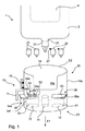
図1の図面を参照すると、ハウジング2が示され、これは、注射のための薬剤がその中に保持されるカートリッジ又はレセプタクル4を含む。カートリッジ4は、ハウジング2に取り外し可能に取り付けられ、例えば1日のように予め定められた期間の間、複数のインスリン用量の投薬のために特に適応することができる。作動した場合、用量は駆動機構及び用量機構によって制御される(図示されていない)。 Referring to the drawing of FIG. 1, a housing 2 is shown, which includes a cartridge or receptacle 4 in which medication for injection is held. The cartridge 4 is removably attached to the housing 2 and can be particularly adapted for the administration of multiple insulin doses for a predetermined period of time, for example one day. When activated, the dose is controlled by a drive mechanism and a dose mechanism (not shown).
ハウジング2は、針31を受け入れるための針取り付け部21を有する。図面中、針31には、注射する前に取り去らねばならない貯蔵用カバーが設けられる。
The housing 2 has a
図面の中で、それぞれ保護カバーを閉じるためのフィルム37を有する保護カバーを含む実施態様の中に、予備針アセンブリ32も、示されている。予備針を使用する前に、患者は、そのカバーから新しい針を取り出すためにフィルム37を取り去らなければならない。
A spare needle assembly 32 is also shown in the drawings, in an embodiment that includes a protective cover, each having a
更に図1において、軸方向、即ち、長手方向X1における第一の端部、即ち、遠位端E1、及び第二の端部、即ち、近位端E2を有する、本質的に円筒形状のキャップ10が示されている。キャップの第一の端部には、医薬品送達デバイス20のフロント部を受け入れるための開口部14が設けられ、それは針取り付け部を含む。第二の端部では、キャップ10は本質的に閉じられている。キャップ10の内部スペース又は内部10aにおいて、ハウジング2の針取り付け部21を受け入れるためにソケット11が設けられ、ここで、ソケット11は、針が取り付けられていない針取り付け部21及び/又は針31が取り付けられている針取り付け部21を受け入れるように設計される。ソケット11は、特に、針取り付け部21を受け入れることしかできないように設計することができ、それにより、使用者は、ハウジング2にキャップ10を取り付ける前に、それぞれの注射の後注射に使用された針31を除去するように強制される。
Further in FIG. 1, an essentially cylindrical cap having a first end in the axial direction, ie longitudinal direction X1, ie a distal end E1, and a second end, ie proximal end E2. 10 is shown. The first end of the cap is provided with an
キャップ10の内部スペース10aには第一のレセプタクル12が配列され、その中に予備針32又は予備針を含む箱を誘導することができる。第一のレセプタクルは、キャップ10の第一の端部、即ち、遠位端E1に位置する第一の端部、即ち、底部41、及び底部41からキャップ10の第二の端部、即ち、近位端E2に向かって伸びる距離をおいて第二の端部、即ち、近位端に位置する開口部42を有する。開口部42又はその上には、カバー36aを含んでなる開閉デバイス36が配列され、それは開位置及び閉位置の間を動くことができる。図1においては、カバー36aは閉位置にて示され、図2においては、カバー36aは開位置にて示されている。第一の閉鎖ユニットの開状態において、予備針は第一のレセプタクル12に導入することができ又はそこから除去され得る。開閉デバイス36は、使用者によってキャップ10の外側から操作される。
A
第一のレセプタクル12は、予備針32又は予備針を含む箱がレセプタクル12の中に所定の方向にのみ配向して収容できるように設計することができる。開口部42は、開口部14(図1〜3)に向かって配向することができ、又はキャップ10の遠位端E1に配置することができる。
The
或いは、又はこれに加えて、キャップ10の内部に、少なくとも1つの使用済み針33を受け入れるための又は保管するための第二のレセプタクル13を備えることができる。レセプタクル12は、特に、第二のレセプタクル13の開口部53に配列される被覆デバ
イス34a、及びそれによって被覆デバイス34aが、開口部53が少なくとも部分的に閉じられている第一の位置と開口部53が開いている第二の位置との間を可動の、開閉デバイス34を含む。開口部53は、キャップ10の遠位端E1から近位端E2に向かって距離をおいて配列される、レセプタクル13の端部に位置する。
Alternatively or in addition, a
被覆デバイス34aは、使用済み針33を第二のレセプタクル13に導入することはできるが、使用者が被覆デバイス34aを経由して第二のレセプタクルから除去することはできないように設計される。図1に示される実施例に記載の被覆デバイス34aは、2つの開口部34b、34cを含み、そのそれぞれはカバー34d、34eによって閉じられ、その両者は、使用済み針33を使用者が押し込むことができるように、そしてレセプタクル13に挿入された針33を使用者がそこから実質的に除去することができないように設計される。
The
図面に示される実施態様において、カバー34d、34eは、少なくとも2つのフラップ及びフラップの間で放射状に伸びるスロットを有する、円形の形状を有する。フラップは、使用者が使用済み針33をカバー34d、34eを通して押し込んだ場合、第二のレセプタクル13の内部に折り畳まれて入る。しかしながら、フラップは弾性材料で作られており、それらが反対側、即ち、第二のレセプタクルの外側に折り畳まれることはできないように設計され、その結果、一旦押し込まれてしまうと、使用済み針を第二のレセプタクル13から第二の閉鎖ユニット34を経由して引き出すことは不可能である。カバー34d、34eと共に被覆デバイス34aを開位置に動かすことによって、レセプタクルはレセプタクル13から針を除去するために開く。少なくとも1つのカバー34d、34eを有するそのような被覆デバイス34aは、代わりに、レセプタクルの遠位端51又は側壁34fに配列される開口部に配置することができる。
In the embodiment shown in the drawings, the
或いは、開口部とその上に伸びるカバーの少なくとも1つの組み合わせを有する被覆デバイス34aは、レセプタクル13の近位端に固定的に配置することができる。この実施態様においては、更なるカバー34gを、レセプタクル13の遠位端又は側壁34fに配置することができる(図3)。
Alternatively, the covering
図1及び2に示す実施態様において、ソケット11は、キャップ10の軸方向X1に沿って第一及び第二のレセプタクル12、13の間に配列される。
In the embodiment shown in FIGS. 1 and 2, the
開閉デバイス34は、操作エレメント71を用いてロック・デバイス70又はラッチ・デバイスによってロックすることができ、使用者によって操作することができる。ロック・デバイス70の1つの実施態様は、ロックされた状態で図1〜3に示されている。第二のレセプタクル13から排出するためには、キャップ10から遠ざかる方向にロック・デバイス70を引き出す必要がある。その結果、被覆デバイス34aを開位置に動かすことができ、使用済み針を第二のレセプタクル13から、例えば、重力によって除去され得る。ロック・デバイス70は、キャップ10の片側の部分に設けられる。安全のために、開口部及び閉鎖デバイス34を引出す前に、使用者はロックユニット35を非ロック位置に動かす必要がある。
The opening /
或いは、操作エレメント71は、キャップの側壁に案内デバイス75を配置することができ、それによって、操作エレメント71は、直線運動により開位置と閉位置との間を動くことができる。
Alternatively, the operating
例えば、レセプタクル12、13及び/又は開閉デバイス34及び/又は被覆デバイス34a及び/又はカバー36aは、特に互いに異なる色によって色付けすることができる。それにより、使用者は、レセプタクルのタイプを容易に確認することができる。また、開閉デバイス34及びロック・デバイス70は、同じ色によって色付けすることができる。
For example, the
本発明の上記の特徴又は実施態様は、部分的に又は全体として、如何なる方法によっても組み合わせることができる。 The above features or embodiments of the present invention can be combined in any way, in part or in whole.
Claims (12)
−医薬品送達デバイス(1)のフロント部(2)を受け入れるためのキャップ(10)の近位端(E2)におけるキャップ開口部(14);
−医薬品送達デバイス(1)の針取り付け部(21)を受け入れるためのソケット(11);
を含んでなるキャップ(10)であって、
−キャップ(10)の内部(10a)において、キャップ(10)の内部(10a)に少なくとも1つの予備針(32)を保管するように設計された少なくとも1つの第一のレセプタクル(12)が形成され、ここで、第一のレセプタクル(12)は、キャップ(10)の遠位端(E1)に位置する底部(41)、及び底部(41)からキャップ(10)の近位端(E2)に向かって伸びる距離に位置する第一のレセプタクルの開口部(42)を有し、
−第一の開閉デバイス(36)が第一のレセプタクル(12)の開口部(42)に配列され、第一の開閉デバイス(36)は、第一のレセプタクルの開口部(42)が閉じられる閉鎖位置及び第一のレセプタクルの開口部(42)が開かれる開放位置の間、そしてその逆の間を可動である第一の被覆デバイス(36a)を含んでなり、第一の開閉デバイス(36)は、その閉鎖位置にある場合は予備針(32)が第一のレセプタクル(12)内に保たれ、その開放位置にある場合は予備針(32)が第一のレセプタクルの開口部(42)を通して第一のレセプタクル(12)に挿入され得、そして第一のレセプタクルの開口部(42)を通して第一のレセプタクル(12)から除去され得るように設計されている、
ことを特徴とする、上記キャップ(10)。 A cap (10) for a portable pharmaceutical delivery device (1) comprising a needle for dispensing a pharmaceutical formulation in the distal direction, a front part for attaching the needle and a needle attachment part (21) at the distal end Having an axial direction (X1) defining (E1) and a proximal end (E2):
A cap opening (14) at the proximal end (E2) of the cap (10) for receiving the front part (2) of the drug delivery device (1);
A socket (11) for receiving the needle attachment (21) of the drug delivery device (1);
A cap (10) comprising:
In the interior (10a) of the cap (10), at least one first receptacle (12) designed to store at least one reserve needle (32) in the interior (10a) of the cap (10) is formed. Wherein the first receptacle (12) has a bottom (41) located at the distal end (E1) of the cap (10) and a proximal end (E2) of the cap (10) from the bottom (41). Having a first receptacle opening (42) located at a distance extending towards
The first opening / closing device (36) is arranged in the opening (42) of the first receptacle (12), the first opening / closing device (36) being closed in the opening (42) of the first receptacle; The first opening and closing device (36a) comprises a first covering device (36a) movable between a closed position and an open position where the opening (42) of the first receptacle is opened and vice versa. ) Is kept in the first receptacle (12) when in its closed position, while the spare needle (32) is in the opening (42 ) of the first receptacle when in its open position. ) And can be inserted into the first receptacle (12 ) through the first receptacle opening (42 ) and removed from the first receptacle (12).
The cap (10), characterized in that.
3)は、第二のレセプタクル(13)の開口部(53)に配列され、カバー開口部(34b,34c)を被覆するように適合された少なくとも1個のカバー(34d,34e)を備え、第二のレセプタクル(13)の開口部(53)が少なくとも部分的に被覆される第一の位置及び第二のレセプタクル(13)の開口部(53)が開かれる第二の位置の間を、第二の開閉デバイス(34)によって可動である第二の被覆デバイス(34a)を含んでなる、請求項1に記載のキャップ(10)。 The interior (10a) of the cap (10) comprises a second receptacle (13) designed to store at least one used needle (33), the second receptacle (1)
3) comprises at least one cover (34d, 34e) arranged in the opening (53) of the second receptacle (13) and adapted to cover the cover opening (34b, 34c); Between a first position where the opening (53) of the second receptacle (13) is at least partially covered and a second position where the opening (53) of the second receptacle (13) is opened, The cap (10) according to claim 1, comprising a second covering device (34a) movable by a second opening and closing device (34).
ャップ(10)によって被覆され得ることを特徴とする、上記医薬品送達デバイス(1)。 A needle mounting portion ( 21 ) for mounting the needle (31) on the housing (2), and a medicine to be delivered via the needle (31) when mounted on the needle mounting portion (21). A drug delivery device (1) comprising a housing (2) having a drug receptacle (4) of claim 1, wherein the needle attachment ( 21 ) is a cap (10) according to any one of claims 1 to 11. Said pharmaceutical delivery device (1), characterized in that it can be coated by:
Applications Claiming Priority (3)
| Application Number | Priority Date | Filing Date | Title |
|---|---|---|---|
| EP09008851.9 | 2009-08-12 | ||
| EP09008851 | 2009-08-12 | ||
| PCT/EP2010/061421 WO2011018408A1 (en) | 2009-08-12 | 2010-08-05 | Cap for a portable medical delivery device and such a medical delivery device |
Publications (3)
| Publication Number | Publication Date |
|---|---|
| JP2013501554A JP2013501554A (en) | 2013-01-17 |
| JP2013501554A5 JP2013501554A5 (en) | 2013-09-12 |
| JP5865835B2 true JP5865835B2 (en) | 2016-02-17 |
Family
ID=42469626
Family Applications (1)
| Application Number | Title | Priority Date | Filing Date |
|---|---|---|---|
| JP2012524204A Expired - Fee Related JP5865835B2 (en) | 2009-08-12 | 2010-08-05 | Cap for portable drug delivery device and such drug delivery device |
Country Status (6)
| Country | Link |
|---|---|
| US (1) | US20120197208A1 (en) |
| EP (1) | EP2464400B1 (en) |
| JP (1) | JP5865835B2 (en) |
| CA (1) | CA2770558A1 (en) |
| DK (1) | DK2464400T3 (en) |
| WO (1) | WO2011018408A1 (en) |
Families Citing this family (24)
| Publication number | Priority date | Publication date | Assignee | Title |
|---|---|---|---|---|
| US20070202186A1 (en) | 2006-02-22 | 2007-08-30 | Iscience Interventional Corporation | Apparatus and formulations for suprachoroidal drug delivery |
| US8197435B2 (en) | 2006-05-02 | 2012-06-12 | Emory University | Methods and devices for drug delivery to ocular tissue using microneedle |
| EP2506897B1 (en) | 2009-12-04 | 2023-05-31 | Becton, Dickinson and Company | Pen needle removal device for a drug delivery device |
| WO2012051575A2 (en) | 2010-10-15 | 2012-04-19 | Iscience Interventional Corporation | Device for ocular access |
| AU2012335825B2 (en) | 2011-11-07 | 2017-02-16 | Safety Syringes, Inc. | Contact trigger release needle guard |
| GB2497735A (en) * | 2011-12-16 | 2013-06-26 | Owen Mumford Ltd | Needle Tip Storage and Removal Device |
| US20150258120A1 (en) | 2012-11-08 | 2015-09-17 | Clearside Biomedical, Inc. | Methods and devices for the treatment of ocular diseases in human subjects |
| CN105050639B (en) * | 2013-03-15 | 2019-08-02 | 希普罗特克有限公司 | Multi-chamber injection device |
| SG10201702674PA (en) | 2013-05-03 | 2017-06-29 | Clearside Biomedical Inc | Apparatus and methods for ocular injection |
| EP3003454B1 (en) | 2013-06-03 | 2020-01-08 | Clearside Biomedical, Inc. | Apparatus for drug delivery using multiple reservoirs |
| WO2015196085A2 (en) | 2014-06-20 | 2015-12-23 | Clearside Biomedical, Inc. | Variable diameter cannula and methods for controlling insertion depth for medicament delivery |
| USD750223S1 (en) | 2014-10-14 | 2016-02-23 | Clearside Biomedical, Inc. | Medical injector for ocular injection |
| US10390901B2 (en) | 2016-02-10 | 2019-08-27 | Clearside Biomedical, Inc. | Ocular injection kit, packaging, and methods of use |
| USD819198S1 (en) | 2016-04-28 | 2018-05-29 | Amgen Inc. | Autoinjector with removable cap |
| JP2019514581A (en) | 2016-05-02 | 2019-06-06 | クリアサイド バイオメディカル,インコーポレイテッド | Systems and methods for ocular drug delivery |
| CN110177527B (en) | 2016-08-12 | 2022-02-01 | 科尼尔赛德生物医学公司 | Device and method for adjusting insertion depth of needle for medicament delivery |
| USD1010811S1 (en) | 2019-09-30 | 2024-01-09 | Amgen Inc. | Handheld drug delivery device |
| USD974547S1 (en) | 2020-11-05 | 2023-01-03 | Amgen Inc. | Handheld drug delivery device |
| USD962423S1 (en) | 2020-11-05 | 2022-08-30 | Amgen Inc. | Handheld drug delivery device |
| USD973866S1 (en) | 2020-11-05 | 2022-12-27 | Amgen Inc. | Handheld drug delivery device |
| USD985117S1 (en) | 2021-03-10 | 2023-05-02 | Amgen Inc. | Handheld drug delivery device |
| USD985116S1 (en) | 2021-03-10 | 2023-05-02 | Amgen Inc. | Handheld drug delivery device |
| USD985118S1 (en) | 2021-03-10 | 2023-05-02 | Amgen Inc. | Handheld drug delivery device |
| USD985119S1 (en) | 2021-03-30 | 2023-05-02 | Amgen Inc. | Handheld drug delivery device |
Family Cites Families (20)
| Publication number | Priority date | Publication date | Assignee | Title |
|---|---|---|---|---|
| US4410086A (en) * | 1982-03-05 | 1983-10-18 | Simpson James L | Medical appliance disposal container |
| US5285896A (en) * | 1992-03-25 | 1994-02-15 | Timely Medical Innovations, Ltd. | Apparatus for receiving and capturing a hypodermic needle hub and cannula |
| US5265724A (en) * | 1992-05-06 | 1993-11-30 | Dondlinger Steven C | Medical needle disposal package |
| US5832971A (en) * | 1994-05-19 | 1998-11-10 | Becton, Dickinson And Company | Syringe filling and delivery device |
| CN1145501C (en) | 1996-09-13 | 2004-04-14 | 诺沃挪第克公司 | Syringe |
| DE19717033A1 (en) * | 1997-04-23 | 1998-11-12 | Schott Glas | Needle cap for a prefillable disposable syringe |
| US5829589A (en) * | 1997-09-12 | 1998-11-03 | Becton Dickinson And Company | Pen needle magazine dispenser |
| DE19856167C1 (en) * | 1998-12-05 | 2000-05-04 | Vetter & Co Apotheker | Needle protection for e.g. syringes includes protective casing inside protective cap which remains in place during self-injection, to help assure hygiene and to hide the needle |
| SE9904783D0 (en) * | 1999-12-22 | 1999-12-22 | Gambro Lundia Ab | Needle holding device |
| US6279743B1 (en) * | 2000-04-11 | 2001-08-28 | Cambridge Marketing, Inc. | Device for facilitating engagement and disengagement between needles and associated syringes and sheaths and for receiving sharps |
| EA003971B1 (en) * | 2000-05-15 | 2003-12-25 | Арес Трейдинг С.А. | Storage container for at least one hypodermic needle |
| AU2001285239A1 (en) * | 2000-09-19 | 2002-04-02 | Kendell Simm | Hypodermic needle holder |
| US20030015444A1 (en) * | 2001-06-11 | 2003-01-23 | Anders Molin | Needle magazine |
| DE10316127A1 (en) * | 2003-04-09 | 2004-11-04 | Arzneimittel Gmbh Apotheker Vetter & Co. Ravensburg | Pre-filled syringe or cartridge for medical purposes |
| FR2876034A1 (en) * | 2003-11-14 | 2006-04-07 | Plastic Omnium Cie | Injection syringe safety assembly has attachment on end of syringe barrel that holds piston inside it |
| US20110098656A1 (en) * | 2005-09-27 | 2011-04-28 | Burnell Rosie L | Auto-injection device with needle protecting cap having outer and inner sleeves |
| JP4195900B2 (en) * | 2005-12-14 | 2008-12-17 | 株式会社スズケン | Needle cartridge and syringe |
| GB2438593B (en) * | 2006-06-01 | 2011-03-30 | Cilag Gmbh Int | Injection device (cap removal feature) |
| US7780637B2 (en) | 2006-11-06 | 2010-08-24 | Steven Jerde | Medical device container |
| WO2009016161A1 (en) * | 2007-07-28 | 2009-02-05 | Novo Nordisk A/S | A needle magazine |
-
2010
- 2010-08-05 US US13/388,646 patent/US20120197208A1/en not_active Abandoned
- 2010-08-05 CA CA2770558A patent/CA2770558A1/en not_active Abandoned
- 2010-08-05 WO PCT/EP2010/061421 patent/WO2011018408A1/en active Application Filing
- 2010-08-05 DK DK10740637.3T patent/DK2464400T3/en active
- 2010-08-05 JP JP2012524204A patent/JP5865835B2/en not_active Expired - Fee Related
- 2010-08-05 EP EP10740637.3A patent/EP2464400B1/en not_active Not-in-force
Also Published As
| Publication number | Publication date |
|---|---|
| JP2013501554A (en) | 2013-01-17 |
| US20120197208A1 (en) | 2012-08-02 |
| DK2464400T3 (en) | 2015-05-04 |
| WO2011018408A1 (en) | 2011-02-17 |
| EP2464400B1 (en) | 2015-01-28 |
| EP2464400A1 (en) | 2012-06-20 |
| CA2770558A1 (en) | 2011-02-17 |
Similar Documents
| Publication | Publication Date | Title |
|---|---|---|
| JP5865835B2 (en) | Cap for portable drug delivery device and such drug delivery device | |
| US11786670B2 (en) | Pen needle removal device for a drug delivery device | |
| US20190038837A1 (en) | Drive Control Mechanisms And Automatic Injectors For Injectable Cartridges | |
| US10799650B2 (en) | Disposable pen needle with re-use prevention features | |
| JP4448448B2 (en) | Injection device | |
| JP6001244B2 (en) | Living hinged needle assembly for a drug delivery device | |
| EP2420266B1 (en) | Attachable needle changing device for medicament delivery device | |
| EP2337599B1 (en) | Container for injection device with injection needle | |
| EP2298224B1 (en) | Shipping container integrating a sharps disposal container with a new product storage container | |
| EP3628350B1 (en) | Syringe assembly having a flexible or slidable flange | |
| BR112014005489B1 (en) | rechargeable autoinjector and method for operating a rechargeable autoinjector | |
| US10695493B2 (en) | Pen-type injector | |
| WO2022090981A1 (en) | Device for injecting fluid in a body | |
| WO2014072499A1 (en) | Drug delivery device with integrated shield | |
| CZ20004892A3 (en) | Medication delivery device and a cartridge assembly for use in the same |
Legal Events
| Date | Code | Title | Description |
|---|---|---|---|
| A521 | Written amendment |
Free format text: JAPANESE INTERMEDIATE CODE: A523 Effective date: 20130730 |
|
| A621 | Written request for application examination |
Free format text: JAPANESE INTERMEDIATE CODE: A621 Effective date: 20130730 |
|
| A131 | Notification of reasons for refusal |
Free format text: JAPANESE INTERMEDIATE CODE: A131 Effective date: 20140520 |
|
| A977 | Report on retrieval |
Free format text: JAPANESE INTERMEDIATE CODE: A971007 Effective date: 20140523 |
|
| A601 | Written request for extension of time |
Free format text: JAPANESE INTERMEDIATE CODE: A601 Effective date: 20140819 |
|
| A602 | Written permission of extension of time |
Free format text: JAPANESE INTERMEDIATE CODE: A602 Effective date: 20140826 |
|
| A601 | Written request for extension of time |
Free format text: JAPANESE INTERMEDIATE CODE: A601 Effective date: 20140919 |
|
| A602 | Written permission of extension of time |
Free format text: JAPANESE INTERMEDIATE CODE: A602 Effective date: 20140929 |
|
| A521 | Written amendment |
Free format text: JAPANESE INTERMEDIATE CODE: A523 Effective date: 20141017 |
|
| A02 | Decision of refusal |
Free format text: JAPANESE INTERMEDIATE CODE: A02 Effective date: 20150331 |
|
| A521 | Written amendment |
Free format text: JAPANESE INTERMEDIATE CODE: A523 Effective date: 20150731 |
|
| A911 | Transfer of reconsideration by examiner before appeal (zenchi) |
Free format text: JAPANESE INTERMEDIATE CODE: A911 Effective date: 20150929 |
|
| TRDD | Decision of grant or rejection written | ||
| A01 | Written decision to grant a patent or to grant a registration (utility model) |
Free format text: JAPANESE INTERMEDIATE CODE: A01 Effective date: 20151201 |
|
| A61 | First payment of annual fees (during grant procedure) |
Free format text: JAPANESE INTERMEDIATE CODE: A61 Effective date: 20151228 |
|
| R150 | Certificate of patent or registration of utility model |
Ref document number: 5865835 Country of ref document: JP Free format text: JAPANESE INTERMEDIATE CODE: R150 |
|
| LAPS | Cancellation because of no payment of annual fees |