JP5861455B2 - Antenna device - Google Patents
Antenna device Download PDFInfo
- Publication number
- JP5861455B2 JP5861455B2 JP2011289197A JP2011289197A JP5861455B2 JP 5861455 B2 JP5861455 B2 JP 5861455B2 JP 2011289197 A JP2011289197 A JP 2011289197A JP 2011289197 A JP2011289197 A JP 2011289197A JP 5861455 B2 JP5861455 B2 JP 5861455B2
- Authority
- JP
- Japan
- Prior art keywords
- antenna
- ground
- antenna element
- vehicle
- coaxial line
- Prior art date
- Legal status (The legal status is an assumption and is not a legal conclusion. Google has not performed a legal analysis and makes no representation as to the accuracy of the status listed.)
- Active
Links
Images


Classifications
-
- H—ELECTRICITY
- H01—ELECTRIC ELEMENTS
- H01Q—ANTENNAS, i.e. RADIO AERIALS
- H01Q1/00—Details of, or arrangements associated with, antennas
- H01Q1/27—Adaptation for use in or on movable bodies
- H01Q1/32—Adaptation for use in or on road or rail vehicles
-
- H—ELECTRICITY
- H01—ELECTRIC ELEMENTS
- H01Q—ANTENNAS, i.e. RADIO AERIALS
- H01Q1/00—Details of, or arrangements associated with, antennas
- H01Q1/08—Means for collapsing antennas or parts thereof
- H01Q1/084—Pivotable antennas
-
- H—ELECTRICITY
- H01—ELECTRIC ELEMENTS
- H01Q—ANTENNAS, i.e. RADIO AERIALS
- H01Q1/00—Details of, or arrangements associated with, antennas
- H01Q1/12—Supports; Mounting means
- H01Q1/1271—Supports; Mounting means for mounting on windscreens
-
- H—ELECTRICITY
- H01—ELECTRIC ELEMENTS
- H01Q—ANTENNAS, i.e. RADIO AERIALS
- H01Q1/00—Details of, or arrangements associated with, antennas
- H01Q1/27—Adaptation for use in or on movable bodies
- H01Q1/32—Adaptation for use in or on road or rail vehicles
- H01Q1/3208—Adaptation for use in or on road or rail vehicles characterised by the application wherein the antenna is used
- H01Q1/3233—Adaptation for use in or on road or rail vehicles characterised by the application wherein the antenna is used particular used as part of a sensor or in a security system, e.g. for automotive radar, navigation systems
-
- H—ELECTRICITY
- H01—ELECTRIC ELEMENTS
- H01Q—ANTENNAS, i.e. RADIO AERIALS
- H01Q1/00—Details of, or arrangements associated with, antennas
- H01Q1/27—Adaptation for use in or on movable bodies
- H01Q1/32—Adaptation for use in or on road or rail vehicles
- H01Q1/325—Adaptation for use in or on road or rail vehicles characterised by the location of the antenna on the vehicle
- H01Q1/3291—Adaptation for use in or on road or rail vehicles characterised by the location of the antenna on the vehicle mounted in or on other locations inside the vehicle or vehicle body
-
- H—ELECTRICITY
- H01—ELECTRIC ELEMENTS
- H01Q—ANTENNAS, i.e. RADIO AERIALS
- H01Q1/00—Details of, or arrangements associated with, antennas
- H01Q1/48—Earthing means; Earth screens; Counterpoises
-
- H—ELECTRICITY
- H01—ELECTRIC ELEMENTS
- H01Q—ANTENNAS, i.e. RADIO AERIALS
- H01Q1/00—Details of, or arrangements associated with, antennas
- H01Q1/50—Structural association of antennas with earthing switches, lead-in devices or lightning protectors
-
- H—ELECTRICITY
- H01—ELECTRIC ELEMENTS
- H01Q—ANTENNAS, i.e. RADIO AERIALS
- H01Q1/00—Details of, or arrangements associated with, antennas
- H01Q1/52—Means for reducing coupling between antennas; Means for reducing coupling between an antenna and another structure
-
- H—ELECTRICITY
- H01—ELECTRIC ELEMENTS
- H01Q—ANTENNAS, i.e. RADIO AERIALS
- H01Q5/00—Arrangements for simultaneous operation of antennas on two or more different wavebands, e.g. dual-band or multi-band arrangements
- H01Q5/40—Imbricated or interleaved structures; Combined or electromagnetically coupled arrangements, e.g. comprising two or more non-connected fed radiating elements
-
- H—ELECTRICITY
- H01—ELECTRIC ELEMENTS
- H01Q—ANTENNAS, i.e. RADIO AERIALS
- H01Q9/00—Electrically-short antennas having dimensions not more than twice the operating wavelength and consisting of conductive active radiating elements
- H01Q9/04—Resonant antennas
- H01Q9/30—Resonant antennas with feed to end of elongated active element, e.g. unipole
- H01Q9/32—Vertical arrangement of element
- H01Q9/38—Vertical arrangement of element with counterpoise
Description
本開示は、車などの移動体において放送信号を受信するのに好適なアンテナ装置に関する。 The present disclosure relates to an antenna device suitable for receiving a broadcast signal in a moving body such as a car.
従来、車に備え付けのカーナビゲーション装置や、車に取り付けたPND(Personal Navigation Device)のアンテナとしては、車外に取り付けるロッドアンテナか、フロントガラスまたはリアガラスに貼付可能なフィルムアンテナが用いられることが多い。 Conventionally, as a car navigation device installed in a car or an antenna of a PND (Personal Navigation Device) attached to a car, a rod antenna attached outside the car or a film antenna that can be attached to a windshield or rear glass is often used.
車のような移動体で放送を受信する場合には、フェージングの影響を受けて受信信号の信号レベルが大きく変動してしまうため、フェージングの影響による受信信号の劣化を補う目的で、ダイバーシティ受信が行われることが多い。しかし、ダイバーシティ受信を行うには、アンテナを複数本設ける必要がある。 When receiving a broadcast by a mobile body such as a car, the signal level of the received signal fluctuates greatly due to the influence of fading, so diversity reception is performed for the purpose of compensating for the deterioration of the received signal due to the influence of fading. Often done. However, in order to perform diversity reception, it is necessary to provide a plurality of antennas.
このため、ダイバーシティ受信を行うためのアンテナとしては、本数が増えることで見栄えが悪くなってしまうロッドアンテナよりも、見栄えにほぼ影響しないフィルムアンテナが選択されることが多い。 Therefore, as an antenna for performing diversity reception, a film antenna that does not substantially affect the appearance is often selected rather than a rod antenna that deteriorates in appearance as the number increases.
例えば、特許文献1には、車両の前後左右の4面にフィルムアンテナを設置することにより、放送波を安定的に受信できるようにする技術が記載されている。 For example, Patent Document 1 describes a technology that enables broadcast waves to be stably received by installing film antennas on four front, rear, left, and right surfaces of a vehicle.
ところが、フィルムアンテナは窓への取り付けが難しいため、適切な位置に綺麗に貼り付けるには、ユーザは、専門の業者に作業を依頼して取り付けを行ってもらう必要があった。このようなケースでは、ユーザは、フィルムアンテナの代金に加えて別途作業の工賃を支払う必要があった。 However, since it is difficult to attach the film antenna to the window, the user needs to ask an expert to perform the installation in order to attach the film antenna in an appropriate position. In such a case, the user has to pay a separate labor cost in addition to the price of the film antenna.
また、フィルムアンテナは、アンテナエレメントとして導電率がよいとは言えない部材を使用していることと、アンテナケーブルの長さが長いことにより、そのアンテナのゲインは、ロッドアンテナ等と比較して低いものとなっている。この問題を解決するために、多くのフィルムアンテナではアンプが併用されている。しかし、アンプを設けることにより、消費電力が増加したり、専用のコネクタが必要となったりするという問題も生じてしまう。 Further, the film antenna uses a member that cannot be said to have good conductivity as the antenna element, and the antenna cable has a long length, so that the gain of the antenna is lower than that of a rod antenna or the like. It has become a thing. In order to solve this problem, an amplifier is used in combination with many film antennas. However, the provision of an amplifier also causes problems such as increased power consumption and the need for a dedicated connector.
本開示は、受信性能がよく、かつ取り付けが容易なアンテナ装置を提供することを目的とする。 An object of the present disclosure is to provide an antenna device that has good reception performance and is easy to install.
本開示のアンテナ装置は、放送波および前記放送波に重畳して伝送された信号を受信するアンテナエレメントと、所定の長さを有し、アンテナエレメントとの相対角度を調整可能に構成したグランドエレメントとを備える。そして、グランドエレメントとアンテナエレメントとの相対位置関係に応じて、グランドエレメントと、当該アンテナ装置が設置される車の車体の金属部分との間で発生する容量結合の結合容量の大きさが変化する。 An antenna device of the present disclosure includes an antenna element that receives a broadcast wave and a signal transmitted by being superimposed on the broadcast wave, and a ground element that has a predetermined length and is configured to be capable of adjusting a relative angle with the antenna element. With. Then, according to the relative positional relationship between the ground element and the antenna element, the magnitude of the coupling capacity of the capacitive coupling generated between the ground element and the metal part of the vehicle body of the vehicle where the antenna device is installed changes. .
このように構成したことで、グランドエレメントのアンテナエレメントに対する角度を調整することにより、グランドエレメントと、当該車載アンテナを搭載した車体の金属部分との間で容量結合が起きる。これにより、放送信号を受信するアンテナ装置のグランドとして機能する部分の面積が拡大するため、アンテナ装置の受信特性が向上する。また、アンテナエレメントとグランドエレメントとを、例えば車体のダッシュボード上等に配置するだけでアンテナ装置が形成されるため、その取り付けも非常に容易に行うことができる。 With this configuration, by adjusting the angle of the ground element with respect to the antenna element, capacitive coupling occurs between the ground element and the metal part of the vehicle body on which the vehicle-mounted antenna is mounted. As a result, the area of the portion that functions as the ground of the antenna device that receives the broadcast signal is increased, and the reception characteristics of the antenna device are improved. Further, since the antenna device is formed simply by arranging the antenna element and the ground element on, for example, the dashboard of the vehicle body, the attachment thereof can be performed very easily.
本開示によれば、受信性能がよく、かつ取り付けが容易なアンテナ装置が提供される。 According to the present disclosure, an antenna device that has good reception performance and is easy to install is provided.
以下、本開示を実施するための形態について説明する。なお、説明は以下の順序で行う。
1.第1の実施の形態例(アンテナエレメントとグランドエレメントとを基板を介して接続した例)
2.第1の実施の形態の変形例
2−1.第1の実施の形態の変形例1(アンテナエレメントを基板で構成した例)
2−2.第1の実施の形態の変形例2(アンテナエレメントを基板で構成し、グランドエレメントとは異なるグランド部とアンテナエレメントとでJ型アンテナを構成した例)
2−3.第1の実施の形態の変形例3(アンテナエレメントを複数設けて、グランドエレメントとの接続部を共有する例)
3.第2の実施の形態例(グランドエレメントを棒状アンテナで構成した例)
3−1.第2の実施の形態の変形例(棒状アンテナで構成したグランドエレメントを複数設けた例)
4.各種変形例
Hereinafter, modes for carrying out the present disclosure will be described. The description will be given in the following order.
1. First embodiment (an example in which an antenna element and a ground element are connected via a substrate)
2. 2. Modification of first embodiment 2-1. Modification 1 of the first embodiment (example in which the antenna element is configured by a substrate)
2-2. Modification 2 of the first embodiment (example in which the antenna element is configured by a substrate and a J-type antenna is configured by a ground portion and an antenna element different from the ground element)
2-3. Modification 3 of the first embodiment (an example in which a plurality of antenna elements are provided and a connection portion with a ground element is shared)
3. Second embodiment (example in which the ground element is constituted by a rod-shaped antenna)
3-1. Modified example of the second embodiment (example in which a plurality of ground elements constituted by rod antennas are provided)
4). Various modifications
<1.第1の実施の形態例>
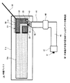
図1は、本開示の第1の実施の形態による車載アンテナの構成例を示す概略図である。図1に示す車載アンテナ1は、アンテナエレメント10と、高周波伝送線路20と、グランドエレメント30と、アンテナケーブルとしての同軸線40とを含む。本実施の形態では、アンテナエレメント10を金属のロッド等の導電性の線材で構成しており、アンテナエレメント10を、グランド付きコプレーナラインで構成した高周波伝送線路20の、信号パターン(信号線路)21に接続させている。コプレーナラインとは、信号線路と接地導体とが同一平面上に存在する伝送線路である。
<1. First Embodiment>
FIG. 1 is a schematic diagram illustrating a configuration example of an in-vehicle antenna according to the first embodiment of the present disclosure. The in-vehicle antenna 1 shown in FIG. 1 includes an
高周波伝送線路20には、上述したようにグランド付きコプレーナラインを使用しており、平板状の誘電体よりなる基板21の表面上に、直接または絶縁膜を介して信号パターン22とグランド導体23(接地導体)とが設けられている。信号パターン22とグランド導体23との間は、線状の空隙部であるスリット24が適切な幅をもって設けられている。グランド導体23は、基板21の裏面にも形成されており、上面のグランド導体23とは、通常スルーホール等により接続され、グランドとして機能するように構成されている。高周波伝送線路20をグランド付きコプレーナラインで構成することにより、基板による誘電体損失が低く抑えられるため、アンテナエレメント10で受信した高周波信号を減衰させることなく通過させることができる。
As described above, the coplanar line with a ground is used for the high-
基板21上のグランド導体23には、金属のロッド等の導電性の線材で構成したグランドエレメント30を接続させている。このように構成することで、アンテナエレメント10とグランドエレメント30とによってアンテナが構成される。アンテナエレメント10の長さとグランドエレメント30の長さとを足した全体の長さを、受信したい周波数の約λ/2とすることで、車載アンテナ1で所望の周波数を受信できるようになる。実際には、アンテナエレメント10の材料及びグランドエレメント30の材料や、受信周波数により、エレメントの調整は適宜行う必要がある。本実施の形態では、例えばアンテナエレメント10を13cm、グランドエレメント30を10cmとすることで、UHF帯の周波数を受信できるように構成している。
A
基板21上の信号パターン22の、アンテナエレメント10が接続された側とは反対側の端部には、同軸線40の芯線41を接続させてあり、グランド導体23の端部には、同軸線40の外部導体43を接続させてある。つまり、同軸線40は、その先端部分において保護被覆44および外部導体43を取り除いてあり、誘導体42と芯線41とが露出された状態としてある。また、本実施の形態による車載アンテナ1の給電点Fpは、グランド導体23に対してアンテナエレメント10が図中の左側の方向に飛び出した部分となる。すなわち、アンテナエレメント10と信号パターン22とが接続された部分に給電点Fpが形成される。
The
アンテナエレメント10とグランドエレメント30と同軸線40とが、高周波伝送線路20に接続された部分である接続部50は、エラストマー等の樹脂51によりモールド成形されている。つまり、樹脂51が基板21や信号パターン22、グランド導体23を覆うように形成されている。同軸線40の、接続部50に接続された側とは反対側の端部には、同軸コネクタ45が取り付けられている。
A
また、同軸線40の途中には、高周波減衰部材としてのフェライトコア60を設けてある。フェライトコア60を設けることにより、フェライトコア60から同軸コネクタ45までの間の同軸線40の保護被覆44には電波が載らなくなる。これにより、アンテナエレメント10が受けたイメージ電流やノイズは、接続部50からフェライトコア60までの間の保護被覆44に流れるようになる。つまり、この部分がアンテナエレメント10のグランドとして機能するようになる。これにより、同軸線40の保護被覆44がアンテナとなって意図しない周波数の電波が誘起されてしまうことを防ぐことができる。
A
また、アンテナのグランドとして機能する部分が広くなることで、アンテナエレメント10の受信特性が向上する。フェライトコア60を設ける同軸線40上の位置(接続部50との距離)は、受信したい周波数等に合わせて任意の位置に調整できるものとする。本実施の形態では、フェライトコア60を、接続部50から7cm離れた位置に設けることにより、アンテナエレメント10に乗ったノイズやイメージ電流をもっとも良く取り除くことができた。
In addition, since the portion that functions as the ground of the antenna is widened, the reception characteristics of the
また、上述したように、車載アンテナ1の給電点Fpは基板21の信号パターン22とアンテナエレメント10とが接続された位置に構成される。この給電点Fpのインピーダンスを、フェライトコア60の挿入位置やアンテナエレメント10の長さにより調整することで、受信周波数を決定することが可能となる。
Further, as described above, the feeding point Fp of the in-vehicle antenna 1 is configured at a position where the
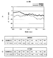
図2に、図1に示した車載アンテナ1でUHF帯の放送を受信したときの周波数−ゲイン特性を示す。図1に示した同軸線40は、長さが3mのものを使用した。図2Aはグラフであり、図2Bおよび図2Cにデータを示している。図2Aの横軸は周波数(MHz)を示し、縦軸はピークゲイン(dBd)を示す。グラフ中の実線は水平偏波受信時のゲイン特性を示し、破線は垂直偏波受信時のゲイン特性を示している。図2Bは垂直偏波受信時の周波数−ゲイン特性を示すデータであり、図2Cは水平偏波受信時の周波数−ゲイン特性を示すデータである。図2A〜図2Cに示すように、470MHz〜870MHzのUHF帯では、テレビ放送の主偏波である水平偏波において、概ね−10dB以上のゲイン特性が得られていることが確認できた。
FIG. 2 shows frequency-gain characteristics when the in-vehicle antenna 1 shown in FIG. 1 receives a UHF band broadcast. The
図3には、復調前の受信信号におけるC/N比(Carrier to Noise Ratio)を、従来のフィルムアンテナにおけるものとの比較で示している。図3Aは、車載アンテナ1でUHF帯の信号(中心周波数475MHz)を受信した場合における受信信号のC/N比を示すグラフであり、図3Bは、従来のフィルムアンテナでUHF帯の信号を受信した場合における受信信号のC/N比を示すグラフである。従来のフィルムアンテナとしては、受信信号のレベルを15dBアップさせるアンプを用いたものを使用した。図3Aおよび図3Bにおいて、横軸は周波数(MHz)を示し、縦軸は信号レベル(dBm)を示す。
FIG. 3 shows a C / N ratio (Carrier to Noise Ratio) in a received signal before demodulation in comparison with that in a conventional film antenna. FIG. 3A is a graph showing a C / N ratio of a received signal when a vehicle-mounted antenna 1 receives a UHF band signal (
図3Aに示すように、本実施の形態による車載アンテナ1が受信した信号においては、ノイズフロアは破線で示したように−122dBm近辺の値であり、信号レベルは一点鎖線で示したように−105dBm近辺の値となっている。これに対して、従来のフィルムアンテナで受信した信号においては、図3Bに示すように、信号のレベルが−88dBm近辺まで上がっている。しかし、信号レベルとともに、ノイズフロアも−108dBm近辺まで上がっていることが分かる。つまり、図3Bにおいて、ノイズフロアのレベルを示す一点鎖線と信号レベルを示す破線との間隔で示されるC/N比は、図3Aに示した車載アンテナ1におけるC/N比とさほど変わっていない。周波数によっては、むしろ図3Aに示した車載アンテナ1におけるC/N比の方が若干よくなっている。 As shown in FIG. 3A, in the signal received by the vehicle-mounted antenna 1 according to the present embodiment, the noise floor is a value around −122 dBm as shown by a broken line, and the signal level is shown as a one-dot chain line − The value is around 105 dBm. On the other hand, in the signal received by the conventional film antenna, as shown in FIG. 3B, the level of the signal rises to around −88 dBm. However, it can be seen that with the signal level, the noise floor also rises to around -108 dBm. That is, in FIG. 3B, the C / N ratio indicated by the distance between the alternate long and short dash line indicating the noise floor level and the broken line indicating the signal level is not much different from the C / N ratio in the in-vehicle antenna 1 shown in FIG. 3A. . Rather, the C / N ratio in the in-vehicle antenna 1 shown in FIG. 3A is slightly better depending on the frequency.
図4は、車載アンテナ1の車体への配置例を示す概略図である。車載アンテナ1で例えばフルセグメント放送等の高次の変調方式が用いられた放送を受信する場合には、車載アンテナ1を2本設けてダイバーシティ受信することで、アンテナの受信特性を向上させることができる。図4には、2本の車載アンテナ1を、車のフロントガラス101の下辺と接するダッシュボード102の右端と左端にそれぞれ配置した例を示してある。左右の車載アンテナ1において、アンテナエレメント10はダッシュボード102上で、フロントガラス101の下辺に対して平行になるようにまっすぐ伸ばしてあり、グランドエレメント30は、フロントガラス101の左右の辺に沿うように這わせてある。
FIG. 4 is a schematic diagram showing an example of arrangement of the vehicle-mounted antenna 1 on the vehicle body. For example, when receiving an in-vehicle antenna 1 that uses a high-order modulation method such as full-segment broadcasting, it is possible to improve the antenna reception characteristics by providing two in-vehicle antennas 1 for diversity reception. it can. FIG. 4 shows an example in which two in-vehicle antennas 1 are arranged at the right end and the left end of the dashboard 102 in contact with the lower side of the car windshield 101. In the left and right vehicle-mounted antennas 1, the
左右の車載アンテナ1の各同軸線40の先端部分に設けられた同軸コネクタ45は、PND200に取り付けてある。PND200の内部には受信機210が構成されており、この受信機210がダイバーシティ受信を行って受信信号を復調する。本実施の形態では、ダイバーシティ受信として、例えば空間ダイバーシティの最大比合成方式を用いている。受信機210によって復調された信号は、液晶ディスプレイ等よりなる表示部220の画面上に表示される。
A
車載アンテナ1をこのように配置することで、フロントガラス101の端にある車の金属ボディと、車載アンテナ1のグランドエレメント30とが容量結合して、アンテナのグランドが広くなる。これにより、車載アンテナ1での受信信号のレベルが向上し、さらには、走行時の受信特性も改善する。
By disposing the in-vehicle antenna 1 in this manner, the metal body of the car at the end of the windshield 101 and the
本実施の形態の車載アンテナ1によれば、グランドエレメント30と車体の金属部分とが容量結合することによりアンテナのグランドとして機能する部分が拡大するため、従来のフィルムアンテナと同等またはそれ以上の受信特性を得ることが可能となる。また、アンテナをフロントガラス101やリアガラス(図示略)に貼り付ける必要がないため、アンテナエレメント10の素材として、導電性のよい金属の部材を使用することができるようになる。さらに、フロントガラス101の上端や図示せぬリアガラス等の、カーナビゲーション装置やPND200から離れた位置にアンテナを配置する必要がなくなるため、アンテナケーブル(同軸線40)長も短くすることができる。
According to the vehicle-mounted antenna 1 of the present embodiment, the portion that functions as the ground of the antenna is expanded by capacitively coupling the
したがって、アンテナエレメントの材質やケーブル長の長さに起因して落ちてしまうアンテナゲインを補うために、アンプを設ける必要がなくなる。これにより、アンプに対応したMCXコネクタ等の高価なコネクタを用いる必要がなくなるため、製造コストを低減させることができる。かつ、消費電力も抑えることができる。また、本実施の形態による車載アンテナ1は、ダッシュボード102上に配置するだけでよいため、取り付けをユーザ自身が容易に行うことができる。したがって、ユーザは取り付け費用を支払う必要がなくなる。 Therefore, it is not necessary to provide an amplifier in order to compensate for the antenna gain that drops due to the material of the antenna element and the length of the cable length. Accordingly, it is not necessary to use an expensive connector such as an MCX connector corresponding to the amplifier, so that the manufacturing cost can be reduced. In addition, power consumption can be suppressed. Moreover, since the vehicle-mounted antenna 1 by this Embodiment only needs to be arrange | positioned on the dashboard 102, a user himself can perform attachment easily. Therefore, the user does not have to pay the installation cost.
また、アンテナの本数を増やすことも容易に行えるため、ダイバーシティ受信も行うことができる。これにより、フルセグメント放送を受信することも可能となるため、高精細な文字や映像を、PND200等の画面サイズが比較的大きい装置においても綺麗に表示できるようになる。また、ダイバーシティ受信を行うために車載アンテナ1の本数を増やした場合にも、フロントガラス101の面上に車載アンテナが配置されることがないため、運転時の視認性が妨げられることがなくなる。また、車体の外にアンテナを取り付ける必要もないため、車の外観の見栄えが悪くなることがなくなる。 In addition, since the number of antennas can be easily increased, diversity reception can also be performed. This makes it possible to receive full-segment broadcasts, so that high-definition characters and video can be displayed neatly even on a device with a relatively large screen size such as PND200. In addition, even when the number of in-vehicle antennas 1 is increased in order to perform diversity reception, the in-vehicle antennas are not arranged on the surface of the windshield 101, and thus visibility during driving is not hindered. Moreover, since it is not necessary to attach an antenna outside the vehicle body, the appearance of the vehicle does not deteriorate.
なお、上述した実施の形態では、車載アンテナ1のアンテナエレメント10とグランドエレメント30とを車のダッシュボード102上に配置しているが、クランパ等でこれらを固定してもよい。
In the above-described embodiment, the
また、上述した実施の形態では、アンテナエレメント10とグランドエレメント30とを、グランド付きコプレーナラインで構成した高周波伝送線路20を介して接続したが、これに限定されるものではない。マイクロストリップライン等の他の高周波伝送線路を用いてもよい。もしくは、高周波伝送線路20を用いずに、アンテナエレメント10とグランドエレメント30とを直接同軸線40に接続させてもよい。この場合は、アンテナエレメント10を同軸線40の芯線41に接続させ、グランドエレメント30は同軸線40の外部導体43に接続させるようにする。
In the above-described embodiment, the
また、図4に示した配置例では、ダイバーシティ受信を行うために車載アンテナ1を2本設けた例をあげたが、4本など、他の本数設けるようにしてもよい。ダイバーシティ受信を行わない場合にも適用は可能であり、その場合は1本のみを使用するようにすればよい。 In the arrangement example shown in FIG. 4, an example in which two in-vehicle antennas 1 are provided to perform diversity reception has been described. However, other numbers such as four may be provided. The present invention can be applied even when diversity reception is not performed. In that case, only one may be used.
<2.第1の実施の形態例の変形例>
次に、上述した第1の実施の形態の変形例による車載アンテナ1Aの構成例について、図5〜図9を参照して説明する。
[2−1.変形例1]
図5は、変形例1の構成例を示す概略図である。図5において、図1と対応する箇所には同一の符号を付してあり、重複する説明は省略する。図5に示した車載アンテナ1Aにおいて、図1に示した車載アンテナ1と異なる点は、アンテナエレメント10aを平板状の導体よりなる基板で構成した点である。
<2. Modification of First Embodiment>
Next, a configuration example of the vehicle-mounted antenna 1A according to the modification of the first embodiment described above will be described with reference to FIGS.
[2-1. Modification 1]
FIG. 5 is a schematic diagram illustrating a configuration example of the first modification. In FIG. 5, portions corresponding to those in FIG. 1 are denoted with the same reference numerals, and redundant description is omitted. In the in-vehicle antenna 1A shown in FIG. 5, the difference from the in-vehicle antenna 1 shown in FIG. 1 is that the
具体的には、幅を2つのグランド導体23の端から端までと同じ幅(例えば15mm)とし、長手方向の長さを115mmとした、裏面にグランドが設けられていない基板を、基板21上の信号パターン22の端部と接続させている。基板21上の信号パターン22の端部とは、同軸線40の芯線41や、グランドエレメント30が接続されていない辺を指す。このように構成することで、アンテナエレメント10aの面積を、第1の実施の形態として説明した車載アンテナ1よりも増大させることができる。なお、本実施の形態では、アンテナエレメント10aと基板21とが接続された部分を、樹脂ケース51aで覆っている。
Specifically, a substrate having the same width (for example, 15 mm) from end to end of the two
図6は、本実施の形態の車載アンテナ1AでUHF帯の放送を受信したときの周波数−ゲイン特性を示したグラフおよび表である。同軸線40の長さは1.5mとした。図6Aはグラフであり、図6Bおよび図6Cにデータを示している。図6Aの横軸は周波数(MHz)を示し、縦軸はピークゲイン(dBd)を示す。グラフ中の実線は水平偏波受信時のゲイン特性を示し、破線は垂直偏波受信時のゲイン特性を示している。図6Bは垂直偏波受信時の周波数−ゲイン特性を示すデータであり、図6Cは水平偏波受信時の周波数−ゲイン特性を示すデータである。図6A〜図6Cに示すように、特に570MHz〜770MHzの帯域では、垂直偏波と水平偏波のいずれにおいても、概ね−10dB以上のゲイン特性が得られることが確認された。つまり、第1の実施の形態として説明した車載アンテナ1におけるゲイン特性(図2参照)と比較して、受信特性が大きく改善していることが分かる。
FIG. 6 is a graph and a table showing frequency-gain characteristics when a UHF band broadcast is received by the in-vehicle antenna 1A of the present embodiment. The length of the
なお、ここではアンテナエレメント10aの幅をグランド導体23の端から端までと同じ幅にした例をあげたが、これに限定されるものではない。この幅より広くしてもよく、広くすることでアンテナエレメント10aに様々な周波数の電流が流れるようになるため、特に高周波側の受信特性をより改善させることができる。
Here, an example in which the width of the
[2−2.変形例2]
図7は、本開示の第1の実施の形態の変形例2の構成例を示す概略図である。図7において、図1および図6と対応する箇所には同一の符号を付してあり、重複する説明は省略する。図7に示した車載アンテナ1Bにおいて、図6に示した車載アンテナ1Aと異なる点は、基板21上のグランド導体23を延伸させて、グランドエレメント30とは別の第2のグランドエレメント30aを設けた点である。
[2-2. Modification 2]
FIG. 7 is a schematic diagram illustrating a configuration example of Modification 2 of the first embodiment of the present disclosure. In FIG. 7, portions corresponding to those in FIGS. 1 and 6 are denoted by the same reference numerals, and redundant description is omitted. The in-vehicle antenna 1B shown in FIG. 7 differs from the in-vehicle antenna 1A shown in FIG. 6 in that the
第2のグランドエレメント30aは、アンテナエレメント10bと平行に、かつアンテナエレメント10aと所定の間隔だけ離して配置し、その長手方向の長さを、アンテナエレメント10bの長さよりも短くしてある。このように構成することで、アンテナエレメント10aと第2のグランドエレメント30aとでJ型アンテナが構成されるようになる。
The second ground element 30a is arranged in parallel with the
第2のグランドエレメント30aの長さおよび、アンテナエレメント10aとの距離を調整することで、第2のグランドエレメント30aに、アンテナエレメント10aが受信する周波数のイメージ電流が流れるようになる。これにより、給電点Fpで希望波の信号とイメージ電流の和を受信信号として取り出すことが可能となるため、受信信号のレベルを上げることができる。すなわち、アンテナの受信感度を良くすることができる。具体的な寸法としては、例えばUHF帯の信号を受信する場合には、アンテナエレメント10aを長さ130mm×幅8mmとし、第2のグランドエレメント30aを長さ85mm×幅3mmとする。そして、アンテナエレメント10aと第2のグランドエレメント30aとの間隔を、それぞれが受信する信号のアイソレーションが取れるようにする。
By adjusting the length of the second ground element 30a and the distance to the
図8は、本実施の形態の車載アンテナ1BでUHF帯の放送を受信したときの周波数−ゲイン特性を示したグラフおよび表である。グランドエレメント30の長さは100mmとし、同軸線40の長さは1.5mとした。図8Aはグラフであり、図8Bおよび図8Cにデータを示している。図8Aの横軸は周波数(MHz)を示し、縦軸はピークゲイン(dBd)を示す。グラフ中の実線は水平偏波受信時のゲイン特性を示し、破線は垂直偏波受信時のゲイン特性を示している。図8Bは垂直偏波受信時の周波数−ゲイン特性を示すデータであり、図8Cは水平偏波受信時の周波数−ゲイン特性を示すデータである。図8A〜図8Cに示すように、特に670MHz〜750MHz周辺の高い周波数部分では、垂直偏波と水平偏波のいずれにおいても、−8dB以上のゲイン特性が得られることが確認された。特に水平偏波においては、−5dB以上という良好な特性を得ることができている。つまり、上述した各実施の形態の車載アンテナにおけるゲイン特性と比較して、受信特性が大きく改善していることが分かる。
FIG. 8 is a graph and a table showing frequency-gain characteristics when a UHF band broadcast is received by the vehicle-mounted antenna 1B of the present embodiment. The length of the
本実施の形態の車載アンテナ1Bは、走行特性を評価するためのフィールドテストも行った。フィールドテストは、1つの車に従来のフィルムアンテナと本実施の形態の車載アンテナ1Bの両方を取り付けて、弱電界地域及び建物の影で電波も弱く、フェージングの影響を受けるエリアを走行して行った。そして、それぞれのアンテナで受信した所定の放送波の映像を、2つのPNDで視聴することにより、映像に対するブロックノイズの現れ方を確認した。つまり、ブロックノイズが発生する間隔の長さや、発生したブロックノイズの現れ方等を比較した。フィールドテストを行った地域は、放送波の発信源である東京タワーから約10km離れた東京都大田区の石川台周辺を東端とし、そこから南西方向に約5km離れた川崎市中原区の武蔵新城周辺を西端とする地域である。北端は世田谷区等々力周辺とし、南端は川崎市中原区の新丸子周辺とした。 The vehicle-mounted antenna 1B of the present embodiment also performed a field test for evaluating running characteristics. The field test is performed by mounting both a conventional film antenna and the vehicle-mounted antenna 1B of the present embodiment on one car and traveling in a weak electric field area and an area affected by fading because the radio wave is weak due to the shadow of the building. It was. Then, by viewing the video of a predetermined broadcast wave received by each antenna with two PNDs, it was confirmed how block noise appeared in the video. That is, the length of the interval at which block noise occurs, the appearance of the generated block noise, and the like were compared. The area where the field test was conducted is around the Ishikawadai area in Ota-ku, Tokyo, about 10 km away from Tokyo Tower, the source of broadcast waves, and around Musashishinjo in Nakahara-ku, Kawasaki City, about 5 km away from the southwest. Is the region with the west end. The northern end is around Todoroki, Setagaya-ku, and the southern end is around Shin-Maruko, Nakahara-ku, Kawasaki City.
フィルムアンテナとしては、ダイバーシティ受信を行うための2つのアンテナを設け、それぞれをフロントガラスの右上方および左上方に貼り付けた。一方、車載アンテナ1B(図7参照)も同様に2本設け、それぞれをダッシュボード上の右端部分および左端部分に配置し、各グランドエレメント30を左右の車体のピラーに沿うように這わせた。受信チャンネルは、TOKYO MX(物理チャンネル:UHF帯20ch,中心周波数:515MHz,送信出力:3kW)とした。フィールドテストを実施した当日の天候は晴天であった。
As the film antenna, two antennas for diversity reception were provided, and each was attached to the upper right and upper left of the windshield. On the other hand, two in-vehicle antennas 1B (see FIG. 7) were similarly provided, arranged at the right end portion and the left end portion on the dashboard, respectively, and the
フィールドテストの結果、新丸子、武蔵中原、武蔵新城周辺の住宅街においては、映像に対するブロックノイズの現れ方は、フィルムアンテナも本開示の車載アンテナ1Bもほぼ同様であった。これに対して、高速道路の第三京浜の玉川ICから京浜川崎ICまでの区間や、国道312号線の石川台から玉川ICまでの地域、国道311号線の石川台から新丸子までの地域においては、本開示の車載アンテナ1Bの方がブロックノイズの現れが少なかった。つまり、フィルムアンテナよりも良好な受信特性が確認された。なお、本開示の車載アンテナ1Bの配置位置を、ピラーから10cm離した場合にも、ほぼ同様の受信特性を得ることができた。 As a result of the field test, in residential areas around Shin Maruko, Musashi Nakahara, and Musashi Shinjo, the appearance of block noise in the image was almost the same for the film antenna and the in-vehicle antenna 1B of the present disclosure. On the other hand, in the section from Tamagawa IC to Keihin Kawasaki IC on the third Keihin Expressway, the area from Ishikawadai to Tamagawa IC on National Highway 312 and the area from Ishikawadai to Shinmaruko on National Highway 311 The in-vehicle antenna 1B had less block noise. That is, better reception characteristics than the film antenna were confirmed. Note that substantially the same reception characteristics could be obtained even when the position of the vehicle-mounted antenna 1B of the present disclosure was 10 cm away from the pillar.
すなわち、本実施の形態によれば、上述した各実施の形態による車載アンテナと同等の効果を得られるだけでなく、アンテナの受信特性はさらによいものとなる。 That is, according to the present embodiment, not only an effect equivalent to the vehicle-mounted antenna according to each of the embodiments described above can be obtained, but also the reception characteristics of the antenna can be further improved.
なお、図7に示した構成では、アンテナエレメント10aを同軸線40側に配置し、第2のグランドエレメント30aをその上方に配置する例をあげたが、これに限定されるものではなく、反対の配置としてもよい。すなわち、同軸線40側に第2のグランドエレメント30aを配置し、その上方にアンテナエレメント10aを配置してもよい。
In the configuration shown in FIG. 7, the
[2−3.変形例3]
次に、本実施の形態の変形例3による車載アンテナ1Cの構成例について、図9を参照して説明する。図9において、図1,図5,図7に対応する箇所には同一の符号を付してあり、重複する説明は省略する。図9に示した車載アンテナ1Cは、線状の金属部材よりなるアンテナエレメントを2本有し、グランドエレメント30を2本のアンテナエレメントが共有する構成としたものである。アンテナエレメント10−1とアンテナエレメント10−2は、2本のアンテナ間での受信状況の相関ができるだけ小さくなるように、互いに異なる方向に向けて配置している。
[2-3. Modification 3]
Next, a configuration example of the in-vehicle antenna 1C according to the third modification of the present embodiment will be described with reference to FIG. 9, portions corresponding to those in FIGS. 1, 5, and 7 are denoted by the same reference numerals, and redundant description is omitted. The in-vehicle antenna 1C shown in FIG. 9 has two antenna elements made of a linear metal member, and the
基板21bには、信号パターン22とグランド導体23との組を2つ設け、アンテナエレメント10−1とアンテナエレメント10−2とを、それぞれ異なる信号パターン22に接続させている。そして、信号パターン22のアンテナエレメントが取り付けられていない側の辺には、アンテナエレメント10−1用の同軸線40−1と、アンテナエレメント10−2用の同軸線40−2とをそれぞれ別に設けている。
Two sets of the
このように構成することで、ダイバーシティ受信を行うために2つのアンテナエレメントが必要となる場合にも、車載アンテナ1Cをダッシュボード(図示略)上の片側にのみ配置すればよくなる。また、4つのアンテナエレメントを用いてダイバーシティ受信を行う場合にも、車載アンテナ1Cをダッシュボード上の両サイドに2個配置するだけでよくなる。また、本実施の形態の車載アンテナ1Cによれば、上述した各実施の形態で得られる効果と同等の効果も得られる。 With this configuration, even when two antenna elements are required to perform diversity reception, the in-vehicle antenna 1C only needs to be arranged on one side on the dashboard (not shown). Also, when diversity reception is performed using four antenna elements, it is only necessary to place two on-vehicle antennas 1C on both sides of the dashboard. Moreover, according to the vehicle-mounted antenna 1C of the present embodiment, an effect equivalent to the effect obtained in each of the embodiments described above can be obtained.
なお、本実施の形態では、アンテナエレメント10−1とアンテナエレメント10−2を同じ部材(金属製の部材)で構成した例をあげたが、これに限定されるものではない。例えば、2つのアンテナエレメントのうち、いずれかを基板で形成し、もう一方を金属製の線材で構成してもよい。このとき、基板で構成したアンテナエレメントをダッシュボードに対して水平に配置し、もう一方を線状の金属部材で構成して垂直に立てて配置することにより、両アンテナエレメントの相関度をより低くすることができる。 In the present embodiment, the antenna element 10-1 and the antenna element 10-2 are made of the same member (metal member), but the present invention is not limited to this. For example, one of the two antenna elements may be formed with a substrate, and the other may be configured with a metal wire. At this time, the antenna element constituted by the substrate is arranged horizontally with respect to the dashboard, and the other is constituted by a linear metal member and arranged vertically so that the correlation between both antenna elements is further reduced. can do.
<3.第2の実施の形態例>
次に、本開示の第2の実施の形態による車載アンテナの構成例について、図10を参照して説明する。図10において、図1,図5,図7,図9に対応する箇所には同一の符号を付してあり、重複する説明は省略する。本実施の形態による車載アンテナ1Dは、アンテナエレメント10bとグランドエレメント30bとをロッドアンテナ(棒状アンテナ)で構成している。
<3. Second Embodiment>
Next, a configuration example of the vehicle-mounted antenna according to the second embodiment of the present disclosure will be described with reference to FIG. 10, portions corresponding to those in FIGS. 1, 5, 7, and 9 are denoted by the same reference numerals, and redundant description is omitted. In-vehicle antenna 1D according to the present embodiment includes
グランドエレメント30bとして機能させるロッドアンテナとしては、例えば、アンテナ部分とその支持部分との成す角度(相対位置)を任意の角度に調整可能なタイプのものを使用する。アンテナエレメント10bとグランドエレメント30bとは、上述した高周波伝送線路(図示略)等を介して接続させてあり、この接続部分を樹脂のケースによって覆っている。本実施の形態では、グランドエレメント30bと高周波伝送線路の基板との接続部分にφ3.5のイヤホンジャックよりなる回転機構31を設け、この回転機構31にグランドエレメント30bを差し込むことによって、グランドエレメント30bのアンテナエレメント10bに対する角度を任意の角度に調整可能としている。
As the rod antenna that functions as the
このように構成することにより、グランドエレメント30bを回転させることによって、グランドエレメント30bと車体(図示略)との間隔を任意の間隔に調整することが可能となる。つまり、車体との間で発生する容量結合が最適にとれる位置にグランドエレメント30bを配置できるため、アンテナ特性を容易に向上させることが可能となる。また、地面に対するピラーの角度がどのような角度であっても、その角度にグランドエレメント30bの角度を合わせることが可能であるため、車体を選ばずに車載アンテナ1Dを取り付けることができる。なお、本実施の形態では回転機構31をイヤホンジャックで形成した例をあげたが、これに限定されるものではなく、専用の回転機構31を作成してもよい。もしくは、携帯電話においてワンセグ(1セグメント放送)の視聴用に使用されているような、回転および伸縮可能に構成されたロッドアンテナを用いることも可能である。
With this configuration, by rotating the
[3−1.変形例]
なお、図10に示した、アンテナエレメント10bおよびグランドエレメント30bをロッドアンテナで構成した車載アンテナ1Dを、J型アンテナとして構成してもよい。このように構成した車載アンテナ1Eの構成例を、図11に示している。図7に示した構成と同様に、グランドエレメント30bとは別に第2のグランドエレメント30cを設けてある。そして、第2のグランドエレメント30cを、アンテナエレメント10bと平行に、かつアンテナエレメント10aと所定の間隔だけ離して配置し、その長手方向の長さを、アンテナエレメント10bの長さよりも短くしてある。
[3-1. Modified example]
Note that the in-vehicle antenna 1D shown in FIG. 10 in which the
このように構成することにより、第2のグランドエレメント30cに、アンテナエレメント10aが受信する周波数のイメージ電流が流すとともに、グランドエレメント30cの長さに対応した電流をアンテナエレメント側にも流すことが可能となり、受信出来る帯域が広げることが可能となる。
With this configuration, an image current having a frequency received by the
図12は、本実施の形態の車載アンテナ1E(図11参照)でUHF帯の放送を受信したときの周波数−ゲイン特性を示したグラフおよび表である。グランドエレメント30の長さは120mmとし、同軸線40の長さは1.5mとした。また、アンテナエレメント10bの長さは130mm、第2のグランドエレメント30cの長さは85mmとし、アンテナエレメント10bと第2のグランドエレメント30cの角度は135°とした。
FIG. 12 is a graph and a table showing frequency-gain characteristics when a UHF band broadcast is received by the in-vehicle antenna 1E (see FIG. 11) of the present embodiment. The length of the
図12Aはグラフであり、図12Bおよび図12Cにデータを示している。図12Aの横軸は周波数(MHz)を示し、縦軸はピークゲイン(dBd)を示す。グラフ中の実線は水平偏波受信時のゲイン特性を示し、破線は垂直偏波受信時のゲイン特性を示している。図12Bは垂直偏波受信時の周波数−ゲイン特性を示すデータであり、図12Cは水平偏波受信時の周波数−ゲイン特性を示すデータである。図12A〜図12に示すように、特に670MHz〜750MHz周辺の高い周波数部分において、垂直偏波と水平偏波のいずれにおいても、−8dB以上のゲイン特性が得られることが確認された。つまり、図8に示したゲイン特性と比較すると多少劣るが、J型に構成していない本開示の他の車載アンテナにおける受信特性よりもよい特性が得られていることが分かる。 FIG. 12A is a graph, and data is shown in FIGS. 12B and 12C. In FIG. 12A, the horizontal axis represents frequency (MHz), and the vertical axis represents peak gain (dBd). The solid line in the graph indicates the gain characteristic at the time of horizontal polarization reception, and the broken line indicates the gain characteristic at the time of vertical polarization reception. FIG. 12B is data showing frequency-gain characteristics at the time of vertical polarization reception, and FIG. 12C is data showing frequency-gain characteristics at the time of horizontal polarization reception. As shown in FIGS. 12A to 12, it was confirmed that gain characteristics of −8 dB or more can be obtained in both vertical polarization and horizontal polarization particularly in a high frequency portion around 670 MHz to 750 MHz. That is, it can be seen that although it is somewhat inferior to the gain characteristic shown in FIG. 8, a characteristic better than the reception characteristic of the other in-vehicle antenna of the present disclosure that is not configured in the J-type is obtained.
<4.各種変形例>
なお、上述した各実施の形態では車載アンテナ1がUHF帯の電波を受信する場合を例に挙げているが、これに限定されるものではない。他の周波数、例えばVHF帯を受信するアンテナにも適用可能である。
<4. Various modifications>
In each of the above-described embodiments, the case where the in-vehicle antenna 1 receives a radio wave in the UHF band is taken as an example, but the present invention is not limited to this. The present invention is also applicable to antennas that receive other frequencies, for example, VHF bands.
また、上述した各実施の形態では車載アンテナ1がアンプを持たない例をあげたが、例えばコプレーナラインとして構成した高周波伝送線路20上にアンプを設けるようにしてもよい。アンプを設けることで、アンプの挿入箇所の前と後とが高周波的に分離されるため、同軸線40にフェライトコア60を挿入する必要はなくなる。
Further, in each of the above-described embodiments, an example in which the vehicle-mounted antenna 1 does not have an amplifier is given. However, for example, an amplifier may be provided on the high-
また、上述した各実施の形態では、同軸線40を介して車載アンテナ1とPND200等のナビゲーション装置とを接続させた例をあげたが、車載アンテナ1をPND200の内部に組み込んでもよい。例えば、筐体上の表示画面の上方等にアンテナエレメントを埋め込み、筐体の右上もしくは左上にグランドエレメント30を回転可能に設ける構成としてもよい。
Further, in each of the above-described embodiments, an example in which the vehicle-mounted antenna 1 and a navigation device such as the
また、上述した各実施の形態では、車載アンテナ1をPND200等のナビゲーション装置に接続する例をあげたが、これに限定されるものではない。携帯電話端末やタブレット端末等のポータブル装置に装着可能に構成してもよい。この場合は、例えばMicro USB(USBマイクロB端子)等の端子にグランドエレメント30を挿入するようにすればよく、アンテナエレメント10は設けずに、端末に標準的に装備されたアンテナをそのまま使用するようにしてもよい。
In each of the above-described embodiments, an example in which the vehicle-mounted antenna 1 is connected to a navigation device such as the
なお、本開示は以下のような構成も取ることができる。
(1)放送波および前記放送波に重畳して伝送された信号を受信するアンテナエレメントと、
所定の長さを有し、前記アンテナエレメントとの相対位置を調整可能に構成したグランドエレメントと、
前記アンテナエレメントと前記グランドエレメントとが接続され、前記アンテナエレメントが受信した信号が取り出される給電部とを備えたアンテナ装置。
(2)前記アンテナエレメントおよび前記グランドエレメントは、導電性の部材で構成される(1)に記載のアンテナ装置。
(3)前記グランドエレメントと前記アンテナエレメントとの相対位置関係に応じて、前記グランドエレメントと、当該アンテナ装置が設置される車の車体の金属部分との間で発生する容量結合の結合容量の大きさが変化する(1)または(2)に記載のアンテナ装置。
(4)前記アンテナエレメントおよび前記グランドエレメントの長手方向の長さは、前記アンテナエレメントの長さと前記グランドエレメントの長さとを足した長さが、受信したい電波の波長の略λ/2となる長さに調整される(1)〜(3)のいずれかに記載のアンテナ装置。
(5)前記アンテナエレメントと略並行に配置され、前記アンテナエレメントが有する長さよりも短い長さを有し、前記給電部に接続された第2のグランドエレメントをさらに有する(1)〜(4)のいずれかに記載のアンテナ装置。
(6)前記給電部には同軸線が接続され、前記アンテナエレメントとは異なる第2のアンテナエレメントをさらに有する(1)〜(4)のいずれかに記載のアンテナ装置。
(7)前記アンテナエレメントと前記第2のアンテナエレメントとは、互いに異なる方向に向けて配置される(1)〜(6)のいずれかに記載のアンテナ装置。
(8)前記アンテナエレメントは、導電部とグランド部とを有する基板の前記導電部に接続され、前記基板の導電部は前記アンテナエレメント用の第1の導電部と前記第2のアンテナエレメント用の第2の導電部を有し、前記第1の導電部は前記同軸線に接続され、前記第2の導電部は前記同軸線とは異なる第2の同軸線に接続される(1)〜(7)のいずれかに記載のアンテナ装置。
(9)前記給電部には同軸線が接続され、前記同軸線の途中には、高周波電流を減衰させる高周波減衰部が設けられる(1)〜(4)のいずれかに記載のアンテナ装置。
(10)前記アンテナエレメントは、導電部とグランド部とを有する基板の前記導電部に接続され、前記グランドエレメントは、前記基板の前記グランド部と接続される(1)〜(4)のいずれかに記載のアンテナ装置。
(11)前記アンテナエレメントは、前記同軸線の芯線に接続され、前記グランドエレメントは、前記同軸線の外部導体に接続される(1)〜(4)のいずれかに記載のアンテナ装置。
In addition, this indication can also take the following structures.
(1) an antenna element for receiving a broadcast wave and a signal transmitted by being superimposed on the broadcast wave;
A ground element having a predetermined length and configured to be capable of adjusting a relative position with the antenna element;
An antenna apparatus comprising: a power feeding unit that connects the antenna element and the ground element and extracts a signal received by the antenna element.
(2) The antenna device according to (1), wherein the antenna element and the ground element are made of conductive members.
(3) Large coupling capacity of capacitive coupling generated between the ground element and a metal part of a vehicle body of the vehicle in which the antenna device is installed according to the relative positional relationship between the ground element and the antenna element. The antenna device according to (1) or (2), in which the height changes.
(4) The length in the longitudinal direction of the antenna element and the ground element is such that the sum of the length of the antenna element and the length of the ground element is approximately λ / 2 of the wavelength of the radio wave desired to be received. The antenna device according to any one of (1) to (3), which is adjusted accordingly.
(5) The antenna element further includes a second ground element that is disposed substantially in parallel with the antenna element, has a length shorter than that of the antenna element, and is connected to the power feeding unit (1) to (4). The antenna device according to any one of the above.
(6) The antenna device according to any one of (1) to (4), further including a second antenna element connected to a coaxial line to the power feeding unit and different from the antenna element.
(7) The antenna device according to any one of (1) to (6), wherein the antenna element and the second antenna element are arranged in different directions.
(8) The antenna element is connected to the conductive portion of the substrate having a conductive portion and a ground portion, and the conductive portion of the substrate is used for the first conductive portion for the antenna element and the second antenna element. A second conductive portion, the first conductive portion is connected to the coaxial line, and the second conductive portion is connected to a second coaxial line different from the coaxial line (1) to ( 7) The antenna device according to any one of the above.
(9) The antenna device according to any one of (1) to (4), wherein a coaxial line is connected to the power feeding unit, and a high-frequency attenuation unit that attenuates a high-frequency current is provided in the middle of the coaxial line.
(10) The antenna element is connected to the conductive portion of a substrate having a conductive portion and a ground portion, and the ground element is connected to the ground portion of the substrate (1) to (4) The antenna device according to 1.
(11) The antenna device according to any one of (1) to (4), wherein the antenna element is connected to a core wire of the coaxial line, and the ground element is connected to an outer conductor of the coaxial line.
1,1A,1B,1C,1D,1E…車載アンテナ、10,10−1,10−2,10a,10b…アンテナエレメント、20…高周波伝送線路、21…基板、22…信号パターン、23…グランド導体、24…スリット、30…グランドエレメント、30a…第2のグランドエレメント、30b…グランドエレメント、30c…第2のグランドエレメント、31…回転機構、40…同軸線、40−1,40−2…同軸線、41…芯線、42…誘導体、43…外部導体、44…保護被覆、45…同軸コネクタ、50…接続部、51…樹脂、51a…樹脂ケース、60…フェライトコア、101…フロントガラス、102…ダッシュボード、200…PND、210…受信機、220…表示部 1, 1A, 1B, 1C, 1D, 1E ... Car-mounted antenna, 10, 10-1, 10-2, 10a, 10b ... Antenna element, 20 ... High-frequency transmission line, 21 ... Substrate, 22 ... Signal pattern, 23 ... Ground Conductor, 24 ... slit, 30 ... ground element, 30a ... second ground element, 30b ... ground element, 30c ... second ground element, 31 ... rotating mechanism, 40 ... coaxial line, 40-1, 40-2 ... Coaxial wire, 41 ... core wire, 42 ... derivative, 43 ... outer conductor, 44 ... protective coating, 45 ... coaxial connector, 50 ... connection part, 51 ... resin, 51a ... resin case, 60 ... ferrite core, 101 ... windshield, 102 ... Dashboard, 200 ... PND, 210 ... Receiver, 220 ... Display
Claims (10)
所定の長さを有し、前記アンテナエレメントとの相対位置を調整可能に構成したグランドエレメントとを備え、
前記グランドエレメントと前記アンテナエレメントとの相対位置関係に応じて、前記グランドエレメントと、当該アンテナ装置が設置される車の車体の金属部分との間で発生する容量結合の結合容量の大きさが変化する
アンテナ装置。 An antenna element for receiving a broadcast wave and a signal transmitted superimposed on the broadcast wave;
Has a predetermined length, and a ground element which is adjustably configured relative position between the antenna element,
Depending on the relative positional relationship between the ground element and the antenna element, the magnitude of the coupling capacity of the capacitive coupling generated between the ground element and the metal part of the vehicle body of the vehicle on which the antenna device is installed varies. antenna device that.
請求項1に記載のアンテナ装置。 The antenna device according to claim 1, wherein the antenna element and the ground element are made of a conductive member.
請求項1又は2に記載のアンテナ装置。 The length in the longitudinal direction of the antenna element and the ground element is adjusted such that the sum of the length of the antenna element and the length of the ground element is approximately λ / 2 of the wavelength of the radio wave to be received. the antenna device according to claim 1 or 2 is.
前記アンテナエレメントと略並行に配置され、前記アンテナエレメントが有する長さよりも短い長さを有し、前記給電部に接続された第2のグランドエレメントをさらに有する
請求項1〜3のいずれか1項に記載のアンテナ装置。 The antenna element and the ground element are connected, and includes a power feeding unit that takes out a signal received by the antenna element,
4. The apparatus according to claim 1 , further comprising a second ground element that is disposed substantially in parallel with the antenna element, has a length shorter than that of the antenna element, and is connected to the power feeding unit. The antenna device according to 1.
請求項4に記載のアンテナ装置。 The antenna apparatus according to claim 4, further comprising a second antenna element connected to a coaxial line to the power feeding unit and different from the antenna element .
請求項5に記載のアンテナ装置。 The antenna device according to claim 5, wherein the antenna element and the second antenna element are arranged in different directions .
請求項5又は6に記載のアンテナ装置。 The antenna element is connected to the conductive portion of a substrate having a conductive portion and a ground portion, and the conductive portion of the substrate is a first conductive portion for the antenna element and a second conductive portion for the second antenna element. has a conductive portion, the first conductive portion is connected to the coaxial line, the second conductive portion according to claim 5 or 6 is connected to a different second coaxial line and the coaxial line Antenna device.
請求項4に記載のアンテナ装置。 The antenna apparatus according to claim 4 , wherein a coaxial line is connected to the power feeding unit, and a high-frequency attenuation unit that attenuates a high-frequency current is provided in the middle of the coaxial line .
請求項1〜3のいずれか一項に記載のアンテナ装置。 The antenna element is connected to the conductive portion of the substrate having a conductive portion and the ground portion, the ground element is, according to any one of claims 1 to 3 connected to the ground portion of the substrate Antenna device.
請求項4に記載のアンテナ装置。 The antenna device according to claim 4, wherein the antenna element is connected to a core wire of a coaxial line connected to the power feeding unit, and the ground element is connected to an outer conductor of the coaxial line .
Priority Applications (9)
| Application Number | Priority Date | Filing Date | Title |
|---|---|---|---|
| JP2011289197A JP5861455B2 (en) | 2011-12-28 | 2011-12-28 | Antenna device |
| TW101144588A TWI528629B (en) | 2011-12-28 | 2012-11-28 | Antenna device |
| EP12863135.5A EP2800204B1 (en) | 2011-12-28 | 2012-12-11 | Antenna device |
| CN201280063591.6A CN104011936B (en) | 2011-12-28 | 2012-12-11 | Antenna assembly |
| KR1020147016711A KR20140104968A (en) | 2011-12-28 | 2012-12-11 | Antenna device |
| BR112014015168A BR112014015168A8 (en) | 2011-12-28 | 2012-12-11 | antenna device |
| US14/364,318 US9786983B2 (en) | 2011-12-28 | 2012-12-11 | Antenna device |
| PCT/JP2012/082049 WO2013099589A1 (en) | 2011-12-28 | 2012-12-11 | Antenna device |
| RU2014125273/08A RU2014125273A (en) | 2011-12-28 | 2012-12-11 | ANTENNA DEVICE |
Applications Claiming Priority (1)
| Application Number | Priority Date | Filing Date | Title |
|---|---|---|---|
| JP2011289197A JP5861455B2 (en) | 2011-12-28 | 2011-12-28 | Antenna device |
Publications (3)
| Publication Number | Publication Date |
|---|---|
| JP2013138380A JP2013138380A (en) | 2013-07-11 |
| JP2013138380A5 JP2013138380A5 (en) | 2015-01-08 |
| JP5861455B2 true JP5861455B2 (en) | 2016-02-16 |
Family
ID=48697082
Family Applications (1)
| Application Number | Title | Priority Date | Filing Date |
|---|---|---|---|
| JP2011289197A Active JP5861455B2 (en) | 2011-12-28 | 2011-12-28 | Antenna device |
Country Status (8)
| Country | Link |
|---|---|
| US (1) | US9786983B2 (en) |
| EP (1) | EP2800204B1 (en) |
| JP (1) | JP5861455B2 (en) |
| KR (1) | KR20140104968A (en) |
| BR (1) | BR112014015168A8 (en) |
| RU (1) | RU2014125273A (en) |
| TW (1) | TWI528629B (en) |
| WO (1) | WO2013099589A1 (en) |
Cited By (1)
| Publication number | Priority date | Publication date | Assignee | Title |
|---|---|---|---|---|
| KR102076761B1 (en) * | 2018-11-26 | 2020-02-12 | 한양대학교 산학협력단 | Dual-band cable antenna apparatus |
Families Citing this family (11)
| Publication number | Priority date | Publication date | Assignee | Title |
|---|---|---|---|---|
| JP5444786B2 (en) | 2009-03-30 | 2014-03-19 | ソニー株式会社 | Receiver |
| CN104428947B (en) | 2012-07-13 | 2018-08-14 | 索尼公司 | Antenna |
| JP2015164740A (en) * | 2014-02-04 | 2015-09-17 | 株式会社菊水製作所 | Powder compression molding machine, and manufacturing method for compression molding |
| EP3131253A4 (en) * | 2014-04-09 | 2017-11-15 | LG Electronics Inc. | Method and apparatus for transmitting/receiving broadcast signal |
| CN104577334B (en) * | 2015-02-11 | 2017-07-21 | 小米科技有限责任公司 | Anneta module and mobile terminal |
| US9985333B2 (en) | 2015-05-22 | 2018-05-29 | Asahi Glass Company, Limited | Window glass for vehicle and glass antenna |
| JP6603640B2 (en) * | 2016-09-22 | 2019-11-06 | 株式会社ヨコオ | Antenna device |
| JP6479926B1 (en) * | 2017-10-10 | 2019-03-06 | 原田工業株式会社 | Vehicle body embedded antenna device |
| KR102488640B1 (en) * | 2018-01-30 | 2023-01-16 | 삼성전자주식회사 | Apparatus and method for performing antenna function by using usb connector |
| IT202000008101A1 (en) * | 2020-04-16 | 2021-10-16 | Calearo Antenne S P A Con Socio Unico | ANTENNA DEVICE |
| JP7178451B1 (en) | 2021-05-20 | 2022-11-25 | 日鉄テックスエンジ株式会社 | flexible antenna |
Family Cites Families (33)
| Publication number | Priority date | Publication date | Assignee | Title |
|---|---|---|---|---|
| JPS5912059U (en) | 1982-07-15 | 1984-01-25 | 松下電工株式会社 | probe |
| JPH0449423U (en) | 1990-09-03 | 1992-04-27 | ||
| JPH05283921A (en) * | 1992-03-31 | 1993-10-29 | Pioneer Electron Corp | On-vehicle antenna |
| JPH088625A (en) | 1994-06-16 | 1996-01-12 | Yatsuku Kk | Out-vehicle attachment type antenna |
| WO1996024963A1 (en) | 1995-02-06 | 1996-08-15 | Megawave Corporation | Window glass antenna |
| US5629712A (en) * | 1995-10-06 | 1997-05-13 | Ford Motor Company | Vehicular slot antenna concealed in exterior trim accessory |
| JPH1117595A (en) | 1997-06-26 | 1999-01-22 | Nippon Denki Ido Tsushin Kk | Four-direction diversity antenna system |
| US6005527A (en) * | 1997-07-10 | 1999-12-21 | Andrew Corporation | RF coupler for concealed mobile telecommunications systems utilizing window-mounted antennas and systems using same |
| JPH11122021A (en) | 1997-10-13 | 1999-04-30 | Nippon Antenna Co Ltd | On-vehicle antenna device |
| US6362784B1 (en) | 1998-03-31 | 2002-03-26 | Matsuda Electric Industrial Co., Ltd. | Antenna unit and digital television receiver |
| JP2000156608A (en) | 1998-04-30 | 2000-06-06 | Matsushita Electric Ind Co Ltd | Antenna system and digital television broadcast receiver |
| JP2000216613A (en) | 1999-01-21 | 2000-08-04 | Asahi Glass Co Ltd | Side window glass antenna for automobile telephone |
| JP2001251120A (en) * | 2000-03-06 | 2001-09-14 | Jiyaruko:Kk | Diversity system for on-vehicle television |
| JP3580245B2 (en) | 2000-11-10 | 2004-10-20 | 日本電気株式会社 | Mobile terminal |
| JP4023315B2 (en) * | 2002-12-26 | 2007-12-19 | 株式会社デンソー | Antenna mounting structure and feed line extraction structure |
| JP2005033269A (en) * | 2003-07-07 | 2005-02-03 | Mitsubishi Electric Corp | On-vehicle dsrc apparatus |
| JP4356427B2 (en) * | 2003-11-04 | 2009-11-04 | 日立電線株式会社 | Vehicle antenna device |
| US7446719B2 (en) | 2004-05-28 | 2008-11-04 | Denso Corporation | Mobile antenna mounted on a vehicle body |
| JP4412137B2 (en) | 2004-09-29 | 2010-02-10 | 日立電線株式会社 | Coaxial cable manufacturing method and connection cable using the coaxial cable |
| WO2007029741A1 (en) * | 2005-09-09 | 2007-03-15 | Matsushita Electric Industrial Co., Ltd. | Wireless unit antenna apparatus and mobile wireless unit |
| JP3127558U (en) | 2006-09-25 | 2006-12-07 | マスプロ電工株式会社 | Indoor and outdoor antenna |
| US20080300029A1 (en) * | 2007-05-31 | 2008-12-04 | Motorola, Inc. | Inductive flexible circuit for communication device |
| JP5113536B2 (en) * | 2008-01-15 | 2013-01-09 | パナソニック株式会社 | Portable wireless device |
| JP5446536B2 (en) | 2008-09-12 | 2014-03-19 | セントラル硝子株式会社 | Glass antenna |
| JP5338411B2 (en) | 2009-03-19 | 2013-11-13 | ソニー株式会社 | Antenna device |
| JP5444786B2 (en) | 2009-03-30 | 2014-03-19 | ソニー株式会社 | Receiver |
| US8780011B2 (en) | 2009-05-20 | 2014-07-15 | Sony Corporation | Antenna device |
| CN101924275B (en) | 2009-06-09 | 2013-11-06 | 光宝电子(广州)有限公司 | Antenna structure of broadband digital television |
| JP5600987B2 (en) | 2010-03-26 | 2014-10-08 | ソニー株式会社 | Cobra antenna |
| CN102237564A (en) | 2010-04-21 | 2011-11-09 | 昆达电脑科技(昆山)有限公司 | Global positioning system (GPS) antenna structure capable of elastically changing position |
| JP5803896B2 (en) | 2012-02-23 | 2015-11-04 | ソニー株式会社 | I / O device |
| CN104428947B (en) | 2012-07-13 | 2018-08-14 | 索尼公司 | Antenna |
| JP6067495B2 (en) * | 2013-07-02 | 2017-01-25 | ソニーセミコンダクタソリューションズ株式会社 | Antenna device and in-vehicle electronic device |
-
2011
- 2011-12-28 JP JP2011289197A patent/JP5861455B2/en active Active
-
2012
- 2012-11-28 TW TW101144588A patent/TWI528629B/en active
- 2012-12-11 KR KR1020147016711A patent/KR20140104968A/en not_active Application Discontinuation
- 2012-12-11 BR BR112014015168A patent/BR112014015168A8/en active Search and Examination
- 2012-12-11 RU RU2014125273/08A patent/RU2014125273A/en not_active Application Discontinuation
- 2012-12-11 US US14/364,318 patent/US9786983B2/en active Active
- 2012-12-11 WO PCT/JP2012/082049 patent/WO2013099589A1/en active Application Filing
- 2012-12-11 EP EP12863135.5A patent/EP2800204B1/en active Active
Cited By (1)
| Publication number | Priority date | Publication date | Assignee | Title |
|---|---|---|---|---|
| KR102076761B1 (en) * | 2018-11-26 | 2020-02-12 | 한양대학교 산학협력단 | Dual-band cable antenna apparatus |
Also Published As
| Publication number | Publication date |
|---|---|
| TW201330378A (en) | 2013-07-16 |
| BR112014015168A8 (en) | 2017-07-04 |
| CN104011936A (en) | 2014-08-27 |
| EP2800204B1 (en) | 2019-02-06 |
| TWI528629B (en) | 2016-04-01 |
| US9786983B2 (en) | 2017-10-10 |
| EP2800204A1 (en) | 2014-11-05 |
| WO2013099589A1 (en) | 2013-07-04 |
| RU2014125273A (en) | 2015-12-27 |
| JP2013138380A (en) | 2013-07-11 |
| EP2800204A4 (en) | 2015-09-09 |
| KR20140104968A (en) | 2014-08-29 |
| BR112014015168A2 (en) | 2017-06-13 |
| US20140333493A1 (en) | 2014-11-13 |
Similar Documents
| Publication | Publication Date | Title |
|---|---|---|
| JP5861455B2 (en) | Antenna device | |
| US8994598B2 (en) | Circularly polarized wave reception antenna | |
| JP5278673B2 (en) | ANTENNA DEVICE AND COMPOSITE ANTENNA DEVICE | |
| US9490527B2 (en) | Antenna device and antenna system | |
| JP6067495B2 (en) | Antenna device and in-vehicle electronic device | |
| JPH0514028A (en) | Glass antenna for vehicle | |
| JP5115359B2 (en) | Glass antenna for vehicle and window glass plate for vehicle | |
| JP2005236656A (en) | Circular polarization antenna | |
| JP7206885B2 (en) | Antenna device, window glass with antenna device and antenna system | |
| JP2006270602A (en) | Non-directional antenna | |
| JP2008022538A (en) | High frequency glass antenna for automobile | |
| JP5003627B2 (en) | Glass antenna for vehicle and window glass for vehicle | |
| JP2005101761A (en) | Thin antenna | |
| US20140191911A1 (en) | Antenna Assembly | |
| JP5079106B2 (en) | Omnidirectional antenna | |
| JP5867416B2 (en) | Glass antenna and vehicle window glass including the same | |
| CN102195117B (en) | Vehicular glass antenna and window glass for vehicle | |
| CN104011936B (en) | Antenna assembly | |
| JP2003017919A (en) | Window glass antenna for automobile | |
| Rabinovich et al. | Three port compact multifunction printed antenna system for automotive application | |
| JP2010252190A (en) | Antenna | |
| JP2011146963A (en) | Glass antenna | |
| KR20130131718A (en) | Integrated car antenna capable of receiving the cmmb signal | |
| JP2002353720A (en) | Window glass antenna for automobile |
Legal Events
| Date | Code | Title | Description |
|---|---|---|---|
| A521 | Request for written amendment filed |
Free format text: JAPANESE INTERMEDIATE CODE: A523 Effective date: 20141118 |
|
| A621 | Written request for application examination |
Free format text: JAPANESE INTERMEDIATE CODE: A621 Effective date: 20141118 |
|
| A131 | Notification of reasons for refusal |
Free format text: JAPANESE INTERMEDIATE CODE: A131 Effective date: 20150915 |
|
| A521 | Request for written amendment filed |
Free format text: JAPANESE INTERMEDIATE CODE: A523 Effective date: 20151102 |
|
| TRDD | Decision of grant or rejection written | ||
| A01 | Written decision to grant a patent or to grant a registration (utility model) |
Free format text: JAPANESE INTERMEDIATE CODE: A01 Effective date: 20151124 |
|
| A61 | First payment of annual fees (during grant procedure) |
Free format text: JAPANESE INTERMEDIATE CODE: A61 Effective date: 20151207 |
|
| R151 | Written notification of patent or utility model registration |
Ref document number: 5861455 Country of ref document: JP Free format text: JAPANESE INTERMEDIATE CODE: R151 |
|
| R250 | Receipt of annual fees |
Free format text: JAPANESE INTERMEDIATE CODE: R250 |
|
| R250 | Receipt of annual fees |
Free format text: JAPANESE INTERMEDIATE CODE: R250 |