JP5852616B2 - User terminal, radio base station, and adaptive modulation and coding method - Google Patents
User terminal, radio base station, and adaptive modulation and coding method Download PDFInfo
- Publication number
- JP5852616B2 JP5852616B2 JP2013185184A JP2013185184A JP5852616B2 JP 5852616 B2 JP5852616 B2 JP 5852616B2 JP 2013185184 A JP2013185184 A JP 2013185184A JP 2013185184 A JP2013185184 A JP 2013185184A JP 5852616 B2 JP5852616 B2 JP 5852616B2
- Authority
- JP
- Japan
- Prior art keywords
- modulation
- mcs
- user terminal
- coding rate
- cqi
- Prior art date
- Legal status (The legal status is an assumption and is not a legal conclusion. Google has not performed a legal analysis and makes no representation as to the accuracy of the status listed.)
- Active
Links
- 230000003044 adaptive effect Effects 0.000 title claims description 67
- 238000000034 method Methods 0.000 title claims description 64
- 230000005540 biological transmission Effects 0.000 claims description 64
- 101150071746 Pbsn gene Proteins 0.000 claims description 14
- 238000012545 processing Methods 0.000 description 96
- 238000004891 communication Methods 0.000 description 30
- 238000010586 diagram Methods 0.000 description 10
- 230000003595 spectral effect Effects 0.000 description 10
- 230000011664 signaling Effects 0.000 description 6
- 230000000873 masking effect Effects 0.000 description 5
- 125000002306 tributylsilyl group Chemical group C(CCC)[Si](CCCC)(CCCC)* 0.000 description 4
- 239000013256 coordination polymer Substances 0.000 description 3
- 125000004122 cyclic group Chemical group 0.000 description 3
- 238000000605 extraction Methods 0.000 description 3
- 238000005259 measurement Methods 0.000 description 3
- 238000001228 spectrum Methods 0.000 description 3
- 238000006467 substitution reaction Methods 0.000 description 3
- 101000741965 Homo sapiens Inactive tyrosine-protein kinase PRAG1 Proteins 0.000 description 2
- 102100038659 Inactive tyrosine-protein kinase PRAG1 Human genes 0.000 description 2
- 238000012937 correction Methods 0.000 description 2
- ZYHQYSIVGCZMNM-UHFFFAOYSA-N 4-(2-hydroxyethylsulfonyloxy)butyl 2-hydroxyethanesulfonate Chemical compound OCCS(=O)(=O)OCCCCOS(=O)(=O)CCO ZYHQYSIVGCZMNM-UHFFFAOYSA-N 0.000 description 1
- 230000006978 adaptation Effects 0.000 description 1
- 238000006243 chemical reaction Methods 0.000 description 1
- 238000004587 chromatography analysis Methods 0.000 description 1
- 230000001186 cumulative effect Effects 0.000 description 1
- 230000000694 effects Effects 0.000 description 1
- 239000000284 extract Substances 0.000 description 1
- 230000007774 longterm Effects 0.000 description 1
- 238000013507 mapping Methods 0.000 description 1
- 238000010295 mobile communication Methods 0.000 description 1
- 230000010363 phase shift Effects 0.000 description 1
Images


Classifications
-
- H—ELECTRICITY
- H04—ELECTRIC COMMUNICATION TECHNIQUE
- H04W—WIRELESS COMMUNICATION NETWORKS
- H04W74/00—Wireless channel access
- H04W74/002—Transmission of channel access control information
- H04W74/008—Transmission of channel access control information with additional processing of random access related information at receiving side
-
- H—ELECTRICITY
- H04—ELECTRIC COMMUNICATION TECHNIQUE
- H04B—TRANSMISSION
- H04B17/00—Monitoring; Testing
- H04B17/30—Monitoring; Testing of propagation channels
- H04B17/309—Measuring or estimating channel quality parameters
-
- H—ELECTRICITY
- H04—ELECTRIC COMMUNICATION TECHNIQUE
- H04L—TRANSMISSION OF DIGITAL INFORMATION, e.g. TELEGRAPHIC COMMUNICATION
- H04L1/00—Arrangements for detecting or preventing errors in the information received
-
- H—ELECTRICITY
- H04—ELECTRIC COMMUNICATION TECHNIQUE
- H04L—TRANSMISSION OF DIGITAL INFORMATION, e.g. TELEGRAPHIC COMMUNICATION
- H04L1/00—Arrangements for detecting or preventing errors in the information received
- H04L1/0001—Systems modifying transmission characteristics according to link quality, e.g. power backoff
- H04L1/0002—Systems modifying transmission characteristics according to link quality, e.g. power backoff by adapting the transmission rate
- H04L1/0003—Systems modifying transmission characteristics according to link quality, e.g. power backoff by adapting the transmission rate by switching between different modulation schemes
-
- H—ELECTRICITY
- H04—ELECTRIC COMMUNICATION TECHNIQUE
- H04L—TRANSMISSION OF DIGITAL INFORMATION, e.g. TELEGRAPHIC COMMUNICATION
- H04L1/00—Arrangements for detecting or preventing errors in the information received
- H04L1/0001—Systems modifying transmission characteristics according to link quality, e.g. power backoff
- H04L1/0009—Systems modifying transmission characteristics according to link quality, e.g. power backoff by adapting the channel coding
-
- H—ELECTRICITY
- H04—ELECTRIC COMMUNICATION TECHNIQUE
- H04L—TRANSMISSION OF DIGITAL INFORMATION, e.g. TELEGRAPHIC COMMUNICATION
- H04L1/00—Arrangements for detecting or preventing errors in the information received
- H04L1/12—Arrangements for detecting or preventing errors in the information received by using return channel
- H04L1/16—Arrangements for detecting or preventing errors in the information received by using return channel in which the return channel carries supervisory signals, e.g. repetition request signals
- H04L1/18—Automatic repetition systems, e.g. Van Duuren systems
- H04L1/1812—Hybrid protocols; Hybrid automatic repeat request [HARQ]
-
- H—ELECTRICITY
- H04—ELECTRIC COMMUNICATION TECHNIQUE
- H04L—TRANSMISSION OF DIGITAL INFORMATION, e.g. TELEGRAPHIC COMMUNICATION
- H04L27/00—Modulated-carrier systems
- H04L27/18—Phase-modulated carrier systems, i.e. using phase-shift keying
- H04L27/22—Demodulator circuits; Receiver circuits
- H04L27/227—Demodulator circuits; Receiver circuits using coherent demodulation
- H04L27/2275—Demodulator circuits; Receiver circuits using coherent demodulation wherein the carrier recovery circuit uses the received modulated signals
-
- H—ELECTRICITY
- H04—ELECTRIC COMMUNICATION TECHNIQUE
- H04L—TRANSMISSION OF DIGITAL INFORMATION, e.g. TELEGRAPHIC COMMUNICATION
- H04L27/00—Modulated-carrier systems
- H04L27/26—Systems using multi-frequency codes
- H04L27/2601—Multicarrier modulation systems
- H04L27/2647—Arrangements specific to the receiver only
- H04L27/2655—Synchronisation arrangements
- H04L27/2689—Link with other circuits, i.e. special connections between synchronisation arrangements and other circuits for achieving synchronisation
- H04L27/2692—Link with other circuits, i.e. special connections between synchronisation arrangements and other circuits for achieving synchronisation with preamble design, i.e. with negotiation of the synchronisation sequence with transmitter or sequence linked to the algorithm used at the receiver
-
- H—ELECTRICITY
- H04—ELECTRIC COMMUNICATION TECHNIQUE
- H04L—TRANSMISSION OF DIGITAL INFORMATION, e.g. TELEGRAPHIC COMMUNICATION
- H04L27/00—Modulated-carrier systems
- H04L27/32—Carrier systems characterised by combinations of two or more of the types covered by groups H04L27/02, H04L27/10, H04L27/18 or H04L27/26
- H04L27/34—Amplitude- and phase-modulated carrier systems, e.g. quadrature-amplitude modulated carrier systems
-
- H—ELECTRICITY
- H04—ELECTRIC COMMUNICATION TECHNIQUE
- H04W—WIRELESS COMMUNICATION NETWORKS
- H04W72/00—Local resource management
- H04W72/20—Control channels or signalling for resource management
- H04W72/21—Control channels or signalling for resource management in the uplink direction of a wireless link, i.e. towards the network
-
- H—ELECTRICITY
- H04—ELECTRIC COMMUNICATION TECHNIQUE
- H04W—WIRELESS COMMUNICATION NETWORKS
- H04W72/00—Local resource management
- H04W72/20—Control channels or signalling for resource management
- H04W72/23—Control channels or signalling for resource management in the downlink direction of a wireless link, i.e. towards a terminal
-
- H—ELECTRICITY
- H04—ELECTRIC COMMUNICATION TECHNIQUE
- H04W—WIRELESS COMMUNICATION NETWORKS
- H04W72/00—Local resource management
- H04W72/50—Allocation or scheduling criteria for wireless resources
- H04W72/51—Allocation or scheduling criteria for wireless resources based on terminal or device properties
Landscapes
- Engineering & Computer Science (AREA)
- Computer Networks & Wireless Communication (AREA)
- Signal Processing (AREA)
- Quality & Reliability (AREA)
- Physics & Mathematics (AREA)
- Electromagnetism (AREA)
- Mobile Radio Communication Systems (AREA)
- Digital Transmission Methods That Use Modulated Carrier Waves (AREA)
Description
本発明は、適応変調符号化(AMC)が適用される無線通信システムにおけるユーザ端末、無線基地局及び適応変調符号化方法に関する。 The present invention relates to a user terminal, a radio base station, and an adaptive modulation and coding method in a radio communication system to which adaptive modulation and coding (AMC) is applied.
無線通信システムにおけるリンクアダプテーションとして、変調方式と符号化率との少なくとも一つを適応的に調整する適応変調符号化(AMC:Adaptive Modulation and Coding)が知られている。 As link adaptation in a wireless communication system, adaptive modulation and coding (AMC) that adaptively adjusts at least one of a modulation scheme and a coding rate is known.
例えば、ロングタームエボリューション(LTE)における適応変調符号化では、ユーザ端末からフィードバックされるチャネル品質識別子に基づいて、下り共有チャネル(PDSCH:Physical Downlink Shared Channel)の変調方式と符号化率との少なくとも一つが適応的に制御される(例えば、非特許文献1)。 For example, in adaptive modulation and coding in Long Term Evolution (LTE), at least one of a modulation scheme and a coding rate of a downlink shared channel (PDSCH) based on a channel quality identifier fed back from a user terminal. Are adaptively controlled (for example, Non-Patent Document 1).
具体的には、LTEにおける適応変調符号化では、ユーザ端末が、無線基地局からの信号のチャネル品質(例えば、SNR、SINRなど)に対応するチャネル品質識別子を、無線基地局にフィードバックする。無線基地局は、フィードバックされたチャネル品質識別子に対応する変調方式(例えば、QPSK(Quadrature Phase Shift Keying)、16QAM(Quadrature Amplitude Modulation)、64QAMなど)と符号化率とを適用して、PDSCHを送信する。 Specifically, in adaptive modulation and coding in LTE, the user terminal feeds back a channel quality identifier corresponding to the channel quality (for example, SNR, SINR, etc.) of the signal from the radio base station to the radio base station. The radio base station applies a modulation scheme (for example, QPSK (Quadrature Phase Shift Keying), 16QAM (Quadrature Amplitude Modulation), 64QAM, etc.) and a coding rate corresponding to the fed back channel quality identifier, and transmits PDSCH. To do.
LTE−Advancedなどと呼ばれる将来の無線通信システムでは、ユーザ端末が、無線基地局からの信号をより高いチャネル品質で受信可能となることが想定される。このため、将来の無線通信システムにおける適応変調符号化では、例えば、256QAM(Quadrature Amplitude Modulation)などの高次の変調方式をサポートすることにより、スペクトル効率を向上させることが望まれる。 In a future wireless communication system called LTE-Advanced or the like, it is assumed that a user terminal can receive a signal from a wireless base station with higher channel quality. For this reason, in adaptive modulation and coding in future wireless communication systems, it is desired to improve spectral efficiency by supporting higher-order modulation schemes such as 256QAM (Quadrature Amplitude Modulation).
本発明は、かかる点に鑑みてなされたものであり、高次の変調方式をサポートする適応変調符号化に適したユーザ端末、無線基地局及び適応変調符号化方法を提供することを目的とする。 The present invention has been made in view of the above points, and an object thereof is to provide a user terminal, a radio base station, and an adaptive modulation and coding method suitable for adaptive modulation and coding that support higher-order modulation schemes. .
本発明の適応変調符号化方法は、ユーザ端末において、チャネル品質識別子と256QAM(Quadrature Amplitude Modulation)を含む変調方式と符号化率とを関連付ける第1テーブルから、前記下り共有チャネルに適用可能な変調方式及び符号化率を示すチャネル品質識別子を取得する工程と、前記チャネル品質識別子を送信する工程と、を有し、前記第1テーブルは、チャネル品質識別子と256QAMより低次の変調方式と符号化率とを関連付ける第2テーブルとチャネル品質識別子のビット数が同一となるように、前記第2テーブルから、所定の変調方式と符号化率との組み合わせをパンクチャして構成されることを特徴とする。 Adaptive modulation and coding method of the present invention is applied in User chromatography The terminal, from the first table that associates the modulation scheme and a coding index that includes Ji Yaneru quality identifier and 256QAM (Quadrature Amplitude Modulation), before Symbol downlink shared channel a step of acquiring the channel quality identifier indicating a possible modulation scheme and coding rate, and a step of sending said channel quality identifier, the first table, lower order modulation than the channel quality identifier and 256QAM A combination of a predetermined modulation scheme and coding rate is punctured from the second table so that the number of bits of the channel quality identifier and the second table associating the scheme and coding rate are the same. It is characterized by.
本発明によれば、高次の変調方式をサポートする適応変調符号化に適したユーザ端末、無線基地局及び適応変調符号化方法を提供できる。 According to the present invention, it is possible to provide a user terminal, a radio base station, and an adaptive modulation and coding method suitable for adaptive modulation and coding that support higher-order modulation schemes.
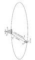
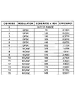
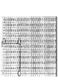
図1−図4を参照し、無線通信システムにおける適応変調符号化(AMC)について説明する。図1は、無線通信システムにおけるAMCの説明図である。図2は、AMCで用いられるCQIテーブルの一例を示す図である。図3は、AMCで用いられるMCSテーブルの一例を示す図である。図4は、AMCで用いられるTBSテーブルの一例を示す図である。 The adaptive modulation and coding (AMC) in the wireless communication system will be described with reference to FIGS. FIG. 1 is an explanatory diagram of AMC in a wireless communication system. FIG. 2 is a diagram illustrating an example of a CQI table used in AMC. FIG. 3 is a diagram illustrating an example of the MCS table used in AMC. FIG. 4 is a diagram illustrating an example of a TBS table used in AMC.
図1に示す無線通信システムにおいて、ユーザ端末UEは、無線基地局BSからの参照信号に基づいてチャネル品質を測定し、測定されたチャネル品質に基づいてチャネル品質識別子(CQI)を決定する(ステップS11)。具体的には、ユーザ端末UEは、図2に示すCQIテーブルを参照し、測定されたチャネル品質に適用可能な変調方式及び符号化率を示すCQIを決定する。なお、チャネル品質には、例えば、SINR(Signal to Interference Plus Noise Ratio)や、SNR(Signal to Noise Ratio)などが含まれる。 In the radio communication system shown in FIG. 1, the user terminal UE measures channel quality based on a reference signal from the radio base station BS, and determines a channel quality identifier (CQI) based on the measured channel quality (step). S11). Specifically, the user terminal UE refers to the CQI table shown in FIG. 2 and determines a CQI indicating a modulation scheme and a coding rate applicable to the measured channel quality. The channel quality includes, for example, SINR (Signal to Interference Plus Noise Ratio) and SNR (Signal to Noise Ratio).
図2に示すように、CQIテーブルでは、チャネル品質識別子(CQI)と変調方式と符号化率とが関連付けられる。例えば、図2では、ユーザ端末UEにおけるチャネル品質に応じて、変調方式及び符号化率の16種類の組み合わせが規定されている。このため、図2では、4ビットのCQIを設けることで、当該16種類の組み合わせを一意に識別できる。なお、CQIテーブルにおいて、CQIの値は、CQIインデックスと呼ばれてもよい。 As shown in FIG. 2, in the CQI table, a channel quality identifier (CQI), a modulation scheme, and a coding rate are associated. For example, in FIG. 2, 16 types of combinations of modulation schemes and coding rates are defined according to the channel quality in the user terminal UE. Therefore, in FIG. 2, the 16 types of combinations can be uniquely identified by providing a 4-bit CQI. In the CQI table, the CQI value may be referred to as a CQI index.
ユーザ端末UEは、図2に示すCQIテーブルを参照して決定されたCQIを無線基地局BSにフィードバックする(ステップS12)。例えば、図1では、CQIとして、4ビットのビット情報「0101(=5)」が、ユーザ端末UEから無線基地局BSにフィードバックされる。なお、CQIは、上り制御チャネル(PUCCH:Physical Uplink Control Channel)、上り共有チャネル(PUSCH:Physical Uplink Shared Channel)などを用いて、フィードバックされる。 The user terminal UE feeds back the CQI determined with reference to the CQI table shown in FIG. 2 to the radio base station BS (step S12). For example, in FIG. 1, 4-bit bit information “0101 (= 5)” is fed back from the user terminal UE to the radio base station BS as CQI. The CQI is fed back using an uplink control channel (PUCCH: Physical Uplink Control Channel), an uplink shared channel (PUSCH), or the like.
無線基地局BSは、ユーザ端末UEからフィードバックされたCQIに基づいて、下り共有チャネル(PDSCH)の変調符号化情報(MCS)を決定する(ステップS13)。具体的には、無線基地局BSは、図2に示すCQIテーブルを参照し、フィードバックされたCQIに対応する変調方式及び符号化率を取得する。また、無線基地局BSは、図3に示すMCSテーブルを参照し、取得された変調方式に対応する変調次数(Modulation Order)と、取得された符号化率に対応するトランスポートブロックサイズ(TBS)インデックスと、を示すMCSを取得する。 The radio base station BS determines modulation and coding information (MCS) of the downlink shared channel (PDSCH) based on the CQI fed back from the user terminal UE (step S13). Specifically, the radio base station BS refers to the CQI table shown in FIG. 2 and acquires the modulation scheme and coding rate corresponding to the fed back CQI. In addition, the radio base station BS refers to the MCS table shown in FIG. 3, and refers to the modulation order corresponding to the acquired modulation scheme and the transport block size (TBS) corresponding to the acquired coding rate. The MCS indicating the index is acquired.
図3に示すように、MCSテーブルでは、変調符号化情報(MCS)と変調次数とTBSインデックスとが関連付けられる。図3では、変調次数とTBSインデックスとの32種類の組み合わせが規定されている。このため、図3では、5ビットのMCSを設けることで、当該32種類の組み合わせを一意に識別できる。なお、MCSテーブルにおいて、MCSの値は、MCSインデックスと呼ばれてもよい。また、TBSインデックスとは、トランスポートブロックサイズ(TBS)を識別するトランスポートブロックサイズ(TBS)識別子である。 As shown in FIG. 3, in the MCS table, modulation and coding information (MCS), a modulation order, and a TBS index are associated. In FIG. 3, 32 types of combinations of modulation order and TBS index are defined. For this reason, in FIG. 3, by providing a 5-bit MCS, the 32 types of combinations can be uniquely identified. In the MCS table, the MCS value may be referred to as an MCS index. The TBS index is a transport block size (TBS) identifier that identifies a transport block size (TBS).
例えば、図1に示すように、CQIとして4ビットのビット情報「0101(=5)」がユーザ端末UEからフィードバックされる場合、無線基地局BSは、図2に示すCQIテーブルを参照して、変調方式として「QPSK」、符号化率として「449」を取得する。また、無線基地局BSは、図3に示すMCSテーブルを参照して、「QPSK」に対応する変調次数「2」と、符号化率「449」に対応するTBSインデックス「7」と、の組み合わせを示すMCS「7」を取得する。 For example, as shown in FIG. 1, when 4-bit bit information “0101 (= 5)” is fed back from the user terminal UE as CQI, the radio base station BS refers to the CQI table shown in FIG. “QPSK” is acquired as the modulation scheme, and “449” is acquired as the coding rate. Also, the radio base station BS refers to the MCS table shown in FIG. 3 and combines the modulation order “2” corresponding to “QPSK” and the TBS index “7” corresponding to the coding rate “449”. MCS “7” indicating “” is acquired.
無線基地局BSは、決定されたMCSをユーザ端末UEに通知する(ステップS14)。例えば、図1では、MCSとして、5ビットのビット情報「00111(=7)」が、無線基地局BSからユーザ端末UEに通知される。なお、MCSは、下り制御情報(DCI)に含まれ、下り制御チャネル(PDCCH:Physical Downlink Control Channel)、拡張下り制御チャネル(EPDCCH:Enhanced Physical Downlink Control Channel)などを用いて、通知される。 The radio base station BS notifies the user terminal UE of the determined MCS (step S14). For example, in FIG. 1, 5-bit bit information “00111 (= 7)” is notified from the radio base station BS to the user terminal UE as the MCS. The MCS is included in downlink control information (DCI), and is notified using a downlink control channel (PDCCH: Physical Downlink Control Channel), an enhanced downlink control channel (EPDCCH: Enhanced Physical Downlink Control Channel), and the like.
ユーザ端末UEは、無線基地局BSから通知されたMCSに基づいて、PDSCHの変調方式及び符号化率を取得する(ステップS15)。具体的には、ユーザ端末UEは、図3に示すMCSテーブルを参照し、フィードバックされたMCSに対応する変調次数及びTBSインデックスを取得する。ユーザ端末UEは、取得された変調次数に対応する変調方式を用いて、PDSCHを復調する。 The user terminal UE acquires the PDSCH modulation scheme and coding rate based on the MCS notified from the radio base station BS (step S15). Specifically, the user terminal UE refers to the MCS table shown in FIG. 3 and acquires the modulation order and TBS index corresponding to the fed back MCS. The user terminal UE demodulates the PDSCH using a modulation scheme corresponding to the acquired modulation order.
また、ユーザ端末UEは、図4に示すTBSテーブルを参照し、取得されたTBSインデックスと、DCIに含まれる1トランスポートブロックあたりの物理リソースブロック(PRB)数と、に対応するトランスポートブロックサイズ(TBS)を取得する。ユーザ端末UEは、取得されたTBSに基づいて、例えば、式(1)により、符号化率を算出する。ユーザ端末UEは、算出された符号化率を用いて、PDSCHを復号する。

例えば、図1に示すように、MCSとして5ビットのビット情報「00111(=7)」が無線基地局BSから通知される場合、ユーザ端末UEは、図3に示すMCSテーブルを参照して、MCS「7」に対応する変調次数「2」及びTBSインデックス「7」を取得する。ユーザ端末UEは、変調次数が「2」である変調方式「QPSK」を用いて、PDSCHを復調する。 For example, as shown in FIG. 1, when 5-bit bit information “00111 (= 7)” is notified from the radio base station BS as the MCS, the user terminal UE refers to the MCS table shown in FIG. A modulation order “2” and a TBS index “7” corresponding to MCS “7” are acquired. The user terminal UE demodulates the PDSCH using a modulation scheme “QPSK” having a modulation order of “2”.
また、ユーザ端末UEは、図4に示すMCSテーブルを参照して、TBSインデックス「7」と、DCIに含まれる1トランスポートブロックあたりのPRB数(ここでは、「6」とする)とに対応するTBS「712」を取得する。ユーザ端末UEは、取得されたTBSに基づいて、上述の式(1)により符号化率を算出し、算出された符号化率を用いて、PDSCHを復号する。 Further, the user terminal UE refers to the MCS table shown in FIG. 4 and corresponds to the TBS index “7” and the number of PRBs per transport block included in DCI (here, “6”). The TBS “712” to be acquired is acquired. Based on the acquired TBS, the user terminal UE calculates a coding rate according to the above equation (1), and decodes the PDSCH using the calculated coding rate.
以上のように、無線通信システムにおけるAMCでは、CQIとMCSとを用いて、PDSCHの変調方式及び符号化率が適応的に制御される。これにより、スペクトル効率が向上する。 As described above, in AMC in a wireless communication system, the PDSCH modulation scheme and coding rate are adaptively controlled using CQI and MCS. This improves the spectral efficiency.
ところで、マクロセル内にスモールセルが配置される無線通信システム(HetNet(Heterogeneous Network)ともいう)において、上述のAMCを適用することが検討されている。図5は、マクロセル内にスモールセルが配置される無線通信システムの構成例を示す図である。図5Aの構成では、マクロセルMとスモールセルS1及びS2との双方で同一の周波数F1が用いられる。一方、図5Bの構成では、マクロセルMで周波数F1が用いられ、スモールセルS1及びS2では周波数F2(例えば、F2>F1)が用いられる。 By the way, in the radio | wireless communications system (it is also called HetNet (Heterogeneous Network)) by which a small cell is arrange | positioned in a macrocell, applying the above-mentioned AMC is examined. FIG. 5 is a diagram illustrating a configuration example of a wireless communication system in which small cells are arranged in a macro cell. In the configuration of FIG. 5A, the same frequency F1 is used in both the macro cell M and the small cells S1 and S2. On the other hand, in the configuration of FIG. 5B, the frequency F1 is used in the macro cell M, and the frequency F2 (for example, F2> F1) is used in the small cells S1 and S2.
図5Aの構成では、スモールセルS1に接続するユーザ端末UEは、マクロセルM及びスモールセルS2の双方からの干渉を受ける。一方、図5Bの構成では、スモールセルS1に接続するユーザ端末UEは、スモールセルS2からの干渉を受けるが、マクロセルMからの干渉を受けない。このため、図5Bの構成では、ユーザ端末UEにおけるチャネル品質は、図5Aの構成に示す場合よりも、高くなることが想定される。 In the configuration of FIG. 5A, the user terminal UE connected to the small cell S1 receives interference from both the macro cell M and the small cell S2. On the other hand, in the configuration of FIG. 5B, the user terminal UE connected to the small cell S1 receives interference from the small cell S2, but does not receive interference from the macro cell M. For this reason, in the configuration of FIG. 5B, it is assumed that the channel quality in the user terminal UE is higher than in the case shown in the configuration of FIG. 5A.
ユーザ端末UEにおけるチャネル品質(例えば、SNR)が高くなると、図6Aに示すように、より高次の変調方式を適用可能となる。このため、ユーザ端末UEにおけるチャネル品質が高くなるにつれて、スペクトル効率が向上する。特に、256QAMをサポートする場合には、スペクトル効率の更なる向上が見込まれる。 When the channel quality (for example, SNR) in the user terminal UE increases, a higher-order modulation scheme can be applied as shown in FIG. 6A. For this reason, spectrum efficiency improves as channel quality in user terminal UE becomes high. In particular, when 256QAM is supported, further improvement in spectral efficiency is expected.
また、図6Bに示すように、マクロセルMと異なる周波数を用いるスモールセルS(図5B)では、マクロセルMや、マクロセルMと同じ周波数を用いるスモールセルS(図5A)と比較して、256QAMを適用可能なユーザ端末UE(すなわち、チャネル品質が20dBを超えるユーザ端末UE)が増加する。例えば、図6Bでは、マクロセルMと同じ周波数を用いるスモールセルSでは、約10%のユーザ端末UEにしか256QAMを適用できない。一方、マクロセルMと異なる周波数を用いるスモールセルSでは、約30%のユーザ端末UEに256QAMを適用可能となることが想定される。 In addition, as shown in FIG. 6B, in the small cell S (FIG. 5B) using a frequency different from that of the macro cell M, 256QAM is compared with the macro cell M or the small cell S (FIG. 5A) using the same frequency as the macro cell M. Applicable user terminals UE (that is, user terminals UE having a channel quality exceeding 20 dB) increase. For example, in FIG. 6B, in the small cell S using the same frequency as the macro cell M, 256QAM can be applied only to about 10% of the user terminals UE. On the other hand, in the small cell S using a frequency different from that of the macro cell M, it is assumed that 256QAM can be applied to about 30% of the user terminals UE.
したがって、マクロセルMとスモールセルSとで異なる周波数が用いられる無線通信システムでは、256QAMなどの高次変調方式をサポートすることが望まれる。しかしながら、図1−図4を参照して説明した適応変調符号化(AMC)では、QPSK、16QAM、64QAMがサポートされるにすぎない。 Therefore, in a wireless communication system in which different frequencies are used for the macro cell M and the small cell S, it is desired to support a higher-order modulation scheme such as 256QAM. However, the adaptive modulation and coding (AMC) described with reference to FIGS. 1 to 4 only supports QPSK, 16QAM, and 64QAM.
そこで、本発明者らは、64QAMよりも高次の変調方式をサポートする適応変調符号化(AMC)を可能とすることで、スペクトル効率を更に向上させるという着想を得て、本発明に至った。 Accordingly, the inventors have arrived at the present invention with the idea of further improving spectral efficiency by enabling adaptive modulation coding (AMC) that supports higher-order modulation schemes than 64QAM. .
以下、本発明に係る適応変調符号化方法を詳細に説明する。以下では、64QAMよりも高次の変調方式として256QAMをサポートする例を説明するが、これに限られない。64QAMよりも高次の変調方式として、128QAM、512QAM、1028QAM、…などがサポートされてもよい。また、以下の態様1−3に係る適応変調符号化方法は、適宜組み合わせ可能である。 Hereinafter, the adaptive modulation and coding method according to the present invention will be described in detail. In the following, an example of supporting 256QAM as a higher-order modulation scheme than 64QAM will be described, but the present invention is not limited to this. 128QAM, 512QAM, 1028QAM, etc. may be supported as a higher-order modulation scheme than 64QAM. Also, the adaptive modulation and coding methods according to aspects 1-3 below can be combined as appropriate.
(態様1)
態様1に係る適応変調符号化方法において、ユーザ端末UEは、無線基地局BSからの参照信号に基づいてチャネル品質を測定する。また、ユーザ端末UEは、チャネル品質識別子(CQI)と変調方式と符号化率とを関連付けるCQIテーブルから、測定されたチャネル品質において下り共有チャネル(PDSCH)に適用可能な変調方式及び符号化率を示すCQIを取得する。また、ユーザ端末UEは、取得されたCQIを無線基地局BSに送信する。ここで、CQIテーブルの変調方式は、64QAMよりも高次の変調方式を含む。
(Aspect 1)
In the adaptive modulation and coding method according to
具体的には、態様1に係る適応変調符号化方法では、図7に示すように、CQIと、変調方式と、符号化率とを関連付けるCQIテーブルが用いられる。図7に示すCQIテーブルでは、64QAMよりも高次の変調方式として、256QAMがサポートされる。なお、図7に示すCQIテーブルは、一例にすぎず、これに限られない。また、上述のように、CQIテーブルにおいて、CQIの値は、CQIインデックスと呼ばれもよい。
Specifically, in the adaptive modulation and coding method according to
図7に示すように、256QAMをサポートするCQIテーブルでは、256QAMをサポートしないCQIテーブル(図2)と比較して、変調方式及び符号化率の組み合わせが増加することが想定される。例えば、変調方式及び符号化率の組み合わせは、図2に示すCQIテーブルでは16種類であるのに対して、図7に示すCQIテーブルでは20種類に増加する。このため、4ビットのCQIを設けるだけでは、256QAMを含む変調方式及び符号化率の組み合わせを一意に識別できない。 As shown in FIG. 7, in the CQI table that supports 256QAM, it is assumed that the combination of modulation schemes and coding rates increases as compared to the CQI table that does not support 256QAM (FIG. 2). For example, the number of combinations of modulation schemes and coding rates is 16 in the CQI table shown in FIG. 2, but is increased in 20 in the CQI table shown in FIG. For this reason, a combination of a modulation scheme including 256QAM and a coding rate cannot be uniquely identified only by providing a 4-bit CQI.
このように、64QAMよりも高次の変調方式をCQIテーブルでサポートする場合、無線基地局BSにおいて、PDSCHに適用可能な変調方式及び符号化率を一意に識別できないことが想定される。そこで、態様1に係る適応変調符号化方法では、CQIテーブルにおけるCQIのビット数の増加に応じて、ユーザ端末UEから無線基地局BSへのフィードバックビット数を増加させる(態様1.1)。或いは、CQIテーブルにおけるCQIのビット数の増加に応じて、複数のサブテーブルを設ける(態様1.2)。或いは、CQIテーブルにおけるCQIのビット数を増加させずに、抽出テーブル(sampled table)を設ける(態様1.3)。
Thus, when a higher-order modulation scheme than 64QAM is supported by the CQI table, it is assumed that the radio base station BS cannot uniquely identify the modulation scheme and coding rate applicable to the PDSCH. Therefore, in the adaptive modulation and coding method according to
(態様1.1)
態様1.1に係る適応変調符号化方法では、CQIのビット数の増加に応じて、ユーザ端末UEから無線基地局BSへのフィードバックビット数を増加させる。これにより、256QAMを含む変調方式及び符号化率を一意に識別可能とする。
(Aspect 1.1)
In the adaptive modulation and coding method according to aspect 1.1, the number of feedback bits from the user terminal UE to the radio base station BS is increased in accordance with the increase in the number of CQI bits. This makes it possible to uniquely identify modulation schemes and coding rates including 256QAM.
具体的には、ユーザ端末UEは、上り制御チャネル(PUCCH)又は上り共有チャネル(PUSCH)におけるCQI用フィールドのサイズを拡張して、CQIを送信してもよい。例えば、図7に示す場合、PUCCH又はPUSCHにおけるCQI用フィールドのサイズは、4ビットから5ビットに拡張されてもよい。 Specifically, the user terminal UE may expand the size of the CQI field in the uplink control channel (PUCCH) or the uplink shared channel (PUSCH) and transmit the CQI. For example, in the case shown in FIG. 7, the size of the CQI field in PUCCH or PUSCH may be extended from 4 bits to 5 bits.
また、ユーザ端末UEは、CQIを構成する第1ビット部と第2ビット部とをジョイント符号化して、CQIを送信してもよい。例えば、図7に示す場合、図8に示すように、ユーザ端末UEは、第1ビット部(例えば、4ビットの既存ビット)と第2ビット部(例えば、1ビットの追加ビット)とをRMコード(Reed-Muller-based block code)を用いてジョイント符号化する。かかる場合、ユーザ端末UEは、PUCCH(例えば、PUCCHフォーマット2のExtended CP)を用いて、ジョイント符号化されたビットを無線基地局BSに送信してもよい。
Further, the user terminal UE may jointly encode the first bit part and the second bit part constituting the CQI and transmit the CQI. For example, in the case illustrated in FIG. 7, as illustrated in FIG. 8, the user terminal UE RMs a first bit part (for example, 4 existing bits) and a second bit part (for example, 1 additional bit). Joint encoding is performed using a code (Reed-Muller-based block code). In such a case, the user terminal UE may transmit the jointly encoded bits to the radio base station BS using PUCCH (for example,
また、ユーザ端末UEは、PUCCHにおけるCQI用フィールドと参照信号用フィールドとを用いて、CQIを送信してもよい。例えば、図7に示す場合、図9に示すように、ユーザ端末UEは、CQI用フィールド(ここでは、OFDMシンボル#0、#2−#4、#6)を用いて、第1ビット部(例えば、4ビットの既存ビット)を送信する。また、ユーザ端末UEは、参照信号用フィールド(ここでは、OFDMシンボル#5)を用いて、第2ビット部(例えば、追加の1ビット)を送信する。
Further, the user terminal UE may transmit CQI using the CQI field and the reference signal field in the PUCCH. For example, in the case illustrated in FIG. 7, as illustrated in FIG. 9, the user terminal UE uses the CQI field (here,
また、図9において、PUCCHフォーマット2aを用いる場合、参照信号用フィールド(ここでは、OFDMシンボル#5)において、HARQ用ビット(1ビット)に代えて、第2ビット部(例えば、追加の1ビット)がBPSKにより送信されてもよい。或いは、PUCCHフォーマット2bを用いる場合、参照信号用フィールド(ここでは、OFDMシンボル#5)において、HARQ用ビット(2ビット)に代えて、第2ビット部(例えば、追加の1ビット)とHARQ用ビット(1ビット)がQPSKにより送信されてもよい。かかる場合、PUCCHフォーマット2a/2bを再利用(reuse)できるので、CQIのビット数の増加に伴う実装負荷を軽減できる。 In FIG. 9, when the PUCCH format 2a is used, in the reference signal field (here, OFDM symbol # 5), instead of the HARQ bit (1 bit), the second bit part (for example, an additional 1 bit) ) May be transmitted by BPSK. Alternatively, when the PUCCH format 2b is used, in the reference signal field (here, OFDM symbol # 5), instead of the HARQ bit (2 bits), the second bit part (for example, an additional 1 bit) and the HARQ A bit (1 bit) may be transmitted by QPSK. In this case, since the PUCCH format 2a / 2b can be reused, the mounting load accompanying the increase in the number of CQI bits can be reduced.
なお、図9では、CQIの第2ビット部(例えば、追加の1ビット)は、1スロット内の2番目の参照信号用フィールド(OFDMシンボル#5)で送信されるものとするが、1スロット内の1番目の参照信号用フィールド(OFDMシンボル#1)で送信されてもよい。また、CQI用フィールド及び参照信号用フィールドの配置は、図9に示す例に限られない。 In FIG. 9, it is assumed that the second bit part (for example, one additional bit) of CQI is transmitted in the second reference signal field (OFDM symbol # 5) in one slot. The first reference signal field (OFDM symbol # 1) may be transmitted. Further, the arrangement of the CQI field and the reference signal field is not limited to the example shown in FIG.
(態様1.2)
態様1.2に係る適応変調符号化方法では、CQIテーブルにおけるCQIのビット数の増加に応じて、複数のサブテーブルを設ける。これにより、ユーザ端末UEから無線基地局BSへのフィードバックビット数を変更せずに、256QAMを含む変調方式及び符号化率を一意に識別可能とする。
(Aspect 1.2)
In the adaptive modulation and coding method according to aspect 1.2, a plurality of sub-tables are provided according to an increase in the number of CQI bits in the CQI table. This makes it possible to uniquely identify the modulation scheme and coding rate including 256QAM without changing the number of feedback bits from the user terminal UE to the radio base station BS.
態様1.2に係る適応変調符号化方法では、無線基地局BSとユーザ端末UEとの間で、CQIの開始値がシフトされたサブテーブルの使用が明示的に(explicitly)通知されてもよいし(図10)、明示的に通知されなくともよい(すなわち、暗示的に(implicitly)通知されてもよい)(図11)。 In the adaptive modulation and coding method according to aspect 1.2, use of the sub-table in which the start value of CQI is shifted may be explicitly notified between the radio base station BS and the user terminal UE. However, it may not be explicitly notified (that is, it may be notified implicitly) (FIG. 11).
図10を参照し、サブテーブルの使用が明示的に通知される場合を説明する。かかる場合、図10に示すように、CQIテーブルは、最小値(ここでは、「0」)から最大値よりも小さい終了値(ここでは、「15」)までのCQIを含む第1サブテーブル(SUB−TABLE1)と、最小値よりも大きい開始値(ここでは、「4」)から最大値(ここでは、「19」)までのCQIを含む第2サブテーブル(SUB−TABLE2)とを含んでもよい。なお、図10では、CQIのみが示されるが、図7に示すように、CQIと変調方式と符号化率とが関連付けられてもよい。また、第1及び第2サブテーブルの構成は、図10に示す構成に限られない。 With reference to FIG. 10, the case where the use of the sub-table is explicitly notified will be described. In this case, as shown in FIG. 10, the CQI table is a first sub-table including CQIs from a minimum value (here “0”) to an end value (here “15”) smaller than the maximum value. SUB-TABLE1) and a second sub-table (SUB-TABLE2) including CQI from a starting value (here, “4”) larger than the minimum value to a maximum value (here, “19”). Good. Although only CQI is shown in FIG. 10, CQI, modulation scheme, and coding rate may be associated with each other as shown in FIG. Further, the configuration of the first and second sub-tables is not limited to the configuration shown in FIG.
ここで、第2サブテーブルの開始値は、無線基地局BSからユーザ端末UEに対して通知されてもよいし、ユーザ端末UEから無線基地局BSに通知されてもよい。このように、無線基地局BSとユーザ端末UEとの間で第2サブテーブルの開始値を通知することで、第2サブテーブルの使用が明示的に通知される。 Here, the start value of the second sub-table may be notified from the radio base station BS to the user terminal UE, or may be notified from the user terminal UE to the radio base station BS. Thus, the use of the second subtable is explicitly notified by notifying the start value of the second subtable between the radio base station BS and the user terminal UE.
なお、第2サブテーブルの開始値は、無線基地局BSからユーザ端末UEに対して、RRCシグナリングなどの上位レイヤシグナリング、PDCCH、EPDCCH、報知チャネルなどを用いて、通知されてもよい。或いは、第2サブテーブルの開始値は、ユーザ端末UEから無線基地局BSに対して、RRCシグナリングなどの上位レイヤシグナリング、PUCCHなどを用いて、通知されてもよい。 Note that the start value of the second sub-table may be notified from the radio base station BS to the user terminal UE using higher layer signaling such as RRC signaling, PDCCH, EPDCCH, broadcast channel, or the like. Alternatively, the start value of the second subtable may be notified from the user terminal UE to the radio base station BS using higher layer signaling such as RRC signaling, PUCCH, or the like.
図10に示すように、第1サブテーブル及び第2サブテーブルが設けられる場合、ユーザ端末UEは、測定したチャネル品質においてPDSCHに適用可能な変調方式及び符号化率に対応するCQIと、第2サブテーブルの開始値と、に基づく演算結果を、無線基地局BSにフィードバックする。一方、無線基地局BSは、ユーザ端末UEからのフィードバック値と、第2サブテーブルの開始値と、に基づいて、PDSCHに適用可能な変調方式及び符号化率に対応するCQIを復元する。 As shown in FIG. 10, when the first sub-table and the second sub-table are provided, the user terminal UE uses the CQI corresponding to the modulation scheme and coding rate applicable to the PDSCH in the measured channel quality, and the second The calculation result based on the start value of the sub-table is fed back to the radio base station BS. On the other hand, the radio base station BS restores the CQI corresponding to the modulation scheme and coding rate applicable to the PDSCH based on the feedback value from the user terminal UE and the start value of the second subtable.
例えば、図10に示すように、CQIの最大値が「19」であり、第2サブテーブルの開始値が「4」である場合、測定したチャネル品質においてPDSCHに適用可能な変調方式及び符号化率に対応するCQIが「18」であるものとする。かかる場合、ユーザ端末UEは、以下の式(2)による演算結果「14」を、無線基地局BSに送信してもよい。
(CQIの最大値−第2サブテーブルの開始値+CQI)
mod CQIの最大値 …式(2)
=(19−4+18) mod 19=14
For example, as shown in FIG. 10, when the maximum value of CQI is “19” and the start value of the second sub-table is “4”, the modulation scheme and coding applicable to PDSCH in the measured channel quality It is assumed that the CQI corresponding to the rate is “18”. In such a case, the user terminal UE may transmit the calculation result “14” according to the following equation (2) to the radio base station BS.
(Maximum value of CQI−starting value of second sub-table + CQI)
mod CQI maximum value (2)
= (19-4 + 18)
一方、無線基地局BSは、ユーザ端末UEからのフィードバック値と第2サブテーブルの開始値とに基づいて、以下の式(3)により、PDSCHに適用すべき変調方式及び符号化率に対応するCQI「18」を復元してもよい。
(ユーザ端末UEからのフィードバック値+第2サブテーブルの開始値)
mod CQIの最大値 …式(3)
=(14+4) mod 19=18
On the other hand, based on the feedback value from the user terminal UE and the start value of the second sub table, the radio base station BS corresponds to the modulation scheme and coding rate to be applied to the PDSCH by the following equation (3). CQI “18” may be restored.
(Feedback value from user terminal UE + start value of second sub-table)
mod CQI maximum value Equation (3)
= (14 + 4)
なお、ユーザ端末UEにおける演算結果は、例えば、PUCCH又はPUSCHにおけるCQI用フィールドを用いて送信される。式(2)によると、図10に示す場合、第2サブテーブルに含まれるCQI「4」から「19」の演算結果は、「0」から「15」となる。また、無線基地局BSとユーザ端末UEとの間で第2サブテーブルの使用が明示的に通知されるので、PUCCH又はPUSCHにおける既存のCQI用フィールドを拡張せずとも、256QAMを含む変調方式及び符号化率を一意に識別できる。 In addition, the calculation result in the user terminal UE is transmitted using, for example, a CQI field in PUCCH or PUSCH. According to Expression (2), in the case shown in FIG. 10, the calculation results from CQI “4” to “19” included in the second sub-table are “0” to “15”. In addition, since the use of the second sub-table is explicitly notified between the radio base station BS and the user terminal UE, a modulation scheme including 256QAM without extending the existing CQI field in the PUCCH or PUSCH, and The coding rate can be uniquely identified.
次に、図11を参照し、サブテーブルの使用を明示的に通知しない場合を説明する。かかる場合、図11に示すように、CQIテーブルは、最小値(ここでは、「0」)から最大値よりも小さい終了値(ここでは、「15」)までのCQIを含む第1サブテーブル(SUB−TABLE1)と、最小値よりも大きい開始値(ここでは、「4」)から最大値(ここでは、「19」)までのチャネル品質識別子を含む第2サブテーブル(SUB−TABLE2)とを含んでもよい。なお、図11では、CQIとフィードバック値とが関連付けられるが、図7に示すように、CQIと変調方式と符号化率とが更に関連付けられてもよい。なお、フィードバック値は、CQIに基づいて演算されれば、明示的に関連付けられていなくともよい。また、第1及び第2サブテーブルの構成は、図11に示す構成に限られない。 Next, with reference to FIG. 11, a case where the use of the subtable is not explicitly notified will be described. In this case, as shown in FIG. 11, the CQI table is a first sub-table including CQIs from a minimum value (here “0”) to an end value (here “15”) smaller than the maximum value. SUB-TABLE1) and a second sub-table (SUB-TABLE2) including channel quality identifiers from a start value (here, “4”) greater than the minimum value to a maximum value (here, “19”). May be included. In FIG. 11, the CQI and the feedback value are associated with each other. However, as shown in FIG. 7, the CQI, the modulation scheme, and the coding rate may be further associated with each other. Note that the feedback value may not be explicitly associated as long as it is calculated based on the CQI. Further, the configuration of the first and second sub-tables is not limited to the configuration shown in FIG.
第2サブテーブルの使用を明示的に通知しない場合、無線基地局BSは、CQIの履歴(history)に基づいて、第2サブテーブルが使用されるか否かを判断し、判断結果に基づいて、PDSCHに適用される変調方式及び符号化率に対応するCQIを復元する。 If the use of the second sub-table is not explicitly notified, the radio base station BS determines whether or not the second sub-table is used based on the CQI history, and based on the determination result The CQI corresponding to the modulation scheme and coding rate applied to the PDSCH is restored.
具体的には、ユーザ端末UEは、測定したチャネル品質においてPDSCHに適用可能な変調方式及び符号化率に対応するCQIに基づく演算結果を、無線基地局BSにフィードバックする。一方、無線基地局BSは、CQIの履歴に基づいて第2サブテーブルが使用されるか否かを判断し、判断結果とユーザ端末UEからのフィードバック値に基づいて、PDSCHに適用される変調方式及び符号化率に対応するCQIを復元する。 Specifically, the user terminal UE feeds back a calculation result based on the CQI corresponding to the modulation scheme and coding rate applicable to the PDSCH in the measured channel quality to the radio base station BS. On the other hand, the radio base station BS determines whether or not the second sub-table is used based on the CQI history, and based on the determination result and the feedback value from the user terminal UE, the modulation scheme applied to the PDSCH And CQI corresponding to the coding rate is restored.
例えば、図11に示すように、第1サブテーブルに含まれるCQIの数が「16」である場合、ユーザ端末UEは、以下の式(4)による演算結果を、無線基地局BSに送信してもよい。
(CQI) mod 16 …式(4)
For example, as illustrated in FIG. 11, when the number of CQIs included in the first sub-table is “16”, the user terminal UE transmits a calculation result according to the following equation (4) to the radio base station BS. May be.
(CQI)
ここで、ユーザ端末UEからのフィードバック値が「1」である場合、第1サブテーブルが使用されていれば、CQIは「1」である。一方、第2サブテーブルが使用されていれば、CQIは「17」である。そこで、無線基地局BSは、CQIの履歴に基づいて、第2サブテーブルが使用されているかを判断する。 Here, when the feedback value from the user terminal UE is “1”, the CQI is “1” if the first sub-table is used. On the other hand, if the second sub-table is used, the CQI is “17”. Therefore, the radio base station BS determines whether the second sub-table is used based on the CQI history.
例えば、前回のCQIが所定値(例えば、「15」)以上である場合、無線基地局BSは、第2サブテーブルが使用されると判断し、今回のCQIを「17」とする。一方、前回のCQIが所定値(例えば、「15」)未満である場合、無線基地局BSは、第2サブテーブルが使用されない(第1サブテーブルが使用される)と判断し、今回のCQIを「1」とする。 For example, when the previous CQI is a predetermined value (for example, “15”) or more, the radio base station BS determines that the second sub-table is used, and sets the current CQI to “17”. On the other hand, when the previous CQI is less than a predetermined value (for example, “15”), the radio base station BS determines that the second subtable is not used (the first subtable is used), and the current CQI Is “1”.
或いは、無線基地局BSは、復元されたCQIが第1サブテーブルのCQIの最大値(例えば、「15」)である場合、以降のフィードバック値に第2サブテーブルが使用されると判断してもよい。一方、無線基地局BSは、復元されたCQIが第2サブテーブルのCQIの最小値(例えば、「4」)である場合、以降のフィードバック値に第2サブテーブルが使用されない(第1サブテーブルが使用される)と判断してもよい。 Alternatively, the radio base station BS determines that the second sub-table is used for the subsequent feedback value when the restored CQI is the maximum value (for example, “15”) of the CQI in the first sub-table. Also good. On the other hand, when the restored CQI is the minimum value (for example, “4”) of the second subtable, the radio base station BS does not use the second subtable for the subsequent feedback values (first subtable). May be used).
なお、ユーザ端末UEにおけるフィードバック値は、例えば、PUCCH又はPUSCHにおけるCQI用フィールドを用いて送信される。式(4)によると、図11に示す場合、第1サブテーブル及び第2サブテーブルに含まれるCQI「1」から「19」の演算結果は、「0」から「15」となる。また、無線基地局BSは、CQIの履歴に基づいて第2サブテーブルが使用されるか否かを判断できる。このため、PUCCH又はPUSCHにおける既存のCQI用フィールドを拡張せずとも、256QAMを含む変調方式及び符号化率を一意に識別できる。また、複数のサブテーブルの応用例として、接続する無線基地局BSの種類に応じてテーブルを切り替える方法、ユーザ端末UEの能力に応じて切り替える方法も含まれる。 Note that the feedback value in the user terminal UE is transmitted using a CQI field in the PUCCH or PUSCH, for example. According to Expression (4), in the case shown in FIG. 11, the calculation results of CQI “1” to “19” included in the first sub-table and the second sub-table are “0” to “15”. Also, the radio base station BS can determine whether or not the second sub-table is used based on the CQI history. Therefore, it is possible to uniquely identify the modulation scheme and coding rate including 256QAM without extending the existing CQI field in PUCCH or PUSCH. In addition, as an application example of the plurality of sub-tables, a method of switching the table according to the type of the radio base station BS to be connected and a method of switching according to the capability of the user terminal UE are included.
(態様1.3)
態様1.3に係る適応変調符号化方法では、CQIテーブルにおけるCQIのビット数を増加させずに、抽出テーブル(sampled table)を設ける。これにより、ユーザ端末UEから無線基地局BSへのフィードバックビット数を変更せずに、256QAMを含む変調方式及び符号化率を一意に識別可能とする。
(Aspect 1.3)
In the adaptive modulation and coding method according to aspect 1.3, a sampled table is provided without increasing the number of CQI bits in the CQI table. This makes it possible to uniquely identify the modulation scheme and coding rate including 256QAM without changing the number of feedback bits from the user terminal UE to the radio base station BS.
具体的には、CQIテーブルは、図12に示すように、図7に示すCQIテーブルから、変調方式と符号化率との組み合わせが、線形的に(linearly)パンクチャされ、所定数(ここでは、16種類)の組み合わせが抽出されたものであってもよい。例えば、図12では、QPSK、16QAM、64QAM、256QAMの各変調方式において、一つの符号化率がパンクチャされる。 Specifically, as shown in FIG. 12, the CQI table is obtained by linearly puncturing combinations of modulation schemes and coding rates from the CQI table shown in FIG. 16 types) of combinations may be extracted. For example, in FIG. 12, one coding rate is punctured in each of the modulation schemes QPSK, 16QAM, 64QAM, and 256QAM.
また、CQIテーブルは、図13に示すように、図7に示すCQIテーブルから、変調方式と符号化率との組み合わせが、非線形的に(Non-linearly)パンクチャされ、所定数(ここでは、16種類)の組み合わせが抽出されたものであってもよい。例えば、図13では、QPSKや16QAMなどの、より低次の変調方式において、多くの符号化率がパンクチャされている。256QAMなどの高次の変調方式が適用される環境においては、QPSK、16QAMなどの低次の変調方式が適用される確率は低くなることが想定される。このため、低次の変調方式をより多くパンクチャすることで、高次の変調方式の適用によるスペクトル効率を一層向上させることができる。 Further, as shown in FIG. 13, the CQI table is non-linearly punctured with combinations of modulation schemes and coding rates from the CQI table shown in FIG. A combination of types) may be extracted. For example, in FIG. 13, many coding rates are punctured in lower-order modulation schemes such as QPSK and 16QAM. In an environment where a high-order modulation scheme such as 256QAM is applied, it is assumed that the probability that a low-order modulation scheme such as QPSK or 16QAM will be applied is low. For this reason, the spectrum efficiency by application of a high-order modulation system can be further improved by puncturing more low-order modulation systems.
以上の態様1.3に係る適応変調符号化方法によれば、既存のCQIのビット数(例えば、4ビット)に対応した抽出テーブルが設けられる。このため、PUCCH又はPUSCHにおける既存のCQI用フィールドを拡張せずとも、256QAMを含む変調方式及び符号化率を一意に識別できる。 According to the adaptive modulation and coding method according to aspect 1.3 above, an extraction table corresponding to the number of existing CQI bits (for example, 4 bits) is provided. Therefore, it is possible to uniquely identify the modulation scheme and coding rate including 256QAM without extending the existing CQI field in PUCCH or PUSCH.
(態様1.4)
態様1.4に係る適応変調符号化方法では、態様1.3と同様に、CQIテーブルにおけるCQIのビット数を増加させずに、所定の変調方式と符号化率との組み合わせが抽出される抽出テーブル(sampled table)が設けられる。
(Aspect 1.4)
In the adaptive modulation and coding method according to aspect 1.4, extraction in which a combination of a predetermined modulation scheme and coding rate is extracted without increasing the number of CQI bits in the CQI table, as in aspect 1.3 A table (sampled table) is provided.
具体的には、態様1.4に係る適応変調符号化方法では、低次の変調方式(例えば、QPSK)と符号化率との組み合わせは維持される。一方、高次の変調方式(例えば、16QAM、64QAM、256QAMなど)と符号化率との組み合わせが、スループットへの貢献度に基づいてパンクチャされる。ここで、スループットへの貢献度は、周波数利用効率の増加分や、CQIの使用確率などで示されてもよい。 Specifically, in the adaptive modulation and coding method according to aspect 1.4, a combination of a low-order modulation scheme (for example, QPSK) and a coding rate is maintained. On the other hand, combinations of higher-order modulation schemes (for example, 16QAM, 64QAM, 256QAM, etc.) and coding rates are punctured based on the contribution to throughput. Here, the degree of contribution to the throughput may be indicated by an increase in frequency utilization efficiency, a CQI use probability, or the like.
例えば、図37Bに示すCQIテーブルでは、QPSKと符号化率との組み合わせは、パンクチャされずに、維持される。セル端のユーザ端末UEは、低次のQPSKと符号化率との組み合わせを用いることが想定される。このため、QPSKと符号化率との組み合わせを維持することで、セル端のユーザ端末UEが所望の受信品質で受信できなくなるのを防止できる。 For example, in the CQI table shown in FIG. 37B, the combination of QPSK and coding rate is maintained without being punctured. It is assumed that the user terminal UE at the cell edge uses a combination of low-order QPSK and a coding rate. For this reason, it can prevent that the user terminal UE of a cell edge becomes unable to receive with desired reception quality by maintaining the combination of QPSK and a code rate.
一方、図37Bに示すCQIテーブルでは、16QAMよりも高次の変調方式と符号化率との組み合わせの中から、スループットへの貢献度が低い組み合わせが選択され、パンクチャされる。図37Aでは、16QAMよりも高次の変調方式において、CQI=7、10、16、18におけるゲイン(スループットへの貢献度)が相対的に低い。このため、図37Bに示すCQIテーブルでは、CQI=7、10、16、18に対応する変調方式と符号化率との組み合わせがパンクチャされる。なお、図37Bは、例示にすぎず、図37Bとは異なるパンクチャが行われてもよい。 On the other hand, in the CQI table shown in FIG. 37B, a combination having a lower contribution to the throughput is selected and punctured from combinations of higher-order modulation schemes and coding rates than 16QAM. In FIG. 37A, gain (contribution to throughput) at CQI = 7, 10, 16, 18 is relatively low in a higher-order modulation scheme than 16QAM. Therefore, in the CQI table shown in FIG. 37B, combinations of modulation schemes and coding rates corresponding to CQI = 7, 10, 16, 18 are punctured. Note that FIG. 37B is merely an example, and puncturing different from that in FIG. 37B may be performed.
以上の態様1.4に係る適法変調符号化方法によれば、低次の変調方式と符号化率との組み合わせを維持しながら、高次の変調方式と符号化率との組み合わせの中からスループットへの貢献度が低い組み合わせがパンクチャされる。このため、CQIテーブルのCQIのビット数の増加を防ぎながら、セル端のユーザ端末UEにおいて所望の受信品質を確保できる。 According to the lawful modulation coding method according to aspect 1.4 above, while maintaining the combination of the low-order modulation scheme and the coding rate, the throughput can be selected from the combinations of the high-order modulation scheme and the coding rate. A combination with a low contribution to is punctured. Therefore, desired reception quality can be ensured in the user terminal UE at the cell edge while preventing an increase in the number of CQI bits in the CQI table.
(態様1.5)
態様1.5に係る適応変調符号化方法では、所定の変調方式と符号化率の組み合わせをパンクチャする(態様1.3及び1.4参照)代わりに、所定の変調方式と符号化率の組み合わせが、64QAMよりも高次の変調方式(例えば、256QAM)と符号化率との組み合わせに置換(replace)される。このように、既存の変調方式と符号化率との組み合わせを置換することで、CQIテーブルのCQIのビット数を増加させずとも、256QAMと符号化率との組み合わせをサポートできる。
(Aspect 1.5)
In the adaptive modulation and coding method according to aspect 1.5, instead of puncturing a combination of a predetermined modulation scheme and coding rate (see aspects 1.3 and 1.4), a combination of the predetermined modulation scheme and coding rate Is replaced with a combination of a higher-order modulation scheme (for example, 256QAM) than 64QAM and a coding rate. Thus, by replacing the combination of the existing modulation scheme and coding rate, the combination of 256QAM and coding rate can be supported without increasing the number of CQI bits in the CQI table.
具体的には、CQIテーブルは、図38に示すように、図2に示すCQIテーブルから、所定の変調方式と符号化率との組み合わせが、線形的に(linearly)、256QAMと符号化率との組み合わせに置換されたものであってもよい。なお、図38は、例示にすぎず、図38とは異なる置換が行われてもよい。 Specifically, as shown in FIG. 38, the CQI table has a combination of a predetermined modulation scheme and coding rate linearly, 256QAM, coding rate, and the like from the CQI table shown in FIG. It may be replaced by a combination of Note that FIG. 38 is merely an example, and substitution different from that in FIG. 38 may be performed.
また、CQIテーブルは、図39に示すように、図2に示すCQIテーブルから、所定の変調方式と符号化率との組み合わせが、非線形的に(Non-linearly)、256QAMと符号化率との組み合わせに置換されたものであってもよい。例えば、図39では、QPSK、16QAMなどの低次の変調方式と符号化率の組み合わせが、256QAMと符号化率との組み合わせに置換される。なお、置換される変調方式と符号化率との組み合わせは、受信品質(例えば、SINRなど)に基づいて選択されてもよい。また、図39は、例示にすぎず、図39とは異なる置換が行われてもよい。 Further, as shown in FIG. 39, the CQI table is a non-linear combination of a predetermined modulation scheme and coding rate based on the CQI table shown in FIG. A combination may be substituted. For example, in FIG. 39, a combination of a low-order modulation scheme such as QPSK or 16QAM and a coding rate is replaced with a combination of 256QAM and a coding rate. Note that the combination of the modulation scheme to be replaced and the coding rate may be selected based on reception quality (for example, SINR). Also, FIG. 39 is merely an example, and a different substitution from that in FIG. 39 may be performed.
256QAMなどの高次の変調方式が適用される環境(例えば、スモールセル)においては、QPSKなどの低次の変調方式が適用される確率は低くなることが想定される。このため、低次の変調方式をより多く置換することで、高次の変調方式の適用によるスペクトル効率を一層向上させることができる。 In an environment where a high-order modulation scheme such as 256QAM is applied (for example, a small cell), it is assumed that the probability that a low-order modulation scheme such as QPSK is applied is low. For this reason, by replacing more low-order modulation schemes, it is possible to further improve the spectral efficiency due to the application of higher-order modulation schemes.
以上の態様1.5に係る適応変調符号化方法によれば、既存のCQIのビット数(例えば、4ビット)を維持できる。このため、PUCCH又はPUSCHにおける既存のCQI用フィールドを拡張せずとも、256QAMを含む変調方式及び符号化率を一意に識別できる。 According to the adaptive modulation and coding method according to aspect 1.5 described above, the number of existing CQI bits (for example, 4 bits) can be maintained. Therefore, it is possible to uniquely identify the modulation scheme and coding rate including 256QAM without extending the existing CQI field in PUCCH or PUSCH.
(態様2)
態様2に係る適応変調符号化方法において、無線基地局BSは、ユーザ端末UEから、下り共有チャネル(PDSCH)に適用可能な変調方式及び符号化率を示すチャネル品質識別子(CQI)を受信する。また、無線基地局BSは、変調符号化情報(MCS)と変調次数とTBSインデックス(トランスポートブロックサイズ識別子)とを関連付けるMCSテーブルから、前記変調方式及び符号化率に対応する変調次数及びTBSインデックスを示すMCSを取得する。また、無線基地局BSは、取得されたMCSをユーザ端末UEに送信する。ここで、MCSテーブルの変調次数は、64QAMよりも高次の変調方式の変調次数を含む。
(Aspect 2)
In the adaptive modulation and coding method according to
具体的には、態様2に係る適応変調符号化方法では、図14に示すように、変調符号化情報(MCS)と変調次数とTBSインデックスとを関連付けるMCSテーブルが用いられる。図14に示すMCSテーブルでは、64QAMよりも高次の変調方式として、256QAMの変調次数「8」がサポートされる。
Specifically, in the adaptive modulation and coding method according to
なお、図14に示すMCSテーブルは、一例にすぎず、これに限られない。例えば、図14に示すMCSテーブルにおける、スペクトル効率とコメントと符号化率とは、省略されてもよい。また、MCSテーブルにおいて、MCSの値は、MCSインデックスと呼ばれてもよい。 Note that the MCS table shown in FIG. 14 is merely an example, and the present invention is not limited to this. For example, the spectral efficiency, comments, and coding rate in the MCS table shown in FIG. 14 may be omitted. In the MCS table, the MCS value may be referred to as an MCS index.
図14に示すように、256QAMをサポートするMCSテーブルでは、256QAMをサポートしないMCSテーブル(図3)と比較して、変調次数及びTBSインデックスの組み合わせが増加することが想定される。例えば、変調次数及びTBSインデックスの組み合わせは、図3に示すMCSテーブルでは32種類であるのに対して、図14に示すMCSテーブルでは40種類に増加する。このため、5ビットのMCSを設けるだけでは、256QAMを含む変調方式の変調次数及びTBSインデックスの組み合わせを一意に識別できない。 As shown in FIG. 14, in the MCS table that supports 256QAM, it is assumed that the combination of the modulation order and the TBS index increases as compared with the MCS table that does not support 256QAM (FIG. 3). For example, the number of combinations of the modulation order and the TBS index is increased to 32 types in the MCS table shown in FIG. 14 while it is 32 types in the MCS table shown in FIG. For this reason, the combination of the modulation order and the TBS index of the modulation scheme including 256QAM cannot be uniquely identified only by providing a 5-bit MCS.
このように、64QAMよりも高次の変調方式の変調次数をMCSテーブルでサポートする場合、ユーザ端末UEにおいて、PDSCHに適用される変調方式及び符号化率を一意に識別できないことが想定される。そこで、態様2に係る適応変調符号化方法では、MCSテーブルにおけるMCSのビット数の増加に応じて、無線基地局BSからユーザ端末UEへの通知ビット数を増加させる(態様2.1)。或いは、MCSテーブルにおけるMCSのビット数の増加に応じて、複数のサブテーブルを設ける(態様2.2)。或いは、MCSテーブルにおけるMCSのビット数を増加させずに、抽出テーブル(sampled table)を設ける(態様2.3)。
Thus, when the MCS table supports a modulation order of a higher-order modulation scheme than 64QAM, it is assumed that the modulation scheme and coding rate applied to the PDSCH cannot be uniquely identified in the user terminal UE. Therefore, in the adaptive modulation and coding method according to
(態様2.1)
態様2.1に係る適応変調符号化方法では、MCSのビット数の増加に応じて、無線基地局BSからユーザ端末UEへの通知ビット数を増加させる。これにより、ユーザ端末UEが、256QAMを含む変調方式及び符号化率を一意に識別可能とする。
(Aspect 2.1)
In the adaptive modulation and coding method according to aspect 2.1, the number of notification bits from the radio base station BS to the user terminal UE is increased in accordance with the increase in the number of MCS bits. Accordingly, the user terminal UE can uniquely identify the modulation scheme and coding rate including 256QAM.
具体的には、無線基地局BSは、下り制御情報(DCI)におけるMCS用フィールドのサイズを拡張して、MCSを送信してもよい。例えば、図14に示す場合、DCIにおけるMCS用フィールドのサイズは、5ビットから6ビットに拡張されてもよい。なお、MCS用フィールドを含むDCIは、下り制御チャネル(PDCCH)で送信される。 Specifically, the radio base station BS may transmit the MCS by expanding the size of the MCS field in the downlink control information (DCI). For example, in the case shown in FIG. 14, the size of the MCS field in DCI may be expanded from 5 bits to 6 bits. The DCI including the MCS field is transmitted on the downlink control channel (PDCCH).
また、無線基地局BSは、DCIにおけるMCS用フィールドと、DCIに付加されるCRC(Cyclic Redundancy Check)のマスク(masking)とを用いて、MCSを送信してもよい。例えば、図14に示す場合、図15に示すように、無線基地局BSは、DCIにおけるMCSフィールドを用いて、MCSを構成する第1ビット部(例えば、5ビットの既存ビット)を送信する。また、無線基地局BSは、DCIに付加されるCRCを、MCSを構成する第2ビット部(例えば、1ビットの追加ビット)を示す系列によりマスクして、送信する。 Also, the radio base station BS may transmit the MCS using the MCS field in DCI and a CRC (Cyclic Redundancy Check) masking added to the DCI. For example, in the case illustrated in FIG. 14, as illustrated in FIG. 15, the radio base station BS transmits a first bit portion (for example, 5 existing bits) configuring the MCS using the MCS field in DCI. Also, the radio base station BS transmits the CRC added to the DCI by masking it with a sequence indicating the second bit part (for example, one additional bit) constituting the MCS.
例えば、図15では、DCIに付加されるCRC系列Ckは、初期系列Cinitial_kと、ユーザ端末UEに付与されるRNTI(Radio Network Temporary Identifier)系列Rkと、MCSの第2ビット部(例えば、1ビットの追加ビット)を示す系列Hkに基づいて、例えば、式(5)により生成される。
Ck=(Cinitial_k+Rk+Hk) mod 2(k=0,…,15)
… 式(5)
For example, in FIG. 15, a CRC sequence C k added to DCI includes an initial sequence C initial_k , an RNTI (Radio Network Temporary Identifier) sequence R k assigned to the user terminal UE, and a second bit part (for example, MCS) Based on the sequence H k indicating 1 additional bit), for example, it is generated by Expression (5).
C k = (C initial — k + R k + H k ) mod 2 (k = 0,..., 15)
... Formula (5)
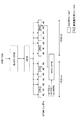
一方、ユーザ端末UEは、例えば、図16に示すフローに従って、MCSを復元する。図15に示すように、ユーザ端末UEは、DCIに付加されたCRC系列をチェック(抽出)する(ステップS101)。ユーザ端末UEは、CRC系列と自端末に付与されたRNTI系列との排他的論理和(XOR)を演算し(ステップS102)、ステップS102の演算結果と‘0’との排他的論理和(XOR)を演算する(ステップS103)。ユーザ端末UEは、ステップS103の演算結果によりCRCが通るか否かを判定する(ステップS104)。 On the other hand, the user terminal UE restores the MCS, for example, according to the flow shown in FIG. As illustrated in FIG. 15, the user terminal UE checks (extracts) the CRC sequence added to the DCI (step S101). The user terminal UE calculates the exclusive OR (XOR) of the CRC sequence and the RNTI sequence assigned to the terminal (step S102), and the exclusive OR (XOR) of the calculation result of step S102 and “0”. ) Is calculated (step S103). The user terminal UE determines whether CRC passes through the calculation result of step S103 (step S104).
ステップS103の演算結果によりCRCが通る場合(ステップS104;Yes)、ユーザ端末UEは、MCSの第2ビット部(例えば、1ビットの追加ビット)の値が「0」であると判断する(ステップS105)。一方、CRCが通らない場合(ステップS104;No)、ユーザ端末UEは、ステップS103の演算結果と‘1’との排他的論理和(XOR)を演算し(ステップS106)、演算結果によりCRCが通るか否かを判定する(ステップS107)。 When the CRC passes through the calculation result of step S103 (step S104; Yes), the user terminal UE determines that the value of the second bit part (for example, one additional bit) of the MCS is “0” (step S104). S105). On the other hand, when the CRC does not pass (step S104; No), the user terminal UE calculates an exclusive OR (XOR) of the calculation result of step S103 and “1” (step S106). It is determined whether or not it passes (step S107).
ステップS106の演算結果によりCRCが通る場合(ステップS107;Yes)、ユーザ端末UEは、MCSの第2ビット部(例えば、1ビットの追加ビット)の値が「1」であると判断する(ステップS108)。一方、CRCが通らない場合(ステップS107;No)、ユーザ端末UEは、MCSの第2ビット部によるマスクが行なわれていないと判断する(ステップS109)。本動作は、ステップS101に戻り、次のPDCCH候補位置のCRC系列のチェックに移行する。 When the CRC passes through the calculation result of Step S106 (Step S107; Yes), the user terminal UE determines that the value of the second bit part (for example, 1 additional bit) of the MCS is “1” (Step S107). S108). On the other hand, when the CRC does not pass (step S107; No), the user terminal UE determines that masking by the second bit part of the MCS is not performed (step S109). This operation returns to step S101 and shifts to a check of the CRC sequence at the next PDCCH candidate position.
ユーザ端末UEは、DCIをブラインド復号する(ステップS110)。ユーザ端末UEは、DCIのMCSフィールドに含まれる第1ビット部(例えば、4ビットの既存ビット)の値と、ステップS105又はステップS108で判断された第2ビット部(例えば、1ビットの既存ビット)の値とを結合して、MCSを取得する(ステップS111)。 The user terminal UE performs blind decoding on DCI (step S110). The user terminal UE determines the value of the first bit part (for example, 4 existing bits) included in the MCS field of DCI and the second bit part (for example, 1 existing bit) determined in step S105 or step S108. ) And the MCS is acquired (step S111).
(態様2.2)
態様2.2に係る適応変調符号化方法では、MCSテーブルにおけるMCSのビット数の増加に応じて、複数のサブテーブルを設ける。これにより、無線基地局BSからユーザ端末UEへの通知ビット数を変更せずに、256QAMを含む変調方式及び符号化率を一意に識別可能とする。
(Aspect 2.2)
In the adaptive modulation and coding method according to aspect 2.2, a plurality of sub-tables are provided according to an increase in the number of MCS bits in the MCS table. This makes it possible to uniquely identify the modulation scheme and coding rate including 256 QAM without changing the number of bits reported from the radio base station BS to the user terminal UE.
態様2.2に係る適応変調符号化方法では、無線基地局BSとユーザ端末UEとの間で、MCSの開始値がシフトされたサブテーブルの使用が明示的に(explicitly)通知されてもよいし(図17)、明示的に通知されなくともよい(すなわち、暗示的に(implicitly)通知されてもよい)(図18)。 In the adaptive modulation and coding method according to aspect 2.2, the use of the sub-table in which the start value of MCS is shifted may be explicitly notified between the radio base station BS and the user terminal UE. However, it may not be explicitly notified (that is, it may be notified implicitly) (FIG. 18).
図17を参照し、サブテーブルの使用が明示的に通知される場合を説明する。かかる場合、図17に示すように、MCSテーブルは、最小値(ここでは、「0」)から最大値よりも小さい終了値(ここでは、「31」)までのMCSを含む第1サブテーブル(SUB−TABLE1)と、最小値よりも大きい開始値(ここでは、「8」)から最大値(ここでは、「39」)までのMCSを含む第2サブテーブル(SUB−TABLE2)とを含んでもよい。なお、図17では、MCSのみが示されるが、図14に示すように、MCSと変調次数とTBSインデックスなどが関連付けられてもよい。 With reference to FIG. 17, a case where the use of the sub-table is explicitly notified will be described. In this case, as shown in FIG. 17, the MCS table is a first sub-table including MCS from a minimum value (here “0”) to an end value (here “31”) smaller than the maximum value. SUB-TABLE1) and a second sub-table (SUB-TABLE2) including MCS from a start value (here “8”) larger than the minimum value to a maximum value (here “39”). Good. In FIG. 17, only MCS is shown, but as shown in FIG. 14, MCS, modulation order, TBS index, and the like may be associated with each other.
ここで、第2サブテーブルの開始値は、無線基地局BSからユーザ端末UEに対して通知される。例えば、無線基地局BSは、RRCシグナリングなどの上位レイヤシグナリング、PDCCH、EPDCCH、報知チャネルなどを用いて、第2サブテーブルの開始値を通知してもよい。このように、無線基地局BSがユーザ端末UEに対して第2サブテーブルの開始値を通知することで、第2サブテーブルの使用が明示的に通知される。 Here, the start value of the second sub-table is notified from the radio base station BS to the user terminal UE. For example, the radio base station BS may notify the start value of the second sub-table using higher layer signaling such as RRC signaling, PDCCH, EPDCCH, broadcast channel, and the like. In this way, the radio base station BS notifies the user terminal UE of the start value of the second sub table, so that the use of the second sub table is explicitly notified.
図17に示すように、第1サブテーブル及び第2サブテーブルが設けられる場合、無線基地局BSは、PDSCHに適用される変調方式及び符号化率に対応する変調次数及びTBSインデックスを示すMCSと、第2サブテーブルの開始値と、に基づく演算結果を、ユーザ端末UEに通知する。一方、ユーザ端末UEは、無線基地局BSからの通知値と、第2サブテーブルの開始値と、に基づいて、PDSCHに適用される変調方式及び符号化率に対応するMCSを復元する。 As shown in FIG. 17, when the first sub-table and the second sub-table are provided, the radio base station BS uses the MCS indicating the modulation order and the TBS index corresponding to the modulation scheme and coding rate applied to the PDSCH. The user terminal UE is notified of the calculation result based on the start value of the second sub-table. On the other hand, the user terminal UE restores the MCS corresponding to the modulation scheme and coding rate applied to the PDSCH based on the notification value from the radio base station BS and the start value of the second subtable.
例えば、図17に示すように、MCSの最大値が「39」であり、第2サブテーブルの開始値が「8」である場合、PDSCHに適用される変調方式及び符号化率に対応するMCSが「34」であるものとする。かかる場合、無線基地局BSは、以下の式(6)による演算結果「26」を、無線基地局BSに送信してもよい。
(MCSの最大値−第2サブテーブルの開始値+MCS)
mod MCSの最大値 …式(6)
=(39−8+34) mod 39=26
For example, as shown in FIG. 17, when the maximum value of MCS is “39” and the start value of the second sub-table is “8”, the MCS corresponding to the modulation scheme and coding rate applied to the PDSCH. Is “34”. In such a case, the radio base station BS may transmit the calculation result “26” according to the following equation (6) to the radio base station BS.
(Maximum value of MCS−start value of second subtable + MCS)
mod MCS maximum value Equation (6)
= (39-8 + 34)
一方、ユーザ端末UEは、無線基地局BSからの通知値と第2サブテーブルの開始値とに基づいて、以下の式(7)により、PDSCHに適用される変調方式及び符号化率に対応するMCS「34」を復元してもよい。
(無線基地局BSからの通知値+第2サブテーブルの開始値)
mod MCSの最大値 …式(7)
=(26+8) mod 39=34
On the other hand, based on the notification value from the radio base station BS and the start value of the second sub-table, the user terminal UE corresponds to the modulation scheme and coding rate applied to the PDSCH by the following equation (7). MCS “34” may be restored.
(Notification value from the radio base station BS + start value of the second sub-table)
mod MCS maximum value (7)
= (26 + 8)
なお、無線基地局BSにおける演算結果は、例えば、DCIにおけるMCS用フィールドを用いて送信される。式(6)によると、図17に示す場合、第2サブテーブルに含まれるMCS「8」から「39」の演算結果は、「0」から「31」となる。また、無線基地局BSからユーザ端末UEに対して第2サブテーブルの使用が明示的に通知されるので、DCIにおける5ビットのMCS用フィールドを拡張せずとも、256QAMを含む変調方式及び符号化率を一意に識別できる。 The calculation result in the radio base station BS is transmitted using, for example, an MCS field in DCI. According to Equation (6), in the case shown in FIG. 17, the operation results from MCS “8” to “39” included in the second sub-table are “0” to “31”. In addition, since the use of the second sub-table is explicitly notified from the radio base station BS to the user terminal UE, a modulation scheme and encoding including 256QAM without extending the 5-bit MCS field in DCI The rate can be uniquely identified.
次に、図18を参照し、サブテーブルの使用を明示的に通知しない場合を説明する。かかる場合、図18に示すように、MCSテーブルは、最小値(ここでは、「0」)から最大値よりも小さい終了値(ここでは、「31」)までのMCSを含む第1サブテーブル(SUB−TABLE1)と、最小値よりも大きい開始値(ここでは、「8」)から最大値(ここでは、「39」)までのMCSを含む第2サブテーブル(SUB−TABLE2)とを含んでもよい。なお、図18では、MCSと無線基地局BSからの通知値とが関連付けられるが、図14に示すように、MCSと変調次数とTBSインデックスとが更に関連付けられてもよい。なお、無線基地局BSからの通知値は、MCSに基づいて演算されれば、明示的に関連付けられていなくともよい。 Next, with reference to FIG. 18, a case where the use of the subtable is not explicitly notified will be described. In this case, as shown in FIG. 18, the MCS table is a first sub-table including MCS from a minimum value (here “0”) to an end value (here “31”) smaller than the maximum value. SUB-TABLE1) and a second sub-table (SUB-TABLE2) including MCS from a start value (here “8”) larger than the minimum value to a maximum value (here “39”). Good. In FIG. 18, the MCS and the notification value from the radio base station BS are associated with each other, but as shown in FIG. 14, the MCS, the modulation order, and the TBS index may be further associated. Note that the notification value from the radio base station BS may not be explicitly associated as long as it is calculated based on the MCS.
第2サブテーブルの使用を明示的に通知しない場合、ユーザ端末UEは、MCSの履歴(history)に基づいて、第2サブテーブルが使用されるか否かを判断し、判断結果に基づいて、PDSCHに適用される変調方式及び符号化率に対応するMCSを取得する。 When not explicitly notifying the use of the second sub table, the user terminal UE determines whether or not the second sub table is used based on the history of the MCS, and based on the determination result, The MCS corresponding to the modulation scheme and coding rate applied to the PDSCH is acquired.
具体的には、無線基地局BSは、下り共有チャネル(PDSCH)に適用される変調方式及び符号化率に対応する変調次数及びTBS識別子を示すMCSに基づく演算結果を、ユーザ端末UEに通知する。一方、ユーザ端末UEは、MCSの履歴に基づいて第2サブテーブルが使用されるか否かを判断し、判断結果と無線基地局BSからの通知値に基づいて、PDSCHに適用される変調方式及び符号化率に対応するMCSを復元する。 Specifically, the radio base station BS notifies the user terminal UE of a calculation result based on MCS indicating the modulation order and the TBS identifier corresponding to the modulation scheme and coding rate applied to the downlink shared channel (PDSCH). . On the other hand, the user terminal UE determines whether or not the second sub-table is used based on the history of MCS, and the modulation scheme applied to the PDSCH based on the determination result and the notification value from the radio base station BS And the MCS corresponding to the coding rate is restored.
例えば、図18に示すように、第1サブテーブルに含まれるMCSの数が「32」である場合、ユーザ端末UEは、以下の式(8)による演算結果を、無線基地局BSに送信してもよい。
(MCS) mod 32 …式(8)
For example, as illustrated in FIG. 18, when the number of MCSs included in the first sub-table is “32”, the user terminal UE transmits a calculation result according to the following equation (8) to the radio base station BS. May be.
(MCS) mod 32 (8)
ここで、無線基地局BSからの通知値が「1」である場合、第1サブテーブルが使用されていれば、MCSは「1」である。一方、第2サブテーブルが使用されていれば、MCSは「33」である。そこで、ユーザ端末UEは、復元されたMCSの履歴に基づいて、第2サブテーブルが使用されているかを判断する。 Here, when the notification value from the radio base station BS is “1”, the MCS is “1” if the first sub-table is used. On the other hand, if the second sub-table is used, the MCS is “33”. Therefore, the user terminal UE determines whether the second sub-table is used based on the restored MCS history.
例えば、前回のMCSが所定値(例えば、「28」)以上である場合、ユーザ端末UEは、第2サブテーブルが使用されると判断し、今回のMCSを「33」とする。一方、前回のMCSが所定値(例えば、「28」)未満である場合、ユーザ端末UEは、第2サブテーブルが使用されない(第1サブテーブルが使用される)と判断し、今回のMCSを「1」とする。 For example, when the previous MCS is equal to or greater than a predetermined value (for example, “28”), the user terminal UE determines that the second sub-table is used, and sets the current MCS to “33”. On the other hand, when the previous MCS is less than a predetermined value (for example, “28”), the user terminal UE determines that the second sub-table is not used (the first sub-table is used), and determines the current MCS. “1”.
或いは、ユーザ端末UEは、無線基地局BSからの通知値が所定値(例えば、「28」)である場合、以降の通知値に第2サブテーブルが使用されると判断してもよい。一方、ユーザ端末UEは、無線基地局BSからの通知値が所定値(例えば、「8」)である場合、以降のフィードバック値に第2サブテーブルが使用されない(第1サブテーブルが使用される)と判断してもよい。 Alternatively, when the notification value from the radio base station BS is a predetermined value (for example, “28”), the user terminal UE may determine that the second sub table is used for the subsequent notification value. On the other hand, when the notification value from the radio base station BS is a predetermined value (for example, “8”), the user terminal UE does not use the second subtable for subsequent feedback values (the first subtable is used). ) May be determined.
なお、無線基地局BSからの通知値は、例えば、PDCCHで伝送されるDCIのMCS用フィールドを用いて送信される。式(8)によると、図18に示す場合、第1サブテーブル及び第2サブテーブルに含まれるCQI「1」から「39」の演算結果は、「0」から「31」となる。また、ユーザ端末UEは、復元されたMCSの履歴に基づいて第2サブテーブルが使用されるか否かを判断できる。このため、DCIの5ビットのMCS用フィールドを拡張せずに、256QAMを含む変調方式及び符号化率を一意に識別できる。また、複数のサブテーブルの応用例として、接続する無線基地局BSの種類に応じてテーブルを切り替える方法、ユーザ端末UEの能力に応じて切り替える方法も含まれる。 The notification value from the radio base station BS is transmitted using, for example, a DCI MCS field transmitted on the PDCCH. According to Expression (8), in the case shown in FIG. 18, the calculation results of CQI “1” to “39” included in the first sub-table and the second sub-table are “0” to “31”. Further, the user terminal UE can determine whether or not the second sub-table is used based on the restored MCS history. Therefore, it is possible to uniquely identify the modulation scheme and coding rate including 256QAM without extending the DCI 5-bit MCS field. In addition, as an application example of the plurality of sub-tables, a method of switching the table according to the type of the radio base station BS to be connected and a method of switching according to the capability of the user terminal UE are included.
(態様2.3)
態様2.3に係る適応変調符号化方法では、MCSテーブルにおけるMCSのビット数を増加させずに、抽出テーブル(sampled table)を設ける。これにより、無線基地局BSからユーザ端末UEへの通知ビット数を変更せずに、256QAMを含む変調方式及び符号化率を一意に識別可能とする。
(Aspect 2.3)
In the adaptive modulation and coding method according to aspect 2.3, a sampled table is provided without increasing the number of MCS bits in the MCS table. This makes it possible to uniquely identify the modulation scheme and coding rate including 256 QAM without changing the number of bits reported from the radio base station BS to the user terminal UE.
具体的には、MCSテーブルは、図19に示すように、図14に示すMCSテーブルから、変調次数とTBSインデックスとの組み合わせが、線形的に(linearly)パンクチャされ、所定数(ここでは、32種類)の組み合わせが抽出されたものであってもよい。例えば、図19では、QPSKの変調次数「2」、16QAMの変調次数「4」、64QAMの変調次数「6」、256QAMの変調次数「8」の各変調次数において、変調次数とTBSインデックスとの2つの組み合わせがパンクチャされる。 Specifically, as shown in FIG. 19, in the MCS table, the combination of the modulation order and the TBS index is linearly punctured from the MCS table shown in FIG. A combination of types) may be extracted. For example, in FIG. 19, in each modulation order of QPSK modulation order “2”, 16QAM modulation order “4”, 64QAM modulation order “6”, and 256QAM modulation order “8”, the modulation order and the TBS index Two combinations are punctured.
また、MCSテーブルは、図20に示すように、図14に示すMCSテーブルから、変調次数とTBSインデックスとの組み合わせが、非線形的に(Non-linearly)パンクチャされ、所定数(ここでは、32種類)の組み合わせが抽出されたものであってもよい。例えば、図20では、QPSKの変調次数「2」、16QAMの変調次数「4」、64QAMの変調次数「6」など、変調次数が小さくなるにつれて、より多くの組み合わせがパンクチャされている。256QAMなどの高次の変調方式が適用される環境においては、QPSK、16QAMなどの低次の変調方式が適用される確率は低くなることが想定される。このため、低次の変調方式の変調次数をより多くパンクチャすることで、高次の変調方式の適用によるスペクトル効率を一層向上させることができる。 As shown in FIG. 20, the MCS table is non-linearly punctured with combinations of modulation orders and TBS indexes from the MCS table shown in FIG. ) May be extracted. For example, in FIG. 20, as the modulation order becomes smaller, such as QPSK modulation order “2”, 16QAM modulation order “4”, and 64QAM modulation order “6”, more combinations are punctured. In an environment where a high-order modulation scheme such as 256QAM is applied, it is assumed that the probability that a low-order modulation scheme such as QPSK or 16QAM will be applied is low. For this reason, by puncturing more modulation orders of the low-order modulation scheme, it is possible to further improve the spectrum efficiency by applying the higher-order modulation scheme.
以上の態様2.3に係る適応変調符号化方法によれば、既存のMCSのビット数(例えば、5ビット)に対応した抽出テーブルが設けられる。このため、DCIにおける既存のMCS用フィールドを拡張せずとも、256QAMを含む変調方式及び符号化率を一意に識別できる。 According to the adaptive modulation and coding method according to aspect 2.3 described above, an extraction table corresponding to the number of existing MCS bits (for example, 5 bits) is provided. Therefore, it is possible to uniquely identify the modulation scheme and coding rate including 256QAM without extending the existing MCS field in DCI.
(態様2.4)
態様2.4に係る適応変調符号化方法では、態様2.3と同様に、MCSテーブルにおけるMCSのビット数を増加させずに、所定の変調方式の変調次数とTBSインデックスとの組み合わせが抽出される抽出テーブル(sampled table)が設けられる。
(Aspect 2.4)
In the adaptive modulation and coding method according to aspect 2.4, similarly to aspect 2.3, the combination of the modulation order of the predetermined modulation scheme and the TBS index is extracted without increasing the number of MCS bits in the MCS table. An extracted table is provided.
具体的には、態様2.4に係る適応変調符号化方法では、低次の変調方式(例えば、QPSK)の変調次数とTBSインデックスとの組み合わせは維持される。一方、高次の変調方式(例えば、16QAM、64QAM、256QAMなど)の変調次数とTBSインデックスとの組み合わせが、スループットへの貢献度に基づいてパンクチャされる。ここで、スループットへの貢献度は、周波数利用効率の増加分や、MCSの使用確率などで示されてもよい。 Specifically, in the adaptive modulation and coding method according to aspect 2.4, the combination of the modulation order of the low-order modulation scheme (for example, QPSK) and the TBS index is maintained. On the other hand, a combination of a modulation order of a higher-order modulation scheme (for example, 16QAM, 64QAM, 256QAM, etc.) and a TBS index is punctured based on the contribution to throughput. Here, the degree of contribution to the throughput may be indicated by an increase in frequency utilization efficiency, a use probability of MCS, or the like.
例えば、図40Bに示すMCSテーブルでは、QPSKの変調次数「2」とTBSインデックスとの組み合わせは、パンクチャされずに、維持される。セル端のユーザ端末UEは、低次のQPSKとTBSインデックスとの組み合わせを用いることが想定される。このため、QPSKの変調次数「2」とTBSインデックスとの組み合わせを維持することで、セル端のユーザ端末UEが所望の受信品質で受信できなくなるのを防止できる。 For example, in the MCS table shown in FIG. 40B, the combination of the modulation order “2” of QPSK and the TBS index is maintained without being punctured. It is assumed that the user terminal UE at the cell edge uses a combination of a low-order QPSK and a TBS index. For this reason, by maintaining the combination of the modulation order “2” of QPSK and the TBS index, it is possible to prevent the user terminal UE at the cell edge from being unable to receive with a desired reception quality.
一方、図40Bに示すMCSテーブルでは、16QAMよりも高次の変調方式の変調次数「4」、「6」、「8」とTBSインデックスとの組み合わせの中から、スループットへの貢献度が低い組み合わせが選択され、パンクチャされる。図40Aでは、16QAMよりも高次の変調方式において、MCS=10、11、13、17、26、32、37、39におけるゲイン(スループットへの貢献度)が相対的に低い。このため、図40Bに示すMCSテーブルでは、MCS=10、11、13、17、26、32、37、39に対応する変調次数とTBSインデックスとの組み合わせがパンクチャされる。なお、図40Bは、例示にすぎず、図40Bとは異なるパンクチャが行われてもよい。 On the other hand, in the MCS table shown in FIG. 40B, among combinations of modulation orders “4”, “6”, “8” of a higher-order modulation scheme than 16QAM and a TBS index, a combination having a low contribution to throughput. Is selected and punctured. In FIG. 40A, gain (contribution to throughput) at MCS = 10, 11, 13, 17, 26, 32, 37, and 39 is relatively low in a higher-order modulation scheme than 16QAM. Therefore, in the MCS table shown in FIG. 40B, combinations of modulation orders and TBS indexes corresponding to MCS = 10, 11, 13, 17, 26, 32, 37, and 39 are punctured. Note that FIG. 40B is merely an example, and puncturing different from that in FIG. 40B may be performed.
以上の態様2.4に係る適法変調符号化方法によれば、低次の変調次数と符号化率との組み合わせを維持しながら、高次の変調次数と符号化率との組み合わせの中からスループットへの貢献度の低い組み合わせがパンクチャされる。このため、MCSテーブルのMCSのビット数の増加を防ぎながら、セル端のユーザ端末UEにおいて所望の受信品質を確保できる。 According to the lawful modulation coding method according to the above aspect 2.4, while maintaining the combination of the low-order modulation order and the coding rate, the throughput can be selected from the combinations of the high-order modulation order and the coding rate. A combination with a low contribution to is punctured. For this reason, desired reception quality can be secured in the user terminal UE at the cell edge while preventing an increase in the number of MCS bits in the MCS table.
(態様2.5)
態様2.5に係る適応変調符号化方法では、所定の変調次数とTBSインデックスとの組み合わせをパンクチャする(態様2.3及び2.4参照)代わりに、所定の変調次数とTBSインデックスとの組み合わせが、64QAMよりも高次の変調方式(例えば、256QAM)と符号化率との組み合わせに置換(replace)される。このように、既存の変調次数とTBSインデックスとの組み合わせを置換することで、MCSテーブルのMCSのビット数を増加させずとも、256QAMの変調次数「8」とTBSインデックスとの組み合わせをサポートできる。
(Aspect 2.5)
In the adaptive modulation and coding method according to aspect 2.5, instead of puncturing a combination of a predetermined modulation order and a TBS index (see aspects 2.3 and 2.4), a combination of a predetermined modulation order and a TBS index Is replaced with a combination of a higher-order modulation scheme (for example, 256QAM) than 64QAM and a coding rate. Thus, by replacing the combination of the existing modulation order and the TBS index, the combination of the 256QAM modulation order “8” and the TBS index can be supported without increasing the number of MCS bits in the MCS table.
具体的には、MCSテーブルは、図41に示すように、図3に示すMCSテーブルから、所定の変調次数とTBSインデックスとの組み合わせが、線形的に(linearly)、256QAMの変調次数「8」とTBSインデックスとの組み合わせに置換されたものであってもよい。 Specifically, as shown in FIG. 41, the MCS table has a combination of a predetermined modulation order and a TBS index linearly with the modulation order “8” of 256QAM, as shown in FIG. And a combination of the TBS index.
また、MCSテーブルは、図42に示すように、図3に示すMCSテーブルから、変調次数とTBSインデックスとの組み合わせが、非線形的に(Non-linearly)、256QAMの変調次数「8」とTBSインデックスとの組み合わせに置換されたものであってもよい。例えば、図42では、QPSKなどのより低次の変調次数とTBSインデックスとの組み合わせが、256QAMの変調次数「8」とTBSインデックスとの組み合わせに置換される。なお、置換される変調次数とTBSインデックスとの組み合わせは、受信品質(例えば、SINRなど)に基づいて選択されてもよい。 As shown in FIG. 42, the MCS table is a non-linear combination of the modulation order and the TBS index from the MCS table shown in FIG. 3, and the modulation order “8” of 256QAM and the TBS index. It may be substituted with a combination. For example, in FIG. 42, a combination of a lower-order modulation order such as QPSK and a TBS index is replaced with a combination of a modulation order “8” of 256QAM and a TBS index. Note that the combination of the modulation order to be replaced and the TBS index may be selected based on reception quality (for example, SINR).
256QAMなどの高次の変調方式が適用される環境(例えば、スモールセル)においては、QPSKなどの低次の変調方式が適用される確率は低くなることが想定される。このため、低次の変調次数をより多く置換することで、高次の変調方式の適用によるスペクトル効率を一層向上させることができる。 In an environment where a high-order modulation scheme such as 256QAM is applied (for example, a small cell), it is assumed that the probability that a low-order modulation scheme such as QPSK is applied is low. For this reason, by replacing more low-order modulation orders, it is possible to further improve the spectral efficiency by applying a high-order modulation scheme.
なお、図41及び42は、例示にすぎず、図41及び42とは異なる置換が行われてもよい。また、MCSテーブルは、MCS、変調次数、TBSインデックスに加えて、スペクトル効率、符号化率などが関連づけられてもよい(図14参照)。 41 and 42 are merely examples, and a different substitution from that in FIGS. 41 and 42 may be performed. In addition to the MCS, modulation order, and TBS index, the MCS table may be associated with spectral efficiency, coding rate, and the like (see FIG. 14).
以上の態様2.5に係る適応変調符号化方法によれば、既存のMCSのビット数(例えば、5ビット)を維持できる。このため、DCIにおける既存のMCS用フィールドを拡張せずとも、256QAMを含む変調方式及び符号化率を一意に識別できる。 According to the adaptive modulation and coding method according to aspect 2.5 described above, the number of existing MCS bits (for example, 5 bits) can be maintained. Therefore, it is possible to uniquely identify the modulation scheme and coding rate including 256QAM without extending the existing MCS field in DCI.
(態様3)
本発明の態様3に係る適応変調符号化方法において、ユーザ端末UEは、下り共有チャネル(PDSCH)の変調符号化情報(MCS)を受信する。また、ユーザ端末UEは、MCSと変調次数とTBSインデックスとを関連付けるMCSテーブルから、無線基地局BSから受信されるMCSに対応する変調次数とトランスポートブロックサイズ(TBS)インデックスとを取得する。また、ユーザ端末は、取得された変調次数に基づいてPDSCHを復調する。また、ユーザ端末UEは、TBSインデックスとTBSとを関連付けるTBSテーブルにおいて、取得されたTBSインデックスに対応するTBSに基づいて、PDSCHを復号する。ここで、TBSテーブルのTBSは、64QAMよりも高次の変調方式に対応するTBSを含む。
(Aspect 3)
In the adaptive modulation and coding method according to
具体的には、態様3に係る適応変調符号化方法では、図4、図21−31に示すように、TBSインデックスと、1トランスポートブロック(TB)あたりのPRB数(N_PRB)に応じたトランスポートブロックサイズ(TBS)とを関連付けるTBSテーブルが用いられる。
Specifically, in the adaptive modulation and coding method according to
64QAMより高次の変調方式(例えば、256QAM)では、QPSK、16QAM、64QAMなどの低次の変調方式と比較して、1トランスポートブロックあたりのPRB数に応じたTBSが大きくなることが想定される。そこで、図21−31に示すように、TBSテーブルでは、MCSテーブルにおけるTBSインデックス「27」−「34」(図14参照)に対応して、1TBあたりのPRB数に応じたTBSが規定される。 In modulation schemes higher than 64QAM (for example, 256QAM), it is assumed that TBS corresponding to the number of PRBs per transport block is larger than lower-order modulation schemes such as QPSK, 16QAM, and 64QAM. The Therefore, as shown in FIG. 21-31, in the TBS table, TBS corresponding to the number of PRBs per TB is defined corresponding to TBS indexes “27”-“34” (see FIG. 14) in the MCS table. .
なお、図21に示すTBSテーブルにおいて、TBSインデックス「0」−「26」における、1TBあたりのPRB数に応じたTBSは、図4に規定される値が用いられてもよい。また、1TB当たりのPRB数(N_PRB)は、システム帯域幅が拡大するに従って、増加する。例えば、図4、図21では、1TBあたりのPRB数が「1」〜「10」までのTBSが規定される。また、図22では、1TBあたりのPRB数が「11」〜「20」までのTBSが規定される。同様に、図23−31では、1TBあたりのPRB数が「21」〜「110」までのTBSが規定される。 In the TBS table shown in FIG. 21, the value specified in FIG. 4 may be used as the TBS corresponding to the number of PRBs per TB in the TBS indexes “0” to “26”. Also, the number of PRBs per TB (N_PRB) increases as the system bandwidth increases. For example, in FIGS. 4 and 21, TBSs with the number of PRBs per TB of “1” to “10” are defined. Further, in FIG. 22, TBSs with PRB numbers per TB of “11” to “20” are defined. Similarly, in FIG. 23-31, TBSs with the number of PRBs per TB of “21” to “110” are defined.
ユーザ端末UEは、MCSテーブル(例えば、図14)から、無線基地局BSから通知されるMCSに対応する変調次数とTBSインデックスを取得する。ユーザ端末UEは、取得したTBSインデックスとDCIに含まれる1TBあたりのPRB数とに対応するTBSを、TBSテーブル(例えば、図4、図21−31)から取得する。ユーザ端末UEは、取得されたTBSに基づいて、例えば、上述の式(1)により、符号化率を算出し、算出された符号化率を用いてPDSCHを復号する。 The user terminal UE acquires the modulation order and TBS index corresponding to the MCS notified from the radio base station BS from the MCS table (for example, FIG. 14). The user terminal UE acquires a TBS corresponding to the acquired TBS index and the number of PRBs per TB included in the DCI from the TBS table (for example, FIGS. 4 and 21-31). Based on the acquired TBS, the user terminal UE calculates a coding rate, for example, by the above-described equation (1), and decodes the PDSCH using the calculated coding rate.
以上のように、高次の変調方式に対応したTBSを規定するTBSテーブルを利用することにより、高次の変調方式が適用される場合には、より大きいTBSや符号化率をPDSCHに適用可能となる。この結果、適応変調符号化によるスループットの向上効果を高めることができる。 As described above, by using the TBS table that defines the TBS corresponding to the higher-order modulation scheme, a higher TBS and coding rate can be applied to the PDSCH when the higher-order modulation scheme is applied. It becomes. As a result, the effect of improving the throughput by adaptive modulation coding can be enhanced.
(無線通信システムの構成)
以下、本実施の形態に係る無線通信システムの構成について説明する。この無線通信システムでは、上述の適応変調符号化方法(態様1、態様2、態様3を含む)が適用される。図32−図36を参照し、本実施の形態に係る無線通信システムの概略構成を説明する。
(Configuration of wireless communication system)
Hereinafter, the configuration of the wireless communication system according to the present embodiment will be described. In this wireless communication system, the above-described adaptive modulation and coding method (including
図32は、本実施の形態に係る無線通信システムの概略構成図である。なお、図32に示す無線通信システムは、例えば、LTEシステム、LTE−Aシステム、IMT−Advanced、4G、FRA(Future Radio Access)などが包含されるシステムである。 FIG. 32 is a schematic configuration diagram of the radio communication system according to the present embodiment. 32 is a system that includes, for example, an LTE system, an LTE-A system, IMT-Advanced, 4G, FRA (Future Radio Access), and the like.
図32に示すように、無線通信システム1は、マクロセルC1を形成するマクロ基地局11と、マクロセルC1内に配置され、マクロセルC1よりも狭いスモールセルC2を形成するスモール基地局12a及び12bとを備えている。また、マクロセルC1及び各スモールセルC2には、ユーザ端末20が配置されている。ユーザ端末20は、マクロ基地局11及びスモール基地局12の双方と無線通信可能に構成されている。
As shown in FIG. 32, the
マクロセルC1及びスモールセルC2では、同一の周波数帯が用いられてもよいし、異なる周波数帯が用いられてもよい。マクロセルC1とスモールセルC2とで異なる周波数帯が用いられる場合、マクロセルC1では、例えば、800MHzや2GHzなどの相対的に低い周波数F1が用いられ、スモールセルC2では、例えば、3.5GHz、10GHzなどの相対的に高い周波数F2が用いられてもよい。なお、周波数F1のキャリアは、既存キャリア、レガシーキャリア、カバレッジキャリアなどと呼ばれてもよい。また、周波数F2のキャリアは、NCT(New Carrier Type)追加(additional)キャリア、キャパシティキャリアなどと呼ばれてもよい。 In the macro cell C1 and the small cell C2, the same frequency band may be used, or different frequency bands may be used. When different frequency bands are used for the macro cell C1 and the small cell C2, the macro cell C1 uses a relatively low frequency F1 such as 800 MHz or 2 GHz, and the small cell C2 uses, for example, 3.5 GHz, 10 GHz, or the like. A relatively high frequency F2 may be used. Note that the carrier of the frequency F1 may be referred to as an existing carrier, a legacy carrier, a coverage carrier, or the like. The carrier of frequency F2 may also be called an NCT (New Carrier Type) additional carrier, a capacity carrier, or the like.
マクロ基地局11及び各スモール基地局12は、有線接続されてもよいし、無線接続されてもよい。マクロ基地局11及び各スモール基地局12は、それぞれ上位局装置30に接続され、上位局装置30を介してコアネットワーク40に接続される。なお、上位局装置30には、例えば、アクセスゲートウェイ装置、無線ネットワークコントローラ(RNC)、モビリティマネジメントエンティティ(MME)等が含まれるが、これに限定されるものではない。
The
なお、マクロ基地局11は、相対的に広いカバレッジを有する無線基地局であり、eNodeB、無線基地局装置、送信ポイントなどと呼ばれてもよい。スモール基地局12は、局所的なカバレッジを有する無線基地局であり、RRH(Remote Radio Head)、ピコ基地局、フェムト基地局、Home eNodeB、送信ポイント、eNodeBなどと呼ばれてもよい。
The
また、スモール基地局12によって形成されるスモールセルC2は、サブフレームの先頭最大3OFDMシンボルにPDCCHが配置されるタイプのセルであってもよいし、当該PDCCHが配置されないタイプ(NCT)のセルであってもよい。
Further, the small cell C2 formed by the
以下、マクロ基地局11及びスモール基地局12を区別しない場合は、無線基地局10と総称する。各ユーザ端末20は、LTE、LTE−Aなどの各種通信方式に対応した端末であり、移動通信端末だけでなく固定通信端末を含んでよい。
Hereinafter, when the
無線通信システム1においては、無線アクセス方式として、下りリンクについてはOFDMA(直交周波数分割多元接続)が適用され、上りリンクについてはSC−FDMA(シングルキャリア−周波数分割多元接続)が適用される。OFDMAは、周波数帯域を複数の狭い周波数帯域(サブキャリア)に分割し、各サブキャリアにデータをマッピングして通信を行うマルチキャリア伝送方式である。SC−FDMAは、システム帯域を端末毎に1つ又は連続したリソースブロックからなる帯域に分割し、複数の端末が互いに異なる帯域を用いることで、端末間の干渉を低減するシングルキャリア伝送方式である。
In the
ここで、図32に示す無線通信システムで用いられる通信チャネルについて説明する。下りリンクの通信チャネルは、各ユーザ端末20で共有されるPDSCH(下り共有データチャネル)と、下りL1/L2制御チャネル(PDCCH、PCFICH、PHICH、EPDCCH)とを有する。PDSCHにより、ユーザデータ及び上位レイヤ制御情報が伝送される。PDCCHにより、PDSCHおよびPUSCHのスケジューリング情報等が伝送される。PCFICH(Physical Control Format Indicator Channel)により、PDCCHに用いるOFDMシンボル数が伝送される。PHICH(Physical Hybrid-ARQ Indicator Channel)により、PUSCHに対するHARQのACK/NACKが伝送される。また、EPDCCHにより、PDSCH及びPUSCHのスケジューリング情報等が伝送されてもよい。このEPDCCH(拡張下り制御チャネル)は、PDSCHと周波数分割多重される。
Here, communication channels used in the wireless communication system shown in FIG. 32 will be described. The downlink communication channel includes PDSCH (downlink shared data channel) shared by each
上りリンクの通信チャネルは、各ユーザ端末20で共有されるPUSCH(上り共有データチャネル)と、上りリンクの制御チャネルであるPUCCH(Physical Uplink Control Channel)とを有する。このPUSCHにより、ユーザデータや上位レイヤ制御情報が伝送される。また、PUCCHにより、下りリンクの無線品質情報(CQI:Channel Quality Indicator)、ACK/NACK等が伝送される。
The uplink communication channel includes a PUSCH (uplink shared data channel) shared by each
図33は、本実施の形態に係る無線基地局10(マクロ基地局11及びスモール基地局12を含む)の全体構成図である。無線基地局10は、MIMO伝送のための複数の送受信アンテナ101と、アンプ部102と、送受信部103と、ベースバンド信号処理部104と、呼処理部105と、伝送路インターフェース106とを備えている。
FIG. 33 is an overall configuration diagram of the radio base station 10 (including the
下りリンクにより無線基地局10からユーザ端末20に送信されるユーザデータは、上位局装置30から伝送路インターフェース106を介してベースバンド信号処理部104に入力される。
User data transmitted from the
ベースバンド信号処理部104では、PDCPレイヤの処理、ユーザデータの分割・結合、RLC(Radio Link Control)再送制御の送信処理などのRLCレイヤの送信処理、MAC(Medium Access Control)再送制御、例えば、HARQの送信処理、スケジューリング、伝送フォーマット選択、チャネル符号化、逆高速フーリエ変換(IFFT:Inverse Fast Fourier Transform)処理、プリコーディング処理が行われて各送受信部103に転送される。また、下り制御信号に関しても、チャネル符号化や逆高速フーリエ変換等の送信処理が行われて、各送受信部103に転送される。
The baseband
各送受信部103は、ベースバンド信号処理部104からアンテナ毎にプリコーディングして出力された下り信号を無線周波数帯に変換する。アンプ部102は、周波数変換された無線周波数信号を増幅して送受信アンテナ101により送信する。
Each transmitting / receiving
一方、上り信号については、各送受信アンテナ101で受信された無線周波数信号がそれぞれアンプ部102で増幅され、各送受信部103で周波数変換されてベースバンド信号に変換され、ベースバンド信号処理部104に入力される。
On the other hand, for the uplink signal, the radio frequency signal received by each transmitting / receiving
ベースバンド信号処理部104では、入力された上り信号に含まれるユーザデータに対して、FFT処理、IDFT処理、誤り訂正復号、MAC再送制御の受信処理、RLCレイヤ、PDCPレイヤの受信処理がなされ、伝送路インターフェース106を介して上位局装置30に転送される。呼処理部105は、通信チャネルの設定や解放等の呼処理や、無線基地局10の状態管理や、無線リソースの管理を行う。
The baseband
図34は、本実施の形態に係るユーザ端末20の全体構成図である。ユーザ端末20は、MIMO伝送のための複数の送受信アンテナ201と、アンプ部202と、送受信部203と、ベースバンド信号処理部204と、アプリケーション部205とを備えている。
FIG. 34 is an overall configuration diagram of the
下り信号については、複数の送受信アンテナ201で受信された無線周波数信号がそれぞれアンプ部202で増幅され、送受信部203で周波数変換され、ベースバンド信号処理部204に入力される。ベースバンド信号処理部204では、FFT処理や、誤り訂正復号、再送制御の受信処理等がなされる。この下り信号に含まれるユーザデータは、アプリケーション部205に転送される。アプリケーション部205は、物理レイヤやMACレイヤより上位のレイヤに関する処理等を行う。また、下りリンクのデータの内、報知情報もアプリケーション部205に転送される。
As for the downlink signal, radio frequency signals received by the plurality of transmission /
一方、上りリンクのユーザデータについては、アプリケーション部205からベースバンド信号処理部204に入力される。ベースバンド信号処理部204では、再送制御(H−ARQ(Hybrid ARQ))の送信処理や、チャネル符号化、プリコーディング、DFT処理、IFFT処理等が行われて各送受信部203に転送される。送受信部203は、ベースバンド信号処理部204から出力されたベースバンド信号を無線周波数帯に変換する。その後、アンプ部202は、周波数変換された無線周波数信号を増幅して送受信アンテナ201により送信する。
On the other hand, uplink user data is input from the
次に、図35−図36を参照し、無線基地局10(マクロ基地局11、スモール基地局12を含む)と、ユーザ端末20との機能構成について詳述する。
Next, with reference to FIGS. 35 to 36, functional configurations of the radio base station 10 (including the
図35は、本実施の形態に係る無線基地局10の機能構成図である。なお、以下の機能構成は、無線基地局10が有するベースバンド信号処理部104などによって構成される。図35に示すように、無線基地局10は、PUSCH受信処理部111、PUCCH受信処理部112、MCS決定部113、PDSCH送信処理部114、PDCCH送信処理部115、CQIテーブル116、MCSテーブル117を具備する。
FIG. 35 is a functional configuration diagram of the
PUSCH受信処理部111は、PUSCHによるユーザデータ及び上位レイヤ制御情報の受信処理(例えば、復調、復号化など)を行う。具体的には、PUSCH受信処理部111は、ユーザ端末20からPUSCHを介してフィードバックされるチャネル品質識別子(CQI)を取得する。
The PUSCH
ここで、PUSCH受信処理部111は、サイズが拡張されたCQI用フィールドを用いて、CQIを取得してもよい(態様1.1)。また、PUSCH受信処理部111は、CQIに基づく演算結果を取得してもよい(態様1.2)。
Here, the PUSCH
PUCCH受信処理部112は、PUCCHによる上り制御情報(UCI)の受信処理(例えば、復調、復号化など)を行う。具体的には、PUCCH受信処理部112は、ユーザ端末20からPUCCHを介してフィードバックされるCQIを取得する。
The PUCCH
ここで、PUCCH受信処理部112は、サイズが拡張されたCQI用フィールドを用いて、CQIを取得してもよい(態様1.1)。また、PUCCH受信処理部112は、第1ビット部(既存ビット)と第2ビット部(追加ビット)とがジョイント符号化されたCQIを取得してもよい(態様1.1、図8)。この場合、PUCCHフォーマット2のExtended CPが用いられてもよい。また、PUCCH受信処理部112は、CQI用フィールドと参照信号用フィールドとを用いて、CQIを取得してもよい(態様1.1、図9)。この場合、PUCCHフォーマット2a/2bが用いられてもよい。また、PUCCH受信処理部112は、CQIに基づく演算結果を取得してもよい(態様1.2)。
Here, the PUCCH
MCS決定部113は、PUSCH受信処理部111又はPUCCH受信処理部112で取得されたCQIに基づいて、下り共有チャネル(PDSCH)に適用する変調方式及び符号化率を決定する。具体的には、CQIテーブル116から、PUSCH受信処理部111又はPUCCH受信処理部112で取得されたCQIに対応する変調方式及び符号化率を取得する。
The
また、MCS決定部113は、PUSCH受信処理部111又はPUCCH受信処理部112で取得されたフィードバック値に基づいて、CQIを復元してもよい(態様1.2)。なお、CQIの復元は、CQIテーブルにおける第2サブテーブルの開始値に基づいて行われてもよいし、過去のCQIの履歴に基づいて行われてもよい。
In addition, the
また、MCS決定部113は、PDSCHの変調符号化情報(MCS)を決定する。具体的には、MCS決定部113は、CQIテーブル116から取得された変調方式及び符号化率に対応するMCSを、MCSテーブル117から取得する。なお、MCSは、上記変調方式及び符号化率に対応する変調次数及びトランスポートサイズ(TBS)インデックスを示す。
In addition, the
PDSCH送信処理部114は、PDSCHによるユーザデータ及び上位レイヤ制御情報の送信処理(例えば、符号化、変調など)を行う。具体的には、PDSCH送信処理部114は、MCS決定部113で決定された変調方式及び符号化率を用いて、PDSCHを変調及び符号化する。
The PDSCH
PDCCH送信処理部115は、PDCCHによる下り制御情報(DCI)の送信処理(例えば、符号化、変調など)を行う。具体的には、PDCCH送信処理部115は、MCS決定部113で決定されたMCSを含むDCIを生成し、送受信部103を介して送信する。
The PDCCH
ここで、PDCCH送信処理部115は、サイズが拡張されたMCS用フィールドを用いて、MCSを送信してもよい(態様2.1)。また、PDCCH送信処理部115は、DCIにおけるMCS用フィールドと、DCIに付加されるCRC(Cyclic Redundancy Check)のマスク(masking)とを用いて、MCSを送信してもよい(態様2.1、図15)。この場合、MCSの第1ビット部(既存ビット)がDCIのMCS用フィールドに配置され、MCSの第2ビット部(追加ビット)を示す系列によりCRCがマスクされてもよい。また、PDCCH送信処理部115は、MCSに基づく演算結果を送信してもよい(態様2.2)。
Here, the PDCCH
CQIテーブル116は、CQIと変調方式と符号率とを関連付けるテーブルである。CQIテーブル116は、64QAMよりも高次の変調方式(例えば、256QAM)を含む(図7)。 The CQI table 116 is a table that associates the CQI, the modulation scheme, and the code rate. The CQI table 116 includes a higher-order modulation scheme (for example, 256 QAM) than 64 QAM (FIG. 7).
ここで、CQIテーブル116は、最小値から最大値よりも小さい終了値までのCQIを含む第1サブテーブルと、最小値よりも大きい開始値から最大値までのCQIを含む第2サブテーブルとを含んでもよい(態様1.2、図10、図11)。また、CQIテーブル116では、PUCCH又はPUSCHにおけるCQI用フィールドのサイズが増加しないように、変調方式と符号化率との組み合わせが、線形的又は非線形的にパンクチャされてもよい(態様1.3、図12、図13)。 Here, the CQI table 116 includes a first sub-table including CQI from the minimum value to the end value smaller than the maximum value, and a second sub-table including CQI from the start value greater than the minimum value to the maximum value. (Aspect 1.2, FIG. 10, FIG. 11) may be included. Further, in CQI table 116, the combination of the modulation scheme and the coding rate may be punctured linearly or nonlinearly so that the size of the CQI field in PUCCH or PUSCH does not increase (aspect 1.3, 12 and 13).
また、CQIテーブル116では、低次の変調方式(例えば、QPSK)と符号化率との組み合わせは維持され、高次の変調方式(例えば、16QAM、64QAM、256QAMなど)と符号化率との組み合わせが、スループットへの貢献度に基づいてパンクチャされてもよい(態様1.4、図37)。 In the CQI table 116, a combination of a low-order modulation scheme (for example, QPSK) and a coding rate is maintained, and a combination of a high-order modulation scheme (for example, 16QAM, 64QAM, 256QAM, etc.) and a coding rate is maintained. May be punctured based on the contribution to throughput (aspect 1.4, FIG. 37).
また、CQIテーブル116では、QPSK、16QAM、64QAMのいずれかと符号化率との組み合わせが、線形的又は非線形的に、64QAMよりも高次の変調方式(例えば、256QAM)と符号化率との組み合わせに置換されてもよい(態様1.5、図38及び39)。 Further, in the CQI table 116, a combination of any one of QPSK, 16QAM, and 64QAM and a coding rate is a combination of a modulation scheme higher than 64QAM (for example, 256QAM) and a coding rate linearly or nonlinearly. (Aspect 1.5, FIGS. 38 and 39).
なお、無線基地局10がマクロ基地局11である場合、64QAMよりも高次の変調方式を含まないCQIテーブル(図2)を用い、無線基地局10がスモール基地局12である場合、64QAMよりも高次の変調方式を含むCQIテーブル116(図7)が用いられてもよい。
When the
MCSテーブル117は、MCSと変調次数とトランスポートブロックサイズ(TBS)を示すTBSインデックスとを関連付けるテーブルである。MCSテーブル117は、64QAMよりも高次の変調方式(例えば、256QAM)の変調次数を含む(図14)。 The MCS table 117 is a table that associates the MCS, the modulation order, and the TBS index indicating the transport block size (TBS). The MCS table 117 includes a modulation order of a modulation scheme higher than 64QAM (for example, 256QAM) (FIG. 14).
ここで、MCSテーブル117は、最小値から最大値よりも小さい終了値までのMCSを含む第1サブテーブルと、最小値よりも大きい開始値から最大値までのMCSを含む第2サブテーブルとを含んでもよい(態様2.2、図17、図18)。また、MCSテーブル117では、DCIにおけるMCS用フィールドのサイズが増加しないように、変調次数とTBSインデックスの組み合わせが、線形的又は非線形的にパンクチャされてもよい(態様2.3、図19、図20)。 Here, the MCS table 117 includes a first sub-table including MCS from the minimum value to the end value smaller than the maximum value, and a second sub-table including MCS from the start value to the maximum value greater than the minimum value. (Aspect 2.2, FIG. 17, FIG. 18) may be included. Further, in the MCS table 117, the combination of the modulation order and the TBS index may be punctured linearly or nonlinearly so that the size of the MCS field in DCI does not increase (aspect 2.3, FIG. 19, FIG. 20).
また、MCSテーブル117では、低次の変調方式(例えば、QPSK)の変調次数とMCSインデックスとの組み合わせは維持され、高次の変調方式(例えば、16QAM、64QAM、256QAMなど)の変調次数とMCSインデックスとの組み合わせが、スループットへの貢献度に基づいてパンクチャされてもよい(態様2.4、図40)。 Further, in the MCS table 117, the combination of the modulation order of the low-order modulation scheme (for example, QPSK) and the MCS index is maintained, and the modulation order and MCS of the high-order modulation scheme (for example, 16QAM, 64QAM, 256QAM, etc.) are maintained. The combination with the index may be punctured based on the contribution to the throughput (aspect 2.4, FIG. 40).
また、MCSテーブル117では、QPSK、16QAM、64QAMのいずれかの変調次数とMCSインデックスとの組み合わせが、線形的又は非線形的に、64QAMよりも高次の変調方式(例えば、256QAM)の変調次数とMCSインデックスとの組み合わせに置換されてもよい(態様2.5、図41及び42)。 In the MCS table 117, the combination of the modulation order of any one of QPSK, 16QAM, and 64QAM and the MCS index is linearly or non-linearly, and the modulation order of a higher-order modulation scheme (for example, 256QAM) than 64QAM. It may be replaced with a combination with the MCS index (aspect 2.5, FIGS. 41 and 42).
なお、無線基地局10がマクロ基地局11である場合、64QAMよりも高次の変調方式の変調次数を含まないMCSテーブル(図3)を用い、無線基地局10がスモール基地局12である場合、64QAMよりも高次の変調方式の変調次数を含むMCSテーブル117(図14)が用いられてもよい。
When the
図36は、本実施の形態に係るユーザ端末20の機能構成図である。なお、以下の機能構成は、ユーザ端末20が有するベースバンド信号処理部204などによって構成される。図36に示すように、ユーザ端末20は、測定部211、CQI決定部212、PUSCH送信処理部213、PUCCH送信処理部214、PDCCH受信処理部215、変調方式/符号化率取得部216、PDSCH受信処理部217、CQIテーブル218、MCSテーブル219、TBSテーブル220を具備する。
FIG. 36 is a functional configuration diagram of the
測定部211は、無線基地局10からの参照信号のチャネル品質を測定する。チャネル品質は、例えば、SNR、SINRなどであってもよい。
The measuring
CQI決定部212は、測定部211で測定されたチャネル品質において、PDSCHに適用可能な変調方式及び符号化率を示すCQIを、CQIテーブル218から取得する。ここで、PDSCHに適用可能な変調方式及び符号化率とは、例えば、PDSCHのブロックエラー率(BLER)が10%となる条件を満たす変調方式及び符号化率である。
The
PUSCH送信処理部213は、PUSCHによるユーザデータ及び上位レイヤ制御情報の送信処理(例えば、符号化、変調など)を行う。具体的には、PUSCH送信処理213は、CQI決定部212で決定されたCQIを、送受信部203を介して送信する。
The PUSCH
ここで、PUSCH送信処理部213は、サイズが拡張されたCQI用フィールドを用いて、CQIを送信してもよい(態様1.1)。また、PUSCH送信処理部213は、CQIに基づく演算結果を送信してもよい(態様1.2)。
Here, the PUSCH
PUCCH送信処理部214は、PUCCHによる上り制御情報(UCI)の送信処理(例えば、符号化、変調など)を行う。具体的には、PUCCH送信処理部214は、CQI決定部212で決定されたCQIを、送受信部203を介して送信する。
The PUCCH
ここで、PUCCH送信処理部214は、サイズが拡張されたCQI用フィールドを用いて、CQIを送信してもよい(態様1.1)。また、PUCCH送信処理部214は、第1ビット部(既存ビット)と第2ビット部(追加ビット)とがジョイント符号化して、CQIを送信してもよい(態様1.1、図8)。この場合、PUCCHフォーマット2のExtended CPが用いられてもよい。また、PUCCH送信処理部214は、CQI用フィールドと参照信号用フィールドとを用いて、CQIを送信してもよい(態様1.1、図9)。この場合、PUCCHフォーマット2a/2bが用いられてもよい。また、PUCCH送信処理部214は、CQIに基づく演算結果を送信してもよい(態様1.2)。
Here, the PUCCH
PDCCH受信処理部215は、PDCCHによる下り制御情報(DCI)の受信処理(例えば、ブラインド復号、復調など)を行う。具体的には、PDCCH受信処理部215は、DCIに含まれるMCSや、1トランスポートブロックあたりのPRB数などを取得する。
The PDCCH
ここで、PDCCH受信処理部215は、サイズが拡張されたMCS用フィールドを用いて、MCSを取得してもよい(態様2.1)。また、PDCCH受信処理部215は、DCIにおけるMCS用フィールドと、DCIに付加されるCRC(Cyclic Redundancy Check)のマスク(masking)とを用いて、MCSを取得してもよい(態様2.1、図16)。また、PDCCH受信処理部215は、MCSに基づく演算結果を取得してもよい(態様2.2)。
Here, the PDCCH
変調方式/符号化率取得部216は、PDCCH受信処理部215で取得されたMCSに基づいて、PDSCHに適用される変調方式/符号化率を取得する。具体的には、変調方式/符号化率取得部216は、MCSテーブル219から、PDCCH受信処理部215で取得されたMCSに対応する変調次数及びTBSインデックスを取得する。また、変調方式/符号化率取得部216は、TBSテーブル220から、取得されたTBSインデックスと、DCに含まれる1トランスポートあたりのPRB数とに基づいて、例えば、式(1)により、符号化率を算出する。
The modulation scheme / coding
PDSCH受信処理部217は、PDSCHによるユーザデータ及び上位レイヤ制御情報の受信処理(例えば、復調、復号など)を行う。具体的には、PDSCH受信処理部217は、変調方式/符号化率取得部216で取得された変調方式及び符号化率を用いて、PDSCHを変調及び符号化する。
The PDSCH
CQIテーブル218は、上述のCQIテーブル116と同様であるため、説明を省略する。また、MCSテーブル219は、上述のMCSテーブル117と同様であるため、説明を省略する。TBSテーブル220は、TBSインデックスと、トランスポートブロックあたりのPRB数に応じたTBSとを関連付けるテーブルである。TBSテーブル220は、64QAMよりも高次の変調方式(例えば、256QAM)に対応するTBSを含む(図21〜図31)。 Since the CQI table 218 is the same as the CQI table 116 described above, the description thereof is omitted. The MCS table 219 is the same as the MCS table 117 described above, and a description thereof will be omitted. The TBS table 220 is a table that associates a TBS index with a TBS corresponding to the number of PRBs per transport block. The TBS table 220 includes TBSs corresponding to higher-order modulation schemes (for example, 256 QAM) than 64 QAM (FIGS. 21 to 31).
以上のように、本実施の形態に係る無線通信システム1によれば、64QAMよりも高次の変調方式をサポートする適応変調符号化(AMC)が可能となるので、スペクトル効率が向上する。
As described above, according to the
以上、上述の実施形態を用いて本発明について詳細に説明したが、当業者にとっては、本発明が本明細書中に説明した実施形態に限定されるものではないということは明らかである。本発明は、特許請求の範囲の記載により定まる本発明の趣旨及び範囲を逸脱することなく修正及び変更態様として実施することができる。従って、本明細書の記載は、例示説明を目的とするものであり、本発明に対して何ら制限的な意味を有するものではない。 Although the present invention has been described in detail using the above-described embodiments, it is obvious to those skilled in the art that the present invention is not limited to the embodiments described in this specification. The present invention can be implemented as modified and changed modes without departing from the spirit and scope of the present invention defined by the description of the scope of claims. Therefore, the description of the present specification is for illustrative purposes and does not have any limiting meaning to the present invention.
1…無線通信システム
10…無線基地局
11…マクロ基地局
12、12a、12b…スモール基地局
20…ユーザ端末
30…上位局装置
40…コアネットワーク
101…送受信アンテナ
102…アンプ部
103…送受信部
104…ベースバンド信号処理部
105…呼処理部
106…伝送路インターフェース
201…送受信アンテナ
202…アンプ部
203…送受信部
204…ベースバンド信号処理部
205…アプリケーション部
111…PUSCH受信処理部
112…PUCCH受信処理部
113…MCS決定部
114…PDSCH送信処理部
115…PDCCH送信処理部
116…CQIテーブル
117…MCSテーブル
211…測定部
212…CQI決定部
213…PUSCH送信処理部
214…PUCCH送信処理部
215…PDCCH受信処理部
216…変調方式/符号化率取得部
217…PDSCH受信処理部
218…CQIテーブル
219…MCSテーブル
220…TBSテーブル
DESCRIPTION OF
Claims (10)
チャネル品質識別子と256QAM(Quadrature Amplitude Modulation)を含む変調方式と符号化率とを関連付ける第1テーブルから、前記下り共有チャネルに適用可能な変調方式及び符号化率を示すチャネル品質識別子を取得する取得部と、
前記チャネル品質識別子を送信する送信部と、を具備し、
前記第1テーブルは、チャネル品質識別子と256QAMより低次の変調方式と符号化率とを関連付ける第2テーブルとチャネル品質識別子のビット数が同一となるように、前記第2テーブルから、所定の変調方式と符号化率との組み合わせをパンクチャして構成されることを特徴とするユーザ端末。 A receiving unit for receiving the downlink shared channel;
An acquisition unit that acquires a channel quality identifier indicating a modulation scheme and a coding rate applicable to the downlink shared channel from a first table that associates a channel quality identifier with a modulation scheme including 256QAM (Quadrature Amplitude Modulation) and a coding rate. When,
A transmission unit for transmitting the channel quality identifier,
The first table stores a predetermined modulation from the second table so that the number of bits of the channel quality identifier is the same as the second table that associates the channel quality identifier with a modulation scheme lower than 256QAM and the coding rate. A user terminal that is configured by puncturing a combination of a scheme and a coding rate.
前記取得部は、MCSインデックスと8を含む変調次数とトランスポートブロックサイズ(TBS)インデックスとを関連付ける第3テーブルから、前記受信されたMCSインデックスに対応する変調次数を、前記下り共有チャネルの変調次数として取得し、
前記第3テーブルは、MCSインデックスと8より小さい変調次数とTBSインデックスとを関連付ける第4のテーブルとMCSインデックスのビット数が同一となるように、前記第4テーブルから、所定の変調次数とTBSインデックスとの組み合わせをパンクチャして構成されることを特徴とする請求項1から請求項3のいずれかに記載のユーザ端末。 The receiving unit receives a modulation and coding scheme (MCS) index;
The acquisition unit obtains a modulation order corresponding to the received MCS index from a third table associating an MCS index, a modulation order including 8 and a transport block size (TBS) index, with a modulation order of the downlink shared channel. Get as
The third table has a predetermined modulation order and TBS index from the fourth table so that the number of bits of the MCS index is the same as that of the fourth table that associates the MCS index, the modulation order smaller than 8, and the TBS index. The user terminal according to claim 1, wherein the user terminal is configured by puncturing the combination.
前記第5テーブルは、256QAM用のTBSインデックスに対応するトランスポートブロックサイズが規定されることを特徴とする請求項4から請求項6のいずれかに記載のユーザ端末。 The acquisition unit acquires a TBS index corresponding to the received MCS index from the third table, and from the fifth table associating the TBS index, the physical resource block (PRB) number, and the transport block size, Obtaining a transport block size corresponding to the TBS index obtained from the third table and the number of PRBs allocated to the downlink shared channel;
The user terminal according to any one of claims 4 to 6, wherein the fifth table defines a transport block size corresponding to a TBS index for 256QAM.
チャネル品質識別子を受信する受信部と、
チャネル品質識別子と256QAM(Quadrature Amplitude Modulation)を含む変調方式と符号化率とを関連付ける第1テーブルから、前記受信されたチャネル品質識別子に対応する変調方式及び符号化率を取得する取得部と、を具備し、
前記送信部は、前記変調方式及び前記符号化率を適用して、前記下り共有チャネルを送信し、
前記第1テーブルは、チャネル品質識別子と256QAMより低次の変調方式と符号化率とを関連付ける第2テーブルとチャネル品質識別子のビット数が同一となるように、前記第2テーブルから、所定の変調方式と符号化率との組み合わせをパンクチャして構成されることを特徴とする無線基地局。 A transmission unit for transmitting a downlink shared channel;
A receiver for receiving the channel quality identifier;
A first table that associates the modulation scheme and a coding index that includes channel quality identifier and 256QAM (Quadrature Amplitude Modulation), an acquisition unit that acquires a modulation scheme and coding rate corresponding to the received channel quality identifier, the Equipped,
And the transmission unit, by applying the modulation scheme and the coding rate, and transmits the downlink shared channel,
The first table stores a predetermined modulation from the second table so that the number of bits of the channel quality identifier is the same as the second table that associates the channel quality identifier with a modulation scheme lower than 256QAM and the coding rate. A radio base station, which is configured by puncturing a combination of a scheme and a coding rate.
前記第1テーブルは、チャネル品質識別子と256QAMより低次の変調方式と符号化率とを関連付ける第2テーブルとチャネル品質識別子のビット数が同一となるように、前記第2テーブルから、所定の変調方式と符号化率との組み合わせをパンクチャして構成されることを特徴とする適応変調符号化方法。 In the user terminal, a channel quality identifier indicating a modulation scheme and a coding rate applicable to the downlink shared channel is obtained from a first table associating a channel quality identifier with a modulation scheme including 256 QAM (Quadrature Amplitude Modulation) and a coding rate. Obtaining, and transmitting the channel quality identifier,
The first table stores a predetermined modulation from the second table so that the number of bits of the channel quality identifier is the same as the second table that associates the channel quality identifier with a modulation scheme lower than 256QAM and the coding rate. An adaptive modulation and coding method characterized in that a combination of a scheme and a coding rate is punctured.
Priority Applications (6)
| Application Number | Priority Date | Filing Date | Title |
|---|---|---|---|
| JP2013185184A JP5852616B2 (en) | 2013-01-29 | 2013-09-06 | User terminal, radio base station, and adaptive modulation and coding method |
| US14/763,611 US9667361B2 (en) | 2013-01-29 | 2014-01-20 | User terminal, radio base station and adaptive modulation and coding method |
| PCT/JP2014/050953 WO2014119413A1 (en) | 2013-01-29 | 2014-01-20 | User terminal, radio base station, and adaptive modulation and coding method |
| EP14746085.1A EP2953401B1 (en) | 2013-01-29 | 2014-01-20 | User terminal, radio base station, and adaptive modulation and coding method |
| CN201480006150.1A CN104956723B (en) | 2013-01-29 | 2014-01-20 | User terminal, wireless base station and adaptive modulation coding method |
| US15/496,968 US10136451B2 (en) | 2013-01-29 | 2017-04-25 | User terminal, radio base station and adaptive modulation and coding method |
Applications Claiming Priority (3)
| Application Number | Priority Date | Filing Date | Title |
|---|---|---|---|
| JP2013014597 | 2013-01-29 | ||
| JP2013014597 | 2013-01-29 | ||
| JP2013185184A JP5852616B2 (en) | 2013-01-29 | 2013-09-06 | User terminal, radio base station, and adaptive modulation and coding method |
Related Child Applications (1)
| Application Number | Title | Priority Date | Filing Date |
|---|---|---|---|
| JP2015237455A Division JP2016067030A (en) | 2013-01-29 | 2015-12-04 | User terminal, radio base station, and adaptive modulation and coding method |
Publications (3)
| Publication Number | Publication Date |
|---|---|
| JP2014168224A JP2014168224A (en) | 2014-09-11 |
| JP2014168224A5 JP2014168224A5 (en) | 2015-09-24 |
| JP5852616B2 true JP5852616B2 (en) | 2016-02-03 |
Family
ID=51262128
Family Applications (1)
| Application Number | Title | Priority Date | Filing Date |
|---|---|---|---|
| JP2013185184A Active JP5852616B2 (en) | 2013-01-29 | 2013-09-06 | User terminal, radio base station, and adaptive modulation and coding method |
Country Status (5)
| Country | Link |
|---|---|
| US (2) | US9667361B2 (en) |
| EP (1) | EP2953401B1 (en) |
| JP (1) | JP5852616B2 (en) |
| CN (1) | CN104956723B (en) |
| WO (1) | WO2014119413A1 (en) |
Cited By (2)
| Publication number | Priority date | Publication date | Assignee | Title |
|---|---|---|---|---|
| JP2016067030A (en) * | 2013-01-29 | 2016-04-28 | 株式会社Nttドコモ | User terminal, radio base station, and adaptive modulation and coding method |
| US9667361B2 (en) | 2013-01-29 | 2017-05-30 | Ntt Docomo, Inc. | User terminal, radio base station and adaptive modulation and coding method |
Families Citing this family (47)
| Publication number | Priority date | Publication date | Assignee | Title |
|---|---|---|---|---|
| EP2787670A1 (en) * | 2013-04-05 | 2014-10-08 | Panasonic Intellectual Property Corporation of America | MCS table adaptation for 256-QAM |
| WO2014194534A1 (en) * | 2013-06-08 | 2014-12-11 | 华为技术有限公司 | Channel quality indicator and notification method and device for modulation and coding scheme |
| US10257841B2 (en) | 2013-09-03 | 2019-04-09 | Samsung Electronics Co., Ltd | Downlink transmission method and user terminal equipment |
| WO2015064921A1 (en) * | 2013-10-30 | 2015-05-07 | 엘지전자 주식회사 | Method and user equipment for transmitting channel quality indicator feedback |
| US9736830B2 (en) * | 2014-01-30 | 2017-08-15 | Telefonaktiebolaget L M Ericsson (Publ) | Systems and methods utilizing an efficient TBS table design for 256QAM in a cellular communications network |
| US9722848B2 (en) * | 2014-05-08 | 2017-08-01 | Intel Corporation | Techniques for using a modulation and coding scheme for downlink transmissions |
| CN105228078B (en) * | 2014-05-29 | 2018-12-14 | 华为技术有限公司 | A kind of data transmission method and base station and user equipment |
| US9860888B2 (en) * | 2014-10-08 | 2018-01-02 | Qualcomm Incorporated | UE category handling |
| JP2018504045A (en) * | 2015-01-28 | 2018-02-08 | 富士通株式会社 | Unlicensed band channel information feedback method, apparatus and communication system |
| CN105991233A (en) * | 2015-03-03 | 2016-10-05 | 索尼公司 | Wireless communication equipment and wireless communication method |
| CN106664159B (en) * | 2015-04-10 | 2020-01-31 | 华为技术有限公司 | information transmission method, base station and terminal |
| CN106209303B (en) * | 2015-05-07 | 2019-08-27 | 成都鼎桥通信技术有限公司 | The method for determining the modulation coding scheme of group service |
| US9756455B2 (en) * | 2015-05-28 | 2017-09-05 | Sony Corporation | Terminal and method for audio data transmission |
| EP3487112B1 (en) | 2015-08-14 | 2021-01-27 | Sun Patent Trust | Modulation order adaptation for partial subframes |
| WO2017038895A1 (en) * | 2015-09-02 | 2017-03-09 | 株式会社Nttドコモ | User terminal, radio base station, radio communication method and radio communication system |
| US10425938B2 (en) * | 2015-11-06 | 2019-09-24 | Kt Corporation | Method of determining modulation order and transport block size in downlink data channel, and apparatus thereof |
| JP2016073657A (en) * | 2015-11-24 | 2016-05-12 | 株式会社三洋物産 | Game machine |
| EP3397001A4 (en) * | 2015-12-25 | 2019-05-01 | Ntt Docomo, Inc. | User terminal, wireless base station, and wireless communication method |
| CN108464046B (en) * | 2016-01-08 | 2022-05-27 | 苹果公司 | Apparatus, system, and method for adaptive downlink scheduling and link adaptation |
| CN108496408B (en) * | 2016-01-26 | 2023-10-20 | 株式会社Ntt都科摩 | Base station and transmission method |
| EP3442256A4 (en) * | 2016-04-08 | 2019-11-06 | NTT DoCoMo, Inc. | User terminal and wireless communication method |
| WO2017175819A1 (en) * | 2016-04-08 | 2017-10-12 | 株式会社Nttドコモ | User terminal and wireless communication method |
| CN108023676B (en) * | 2016-11-04 | 2022-11-22 | 中兴通讯股份有限公司 | Modulation mode control method, device and base station |
| WO2018209552A1 (en) * | 2017-05-16 | 2018-11-22 | Zte Corporation | Feedback mechanism for broadcasting |
| CN109152052A (en) * | 2017-06-16 | 2019-01-04 | 华为技术有限公司 | Determine the method and device of transport block size |
| WO2019030734A1 (en) * | 2017-08-11 | 2019-02-14 | Telefonaktiebolaget Lm Ericsson (Publ) | Transport block size determination for equal size code blocks |
| US10848224B2 (en) * | 2017-09-29 | 2020-11-24 | Lg Electronics Inc. | Method and apparatus for reporting channel state information in a wireless communication system |
| CN109802754B (en) * | 2017-11-17 | 2021-11-09 | 华为技术有限公司 | Data reporting method, receiving method and related device |
| CN113194503A (en) | 2017-11-25 | 2021-07-30 | 华为技术有限公司 | Data reporting method, receiving method and related device |
| KR20190073105A (en) * | 2017-12-18 | 2019-06-26 | 한국전자통신연구원 | Method and apparatus for obtaining control information |
| CN110061769A (en) | 2018-01-18 | 2019-07-26 | 华为技术有限公司 | The method and apparatus for sending data |
| CN112865919A (en) * | 2018-01-19 | 2021-05-28 | 华为技术有限公司 | Communication, MCS receiving and notifying method and equipment |
| JP2019134354A (en) * | 2018-02-01 | 2019-08-08 | シャープ株式会社 | Terminal, base station device, and communication method |
| US11102676B2 (en) * | 2018-02-20 | 2021-08-24 | Qualcomm Incorporated | Techniques for using downlink control information in new radio |
| JP7188793B2 (en) * | 2018-03-27 | 2022-12-13 | 日本電気株式会社 | Wireless communication device, data reception method and program |
| KR102473495B1 (en) * | 2018-04-20 | 2022-12-02 | 삼성전자주식회사 | Method and apparatus for transmitting and receiving modulation signals in wireless communication system |
| CN110474706B (en) * | 2018-05-11 | 2021-05-18 | 电信科学技术研究院有限公司 | MCS table determining method, terminal, base station and readable storage medium |
| CN110474710B (en) * | 2018-05-11 | 2021-06-01 | Tcl华星光电技术有限公司 | Encoding method, apparatus and readable storage medium |
| US10623224B2 (en) * | 2018-05-14 | 2020-04-14 | At&T Intellectual Property I, L.P. | Conveying modulation and coding information for an uplink data transmission |
| CN110581749B (en) * | 2018-06-11 | 2022-03-04 | 中国移动通信集团浙江有限公司 | VoLTE voice quality improvement method and device of TD-LTE |
| CN110611549B (en) * | 2018-06-15 | 2021-04-09 | 华为技术有限公司 | Method for determining size of transmission block, transmission method and device |
| WO2020202443A1 (en) * | 2019-04-01 | 2020-10-08 | 株式会社Nttドコモ | User terminal and wireless communication method |
| CN111835456B (en) * | 2019-04-22 | 2022-04-05 | 上海华为技术有限公司 | Data processing method, network equipment and terminal equipment |
| CN111294948A (en) * | 2019-06-20 | 2020-06-16 | 展讯通信(上海)有限公司 | Decoding method and device, storage medium, terminal and base station |
| CN111901273A (en) * | 2020-01-17 | 2020-11-06 | 中兴通讯股份有限公司 | Modulation coding method, device, equipment and storage medium |
| CN114124308B (en) * | 2021-11-30 | 2024-03-01 | 新华三技术有限公司成都分公司 | Code adjustment method, device and equipment |
| CN115665874B (en) * | 2022-11-21 | 2023-06-13 | 深圳国人无线通信有限公司 | Downlink PDSCH scheduling method and system based on CQI table |
Family Cites Families (18)
| Publication number | Priority date | Publication date | Assignee | Title |
|---|---|---|---|---|
| US7830977B2 (en) * | 2006-05-01 | 2010-11-09 | Intel Corporation | Providing CQI feedback with common code rate to a transmitter station |
| JP2008042547A (en) * | 2006-08-07 | 2008-02-21 | Fujitsu Ltd | Mobile communication system, base station, terminal device, and transmission control method |
| US7933238B2 (en) | 2007-03-07 | 2011-04-26 | Motorola Mobility, Inc. | Method and apparatus for transmission within a multi-carrier communication system |
| CN101651515B (en) * | 2008-08-15 | 2012-12-12 | 电信科学技术研究院 | Method, system and device for adaptive modulation and coding |
| US20110235604A1 (en) | 2008-11-25 | 2011-09-29 | Nec Corporation | Communication system, communication method, base station, mobile station, and program |
| US8284732B2 (en) * | 2009-02-03 | 2012-10-09 | Motorola Mobility Llc | Method and apparatus for transport block signaling in a wireless communication system |
| US8537724B2 (en) * | 2009-03-17 | 2013-09-17 | Motorola Mobility Llc | Relay operation in a wireless communication system |
| JP5206871B2 (en) | 2009-05-15 | 2013-06-12 | 富士通株式会社 | Modulation method switching method, transmitting station and receiving station |
| JP5031009B2 (en) * | 2009-09-15 | 2012-09-19 | 株式会社エヌ・ティ・ティ・ドコモ | Radio base station and mobile communication method |
| CN102611536A (en) * | 2011-01-20 | 2012-07-25 | 夏普株式会社 | Feedback method for channel status information and user equipment |
| CN102624481A (en) * | 2011-01-31 | 2012-08-01 | 中兴通讯股份有限公司 | Self-adaptive modulation and coding method and apparatus |
| CN102624501B (en) * | 2011-01-31 | 2016-11-09 | 南京中兴新软件有限责任公司 | A kind of method and apparatus sending channel quality instruction |
| EP4191913A1 (en) * | 2012-02-20 | 2023-06-07 | Nokia Solutions and Networks Oy | Controlling a modulation and coding scheme for a transmission between a base station and a user equipment |
| US9419772B2 (en) * | 2012-12-17 | 2016-08-16 | Lg Electronics Inc. | Method and apparatus for transmitting and receiving MCS index for 256QAM in wireless access system |
| US9432168B2 (en) * | 2012-12-19 | 2016-08-30 | Lg Electronics Inc. | Method and apparatus for transmitting and receiving channel status information (CSI) for supporting 256QAM in wireless access system |
| US9407417B2 (en) * | 2013-01-09 | 2016-08-02 | Qualcomm Incorporated | Identifying modulation and coding schemes and channel quality indicators |
| CN114095121A (en) * | 2013-01-11 | 2022-02-25 | 交互数字专利控股公司 | System and method for adaptive modulation |
| JP5852616B2 (en) * | 2013-01-29 | 2016-02-03 | 株式会社Nttドコモ | User terminal, radio base station, and adaptive modulation and coding method |
-
2013
- 2013-09-06 JP JP2013185184A patent/JP5852616B2/en active Active
-
2014
- 2014-01-20 US US14/763,611 patent/US9667361B2/en active Active
- 2014-01-20 WO PCT/JP2014/050953 patent/WO2014119413A1/en active Application Filing
- 2014-01-20 EP EP14746085.1A patent/EP2953401B1/en active Active
- 2014-01-20 CN CN201480006150.1A patent/CN104956723B/en active Active
-
2017
- 2017-04-25 US US15/496,968 patent/US10136451B2/en active Active
Cited By (3)
| Publication number | Priority date | Publication date | Assignee | Title |
|---|---|---|---|---|
| JP2016067030A (en) * | 2013-01-29 | 2016-04-28 | 株式会社Nttドコモ | User terminal, radio base station, and adaptive modulation and coding method |
| US9667361B2 (en) | 2013-01-29 | 2017-05-30 | Ntt Docomo, Inc. | User terminal, radio base station and adaptive modulation and coding method |
| US10136451B2 (en) | 2013-01-29 | 2018-11-20 | Ntt Docomo, Inc. | User terminal, radio base station and adaptive modulation and coding method |
Also Published As
| Publication number | Publication date |
|---|---|
| EP2953401A4 (en) | 2016-11-09 |
| US20170231000A1 (en) | 2017-08-10 |
| CN104956723B (en) | 2018-09-18 |
| WO2014119413A1 (en) | 2014-08-07 |
| EP2953401B1 (en) | 2024-04-17 |
| EP2953401A1 (en) | 2015-12-09 |
| JP2014168224A (en) | 2014-09-11 |
| US9667361B2 (en) | 2017-05-30 |
| CN104956723A (en) | 2015-09-30 |
| US20150365181A1 (en) | 2015-12-17 |
| US10136451B2 (en) | 2018-11-20 |
Similar Documents
| Publication | Publication Date | Title |
|---|---|---|
| JP5852616B2 (en) | User terminal, radio base station, and adaptive modulation and coding method | |
| US11652681B2 (en) | MCS table adaptation for 256-QAM | |
| US10862655B2 (en) | User terminal and radio communication method | |
| US11005631B2 (en) | Terminal, base station and radio communication method for separately encoding uplink control information | |
| US10938505B2 (en) | User terminal, radio base station, and radio communication method | |
| US11239976B2 (en) | Receiving device and radio communication method | |
| JP2016067030A (en) | User terminal, radio base station, and adaptive modulation and coding method | |
| US20210368495A1 (en) | User terminal and radio communication method | |
| US11424972B2 (en) | User terminal and radio communication method | |
| WO2019167785A1 (en) | Communication device and communication method | |
| JP2015185932A (en) | User terminal, radio base station, and radio communication method |
Legal Events
| Date | Code | Title | Description |
|---|---|---|---|
| A521 | Request for written amendment filed |
Free format text: JAPANESE INTERMEDIATE CODE: A523 Effective date: 20150804 |
|
| A621 | Written request for application examination |
Free format text: JAPANESE INTERMEDIATE CODE: A621 Effective date: 20150804 |
|
| A871 | Explanation of circumstances concerning accelerated examination |
Free format text: JAPANESE INTERMEDIATE CODE: A871 Effective date: 20150804 |
|
| A975 | Report on accelerated examination |
Free format text: JAPANESE INTERMEDIATE CODE: A971005 Effective date: 20150901 |
|
| A131 | Notification of reasons for refusal |
Free format text: JAPANESE INTERMEDIATE CODE: A131 Effective date: 20150908 |
|
| A521 | Request for written amendment filed |
Free format text: JAPANESE INTERMEDIATE CODE: A523 Effective date: 20151020 |
|
| TRDD | Decision of grant or rejection written | ||
| A01 | Written decision to grant a patent or to grant a registration (utility model) |
Free format text: JAPANESE INTERMEDIATE CODE: A01 Effective date: 20151110 |
|
| A61 | First payment of annual fees (during grant procedure) |
Free format text: JAPANESE INTERMEDIATE CODE: A61 Effective date: 20151204 |
|
| R150 | Certificate of patent or registration of utility model |
Ref document number: 5852616 Country of ref document: JP Free format text: JAPANESE INTERMEDIATE CODE: R150 |
|
| R250 | Receipt of annual fees |
Free format text: JAPANESE INTERMEDIATE CODE: R250 |
|
| R250 | Receipt of annual fees |
Free format text: JAPANESE INTERMEDIATE CODE: R250 |
|
| R250 | Receipt of annual fees |
Free format text: JAPANESE INTERMEDIATE CODE: R250 |
|
| R250 | Receipt of annual fees |
Free format text: JAPANESE INTERMEDIATE CODE: R250 |
|
| R250 | Receipt of annual fees |
Free format text: JAPANESE INTERMEDIATE CODE: R250 |
|
| R250 | Receipt of annual fees |
Free format text: JAPANESE INTERMEDIATE CODE: R250 |