JP5852382B2 - Data transmission method - Google Patents
Data transmission method Download PDFInfo
- Publication number
- JP5852382B2 JP5852382B2 JP2011208625A JP2011208625A JP5852382B2 JP 5852382 B2 JP5852382 B2 JP 5852382B2 JP 2011208625 A JP2011208625 A JP 2011208625A JP 2011208625 A JP2011208625 A JP 2011208625A JP 5852382 B2 JP5852382 B2 JP 5852382B2
- Authority
- JP
- Japan
- Prior art keywords
- slave
- data
- data packet
- address
- master
- Prior art date
- Legal status (The legal status is an assumption and is not a legal conclusion. Google has not performed a legal analysis and makes no representation as to the accuracy of the status listed.)
- Active
Links
- 230000005540 biological transmission Effects 0.000 title claims description 63
- 238000000034 method Methods 0.000 title claims description 56
- 238000004891 communication Methods 0.000 claims description 83
- 230000008859 change Effects 0.000 claims description 8
- 230000008569 process Effects 0.000 claims description 7
- 125000004122 cyclic group Chemical group 0.000 claims description 2
- 230000001360 synchronised effect Effects 0.000 description 14
- 238000011084 recovery Methods 0.000 description 12
- 238000007792 addition Methods 0.000 description 11
- 230000004044 response Effects 0.000 description 10
- 230000006870 function Effects 0.000 description 8
- 238000010586 diagram Methods 0.000 description 7
- 230000004048 modification Effects 0.000 description 6
- 238000012986 modification Methods 0.000 description 6
- 238000001228 spectrum Methods 0.000 description 5
- 238000012937 correction Methods 0.000 description 4
- 238000013461 design Methods 0.000 description 4
- 238000012545 processing Methods 0.000 description 4
- 238000012546 transfer Methods 0.000 description 4
- 230000001960 triggered effect Effects 0.000 description 4
- 238000005516 engineering process Methods 0.000 description 3
- 230000002093 peripheral effect Effects 0.000 description 3
- 230000009467 reduction Effects 0.000 description 3
- 230000002457 bidirectional effect Effects 0.000 description 2
- 238000010276 construction Methods 0.000 description 2
- 238000001514 detection method Methods 0.000 description 2
- 238000011156 evaluation Methods 0.000 description 2
- 230000003287 optical effect Effects 0.000 description 2
- 230000008054 signal transmission Effects 0.000 description 2
- 230000011664 signaling Effects 0.000 description 2
- 206010034016 Paronychia Diseases 0.000 description 1
- 230000004913 activation Effects 0.000 description 1
- 230000008901 benefit Effects 0.000 description 1
- 239000013078 crystal Substances 0.000 description 1
- 230000001934 delay Effects 0.000 description 1
- 230000001419 dependent effect Effects 0.000 description 1
- 230000006872 improvement Effects 0.000 description 1
- 238000003780 insertion Methods 0.000 description 1
- 230000037431 insertion Effects 0.000 description 1
- 230000010354 integration Effects 0.000 description 1
- 230000003993 interaction Effects 0.000 description 1
- 239000013307 optical fiber Substances 0.000 description 1
- 230000007480 spreading Effects 0.000 description 1
- 239000000758 substrate Substances 0.000 description 1
- 230000002123 temporal effect Effects 0.000 description 1
Images


Classifications
-
- H—ELECTRICITY
- H04—ELECTRIC COMMUNICATION TECHNIQUE
- H04L—TRANSMISSION OF DIGITAL INFORMATION, e.g. TELEGRAPHIC COMMUNICATION
- H04L12/00—Data switching networks
- H04L12/28—Data switching networks characterised by path configuration, e.g. LAN [Local Area Networks] or WAN [Wide Area Networks]
- H04L12/42—Loop networks
- H04L12/423—Loop networks with centralised control, e.g. polling
-
- H—ELECTRICITY
- H04—ELECTRIC COMMUNICATION TECHNIQUE
- H04L—TRANSMISSION OF DIGITAL INFORMATION, e.g. TELEGRAPHIC COMMUNICATION
- H04L12/00—Data switching networks
- H04L12/28—Data switching networks characterised by path configuration, e.g. LAN [Local Area Networks] or WAN [Wide Area Networks]
- H04L12/42—Loop networks
- H04L12/422—Synchronisation for ring networks
-
- H—ELECTRICITY
- H04—ELECTRIC COMMUNICATION TECHNIQUE
- H04L—TRANSMISSION OF DIGITAL INFORMATION, e.g. TELEGRAPHIC COMMUNICATION
- H04L12/00—Data switching networks
- H04L12/28—Data switching networks characterised by path configuration, e.g. LAN [Local Area Networks] or WAN [Wide Area Networks]
- H04L12/42—Loop networks
- H04L12/427—Loop networks with decentralised control
- H04L12/43—Loop networks with decentralised control with synchronous transmission, e.g. time division multiplex [TDM], slotted rings
-
- H—ELECTRICITY
- H04—ELECTRIC COMMUNICATION TECHNIQUE
- H04L—TRANSMISSION OF DIGITAL INFORMATION, e.g. TELEGRAPHIC COMMUNICATION
- H04L25/00—Baseband systems
- H04L25/38—Synchronous or start-stop systems, e.g. for Baudot code
- H04L25/40—Transmitting circuits; Receiving circuits
- H04L25/49—Transmitting circuits; Receiving circuits using code conversion at the transmitter; using predistortion; using insertion of idle bits for obtaining a desired frequency spectrum; using three or more amplitude levels ; Baseband coding techniques specific to data transmission systems
- H04L25/4904—Transmitting circuits; Receiving circuits using code conversion at the transmitter; using predistortion; using insertion of idle bits for obtaining a desired frequency spectrum; using three or more amplitude levels ; Baseband coding techniques specific to data transmission systems using self-synchronising codes, e.g. split-phase codes
-
- H—ELECTRICITY
- H04—ELECTRIC COMMUNICATION TECHNIQUE
- H04L—TRANSMISSION OF DIGITAL INFORMATION, e.g. TELEGRAPHIC COMMUNICATION
- H04L45/00—Routing or path finding of packets in data switching networks
- H04L45/74—Address processing for routing
-
- H—ELECTRICITY
- H04—ELECTRIC COMMUNICATION TECHNIQUE
- H04L—TRANSMISSION OF DIGITAL INFORMATION, e.g. TELEGRAPHIC COMMUNICATION
- H04L61/00—Network arrangements, protocols or services for addressing or naming
- H04L61/50—Address allocation
- H04L61/5038—Address allocation for local use, e.g. in LAN or USB networks, or in a controller area network [CAN]
-
- G—PHYSICS
- G06—COMPUTING; CALCULATING OR COUNTING
- G06F—ELECTRIC DIGITAL DATA PROCESSING
- G06F2213/00—Indexing scheme relating to interconnection of, or transfer of information or other signals between, memories, input/output devices or central processing units
- G06F2213/0038—System on Chip
Landscapes
- Engineering & Computer Science (AREA)
- Computer Networks & Wireless Communication (AREA)
- Signal Processing (AREA)
- Physics & Mathematics (AREA)
- Spectroscopy & Molecular Physics (AREA)
- Small-Scale Networks (AREA)
- Communication Control (AREA)
Description
本発明は、通信構成の加入者間のデータ伝送方法および通信構成に関する。 The present invention relates to a data transmission method and a communication configuration between subscribers having a communication configuration.
多くのネットワークにおいて、並列インタフェースの代わりに直列インタフェースが利用されることが多い。その理由は、例えば、ピン数のような構築技術および接続技術のためのコスト削減、システム設計の簡素化、および、複数の直列インタフェースを並行して利用することによる伝送データの帯域幅の拡張可能性(Skalierbarkeit)である。 In many networks, a serial interface is often used instead of a parallel interface. The reason is, for example, cost reduction for construction and connection technologies such as pin count, simplification of system design, and expansion of transmission data bandwidth by using multiple serial interfaces in parallel Sexuality (Skalierbarkeit).
この傾向は、特に家庭用電化製品(Consumer Electronics)分野における複数の直列インタフェース規格により明らかである。この直列インタフェース規格は大抵、例えばハードディスクまたはディスプレイのような周辺装置との通信のために使用される。しかしながら、僅かな数のピンを除いて、このインタフェースは、高い実装コストを要する複雑なプロトコルを利用する。例えば、PCのメインボード上またはハンドヘルド(Handheld)装置内の論理モジュール(IC)間のデータ伝送のために、今日のインタフェース、例えば、PCI−Express、Quickpathは、複数の直列のデータストリームを束ね、それにより、システム設計者にとって、帯域幅の拡張可能性が可能となる。 This trend is manifested by multiple serial interface standards, particularly in the consumer electronics field. This serial interface standard is often used for communication with peripheral devices such as hard disks or displays. However, with the exception of a few pins, this interface utilizes complex protocols that require high implementation costs. For example, for data transmission between logic modules (ICs) on a PC main board or in a handheld device, today's interfaces, such as PCI-Express, Quickpath, bundle multiple serial data streams, This allows the system designer to expand bandwidth.
車両技術分野では、集積回路(IC:Integrated Circuit)として構成可能な論理モジュール間のデータ伝送のために、制御装置内で直列インタフェース(SPI:Serial Peripheral Interface)が使用される。本規格は、マスタとして構成されたモジュールと、スレーブとして構成された様々なモジュールとの間の双方向の同期型直列データ伝送を記述する。その際、インタフェースは、マスタとスレーブとの間の少なくとも3つの線を含む。通常では、2つのデータ線と1つのクロック線である。複数のスレーブの場合、これらモジュールのそれぞれが、マスタからの追加的な選択線を必要とする。SPIインタフェースは、ディジーチェーン(Daisy−Chain)またはバストポロジの転用を可能とする。 In the field of vehicle technology, a serial interface (SPI: Serial Peripheral Interface) is used in a control device for data transmission between logic modules that can be configured as an integrated circuit (IC: Integrated Circuit). This standard describes bi-directional synchronous serial data transmission between a module configured as a master and various modules configured as slaves. The interface then includes at least three lines between the master and the slave. Usually, there are two data lines and one clock line. In the case of multiple slaves, each of these modules requires an additional select line from the master. The SPI interface enables diversion of a daisy chain or bus topology.
いくつかの場合に、SPIインタフェースは、今日のセーフティクリティカル(sicherheitskritisch)なアプリケーション、例えばESPの実時間要件に対応するために、タイムクリティカル(zeitkritisch)な制御信号を伝送するためには適していない。SPIインタフェースを用いて、診断情報および状態情報の交換のみ行われることが多い。タイムクリティカルな制御信号は、通常、タイマーユニット(Timer−Einheit)および/またはコストの高い専有インタフェースを利用して、アクチュエータの制御モジュールへと伝送され、および/または、センサの評価回路から伝送される。 In some cases, the SPI interface is not suitable for transmitting time-critical control signals to meet the real-time requirements of today's safety-critical applications such as ESP. Often, only the exchange of diagnostic information and status information is performed using the SPI interface. Time-critical control signals are usually transmitted to the actuator control module and / or from the sensor evaluation circuit using a timer unit (Timer-Einheit) and / or a costly proprietary interface. .
バストポロジの形態におけるSPIインタフェースの適用においては、データレートが高くなるにつれて信号整合性が悪化し、劣悪なEMC特性のためにノイズによる影響が大きくなる。さらに、送信信号のみがクロック信号と同期して伝送される一方で、受信信号の位相同期伝送は、スレーブ内の内部遅延によって、データレートが高くなるにつれて設計が困難になり、データ伝送におけるエラーが引き起こされる可能性がある。 In application of the SPI interface in the form of a bus topology, the signal integrity deteriorates as the data rate increases, and the influence of noise increases due to poor EMC characteristics. Furthermore, while only the transmission signal is transmitted in synchronization with the clock signal, the phase synchronization transmission of the reception signal becomes difficult to design as the data rate increases due to the internal delay in the slave, and errors in data transmission occur. It can be caused.
ディジーチェーン・トポロジ、すなわち、リング型トポロジ(Ringtopologie)におけるSPIインタフェースの適用においては、非常に高い遅延時間が発生し、したがって、今日では、この形態は車両制御装置において効果的には利用されえない。 In the application of the SPI interface in a daisy chain topology, i.e. a ring topology, very high delay times occur, so today this form cannot be used effectively in vehicle controllers. .
さらに、リングバス内の通信を実現する方法が、英国特許出願公開第2188216号明細書で公知である。リングバスの加入者間で送信されるメッセージはいわゆるヘッダを有し、このヘッダは、リングバスの利用可能性を示す複数の数字を含む。さらに、シフトレジスタが設けられ、シフトレジスタにおける最大遅延をヘッダ内の複数のビットが表し、その際に、制御素子がメッセージのヘッダ内のデータを操作することができる。 Furthermore, a method for realizing communication in the ring bus is known from GB 2188216. A message transmitted between ring bus subscribers has a so-called header, which includes a plurality of numbers indicating the availability of the ring bus. In addition, a shift register is provided so that the maximum delay in the shift register is represented by a plurality of bits in the header, at which time the control element can manipulate the data in the message header.
メッセージリング(Nachrichtenring)内でトークンを伝送する方法が、独国特許第3788604号明細書に記載されている。ここでは、メッセージリング内でのこのトークンの優先度レベルが複数の局により更新される。各領域が、各局により送信される必要があるパケットの優先度レベルに対応し、第1の局が、伝送すべきパケットを含むフレームを伝送し次第、メッセージリングのトークンが当該メッセージリングの第1の局により伝送される。 A method for transmitting tokens in a message ring is described in DE 3788604. Here, the priority level of this token in the message ring is updated by a plurality of stations. Each region corresponds to the priority level of the packet that needs to be transmitted by each station, and as soon as the first station transmits a frame containing the packet to be transmitted, the message ring token is the first of the message ring. Transmitted by other stations.
独国特許出願公開第19803686号明細書には、例えば、環状の直列光ファイバーバスの、同等の送信権を有する局の通信のための方法および装置が開示されている。ここでは、局によって、タイムクリティカルなコンテナテレグラム(Containertelegramm)が生成され、アドレス指定され、直列バス上へと与えられる。 German Offenlegungsschrift 1 803 686 discloses a method and a device for the communication of stations with equivalent transmission rights, for example in an annular serial optical fiber bus. Here, a time-critical container telegram is generated by the station, addressed and fed onto the serial bus.
このような背景から、独立請求項の特徴を備えた方法および通信構成が提示される。本発明のさらなる実施形態は、従属請求項および以下の記載から明らかとなろう。 Against this background, methods and communication arrangements with the features of the independent claims are presented. Further embodiments of the invention will be apparent from the dependent claims and the following description.
本方法においては、直列の、実施形態では環状の通信構成の加入者、したがってノードの直列接続が行われる。本通信構成において、加入者から加入者へのデータ伝送が、少なくとも1ビット時間の遅延を伴って行われ、これにより、メッセージを含みうるデータパケットが、加入者間で非常に僅かな遅延時間で伝送されうる。記載される通信構成は、実施形態では、双方向の同期型通信システムまたは双方向の同期型通信構成として構成され、通信構成の設計のために設けられたリング型トポロジによりデータ交換が行われる。データ信号または信号によって、クロック情報を含む少なくとも1つのデータパケットが伝送される。通信構成は、一実施形態において、加入者が互いに環状におよび直列に接続されうる環状のネットワークに相当する。この種の通信構成は、リング(Ring)とも呼ばれる。 In the method, a series connection of the subscribers in series, in the embodiment in a circular communication configuration, and thus the nodes, is performed. In this communication configuration, data transmission from subscriber to subscriber is performed with a delay of at least one bit time, so that data packets that can contain messages can be transmitted between subscribers with very little delay time. Can be transmitted. In the embodiment, the communication configuration to be described is configured as a bidirectional synchronous communication system or a bidirectional synchronous communication configuration, and data exchange is performed by a ring topology provided for designing the communication configuration. At least one data packet containing clock information is transmitted by means of a data signal or signal. The communication configuration corresponds in one embodiment to a ring network in which subscribers can be connected to each other in a ring and in series. This type of communication configuration is also called a ring.
その際に、全加入者のための一意のアドレス、例えば「00…0」を設けることが可能であり、すなわち、スレーブの設定は必要ではない。各スレーブは、メッセージを含む受信されたデータフレームのアドレス値の固定値分を修正し、例えば減算または加算する。通常、通信構成内でのスレーブとして構成された全加入者の位置は、マスタとして構成された加入者のみが知っている必要がある。 In doing so, it is possible to provide a unique address for all subscribers, for example “00... 0”, ie no slave configuration is necessary. Each slave modifies a fixed value of the address value of the received data frame including the message, and subtracts or adds, for example. Normally, the location of all subscribers configured as slaves in a communication configuration need only be known by the subscriber configured as a master.
本発明の実施において、通信構成のインタフェース上へのシステムクロックの伝送が、連続的な伝送によって、すなわち、連続的な同期化によって、スレーブ内のクロック回復モジュールにより行われる。さらに、固定数のデータビットの後に、いわゆるスタッフィングビット(Stuffing−Bit)を挿入することが可能であり、これにより、スレーブ内でのクロック回復が保障されうる。クロック回復に役立つスタッフィングビットの代わりに、パリティチェックのためのビットも挿入することが可能である。パリティビットの適切な選択によって、固定の時間内に少なくとも1回のエッジ変更がビットストリーム内に含まれることが保障されうる。代替的に、クロック回復のための従来技術のさらなる別の符号化方法も利用されうる。 In the practice of the present invention, the transmission of the system clock over the communication-configured interface is performed by the clock recovery module in the slave by continuous transmission, i.e. by continuous synchronization. Furthermore, it is possible to insert a so-called stuffing bit (Stuffing-Bit) after a fixed number of data bits, thereby ensuring clock recovery in the slave. Instead of stuffing bits useful for clock recovery, it is also possible to insert bits for parity checking. By appropriate selection of parity bits, it can be ensured that at least one edge change is included in the bitstream within a fixed time. Alternatively, yet another encoding method of the prior art for clock recovery can also be utilized.
マスタにより送信されまたは加入者間で交換される、データフレームまたは空フレームは、いわゆる中間フレームシンボルの特別なビット列によって互いに分けられる。典型的に、クロック回復を可能とするためにデータ信号が符号化されて伝送されるため、中間フレームシンボルは、典型的に、どのデータビット列にも対応しない特別な「禁止された」(unerlaubt)信号に相当する。さらなる別の実施形態において、中間フレームシンボルは、0または1の列として実現されうる。中間フレームシンボルの測定によって、すなわち、この場合は、エッジ変更が無い時間の測定によって、この時間は1または0の数に依存するのだが、スレーブはデータ伝送の速度を確認して荒いクロック回復を行うことが可能である。スタッフィングビットまたはパリティビットの挿入によって、データパケット内では特定数のビットの後にエッジ変更が引き起こされ、これにより、中間フレームシンボルのみが最大長の1または0を有し、したがって、ここでは同期化のための一意のビット列であるということが保障される。代替的に、中間フレームシンボルは、スレーブに分かる他の任意のビット列であって、例えば周波数領域におけるスペクトル拡散に役立つ上記ビット列であってもよい。 Data frames or empty frames transmitted by the master or exchanged between subscribers are separated from each other by special bit sequences of so-called intermediate frame symbols. Since the data signal is typically encoded and transmitted to allow clock recovery, intermediate frame symbols typically have a special “forbidden” that does not correspond to any data bitstream. Corresponds to the signal. In yet another embodiment, the intermediate frame symbol may be implemented as a sequence of 0s or 1s. By measuring the intermediate frame symbol, ie in this case by measuring the time without an edge change, this time depends on the number of 1's or 0's, but the slave confirms the speed of the data transmission and performs rough clock recovery. Is possible. The insertion of stuffing bits or parity bits causes an edge change after a certain number of bits in the data packet, so that only the intermediate frame symbol has a maximum length of 1 or 0, so here the synchronization It is guaranteed that this is a unique bit string. Alternatively, the intermediate frame symbol may be any other bit sequence known to the slave, for example the above bit sequence useful for spread spectrum in the frequency domain.
中間フレームシンボルを介して、特に信号伝送の極性が定められうる。したがって、例えば、2つの加入者間の2つの線が、レイアウト(Latout)の最適な設計に対応した差動伝送において、例えば通信接続の導電路の導入における交差を防止するために、敷設され、任意の極性により基板上の集積回路(IC)と接続されうる。符号化が適切に選択された際には、例えば、ミラー(Miller)方式または修正周波数変調(Modified Frequency Modulation)方式によって、情報の回復がエッジの時間的位置にのみ影響を受け、すなわちレベルに影響を受けず、これにより、データ信号の極性がいずれにしても任意であることは有利である。 In particular, the polarity of the signal transmission can be determined via the intermediate frame symbols. Thus, for example, two lines between two subscribers are laid in the differential transmission corresponding to the optimal design of the layout (Loutout), for example to prevent crossing in the introduction of the conductive path of the communication connection, It can be connected to an integrated circuit (IC) on the substrate by any polarity. When encoding is properly selected, the information recovery is only affected by the temporal position of the edge, i.e. the level, for example by the Miller method or the Modified Frequency Modulation method. In this way, it is advantageous that the polarity of the data signal is arbitrary anyway.
マスタがアイドル状態にあるときに、すなわち、マスタは送信すべきメッセージを有さないのであるが、スレーブから情報および/または割込み要求を受信できるために、マスタは、連続的にいわゆる空フレームを送信する。したがって、アイドルフレーム(Idleframe)とも呼ばれる空フレームの送信により、スレーブへの問い合わせ(ポーリング、Polling)が行われる。各スレーブは空フレームを埋め、自身のデータ、および/または、いわゆる「ソフト割込み」(Soft−Interrupt)、したがってソフトウェア割込みとしての少なくとも1つの要求を、問い合わせに対する応答として、例えば、第2レベル割込みハンドラ(SLIH:Second Level Interrupt Handler)によって、すなわち、OSI階層モデルの第2層の割込みのための制御プログラムによって、マスタへと伝送する。さらに、直接的に受信されたデータ、および/または、スレーブのところで呼び出されるべきデータが、対応する方法によりマスタのメモリに直接に書き込まれる程度にまで、マスタのインタフェースは自動化されうる。 When the master is idle, i.e. the master has no message to send, but in order to be able to receive information and / or interrupt requests from the slave, the master continuously sends so-called empty frames. To do. Therefore, an inquiry (polling) to the slave is performed by transmitting an empty frame, also called an idle frame. Each slave fills an empty frame and receives its own data and / or at least one request as a so-called "soft-interrupt" (Soft-Interrupt) and thus a software interrupt as a response to the query, eg a second level interrupt handler (SLIH: Second Level Interrupt Handler), that is, the control program for the interrupt of the second layer of the OSI hierarchical model is transmitted to the master. Furthermore, the master interface can be automated to the extent that data received directly and / or data to be recalled at the slave are written directly to the master's memory in a corresponding manner.
加入者の直列インタフェースの物理層(Physical Layer)は、データ転送が一方向にのみ行われる単信(Simplex)動作における2地点間接続を含む。この2地点間接続は、例えばCMOSレベルを介して、電気的に非対称(asymmetrisch)であってもよく、または、例えばLVDS差動信号伝送を介して、電気的に対称(symmetrisch)であってもよく、または、光学的であってもよい。さらに伝送は、変調方式を用いても、例えば信号線および/または供給線の複数使用のために実施されうる。 The physical layer of the subscriber's serial interface includes a point-to-point connection in simplex operation in which data transfer occurs only in one direction. This point-to-point connection may be electrically asymmetric, eg, via a CMOS level, or may be electrically symmetric, eg, via LVDS differential signal transmission. It may be optical or optical. Furthermore, the transmission can also be carried out using a modulation scheme, for example for multiple use of signal lines and / or supply lines.
本方法は、さらなる別の実施例において、各スレーブ内での信号の再生成を可能とし、したがって、信号はその都度短距離のみ移動(ueberbruecken)すればよい。これにより、伝送レートが高いにも関わらず、技術的なコストがさらに削減される。 The method, in yet another embodiment, allows the signal to be regenerated within each slave, so that the signal only needs to travel a short distance each time. This further reduces the technical cost despite the high transmission rate.
さらに、本発明は典型的に、任意の数のスレーブの接続を可能とする。スレーブの数は、アドレス空間、したがってアドレスフィールドの大きさによって制限される。さらなるスレーブの追加は、電気特性、例えば、信号品質、または、通信構成のEMC動作もしくは電磁整合性に対して影響を与えない。 Furthermore, the present invention typically allows connection of any number of slaves. The number of slaves is limited by the address space and thus the size of the address field. The addition of further slaves does not affect the electrical characteristics, eg, signal quality, or EMC operation or electromagnetic compatibility of the communication configuration.
全てのスレーブが、少なくとも自身の通信インタフェースおよびクロック供給に関して、作動しうる(funktionsfaehig)ことが、本方法により潜在的に保障されうる。 It can potentially be ensured by this method that all slaves can operate at least with respect to their communication interface and clock supply.
好適な実施形態において、車両制御装置として構成された車両のための装置内で、マイクロコントローラと、特定用途向け集積回路(ASIC)との間のデータ伝送のために行われうる。少なくとも1つの加入者であって、この場合では1つの装置に相当しおよび/またはこの種の装置に割り当てられた上記加入者のための直列インタフェースが、本方法の枠組みにおいて定義される。このインタフェースによって、少なくとも、記載される方法の個別のステップが実施されうる。通常では、記載される通信構成および記載される方法が、異なる電気機械素子内の装置および加入者のために、当該装置および加入者のためにデータ伝送が設けられる場合には、利用することが可能である。 In a preferred embodiment, it can be performed for data transmission between a microcontroller and an application specific integrated circuit (ASIC) in an apparatus for a vehicle configured as a vehicle controller. A serial interface is defined in the framework of the method for at least one subscriber, in this case corresponding to one device and / or assigned to such a device. With this interface, at least individual steps of the described method can be performed. Typically, the described communication configuration and the described method can be utilized for devices and subscribers in different electromechanical elements, where data transmission is provided for the devices and subscribers. Is possible.
本発明により、例えばリング構造を有する通信構成のための実施形態において、加入者のためのアドレス指定のコンセプトが提供され、加入者から次の加入者へのデータパケットの転送の際に、少なくとも1ビット時間分の遅延が生じる。 According to the present invention, in an embodiment for a communication configuration having a ring structure, for example, an addressing concept for a subscriber is provided, and at least one in transferring data packets from one subscriber to the next There is a delay of bit time.
したがって本発明により、制御装置内で論理モジュールとして構成されうる加入者間の直列データ伝送のための通信構成および方法を提供することができる。加入者として、スレーブとしての少なくとも1つの個別論理モジュール(ASIC)と、少なくとも1つのスレーブをコントロールし、または、制御および/または管理するためのマスタとしての論理モジュール(マイクロコントローラ)が設けられる。その際に、高いデータレートでの、論理モジュール上、すなわちマイクロコントローラおよび/またはASIC上での簡単で安価な実装が可能となり、この種の実装は、基板上の少数の接続線、および、論理モジュールの少数のピンにより、すなわち、構築技術および接続技術の僅かなコストで、実現可能である。さらに、本方法は、車両での適用には典型的なSPIインタフェースよりもデータレートが高い伝送を可能としうる。データ信号に符号化されたクロック信号により、位相同期型伝送が、配線または遅延時間に依存せずに保障される。 Accordingly, the present invention can provide a communication arrangement and method for serial data transmission between subscribers that can be configured as a logic module within a controller. As a subscriber, at least one individual logic module (ASIC) as a slave and a logic module (microcontroller) as a master for controlling or controlling and / or managing at least one slave are provided. In doing so, a simple and inexpensive implementation on a logic module, i.e. on a microcontroller and / or ASIC, at a high data rate is possible, this kind of implementation requires a small number of connection lines and logic on the board. It can be realized with a small number of pins on the module, i.e. with a small cost of construction and connection technology. Furthermore, the method may allow transmission at higher data rates than typical SPI interfaces for vehicle applications. The clock signal encoded in the data signal ensures phase-synchronous transmission without depending on wiring or delay time.
加入者は、通常ではリング型トポロジの形態の通信構成内に配置され、これにより、加入者は、2地点間接続により最小数のピンを用いて接続されうる。リング型トポロジにおいては、最も遅い加入者がバス速度を決定する。場合によっては、異なるリング内の加入者の統合またはグループ化が行われ、各リングにおいて、本発明に係る通信構成の、それ自体が完結した実施形態として、本発明に係る方法の一実施形態が実施されうる。制御装置内で複数の機能群が統合されている場合には、例えば、マイクロコントローラは、異なる機能ユニットの少なくとも1つのASICと通信し、したがって、各機能群は典型的に異なるリング構成を利用する。 Subscribers are typically placed in a communication configuration in the form of a ring topology, so that subscribers can be connected using a minimum number of pins with point-to-point connections. In a ring topology, the slowest subscriber determines the bus speed. In some cases, the integration or grouping of subscribers in different rings takes place, and in each ring, an embodiment of the method according to the invention is a complete embodiment of the communication configuration according to the invention. Can be implemented. If multiple function groups are integrated in the control device, for example, the microcontroller communicates with at least one ASIC of different function units, and therefore each function group typically utilizes a different ring configuration. .
マイクロコントローラは通常マスタとして振る舞い、これにより、バス調停が必要ではない。したがって、マスタは、同様にマスタ・スレーブ構想である今日のSPIプロトコルに対応して、いわゆるポーリングを介して周期的にスレーブに問い合わせをすることができる。 The microcontroller usually behaves as a master, so no bus arbitration is required. Thus, the master can periodically query the slave via so-called polling, corresponding to today's SPI protocol, which is also a master-slave concept.
SPI規格に対応して同期型データ伝送が行われうる。ただし、データとクロックのために異なる線が必要である。設けられるインタフェースは、データ信号内でのクロックの符号化伝送を構想し、例えば、8B/10B符号化、マンチェスタ符号化(Manchestercodierung)、または、ミラー符号化(Millercodierung)、もしくは、修正周波数変調を構想する。したがって、低いデータレートのために、先行加入者または後続加入者への各線と共に、加入者ごとに2つのピンのみ設けられる。高い伝送レートでは、先行加入者または後続加入者への各線と共に加入者ごとに4つのピンを設ける差動伝送が構想される。クロック情報の符号化伝送によって、コスト削減に並んで、加入者間の伝送区間において、クロックとデータとの間の遅延が生じないことも可能となる。システムクロックはマスタによって設定され、全てのスレーブが、独自の局所クロック回復モジュールを用いて、例えば、位相ロックループにより、または、オーバーサンプリングを用いて、メッセージ信号に対する対応する同期化によって、同期化される。 Synchronous data transmission can be performed in accordance with the SPI standard. However, different lines are required for data and clock. The provided interface envisages coding transmission of clocks in the data signal, eg 8B / 10B coding, Manchester coding, Miller coding, or modified frequency modulation. To do. Thus, for low data rates, only two pins are provided per subscriber, with each line to the predecessor or successor subscriber. At high transmission rates, differential transmission is envisaged that provides four pins per subscriber with each line to the predecessor or successor subscriber. The encoded transmission of the clock information makes it possible not to cause a delay between the clock and the data in the transmission section between the subscribers, along with cost reduction. The system clock is set by the master and all slaves are synchronized with their own local clock recovery module, for example by phase-locked loops or by corresponding synchronization to the message signal using oversampling. The
伝送の開始時の初期化の間に、マスタは、データパケットがそこから送信される第1のインタフェースから出発して、例えばリングとして形成された通信構成内の第1のスレーブへと、同期化信号を送信する。第1のスレーブの、すなわち受信者のシステムクロックがマスタと同相となり次第、次のスレーブへの同期化信号の転送が開始される。ここでは、隣接する加入者のインタフェース間でデータパケットの伝達が行われる。この手続きは全通信構成を通して続けられる。例えばリングとして形成された通信構成内の全てのスレーブの同期化が行われた後で、マスタ内の受信者、通常では、それによりデータパケットが受信される第2のインタフェースも適合されうる。リングを通じたデータフレームまたは空フレームの伝送の際のマスタ内での未知の遅延、および、それに伴う独自のクロックに対する位相オフセットのために、初期化の最終ステップにおいて、マスタ内でも位相補正(Phasennachfuehrung)が行われる。マスタの受信者内でも位相が補正された後には、全ての加入者が同相にあり、データパケットを同時に伝送することができる。 During initialization at the start of transmission, the master synchronizes starting from the first interface from which data packets are transmitted to the first slave in the communication configuration, eg formed as a ring. Send a signal. As soon as the system clock of the first slave, that is, the receiver, is in phase with the master, the transfer of the synchronization signal to the next slave is started. Here, data packets are transmitted between the interfaces of adjacent subscribers. This procedure continues throughout the entire communication configuration. The receiver in the master, usually the second interface by which the data packet is received, can also be adapted after the synchronization of all the slaves in the communication arrangement, for example formed as a ring, has taken place. Due to unknown delays in the master during transmission of data frames or empty frames over the ring, and the accompanying phase offset to the unique clock, phase correction also in the master at the final step of initialization. Is done. After the phase is corrected even within the master recipient, all subscribers are in phase and can transmit data packets simultaneously.
常に新たに同期化されることによる、スレーブ内のクロック回復モジュールの周波数変動を防止するために、データおよびデータパケットの連続的な伝送が、いわゆる連続動作の際に使用される。これにより、まず、連続伝送(いわゆる、連続伝送モード、Continuous Transmission Mode)に対して、パケット指向型伝送(いわゆる、バースト伝送モード、Burst Transmission Mode)の際に必要な、データパケットの開始時の同期化パターンのための余剰(Ueberhang)が必要ではない。連続的な同期化という選択肢により、スレーブは、公知のシステムでは通常インタフェースと並んで追加的に供給される必要がある、さらなる別のシステムクロックを必要としない。したがって、さらなる線やピンが節約することができる。任意に、連続動作は、EMC特性を改善するために、スペクトル拡散方式(Spread−Spectrum−Verfahren)またはスペクトル拡散を設ける。さらに、パケット指向型伝送(いわゆる、バースト伝送モード)の適用も、これによりマスタからスレーブへのシステムクロック伝送のために追加的な線が必要な場合もあるが、可能である。 In order to prevent frequency fluctuations of the clock recovery module in the slave due to constant new synchronization, continuous transmission of data and data packets is used during so-called continuous operation. Thereby, first, synchronization at the start of the data packet necessary for packet-oriented transmission (so-called burst transmission mode, burst transmission mode) with respect to continuous transmission (so-called continuous transmission mode, continuous transmission mode). There is no need for a surplus (Ueberhang) for the digitization pattern. With the option of continuous synchronization, the slave does not require a further separate system clock which, in known systems, usually needs to be additionally provided alongside the interface. Thus, additional lines and pins can be saved. Optionally, continuous operation provides a spread-spectrum-perfahren or spread spectrum to improve EMC characteristics. Furthermore, application of packet-oriented transmission (so-called burst transmission mode) is also possible, although this may require an additional line for system clock transmission from the master to the slave.
さらなる別の実施形態において、通信に関与する加入者はシフトレジスタを有する。ここでは、シフトレジスタでは自動的にタイミングが取られ(Taktung)、その際に、クロック回復モジュールを用いて、マイクロコンピュータとして構成されたマスタのタイムベースへとクロックが回復される。シフトレジスタは、このクロックのクロック信号により自動的にデータを伝送する。ビットは個別に処理されうるので、加入者ごとに1ビット時間の最小遅延時間が達成されうる。したがって、メッセージを有するデータパケットがリングを通じて伝送されるまでに生じる遅延時間は僅かであり、これにより、通信構成の実時間性能が保障されうる。少なくとも1クロック分のメッセージの最小遅延により、各加入者内ではさらに、信号の修復、すなわち、レベルおよび/または時間に関して作用しうる信号再生(Bit−Reshaping)が行われる。 In yet another embodiment, the subscriber involved in the communication has a shift register. Here, the shift register is automatically timed (Taktun), and at this time, the clock is recovered to the time base of the master configured as a microcomputer using the clock recovery module. The shift register automatically transmits data according to the clock signal of this clock. Since the bits can be processed individually, a minimum delay time of 1 bit time can be achieved for each subscriber. Therefore, the delay time that occurs before a data packet having a message is transmitted through the ring is small, and thereby the real-time performance of the communication configuration can be ensured. With a minimum message delay of at least one clock, further signal restoration, ie, signal recovery (Bit-Reshaping) that can act on level and / or time, is performed within each subscriber.
本発明の範囲において、加入者のアドレス指定は、別の選択信号を介しては行われず、データフレームまたは空フレームとして形成されたデータパケット内でのアドレス指定によって行われる。連続的なデータストリームにおいてアドレスフィールドを検出するために、実施形態ではデータパケットの開始シンボルおよび終了シンボルに相当する中間フレームシンボルが挿入される。 Within the scope of the present invention, subscriber addressing is not done via another selection signal, but by addressing within a data packet formed as a data frame or empty frame. In order to detect the address field in the continuous data stream, in the embodiment, intermediate frame symbols corresponding to the start and end symbols of the data packet are inserted.
中間フレームシンボルは、データフレームのプリアンブルとして見なすことも可能であり、これにより、スレーブが、正に到着するデータに対して同期化されうる。このためにフレームの同期化が行われる。なぜならば、中間フレームシンボルの後で常にデータが伝送されることが、各加入者には分かるからである。中間フレームシンボルは、可変的なデータ長の実現のためにも利用されうる。 The intermediate frame symbol can also be viewed as the preamble of the data frame, so that the slave can be synchronized to the data that arrives right. For this purpose, frame synchronization is performed. This is because each subscriber knows that data is always transmitted after the intermediate frame symbol. The intermediate frame symbol can also be used to realize a variable data length.
マスタは、アドレス指定を介してスレーブに問い合わせを行い、および、対応する命令を介してデータを書き込みまたは読み出すことができる。予約標識(Resevierungszeichen)、すなわち、フレームにユーザデータが割り当てられているのか、および、アドレス指定された加入者のみがデータフレームを処理してよいのか、というビット情報が、中間フレームシンボルの直後にシグナリングされうる。この専用ビットは通常予約標識と呼ばれ、この予約標識によって、データパケットがデータフレームまたは空フレームを含むかどうかがシグナリングされる。 The master can query the slave via addressing and write or read data via the corresponding instruction. A reservation indicator, ie, bit information whether user data is assigned to the frame and whether only the addressed subscriber may process the data frame is signaled immediately after the intermediate frame symbol. Can be done. This dedicated bit is usually called a reservation indicator, which signals whether the data packet contains a data frame or an empty frame.
本発明の可能な実施形態において、各スレーブは、受信されたデータパケットのアドレスのアドレス値の固定の値を減算し又加算する。ここでは、加入者のアドレス指定の際に、環状のネットワークとして形成可能な通信構成のリング型トポロジが、各加入者が現在のアドレス「1」から減算または加算し、これにより、ゼロのみ含むアドレス「00・・・0」において所望の加入者がアドレス指定されうる程度にまで、利用される。本方法の実施において、全ての加入者、通常は全てのスレーブが、同一のアドレスに対して反応する(sensitiv)。この減算または加算は典型的に、データフレームがユーザデータを含み、すなわち、予約標識が中間フレームシンボルの後に設定されている場合にのみ行われる。この実現は通常では、1ビット減算器により、アドレスLSB−First、すなわち、第1の最下位ビット(least significant bit)のアドレスが伝送されることで行われる。 In a possible embodiment of the invention, each slave subtracts and adds a fixed value of the address value of the address of the received data packet. Here, when a subscriber is addressed, a ring topology of a communication configuration that can be formed as a ring network is an address in which each subscriber subtracts or adds from the current address “1”, thereby including only zero. Used to the extent that a desired subscriber can be addressed at "00 ... 0". In the implementation of this method, all subscribers, usually all slaves, respond to the same address. This subtraction or addition is typically done only if the data frame contains user data, i.e. the reservation indicator is set after the intermediate frame symbol. This realization is normally performed by transmitting the address LSB-First, that is, the address of the first least significant bit by a 1-bit subtracter.
受信されたアドレスのアドレス値が「000・・・0」である場合には、後続のデータが現在のスレーブのために定められ、当該スレーブにより処理される。さらに、データフレーム内のアドレスフィールドのアドレス値は、記載される手続きにより、すなわち、「1」分の減算により、桁あふれ(Ueberlauf)により自動的に「111・・・1」に設定され、このことにより、当該データパケットがメッセージとしてマスタまで転送され、例えば、メッセージの正しい受信についての肯定応答(Acknowledge)もしくは確認、または、直接的に応答が獲得されることが保障される。このデータパケットは、通信構成内の次の加入者へと転送される。その際に、全ての後続のスレーブによって、新たに設定されたアドレス値について、修正、例えば減算または加算が行われる。スレーブ内でデータフレームのアドレスフィールド内のアドレス値を自動的に最高値に設定することによって、どのスレーブからメッセージが送信されたのかを、マスタは追跡することができる。なぜならば、マスタは、アドレス値の構造に基づいて、設定されたアドレス値について修正または変更が何回行われたのかを追跡できるからであり、その際に、行われた修正の数は、或るスレーブによるアドレス値の設定の後にデータパケットを受信し転送したスレーブの数に対応する。 If the address value of the received address is “000... 0”, subsequent data is defined for the current slave and processed by that slave. Further, the address value of the address field in the data frame is automatically set to “111... 1” by the procedure described, that is, by subtraction of “1”, due to overflow (Ueberrauf). This ensures that the data packet is transferred as a message to the master, for example, acknowledging (acknowledging) or confirming the correct receipt of the message, or obtaining a direct response. This data packet is forwarded to the next subscriber in the communication configuration. At that time, correction, for example, subtraction or addition is performed on the newly set address value by all subsequent slaves. By automatically setting the address value in the address field of the data frame within the slave to the highest value, the master can track which slave sent the message. This is because the master can track how many modifications or changes have been made to the set address value based on the structure of the address value, and the number of modifications made is This corresponds to the number of slaves that received and transferred the data packet after the address value was set by the slave.
記載されるインタフェースによって、様々なフレーム長の切り替えが行われうる。固定のフレーム長が選択される限り、場合によっては、大きなフレームでは小さなデータパケットが伝送されえない。この場合、ブラインドデータ(Blinddaten)によるデータパケットの充填が必要である。同様に、可変的なフレーム長が実現可能であり、スレーブ内のシフトレジスタの長さが互いに依存しないということが可能である。なぜならば、関連していないデータフレームはその都度転送される(durchreichen)からである。 Depending on the interface described, various frame length switching can be performed. As long as a fixed frame length is selected, in some cases small data packets cannot be transmitted in large frames. In this case, it is necessary to fill the data packet with blind data (Blinddaten). Similarly, variable frame lengths can be realized, and the length of shift registers in the slave can be independent of each other. This is because irrelevant data frames are transferred each time.
フレーム長が可変的である場合、スレーブは空フレームを介して、スレーブによりユーザデータが伝送されるべきであるという要求によって、マスタにシグナリングすることが可能であり、その後、このユーザデータは引き続いて、適切な長さのデータフレームの送信によって、マスタにより取得される。 If the frame length is variable, the slave can be signaled to the master via an empty frame by a request that the user data should be transmitted by the slave, after which this user data is subsequently Acquired by the master by transmitting a data frame of appropriate length.
マスタからの要求なくスレーブによってマスタへとデータが伝送される限りにおいて、スレーブは、マスタにより送信された空フレームを埋める(belegen)。このために、中間フレームシンボルの後に1ビット、すなわち、予約標識が設定される。データフレームのアドレスフィールド内のアドレス値は、通常では、空フレームを埋めるスレーブによって、最高値(「111・・・1」)に設定される。このことは、空フレーム内のアドレス値が、スレーブによって「111・・・1」に設定され、各スレーブにおけるデータフレームのアドレスフィールド内のアドレスの減算または加算によりマスタへと伝達されるように行われうる。値「111・・・1」へのアドレスの設定は、例えば、OR結合によって、全アドレスビットが「1」で上書きされることで、行われうる。マスタは、この場合にも、スレーブにより行われるアドレスフィールドの修正の数を用いて、どのスレーブにより空フレームが埋められアドレスフィールドのためのアドレス値が新たに設定されたのかを追跡することができる。この実現により、マスタによる送信の際にデータフレームまたは空フレーム内のアドレスフィールドは、ランダムデータを含むことが可能であり、これにより、スペクトル拡散が行われ、したがって、EMC特性の改善が達成されうる。インタフェースのさらなる別の実施形態において、空フレームはユーザデータフィールドも含むことが可能であり、このことにより、空フレームにより設定されたデータ長を超えないデータを伝送することが、スレーブにとって可能となる。 As long as data is transmitted to the master by the slave without a request from the master, the slave fills the empty frame transmitted by the master. For this purpose, one bit, that is, a reservation indicator is set after the intermediate frame symbol. The address value in the address field of the data frame is normally set to the highest value (“111... 1”) by the slave filling the empty frame. This is done so that the address value in the empty frame is set to “111... 1” by the slave and transmitted to the master by subtraction or addition of the address in the address field of the data frame in each slave. It can be broken. The setting of the address to the value “111... 1” can be performed, for example, by overwriting all address bits with “1” by OR connection. Again, the master can use the number of address field modifications performed by the slave to track which slave filled the empty frame and newly set the address value for the address field. . With this realization, the address field in the data frame or empty frame during transmission by the master can contain random data, which results in spread spectrum and thus improved EMC characteristics can be achieved. . In yet another embodiment of the interface, the empty frame can also include a user data field, which allows the slave to transmit data that does not exceed the data length set by the empty frame. .
空フレームの構成がユーザデータを含まない場合には、スレーブは、割込み、例えば、ソフト割込みのみマスタに送信し、マスタが適切なデータフレームを次の周回(Umlauf)でスレーブへ送信するのを待つことができる。このデータフレームは、設定された予約標識と、スレーブのアドレスと、を含む。データフレームの内容には、例えば、再度、レジスタを読み出すための命令が記述されていることが可能であり、この命令にしたがって、スレーブは引き続いて、存在する情報をデータフレーム内または特に空フレーム内に複写する。しかしながら、空フレームがユーザデータフィールドを有する限りにおいて、スレーブは、伝送すべきデータを、当該データが空フレームのデータフィールドの長さを超えない限りにおいて、直接的に付加できる。 If the configuration of the empty frame does not include user data, the slave sends only an interrupt, eg, a soft interrupt, to the master and waits for the master to send an appropriate data frame to the slave on the next round (Umlauf). be able to. This data frame includes a set reservation indicator and a slave address. In the contents of the data frame, for example, an instruction for reading the register can be described again, and in accordance with this instruction, the slave continues to store the existing information in the data frame or particularly in the empty frame. Copy to. However, as long as the empty frame has a user data field, the slave can directly add data to be transmitted as long as the data does not exceed the length of the data field of the empty frame.
通信の本変形例においてシグナリングを開始させるために、通信構成内でのスレーブの位置を利用して、スレーブの優先順位が付けられる。その際に、インタフェースの一構成において、スレーブが、当該スレーブに割り当てられたビットの設定を介して、マスタへのシグナリングを伝達することができる。したがって、この限定条件(Randbedingung)は、レイアウトまたは基板の設計における強い制限に繋がる可能性がある。このことを避けるために、中間フレームシンボルと、予約標識との後には、通信構成内の加入者としてのスレーブの数に対応して、通信構成内の割込みを作動しうる加入者の数、通常では、スレーブの数と少なくとも同じ数のビットが続く。したがって、マスタからデータのみを受信してマスタにはメッセージを伝達しない加入者は割込み機能を有さず、したがって、空フレームを無視する。したがって、この形態の加入者のために、空フレーム内の割り込みビットが提供される必要はない。割込みが可能な加入者によって割込みが作動される必要がある限りにおいて、割込みが可能な加入者が、自身に割り当てられたビットを設定する。割込みの実行の優先順位は、マスタ(マイクロプロセッサ)内で付けられる。 In order to initiate signaling in this variation of communication, slave priority is assigned using the position of the slave within the communication configuration. At that time, in one configuration of the interface, the slave can transmit the signaling to the master via the setting of the bit assigned to the slave. Therefore, this limiting condition can lead to strong limitations in layout or board design. To avoid this, after the intermediate frame symbol and reservation indicator, the number of subscribers that can trigger an interrupt in the communication configuration, usually corresponding to the number of slaves as subscribers in the communication configuration, usually Then there are at least as many bits as the number of slaves. Thus, a subscriber who receives only data from the master and does not communicate a message to the master does not have an interrupt function and therefore ignores empty frames. Thus, interrupt bits in empty frames need not be provided for this form of subscriber. As long as the interrupt needs to be triggered by an interruptible subscriber, the interruptable subscriber sets the bit assigned to it. The priority of interrupt execution is assigned in the master (microprocessor).
固定ビットの割り当てが構想される変形例においては、通信構成内での自身の位置についてのスレーブ内の知識、および/または、スレーブに対して空フレーム内に割り当てられたビットの知識が必要となる。インタフェースの別の構成において、スレーブには固定ビットが割り当てられない。その代わりに、予約標識の後ろの空フレームのビット列が、各スレーブによって1ポジション分だけずらされ、新しいビットが追加される。その際に、その都度、最終ビットの情報が失われる。しかしながら、このことは制限を意味しない。なぜならば、伝送の開始時に、すなわち、マスタによる空フレームの伝送時に、空フレームは情報を担っておらず、当該フレーム内で提供されるビットの数は、割込み要求を設定しうる通信構成のスレーブの数と少なくとも同じだからである。割込み要求、または、提供されるデータについての標識(Zeichen)が作動される限りにおいて、スレーブにより挿入されたビットが設定されうる。したがって、各スレーブには同一のアルゴリズムが保存され、マスタは、通信構成内での加入者の位置についての知識に基づいて対応して割込み要求を割り当て、所望の優先順位にしたがって処理することができる。 In variants where fixed bit allocation is envisaged, knowledge in the slave about its position in the communication configuration and / or knowledge of bits allocated in the empty frame to the slave is required. . In another configuration of the interface, the slave is not assigned a fixed bit. Instead, the bit sequence of the empty frame after the reservation indicator is shifted by one position by each slave, and a new bit is added. In that case, the information of the last bit is lost each time. However, this does not mean a limitation. This is because at the start of transmission, that is, at the time of transmission of an empty frame by the master, the empty frame is not carrying information, and the number of bits provided in the frame is a communication configuration slave that can set an interrupt request. Because at least the number of The bit inserted by the slave can be set as long as the interrupt request or indicator for the data provided is activated. Thus, each slave stores the same algorithm, and the master can correspondingly assign interrupt requests based on knowledge of the subscriber's location in the communication configuration and process them according to the desired priority. .
誤り訂正は、さらなる別の構成において同様に追加されうる。通信構成が環状に構成された場合には、この通信構成は、リングを通じた伝送の後にマスタが、受信されたメッセージとマスタに本来送信されたメッセージとを比較し、誤りの無い伝送または誤りのある伝送を推測しうるように、リング型トポロジに基づいて構成される。通常では、システムの負荷改善を保障するために、スレーブからの問い合わせに対する応答が直接的にマスタへと送信される。代替的に、スレーブの応答は、当該スレーブに対してアドレス指定された後続のデータパケットにより、今日のSPI通信の構成に対応して行われる。任意に、巡回冗長検査(CRC:Cyclic Redundancy Check)がチェックサム方式として実施され、または、パリティチェックがデータフレーム内に追加され、受信加入者が、自身の応答の終わりに受信を肯定応答する(Acknowledge)。さらに、データフレームのアドレスフィールドにパリティビットを挿入することも、任意で可能である。 Error correction can be added as well in yet another configuration. If the communication configuration is configured in a ring, this communication configuration allows the master to compare the received message with the message originally transmitted to the master after transmission over the ring, It is configured based on a ring topology so that a certain transmission can be inferred. Normally, a response to an inquiry from a slave is sent directly to the master in order to ensure improvement in system load. Alternatively, the slave response is made in response to the configuration of today's SPI communication by a subsequent data packet addressed to the slave. Optionally, a Cyclic Redundancy Check (CRC) is implemented as a checksum scheme, or a parity check is added in the data frame and the receiving subscriber acknowledges reception at the end of its response ( Acknowledge). Furthermore, it is optionally possible to insert parity bits in the address field of the data frame.
選択的に、通常ではデータフレーム内に提供され、送信者、すなわちマスタから出発してリングを通じてその全体が伝送されるデータを含むメッセージが、次のデータフレームの送信が行われる前にマスタ内で再び複号されるように、データの伝送が行われうる。代替的に、データの連続的なビットストリームが選択可能であり、すなわち、次のデータフレームの送信が、先行メッセージの受信後に初めて行われるのではなく、直接的に連続して行われる。この場合にプロトコルにおいて、スレーブのソフト割込みが、マスタによるアドレス指定と重なった場合に、すなわち、スレーブの当該ソフト割込みが未だ処理される前にマスタがスレーブに問い合わせをするのだが、当該ソフト割込みが正確に処理されることが調停により保障される。この想定は許容可能であり、記載されるビット伝送層の構成に対して影響を及ぼさない。 Optionally, a message containing data that is normally provided in a data frame and transmitted entirely through the ring starting from the sender, i.e. the master, is transmitted within the master before the next data frame is transmitted. Data transmission can take place so that it is decoded again. Alternatively, a continuous bit stream of data can be selected, i.e. the transmission of the next data frame does not take place for the first time after the reception of the preceding message, but directly directly. In this case, in the protocol, when the slave soft interrupt overlaps with the addressing by the master, that is, the master queries the slave before the slave soft interrupt is still processed. Mediation ensures that it is processed correctly. This assumption is acceptable and does not affect the described bit transmission layer configuration.
連続的なデータストリームの場合は、中間フレームシンボルの長さは、例えば、実施形態では環状の通信構成の加入者、通常ではスレーブの数に対応する。典型的に1ビット時間の加入者ごとの遅延に基づいて、リングを通じた伝送の時間は正に、中間フレームシンボルの送信時間に対応する。したがって、中間フレームシンボルの長さ、または、中間フレームシンボルの送信時間は、リングを通じた伝送の遅延時間に対応して選択される。したがって、連続的なデータストリームが提供され、このとこは例えば、スレーブの同期化に対してポジティブに(positiv)作用する。さらに、マスタは、周回しているメッセージを、次のデータフレームの送信の前に複号する。したがって、入って来るソフト割込みに対する迅速な応答が可能であり、スレーブによる割込み要求の解除と、マスタによる問い合わせに対する応答とが重なることはない。 In the case of a continuous data stream, the length of the intermediate frame symbol corresponds, for example, to the number of subscribers, usually slaves, in a circular communication configuration in the embodiment. Based on the delay per subscriber, typically one bit time, the time of transmission over the ring exactly corresponds to the transmission time of the intermediate frame symbols. Therefore, the length of the intermediate frame symbol or the transmission time of the intermediate frame symbol is selected corresponding to the delay time of transmission through the ring. Thus, a continuous data stream is provided, which acts for example positively on slave synchronization. In addition, the master decodes the circulating message before sending the next data frame. Therefore, a quick response to the incoming soft interrupt is possible, and the cancellation of the interrupt request by the slave and the response to the inquiry by the master do not overlap.
任意に、受信データ、例えばセンサデータをメモリに直接書き込むために、マスタ内での追加的な論理モジュールの実装が行われる。さらに、スレーブのポーリング(Polling)が自動化される。これにより、ソフトウエア・インタラクション(Software−Interaktion)の低減が行われ、このことは、中央演算ユニット(CPU)の負荷軽減につながる。さらに、ASIC(スレーブ)のレジスタが、マイクロプロセッサ(マスタ)のメモリにトランスペアレントに(tranparent)格納されうる。可能なハードウェア(HW)モジュールは、従来技術では、DMA、転送ユニット(Transfer Unit)、または、メッセージボックス(Message Box)として公知である。 Optionally, additional logic modules are implemented in the master to write received data, eg, sensor data, directly to the memory. In addition, slave polling is automated. This reduces software interaction (Software-Interaction), which leads to a reduction in the load on the central processing unit (CPU). Furthermore, ASIC (slave) registers can be stored transparently in the microprocessor (master) memory. Possible hardware (HW) modules are known in the prior art as DMAs, transfer units, or message boxes.
既に言及したスペクトル拡散の方法の他に、ブロック同期型スクランブラを利用するというオプションが存在する。ブロック同期型スクランブラの場合、送信加入者および受信加入者におけるデータに、同時に、m系列モジュロ2加算が行われる。 In addition to the spread spectrum method already mentioned, there is an option to use a block synchronous scrambler. In the case of the block synchronous scrambler, m-sequence modulo 2 addition is simultaneously performed on the data in the transmitting subscriber and the receiving subscriber.
本発明の範囲において設けられる加入者のためのインタフェースは車両分野における利用のために使用されうる。IIC(Inter−Integrated−Circuit)またはSPI(Serial Peripheral Interface)のような公知の規格に対応して、上記のインタフェースは同様に全世界で使用可能であり、したがって、自動車分野または制御装置(ECU)での利用に限定されない。 The interface for the subscriber provided in the scope of the present invention can be used for use in the vehicle field. Corresponding to known standards such as IIC (Inter-Integrated-Circuit) or SPI (Serial Peripheral Interface), the above interfaces can be used all over the world as well, thus the automotive field or control unit (ECU). It is not limited to the use in.
本発明に係る通信構成は、提示される方法の全ステップを実施するように構成される。その際に、本方法の個々のステップは、通信構成の個々の構成要素、通常では加入者によって実施されうる。さらに、通信構成の機能、または、通信構成の個々の構成要素の機能は、本方法のステップとして実現される。さらに、本方法のステップが通信構成の少なくとも1つの構成要素のステップとして、または、通信構成全体の機能として実現されうる。 The communication arrangement according to the invention is arranged to carry out all the steps of the presented method. In doing so, the individual steps of the method may be performed by individual components of the communication configuration, usually a subscriber. Furthermore, the function of the communication configuration or the function of the individual components of the communication configuration is realized as a step of the method. Furthermore, the steps of the method may be implemented as a step of at least one component of the communication configuration or as a function of the overall communication configuration.
本発明のさらなる利点および実施形態は、以下の明細書の記載および添付の図面から明らかとなろう。 Further advantages and embodiments of the present invention will become apparent from the description of the following specification and the accompanying drawings.
先に挙げた特徴および以下で解説する特徴は、各示された組み合わせのみならず他の組み合わせにおいて、または、単独でも、本発明の範囲を逸脱することなく利用可能である。 The features listed above and described below can be used not only in the combinations shown, but also in other combinations or alone, without departing from the scope of the invention.
本発明は実施形態を用いて図面に概略的に示され、以下では、図面を参照してより詳細に解説される。 The invention is schematically illustrated in the drawings by means of embodiments and is described in more detail below with reference to the drawings.
図面は互いに関連し包括的に記載される。同一の符号は同一の構成要素を示す。 The drawings are related and comprehensively described. The same reference numerals indicate the same components.
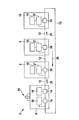
図1に概略的に示される通信構成2の実施形態は環状に形成され、直列に相前後して接続された複数の加入者、すなわち、線の区間12を介して互いに接続されたマスタ4と、第1のスレーブ6と、第2のスレーブ8と、n番目のスレーブ10と、を含む。さらに、マスタは、データパケットを送信するための第1のデジタル直列インタフェース14を備え、当該インタフェースによって、マスタ4は、定義にしたがって、線の先頭と終わりに接続される。さらに、マスタ4は、データパケットを受信するための第2のデジタル直列インタフェース16を備え、当該インタフェースによって、マスタ4は、定義にしたがって、線の先頭および終わりに接続される。その際に、第1の直列インタフェース14はシステムクロック18と接続される。第2の直列インタフェース16は、位相位置を検出するモジュール20(いわゆる遅延ロックループ、Delay Locked Loop)と接続される。さらに、マスタ4は水晶発振器22と接続される。
The embodiment of the communication arrangement 2 schematically shown in FIG. 1 is formed in a ring and is connected to a plurality of subscribers connected in series, ie a master 4 connected to each other via a
各スレーブ6、8、10は、スレーブインタフェース24として形成されたデジタル直列インタフェースを有し、当該インタフェースはそれぞれ2つの接続12と、データ線と、に接続される。したがって、2つの加入者の間には1つの接続が存在する。さらに、各直列スレーブインタフェース24はクロック回復モジュール21と接続され、このクロック回復モジュール21から局所システムクロック19が導出されうる。
Each
通信構成2の加入者間の通信を提供するために、本発明の一実施形態において、マスタ4の先頭インタフェース14から出発して、ビットストリーム26を介して、データパケットとしてのメッセージが、スレーブ6、8、10のインタフェース24からインタフェース24へと連続的に伝送されることが構想される。データパケットが最後のスレーブ6,8,10、ここではn番目のスレーブ10に到達した後に、データパケットは、最後のスレーブ10のスレーブインタフェース24によって、マスタ4の最終インタフェース16へと伝達される。
In order to provide communication between subscribers of communication configuration 2, in one embodiment of the present invention, starting from the
リング型トポロジにおける通信構成2では、複数のスレーブ6、8、10、ここでは、同一の局所アドレスを有するASICが、それぞれデジタルスレーブインタフェース24を介して直列に、ここではマイクロプロセッサとして構成されたマスタ4に接続される。その際、本実施形態においては、マスタ4のみが、環状の通信構成2内での各スレーブ6、8、10の位置についての知識を有する。
In the communication configuration 2 in the ring topology, a plurality of
本発明の一実施形態において、スレーブ6、8、10として形成された、リング型トポロジにおける通信構成の加入者またはノードは、各スレーブ6、8、10が、受信されたアドレスのアドレス値、典型的に、少なくとも1つのスレーブ宛のメッセージの伝達のために設けられたデータフレームのアドレスフィール内のアドレス値を、固定値分だけ修正し次の加入者へと転送するように、構成される。その際に、アドレス値は、例えば固定値「1」分だけ減算される。アドレス値のこの種の変更は、実施形態において、他のデータパケットについても行うことが可能であり、これは、この種のデータパケットがデータフレームではなく、メッセージを有する空フレームのみを含む場合にも可能である。
In one embodiment of the present invention, a subscriber or node in a communication topology in a ring topology, formed as
データパケットのデータ信号からクロック情報を回復するための符号化方法は、パリティビットを等間隔に挿入することにより、固定の時間内にビットストリーム26内に少なくとも1回のエッジ変更が含まれることが保障されるように行われる。連続的なデータ伝送により、通信構成2内でのスレーブ6、8、10の同期化が保障されうる。他の適切な符号化方法も適用されうる。
An encoding method for recovering clock information from a data signal of a data packet may include at least one edge change in the
データパケットは、マスタ4からスレーブ6へと伝送され、スレーブ6からスレーブ8へと次々と伝送されて最後のスレーブ10に伝送され、最後のスレーブ10からマスタ4へと伝送される。したがって、データパケットは、通信構成2の全加入者を通過する。少なくとも1つのスレーブ6、8、10へとメッセージが伝達されるデータフレームは、アドレスを含むアドレスフィールドを有する。各スレーブが、伝達すべきメッセージを有する受信されたデータフレームのアドレス値を、例えば減算または加算によって固定値の分だけ変更し、次の加入者へと転送することが構想される。ここでは、アドレス値は、各スレーブによって、そのために定めされたアルゴリズムにしたがって同じやり方で変更される。示される通信構成2内では、スレーブ6、8、10は、同一の局所アドレスを有する。さらに、全スレーブにおいて、通信インタフェースのための同一のアルゴリズムが保存される。その際に、典型的に、チップ間通信のためのモジュールのみが同一であり、それ以外は、加入者は非常に様々な機能を備えうる。
The data packet is transmitted from the master 4 to the slave 6, sequentially transmitted from the slave 6 to the slave 8, transmitted to the
以下に記載されるデータフレームまたは空フレームは例示的な構成を示す。データブロック間にさらなるビットを配置し、または、データフレーム内のブロックの構成を交換することが可能である。 The data frame or empty frame described below shows an exemplary configuration. It is possible to place further bits between the data blocks or to exchange the configuration of the blocks in the data frame.
図2に示される、本発明に係る方法の一実施形態において伝送されるデータパケット30のための例は、先頭に、第1のインターフレームシンボル(Interframe−Symbol、IFSまたは中間フレームシンボル32)と、最後に、第2の中間フレームシンボル34と、を含む。典型的に同一のこれら2つの中間フレームシンボルの間には、データパケット30内に、データフレーム36が配置される。データフレーム36の先頭に、当該データフレームは、第1の中間フレームシンボル32の後に、どの種類のデータパケット30が周回しているのかについて情報を与える予約標識38を有する。図2では、実施形態において、予約標識38が例えば値「0」を有し、したがってフレームがデータフレーム36として構成されるということが構想される。予約標識38の後に、データフレーム36は、アドレスについてのアドレス値を有するアドレスフィールド40を含む。さらに、データフレーム36は、ここではユーザデータとして構成されたデータのような命令と、さらなるチェックサムと、パリティビットと、を含みうる本来のメッセージ42を含む。
An example for a
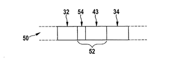
図3Aは、ここでは空フレーム52として構成されたフレームの第1の変形例を有する、データパケット50のさらなる別の例を概略的に示す。このデータパケット50も、第1の中間フレームシンボル32で始まり、第2の中間フレームシンボル34で終わる。2つの中間フレームシンボル32、34の間には空フレーム52が存在し、当該空フレーム52の場合、予約標識54が、データフレーム36を有する第1のデータパケット30に対して、値「1」を有し、したがって、フレームを空フレーム52として分類する。さらに、この空フレーム52も同様に、アドレス値を含むアドレスフィールド43を含む。ただし、ここで示される空フレーム52の実施形態およびデータパケット50は、メッセージ、したがってユーザデータを有さない。
FIG. 3A schematically shows yet another example of a
図3Aに示すようなデータパケット50によって、マスタはスレーブに連続的に、ポーリングを実行するための空フレーム52を送信する。各スレーブは、この種のデータパケット50内にデータを挿入し、および/または、少なくとも1つの要求(「ソフト割込み」)をマスタへと送信しうる。このことは典型的に、スレーブが予約標識54、通常では予約ビットを反転させ、アドレス値を「111・・・1」に設定するという形で行われる。予約標識54の活性化により、フレームは、後続の加入者について、データフレームに対応して遮断される。さらに、各後続の加入者は、図2のデータフレームの場合の手続きに対応して、固定のデータ値分だけアドレス値を修正する。したがって、データパケット50はマスタまで転送され、マスタは、アドレス情報を用いて、どのスレーブが割込み要求を出したのかを逆算することができる。
By the
図3Bに概略的に示されるデータパケット56の第3の例も同様に、第1の中間フレームシンボル32と、最後に、第2の中間フレームシンボル34と、を含む。さらに、データパケット56は、ここでは空フレーム58の第2の変形例として構成されたフレームを有する。この空フレーム58は、当該フレームを空フレーム58として定める値「1」を有する予約標識54を含む。さらに、空フレーム58は、ここではユーザデータとして構成されたデータを含むメッセージ60と、アドレス値を有するアドレスフィール43と、を含む。
The third example of the
この空フレーム58には、スレーブによって、マスタの情報のためのデータを割り当てることが可能であり、その際、予約標識54が設定される。空フレーム58内のアドレスフィールド43のアドレスのアドレス値は、最大値「111・・・1」に設定される。このことは、空フレーム58内のアドレス値がスレーブによって「111・・・1」に設定され、各後続スレーブにおけるデータフレームのアドレスフィールド内のアドレスの減算または加算によりマスタへと伝達されるように、行われる。値「111・・・1」へとアドレスを設定することは、例えば、OR結合によって、全アドレスビットが「1」で書き換えられることで行われ、その際に、空フレーム58のアドレスフィールド43は、ランダムデータを含みうる。メッセージを介して、スレーブにとって、空フレーム58により設定されたデータ長を超えないユーザデータの、直接的な伝送が可能となる。アドレスの設定されたアドレス値に対して行われる修正の数は、後続スレーブの数に対応する。したがって、マスタは、どのスレーブが空フレーム58にデータを割り当て、アドレスフィールド43を新たに設定したのかを確認することができる。
Data for master information can be assigned to the
図3Cに示されるデータパケット62の第4の例は、第1の中間フレームシンボル32および第2の中間フレームシンボル34の他に、空フレーム64として構成され、ここでは空フレーム64の第3の変形例として構成されたフレームを含む。この場合にも、フレームの種類は、ここでは値「1」を有する予約標識54により、空フレーム64として定められる。さらに、空フレーム64は、さらなるビットとして、第1のスレーブに割り当てられた第1の割込みビット66と、第2のスレーブに割り当てられた第2の割込みビット68と、第3のスレーブに割り当てられた第3の割込みビット70と、n番目のスレーブに割り当てられたn番目の割込みビット72と、を含む。
The fourth example of the data packet 62 shown in FIG. 3C is configured as an
したがって、データパケット62内では、中間フレームシンボル32および予約標識54の後に、通信構成の各スレーブについての割込みビット66、68、70、72として構成されたビットが続く。スレーブによって割込みが作動されるべきである場合には、当該スレーブによって、当該スレーブに割り当てられた割込みビット66、68、70、72が作動される。この実施形態では、割込みビット66、68、70、72の順序は、通信構成に沿ったスレーブの順序に対応し、その際、割込みビットの順序は、必ずしも通信構成に沿った順序と連携している必要はない。
Thus, in data packet 62,
図3Dに示される、データパケット74の第5の例のための実施形態も同様に第1の中間フレームシンボル32で始まり、第2の中間フレームシンボル34で終わる。さらに、データパケットは、ここでは値「1」を有し当該データパケット74のフレームを空フレーム76として定める予約標識54を有する。さらに、空フレーム76は、さらなるビットとして、可変的な数の割込みビット80、82、84を含み、すなわち、n−1番目のスレーブのためのn−1番目の割込みビット80と、通信構成の第1のスレーブのための第1の割込みビット82を含む。さらに、図3Dは、追加的に挿入されたn番目のスレーブのためのn番目の割込みビット78を示す。さらに、この空フレームの変形例は、x番目の割込みビット84を含む。
The embodiment for the fifth example of the
空フレーム76内でn番目のスレーブによりn番目の割込みビット78を挿入した後の、空フレーム76内での割り込みビット80、82、84の移動は、ここでは、矢印86で示される。したがって、空フレーム76内では、予約標識54の後ろの割込みビット78、80、82、84の順序が、各スレーブによって1ポジション分ずらされ、新しい割込みビット78が挿入されうる。マスタによって本来送信された空フレーム76はユーザデータを含まない。提供される割込みビット78、80、82、84の数は、通信構成内のスレーブの数よりも大きくまたは当該スレーブの数と等しい。割込みを作動すべき限りにおいて、この割込みは、n番目のスレーブにより挿入されたn番目の割込みビット78によって設定されうる。割込みを作動すべきではない限りにおいて、同様に、ビットが挿入されるがこれは設定されない。原則的に、提供される割込みビットの数は、通信構成内のスレーブの数よりも小さく実現することも可能であろう。ただし、全てのスレーブが割込みビットを設定できるわけではない。この場合、接続されるスレーブの通信モジュールは様々に実現されまたは少なくとも様々に構成されるが、好ましい解決策ではない。
The movement of the interrupt
図2、図3Aおよび図3Bに示されるデータパケット30、50、56の各実施形態は、アドレスフィールド40、43を有し、このアドレスフィールド40、43の構造、通常ではアドレス値の構造を介して、データパケット30、50、56が、図1に示される通信構成2の実施形態のマスタ4により、i番目のスレーブ6、8、10宛てにアドレス指定され、またはi番目のスレーブ6、8、10により、マスタ4宛てにアドレス指定されうる。
Each embodiment of the
上記のアドレスフィールド40、43の構造は、実施形態においてN個のビットを有する。N個のビットとして提示可能な最大2進値は、加入者の数、典型的にスレーブ6、8、10の数n以上である必要がある。本発明に係る方法の一実施形態において、送信されるデータパケット30、50、56が、i番目のスレーブ6、8、10に宛てられ、その際、マスタ4によりアドレスフィールドに2進数iが割り当てられることが構想される。
The structure of the address fields 40, 43 described above has N bits in the embodiment. The maximum binary value that can be presented as N bits needs to be greater than or equal to the number of subscribers, typically the number n of
このデータパケット30、50、56は、マスタ4によってスレーブ6、8、10へと送信され、データパケットが通過するi番目のスレーブ6、8、10までの各スレーブ6、8、10は、データフレームのアドレスフィールド内のアドレス値を、固定値分、例えば値「1」分だけ修正し、例えば減算する。減算の際に桁あふれが生じない限りにおいて、アドレス値は「00・・・0」でなかったのであり、これにより、アドレス値の構造を検査しているスレーブ6、8、10に対して、データパケットが当該スレーブのために定められていないことがシグナリングされる。i番目のスレーブ6、8、10に到達すると直ぐに上記の桁あふれが生じ、i番目のスレーブ6、8、10は、受信されたデータフレームが処理されうること、すなわち、通常では、データパケット30、50、56の内容、例えばメッセージ42、60が、当該i番目のスレーブ6、8、10のために定められているということを検知する。
The
インタフェースの代替的な構成において、一構成におけるアドレス値はn個のビットを有する。したがって、n個のスレーブ6、8、10それぞれについて、アドレス値の1ビットが設けられる。本発明に係る方法の一実施形態において、送信されるデータパケット30、50、56が、i番目のスレーブ6、8、10へと宛てられることが構想される場合に、マスタ4によって、アドレス値のi個の最下位ビットがそれぞれ設定され、n−i個の最上位ビットは設定されない。代替的に、i個の最上位ビットが設定されn−i個の最下位ビットが設定されないということも可能である。
In an alternative configuration of the interface, the address value in one configuration has n bits. Accordingly, one bit of the address value is provided for each of the
このデータパケット30、50、56は、マスタ4によりスレーブ6、8、10へと送信され、データパケット30、50、56が通過するi番目のスレーブ6、8、10までの各スレーブ6、8、10はその都度、設定されたビットをクリアし、したがって修正する。i番目のスレーブ6、8、10にデータフレーム36が到着した際には、全てのビットがクリアされ、すなわち設定されず、したがって、i番目のスレーブ6、8、10に対して、データパケット30、50、56、通常ではデータパケット30、50、56の内容、例えばメッセージ42、60が、当該i番目のスレーブ6、8、10のために定められていることがシグナリングされる。
The
したがって、データパケット30、50、56がそのために設けられまたは定められたi番目のスレーブ6、8、10は、アドレス値のために桁あふれを生じさせる。桁あふれ、および/または、桁あふれにより生成されるアドレス値の構造によって、i番目のスレーブ6、8、10に対して、データパケット30、50、56が当該i番目のスレーブに宛てられているということがシグナリングされる。通信構成の後続の加入者、すなわち、少なくとも1つのスレーブ6、8、10または場合によってはマスタ4へのデータパケット30、50、56の転送の前に、このi番目のスレーブ6、8、10によって、アドレスフィールド40、43のアドレス値のN個のビットが全て同一の値に設定され、例えば、全てのビットが「1」に設定されまたは全てのビットが「0」に設定される。n−i個の後続のスレーブ6、8、10は、データパケット30、50、56を既に獲得した他のi個のスレーブ6、8、10と同様に、アドレスフィールド40、43の新たに設定されたアドレス値を修正する。したがって、新たに設定されたアドレス値は、n−i回修正される。同一のデータパケットを再び獲得するマスタ4は、アドレス値の構造に基づいて、すなわち、修正されたビットの数を用いて、このアドレス値がn−i回修正されたことを検知する。これにより、マスタ4に、データパケット30、50、56がi番目のスレーブ6、8、10により処理されたことが示される。
Thus, the i-
i番目のスレーブ6、8、10が、データパケット50、56の空フレーム52、58に、マスタ4のための情報を割り当てる場合には、このi番目のスレーブ6、8、10は、アドレスフィールド43のアドレス値を同様に新たに設定する。この場合にも、マスタ4は、当該マスタ4のために設けられた情報を有するデータパケット50、56を獲得し次第、アドレス値の構造を用いて、当該アドレス値がn−i個の後続のスレーブ6、8、10によりn−i回修正されたこと、および、情報がi番目のスレーブ6、8、10に由来することを検知することができる。
When the i-
トークンとも称しうる予約標識38、54は、データパケット30、50、56、62、74がデータフレーム36(予約標識=「0」)または、空フレーム52、58、64、76(予約標識=「1」)を有するかどうかを定める。定義にしたがって、予約標識38、54のビット値も交換されうる。設定されまたは設定されていない予約標識38、54を、割り当てられたまたは空いたトークンとして見なすことも可能である。
The
図1の通信構成2は、車両内で、車両の制御装置内のマイクロコントローラとASICとの間でデータパケット30、50、56、62、74を伝送するように、構成されてもよく、その際、制御装置は通信構成2の加入者を有する。
Communication configuration 2 of FIG. 1 may be configured to transmit
通信構成の優先制御のためのプロトコルは、各スレーブが要求(「ソフト割込み」)をマスタへと伝送しうるように、実行されるが、このことがここでは図3A、図3B、図3Cおよび図3Dを用いて記載された。したがって、各スレーブに、通信インタフェースの同一のアルゴリズムが保存され、マスタは、スレーブとして構成された加入者の位置に関する知識に基づいて対応して割込みを割り当て、および、所望の優先順位にしたがって、図3Cおよび図3Dに対応するデータパケットでの複数の割込み要求の伝送が可能な場合には、処理することができる。優先制御のためのプロトコルにより、少なくとも1つのスレーブによって、空フレームを含むデータパケットを介して、マスタに対する要求が伝送されうる。 The protocol for priority control of the communication configuration is implemented so that each slave can transmit a request (“soft interrupt”) to the master, which is here shown in FIGS. 3A, 3B, 3C and Described using FIG. 3D. Therefore, the same algorithm of the communication interface is stored in each slave, the master correspondingly assigns interrupts based on the knowledge of the location of the subscriber configured as a slave, and according to the desired priority If transmission of multiple interrupt requests in data packets corresponding to 3C and 3D is possible, it can be processed. According to the protocol for priority control, a request to the master can be transmitted by at least one slave via a data packet including an empty frame.
信号からクロック情報を回復するための符号化は、パリティビットが等間隔にデータフレームに挿入され、したがって、伝送されたビットストリームが、固定の時間内に少なくとも1回のエッジ変更を有するように、行うことが可能である。 The encoding to recover the clock information from the signal is such that the parity bits are inserted into the data frame at regular intervals, so that the transmitted bit stream has at least one edge change within a fixed time. Is possible.
マスタがアイドル状態にあるときにスレーブから情報を受信しうるために、マスタは、スレーブへの問い合わせ(ポーリング)を実施するために、連続的に空フレームを送信する。各スレーブは、空フレームにデータを割り当て、および、当該データ、および/または、いわゆる「ソフト割込み」、したがって、フトウェアの割り込みとしての少なくとも1つの要求を、例えば第2レベル割込みハンドラ(SLIH)によって、すなわち、OSI参照モデルによる第2層の割込みのための制御プログラムによって、問い合わせに対する応答として、マスタへと伝達することが可能である。 In order to be able to receive information from the slave when the master is in an idle state, the master continuously sends empty frames to perform an inquiry (polling) to the slave. Each slave assigns data to an empty frame and / or the data and / or so-called “soft interrupt” and thus at least one request as a software interrupt, eg by a second level interrupt handler (SLIH) That is, it is possible to transmit to the master as a response to the inquiry by the control program for the second layer interruption by the OSI reference model.
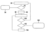
図4に示されるフロー図は、本発明に係る方法のさらなる別の実施形態における例えば環状の通信構成内の加入者としてのn個のスレーブによる、マスタにより送信されるデータフレームのアドレスフィールド内のアドレスのアドレス値の処理の例を示す。ここでは、リングにおける各スレーブでのデータ伝送の際に、アドレス指定が実現される。 The flow diagram shown in FIG. 4 shows in a further alternative embodiment of the method according to the invention in the address field of a data frame transmitted by a master, for example by n slaves as subscribers in a circular communication arrangement. An example of address value processing of an address is shown. Here, addressing is realized at the time of data transmission by each slave in the ring.
さらに、中間フレームシンボルの検出90によって、到着するデータパケットの受信が証明される。その後、検査92で、データパケットのフレームの予約標識が値1または0を有するかどうかが検査される。
In addition, the
予約標識が設定されていない場合には、受信されるデータパケットは、空フレームの変形例を有する。この場合には、i番目のスレーブによって、必要な場合には割込み94が、したがってマスタに対する要求および/または問い合わせが作動されうる。したがって、i番目のスレーブにとっては、マスタにより転送されるメッセージを有する受信されたデータパケットを埋める可能性が生まれる。 If the reservation indicator is not set, the received data packet has a variation of an empty frame. In this case, the i th slave may trigger an interrupt 94 if necessary and thus a request and / or inquiry to the master. Thus, for the i-th slave, there is a possibility to fill the received data packet with the message transferred by the master.
そうでなければ予約標識が設定されているため、データパケットはデータフレームを含む。この場合には、アドレスフィールドの処理または修正が行われる。このアドレス値ADDR[1・・・N]は、この構成において、N個のビット、または、N個の場所を有する。ここでは、N個のビットからなる最大2進数は、少なくとも、通信構成内のスレーブの数nに対応する。 Otherwise, since the reservation indicator is set, the data packet includes a data frame. In this case, the address field is processed or modified. This address value ADDR [1... N] has N bits or N locations in this configuration. Here, the maximum binary number composed of N bits corresponds to at least the number n of slaves in the communication configuration.
アドレスフィールドの修正のために、ステップ96では、変数iに値「1」が割り当てられる。
In
その後、受信されたデータフレームのアドレスフィールドADDR[1・・・N]のアドレスビットADDR[1]の反転98が行われる。最下位ビットが先頭にあるアドレスが伝送されるので、ADDR[1]の反転は、アドレス値からの「1」の減算に相当する。
Thereafter,
処理における次のステップ100で、値「1」への反転98の結果が検査される。値ADDR[1]が「1」ではなく、すなわち、値が「0」である限りにおいて、減算の際に桁あふれが生じない。この場合には、スレーブは、アドレスが今正に修正されたデータパケットを、次のi+1番目のスレーブへとさらに移動させる。スレーブによるさらなる処理は必要ないため、このスレーブは、本方法に対応して、中間フレームシンボルの新たな検出90を待ち、その間受信されたビットを変更することなくさらに移動させる。
In the
ステップ100での検査において、ADDR[1]が値「1」を有することが判明した場合には、減算の際に桁あふれが生じる。スレーブは、ステップ102において、長さNのアドレスフィールド全体が既にみられた(durchlaufen)かどうか検査する必要がある。そうではない限りにおいて、変数iは値「1」分だけ増分される(ステップ104)。引き続いて、次に高いビットの反転98が行われる。
If it is determined in
反転されたアドレスビットが「0」となるまで、アドレスフィールドの後続ビットについてループが実行される。桁あふれが生じず、すなわち、全アドレスフィールドが未だにみられていない限りにおいて、スレーブに対して、受信されたデータパケットが当該スレーブのために定められていなかったことがシグナリングされ、このスレーブはステップ90に戻って、次のデータパケットの可能な処理を続行するために、次に到着する中間フレームシンボルを待つ。しかし、桁あふれが生じ、アドレスフィールドの全ての場所が設定され、すなわち、「11・・・1」を有する限りにおいて、スレーブに対して、データパケットが当該スレーブのために定められ、処理される必要があることがシグナリングされる。この場合には、ステップ102で問い合わせが行われ、それによれば、変数iは値2N−1(最大で提示可能な、N個のビットから成る値)に相当し、および、アドレスフィールドの全ビットが反転されたのである。アドレスフィールドの評価の結果がステップ106であり、このステップ106では、受信されたデータパケット30のフレームがデータフレーム36であってi番目のスレーブのために定められ、このi番目のスレーブがデータパケット30内のこのデータフレーム36を受信する、ということが確認される。その後、i番目のスレーブによって、メッセージ42内の命令の評価、および、メッセージ42のデータの処理が行われる。
A loop is performed for subsequent bits in the address field until the inverted address bit is “0”. As long as no overflow has occurred, i.e. all address fields have not yet been seen, the slave is signaled that the received data packet has not been defined for that slave, Returning to 90, it waits for the next arriving intermediate frame symbol to continue possible processing of the next data packet. However, as long as an overflow occurs and all locations in the address field are set, i.e., have "11 ... 1", for a slave, a data packet is defined and processed for that slave. The need is signaled. In this case, an inquiry is made at
フロー図で示されるステップは、例えば、カウンタ、インバータによって、スレーブ、または、スレーブの構成要素としてのコンパレータを用いて行われうる。本方法の示される実施形態において、減数は「1」により設定された。通常では、他の固定値によるアドレスフィールドの修正のための減算または加算の他の実行も可能である。 The steps shown in the flow diagram can be performed, for example, by a counter, an inverter, a slave, or a comparator as a slave component. In the illustrated embodiment of the method, the decrement was set by “1”. Usually, other subtractions or additions for correction of the address field with other fixed values are possible.
図5は、ブロック同期型スクランブラ110の一実施形態のブロック図を示す。このブロック同期型スクランブラ110は、送信加入者としてのマスタ114(μC)内に配置された第1のm系列発生器112と、n個のm系列発生器116と、を含み、その際に、ここでは、i番目のスレーブ118(ASIC)内のi番目のn系列発生器が示される。マスタ114と、n番目のスレーブ118との間で、ビットストリーム122でのデータパケットの符号化伝送120が行われる。この場合に、伝送区間120は、さらなる加入者を含みうる。さらに、各スレーブにおいて、メッセージが最初にm系列発生器116を介して複号され、引き続いて、さらなる別の、可能な場合には異なるm系列発生器112によって新たに符号化されること、すなわち、2つの加入者間の伝送区間120がその都度符号化されることも可能である。この場合には、伝送区間120はさらなる加入者を含まない。さらに、ビットストリームの選択された部分、典型的にユーザデータのみが廃棄されることも可能である。
FIG. 5 shows a block diagram of one embodiment of a block
既に言及したスペクトル拡散の可能性の他に、ブロック同期型スクランブラ110を利用するというオプションが存在する。ブロック同期型スクランブラ110の場合、送信加入者、ここではマスタ114内データと、受信加入者、ここではi番目のスレーブ118内のデータと、に対して同時にm系列モジュロ2加算が行われ(m−Sequenz−modulo−2−addiert)、その後、2による除算の余りが加算される。
In addition to the spread spectrum possibilities already mentioned, there is an option to use the block
通常では、連続的なビットストリームの場合の、送信加入者内および受信加入者内でのブロック同期型スクランブラ110による、m系列の同期化の際には、全メッセージに渡る連続エラーが生じる可能性がある。対策を講じるために、本発明の範囲において、中間フレームシンボルによる同期化が利用される。ブロック同期型スクランブラ110の一構成において、データパケットのビットストリームがm系列に対応しないということが構想される。さらに、ビットストリームのm系列モジュロ加算の出力口で、m系列により中間フレームシンボルが生成されないことが可能となりうる。この符号化によって、個別の加入者宛のフレーム、通常では空フレームを符号化することも可能である一方で、他の、場合によっては安価な加入者、またはフレーム長が短い加入者は、スペクトル拡散のための符号化を含まない。さらに、様々な符号化の組み合わせが可能である。
Normally, in the case of m-sequence synchronization by the block
本発明によって、本発明の一実施形態において、環状の直列通信構成2の加入者間のデータ伝送が可能である。この通信構成2では加入者が互いに直列に接続され、データパケット30、50、56、62、74は、マスタ4として構成された加入者によって、スレーブ6、8、10として構成された加入者へと伝達され、データパケット30、50、56、62、74は、スレーブ6、8、10からスレーブ6、8、10へと伝達される。データパケット30、50、56、62、74の内容はアドレス情報を含む。このアドレス情報は、データパケット30、50、56、62、74のアドレスフィールド40、43内に配置され、アドレス値として形成されうる。本発明の同実施形態において、各スレーブ6、8、10によって、受信されたデータパケット30、50、56、62、74のアドレス値およびアドレス情報が、例えば、固定値分だけ変更される。
According to the present invention, in one embodiment of the present invention, data transmission between subscribers of the annular serial communication configuration 2 is possible. In this communication configuration 2, the subscribers are connected in series with each other, and the
その際に、データパケット30、50、56、62、74内のアドレスフィールド40、43の位置が任意であってもよいということが構想される。その後、スレーブ6、8、10によって、データパケット30、50、56、62、74の修正が行われる。各スレーブ6、8、10は、データパケット30、50、56、62、74内のアドレス値およびアドレス情報を同様に変更し、その際、各スレーブ6、8、10によって、同一の数学的演算、通常では加算または減算が行われる。さらに、全てのスレーブ6、8、10は、本発明の実施形態において同一のアドレスを有する。
In that case, it is envisaged that the position of the address fields 40, 43 in the
Claims (9)
データパケット(30、50、56、62、74)が、マスタ(4)として構成された加入者によって、スレーブ(6、8、10)として構成されたさらなる別の加入者へと伝達され、
前記データパケット(30、50、56、62、74)が、スレーブ(6、8、10)からスレーブ(6、8、10)へと伝達され、
各スレーブ(6、8、10)によって、前記データパケット(30、50、56、62、74)のアドレス情報が変更され、
アドレス情報として、受信された前記データパケット(30、50、56、62、74)のアドレス値が、各スレーブ(6、8、10)によって固定値分だけ変更され、
前記データパケット(30、50、56、62、74)のアドレスフィールドの構造が各スレーブ(6、8、10)により検査され、スレーブ(6、8、10)によって、前記データパケット(30、50、56、62、74)の内容が前記スレーブ(6、8、10)のために設けられているのかが前記アドレスフィールドの前記構造を用いて検知され、前記データパケット(30、50、56、62、74)が自身のために定められたスレーブ(6、8、10)が、前記アドレス値の桁あふれを生じさせる、方法。 A method for transmitting data between subscribers in a cyclic serial communication configuration (2) in which subscribers are connected in series,
A data packet (30, 50, 56, 62, 74) is transmitted by a subscriber configured as a master (4) to yet another subscriber configured as a slave (6, 8, 10);
The data packet (30, 50, 56, 62, 74) is transmitted from the slave (6, 8, 10) to the slave (6, 8, 10);
The address information of the data packet (30, 50, 56, 62, 74) is changed by each slave (6, 8, 10) ,
As address information, the address value of the received data packet (30, 50, 56, 62, 74) is changed by a fixed value by each slave (6, 8, 10),
The structure of the address field of the data packet (30, 50, 56, 62, 74) is checked by each slave (6, 8, 10), and the data packet (30, 50) is checked by the slave (6, 8, 10). , 56, 62, 74) is provided for the slave (6, 8, 10) using the structure of the address field, and the data packet (30, 50, 56, 62, 74) A slave (6, 8, 10), defined for itself, causes an overflow of the address value .
加入者がマスタ(4)として構成され、および、さらなる別の加入者がスレーブ(6、8、10)として構成され、
前記マスタ(4)は、データパケット(30、50、56、62、74)を前記スレーブ(6、8、10)へと伝達するように構成され、
各スレーブ(6、8、10)は、前記データパケット(30、50、56、62、74)を後続のスレーブ(6、8、10)へと伝達し、
各スレーブ(6、8、10)は、受信された前記データパケット(30、50、56、62、74)のアドレス情報を変更するように構成され、
各スレーブ(6、8、10)は、アドレス情報として、受信された前記データパケット(30、50、56、62、74)のアドレス値を固定値分だけ変更し、
各スレーブ(6、8、10)は、前記データパケット(30、50、56、62、74)のアドレスフィールドの構造を検査し、前記アドレスフィールドの前記構造を用いて、前記データパケット(30、50、56、62、74)の内容が前記スレーブ(6、8、10)のために設けられているのかを検知するよう構成され、前記データパケット(30、50、56、62、74)が自身のために定められたスレーブ(6、8、10)が、前記アドレス値の桁あふれを生じさせるように構成される、通信構成。 A communication configuration formed in a ring shape having a plurality of subscribers connected in series with each other,
The subscriber is configured as a master (4), and yet another subscriber is configured as a slave (6, 8, 10);
The master (4) is configured to communicate data packets (30, 50, 56, 62, 74) to the slaves (6, 8, 10);
Each slave (6, 8, 10) communicates the data packet (30, 50, 56, 62, 74) to the subsequent slave (6, 8, 10);
Each slave (6, 8, 10) is configured to change the address information of the received data packet (30, 50, 56, 62, 74) ;
Each slave (6, 8, 10) changes the address value of the received data packet (30, 50, 56, 62, 74) by a fixed value as address information,
Each slave (6, 8, 10) examines the structure of the address field of the data packet (30, 50, 56, 62, 74) and uses the structure of the address field to use the data packet (30, 50, 56, 62, 74) configured to detect whether the contents of the slave (6, 8, 10) are provided, and the data packet (30, 50, 56, 62, 74) A communication arrangement in which slaves (6, 8, 10) defined for themselves are configured to cause an overflow of the address value .
Applications Claiming Priority (2)
| Application Number | Priority Date | Filing Date | Title |
|---|---|---|---|
| DE102010041427A DE102010041427A1 (en) | 2010-09-27 | 2010-09-27 | Method for transmitting data |
| DE102010041427.1 | 2010-09-27 |
Publications (3)
| Publication Number | Publication Date |
|---|---|
| JP2012075103A JP2012075103A (en) | 2012-04-12 |
| JP2012075103A5 JP2012075103A5 (en) | 2014-11-13 |
| JP5852382B2 true JP5852382B2 (en) | 2016-02-03 |
Family
ID=44872162
Family Applications (1)
| Application Number | Title | Priority Date | Filing Date |
|---|---|---|---|
| JP2011208625A Active JP5852382B2 (en) | 2010-09-27 | 2011-09-26 | Data transmission method |
Country Status (6)
| Country | Link |
|---|---|
| US (2) | US8885645B2 (en) |
| EP (2) | EP2587740A3 (en) |
| JP (1) | JP5852382B2 (en) |
| KR (1) | KR101856222B1 (en) |
| CN (1) | CN102420736B (en) |
| DE (1) | DE102010041427A1 (en) |
Families Citing this family (42)
| Publication number | Priority date | Publication date | Assignee | Title |
|---|---|---|---|---|
| DE102011083474A1 (en) * | 2011-09-27 | 2013-03-28 | Robert Bosch Gmbh | Method for operating a communication arrangement |
| DE102011083476A1 (en) * | 2011-09-27 | 2013-03-28 | Robert Bosch Gmbh | Communication arrangement with multichannel logical communication over a physical transmission link for serial interchip data transmission |
| US10649948B2 (en) * | 2011-10-05 | 2020-05-12 | Analog Devices, Inc. | Two-wire communication systems and applications |
| US10311010B2 (en) | 2011-10-05 | 2019-06-04 | Analog Devices, Inc. | Two-wire communication systems and applications |
| US9448959B2 (en) * | 2012-10-05 | 2016-09-20 | Analog Devices, Inc. | Two-wire communication protocol engine |
| DE102012205160A1 (en) | 2012-03-29 | 2013-10-02 | Robert Bosch Gmbh | Communication arrangement and method for configuring programmable hardware |
| DE102012205163A1 (en) | 2012-03-29 | 2013-10-02 | Robert Bosch Gmbh | Communication arrangement and method for debugging or for programming one or more participants of the communication arrangement |
| US9294300B2 (en) * | 2012-04-09 | 2016-03-22 | Atmel Corporation | Token based communication in daisy chain configured battery management devices |
| US8817892B2 (en) | 2012-05-07 | 2014-08-26 | Tesla Motors, Inc. | Redundant multistate signaling |
| JP5469205B2 (en) * | 2012-06-26 | 2014-04-16 | ファナック株式会社 | Master device that changes data communication speed according to the number of slave devices |
| US10356228B2 (en) * | 2012-10-10 | 2019-07-16 | General Electric Company | Systems, methods, and apparatus for controlling power semiconductor devices |
| US9952995B2 (en) | 2012-11-27 | 2018-04-24 | Nxp Usa, Inc. | Redundant packet forwarding system |
| DE102012224060A1 (en) | 2012-12-20 | 2014-06-26 | Robert Bosch Gmbh | Method for data transmission for a battery management system |
| DE102013208183A1 (en) | 2013-05-03 | 2014-11-20 | Robert Bosch Gmbh | Method for operating at least one subscriber of a communication arrangement |
| DE102013212016A1 (en) | 2013-06-25 | 2015-01-08 | Robert Bosch Gmbh | Method for operating a communication arrangement |
| DE102013211984A1 (en) | 2013-06-25 | 2015-01-08 | Robert Bosch Gmbh | Method for operating a communication arrangement |
| DE102013212008A1 (en) | 2013-06-25 | 2015-01-08 | Robert Bosch Gmbh | Method for operating a communication arrangement |
| DE102013211988A1 (en) | 2013-06-25 | 2015-01-08 | Robert Bosch Gmbh | Method for operating a communication arrangement |
| DE102013211999A1 (en) | 2013-06-25 | 2015-01-08 | Robert Bosch Gmbh | Method for operating a communication arrangement |
| DE102013212020A1 (en) | 2013-06-25 | 2015-01-08 | Robert Bosch Gmbh | Method for operating a communication arrangement |
| DE102013214288A1 (en) | 2013-07-22 | 2015-01-22 | Robert Bosch Gmbh | Method and device for data exchange in a vehicle |
| US10216678B2 (en) | 2014-10-07 | 2019-02-26 | Infineon Technologies Ag | Serial peripheral interface daisy chain communication with an in-frame response |
| DE102014117797A1 (en) | 2014-10-10 | 2016-04-14 | Ebm-Papst Mulfingen Gmbh & Co. Kg | Dynamically addressable master-slave system and method for dynamic addressing of slave units |
| KR102598056B1 (en) | 2015-02-15 | 2023-11-06 | 스카이워크스 솔루션즈, 인코포레이티드 | Circuits, devices and methods for monitoring a serial bus |
| US9788182B2 (en) * | 2015-06-03 | 2017-10-10 | The United States Of America As Represented By The Secretary Of The Army | Method and system for packet collision avoidance in a wireless communication system |
| CN105049370A (en) * | 2015-08-18 | 2015-11-11 | 北京汉柏科技有限公司 | Component communication method based on cloud computing operation system |
| JP6457417B2 (en) * | 2016-03-22 | 2019-01-23 | ファナック株式会社 | Serial communication branch device and serial communication system |
| DE202016007687U1 (en) * | 2016-11-30 | 2017-01-30 | Siemens Aktiengesellschaft | Command and message system for automation technology |
| CN108574663B (en) * | 2017-03-09 | 2021-08-13 | 李明 | Safe transmission method and system |
| DE102017208830A1 (en) * | 2017-05-24 | 2018-11-29 | Wago Verwaltungsgesellschaft Mbh | Determination of data bus users of a local bus |
| JP6771791B2 (en) * | 2017-07-11 | 2020-10-21 | イノヴァ セミコンダクトルズ ゲーエムベーハー | Energy efficient data frame exchange |
| CN108418739A (en) * | 2018-02-09 | 2018-08-17 | 浙江大学 | A kind of token ring network-building method based on SPI |
| DE102018001574B4 (en) * | 2018-02-28 | 2019-09-05 | WAGO Verwaltungsgesellschaft mit beschränkter Haftung | Master-slave bus system and method for operating a bus system |
| US10593256B2 (en) * | 2018-03-22 | 2020-03-17 | Sct Ltd. | LED display device and method for operating the same |
| WO2019232482A1 (en) * | 2018-05-31 | 2019-12-05 | Synaptics Incorporated | Low power, high bandwidth, low latency data bus |
| CN109359073B (en) * | 2018-09-18 | 2020-10-20 | 深圳吉迪思电子科技有限公司 | Inter-device communication method and device based on SPI bus |
| US11295828B2 (en) | 2019-03-08 | 2022-04-05 | Analog Devices International Unlimited Company | Multi-chip programming for phased array |
| CN110519136B (en) * | 2019-07-10 | 2021-06-29 | 大城绿川(深圳)科技有限公司 | RS485 multi-machine communication system capable of achieving self-adaptive networking |
| FR3102584B1 (en) * | 2019-10-28 | 2021-11-05 | St Microelectronics Grenoble 2 | Bus communication acknowledgment method |
| CN114553629A (en) * | 2021-12-15 | 2022-05-27 | 中国铁路设计集团有限公司 | Rail transit road bed internet of things big data bus transmission method and system |
| KR20230099429A (en) * | 2021-12-27 | 2023-07-04 | 삼성전자주식회사 | Electronic apparatus and controlling method thereof |
| DE102022125715A1 (en) | 2022-10-05 | 2024-04-11 | Bayerische Motoren Werke Aktiengesellschaft | Method and support device for supporting robustness optimization for a data processing system and corresponding CI system |
Family Cites Families (18)
| Publication number | Priority date | Publication date | Assignee | Title |
|---|---|---|---|---|
| GB2188216A (en) | 1986-03-17 | 1987-09-23 | Plessey Co Plc | Ring bus communications systems |
| US4726018A (en) | 1986-08-25 | 1988-02-16 | International Business Machines Corporation | Method of providing priority access to a transmission communication ring |
| US5483518A (en) * | 1992-06-17 | 1996-01-09 | Texas Instruments Incorporated | Addressable shadow port and protocol for serial bus networks |
| CA2018719C (en) * | 1989-06-09 | 1993-12-21 | Hiroshi Shimizu | Token passing type slotted loop network system with means for enabling high speed access control and simple frame slot stripping |
| JP2596879Y2 (en) * | 1992-03-26 | 1999-06-21 | 松下電工株式会社 | Monitoring and control system |
| JPH0697948A (en) * | 1992-09-11 | 1994-04-08 | Fujitsu Ltd | Address setting system |
| GB9312136D0 (en) * | 1993-06-11 | 1993-07-28 | Inmos Ltd | Transmission of messages |
| JPH086885A (en) * | 1994-06-20 | 1996-01-12 | Toyo Kanetsu Kk | Control system for serial communication |
| US6222848B1 (en) * | 1997-12-22 | 2001-04-24 | Nortel Networks Limited | Gigabit ethernet interface to synchronous optical network (SONET) ring |
| DE19803686A1 (en) | 1998-01-30 | 1999-08-05 | Siemens Ag | Method and device for the communication of equal stations of a ring-shaped, serial optical fiber bus |
| GB2338155B (en) * | 1998-06-05 | 2003-02-12 | 3Com Technologies Ltd | Hub system with ring arbitration |
| CN100426782C (en) * | 2004-08-11 | 2008-10-15 | 中兴通讯股份有限公司 | Method for transmitting singlecast service in resilient packet ring |
| DE102005056294B4 (en) * | 2005-11-24 | 2016-04-28 | Sew-Eurodrive Gmbh & Co Kg | Method for assigning addresses to bus users of a bus system and system |
| JP5036041B2 (en) * | 2007-04-25 | 2012-09-26 | アズビル株式会社 | RSTP processing method |
| JP5115033B2 (en) * | 2007-05-30 | 2013-01-09 | 富士通株式会社 | Packet relay method and apparatus |
| US8594110B2 (en) * | 2008-01-11 | 2013-11-26 | Mosaid Technologies Incorporated | Ring-of-clusters network topologies |
| JP2009194731A (en) * | 2008-02-15 | 2009-08-27 | Fujitsu Ltd | Slave device, and system and method for data transmission |
| US9021292B2 (en) * | 2011-05-20 | 2015-04-28 | Texas Instruments Incorporated | Method and system for asynchronous serial communication in a ring network by generating an oversampling clock using a fractional rate multiplier and sampling a received data bit sequence that includes voltage and temperature information in a battery management system |
-
2010
- 2010-09-27 DE DE102010041427A patent/DE102010041427A1/en not_active Ceased
-
2011
- 2011-09-02 EP EP13152545.3A patent/EP2587740A3/en not_active Withdrawn
- 2011-09-02 EP EP11179828.6A patent/EP2434695B1/en active Active
- 2011-09-26 JP JP2011208625A patent/JP5852382B2/en active Active
- 2011-09-26 KR KR1020110096879A patent/KR101856222B1/en active IP Right Grant
- 2011-09-26 CN CN201110287659.6A patent/CN102420736B/en active Active
- 2011-09-26 US US13/245,311 patent/US8885645B2/en active Active
-
2014
- 2014-09-29 US US14/499,524 patent/US9252969B2/en active Active
Also Published As
| Publication number | Publication date |
|---|---|
| JP2012075103A (en) | 2012-04-12 |
| EP2587740A2 (en) | 2013-05-01 |
| DE102010041427A1 (en) | 2012-03-29 |
| US20150085864A1 (en) | 2015-03-26 |
| KR101856222B1 (en) | 2018-06-26 |
| KR20120031910A (en) | 2012-04-04 |
| EP2434695A1 (en) | 2012-03-28 |
| US20120076146A1 (en) | 2012-03-29 |
| US9252969B2 (en) | 2016-02-02 |
| CN102420736A (en) | 2012-04-18 |
| CN102420736B (en) | 2016-12-21 |
| US8885645B2 (en) | 2014-11-11 |
| EP2587740A3 (en) | 2013-12-04 |
| EP2434695B1 (en) | 2014-03-05 |
Similar Documents
| Publication | Publication Date | Title |
|---|---|---|
| JP5852382B2 (en) | Data transmission method | |
| CN110061795B (en) | Method for generating high-speed embedded protocol for distributed control system | |
| US8179787B2 (en) | Fault tolerant network utilizing bi-directional point-to-point communications links between nodes | |
| KR102116930B1 (en) | Controller area network with flexible data-rate | |
| CN103155492B (en) | Communication system and communicator | |
| JP6469365B2 (en) | Method for providing general-purpose interface and microcontroller having general-purpose interface | |
| CN106464559B (en) | High speed embedded protocol for distributed control system | |
| Berwanger et al. | FlexRay–the communication system for advanced automotive control systems | |
| JP4873663B2 (en) | Method and apparatus for decoding a signal | |
| TWI572166B (en) | Process to operate a communication device | |
| US9432488B2 (en) | High speed embedded protocol for distributed control systems | |
| US9672182B2 (en) | High-speed serial ring | |
| US8737426B1 (en) | High speed embedded protocol for distributed control system | |
| JP2004535091A (en) | Method and apparatus for synchronizing cycle times of multiple TTCAN-buses and corresponding bus system | |
| US9065732B2 (en) | Communication configuration and method for debugging, respectively for programming one or more participants of the communication configuration | |
| US20130262610A1 (en) | Communication system and method for configuring programmable hardware | |
| Specification | Bosch | |
| Kim et al. | A method for improving the reliability of the gateway system by using OSEK and duplication scheme | |
| Harish et al. | Design and verification of flexray to can protocol converter node | |
| Cena et al. | Protocols and Services in Controller Area Networks | |
| CN104253731A (en) | Method for running communication device | |
| Mahmud | Communication Networks for the Next-Generation Vehicles |
Legal Events
| Date | Code | Title | Description |
|---|---|---|---|
| A521 | Request for written amendment filed |
Free format text: JAPANESE INTERMEDIATE CODE: A523 Effective date: 20140925 |
|
| A621 | Written request for application examination |
Free format text: JAPANESE INTERMEDIATE CODE: A621 Effective date: 20140925 |
|
| A977 | Report on retrieval |
Free format text: JAPANESE INTERMEDIATE CODE: A971007 Effective date: 20150518 |
|
| A131 | Notification of reasons for refusal |
Free format text: JAPANESE INTERMEDIATE CODE: A131 Effective date: 20150526 |
|
| A521 | Request for written amendment filed |
Free format text: JAPANESE INTERMEDIATE CODE: A523 Effective date: 20150729 |
|
| TRDD | Decision of grant or rejection written | ||
| A01 | Written decision to grant a patent or to grant a registration (utility model) |
Free format text: JAPANESE INTERMEDIATE CODE: A01 Effective date: 20151104 |
|
| A61 | First payment of annual fees (during grant procedure) |
Free format text: JAPANESE INTERMEDIATE CODE: A61 Effective date: 20151204 |
|
| R150 | Certificate of patent or registration of utility model |
Ref document number: 5852382 Country of ref document: JP Free format text: JAPANESE INTERMEDIATE CODE: R150 |
|
| R250 | Receipt of annual fees |
Free format text: JAPANESE INTERMEDIATE CODE: R250 |
|
| R250 | Receipt of annual fees |
Free format text: JAPANESE INTERMEDIATE CODE: R250 |
|
| R250 | Receipt of annual fees |
Free format text: JAPANESE INTERMEDIATE CODE: R250 |
|
| R250 | Receipt of annual fees |
Free format text: JAPANESE INTERMEDIATE CODE: R250 |
|
| R250 | Receipt of annual fees |
Free format text: JAPANESE INTERMEDIATE CODE: R250 |
|
| R250 | Receipt of annual fees |
Free format text: JAPANESE INTERMEDIATE CODE: R250 |