JP5837094B2 - Snap-sealed sterile intravascular catheter dressing system - Google Patents
Snap-sealed sterile intravascular catheter dressing system Download PDFInfo
- Publication number
- JP5837094B2 JP5837094B2 JP2013551993A JP2013551993A JP5837094B2 JP 5837094 B2 JP5837094 B2 JP 5837094B2 JP 2013551993 A JP2013551993 A JP 2013551993A JP 2013551993 A JP2013551993 A JP 2013551993A JP 5837094 B2 JP5837094 B2 JP 5837094B2
- Authority
- JP
- Japan
- Prior art keywords
- catheter
- hub
- needle
- dressing assembly
- dressing
- Prior art date
- Legal status (The legal status is an assumption and is not a legal conclusion. Google has not performed a legal analysis and makes no representation as to the accuracy of the status listed.)
- Active
Links
- 238000003780 insertion Methods 0.000 claims description 82
- 230000037431 insertion Effects 0.000 claims description 82
- 230000001012 protector Effects 0.000 claims description 36
- 230000001954 sterilising effect Effects 0.000 claims description 30
- 230000007246 mechanism Effects 0.000 claims description 29
- 230000001681 protective effect Effects 0.000 claims description 27
- 239000000853 adhesive Substances 0.000 claims description 25
- 230000001070 adhesive effect Effects 0.000 claims description 25
- 238000004659 sterilization and disinfection Methods 0.000 claims description 25
- 239000012528 membrane Substances 0.000 claims description 8
- 230000004308 accommodation Effects 0.000 claims description 4
- 239000007788 liquid Substances 0.000 claims description 3
- 230000002093 peripheral effect Effects 0.000 claims 1
- 238000000034 method Methods 0.000 description 51
- 238000007789 sealing Methods 0.000 description 27
- 239000000463 material Substances 0.000 description 26
- 230000013011 mating Effects 0.000 description 15
- 239000008280 blood Substances 0.000 description 13
- 210000004369 blood Anatomy 0.000 description 13
- 238000004140 cleaning Methods 0.000 description 10
- 230000036512 infertility Effects 0.000 description 9
- 230000002792 vascular Effects 0.000 description 9
- 239000000243 solution Substances 0.000 description 7
- 210000004204 blood vessel Anatomy 0.000 description 6
- 230000000694 effects Effects 0.000 description 6
- 230000008569 process Effects 0.000 description 6
- 208000032840 Catheter-Related Infections Diseases 0.000 description 5
- 239000004033 plastic Substances 0.000 description 5
- 229920003023 plastic Polymers 0.000 description 5
- 208000015181 infectious disease Diseases 0.000 description 4
- 238000009434 installation Methods 0.000 description 4
- 238000001990 intravenous administration Methods 0.000 description 4
- 230000005855 radiation Effects 0.000 description 4
- 238000000926 separation method Methods 0.000 description 4
- 230000000844 anti-bacterial effect Effects 0.000 description 3
- 230000008439 repair process Effects 0.000 description 3
- 230000004044 response Effects 0.000 description 3
- 201000005060 thrombophlebitis Diseases 0.000 description 3
- 238000012800 visualization Methods 0.000 description 3
- 230000002411 adverse Effects 0.000 description 2
- 238000002583 angiography Methods 0.000 description 2
- 229940088710 antibiotic agent Drugs 0.000 description 2
- 230000003115 biocidal effect Effects 0.000 description 2
- 230000000740 bleeding effect Effects 0.000 description 2
- 238000011010 flushing procedure Methods 0.000 description 2
- 230000036541 health Effects 0.000 description 2
- 238000007373 indentation Methods 0.000 description 2
- 208000014674 injury Diseases 0.000 description 2
- 230000003993 interaction Effects 0.000 description 2
- 230000007774 longterm Effects 0.000 description 2
- 238000012423 maintenance Methods 0.000 description 2
- 238000012544 monitoring process Methods 0.000 description 2
- 238000002360 preparation method Methods 0.000 description 2
- 239000000047 product Substances 0.000 description 2
- 230000000284 resting effect Effects 0.000 description 2
- 230000002441 reversible effect Effects 0.000 description 2
- 239000007787 solid Substances 0.000 description 2
- 239000008174 sterile solution Substances 0.000 description 2
- 239000003206 sterilizing agent Substances 0.000 description 2
- 230000008733 trauma Effects 0.000 description 2
- 238000011282 treatment Methods 0.000 description 2
- 241000894006 Bacteria Species 0.000 description 1
- 208000035473 Communicable disease Diseases 0.000 description 1
- 229920000742 Cotton Polymers 0.000 description 1
- 238000012276 Endovascular treatment Methods 0.000 description 1
- LFQSCWFLJHTTHZ-UHFFFAOYSA-N Ethanol Chemical compound CCO LFQSCWFLJHTTHZ-UHFFFAOYSA-N 0.000 description 1
- IAYPIBMASNFSPL-UHFFFAOYSA-N Ethylene oxide Chemical compound C1CO1 IAYPIBMASNFSPL-UHFFFAOYSA-N 0.000 description 1
- 241001465754 Metazoa Species 0.000 description 1
- 229920000459 Nitrile rubber Polymers 0.000 description 1
- FAPWRFPIFSIZLT-UHFFFAOYSA-M Sodium chloride Chemical compound [Na+].[Cl-] FAPWRFPIFSIZLT-UHFFFAOYSA-M 0.000 description 1
- 239000004775 Tyvek Substances 0.000 description 1
- 229920000690 Tyvek Polymers 0.000 description 1
- 230000002745 absorbent Effects 0.000 description 1
- 239000002250 absorbent Substances 0.000 description 1
- 239000002313 adhesive film Substances 0.000 description 1
- 208000012759 altered mental status Diseases 0.000 description 1
- 239000003242 anti bacterial agent Substances 0.000 description 1
- 230000000845 anti-microbial effect Effects 0.000 description 1
- 230000000712 assembly Effects 0.000 description 1
- 238000000429 assembly Methods 0.000 description 1
- 230000009286 beneficial effect Effects 0.000 description 1
- 230000008901 benefit Effects 0.000 description 1
- 230000008859 change Effects 0.000 description 1
- 239000011248 coating agent Substances 0.000 description 1
- 238000000576 coating method Methods 0.000 description 1
- 230000001447 compensatory effect Effects 0.000 description 1
- 230000000295 complement effect Effects 0.000 description 1
- 239000002131 composite material Substances 0.000 description 1
- 230000008602 contraction Effects 0.000 description 1
- 230000008878 coupling Effects 0.000 description 1
- 238000010168 coupling process Methods 0.000 description 1
- 238000005859 coupling reaction Methods 0.000 description 1
- 230000006378 damage Effects 0.000 description 1
- 230000001419 dependent effect Effects 0.000 description 1
- 238000013461 design Methods 0.000 description 1
- 201000010099 disease Diseases 0.000 description 1
- 208000037265 diseases, disorders, signs and symptoms Diseases 0.000 description 1
- 229920001971 elastomer Polymers 0.000 description 1
- 238000005516 engineering process Methods 0.000 description 1
- 239000000835 fiber Substances 0.000 description 1
- 229920002457 flexible plastic Polymers 0.000 description 1
- 239000012530 fluid Substances 0.000 description 1
- 230000023597 hemostasis Effects 0.000 description 1
- 230000008595 infiltration Effects 0.000 description 1
- 238000001764 infiltration Methods 0.000 description 1
- 238000001802 infusion Methods 0.000 description 1
- 238000002347 injection Methods 0.000 description 1
- 239000007924 injection Substances 0.000 description 1
- 238000010253 intravenous injection Methods 0.000 description 1
- 229920000126 latex Polymers 0.000 description 1
- 239000004816 latex Substances 0.000 description 1
- 230000000670 limiting effect Effects 0.000 description 1
- 230000003340 mental effect Effects 0.000 description 1
- 239000002184 metal Substances 0.000 description 1
- 244000005700 microbiome Species 0.000 description 1
- 239000000203 mixture Substances 0.000 description 1
- 238000012986 modification Methods 0.000 description 1
- 230000004048 modification Effects 0.000 description 1
- 230000000144 pharmacologic effect Effects 0.000 description 1
- 239000002985 plastic film Substances 0.000 description 1
- 229920001296 polysiloxane Polymers 0.000 description 1
- 230000002265 prevention Effects 0.000 description 1
- 230000001737 promoting effect Effects 0.000 description 1
- 239000005060 rubber Substances 0.000 description 1
- 239000011780 sodium chloride Substances 0.000 description 1
- 238000010186 staining Methods 0.000 description 1
- 230000003068 static effect Effects 0.000 description 1
- 239000000126 substance Substances 0.000 description 1
- 239000013589 supplement Substances 0.000 description 1
- 230000000153 supplemental effect Effects 0.000 description 1
- 238000004381 surface treatment Methods 0.000 description 1
- 210000005166 vasculature Anatomy 0.000 description 1
- 239000013598 vector Substances 0.000 description 1
- 210000003462 vein Anatomy 0.000 description 1
- 230000002861 ventricular Effects 0.000 description 1
- XLYOFNOQVPJJNP-UHFFFAOYSA-N water Substances O XLYOFNOQVPJJNP-UHFFFAOYSA-N 0.000 description 1
- 230000029663 wound healing Effects 0.000 description 1
Images


Classifications
-
- A—HUMAN NECESSITIES
- A61—MEDICAL OR VETERINARY SCIENCE; HYGIENE
- A61M—DEVICES FOR INTRODUCING MEDIA INTO, OR ONTO, THE BODY; DEVICES FOR TRANSDUCING BODY MEDIA OR FOR TAKING MEDIA FROM THE BODY; DEVICES FOR PRODUCING OR ENDING SLEEP OR STUPOR
- A61M25/00—Catheters; Hollow probes
- A61M25/01—Introducing, guiding, advancing, emplacing or holding catheters
- A61M25/06—Body-piercing guide needles or the like
- A61M25/0612—Devices for protecting the needle; Devices to help insertion of the needle, e.g. wings or holders
- A61M25/0631—Devices for protecting the needle; Devices to help insertion of the needle, e.g. wings or holders having means for fully covering the needle after its withdrawal, e.g. needle being withdrawn inside the handle or a cover being advanced over the needle
-
- A—HUMAN NECESSITIES
- A61—MEDICAL OR VETERINARY SCIENCE; HYGIENE
- A61M—DEVICES FOR INTRODUCING MEDIA INTO, OR ONTO, THE BODY; DEVICES FOR TRANSDUCING BODY MEDIA OR FOR TAKING MEDIA FROM THE BODY; DEVICES FOR PRODUCING OR ENDING SLEEP OR STUPOR
- A61M25/00—Catheters; Hollow probes
- A61M25/01—Introducing, guiding, advancing, emplacing or holding catheters
- A61M25/02—Holding devices, e.g. on the body
- A61M2025/024—Holding devices, e.g. on the body having a clip or clamp system
-
- A—HUMAN NECESSITIES
- A61—MEDICAL OR VETERINARY SCIENCE; HYGIENE
- A61M—DEVICES FOR INTRODUCING MEDIA INTO, OR ONTO, THE BODY; DEVICES FOR TRANSDUCING BODY MEDIA OR FOR TAKING MEDIA FROM THE BODY; DEVICES FOR PRODUCING OR ENDING SLEEP OR STUPOR
- A61M25/00—Catheters; Hollow probes
- A61M25/01—Introducing, guiding, advancing, emplacing or holding catheters
- A61M25/02—Holding devices, e.g. on the body
- A61M2025/0246—Holding devices, e.g. on the body fixed on the skin having a cover for covering the holding means
-
- A—HUMAN NECESSITIES
- A61—MEDICAL OR VETERINARY SCIENCE; HYGIENE
- A61M—DEVICES FOR INTRODUCING MEDIA INTO, OR ONTO, THE BODY; DEVICES FOR TRANSDUCING BODY MEDIA OR FOR TAKING MEDIA FROM THE BODY; DEVICES FOR PRODUCING OR ENDING SLEEP OR STUPOR
- A61M25/00—Catheters; Hollow probes
- A61M25/01—Introducing, guiding, advancing, emplacing or holding catheters
- A61M25/02—Holding devices, e.g. on the body
- A61M2025/0266—Holding devices, e.g. on the body using pads, patches, tapes or the like
- A61M2025/0273—Holding devices, e.g. on the body using pads, patches, tapes or the like having slits to place the pad around a catheter puncturing site
Description
本願は、2011年1月31日に出願された米国特許仮出願(米国特許仮出願番号第61/437,862号)の優先権を主張するものであり、該特許仮出願の全内容を参照により本明細書に援用するものとする。本願はまた、2011年5月3日に出願された米国特許仮出願(米国特許仮出願番号第61/482,124号)の優先権を主張するものであり、該特許仮出願の全内容を参照により本明細書に援用するものとする。本願はまた、2011年5月4日に出願された米国特許仮出願(米国特許仮出願番号第61/482,564号)の優先権を主張するものであり、該特許仮出願の全内容を参照により本明細書に援用するものとする。 This application claims the priority of the US provisional application (US Patent Provisional Application No. 61 / 437,862) filed on January 31, 2011. See the entire contents of the provisional application. Is incorporated herein by reference. This application also claims the priority of a US provisional application (US provisional application No. 61 / 482,124) filed on May 3, 2011. Which is incorporated herein by reference. The present application also claims the priority of a US provisional application (US provisional application No. 61 / 482,564) filed on May 4, 2011. Which is incorporated herein by reference.
本発明は、医療機器を滅菌状態で封止し固定するための方法及び装置に関するものであって、特に血管内カテーテルを挿入し、血管内カテーテル及びその挿入部位を封止し、血管内カテーテル及びその挿入部位の滅菌状態を維持するための方法及び装置に関するものである。 The present invention relates to a method and an apparatus for sealing and fixing a medical device in a sterilized state, and in particular, an intravascular catheter is inserted, the intravascular catheter and its insertion site are sealed, and the intravascular catheter and The present invention relates to a method and an apparatus for maintaining the sterilized state of the insertion site.
医学文献でも一般紙でも、医療関連の感染症に関する一般的な問題が大きく注目されている。多剤耐性微生物の憂慮すべき増加は、医療関連の感染症の治療の裏付けのあるコストと相まって、あらゆる潜在的な感染症の経路に対処し、当該経路を取り除くことを、大きな世界的使命にさせている。これらの取り組みが一層活発になることは、米国メディケア・メディケイドサービスセンター(the United States Centers for Medicare and Medicaid Services)が、医療関連感染に関連するコストを、病院にもはや補償しないと規定することになる。すべてのカテーテル関連の感染症は、今後カバーされなくなるであろうリストアップされた有害な事象のうち、最大のものである。病院及び医療システムによる、カテーテル関連の感染症を取り除こうとする当然の強い意欲に起因して、多数の新たな方法及び製品が導入されてきた。これらの中には、抗生物質を含浸させたドレッシング材及びカテーテル、抗生物質を含浸させたドレッシング材の付属物、カテーテルのアクセスポイントの洗浄装置、及び最新の厳格なカテーテルの手入れのガイドラインの適用が含まれている。これらの試みにもかかわらず、カテーテル関連の感染症は続いている。 In the medical literature and general papers, general problems related to medical-related infectious diseases are attracting much attention. The alarming increase in multidrug-resistant microorganisms, coupled with the supporting costs of treating medical-related infections, has addressed a potential global path to addressing and removing all potential infection paths. I am letting. More active in these efforts will stipulate that the United States Centers for Medicare and Medicaid Services no longer compensate hospitals for costs associated with healthcare-related infections. . All catheter-related infections are the largest of the adverse events listed that will not be covered in the future. A number of new methods and products have been introduced due to the natural and willingness to remove catheter-related infections by hospitals and medical systems. Among these are the application of antibiotic-impregnated dressings and catheters, antibiotic-impregnated dressing accessories, catheter access point cleaning devices, and the latest strict catheter care guidelines. include. Despite these attempts, catheter-related infections continue.
あらゆる既存の血管カテーテルのドレッシング材は、皮膚に対してカテーテルを平坦に押圧する、単純なバンドエイド(登録商標)型の被覆機構に依存する。アメリカ疾病予防管理センター(the United States Centers for Disease Control and Prevention)は、このようなドレッシング材を現在2種類推奨している。1種類目はガーゼ及びテープから成り、2種類目は接着剤の付いたフィルムから成る。ドレッシング材の材料自体を最初に滅菌することができるが、カテーテルのドレッシング材の出口点で封止できないことは、ドレッシング材の滅菌状態の維持を妨げる。その結果、カテーテルのドレッシング材を、新しく清潔なドレッシング材に、頻繁な間隔で交換する必要がある。カテーテル自身も特定の間隔で除去し、新しいカテーテルを配置しなければならない。その上、カテーテルのあらゆる動きは、ドレッシング材を緩め、滅菌性の問題を悪化させる。水及び汚染流体は、カテーテル及びカテーテル挿入部位に直接接触する。カテーテルの動き及び非滅菌状態は、血栓性静脈炎等の他の合併症をも引き起こすことがある。 Any existing vascular catheter dressing relies on a simple Band-Aid® type coating mechanism that presses the catheter flat against the skin. The United States Centers for Disease Control and Prevention currently recommends two such dressings. The first type consists of gauze and tape, and the second type consists of a film with an adhesive. The dressing material itself can be sterilized first, but the inability to seal at the catheter dressing exit point prevents the dressing from maintaining sterility. As a result, it is necessary to replace the catheter dressing with a new, clean dressing at frequent intervals. The catheter itself must also be removed at specific intervals and a new catheter placed. Moreover, any movement of the catheter will loosen the dressing and exacerbate the sterility problem. Water and contaminated fluid are in direct contact with the catheter and catheter insertion site. Catheter movement and non-sterile conditions can also cause other complications such as thrombophlebitis.
感染症及び血栓性静脈炎の有害な後遺症、並びにカテーテル及びドレッシング材の交換に起因する介護者の非効率的及び患者の不快感に加えて、他の問題が現在のカテーテルシステム及びカテーテルケアシステムを苦しめ続けている。第一に、ドレッシング材の不適切な構造の根本的な問題を悪化させるものは、伝統的なカテーテル及びカテーテルのドレッシング材を配置するための手順のとてつもなく大きいばらつきである。カテーテルの配置及びケア技術は、組織の見地からも個々の介護者の見地からも、ユーザに極めて依存する。臨床上、このことは、ただでさえ意図的に根本的に不適切であるカテーテル及びドレッシング材で、血管内カテーテル及び血管内カテーテルのドレッシング材が準最適に配置される発生率を容認できないほど高くする。第二に、血管カテーテルを適切な滅菌状態の確保することが課題であり続ける。CDCが推奨する、前記2つの伝統的なパッチ型のドレッシング材は、カテーテルを部分的に固定するのみである。そして、補足的な非滅菌支持テープ、又は他の専用に適用された固定器具に依存し、不十分な滅菌状態の問題を悪化させる役目をする。患者の不注意により血管カテーテルが引き抜かれることは珍しいことではなく、重大な失血、血管アクセスの危険な喪失、及び死にさえつながることがある。 In addition to the harmful sequelae of infection and thrombophlebitis, as well as caregiver inefficiencies and patient discomfort due to catheter and dressing replacement, other problems have caused current catheter and catheter care systems to I continue to suffer. First, what exacerbates the fundamental problem of improper dressing structure is the tremendous variation in traditional catheters and procedures for placing catheter dressings. Catheter placement and care techniques are highly dependent on the user, both from a tissue and individual caregiver perspective. Clinically, this is unacceptably high in the rate of sub-optimal placement of endovascular and endovascular catheter dressings, even with catheters and dressings that are deliberately fundamentally inappropriate. To do. Second, ensuring that the vascular catheter is properly sterilized continues to be a challenge. The two traditional patch dressings recommended by the CDC only partially fix the catheter. It then relies on supplemental non-sterile support tapes or other specially applied fixation devices to serve to exacerbate the problem of inadequate sterilization. It is not uncommon for a vascular catheter to be withdrawn due to patient carelessness, which can lead to severe blood loss, dangerous loss of vascular access, and even death.
新しいドレッシング材の付属物が非常に急速に採用されているという事実は、医療工業システムによる伝統的な血管内カテーテル及びドレッシング材の不十分さの理解、及び医療工業システムによるカテーテル関連の感染症の問題に対する要求を実証している。結局のところは、しかしながら、これらの補償的な手段は、血管カテーテルの配置及び手入れに対する旧式で次善の方法を単純に補うのみの、技術的及び薬理学的手順にすぎない。明らかに、改良された、カテーテルの配置及びカテーテルのドレッシング材の装置及び技術に対する要求が存在する。 The fact that new dressing appendages are being adopted very rapidly is due to the understanding of the lack of traditional intravascular catheters and dressings by the medical industry system, and of catheter-related infections by the medical industry system. Demonstrates the demand for the problem. Ultimately, however, these compensatory means are merely technical and pharmacological procedures that simply supplement the old and suboptimal methods for vascular catheter placement and care. Clearly, there is a need for improved catheter placement and catheter dressing devices and techniques.
カテーテル関連の感染症を最小化し又は除去さえすることができ、血管カテーテルの手入れについて、健康管理の提供を著しく改良させることができる、カテーテル及びカテーテル挿入部位をドレッシングするための方法及び装置を提供する。永続的に固定され、封止され、及び滅菌された血管カテーテルの最適な挿入及びメンテナンスを可能とする、統合されたカテーテルのドレッシングシステムを提供する。これらのシステムは、滅菌済みの、封止された及び安全なドレッシング材をカテーテルに適用するため、カテーテル及びカテーテル挿入部位の滅菌状態を長期間維持するため、並びに不使用時には、人間工学的に及び滅菌的にカテーテルハブの接続位置を保護するため、カテーテルを任意の所望の経皮挿入部位に配置することができる。本明細書に記載されたカテーテルのドレッシングシステムはまた、前記システムの形態及び機能と統合する方法で、安全な挿入針の収容を提供する。ある実施形態では、システムは、(1)新規な血管カテーテル、(2)この新規なカテーテルと嵌合するように特に設計された滅菌済み封止ドレッシング材、(3)当該新規なカテーテル及び当該封止ドレッシング材の両方と嵌合するように設計された、カテーテルハブ封止装置及び滅菌装置、そして(4)一体となったカテーテルのドレッシングシステムの保護カバー、を備える。これらの4つの構成要素は一緒に、永続的に滅菌状態で、安全で、堅固な血管内カテーテルを提供するために、使いやすい、高度に再現可能な、そして完全に包括的なシステムを構築する。これらの4つの構成要素は、記載するような統合化された方法で作動できる一方、これらの4つの構成要素は、個々に又は任意の組み合わせで、既存の(又は将来の)カテーテル及びドレッシング技術とともに適用することもできる。 A method and apparatus for dressing a catheter and catheter insertion site that can minimize or even eliminate catheter-related infections and can significantly improve the provision of health care for vascular catheter care. . An integrated catheter dressing system is provided that allows for optimal insertion and maintenance of permanently fixed, sealed and sterilized vascular catheters. These systems apply sterilized, sealed and safe dressings to the catheter, maintain sterility at the catheter and catheter insertion site for long periods of time, and ergonomically when not in use. The catheter can be placed at any desired percutaneous insertion site to aseptically protect the catheter hub connection location. The catheter dressing system described herein also provides secure insertion needle accommodation in a manner that integrates with the form and function of the system. In one embodiment, the system comprises (1) a new vascular catheter, (2) a sterile sealing dressing specifically designed to mate with the new catheter, (3) the new catheter and the seal. A catheter hub sealing device and a sterilization device designed to mate with both stop dressings, and (4) a protective cover for the integrated catheter dressing system. Together, these four components build an easy-to-use, highly reproducible, and completely comprehensive system to provide a permanently sterile, safe, and robust intravascular catheter. . While these four components can operate in an integrated manner as described, these four components can be combined individually or in any combination with existing (or future) catheter and dressing technologies. It can also be applied.
ある態様では、埋め込み型カテーテル、及び前記埋め込み型カテーテルの手元端部に形成されるカテーテルハブを備えるカテーテル組立体と、前記カテーテル組立体から手元側に延びる針収容装置であって、前記針収容装置は、前記埋め込み型カテーテルの内部腔を通って配置される挿入針に連結する、針収容装置と、前記カテーテルハブ上を摺動して、前記カテーテルハブ及びカテーテル挿入部位を囲んで周囲の封止を形成するように構成されるドレッシング組立体と、を備えるカテーテルシステムを提供する。前記システムは、配置の間、カテーテル部位への不必要な出血逆流(back-bleeding)無しに、前記カテーテルの挿入及び前記ドレッシング材の配置を可能にするように設計されたハブのキャップを備えることもできる。適切な洗浄の後、このキャップを適所に残すことができ、又はこのキャップを任意の標準のキャップ装置と交換することができる。当該統合化カテーテルのドレッシングシステムに含まれる際に、前記滅菌済みドレッシング組立体が、このハブのキャップの構成要素上を摺動し通り過ぎることができるように、このカテーテルハブのキャップは、針収容装置のように、主要なカテーテルハブより小さい外径又は主要なカテーテルハブに等しい外径を有するとともに、前記カテーテルハブから延びるストップフランジよりも小さい外径を有することができる。当該システムは、不使用時に、前記カテーテルハブ、及び/又は付随するハブのキャップを清潔にし、人間工学的に保護するハブ保護装置を任意に備えることができる。当該システムは、活動の期間中又は長期にわたる不使用期間中に、カテーテルのドレッシングシステムを身体に二次的に固定する、保護カバーを備えることもできる。 In one aspect, a catheter assembly including an implantable catheter, a catheter hub formed at a proximal end of the implantable catheter, and a needle accommodating device extending from the catheter assembly toward the proximal side, the needle accommodating device A needle receiving device connected to an insertion needle disposed through an internal cavity of the implantable catheter, and a sliding seal on the catheter hub to surround the catheter hub and the catheter insertion site And a dressing assembly configured to form a catheter system. The system includes a hub cap designed to allow insertion of the catheter and placement of the dressing without unnecessary bleeding back-bleeding to the catheter site during placement. You can also. After proper cleaning, the cap can be left in place, or the cap can be replaced with any standard cap device. The cap of the catheter hub is a needle containment device so that the sterilized dressing assembly can slide over components of the hub cap when included in the integrated catheter dressing system. As such, it can have an outer diameter that is smaller than or equal to the main catheter hub and smaller than a stop flange that extends from the catheter hub. The system can optionally include a hub protector that cleans and ergonomically protects the catheter hub and / or associated hub cap when not in use. The system may also include a protective cover that secondarily secures the catheter dressing system to the body during periods of activity or prolonged periods of non-use.
前記針収容装置は、テーパを付けた又はその他の形に成形された患者側端部を備えて、前記ドレッシング組立体の、前記針収容装置から前記カテーテルハブへの摺動を容易にすることができる。前記針収容装置は、前記カテーテルハブに形成されるストップフランジの外径/寸法よりも小さい外径、又は既存の若しくは変更された、カテーテル若しくは接続装置に形成される停止位置よりも小さい外径を有することができ、それによって、滅菌済みドレッシング組立体が、前記針収容装置上を前記接続装置又はカテーテルハブへ、そして取り付け位置へ摺動することを可能とする。ある実施形態では、前記針収容装置が、前記針収容装置に連結される前記挿入針が前記埋め込み型カテーテルを通って完全に挿入された第1位置と、前記挿入針が前記埋め込み型カテーテルから完全に引き抜かれた第2位置との間で伸縮可能であるように、前記針収容装置は伸縮部を備える。他の実施形態では、前記針収容装置は細長シャフトとスライダとを備え、前記スライダを、前記スライダに連結される前記挿入針が前記埋め込み型カテーテルを通って完全に挿入された第1位置と、前記挿入針が前記埋め込み型カテーテルから完全に引き抜かれた第2位置とに配置し、前記スライダを、安全な針の操作及び配置の実行と調和した方法で固定できるように、前記スライダは前記細長シャフトに対して摺動可能であり、前記スライダは前記挿入針に連結される。前記針収容装置は、前記針収容装置に連結される前記挿入針が前記埋め込み型カテーテルを通って完全に挿入された第1位置と、前記挿入針が前記埋め込み型カテーテルから完全に引き抜かれた第2位置との、少なくとも一方でロック可能にできる。前記スライダの前記細長シャフトに対する回転は、前記針収容装置に対する定位置で前記挿入針をロックするのに効果的とすることができる。なお、前記スライダを、他の機構によって所望の位置にロックすることができ、例えば、前記スライダを、1つ以上の所望の停止位置に形成され、前記スライダが前記リッジを越える一方向のみの「ロック」運動を可能とするように構成される、特に形成された環状リッジを越えて進ませることによって、前記スライダをロックすることができる。 The needle containment device includes a patient-side end that is tapered or otherwise shaped to facilitate sliding of the dressing assembly from the needle containment device to the catheter hub. it can. The needle receiving device has an outer diameter smaller than an outer diameter / dimension of a stop flange formed on the catheter hub, or an outer diameter smaller than an existing or modified stop position formed on a catheter or connecting device. Which allows the sterilized dressing assembly to slide over the needle containment device to the connection device or catheter hub and to the attachment position. In one embodiment, the needle receiving device has a first position in which the insertion needle coupled to the needle receiving device is completely inserted through the implantable catheter, and the insertion needle is completely removed from the implantable catheter. The needle accommodating device is provided with an expansion / contraction part so as to be expandable / contractable with respect to the second position pulled out. In another embodiment, the needle receiving device comprises an elongate shaft and a slider, wherein the slider has a first position where the insertion needle coupled to the slider is fully inserted through the implantable catheter; The elongate slider is positioned in a second position where the insertion needle is fully withdrawn from the implantable catheter, and the slider is secured to the elongate slot so that the slider can be secured in a manner consistent with safe needle operation and placement. The slider is slidable with respect to the shaft, and the slider is connected to the insertion needle. The needle storage device includes a first position where the insertion needle connected to the needle storage device is completely inserted through the implantable catheter, and a first position where the insertion needle is completely pulled out of the implantable catheter. It can be locked in at least one of the two positions. The rotation of the slider relative to the elongated shaft can be effective to lock the insertion needle in place with respect to the needle receiving device. The slider can be locked at a desired position by another mechanism. For example, the slider is formed at one or more desired stop positions, and the slider moves only in one direction beyond the ridge. The slider can be locked by advancing over a specifically formed annular ridge that is configured to allow a “locking” movement.
前記カテーテル組立体は、前記カテーテルハブの手元端部に選択的に連結するように構成されるハブのキャップを備えることもでき、前記針収容装置を任意に、前記ハブのキャップに着脱可能に連結することができ、及び/又は、直接前記カテーテルハブに着脱可能に連結することができる。前記ハブのキャップは、前記ハブのキャップの手元端部にわたる液密封止を破壊すること無しに、前記針収容装置の前記挿入針を選択的に通過させることができる、可逆的に封止可能なメンブラン又は隔壁の形をとることができ、又は当該メンブラン又は隔壁を備えることができる。前記挿入過程の間に、前記挿入針を最初に前記メンブランを通過させて挿入し、その後前記メンブランを通過させて引き抜くことができ、前記メンブランは不必要な出血逆流又は流出を抑制し、滅菌状態を維持する。前記ハブのキャップ及び前記針収容装置はそれぞれ、前記カテーテルハブの最大直径より小さい又は当該最大直径に等しい、そして前記カテーテルハブから延びるストップフランジの最大直径よりも小さい、最大直径を有することができる。前記ハブキャップは任意に、前記カテーテルのドレッシングの挿入過程の間、前記針収容装置と前記カテーテルとの間の仲介として役立つことができ、前記ハブキャップは、前記針が前記針収容装置へ引き抜かれた後及び前記ドレッシング材取り付け過程の間の、血液の逆流を抑制する。 The catheter assembly may also include a hub cap configured to selectively connect to the proximal end of the catheter hub, and optionally connect the needle receiving device to the hub cap in a removable manner. And / or can be removably coupled directly to the catheter hub. The hub cap can be reversibly sealed, allowing the insertion needle of the needle storage device to selectively pass through without breaking the liquid tight seal over the proximal end of the hub cap. It can take the form of a membrane or septum, or it can comprise a membrane or septum. During the insertion process, the insertion needle can first be inserted through the membrane and then pulled through the membrane, the membrane can suppress unnecessary bleeding backflow or outflow, and can be sterilized To maintain. The hub cap and the needle containment device may each have a maximum diameter that is less than or equal to the maximum diameter of the catheter hub and less than the maximum diameter of a stop flange extending from the catheter hub. The hub cap can optionally serve as an intermediary between the needle receiving device and the catheter during the insertion process of the catheter dressing, and the hub cap can be used to pull the needle into the needle receiving device. And backflow of blood during and after the dressing application process.
前記ドレッシング組立体は、粘着性ベースプレートと、本体部分と、前記本体部分に形成されるハブ受入チャネルとを備えることができ、前記ハブ受入チャネルは、前記カテーテルハブが前記ハブ受入チャネルに配置されるときに、前記カテーテルハブとスナップフィット係合の封止を形成するように構成される。ある実施形態では、システムは、前記カテーテルハブの手元端部に選択的に連結するように構成されるハブのキャップを備えることができ、前記ハブのキャップ及び前記針収容装置のそれぞれの最大外径は、前記カテーテルハブの最大外径以下であり、前記カテーテルハブから延びるストップフランジの最大外径よりも小さくすることができる。前記ドレッシング組立体及び前記カテーテルハブの少なくとも一方を、前記ドレッシング組立体が前記カテーテルハブに完全に嵌合する際に、可聴式の及び/又は触覚式の反応をユーザに生成するように構成することができる。 The dressing assembly may include an adhesive base plate, a body portion, and a hub receiving channel formed in the body portion, the hub receiving channel having the catheter hub disposed in the hub receiving channel. Sometimes configured to form a snap-fit engagement seal with the catheter hub. In certain embodiments, the system can include a hub cap configured to selectively couple to a proximal end of the catheter hub, wherein each hub has a maximum outer diameter of the hub cap and the needle receiving device. Is less than or equal to the maximum outer diameter of the catheter hub and can be smaller than the maximum outer diameter of a stop flange extending from the catheter hub. Configuring at least one of the dressing assembly and the catheter hub to generate an audible and / or tactile response to the user when the dressing assembly is fully engaged with the catheter hub; Can do.
前記ドレッシング組立体は、閉鎖装置で覆われるアクセス扉を備えることもできる。前記ドレッシング組立体は、第1及び第2のアクセス扉を備えることもでき、前記第1及び第2のアクセス扉のそれぞれは閉鎖装置で覆われている。ある実施形態では、前記閉鎖装置は、再封止可能なフラップを備えることができる。前記閉鎖装置は、滅菌剤を含浸した材料を備えることができ、新しいアクセス扉のカバーを配置する行為によって、当該滅菌剤を含浸した材料を前記閉鎖装置に取り付けることができ、当該滅菌剤を含浸した材料を前記ドレッシング組立体の滅菌チャンバ内へ挿入することができる。他の実施形態では、追加的な滅菌材料の導入に用いるため、第2のアクセス扉を利用できる。第2のアクセス扉は、例えば抗菌溶液用の注入ポートの形をとることができる。ある実施形態では、前記ドレッシング組立体の前記ハブ受入チャネルは、前記ハブ受入チャネルに形成される環状突起であって、前記カテーテルハブに形成された対応する環状凹部とスナップフィット係合して封止を形成するように構成される環状突起を備える。代わりに又は加えて、前記ドレッシング組立体の前記ハブ受入チャネルは、前記ハブ受入チャネルに形成されるフランジ受入凹部であって、前記カテーテルハブの外面に形成された対応するストップフランジと嵌合し前記ストップフランジと封止するように構成されるフランジ受入凹部を備えることができる。このストップフランジを、単独で用いて、又は前記カテーテルハブの前記環状凹部とともに用いて、前記カテーテルを適所で堅く固定することができる。前記ストップフランジを、前記ドレッシング組立体に対する前記カテーテルハブの回転を妨げ、前記埋め込み型カテーテルが前記ドレッシング組立体及び/又は患者から引き抜かれることを妨げるように構成することができる。前記ストップフランジは、前記カテーテルハブから半径方向外側に延びることができ、前記ストップフランジは、八角形断面、六角形断面、又は、四角形断面、円形断面、若しくは卵形断面等の他の様々な断面のいずれかを有することができる。ある実施形態では、前記ストップフランジは、反対に延びる複数の横方向延在部を備える。 The dressing assembly may also include an access door that is covered with a closure device. The dressing assembly may also include first and second access doors, each of the first and second access doors covered with a closure device. In certain embodiments, the closure device can comprise a resealable flap. The closure device may comprise a material impregnated with a sterilant, and the act of placing a new access door cover allows the material impregnated with the sterilant to be attached to the closure device and impregnated with the sterilant The resulting material can be inserted into the sterilization chamber of the dressing assembly. In other embodiments, a second access door can be utilized for use in introducing additional sterilizing material. The second access door may take the form of an injection port for antimicrobial solution, for example. In one embodiment, the hub receiving channel of the dressing assembly is an annular protrusion formed in the hub receiving channel, and snap-fit engages and seals with a corresponding annular recess formed in the catheter hub. An annular projection configured to form Alternatively or in addition, the hub receiving channel of the dressing assembly is a flange receiving recess formed in the hub receiving channel and mated with a corresponding stop flange formed on the outer surface of the catheter hub. A flange receiving recess configured to seal with the stop flange may be provided. The stop flange can be used alone or with the annular recess of the catheter hub to secure the catheter firmly in place. The stop flange may be configured to prevent rotation of the catheter hub relative to the dressing assembly and prevent the implantable catheter from being withdrawn from the dressing assembly and / or patient. The stop flange may extend radially outward from the catheter hub, and the stop flange may be an octagonal cross section, a hexagonal cross section, or various other cross sections such as a square cross section, a circular cross section, or an oval cross section. Can have any of the following. In one embodiment, the stop flange includes a plurality of oppositely extending lateral extensions.
ある実施形態では、前記ドレッシング組立体が前記カテーテル組立体と嵌合する際に、前記ストップフランジが前記フランジ受入凹部に圧縮力を及ぼすように、前記環状凹部と前記ストップフランジとの間の距離を、前記環状突起と前記フランジ受入凹部との間の距離よりも小さくすることができる。前記カテーテルハブが前記ドレッシング組立体から手元側へ引き寄せられることを、前記ストップフランジが防止するように、前記ストップフランジの横断面の寸法を、前記ハブ受入チャネルの対応する横断面の寸法よりも大きくすることができる。前記ストップフランジのより大きな直径が機械的停止部として役立ち、前記カテーテルハブ及び前記カテーテルが前記ドレッシング組立体から手元側に引き寄せられることを抑制するように、例えば、前記ストップフランジは、前記カテーテルハブの残り及び前記ハブ受入チャネルの主要部分よりも大きな全体的な直径を有することができる。従って、(前記ハブ受入チャネルと前記ドレッシング材の滅菌チャンバとの間のインターフェースに存在させることができる)前記ストップフランジと前記フランジ受入凹部との間の相互作用は、前記カテーテルが前記ドレッシング材から(及び患者から)引き寄せられることを抑制することができる。前記ストップフランジが、前記ストップフランジ/凹部の嵌合位置で、二次的な封止を形成するように、前記フランジ受入凹部を、前記ハブ受入チャネルの患者側端部に位置させることができる。前記チャネルは、前記ドレッシング材の滅菌チャンバと、当該前記ハブ受入チャネルの患者側端部で接続する。この二次的な封止の生成時に、可聴式の及び/又は触覚式の反応を任意に生成することができる。 In an embodiment, the distance between the annular recess and the stop flange is such that the stop flange exerts a compressive force on the flange receiving recess when the dressing assembly is mated with the catheter assembly. The distance between the annular protrusion and the flange receiving recess can be made smaller. The cross-sectional dimension of the stop flange is larger than the corresponding cross-sectional dimension of the hub receiving channel so that the stop flange prevents the catheter hub from being pulled toward the hand side from the dressing assembly. can do. For example, the stop flange may be provided on the catheter hub so that the larger diameter of the stop flange serves as a mechanical stop and prevents the catheter hub and the catheter from being pulled proximally from the dressing assembly. It may have a larger overall diameter than the rest and the main portion of the hub receiving channel. Thus, the interaction between the stop flange and the flange receiving recess (which can be present at the interface between the hub receiving channel and the dressing sterilization chamber) causes the catheter to move from the dressing ( And pulling from the patient). The flange receiving recess may be positioned at the patient end of the hub receiving channel such that the stop flange forms a secondary seal at the stop flange / recess mating position. The channel connects with the sterilization chamber of the dressing material at the patient end of the hub receiving channel. During the generation of this secondary seal, an audible and / or tactile response can optionally be generated.
前記ドレッシング材を前記カテーテルシステム上に取り付ける間、滅菌状態を維持できるように、前記ハブ受入チャネル及び/又は前記ドレッシング組立体の滅菌チャンバを、滅菌剤を含浸させた裏張りで処理、裏打ち及び/又は被覆することができる。同様に、アクセス扉の窓カバーは、滅菌剤を含浸させた材料の配置を可能とすることができ、又は一体的に取り付けられた当該材料を有することができる。 The hub receiving channel and / or the sterilization chamber of the dressing assembly can be treated, lined and / or sterilized with a sterilant so that sterilization can be maintained while the dressing is mounted on the catheter system. Or it can be coated. Similarly, the window cover of the access door may allow for the placement of a material impregnated with a sterilant or may have the material attached integrally.
前記カテーテル組立体と前記ドレッシング組立体との形状及び相互作用は、挿入されたカテーテルの最も低い可能な静止輪郭(the lowest possible resting profile)を可能にさせることができる。ある実施形態では、前記カテーテルが前記患者に挿入され前記ドレッシング組立体が前記カテーテル組立体と嵌合するときに、前記カテーテル組立体が患者に対して実質的に平坦なままであるように、前記ドレッシング組立体を成形することができる。前記カテーテルハブに関して、最小限の下向きの(皮膚へ向かう)突起を有する、六角形のストップフランジ又は横方向のフランジの設計は、皮膚表面に対するカテーテルの低い輪郭位置を最適化することができる。前記ドレッシング材の手動の操作が、前記ハブの使用中(例えば静脈ラインの取り付け中)に収容されたカテーテルハブを直接安定させ操作するのに、効果的であることができるように、前記ドレッシング組立体を前記カテーテル組立体と固定的に嵌合させることができる。ある実施形態では、前記カテーテル組立体が前記ドレッシング組立体と嵌合するときに、前記ドレッシング組立体の手動の操作は、前記カテーテル組立体を操作するのに効果的である。ある実施形態では、前記ドレッシング材の表面を特定の位置で変えて、前記収容されたカテーテルの最適な操作を可能にさせることができる。これらの変化は、指操作を最適化するように設計された、刻み目、輪郭の変化、及び/又は表面の織地の変化の形を取ることができる。 The shape and interaction of the catheter assembly and the dressing assembly can allow the lowest possible resting profile of the inserted catheter. In an embodiment, the catheter assembly remains substantially flat with respect to the patient when the catheter is inserted into the patient and the dressing assembly mates with the catheter assembly. The dressing assembly can be molded. With respect to the catheter hub, a hexagonal stop flange or lateral flange design with minimal downward projections (toward the skin) can optimize the low profile position of the catheter relative to the skin surface. The dressing assembly is such that manual manipulation of the dressing can be effective to directly stabilize and manipulate the catheter hub housed during use of the hub (eg, during installation of a venous line). A solid can be fixedly fitted with the catheter assembly. In certain embodiments, manual manipulation of the dressing assembly is effective to manipulate the catheter assembly when the catheter assembly mates with the dressing assembly. In one embodiment, the surface of the dressing can be changed at a specific location to allow optimal manipulation of the contained catheter. These changes can take the form of nicks, contour changes, and / or surface texture changes designed to optimize finger manipulation.
カテーテルシステムは、ハブ保護装置をさらに備えることもでき、前記ハブ保護装置は、前記ハブ保護装置に形成され、前記カテーテルハブの少なくとも一部、又は前記カテーテルハブの手元端部に連結されるハブのキャップの少なくとも一部を受けるためのボアを有する。前記ボアは、前記ボアに形成される環状突起であって、前記カテーテルハブに形成された対応する環状凹部とスナップフィット係合して封止を形成するように構成される環状突起を備えることができる。前記ハブ保護装置は、前記ドレッシング組立体の対応する凹部と嵌合するように構成される患者側突起を備えることもできる。前記ハブ保護装置の前記ボアを、抗生物質を含浸させた材料及び/又は抗菌物質を含浸させた材料で裏打ちすることができる。前記カテーテルハブを、前記周囲の封止を破壊する傾向がある機械的力を分散させるように構成された半剛性又は柔軟性のある材料から構成することができる。前記ハブ保護装置は、前記ハブ保護装置が前記ドレッシング組立体に連結されるときに、前記ドレッシング組立体の弓状の上面と連続的な弧を形成する弓状の上面を備えることができる。前記ハブ保護装置の形状を、前記ドレッシング材の形状と関連して設計して、最も滑らかな可能な人間工学的な弧を形成し、ドレッシング/カテーテルシステムの衣服等への引っかかりを最小限にすることができる。 The catheter system may further include a hub protection device, wherein the hub protection device is formed on the hub protection device and is connected to at least a part of the catheter hub or a proximal end of the catheter hub. A bore for receiving at least a portion of the cap. The bore includes an annular protrusion formed in the bore and configured to snap-fit into a corresponding annular recess formed in the catheter hub to form a seal. it can. The hub protector can also include a patient-side protrusion configured to mate with a corresponding recess in the dressing assembly. The bore of the hub protector can be lined with a material impregnated with antibiotics and / or a material impregnated with antibacterials. The catheter hub may be constructed from a semi-rigid or flexible material configured to distribute mechanical forces that tend to break the surrounding seal. The hub protector may include an arcuate upper surface that forms a continuous arc with the arcuate upper surface of the dressing assembly when the hub protector is coupled to the dressing assembly. The shape of the hub protector is designed in relation to the shape of the dressing to form the smoothest possible ergonomic arc and minimizes the dressing / catheter system from catching on clothes, etc. be able to.
カテーテルシステムは、前記ドレッシング組立体を患者に一層固定し、前記ドレッシング組立体と前記患者との間に形成される滅菌封止を増強し、及び/又は滅菌状態の期間を伸ばすように構成される保護カバーを備えることもできる。前記保護カバーを、それ無しでは、前記カテーテルのドレッシングシステムの完全性をおびやかし得る活動に患者が参加する際に用いることができる。この保護カバーを、前記ドレッシング組立体上に付けることができ、その後、患者の身体の部分に適切な様々な方法で、この保護カバーを患者の身体に固定することができる。例えば、前記ドレッシング材を患者の腕に配置する際に、ベルクロ型の閉鎖を有する弾性アームバンドを用いることができる。前記保護カバーは、前記カテーテルのドレッシングシステムを保護することができ、当該システムの粘着性封止の完全性を補強することもできる。長期にわたる不使用期間中、活動中、及び/又は他のあらゆる引き抜けのリスクが増加する期間中、前記保護カバーは、小児科患者、又は精神状態が変化した患者に特に有用である。ある実施形態では、前記ドレッシング材の形状と一致するように成形された、前記保護カバーを剛性又は半剛性のプラスチックから構成することができる。 The catheter system is configured to further secure the dressing assembly to the patient, enhance a sterile seal formed between the dressing assembly and the patient, and / or extend a period of sterilization. A protective cover can also be provided. Without the protective cover, it can be used when a patient participates in activities that can compromise the integrity of the catheter dressing system. The protective cover can be applied over the dressing assembly and can then be secured to the patient's body in a variety of ways appropriate to the patient's body part. For example, an elastic armband having a velcro closure can be used when placing the dressing on the patient's arm. The protective cover can protect the dressing system of the catheter and can also reinforce the integrity of the adhesive seal of the system. The protective cover is particularly useful for pediatric patients or patients with altered mental status during prolonged periods of non-use, activity, and / or during periods of increased risk of any other withdrawal. In one embodiment, the protective cover, which is shaped to match the shape of the dressing material, can be constructed from a rigid or semi-rigid plastic.
ある実施形態では、前記ドレッシング組立体は真空孔を備え、前記真空孔を用いて前記ドレッシング組立体の内部に真空状態を適用することができる。カテーテルシステムは、前記ドレッシング組立体内に配置されるバルーンを備えることもでき、前記ドレッシング組立体が皮膚表面と嵌合するときに、前記バルーンは、前記ドレッシング組立体の外側からアクセス可能な膨張用腔と動作可能に結合される。前記バルーンの膨張は、前記皮膚表面に圧力を及ぼすのに有効にすることができる。 In one embodiment, the dressing assembly includes a vacuum hole, and a vacuum state can be applied to the inside of the dressing assembly using the vacuum hole. The catheter system may also include a balloon disposed within the dressing assembly, the balloon being accessible from the outside of the dressing assembly when the dressing assembly is mated with a skin surface. And operably coupled. Inflation of the balloon can be effective to exert pressure on the skin surface.
他の態様では、本明細書に記載されるカテーテルシステムのいずれかと、滅菌済み手袋、滅菌溶液、滅菌溶液塗布器、止血帯、滅菌洗浄溶液、及び滅菌済みドレープのうちの少なくとも1つとを備えることができるキットが提供される。 In another aspect, comprising any of the catheter systems described herein and at least one of a sterile glove, a sterile solution, a sterile solution applicator, a tourniquet, a sterile wash solution, and a sterile drape. A kit is provided.
他の態様では、血管内カテーテルを配置し、前記血管内カテーテルをドレッシングする方法が提供される。前記方法は、患者の皮膚表面から血管にガイド針を挿入する挿入ステップであって、前記ガイド針は、前記ガイド針の周りに配置されるカテーテルを有し、前記カテーテルは針収容装置に連結される、挿入ステップと、前記ガイド針が前記針収容装置内に収容されるまで、ある実施形態ではさらに前記ガイド針が前記針収容装置内でロックされるまで、前記針収容装置を手元側に収縮させ、それによって前記血管から前記ガイド針を引き抜く、収縮ステップとを含むことができる。前記方法は、周囲を封止するドレッシング組立体を、前記針収容装置及びカテーテルハブ上で、前記皮膚表面に向かって患者側に前進させる、前進ステップと、前記ドレッシング組立体を、前記カテーテルハブ及び前記皮膚表面と封止する封止ステップとを含むこともできる。 In another aspect, a method for placing an intravascular catheter and dressing the intravascular catheter is provided. The method is an insertion step of inserting a guide needle from a patient's skin surface into a blood vessel, the guide needle having a catheter disposed around the guide needle, the catheter being connected to a needle receiving device. An insertion step and until the guide needle is housed in the needle housing device, and in some embodiments, the needle housing device is retracted to the hand side until the guide needle is further locked in the needle housing device. And thereby retracting the guide needle from the blood vessel. The method includes advancing a dressing assembly that seals the periphery over the needle containment device and catheter hub toward the patient surface toward the skin surface; and the dressing assembly including the catheter hub and A sealing step for sealing the skin surface may also be included.
前記方法は、前記封止ステップの後に、前記カテーテルハブから、前記針収容装置及び前記ガイド針を分離する分離ステップを含むこともできる。前記カテーテルはハブのキャップを備えることができ、前記ハブのキャップを、前記針収容装置と連結することができる。前記方法は、針収容部材を分離した後に、前記ハブのキャップ又は他の滅菌カバー装置を除去する除去ステップと、ルアーロック式コネクタ、インサイトのコネクタ、及び静脈ラインの少なくとも1つを前記カテーテルに取付ける取付ステップと、を含むこともできる。様々な他のハブのキャップ又は中間接続装置を、前記カテーテルに取り付けることもできる。前記方法は、前記分離ステップの後に、ハブ保護装置を、前記ドレッシング組立体、及び、前記カテーテルハブ若しくは/又はハブのキャップと連結することによって、前記ハブ保護装置を、前記ドレッシング組立体から突出する、前記カテーテルハブ又はハブのキャップの一部の上に設置する設置ステップを含むこともできる。 The method may also include a separation step of separating the needle receiving device and the guide needle from the catheter hub after the sealing step. The catheter may include a hub cap, and the hub cap may be coupled to the needle receiving device. The method includes the step of removing the hub cap or other sterile cover device after separating the needle receiving member, and at least one of a luer lock connector, an insight connector, and a venous line to the catheter. A mounting step of mounting. Various other hub caps or intermediate connection devices can also be attached to the catheter. The method projects the hub protector from the dressing assembly by connecting the hub protector with the dressing assembly and the catheter hub or / or cap of the hub after the separating step. And an installation step of installing on a portion of the catheter hub or hub cap.
前記方法は、前記ドレッシング組立体を前進させる間に、前記針収容装置を手動で握る(例えば、前記滅菌済みドレッシング材を挿入する過程の間、前記針収容装置をハンドルとして用いる)手動把持ステップを含むこともできる。ある実施形態では、前記封止ステップは、前記カテーテルハブに形成される環状凹部を、前記ドレッシング組立体に形成される環状突起と嵌合させて、スナップフィット係合を形成する環状凹部嵌合ステップを含む。前記封止ステップは、前記カテーテルハブに形成されるフランジを、前記ドレッシング組立体に形成される対応する凹部と嵌合させるフランジ嵌合ステップを含むこともできる。 The method includes a manual grasping step of manually grasping the needle receiving device while advancing the dressing assembly (eg, using the needle receiving device as a handle during the process of inserting the sterilized dressing). It can also be included. In one embodiment, the sealing step includes engaging an annular recess formed in the catheter hub with an annular protrusion formed in the dressing assembly to form a snap fit engagement. including. The sealing step may include a flange fitting step of fitting a flange formed on the catheter hub with a corresponding recess formed on the dressing assembly.
ある実施形態では、前記フランジを前記対応する凹部へ嵌合させることは、前記カテーテルが前記皮膚表面から長手方向に押し退けられることを妨げる。前記フランジを前記対応する凹部へ嵌合させることは、前記ドレッシング組立体に対する前記カテーテルの回転運動を妨げることもできる。前記方法は、前記封止されたドレッシング組立体を用いて、前記カテーテルを把持及び操作するドレッシング組立体使用ステップを含むこともできる。前記ドレッシング組立体は任意に、形成された刻み目又は他の機能的構成を有することができ、前記刻み目又は前記他の機能的構成は、前記カテーテルの操作にとって最適な、前記ドレッシング組立体の特定の把持位置を示す。 In certain embodiments, fitting the flanges into the corresponding recesses prevents the catheter from being displaced longitudinally from the skin surface. Fitting the flanges into the corresponding recesses can also prevent rotational movement of the catheter relative to the dressing assembly. The method may also include using a dressing assembly using the sealed dressing assembly to grip and manipulate the catheter. The dressing assembly can optionally have formed indentations or other functional configurations, the indentations or other functional configurations being specific to the dressing assembly that is optimal for the operation of the catheter. Indicates the gripping position.
前記方法は、前記ドレッシング組立体のアクセス扉を開く開放ステップと、滅菌剤を前記ドレッシング組立体の内面に塗布する塗布ステップと、前記アクセス扉を再封止する再封止ステップと、を含むこともできる。前記方法は、前記アクセス扉のカバーを新しいカバーに交換する交換ステップを含むこともできる。前記方法は、滅菌剤/洗浄剤を、導入又は塗布して、前記カテーテルの皮膚への挿入位置の滅菌状態の最適な拡張を可能にするための、第2滅菌アクセス扉の使用を含むこともできる。 The method includes an opening step of opening the access door of the dressing assembly, an applying step of applying a sterilizing agent to the inner surface of the dressing assembly, and a resealing step of resealing the access door. You can also. The method may also include a replacement step of replacing the access door cover with a new cover. The method may also include the use of a second sterilization access door to introduce or apply a sterilant / cleaner to allow optimal expansion of the sterilization state of the catheter insertion position into the skin. it can.
前記方法は、不慮の若しくは意図的な、カテーテルの除去/取り外しのリスクが高い患者の活動期間中、及び/又は、外来患者への設置等の長期にわたる不使用期間中に、保護カバーを配置することを含むこともできる。前記方法は、総合的な滅菌済みカテーテルの挿入の使用及びドレッシングシステムの配置のキットであって、(1)カテーテル挿入のための身体部位の準備のための様々な器具(例えば、手袋、滅菌器具/滅菌溶液)、(2)前記カテーテルの挿入及び洗浄、及び(3)前記滅菌済みカテーテルの配置、のための様々な器具を備えるキットを使用することを含むこともできる。ある実施形態では、前記皮膚表面を通過して、前記ガイド針を挿入するより前に、前記皮膚表面、カテーテル、ガイド針、針収容装置、及び/又はドレッシング組立体を滅菌して、(例えば滅菌手袋、滅菌表面処理、ドレーピング等の)滅菌技術及び滅菌装置を用いて前記ドレッシング組立体を配置する。 The method places a protective cover during inadvertent or intentional patient activity at high risk of catheter removal / removal and / or during prolonged periods of non-use such as outpatient placement. Can also be included. The method is a kit for the use of comprehensive sterile catheter insertion and dressing system placement, including (1) various instruments for preparation of body parts for catheter insertion (eg, gloves, sterile instruments) / Sterilizing solution), (2) insertion and cleaning of the catheter, and (3) placement of the sterile catheter. In certain embodiments, prior to passing through the skin surface and inserting the guide needle, the skin surface, catheter, guide needle, needle containment device, and / or dressing assembly is sterilized (e.g., sterilized). Place the dressing assembly using sterilization techniques and equipment (such as gloves, sterile surface treatment, draping).
前記方法は、前記ドレッシング組立体の内部に真空状態を適用して、前記ドレッシング組立体を前記皮膚表面へ引き付け前記カテーテルをさらに滅菌する真空状態適用ステップを含むこともできる。ある実施形態では、前記方法は、前記カテーテルを除去した後に、前記ドレッシング組立体内に配置されるバルーンを膨張させて、前記皮膚表面に圧縮力を加える膨張ステップを含む。前記方法は、前記カテーテルを除去した後、前記ドレッシング組立体を前記皮膚表面上の適所に留置して、カテーテル挿入部位が治癒する間の滅菌状態を維持する留置ステップを含むこともできる。 The method may also include applying a vacuum condition inside the dressing assembly to attract the dressing assembly to the skin surface and further sterilize the catheter. In certain embodiments, the method includes an inflation step of inflating a balloon disposed within the dressing assembly to apply a compressive force to the skin surface after removing the catheter. The method can also include an indwelling step of removing the catheter and placing the dressing assembly in place on the skin surface to maintain sterility while the catheter insertion site heals.
他の態様では、患者の皮膚に付着するように構成される粘着性プレートであって、前記粘着性プレートは開口部を含み、前記開口部を通じて埋め込み型カテーテルの外側部分を受けることができる、粘着性プレートと、前記粘着性プレートに固定的に付着される本体部分であって、前記本体部分は、前記埋め込み型カテーテルと周囲を封止するように構成される手元側の開口部を含む、本体部分とを備える、ドレッシング組立体が提供される。前記ドレッシング組立体は、前記本体部分と連結され、選択的に前記本体部分から剥離され及び前記本体部分に付着するように構成される、再封止可能及び交換可能なフラップ部も備える。前記本体部分及び前記フラップ部はともに、前記ドレッシング組立体が患者の皮膚表面へ付着する際に、前記患者の皮膚表面と滅菌封止されたチャンバを画定する。ある実施形態では、前記本体部分の前記手元側の開口部を、前記埋め込み型カテーテルの手元端部と連結される接続装置と周囲を封止するように構成することができる。前記接続装置は、ルアーロック式コネクタ及びインサイトのコネクタの少なくとも一方であることができる。前記フラップ部は、前記滅菌封止されたチャンバにアクセスするためにアクセス扉を提供することができる。 In another aspect, an adhesive plate configured to adhere to a patient's skin, wherein the adhesive plate includes an opening through which an outer portion of an implantable catheter can be received. And a body portion fixedly attached to the adhesive plate, the body portion including a proximal opening configured to seal the implantable catheter and the periphery A dressing assembly is provided. The dressing assembly also includes a resealable and replaceable flap portion that is configured to be coupled to the body portion, selectively peeled from the body portion, and attached to the body portion. The body portion and the flap portion together define a sterile sealed chamber with the patient's skin surface as the dressing assembly attaches to the patient's skin surface. In one embodiment, the proximal-side opening of the body portion may be configured to seal the connection device coupled to the proximal end of the implantable catheter. The connecting device may be at least one of a luer lock connector and an insight connector. The flap portion may provide an access door to access the sterile sealed chamber.
本発明は、添付された図面と共に下記の詳細な説明を参照することで、より十分に理解される。 The invention will be more fully understood by reference to the following detailed description in conjunction with the accompanying drawings.
本明細書で開示される装置・方法の構造、機能、製造物及び用途の原理を全面的に理解するために、いくつかの例示的な実施形態を以下に記載する。これらの実施形態の1つ以上の実施例が添付図面に示されている。当業者は、本明細書に具体的に記載され、添付図面に具体的に示される装置及び方法が、非限定的な例示的実施形態であり、本発明の範囲は、特許請求の範囲のみによって定義されることを理解するであろう。例示的な実施形態に関連して、図示され明細書に記載される特徴は、他の実施形態の特徴と組み合わせることができる。かかる修正及び変更が、本発明の範囲内に含まれることを意図する。 In order to fully understand the principles of structure, function, product and application of the apparatus and method disclosed herein, several exemplary embodiments are described below. One or more examples of these embodiments are illustrated in the accompanying drawings. Those skilled in the art will appreciate that the devices and methods specifically described herein and specifically illustrated in the accompanying drawings are non-limiting exemplary embodiments, and the scope of the present invention is limited only by the claims. You will understand that it is defined. The features illustrated and described in connection with the exemplary embodiments can be combined with the features of other embodiments. Such modifications and variations are intended to be included within the scope of the present invention.
当業者にとって、本明細書に記載される方法及び装置は、人体に埋め込み可能なカテーテルに関するものであり、また本明細書に記載される方法及び装置は、植物、動物、及び/又は他の非生物の機械、構造、又はシステムに埋め込まれ、またはそれらから延びる細長い装置の周りを封止しようとする、あらゆる場合にも使用することができることは明らかである。加えて、本明細書で開示される方法及び装置は、主に静脈内カテーテルに関して記載されているが、当該方法及び装置を、限定するものではないが、動脈モニタリングライン(arterial monitoring lines)、(血管造影法、ステント・グラフト留置術等の)血管内の手順のためのアクセス・シース、(大動脈内バルーンポンプ等の)血管内の治療の装置用のアクセス・シース、及び人工心臓(ventricular support devices)等を含む、様々な他の装置及び他の方法のいずれかとともに用いることもできる。 For those skilled in the art, the methods and devices described herein relate to catheters that are implantable in the human body, and the methods and devices described herein may be used in plants, animals, and / or other non- Obviously, it can be used in any case where it is intended to seal around an elongated device embedded in or extending from a biological machine, structure or system. In addition, although the methods and devices disclosed herein are described primarily with respect to intravenous catheters, the methods and devices include, but are not limited to, arterial monitoring lines, ( Access sheath for endovascular procedures (such as angiography, stent-graft placement, etc.), access sheath for intravascular treatment devices (such as an intra-aortic balloon pump), and ventricular support devices ) Etc., and can be used with any of a variety of other devices and methods.
図1は、本発明に係るスナップフィット式のカテーテルのドレッシングシステム10の例示的な実施形態を示す。システム10は一般的に、カテーテル組立体12、ドレッシング組立体14及びハブ保護装置16を備える。カテーテル組立体12は、挿入針18、針収容装置20、ハブのキャップ22、カテーテル24及びカテーテルハブ26を備える。図示の実施形態では、針収容装置20、ハブのキャップ22及びカテーテルハブ26はそれぞれ、カテーテルハブのストップフランジよりも小さい外形を有する。このことは、後述するように多数の効果をもたらすことができる。
FIG. 1 illustrates an exemplary embodiment of a snap-fit
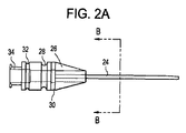
図2Aに示すように、カテーテルハブ26は、カテーテル24の手元端から延びる。細長くカスタムシェイプのハブ26は、当該ハブ26がカテーテルのドレッシングシステム10の他の構成要素と一体化することを可能にする様々な特徴のいずれかを備えることができる。特に、カテーテル24を挿入した後に、ハブ26をドレッシング組立体14に当てて、ハブ26をドレッシング組立体14に封止係合で取り付けることができる。ハブ26の長さを、最適なカテーテルの固定、封止及び操作を提供するためにちょうど必要な長さに最小化することができる。カスタマイズされたハブの長さ及び形状は、ハブ26の外側に沿って形成される、様々な封止・固定機構の作成/存在を有利に許容することができる。ハブ26の大きさ及び形状は、滅菌済みのドレッシング組立体14を適用する間に、ハブ26を適切に手動操作できるようにすることもでき、ドレッシング組立体14を適用したらすぐに、(例えば静脈注射ライン(IV lines)をカテーテル24等に取り付けるために)取り付けたドレッシング組立体14を通ってカテーテル24を操作できるようにすることもできる。カテーテル24の使用(例えばカテーテルへの静脈注射ラインの取り付け)を容易にするために、ハブ26がドレッシング組立体14を手元側に(proximally)過ぎて延びる、又はハブ26がドレッシング組立体14から手元側に突出するように、ハブ26の長さを選択することもできる。
As shown in FIG. 2A, the
ハブ26は、挿入されたカテーテルハブ26上の、滅菌済みのドレッシング組立体14を封止用に適用可能にする、一様の最大外径を有することができる。ハブ26を、剛性、半剛性又は柔軟性のある材料で作ることができる。例えば半剛性又は柔軟性のある材料で構成されるハブは、そうしないと滅菌済みのドレッシング組立体14を持ち上げたり緩めたりする働きをする、力ベクトルを有利に消散させることができる。(例えば血管内の配置を確認する、又はカテーテル24からの血液の適切なフラッシングを確認することを目的として)ハブ内に含まれる血液の視覚化を可能とするために、ハブ26を透明又は半透明とすることもできる。
The
ハブ26に、ドレッシング組立体14を滅菌封止し、ドレッシング組立体14をカテーテル24に対する適所に(逆もまた同様)固定する、スナップフィット型の封止機構を設けることもできる。ハブ26の外径が一様に保たれるように、この機構を構成することができる。この封止/嵌合位置を、滅菌済みドレッシング組立体14と結合するようにカスタム設計することができる。ある実施形態では、この嵌合位置を、ドレッシング組立体14のハブ受入チャネルに形成される対応する突出部がスナップフィットする、環状凹部28とする。
The
患者側の(distal)内側ストップフランジ30をカテーテルハブ26に設けて、ドレッシング組立体14のハブ受入チャネルに形成された対応する雌型の凹部と係合させることができる。フランジ30は、ドレッシング組立体14及び挿入部位に対してカテーテル24が不慮に引き抜かれることを防ぐのに役立つことができ、カテーテルハブ26をドレッシング組立体14に対して回転方向に固定するのに役立つこともできる。加えて、フランジ30は、ドレッシング組立体/カテーテルハブのインターフェースに生まれる滅菌封止を増強することができる。図2Bに示すようにフランジ30を八角形状とすることができ、図2Cに示すように2つの横方向のフランジ30’の形をとることができ、又はフランジを六角形状若しくは四角形状等の他の形状とすることができる。横方向のフランジ30’を、挿入されたカテーテル24に対して、より小さな輪郭の載置アングル(a lower profile resting angle)を可能にするように設計することができ、この構成はある場合には望ましい。フランジをそれだけで、ドレッシング材の対応する凹部の位置で、所定の位置へ留めることができ、又はカテーテルのドレッシング材のインターフェースでの環状の嵌合位置とともに留めることもできる。
A patient
凹部28に形成されるスナップフィット封止及びフランジ30に形成される封止は共に、カテーテル24を滅菌済みのドレッシング組立体14に最適に封止し固定する。さらに後述するように、ドレッシング組立体14を、カテーテル挿入部位の周りで患者の皮膚に同時に付着させ、ひいてはドレッシング組立体14及びカテーテル24を患者に固定することができる。従って、カテーテル24の、患者/血管に対する、長手方向及び回転方向の動きが妨げられ、これにより、患者の快適さを向上させ、外傷関連の血栓性静脈炎のリスクを最小化させることができる。
Both the snap-fit seal formed in the
カテーテルハブ26は、ハブ保護装置16に対する取付具及び/又は位置決め機構を備えることもできる。この取付具及び/又は位置決め機構は、カテーテルハブ26を滅菌済みドレッシング組立体14に取り付けるのに用いるスナップフィット嵌合部材と類似した、スナップフィット嵌合部材(例えば環状凹部32)の形をとることができる。初期配置中にドレッシング組立体14がカテーテルハブ26を覆って摺動する際に、ドレッシング組立体14がこの部位(環状凹部32等)に時期尚早に固定されることを妨げるために、この最初に直面する溝32を、ドレッシング組立体14のためのスナップフィット式の溝28よりも狭くすることができる。
The
ハブ26は、後述するように、ハブのキャップ22、並びに/又は、存在する様々な血管カテーテル及びコネクタのいずれかと嵌合するために、手元側インターフェース34を備えることもできる。
The
図3A及び3Bにハブのキャップ22を詳細に示す。ハブのキャップ22は、カテーテルハブ26の手元側インターフェース34と嵌合するために、ねじ切りされたインターフェース36を備えることができる。ハブのキャップ22は、カテーテルハブ26の中央腔(lumen)内に延び、当該中央腔と封止するように構成される雄型の突起38を備えることができる。ハブのキャップは、挿入針を針収容装置へ引き抜いた後の血液の逆流を防ぐ用途に役立ち、針収容装置が取り外された後、当該メンブランを剥がし/取り外して、例えばルアーロック(Luer Lock)装置又はインサイト(Insyte)装置の、配置を可能とする単純で着脱可能な滅菌済みのメンブランの形をとることもできる。図示するように、統合化されたキャップ22は、一様な直径を同様に有することができ、失血することなくカテーテル挿入針18の引き抜きを可能にでき、それによって、カテーテル24が挿入される際に、(ルアーロック(登録商標)型キャップ又はインサイト(登録商標)型キャップ等の)中間的なキャップ装置を迅速に取り付ける必要性を取り除くことができる。このことで、失血、滅菌状態の破壊等を有利に防止することができる。この一様の直径を持つ統合された封止キャップ22は、ドレッシング組立体14を配置した後、必要に応じて除去することができ、標準のルアーロック(登録商標)型キャップ装置又はインサイト(登録商標)型キャップ装置と交換することができる。あるいは又は加えて、この一様な直径を有する統合された封止キャップ22を、当該キャップ22が、既存の針を有する取り付けシステム及び無針取り付けシステムと嵌合できるように構成することができる。一様な直径を有する統合された封止キャップ22を、新規な無針取り付けシステムの一部として考案することもできる。
The
一様な直径を有するハブのキャップ22(「一様な」とは、例えばカテーテルハブの直径以下であり、カテーテルハブのフランジの直径よりも小さいことを意味する)をカテーテルハブ26を取り除いて図3A及び3Bに示し、嵌合されたハブのキャップ22及びスナップフィット式のカテーテルハブ26を全体的に一様の直径とすることを可能にする、取り付け機構並びに各構成要素の相対的な形状及び直径を示す。この一様の直径によって、スナップフィット式ドレッシング組立体14を、ハブのキャップ22とスナップフィット式のカテーテルハブ26との複合体上に取り付けて適所へ摺動させることができる。この(嵌合機構及びストップフランジを除く)ハブの一様の外径は、カテーテルハブと、カテーテルハブのチャネル部が位置するドレッシング材のチャネルとの間のデッドスペースを除去することを可能とする。この構成は、カテーテルハブとドレッシング材のハブのチャネルとの間に、血液又は他の物質が蓄積され、時間とともに滅菌状態に悪影響を及ぼす働きをするおそれを避けることができる。図3Bは、ハブのキャップ22の端面図を示し、キャップ22に含まれる再封止可能な機構40を示す図である。
A
図4A〜4Dに示すように、カテーテル組立体12は、ハブのキャップ22及び/又はカテーテルハブ26を予め取り付けておくことができる、着脱可能な収容装置20を備えることができる。図示された針収容装置20は、細長い伸縮する(telescoping)筒の形とすることができる。当該筒は複数の部分を備えることができ、当該部分は次第に増加する直径を有し、ガスケット又は他の封止部材を当該部分同士の間に有し、針収容装置20の内部に、単一の連続し封止された内部チャンバを形成することができる。当該部分のそれぞれにストップフランジを設けて、針収容装置が拡張している間に、当該部分が分離することを防止することができる。針収容装置は、プラスチック、ゴム、金属及び/又はこれらの組み合わせを含む、公知の様々な医療グレードの材料のいずれかで構成することができる。
As shown in FIGS. 4A-4D, the catheter assembly 12 can include a
カテーテル24を患者の血管内に首尾良く配置した後に、挿入針18はカテーテル24及びカテーテルハブ封止キャップ22から抜き取ることができる。(挿入されたカテーテル組立体12から引き抜かれるが、依然としてカテーテル組立体12に機械的に取り付けられている)引き抜かれた針18/針収容装置20が、滅菌済みのドレッシング組立体14を、挿入されたカテーテル組立体12に取り付けるのに用いるためのハンドルとして役立つように、針18を、安全な針収容装置20と一体化することができる。ドレッシング組立体14を配置した後、針18を収容する、展開された針収容装置20を、(脆い部分又は塑性切断(plastic breakaway)等の)様々な可能な機構の一つによって分離することができる。スナップフィット、螺合又は類似の可逆的分離機構を設けることもできる。従って、ドレッシング組立体14がカテーテル24上を適所へ摺動して、ドレッシング組立体14を適所でカテーテルハブ26に留めて、ドレッシング材を配備した後に、この「ハンドル」である針収容装置20を、カテーテルハブ26及び/又はハブ封止キャップ22から分離させることができる。例えばドレッシング材の配置後にカテーテルハブからハブキャップをネジを回して外すことによって、針収容装置及びハブキャップを共にひとつのユニットとして分離することもできる。新しいハブのキャップをそれから配置することができ、又は存在する「既製の」(インサイト、ルアーロック等の)中間コネクタ又は静脈注射ラインを取り付けることができる。ドレッシング組立体は、その時点でカテーテルに完全に取り付けられ固定され、このような分離・再取付の過程の間、ドレッシング組立体によってカテーテルを堅く拘束することを可能とする。
After the
使用に際し、カテーテル組立体12を予め組立てられた構成で滅菌済みのパッケージに設けることができる(例えば挿入針18、針収容装置20、ハブのキャップ22、カテーテルハブ26、及びカテーテル24を一緒に組立てる)。図4Aに示すように、挿入針18を用いて患者の皮膚表面を貫通して、カテーテル24の挿入を導くことができる。図4Bに示すように、針収容装置20の伸縮部42を延ばして、挿入針18を手元側に引き抜くことができる。この手順の間、針18をカテーテルのドレッシングシステム10内に完全に封入されたままにし、ひいては、システム10に必要な直径を保ちつつ、挿入針18の容易かつ安全な引き抜きを可能とする。図4Cに示すように針18がカテーテルハブ26から完全に引き抜かれた後も、拡張した/展開した針収容装置20は、ハブキャップ22及び/又はカテーテルハブ26に取り付けられたままである。後述するように、針収容装置20は、その後ドレッシング組立体14を取り付ける際に「ハンドル」として用いることができる。ドレッシング組立体14を適所でカテーテルハブ26に留めた後に、図4Dに示すように、針収容装置20が構成する「ハンドル」、及び針収容装置20に収容される針18を分離して、安全に廃棄することができる。針収容装置20の患者側端部は任意に、テーパを付けた部分又は円錐部分を備え、針収容装置20から、カテーテルハブ26又はハブのキャップ22へ、ドレッシング組立体を摺動させることを容易とすることができる。言い換えれば、針収容装置20の周りに患者側に配置されるドレッシング組立体の、カテーテルハブ及び/又はカテーテルハブのキャップへの摺動を容易にするように、針収容装置20を成形することができる。
In use, the catheter assembly 12 can be provided in a pre-assembled configuration in a sterilized package (e.g., the
図4E〜4Fは、滅菌済みドレッシング組立体を適用するための取り付けハンドルを設けるときに、挿入針18’の除去及び安全な収容を促進するための、代替的な実施形態の針収容装置20’を示す。図示するように、針収容装置20’は、挿入針18’の少なくとも一部を受けるような大きさの中央腔23’を画定する、細長シャフト21’を一般に備える。好ましくは、中央腔23’が挿入針18’全体を収容することができる。針収容装置20’は、針収容装置20’の周りに配置され、例えばスライダ25’から中央腔23’へ半径方向内側に延びる1つ以上の支柱を介するとともに、細長シャフト21’の外面に形成された1つ以上の長手方向のカットアウトチャネルを通って、針18’に連結されるスライダ25’を備えることもできる。使用に際しては、図4Eに示すように、スライダ25’、及びスライダ25’に連結される挿入針18’を、針18’がカテーテル24’の挿入を導くことができるような、患者側の前進位置に配置する。一旦カテーテル24’が患者に挿入された後、又は他の望まれるときはいつでも、スライダ24’を図4Fに示される位置へ、手元側に引き抜く又は収縮させることができる。スライダ24’を、シャフト21’に形成された長手方向のカットアウトチャネルに沿って手元側に引き寄せた際に、スライダ24’に連結された針18’は、カテーテル24’及びカテーテルハブ26’から、針収容装置へ引き抜かれる。特定のチェックポイントを越えて手動で回転させる等の、いくつかの機構のいずれかによって、スライダを適所でロックすることができる。
4E-4F illustrate an alternative embodiment needle containment device 20 'for facilitating removal and safe containment of the insertion needle 18' when providing an attachment handle for applying a sterile dressing assembly. Indicates. As shown, the needle containment device 20 'generally includes an elongate shaft 21' that defines a central cavity 23 'sized to receive at least a portion of the insertion needle 18'. Preferably, the central cavity 23 'can accommodate the entire insertion needle 18'. The needle
スライダ25’を、シャフト21’内に配置され、スライダ25’とシャフト21’の患者側端部との間に延びる、伸縮可能なシースに連結することができる。従って、スライダ25’を手元側に引き抜く際に、シースは、シャフト21’に形成される長手方向のカットアウトチャネルを覆って延びることができ、それによって、スライダ25’を引き抜く際に針18’を封入し、血液又は他の物質がカットアウトチャネルを通って漏れることを防止することができる。シースを、ラテックス、ニトリルゴム等の、公知の柔軟性のある様々な材料から構成することができる。 The slider 25 'can be coupled to a telescopic sheath disposed within the shaft 21' and extending between the slider 25 'and the patient end of the shaft 21'. Thus, when pulling the slider 25 'proximally, the sheath can extend over the longitudinal cutout channel formed in the shaft 21', thereby causing the needle 18 'when pulling the slider 25'. To prevent blood or other substances from leaking through the cutout channel. The sheath can be made of various known flexible materials such as latex and nitrile rubber.
図4A〜4Dに示す実施形態のように、図4E〜4Fに示す実施形態は、ドレッシング組立体を展開した針収容装置20’上に配置する際にハンドルの機能を果たすこともでき、カテーテル組立体から可逆的に分離されることができ、ドレッシング組立体を針収容装置20’からカテーテルハブ26’又はハブのキャップ22上で導くために、円錐状又はテーパを付けた患者側端部27’を有することができる。
Like the embodiment shown in FIGS. 4A-4D, the embodiment shown in FIGS. 4E-4F can also serve as a handle when the dressing assembly is placed on the deployed needle storage device 20 ', and the catheter assembly Can be reversibly separated from the body and has a conical or tapered patient end 27 'to guide the dressing assembly from the needle containment device 20' onto the catheter hub 26 'or the
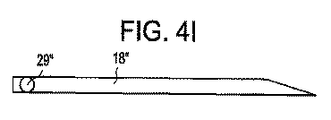
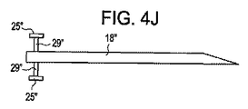
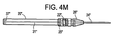
図4G〜4Nは、滅菌済みのドレッシング組立体を適用するために取り付けハンドルを設けるときに、挿入針18’’の除去及び安全な収容を促進するための、他の代替的な実施形態の針収容装置20’’を示す図である。図示するように、針収容装置20’’は一般に、挿入針18’’の少なくとも一部を受ける寸法の中央腔23’’を画定する、細長シャフト21’’を備える。好ましくは、中央腔23’’は挿入針18’’の全体を収容することができる。針収容装置20’’は、例えば、スライダ25’’から中央腔23’’へ、細長シャフト21’’の外面に形成される1つ以上のカットアウトチャネル31’’を通って半径方向内側に延びる(図4I〜4Jに示す)1つ以上のストラット29’’を経由して、針18’’に連結されるスライダ25’’も備える。図4Hに示すように、1つ以上のチャネル31’’は、主要長手方向部41’’を備えることができ、ストラット29’’をその中へ回転させて、針18’’の長手方向位置を細長シャフト21’’に対してロックすることができる、手元側及び/又は患者側の直角空間又は直角サイドカット33’’,35’’を備えることができる。図示される実施形態では、手元側のサイドカット33’’及び患者側のサイドカット35’’にそれぞれ形成される、手元側及び患者側の一方向の戻り止め37’’,39’’は、このロックアウト機構を補強する。
4G-4N illustrate another alternative embodiment needle for facilitating removal and safe containment of the insertion needle 18 '' when providing an attachment handle for applying a sterilized dressing assembly. It is a figure which shows accommodating apparatus 20 ''. As shown, the
使用に際し、図4G及び図4Mに示すように、針18’’がカテーテル24’’の挿入を導くことができるように、スライダ25’’、及びスライダ25’’に連結される挿入針18’’を、患者側の前進位置に配置する。この位置では、スライダ25’’に連結されたストラット29’’を、チャネル31’’の患者側サイドカット35’’内に配置するために、スライダ25’’を、細長本体21’’に対する第1回転方位に配置することができる。この位置では、患者側の戻り止め39’’は、スライダ25’’を適所にロックし、針収容装置20’’に対する針18’’の長手方向の不慮の動きを防止するのに効果的である。カテーテル24’’が患者に挿入された後、又はその他の所望する何時でも、(例えばストラット29’’が十分な力を加えて、患者側戻り止め39’’上を越えさせて、チャネル31’’の主長手方向部41’’へ移動させることによって)スライダ25’’を、細長本体21’’に対する第2回転方位へ回転することができる。スライダ25’’はそのように位置決めされ、図4Kに示すように、針収容装置20’’に対する針18’’の長手方向位置を自由に調整することができる。
In use, as shown in FIGS. 4G and 4M, a
従って、スライダ25’’を、図4L及び図4Nに示す位置へ向けて、手元側に引き抜く又は収縮させることができ、その際にスライダ25’’は、スライダ25’’に連結される針18’’を、カテーテル24’’及びカテーテルハブ26’’から針収容装置20’’へ引き抜く。(例えば針18’’が針収容装置20’’内に完全に収容される際に)一旦スライダ25’’のストラット29’’が手元側のサイドカット33’’に位置合わせされると、スライダ25’’を細長本体21’’に対して回転させて、針18’’を収縮位置でロックすることができる。例えば、スライダ25’’を回転させて、スライダ25’’に連結されるストラット29’’に患者側戻り止め37’’上を越えさせて、それによって、ストラット29’’を手元側のサイドカット33’’内でロックし、針18’’の針収容装置20’’に対する長手方向の不慮の動きを防止することができる。針収容装置20’’はそれ故に、ねじり解錠/施錠機構を有する摺動機構によって、針18’’を展開位置又は引出位置へロックする選択肢を提供する。ある実施形態では、この同じ回転運動を用いて、カテーテル及び滅菌済みのドレッシング材が配置された後、針格納装置を、カテーテルハブのキャップ又はカテーテルハブから分離することができる。
Accordingly, the slider 25 '' can be pulled out or contracted toward the position shown in FIGS. 4L and 4N, and the slider 25 '' is then moved to the
図4O〜4Tは、滅菌済みのドレッシング組立体を適用するための取り付けハンドルを設ける際に、挿入針18’’’の除去及び安全な収容を促進するための、針収容装置20’’’の他の代替的な実施形態を示す図である。図4Oに示すように、針18’’’の手元端部をピストン41’’’に固定的に嵌合させることができる。針18’’’を通って逆流する血液が、フィルタ43’’’を赤く染色して、針18’’’が血管内に挿入されたことを使用者に視覚的に示すように、フィルタ43’’’(綿又は他の滅菌済み繊維から構成される吸収部材等)を、ピストン41’’’に、針18’’’の手元側の出口で連結することができる。
FIGS. 4O-4T illustrate a
図示された針収容装置20’’’は一般に、ピストン41’’’と、フィルタ43’’’と、挿入針18’’’の少なくとも一部とを受ける寸法の中央腔23’’’を画定する細長本体21’’’を備える。好ましくは、中央腔23’’’は挿入針18’’’全体を収容することができる。針収容装置20’’’は、例えばスライダ25’’’から中央腔23’’’に向けて、細長シャフト21’’’の外面に形成される1つ以上のカットアウトチャネル(図示せず)を通って半径方向内側に延びる1つ以上のストラット(図示せず)を介する、針18’’’に連結されるスライダ25’’’を備えることもできる。スライダ25’’’を任意に、使用者による把持を容易とする寸法とすることができ、スライダ25’’’は、使用者の把持を容易にするために、粗面仕上げ(surface texturing)又は他の構成を備えることができる。スライダ25’’’は、細長シャフト21’’’の外表面沿いに摺動して、針18’’’の針収容装置20’’’に対する長手方向の動きをもたらすように構成される。
The illustrated
細長シャフト21’’’は任意に、スライダ25’’’の細長シャフト21’’’に対する動きを制限し抵抗するような表面構成を備えることができる。図示される実施形態において、細長シャフト21’’’には、手元側及び患者側の一方向ロック用突起45’’’,47’’’が設けられている。使用時において、スライダ25’’’を最初に、図4P及び図4Sに示すように、針18’’’が針収容装置20’’’の患者側端部から展開される、針収容装置20’’’に沿った第1位置に配置することができる。スライダ25’’’がそのように配置される際に、患者側のロック用突起47’’’は、針18’’’の展開位置からの動きを妨げる。この展開位置で、針18’’はカテーテル24’’’の挿入を導くことができる。一旦カテーテル24’’’が患者に挿入されると、又はその他の所望の時はいつでも、スライダ25’’’に患者側のロック用突起47’’’を歪めさせ、又は患者側ロック用突起47’’’上を越えさせるように、スライダ25’’’を十分な力で手元側に引き寄せることができる。それから、針18’’’の針収容装置20’’’に対する長手方向位置を、スライダ25’’’を、手元側及び患者側ロック用突起45’’’,47’’’の間で摺動させることで、自由に調整することができる。
The
スライダ25’’’を図4Q及び4Tに示す位置へ向かって、手元側に引き抜く又は収縮させることができ、その際スライダ25’’’は、スライダ25’’’に連結された針18’’’を、カテーテル24’’’及びカテーテルハブ26’’’から針収容装置20’’’内へ引き抜く。(例えば針18’’’が、針収容装置20’’’に完全に収容される時、)一旦スライダ25’’’が手元側のロック用突起45’’’に達すると、スライダ25’’’を手元側に十分な力で引き寄せて、スライダ25’’’に手元側突起45’’’を歪めさせ及び/又は越えさせて、針18’’’を収縮位置でロックすることができる。針収容装置20’’’はそれ故に、解錠/施錠機構を有する摺動機構によって、針18’’’を展開位置又は引抜位置内でロックする選択肢を提供する。図4Rに示すように、スライダ25’’’及び/又は針収容装置20’’’の少なくとも一部を透明にして、(例えばフィルタ43’’’の血液による染色を調べることで針18’’’が血管内に配置されたことを確認するために)フィルタ43’’’をユーザに対して可視化させることができる。図4Tに特に示すように、針収容装置20’’’の患者側端部は、ドレッシング組立体が針収容装置20’’’上を、ハブのキャップ22’’’又はカテーテルハブ26’’’の上へ摺動することを容易にするために、裾広がり部51’’’を備えることができる。
The slider 25 '' 'can be withdrawn or contracted towards the position shown in FIGS. 4Q and 4T, where the slider 25' '' is a needle 18 '' connected to the slider 25 '' '. 'Is withdrawn from the catheter 24' '' and the catheter hub 26 '' 'into the needle receiving device 20' ''. Once the slider 25 '' 'reaches the proximal locking projection 45' '' (for example, when the needle 18 '' 'is fully received in the needle storage device 20' ''), the slider 25 '' The needle 18 '' 'can be locked in the retracted position by pulling' to the proximal side with sufficient force, causing the slider 25 '' 'to distort and / or exceed the proximal projection 45' ''.
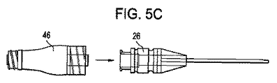
上述したように、また図5A〜5Dに示すように、カテーテルハブ26を、様々な標準のコネクタ又は構成要素のいずれかと嵌合するように構成することができる。図5A及び5Bは、標準のルアーロック(登録商標)型のコネクタ44のカテーテルハブ26への取り付けを示す図である。図5Aは分離された装置26,44を示し、図5Bは接続された装置26,44を示す。図5C及び5Dは、標準のインサイト(登録商標)型のコネクタ46のカテーテルハブ26への取り付けを示す図である。図5Cは分離された装置26,46を示し、図5Dは接続された装置26,46を示す。
As described above and as shown in FIGS. 5A-5D, the
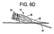
システム10のドレッシング組立体14の更なる詳細を図6A〜図6Gに示す。本明細書に記載される他の構造又は構成要素のいずれかのようなドレッシング組立体14を、システム10の残り(例えば「既製の」カテーテル及び他の装置)から独立して用いることができることは言うまでもない。図6Aはドレッシング組立体14の側面図を示し、図6Bはドレッシング組立体14の長手方向断面図であり、図6Cはドレッシング組立体14の平面図である。図示するように、ドレッシング組立体14は一般に、患者の皮膚に付着するように構成されるベースプレート48と、ベースプレート48から上方に延びて内部チャンバ52を画定する本体部分50とを備える。ドレッシング組立体14は、ドレッシング組立体14の手元側の表面からチャンバ52内へ延びるカテーテルハブ受入チャネル54を備えることもできる。ハブ受入チャネル54は、最小限のデッドスペースを残して、カテーテルハブ26を摺動させながら受け入れるように設計された一様な直径を有することができる。またハブ受入チャネル54は、スナップフィット式のカテーテルハブ26と嵌合するように設計された特定の輪郭機構を有することができる。例えば、環状の雄型突起56を、ハブ受入チャネル54内に設けることができ、環状の雄型突起56を、カテーテルハブ26に形成される環状凹部28とスナップフィットするように構成することができる。本明細書では、用語「スナップフィット」とは、カテーテルハブ26上のドレッシング組立体14の位置を、最終的な嵌合/封止位置へ「留める」ことを指す。「スナップフィット」は、最終的な嵌合/封止位置に達した際に生成される可聴式の及び/又は触覚式の反応も含み、この反応は、適切な位置決めが達成されたことを有利に使用者に示すことができる。カテーテルハブ26に形成される、ストップフランジ30又はストップフランジ30’を受けるために、カテーテル固定ストップフランジの嵌合位置58を設けることもできる。ドレッシング組立体14は、図6D〜6Eに示すように挿入されたカテーテル24上に設置された際に、ドレッシング組立体14は、チャンバ52内のカテーテル挿入部位の周囲を、固定的かつ滅菌状態で封止することができる。ハブ受入チャネル54を、標準のカテーテル、及び/又は、カテーテルのキャップ/接続装置と封止係合を形成するように構成することもできる。例えば、隔膜、Oリング、ガスケット、アイリスシール(iris seal)、ガスシール、フラップシール(flap seal)又は公知の他の封止機構をハブ受入チャネルに含めて、ハブ受入チャネルに挿入される構成要素と滅菌状態の封止を形成することができる。
Further details of the dressing
ドレッシング材をカテーテルシステム上に設置する間、滅菌状態を維持することができるように、ドレッシング組立体14の内面を、滅菌剤を含浸させた裏地で、処理し又は被覆することができる。
The inner surface of the dressing
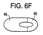
図6Fに示すように、ドレッシング組立体14の粘着プレート48は、カテーテル24上にドレッシング組立体14を設置することを容易にするために、任意に折り返し部60を備えることができる。粘着プレート48の様々な特徴を調整し、ドレッシング組立体14のその他、及びカテーテル皮膚挿入部位での患者の体表面に対する、粘着プレート48の最適な構造に到達することができる。例えば、粘着プレート48の寸法及び形状を、カテーテル挿入のために選ばれる身体部位に基づいて選択することができる。加えて、用いる接着剤の種類を含む、粘着プレート48の組成を最適化することができる。ドレッシング組立体14を、カテーテル部位の滅菌状態を長期間にわたり維持するように設計することができ、そのような長期間の固定を提供する最適な種類及びグレードの接着剤を用いることができる。特定のチャネルによってドレッシング複合体に適用される真空状態を用いて、ドレッシング材と取り付け位置での皮膚との間の滅菌状態の封止をさらに増強し維持することができる。
As shown in FIG. 6F, the
ドレッシング組立体14のいくつか又は全てを、(例えば柔軟又は半柔軟のシリコーン等の)柔軟な材料から構成して、ドレッシング組立体14又はドレッシング組立体14の一部を、体表の動きの間、カテーテル挿入部位での患者の皮膚に適合させることができる。ドレッシング組立体14は、ドレッシング組立体14が配置された後、滅菌封止を破壊することなしに、カテーテルハブ26を手動で把持及び操作することを可能にさせる、「把持が容易な(easy-grip)」カットアウト側面輪郭、又は同様の意図的な輪郭若しくは表面の手触りの変化を備えることもできる。この把持が容易な機構は、カテーテルハブ26を、封止及び固定の、仕様/要求を依然として満たしたまま、最も短い長さにさせることもできる。この把持が容易なグリップの表面を、カテーテルドレッシング複合体の把持及び制御に特に役立つ表面構成を念頭に置いて、特に設計することができる。図示するように、ドレッシング組立体14は、(1)患者に対するカテーテル24の最適な配置、(2)プレート48の最適な接着、及び(体表の動き/変化に対する)この接着の維持、(3)カテーテル24が配置される身体部分の、静的な及び/又は変化する輪郭の動きを許容する、最適な柔軟性、(4)ドレッシングカテーテルシステム10が接触し得る衣服、静脈注射ライン、又は他の装置との引っ掛かりを最小限とすること、を可能とする、人間工学的な、薄型の形状を有することもできる。カテーテル組立体上への設置を容易とすることを目的として、ドレッシング組立体を、折り畳み姿勢で梱包することができる。一旦ドレッシング組立体をカテーテルハブ上の適所に配置した後に、ドレッシング組立体を広げて、患者の皮膚表面上の適所に付着することができる。接着性の裏当てを、ドレッシング材を皮膚に接着する過程を最適化する、いくつかの可能な構成のひとつとすることができる。これらの構成は、例えば、必要に応じて逐次剥離される、複数の分離した裏打ち部品を備えることができる。裏打ちの拡張等の機能的な部材、又はひも等の付属の物体は、裏打ちの最適な剥離、及び粘着性表面を、カテーテルの皮膚への挿入部位での皮膚に最適に貼り付けるのに役立つことができる。
Some or all of the
例えば、カテーテルのフラッシュの適切さを保証する際に、ハブ26と、ハブ26のドレッシング組立体14への接続を観察する、及び/又は、ハブのコネクタを観察することを目的として、ドレッシング組立体14、又はドレッシング組立体14の任意の部分を任意に、透明又は半透明として、包含されるカテーテルハブの可視化を可能にすることができる。また、図6E〜図6Gに示すように、ドレッシング組立体14は、(滅菌チャンバ52への可逆的なアクセスを可能とする、再封止可能な窓装置等の)アクセス扉62を備えることもできる。可逆的に封止可能なアクセス扉/窓62は、カテーテル挿入部位の滅菌状態を維持するために、滅菌チャンバ52及びカテーテル挿入部位へのアクセスを許容することができる。この窓構造は、例えば、滅菌済みのチャンバ52及び/又はガスケット型のスナップフィット封止機構を有する柔軟なプラスチックシートを開き、これらへアクセスすることを許容するために、ドレッシング組立体14から剥離させることができる粘着性フィルムを備えることができる。アクセス扉/アクセス窓62は、滅菌剤を含浸させた材料の配置を許容することができ、又は一体的に取付けられた当該材料を有することができる。使用に際して、アクセス扉62をドレッシング組立体14から剥離させて、滅菌チャンバ52へのアクセスをもたらすことができる。その後、アクセス扉62をドレッシング組立体14に再封止することができ、又はアクセス扉62を廃棄して新しいアクセス窓のフラップ又はカバーに交換することができる。図示されるアクセス扉62は、チャンバ52の上側表面全体を実質的に区画するが、他の実施形態では、アクセス扉62は、この表面の一部のみを形成することができ、又はアクセス扉62はチャンバ52の他の表面を形成し、若しくはアクセス扉62をチャンバ52の他の表面に配置させることができる。
For example, in ensuring the proper flushing of the catheter, the dressing assembly is intended to observe the
ドレッシング組立体14は、第2の注入準備ができている封止可能な扉を備え、滅菌材料/溶液を、滅菌チャンバ内及び/又はカテーテルハブのチャネル内へ、注入/導入させることもできる。
The dressing
ドレッシング組立体14は、ハブ保護装置16用の取付機構及び/又は位置決め機構を備えることもでき、以下説明する当該機構は、カテーテルハブ26の滅菌状態を維持するのに役立つことができる。取付機構を、ハブ受入チャネル54の外側の(又は「機能する」)端部に形成することができ、取付機構は、患者側の内側ストップフランジ30をチャネル54の内側端部で受けるために用いられる凹部に類似する、八角形状、六角形状、卵形、又は他の形状の凹部64の形をとることができる。この雌型の嵌合位置64を、ハブ保護装置16を受けて固定するために設計することができる。
The dressing
使用に際し、図7Aに示すように、ドレッシング組立体14を、完全に延在され展開された(しかし依然として取り付けられている)針収容装置20上で摺動させることができ、前記装置20は取付「ハンドル」として用いられる。図7Bに示すように、ドレッシング組立体14をスナップフィット式のカテーテルハブ26上の特定の嵌合位置での最終的な位置へ、患者側に前進させることができる。ドレッシング組立体14をそれから、カテーテルハブ26に設置して、患者に付着させることができる。一旦ドレッシング組立体14が設置されると、図7Cに示すように、針収容装置20をカテーテルハブ26又はハブのキャップ22から分離させることができる。
In use, as shown in FIG. 7A, the dressing
ドレッシング組立体14の他の典型的な使用では、標準の「既製の」カテーテル及び/又は(例えばルアーロックの又はインサイトの)カテーテルハブのキャップ装置を、(例えば、挿入されたカテーテルハブ/ハブのキャップを、ハブ受入チャネル54を通って挿入し、その後ドレッシング材を、カテーテルハブ上で皮膚挿入部位へ患者側に摺動させて、ドレッシング組立体14とカテーテルハブとの間で封止係合を形成することによって)ドレッシング材に連結することができる。粘着裏地(adhesive backing)の除去は、ドレッシング組立体の皮膚への付着を構成し、ひいてはカテーテルの皮膚への挿入部位周囲の封止を構成することができる。必要に応じて、アクセス扉62をはぎ取って、チャンバ52を露出させて、チャンバの滅菌又は他の洗浄を可能にすることができ、その後アクセス扉62をドレッシング組立体14に再封止し、又は新しいカバーフラップと交換することができる。
Other typical uses of the dressing
上述したように、ドレッシング組立体14を用いて、動脈モニタリングライン、血管造影法及びステント・グラフト留置術等の血管内処置のためのアクセス・シース、大動脈内バルーンポンプ及び人工心臓等の血管内治療装置用のアクセス・シースを含む、他の様々な装置をドレッシングし、滅菌することもできる。これらの他の装置を、公知の標準の種類の装置とすることができ、又はカテーテル24及びカテーテルハブ26に関して上述したようにカスタマイズして、ドレッシング装置の封止の滅菌性、安全性及び安定性を強化することができる。例えば、このような装置を、1つ以上のカスタマイズしたストップフランジ、凹部、スナップシール位置等を備えるように変更することができる。当然のことながら、当該装置が患者に挿入される前又は後に、ドレッシング組立体14は当該装置上を摺動することができ、当該装置が挿入された後に、当該装置を操作するためにドレッシング組立体14を使用することもできる。
As described above, the dressing
ドレッシング組立体14は、挿入部位での止血を有利に提供し、カテーテル法、並びに皮膚表面が穿刺され、及び/又は患者の血管系にアクセスする他の類似する処置に関連して通常起きる失血を防止し及び/又は封じ込めることもできる。外傷が治癒する間、挿入部位の滅菌状態を保護し維持するために、処置が完了し、カテーテル又は他の装置が除去された後に、ドレッシング材14を適所に残すこともできる。例えば、ある実施形態では、処置の完了後、ドレッシング材を6〜8時間適所に残すことができる。
The dressing
ドレッシング組立体14は、ポートであって、真空源又は圧力源が当該ポートを通ってドレッシング組立体14の内面に連結されることができるポートを備えることもできる。例えば、教示の柔軟なドレッシング材を、皮膚表面及び埋め込まれたカテーテルへ引き付けるために、ドレッシング材14を柔軟とした実施形態に、真空状態を適用することができ、それによって、ドレッシング材とカテーテルとが構成する滅菌状態をさらに増強することができる。加えて、圧力源をドレッシング材に適用して、ドレッシング材内に配置された、及び/又は、ドレッシング材と連結したバルーンを、膨張させることができる。バルーンが膨張する際に、バルーンは拡張して、ドレッシング組立体14の内面を実質的に満たし、ドレッシング組立体14内に配置されるカテーテルに圧力をかけて、それによって、カテーテルと皮膚との結合をさらに安定させる。カテーテルが除去された後に、バルーンを膨張させて挿入部位を圧迫することもでき、それによって、失血を防止し、傷の治癒を促進することができる。
The dressing
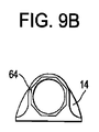
上述したように、システム10は、ハブ保護装置16を備えることもできる。図8に示すように、ハブ保護装置16は一般に、ハブ保護装置16に形成され、ドレッシング組立体14及び/又はハブのキャップ22から突出するカテーテルハブ26の部分を受ける寸法の、ボア66を有するキャップの形をとる。ハブ保護装置16は、カテーテルハブ26内に形成される、対応する雌型の凹部32(図2参照)に、係合及び/又はスナップフィットするように構成される、雄型環状突起70を備える。保護装置16は、(図6A〜6C及び9Bにも示される)ドレッシング組立体14内に形成される、対応する嵌合機構64と係合するように構成される、(図9Aにも示される)嵌合機構68も備える。
As described above, the
使用に際し、図9Aに示すハブ保護装置16、及び図9Bに示すドレッシング組立体14は、これらの図に示すように、互いに向き合い/互いに対面し合い、それから、スナップフィット式のカテーテルハブ26上で押し合って、最終的な嵌合構成を達成する。言い換えると、図10A〜図10Cに示すように、ハブ保護装置16が、設置されたカテーテルハブ26及び/又は設置されたドレッシング材14と係合する(例えば留める)まで、ハブ保護装置16を、カテーテルハブ26の突出する手元端部上に設置することができる。スナップフィット式カテーテルハブ26とスナップフィット式ドレッシング組立体14との間の嵌合と同様に、スナップフィット式ハブ保護装置16を、2つの、分離しているが相補的な嵌合位置によって固定することができる。この2つの嵌合位置とは、(1)ハブ保護装置16とカテーテルハブ26との間のスナップフィット位置、(2)ハブ保護装置16とスナップフィット式ドレッシング本体14との間の八角形(又は他の形状の)の雄雌のインターフェース、である。
In use, the
ハブ保護装置16は、「補助的なカテーテルハブの滅菌及び封止の保護装置」とも呼ばれ、覆われた血管内カテーテルハブ26の機能端部(取付けられた滅菌済みドレッシング組立体14から突出し、静脈注射ライン及び他の装置が取付けられるハブ26の端部)を人間工学的に覆い、滅菌に保護することができる。ハブ保護装置16の利用は、完全に任意のものであり、システム10をハブ保護装置16無しに容易に用いることができる。
The
上述したように、カテーテルハブ26の、周方向のスナップフィット溝32を、(例えば、後続の「下流の」ドレッシング材のスナップフィット溝28よりも狭くすることで)ドレッシング組立体14がカテーテルハブ26上を最終的な設置位置へ摺動する際に、ドレッシング組立体14が最初の溝32へ「時期尚早に」取付けられることを抑制するように設計することができる。
As described above, the dressing
保護キャップ16の取付けが、すぐに使える洗浄/滅菌状態で、ハブ26を保存するのに役立つように、ハブ保護装置16は、抗菌の/又は抗生の、洗浄/滅菌溶液を含浸した裏地材料を備えることもできる。従って、装置16が除去されると、使用前にハブ26をアルコールで拭き取る必要はない。ハブ保護装置16の対向する全表面を、このような方法で処理することができ、又はカテーテルハブのチャネル66等の特定の部分のみを、このような方法で処理することができる。同様に、ドレッシング材の任意の部分(例えばハブ受入チャネル又は滅菌チャンバ)を、抗菌の及び/又は抗生の、洗浄/滅菌材料で裏打ちすることができる。
The
ある実施形態では、ハブ保護装置16は、滑らかで単純な弧、又は、ドレッシング組立体14に取付けられた際に「引っかからない」他の輪郭を提供する形状を有することができ、これにより、カテーテルハブ26を粘着性ベースプレート48に対して有利に固定させることができ、カテーテルハブ26を支持することができ、カテーテルのドレッシングシステム10上の衣服又は他の部材の引っ掛かりを防ぎ又は最小化することができる。ハブ保護装置16が、患者の快適性及び長期間の容易な使用を全面的に改善することができることは言うまでもない。
In certain embodiments, the
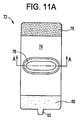
図11A〜図11Dは、本明細書で開示したカテーテルシステムとともに用いられる保護カバーの、例示的な一実施形態を示す。患者が、保護カバー無しでは、カテーテルのドレッシングシステムの完全性を脅しうる活動に携わる際に、及び/又は、小児科患者又は精神状態が変化した患者にとって、保護カバーは特に有益とすることができる。保護カバーを、ドレッシング組立体上に適用することができ、患者の身体の該当部分に適した様々な手段で患者の身体に固定することもできる。ドレッシング材を患者の腕に適用する際に、例えば、ベルクロ(登録商標)型の閉鎖を有する弾性アームバンドを用いることができる。保護カバーはシステムを保護することができ、ドレッシング組立体の粘着性封止の完全性を増強することもできる。ある実施形態では、保護カバーを、ドレッシング組立体の形状に適合するよう成形された、剛性又は半剛性のプラスチックから構成することができる。 11A-11D illustrate an exemplary embodiment of a protective cover for use with the catheter system disclosed herein. Without a protective cover, the protective cover can be particularly beneficial when engaged in activities that can threaten the integrity of the catheter dressing system and / or for pediatric patients or patients whose mental condition has changed. A protective cover can be applied over the dressing assembly and can be secured to the patient's body by a variety of means suitable for the relevant portion of the patient's body. When applying the dressing to the patient's arm, for example, an elastic armband having a Velcro-type closure can be used. The protective cover can protect the system and can also enhance the integrity of the adhesive seal of the dressing assembly. In certain embodiments, the protective cover can be constructed from a rigid or semi-rigid plastic shaped to conform to the shape of the dressing assembly.
図示される実施形態では、保護カバー72は一般に、患者の付属器官を包み込み、閉じて、封止されて、及び/又はそれ自身に固定されることができる、平坦なシート74の形をとる。図11C〜11Dに示すように、シート74は、挿入されたカテーテルのドレッシングシステム10の外側の輪郭に実質的に合致するように成形される隆起部76を備えることができる。シート74はフック部78及びループ部80も備え、フック部78及びループ部80は一緒に、シート74で(腕、脚等の)身体部分を包み込み、シート74をそれ自体に留める、フック及びループ固定システムを形成する。フック部及びループ部78,80の分離を容易にするために、プルタブ82を設けることもできる。保護カバーを、伸縮性及び/又は粘着性の材料で構成することができ、カテーテルを挿入する患者の部分、及び患者の相対的寸法によって、保護カバーを様々な寸法で設けることができる。保護カバー72の皮膚対向面を、滅菌剤で被覆することができる。フック及びループ固定システムを図示したが、(接着剤、ステープル、縫合、磁石、摩擦嵌め等の)公知の種々の取付機構のいずれかを採用することもできる。加えて、図示される実施形態の保護カバー72は、患者の身体部分を包むことができるが、保護カバーを、身体部分を包むことなく患者に取付けるように設計することもできる。
In the illustrated embodiment, the
本明細書に記載されるシステムを、ドレッシング材、カテーテル、ハブ、ハブのキャップ、ハブ保護装置、挿入針、針収容装置、及び/又は、様々な寸法のカテーテル、患者、身体部分等で使用するための、様々な寸法及び形状の、他の構成要素を備えるキットの形をとるパッケージ化することもできる。キットは、止血帯、調製溶液(preparation solutions)、溶液塗布器、滅菌生理食塩水洗浄、及び/又は滅菌済み手袋等の、滅菌部位の準備及び滅菌済みカテーテルの挿入のための様々な部材を備えることもできる。本明細書に記載される装置を、一度使用したら廃棄するように設計することができ、また複数回使用するように設計することもできる。しかしながら、いずれにしても、装置を少なくとも一度使用した後、装置を再利用できるように修理することができる。ここでいう修理には、装置の分解、その後に続く特定の要素の洗浄又は交換、及びその後の再組立の手順の任意の組み合わせを含むことができる。特に、装置を分解して、装置の特定の要素又は部品のいずれかを任意の組み合わせで、選択的に交換したり、取り除いたりすることができる。特定の部品の洗浄後及び/又は交換後には、修理施設で、またはカテーテル法の処置の直前に医療提供者によって、装置を次に使用するために再組立することができる。当業者にとって、装置の修理に、分解、洗浄/交換及び再組立のための、様々な技術を利用することができることは明らかである。かかる技術の利用、及びかかる技術を利用して修理された装置はすべて、本発明の範囲内に含まれる。 The systems described herein are used with dressings, catheters, hubs, hub caps, hub protectors, insertion needles, needle containment devices, and / or various sized catheters, patients, body parts, etc. It can also be packaged in the form of a kit with other components of various dimensions and shapes. The kit includes various components for preparing a sterile site and inserting a sterile catheter, such as tourniquets, preparation solutions, solution applicators, sterile saline wash, and / or sterile gloves. You can also. The devices described herein can be designed to be discarded once used, or can be designed to be used multiple times. In any case, however, the device can be repaired so that it can be reused after it has been used at least once. Repairs herein may include any combination of equipment disassembly, subsequent cleaning or replacement of certain elements, and subsequent reassembly procedures. In particular, the device can be disassembled and any particular element or part of the device can be selectively replaced or removed in any combination. After cleaning and / or replacement of certain parts, the device can be reassembled for subsequent use at a repair facility or by a health care provider immediately prior to a catheterization procedure. It will be apparent to those skilled in the art that various techniques for disassembly, cleaning / replacement, and reassembly can be used to repair the device. Use of such techniques and devices repaired using such techniques are all within the scope of the present invention.
好ましくは、本明細書に記載される発明は、使用前処理がなされる。まず、新規の装置又は使用された装置を得て、必要に応じて洗浄する。機器をその後滅菌することができる。ある滅菌技術では、器具は、閉じられ封止されたコンテナ(例えばプラスチック又はタイベック(TYVEK)のバッグ)内に配置される。コンテナ及び装置をその後、当該コンテナを貫通する(ガンマ線、X線又は高エネルギー電子等の)放射線場に配置する。放射線はコンテナ内の装置上の細菌を殺菌する。滅菌された装置をそれから、滅菌済みの容器内に保管することができる。医療現場でこの封止されたコンテナが開かれるまで、当該コンテナによって装置は滅菌状態に保たれる。 Preferably, the invention described herein is pre-use treated. First, a new device or a used device is obtained and cleaned as necessary. The instrument can then be sterilized. In one sterilization technique, the instrument is placed in a closed and sealed container (eg, a plastic or TYVEK bag). The container and device are then placed in a radiation field (such as gamma rays, x-rays or high energy electrons) that penetrates the container. The radiation sterilizes bacteria on the device in the container. The sterilized device can then be stored in a sterilized container. Until the sealed container is opened at the medical site, the container keeps the device sterile.
装置を滅菌することが好ましい。装置の滅菌は、ベータ放射線、ガンマ放射線、エチレンオキシド、蒸気及び/又は(寒冷浸透等の)液浴を含む、公知のあらゆる方法によって行うことができる。 It is preferred to sterilize the device. Sterilization of the device can be done by any known method including beta radiation, gamma radiation, ethylene oxide, steam and / or a liquid bath (such as cold infiltration).
当業者は、上述した実施形態に基づく、本発明のさらなる構成及び効果を認識することができるであろう。したがって、本発明は添付の特許請求の範囲に表された事項を除き、具体的に図示され、明細書に記載された事項に限定されるものではない。本明細書で引用したすべての刊行物及び文献は、その全内容が参照されて本明細書に明示的に援用されるものとする。 One skilled in the art will appreciate further configurations and advantages of the invention based on the above-described embodiments. Accordingly, the invention is not limited to what is specifically shown and described in the specification, except as indicated in the appended claims. All publications and references cited herein are hereby expressly incorporated by reference in their entirety.
Claims (24)
前記カテーテル組立体から手元側に延びる針収容装置であって、前記針収容装置は、前記埋め込み型カテーテルの内部腔を通って配置される挿入針に連結する、針収容装置と、
前記カテーテルハブ上を摺動して、前記カテーテルハブ及びカテーテル挿入部位を囲んで周囲の封止を形成するように構成されるドレッシング組立体と、
を備えるカテーテルシステムであり、
前記針収容装置が、前記針収容装置に連結される前記挿入針が前記埋め込み型カテーテルを通って完全に挿入された第1位置と、前記挿入針が前記埋め込み型カテーテルから完全に引き抜かれた第2位置とでロック可能であり、
前記針収容装置は細長シャフトとスライダと戻り止めとを備え、前記スライダを、前記スライダに連結される前記挿入針が前記埋め込み型カテーテルを通って完全に挿入された第1位置と、前記挿入針が前記埋め込み型カテーテルから完全に引き抜かれた第2位置とに配置できるように、前記スライダは前記細長シャフトに対して摺動可能であり、前記スライダは前記挿入針に連結され、前記戻り止めは、前記スライダを適所にロックし、前記針収容装置に対する前記挿入針の不慮の動きを防止するロックアウト機構を補強する、カテーテルシステム。 A catheter assembly comprising an implantable catheter and a catheter hub formed at a proximal end of the implantable catheter;
A needle storage device extending from the catheter assembly to the proximal side, wherein the needle storage device is coupled to an insertion needle disposed through an internal cavity of the implantable catheter; and
A dressing assembly configured to slide over the catheter hub to form a peripheral seal around the catheter hub and catheter insertion site;
A catheter system comprising:
A first position in which the insertion needle coupled to the needle accommodation device is completely inserted through the implantable catheter; and a first position in which the insertion needle is completely withdrawn from the implantable catheter. It is lockable in the 2 position,
The needle receiving device includes an elongated shaft, a slider, and a detent, and the slider has a first position where the insertion needle connected to the slider is completely inserted through the implantable catheter, and the insertion needle. Is slidable relative to the elongated shaft so that the slider is connected to the insertion needle, and the detent is A catheter system that reinforces a lockout mechanism that locks the slider in place and prevents inadvertent movement of the insertion needle relative to the needle storage device.
請求項1に記載のカテーテルシステム。 A balloon disposed within the dressing assembly, wherein when the dressing assembly mates with a skin surface, the balloon is operably coupled with an inflation cavity accessible from the outside of the dressing assembly. , Further comprising a balloon,
The catheter system according to claim 1.
患者の皮膚に付着するように構成される粘着性プレートであって、前記粘着性プレートは開口部を含み、前記開口部を通じて前記カテーテル組立体の少なくとも一部を受けることができる、粘着性プレートと、
前記粘着性プレートに固定的に付着される本体部分であって、前記本体部分は、前記カテーテル組立体と周囲を封止するように構成される手元側の開口部を含む、本体部分と、
前記本体部分と連結され、選択的に前記本体部分から剥離され及び前記本体部分に付着するように構成される、再封止可能及び交換可能なフラップ部と、
を備え、
前記ドレッシング組立体が患者の皮膚表面へ付着する際に、前記本体部分及び前記フラップ部はともに、前記患者の皮膚表面と滅菌封止されたチャンバを画定する、請求項1に記載のカテーテルシステム。 The dressing assembly is
An adhesive plate configured to adhere to a patient's skin, wherein the adhesive plate includes an opening through which at least a portion of the catheter assembly can be received; ,
A body portion fixedly attached to the adhesive plate, the body portion including a proximal opening configured to seal the catheter assembly and the periphery; and
A resealable and replaceable flap portion coupled to the body portion and configured to selectively peel from and adhere to the body portion;
With
The catheter system of claim 1, wherein the body portion and the flap portion together define a sterile sealed chamber with the patient's skin surface as the dressing assembly attaches to the patient's skin surface.
Applications Claiming Priority (7)
| Application Number | Priority Date | Filing Date | Title |
|---|---|---|---|
| US201161437862P | 2011-01-31 | 2011-01-31 | |
| US61/437,862 | 2011-01-31 | ||
| US201161482124P | 2011-05-03 | 2011-05-03 | |
| US61/482,124 | 2011-05-03 | ||
| US201161482564P | 2011-05-04 | 2011-05-04 | |
| US61/482,564 | 2011-05-04 | ||
| PCT/US2012/021196 WO2012106088A2 (en) | 2011-01-31 | 2012-01-13 | Snap-seal sterile intravascular catheter-dressing system |
Publications (3)
| Publication Number | Publication Date |
|---|---|
| JP2014509226A JP2014509226A (en) | 2014-04-17 |
| JP2014509226A5 JP2014509226A5 (en) | 2015-03-05 |
| JP5837094B2 true JP5837094B2 (en) | 2015-12-24 |
Family
ID=46577932
Family Applications (1)
| Application Number | Title | Priority Date | Filing Date |
|---|---|---|---|
| JP2013551993A Active JP5837094B2 (en) | 2011-01-31 | 2012-01-13 | Snap-sealed sterile intravascular catheter dressing system |
Country Status (5)
| Country | Link |
|---|---|
| US (1) | US8715242B2 (en) |
| EP (1) | EP2670469A4 (en) |
| JP (1) | JP5837094B2 (en) |
| CN (1) | CN103635225B (en) |
| WO (1) | WO2012106088A2 (en) |
Families Citing this family (50)
| Publication number | Priority date | Publication date | Assignee | Title |
|---|---|---|---|---|
| WO2007006055A2 (en) | 2005-07-06 | 2007-01-11 | Vascular Pathways Inc. | Intravenous catheter insertion device and method of use |
| EP2150304B1 (en) | 2007-05-07 | 2010-12-01 | Vascular Pathways Inc. | Intravenous catheter insertion and blood sample devices and method of use |
| US10682507B2 (en) | 2009-10-29 | 2020-06-16 | One Iv Solutions, Llc | Catheter extension with integrated circumferentially sealing securement dressing |
| BR112012010227A2 (en) * | 2009-10-29 | 2018-03-20 | E Helm Robert | sterile sealed catheter dressings |
| US9180275B2 (en) | 2011-01-31 | 2015-11-10 | Robert E. Helm | Catheter-dressing systems with integrated flushing mechanisms |
| US10384039B2 (en) | 2010-05-14 | 2019-08-20 | C. R. Bard, Inc. | Catheter insertion device including top-mounted advancement components |
| US8932258B2 (en) | 2010-05-14 | 2015-01-13 | C. R. Bard, Inc. | Catheter placement device and method |
| US11925779B2 (en) | 2010-05-14 | 2024-03-12 | C. R. Bard, Inc. | Catheter insertion device including top-mounted advancement components |
| US9950139B2 (en) | 2010-05-14 | 2018-04-24 | C. R. Bard, Inc. | Catheter placement device including guidewire and catheter control elements |
| US9872971B2 (en) | 2010-05-14 | 2018-01-23 | C. R. Bard, Inc. | Guidewire extension system for a catheter placement device |
| US8690833B2 (en) | 2011-01-31 | 2014-04-08 | Vascular Pathways, Inc. | Intravenous catheter and insertion device with reduced blood spatter |
| EP3563898B1 (en) | 2011-02-25 | 2020-11-11 | C.R. Bard, Inc. | Medical component insertion device including a retractable needle |
| USD903101S1 (en) | 2011-05-13 | 2020-11-24 | C. R. Bard, Inc. | Catheter |
| US9155866B2 (en) * | 2012-09-13 | 2015-10-13 | Becton, Dickinson And Company | Luer securement device |
| US9272088B2 (en) | 2012-09-13 | 2016-03-01 | Becton, Dickinson And Company | Intravenous catheter inserter |
| US9320840B2 (en) | 2012-10-05 | 2016-04-26 | Luis F. Angel | Catheter vacuum dressing apparatus and methods of use |
| US9629983B2 (en) * | 2013-03-08 | 2017-04-25 | Ethicon, Inc. | All in one antimicrobial dressing for catheter coverage |
| CA2902058A1 (en) * | 2013-03-15 | 2014-09-18 | Stryker Corporation | Assembly for positioning a sterile surgical drape relative to optical position sensors |
| US10792490B2 (en) | 2013-11-12 | 2020-10-06 | Medtronic, Inc. | Open channel implant tools and implant techniques utilizing such tools |
| EP3169394A4 (en) * | 2014-05-23 | 2018-04-25 | Viaderm, LLC | Vacuum assisted percutaneous appliance |
| CN106604681B (en) * | 2014-07-02 | 2018-06-01 | 赛特萨弗股份有限公司以利尼厄斯医药的名义经营 | Vein access device |
| WO2016037127A1 (en) | 2014-09-05 | 2016-03-10 | C.R. Bard, Inc. | Catheter insertion device including retractable needle |
| US11083491B2 (en) | 2014-12-09 | 2021-08-10 | Medtronic, Inc. | Extravascular implant tools utilizing a bore-in mechanism and implant techniques using such tools |
| US10265506B2 (en) * | 2015-02-02 | 2019-04-23 | Quick Snap Medical Supply, LLC | Vascular access devices and methods |
| USD903100S1 (en) | 2015-05-01 | 2020-11-24 | C. R. Bard, Inc. | Catheter placement device |
| US10471235B2 (en) * | 2015-05-01 | 2019-11-12 | The Board Of Trustees Of The Leland Stanford Junior University | Systems and methods for protecting umbilical stumps |
| KR102553637B1 (en) | 2015-05-15 | 2023-07-07 | 씨. 알. 바드, 인크. | Catheter Placement Device Including Extendable Needle Safety Component |
| DK3552652T3 (en) | 2015-08-18 | 2021-07-12 | Braun Melsungen Ag | CATHETER FACILITIES WITH VALVES |
| JP6885929B2 (en) | 2015-09-09 | 2021-06-16 | ベー.ブラウン メルスンゲン アクチェンゲゼルシャフト | Infusion systems, connectors for use with catheter devices, and related methods |
| US10569054B2 (en) | 2015-11-24 | 2020-02-25 | Augustine Biomedical And Design Llc | Catheter anchoring device |
| US20170165437A1 (en) | 2015-12-15 | 2017-06-15 | Bert Kamolsit Lopansri | Tamper-resistant enclosures for fluid lines |
| EP4309725A3 (en) * | 2016-02-18 | 2024-04-17 | Smiths Medical ASD, Inc. | Closed system catheter |
| CN107233641A (en) * | 2016-03-29 | 2017-10-10 | 美敦力公司 | A kind of epidermis indwelling apparatus for guided puncture |
| US10772611B2 (en) | 2016-05-20 | 2020-09-15 | Smiths Medical Asd, Inc. | Needle assembly with flexible catheter nose for diagnostic sampling of fluid |
| CN116173370A (en) | 2016-09-12 | 2023-05-30 | C·R·巴德股份有限公司 | Blood flash indicator for catheterization apparatus |
| WO2018125845A1 (en) | 2016-12-27 | 2018-07-05 | Vasonics, Llc | Catheter housing |
| BR112019018016B1 (en) | 2017-03-01 | 2023-10-24 | C.R. Bard, Inc. | CATHETER INSERTION TOOL |
| EP3600516A4 (en) * | 2017-03-21 | 2021-01-20 | Velano Vascular, Inc. | Devices and methods for fluid transfer through a placed peripheral intravenous catheter |
| WO2019173641A1 (en) | 2018-03-07 | 2019-09-12 | Bard Access Systems, Inc. | Guidewire advancement and blood flashback systems for a medical device insertion system |
| EP3788966A4 (en) * | 2018-05-16 | 2021-08-25 | Terumo Kabushiki Kaisha | Compression device and compression method |
| AU2019294228A1 (en) | 2018-06-25 | 2021-01-28 | Vasonics, Inc | Catheter securement, stabilization, and anti-microbial device |
| USD921884S1 (en) | 2018-07-27 | 2021-06-08 | Bard Access Systems, Inc. | Catheter insertion device |
| WO2020127328A1 (en) | 2018-12-17 | 2020-06-25 | B. Braun Melsungen Ag | Over-the-needle catheter assemblies and related manufacturing method |
| US11497891B2 (en) * | 2018-12-31 | 2022-11-15 | Becton, Dickinson And Company | Vascular access connector support device, systems, and methods |
| CN110302407B (en) * | 2019-06-26 | 2023-11-28 | 温州维科生物实验设备有限公司 | Portable space degerming device |
| US10820933B1 (en) | 2019-07-15 | 2020-11-03 | Osteon Medical LLC | Kyphoplasty system and method |
| JP2022545447A (en) | 2019-08-19 | 2022-10-27 | ベクトン・ディキンソン・アンド・カンパニー | Midline catheter placement device |
| US11957873B2 (en) | 2020-02-04 | 2024-04-16 | Augustine Biomedical And Design, Llc | IV extravasation detection device |
| WO2023188853A1 (en) * | 2022-03-30 | 2023-10-05 | テルモ株式会社 | Drug solution administration device |
| US11903628B1 (en) | 2023-04-20 | 2024-02-20 | Osteon Medical LLC | Kyphoplasty system and method |
Family Cites Families (100)
| Publication number | Priority date | Publication date | Assignee | Title |
|---|---|---|---|---|
| US3683911A (en) | 1970-08-13 | 1972-08-15 | Pelam Inc | Protective seal for catheter |
| US3918446A (en) | 1974-05-03 | 1975-11-11 | E Med Corp | Securement device for intravenous catheter and its tubing |
| US4515592A (en) | 1980-05-13 | 1985-05-07 | Arrow International, Inc. | Catheter shield |
| US4327723A (en) | 1980-05-13 | 1982-05-04 | Arrow International, Inc. | Catheter shield |
| US4392853A (en) | 1981-03-16 | 1983-07-12 | Rudolph Muto | Sterile assembly for protecting and fastening an indwelling device |
| DE3129931C2 (en) * | 1981-07-29 | 1983-10-13 | Institut für wissenschaftliche Photographie und Kinematographie Willi Fischer, 1000 Berlin | Medical bandage to fix a probe |
| DE3140192C2 (en) | 1981-10-09 | 1985-05-02 | Dr. Eduard Fresenius, Chemisch-pharmazeutische Industrie KG, 6380 Bad Homburg | catheter |
| US4464178A (en) | 1981-11-25 | 1984-08-07 | Dalton Michael J | Method and apparatus for administration of fluids |
| US4551137A (en) | 1982-10-07 | 1985-11-05 | Cook Incorporated | Flexible sheath assembly for an indwelling catheter |
| US4634433A (en) | 1982-10-07 | 1987-01-06 | Cook, Incorporated | Flexible sheath assembly for an indwelling catheter |
| US4551136A (en) | 1983-04-11 | 1985-11-05 | Medex, Inc. | Pressure infusor |
| US4563177A (en) | 1983-12-22 | 1986-01-07 | Kamen Dean L | Catheter stabilization pad |
| US4781695A (en) | 1986-07-11 | 1988-11-01 | Dalton Michael J | Implantable fluid dispenser |
| US4767411A (en) | 1987-07-14 | 1988-08-30 | Edmunds L Henry | Protective catheter sleeve |
| US4966590A (en) | 1988-12-13 | 1990-10-30 | Kalt Medical Corporation | IV Clamp with membrane dressing |
| US5074847A (en) * | 1989-05-01 | 1991-12-24 | Century Plastics, Inc. | Needle shield with transparency maintaining coating |
| US5232453A (en) | 1989-07-14 | 1993-08-03 | E. R. Squibb & Sons, Inc. | Catheter holder |
| US5702371A (en) | 1989-07-24 | 1997-12-30 | Venetec International, Inc. | Tube fitting anchoring system |
| US5112313A (en) | 1989-08-11 | 1992-05-12 | Sallee Patricia L | IV cover/protector |
| US5350360A (en) | 1990-03-01 | 1994-09-27 | Michigan Transtech Corporation | Implantable access devices |
| US4994045A (en) * | 1990-04-20 | 1991-02-19 | Sherwood Medical Company | Split sleeve safety syringe |
| SE470052B (en) | 1991-01-25 | 1993-11-01 | Lic Hygien Ab | Venkateterförband |
| US5215532A (en) | 1991-03-26 | 1993-06-01 | Atkinson Meredith C | Catheter device with easily deployed retainer |
| US5116324A (en) | 1991-07-15 | 1992-05-26 | Brierley Carol L | Protector for IV site |
| US5238010A (en) | 1991-10-11 | 1993-08-24 | Abbott Laboratories | Catheter site shield |
| US5694686A (en) | 1991-12-18 | 1997-12-09 | Icu Medical, Inc. | Method for assembling a medical valve |
| US5695466A (en) | 1993-07-23 | 1997-12-09 | Icu Medical, Inc. | Medical connection indicator and method of use |
| US5336195A (en) | 1992-03-19 | 1994-08-09 | Yousef Daneshvar | Special wraps, dilators and foley catheters |
| ATE186457T1 (en) | 1992-09-10 | 1999-11-15 | Mcneil Ppc Inc | ADHESIVE PLASTER FOR INTRAVENOUS CATHETER |
| US5478326A (en) | 1992-12-10 | 1995-12-26 | Shiu; Man F. | Arterial device for control of bleeding from a puncture in an artery wall |
| US5354288A (en) | 1993-02-24 | 1994-10-11 | Minnesota Mining And Manufacturing Company | Low velocity aortic cannula |
| US6827705B2 (en) | 1993-03-19 | 2004-12-07 | Venetec International, Inc. | Catheter anchoring system |
| US5344415A (en) | 1993-06-15 | 1994-09-06 | Deroyal Industries, Inc. | Sterile system for dressing vascular access site |
| US5472430A (en) * | 1993-08-18 | 1995-12-05 | Vlv Associates | Protected needle assembly |
| USD359120S (en) | 1993-09-24 | 1995-06-06 | I.V. Pro Tek, Inc. | Combined I.V. needle cover and protector |
| US5372589A (en) | 1993-11-24 | 1994-12-13 | Davis; W. Gordon | Fenestrated transparent catheter securing device and method |
| US5415642A (en) | 1994-02-03 | 1995-05-16 | Shepherd; Brad | Catheter cover |
| US5577516A (en) | 1994-03-24 | 1996-11-26 | Stat Emergency Medical Products, Inc. | Intravenous catheter support |
| US5885254A (en) * | 1995-01-03 | 1999-03-23 | Matyas; Melanie E. | Replaceable flexible protective cover for an infusion device |
| US5776106A (en) * | 1995-01-03 | 1998-07-07 | Matyas; Melanie E. | Replaceable flexible protective cover for an infusion device |
| CA2169220A1 (en) * | 1995-03-16 | 1996-09-17 | Greg L. Brimhall | Control forward introducer needle and catheter assembly |
| JP3678750B2 (en) | 1995-03-28 | 2005-08-03 | バラード メディカル プロダクツ | Anti-contamination catheter sheath with filter or closure barrier |
| US5820607A (en) | 1995-06-05 | 1998-10-13 | Board Of Regents, University Of Texas Systems | Multipurpose anti-microbial silastic sheath system for the prevention of device-related infections |
| US5707348A (en) * | 1995-06-06 | 1998-01-13 | Krogh; Steve S. | Intravenous bandage |
| US5662616A (en) | 1995-07-07 | 1997-09-02 | Bousquet; Gerald G. | Transcutaneous access device |
| US5722959A (en) | 1995-10-24 | 1998-03-03 | Venetec International, Inc. | Catheter securement device |
| US5686096A (en) | 1995-12-22 | 1997-11-11 | Becton Dickinson And Company | Medical device for the protection of a catheter penetration site |
| US5772636A (en) * | 1996-12-02 | 1998-06-30 | Becton Dickinson And Company | Catheter assembly with interlocking telescoping needle shield |
| US5807341A (en) | 1996-12-11 | 1998-09-15 | Team Medical Llc | Medical catheter dressing device |
| US5758660A (en) * | 1996-12-12 | 1998-06-02 | Life Tech Systems Inc. | Sterile environment enclosure |
| US6213979B1 (en) | 1997-05-29 | 2001-04-10 | Venetec International, Inc. | Medical line anchoring system |
| US6224571B1 (en) * | 1997-11-14 | 2001-05-01 | Venetec International, Inc. | Medical line securement device |
| US6132399A (en) * | 1998-04-30 | 2000-10-17 | Kimberly-Clark Worldwide, Inc. | Catheter securement dressing and delivery method |
| US5989220A (en) | 1998-05-26 | 1999-11-23 | Retractable Technologies Inc. | Self-retracting IV catheter introducer |
| US6491664B2 (en) | 1998-08-18 | 2002-12-10 | Venetec International, Inc. | Anchoring system for a medical article |
| US6080138A (en) | 1998-09-23 | 2000-06-27 | Lemke; Christy L. | IV protector |
| CA2284210A1 (en) | 1998-09-28 | 2000-03-28 | Benjamin C. Brown | Disposable kit for securing an i.v. catheter |
| US6099509A (en) | 1999-04-20 | 2000-08-08 | Brown, Jr.; William S. | Disposable kit for securing an I.V. catheter |
| US6375639B1 (en) | 1998-10-09 | 2002-04-23 | Renee F. Duplessie | Intravenous stabilizing device |
| US6124521A (en) * | 1999-03-10 | 2000-09-26 | Tri-State Hospital Supply Corporation | Dermal wound window dressing securement system |
| US6738661B1 (en) | 1999-10-22 | 2004-05-18 | Biosynergetics, Inc. | Apparatus and methods for the controllable modification of compound concentration in a tube |
| WO2002002174A1 (en) | 2000-06-30 | 2002-01-10 | I.V. House, Inc. | Infusion site guard |
| US20050113798A1 (en) | 2000-07-21 | 2005-05-26 | Slater Charles R. | Methods and apparatus for treating the interior of a blood vessel |
| US6413240B1 (en) | 2000-08-03 | 2002-07-02 | Venetec International, Inc. | Dialysis catheter anchoring system |
| US6569121B1 (en) | 2000-10-12 | 2003-05-27 | Benjamin Warren Purow | Sheath device with dressing for prevention of pneumothorax |
| US6517520B2 (en) | 2000-12-21 | 2003-02-11 | Ethicon Endo Surgery, Inc. | Peripherally inserted catheter with flushable guide-tube |
| US8100857B2 (en) | 2001-07-25 | 2012-01-24 | B. Braun Melsungen Ag | Method and apparatus for indicating or covering a percutaneous puncture site |
| US7294118B2 (en) | 2001-10-24 | 2007-11-13 | Becton, Dickinson And Company | Retractable needle assembly |
| US6571395B1 (en) | 2002-01-11 | 2003-06-03 | A. B. Korkor Medical, Inc. | Protective guard for catheter exit site |
| US7344512B2 (en) * | 2002-03-15 | 2008-03-18 | Sun Medical Technology Research Corporation | Protector and blood pump system |
| US6809230B2 (en) | 2002-06-04 | 2004-10-26 | Betty Hancock | Waterproof venipuncture site cover |
| CA2495013C (en) | 2002-08-15 | 2011-02-15 | Venetec International, Inc. | Catheter securement device |
| US7083598B2 (en) | 2002-08-27 | 2006-08-01 | Jan Liska | Transcutan catheter assembly |
| ES2803379T3 (en) | 2002-10-11 | 2021-01-26 | Becton Dickinson Co | Compressible Plunger Wash Syringe |
| CA2501968C (en) | 2002-10-11 | 2013-07-23 | Becton, Dickinson And Company | Flush syringe having anti-reflux features |
| US7125396B2 (en) * | 2002-12-30 | 2006-10-24 | Cardinal Health 303, Inc. | Safety catheter system and method |
| US6827707B2 (en) | 2003-02-06 | 2004-12-07 | Medical Device Group, Inc. | Venipuncture site protector and method of using same |
| US7534233B2 (en) | 2003-09-23 | 2009-05-19 | Becton, Dickson And Company | Flush syringe having anti-reflux features |
| US20050154353A1 (en) | 2004-01-09 | 2005-07-14 | Alheidt Thomas A. | Positive displacement flush syringe |
| US7025749B2 (en) | 2004-05-21 | 2006-04-11 | Tri-State Hospital Supply Corporation | Jugular and subclavian access site dressing and method |
| US7544186B2 (en) | 2004-06-28 | 2009-06-09 | Perry Ventures, Inc. | Adhesive tape for an intravascular catheter |
| US9522237B2 (en) | 2005-01-07 | 2016-12-20 | Becton, Dickinson And Company | Positive displacement flush syringe |
| US9248258B2 (en) | 2005-03-16 | 2016-02-02 | Carefusion 303, Inc. | Method and apparatus for securing I.V. needle and luer fitting |
| CN101146569A (en) * | 2005-03-21 | 2008-03-19 | 优诺医疗有限公司 | A mounting pad, an adhesive device comprising such mounting pad, and methods of applying such devices to a patient |
| US8197447B2 (en) | 2005-04-19 | 2012-06-12 | Venetec International, Inc. | Flexible IV site protector |
| WO2006124943A2 (en) | 2005-05-18 | 2006-11-23 | Venetec International, Inc. | Insertion site protection device |
| US7988673B2 (en) | 2005-07-14 | 2011-08-02 | Venetec International, Inc. | Protective dressing and methods of use thereof |
| US7294751B2 (en) | 2005-08-23 | 2007-11-13 | Tri-State Hospital Supply Corporation | Window dressing |
| US7723561B2 (en) | 2005-09-09 | 2010-05-25 | Centurion Medical Products Corporation | PIV dressing assembly |
| US9526868B2 (en) * | 2005-10-24 | 2016-12-27 | Tionne Allen Bennett | Intravenous catheter protective cover |
| US7806873B2 (en) | 2006-07-13 | 2010-10-05 | Venetec International, Inc. | Intravenous securement device with adhesively interconnected anchoring component and permeable adhesive strip |
| US20080125750A1 (en) | 2006-09-27 | 2008-05-29 | Henning Arthur Gaissert | Medical catheter removal |
| GB0705923D0 (en) | 2007-03-28 | 2007-05-09 | Imp Innovations Ltd | Dressing |
| WO2008151047A1 (en) | 2007-06-01 | 2008-12-11 | Medical Device Group, Inc. | Universal catheter securement device |
| US20090149814A1 (en) * | 2007-12-07 | 2009-06-11 | Michelle Bailey | Catheter stress reliever and stabilizer |
| US7626070B2 (en) | 2008-01-29 | 2009-12-01 | Centurion Medical Products Corporation | Reinforced closure anchor |
| US8157770B2 (en) | 2008-06-04 | 2012-04-17 | Elwell David G | Stabilization of a catheter or cannula |
| US20100100049A1 (en) * | 2008-10-22 | 2010-04-22 | Godfrey Mark W | Securement device for vascular access system |
| BR112012010227A2 (en) * | 2009-10-29 | 2018-03-20 | E Helm Robert | sterile sealed catheter dressings |
| US9180275B2 (en) | 2011-01-31 | 2015-11-10 | Robert E. Helm | Catheter-dressing systems with integrated flushing mechanisms |
-
2012
- 2012-01-13 CN CN201280016554.XA patent/CN103635225B/en active Active
- 2012-01-13 JP JP2013551993A patent/JP5837094B2/en active Active
- 2012-01-13 WO PCT/US2012/021196 patent/WO2012106088A2/en active Application Filing
- 2012-01-13 EP EP12741663.4A patent/EP2670469A4/en not_active Withdrawn
- 2012-01-13 US US13/349,909 patent/US8715242B2/en active Active
Also Published As
| Publication number | Publication date |
|---|---|
| JP2014509226A (en) | 2014-04-17 |
| EP2670469A2 (en) | 2013-12-11 |
| WO2012106088A2 (en) | 2012-08-09 |
| US20120197204A1 (en) | 2012-08-02 |
| CN103635225A (en) | 2014-03-12 |
| EP2670469A4 (en) | 2017-10-25 |
| CN103635225B (en) | 2016-12-14 |
| WO2012106088A3 (en) | 2012-10-11 |
| US8715242B2 (en) | 2014-05-06 |
Similar Documents
| Publication | Publication Date | Title |
|---|---|---|
| JP5837094B2 (en) | Snap-sealed sterile intravascular catheter dressing system | |
| US11969570B2 (en) | Catheter extension with integrated circumferentially sealing securement dressing | |
| US9180275B2 (en) | Catheter-dressing systems with integrated flushing mechanisms | |
| CA2779137C (en) | Sealed sterile catheter dressings | |
| JP5582594B2 (en) | Integrated vascular delivery system with safety needle | |
| US6809230B2 (en) | Waterproof venipuncture site cover | |
| US6045539A (en) | Sterile medical injection port and cover apparatus | |
| EP2729205A1 (en) | Stretchable sleeve and wrap for protecting and securing catheter dressings and tubes on a patent | |
| US20190247623A1 (en) | Integrated sealing and securing device for vascular catheters and methods for use of same | |
| US20080208130A1 (en) | Apparatus and method for holding peripherally inserted catheter lines | |
| JP2010537687A (en) | Catheter clip | |
| US20160158499A1 (en) | Two-Part Multi-Function Vascular Catheter And Integrated Circumferentially Sealing Securement Dressing | |
| US20230040450A1 (en) | Sterile Sealed Secured IV Catheter Dressing | |
| CN209916906U (en) | Nursing external member of implanted venous transfusion port | |
| EP4140530A1 (en) | Sterile vascular access device | |
| Williss et al. | Procedure guidelines | |
| CN116196157A (en) | Anti-pollution protective sleeve of three-way cock of arterial indwelling pipeline |
Legal Events
| Date | Code | Title | Description |
|---|---|---|---|
| A521 | Request for written amendment filed |
Free format text: JAPANESE INTERMEDIATE CODE: A523 Effective date: 20150113 |
|
| A621 | Written request for application examination |
Free format text: JAPANESE INTERMEDIATE CODE: A621 Effective date: 20150113 |
|
| A871 | Explanation of circumstances concerning accelerated examination |
Free format text: JAPANESE INTERMEDIATE CODE: A871 Effective date: 20150114 |
|
| A975 | Report on accelerated examination |
Free format text: JAPANESE INTERMEDIATE CODE: A971005 Effective date: 20150209 |
|
| A131 | Notification of reasons for refusal |
Free format text: JAPANESE INTERMEDIATE CODE: A131 Effective date: 20150217 |
|
| A521 | Request for written amendment filed |
Free format text: JAPANESE INTERMEDIATE CODE: A523 Effective date: 20150512 |
|
| A131 | Notification of reasons for refusal |
Free format text: JAPANESE INTERMEDIATE CODE: A131 Effective date: 20150609 |
|
| A521 | Request for written amendment filed |
Free format text: JAPANESE INTERMEDIATE CODE: A523 Effective date: 20150901 |
|
| TRDD | Decision of grant or rejection written | ||
| A01 | Written decision to grant a patent or to grant a registration (utility model) |
Free format text: JAPANESE INTERMEDIATE CODE: A01 Effective date: 20151006 |
|
| A61 | First payment of annual fees (during grant procedure) |
Free format text: JAPANESE INTERMEDIATE CODE: A61 Effective date: 20151104 |
|
| R150 | Certificate of patent or registration of utility model |
Ref document number: 5837094 Country of ref document: JP Free format text: JAPANESE INTERMEDIATE CODE: R150 |
|
| R250 | Receipt of annual fees |
Free format text: JAPANESE INTERMEDIATE CODE: R250 |
|
| R250 | Receipt of annual fees |
Free format text: JAPANESE INTERMEDIATE CODE: R250 |
|
| R250 | Receipt of annual fees |
Free format text: JAPANESE INTERMEDIATE CODE: R250 |
|
| R250 | Receipt of annual fees |
Free format text: JAPANESE INTERMEDIATE CODE: R250 |
|
| R250 | Receipt of annual fees |
Free format text: JAPANESE INTERMEDIATE CODE: R250 |
|
| R250 | Receipt of annual fees |
Free format text: JAPANESE INTERMEDIATE CODE: R250 |