JP5837009B2 - Display device and control method thereof - Google Patents
Display device and control method thereof Download PDFInfo
- Publication number
- JP5837009B2 JP5837009B2 JP2013156709A JP2013156709A JP5837009B2 JP 5837009 B2 JP5837009 B2 JP 5837009B2 JP 2013156709 A JP2013156709 A JP 2013156709A JP 2013156709 A JP2013156709 A JP 2013156709A JP 5837009 B2 JP5837009 B2 JP 5837009B2
- Authority
- JP
- Japan
- Prior art keywords
- image
- divided
- displayed
- area
- region
- Prior art date
- Legal status (The legal status is an assumption and is not a legal conclusion. Google has not performed a legal analysis and makes no representation as to the accuracy of the status listed.)
- Expired - Fee Related
Links
Images


Classifications
-
- G—PHYSICS
- G09—EDUCATION; CRYPTOGRAPHY; DISPLAY; ADVERTISING; SEALS
- G09G—ARRANGEMENTS OR CIRCUITS FOR CONTROL OF INDICATING DEVICES USING STATIC MEANS TO PRESENT VARIABLE INFORMATION
- G09G3/00—Control arrangements or circuits, of interest only in connection with visual indicators other than cathode-ray tubes
- G09G3/20—Control arrangements or circuits, of interest only in connection with visual indicators other than cathode-ray tubes for presentation of an assembly of a number of characters, e.g. a page, by composing the assembly by combination of individual elements arranged in a matrix no fixed position being assigned to or needed to be assigned to the individual characters or partial characters
- G09G3/34—Control arrangements or circuits, of interest only in connection with visual indicators other than cathode-ray tubes for presentation of an assembly of a number of characters, e.g. a page, by composing the assembly by combination of individual elements arranged in a matrix no fixed position being assigned to or needed to be assigned to the individual characters or partial characters by control of light from an independent source
- G09G3/3406—Control of illumination source
- G09G3/342—Control of illumination source using several illumination sources separately controlled corresponding to different display panel areas, e.g. along one dimension such as lines
- G09G3/3426—Control of illumination source using several illumination sources separately controlled corresponding to different display panel areas, e.g. along one dimension such as lines the different display panel areas being distributed in two dimensions, e.g. matrix
-
- G—PHYSICS
- G09—EDUCATION; CRYPTOGRAPHY; DISPLAY; ADVERTISING; SEALS
- G09G—ARRANGEMENTS OR CIRCUITS FOR CONTROL OF INDICATING DEVICES USING STATIC MEANS TO PRESENT VARIABLE INFORMATION
- G09G3/00—Control arrangements or circuits, of interest only in connection with visual indicators other than cathode-ray tubes
- G09G3/20—Control arrangements or circuits, of interest only in connection with visual indicators other than cathode-ray tubes for presentation of an assembly of a number of characters, e.g. a page, by composing the assembly by combination of individual elements arranged in a matrix no fixed position being assigned to or needed to be assigned to the individual characters or partial characters
- G09G3/34—Control arrangements or circuits, of interest only in connection with visual indicators other than cathode-ray tubes for presentation of an assembly of a number of characters, e.g. a page, by composing the assembly by combination of individual elements arranged in a matrix no fixed position being assigned to or needed to be assigned to the individual characters or partial characters by control of light from an independent source
- G09G3/36—Control arrangements or circuits, of interest only in connection with visual indicators other than cathode-ray tubes for presentation of an assembly of a number of characters, e.g. a page, by composing the assembly by combination of individual elements arranged in a matrix no fixed position being assigned to or needed to be assigned to the individual characters or partial characters by control of light from an independent source using liquid crystals
- G09G3/3611—Control of matrices with row and column drivers
- G09G3/3648—Control of matrices with row and column drivers using an active matrix
-
- G—PHYSICS
- G09—EDUCATION; CRYPTOGRAPHY; DISPLAY; ADVERTISING; SEALS
- G09G—ARRANGEMENTS OR CIRCUITS FOR CONTROL OF INDICATING DEVICES USING STATIC MEANS TO PRESENT VARIABLE INFORMATION
- G09G5/00—Control arrangements or circuits for visual indicators common to cathode-ray tube indicators and other visual indicators
- G09G5/14—Display of multiple viewports
-
- H—ELECTRICITY
- H04—ELECTRIC COMMUNICATION TECHNIQUE
- H04N—PICTORIAL COMMUNICATION, e.g. TELEVISION
- H04N5/00—Details of television systems
- H04N5/44—Receiver circuitry for the reception of television signals according to analogue transmission standards
- H04N5/445—Receiver circuitry for the reception of television signals according to analogue transmission standards for displaying additional information
-
- G—PHYSICS
- G09—EDUCATION; CRYPTOGRAPHY; DISPLAY; ADVERTISING; SEALS
- G09G—ARRANGEMENTS OR CIRCUITS FOR CONTROL OF INDICATING DEVICES USING STATIC MEANS TO PRESENT VARIABLE INFORMATION
- G09G2320/00—Control of display operating conditions
- G09G2320/02—Improving the quality of display appearance
- G09G2320/0233—Improving the luminance or brightness uniformity across the screen
-
- G—PHYSICS
- G09—EDUCATION; CRYPTOGRAPHY; DISPLAY; ADVERTISING; SEALS
- G09G—ARRANGEMENTS OR CIRCUITS FOR CONTROL OF INDICATING DEVICES USING STATIC MEANS TO PRESENT VARIABLE INFORMATION
- G09G2320/00—Control of display operating conditions
- G09G2320/02—Improving the quality of display appearance
- G09G2320/0242—Compensation of deficiencies in the appearance of colours
-
- G—PHYSICS
- G09—EDUCATION; CRYPTOGRAPHY; DISPLAY; ADVERTISING; SEALS
- G09G—ARRANGEMENTS OR CIRCUITS FOR CONTROL OF INDICATING DEVICES USING STATIC MEANS TO PRESENT VARIABLE INFORMATION
- G09G2320/00—Control of display operating conditions
- G09G2320/02—Improving the quality of display appearance
- G09G2320/0252—Improving the response speed
-
- G—PHYSICS
- G09—EDUCATION; CRYPTOGRAPHY; DISPLAY; ADVERTISING; SEALS
- G09G—ARRANGEMENTS OR CIRCUITS FOR CONTROL OF INDICATING DEVICES USING STATIC MEANS TO PRESENT VARIABLE INFORMATION
- G09G2320/00—Control of display operating conditions
- G09G2320/02—Improving the quality of display appearance
- G09G2320/0261—Improving the quality of display appearance in the context of movement of objects on the screen or movement of the observer relative to the screen
-
- G—PHYSICS
- G09—EDUCATION; CRYPTOGRAPHY; DISPLAY; ADVERTISING; SEALS
- G09G—ARRANGEMENTS OR CIRCUITS FOR CONTROL OF INDICATING DEVICES USING STATIC MEANS TO PRESENT VARIABLE INFORMATION
- G09G2320/00—Control of display operating conditions
- G09G2320/06—Adjustment of display parameters
- G09G2320/0626—Adjustment of display parameters for control of overall brightness
- G09G2320/064—Adjustment of display parameters for control of overall brightness by time modulation of the brightness of the illumination source
-
- G—PHYSICS
- G09—EDUCATION; CRYPTOGRAPHY; DISPLAY; ADVERTISING; SEALS
- G09G—ARRANGEMENTS OR CIRCUITS FOR CONTROL OF INDICATING DEVICES USING STATIC MEANS TO PRESENT VARIABLE INFORMATION
- G09G2320/00—Control of display operating conditions
- G09G2320/06—Adjustment of display parameters
- G09G2320/0626—Adjustment of display parameters for control of overall brightness
- G09G2320/0646—Modulation of illumination source brightness and image signal correlated to each other
-
- G—PHYSICS
- G09—EDUCATION; CRYPTOGRAPHY; DISPLAY; ADVERTISING; SEALS
- G09G—ARRANGEMENTS OR CIRCUITS FOR CONTROL OF INDICATING DEVICES USING STATIC MEANS TO PRESENT VARIABLE INFORMATION
- G09G2320/00—Control of display operating conditions
- G09G2320/06—Adjustment of display parameters
- G09G2320/0686—Adjustment of display parameters with two or more screen areas displaying information with different brightness or colours
-
- G—PHYSICS
- G09—EDUCATION; CRYPTOGRAPHY; DISPLAY; ADVERTISING; SEALS
- G09G—ARRANGEMENTS OR CIRCUITS FOR CONTROL OF INDICATING DEVICES USING STATIC MEANS TO PRESENT VARIABLE INFORMATION
- G09G2360/00—Aspects of the architecture of display systems
- G09G2360/16—Calculation or use of calculated indices related to luminance levels in display data
-
- H—ELECTRICITY
- H04—ELECTRIC COMMUNICATION TECHNIQUE
- H04N—PICTORIAL COMMUNICATION, e.g. TELEVISION
- H04N21/00—Selective content distribution, e.g. interactive television or video on demand [VOD]
- H04N21/40—Client devices specifically adapted for the reception of or interaction with content, e.g. set-top-box [STB]; Operations thereof
- H04N21/41—Structure of client; Structure of client peripherals
- H04N21/422—Input-only peripherals, i.e. input devices connected to specially adapted client devices, e.g. global positioning system [GPS]
- H04N21/42204—User interfaces specially adapted for controlling a client device through a remote control device; Remote control devices therefor
- H04N21/42206—User interfaces specially adapted for controlling a client device through a remote control device; Remote control devices therefor characterized by hardware details
- H04N21/4221—Dedicated function buttons, e.g. for the control of an EPG, subtitles, aspect ratio, picture-in-picture or teletext
-
- H—ELECTRICITY
- H04—ELECTRIC COMMUNICATION TECHNIQUE
- H04N—PICTORIAL COMMUNICATION, e.g. TELEVISION
- H04N21/00—Selective content distribution, e.g. interactive television or video on demand [VOD]
- H04N21/40—Client devices specifically adapted for the reception of or interaction with content, e.g. set-top-box [STB]; Operations thereof
- H04N21/43—Processing of content or additional data, e.g. demultiplexing additional data from a digital video stream; Elementary client operations, e.g. monitoring of home network or synchronising decoder's clock; Client middleware
- H04N21/431—Generation of visual interfaces for content selection or interaction; Content or additional data rendering
- H04N21/4312—Generation of visual interfaces for content selection or interaction; Content or additional data rendering involving specific graphical features, e.g. screen layout, special fonts or colors, blinking icons, highlights or animations
- H04N21/4316—Generation of visual interfaces for content selection or interaction; Content or additional data rendering involving specific graphical features, e.g. screen layout, special fonts or colors, blinking icons, highlights or animations for displaying supplemental content in a region of the screen, e.g. an advertisement in a separate window
-
- H—ELECTRICITY
- H04—ELECTRIC COMMUNICATION TECHNIQUE
- H04N—PICTORIAL COMMUNICATION, e.g. TELEVISION
- H04N5/00—Details of television systems
- H04N5/44—Receiver circuitry for the reception of television signals according to analogue transmission standards
- H04N5/445—Receiver circuitry for the reception of television signals according to analogue transmission standards for displaying additional information
- H04N5/45—Picture in picture, e.g. displaying simultaneously another television channel in a region of the screen
Description
本発明は、表示装置及びその制御方法に関する。 The present invention relates to a display device and a control method thereof.
表示装置の機能として、複数の画像を共に表示する機能がある。複数の画像を共に表示する機能は、例えば、PinP(Picture in Picture)表示やPoutP(Picture out Picture)表示といった表示形式で複数の画像を表示する機能である。PinP表示では、1つの画像が表示されると共に、当該画像上に1つ以上の画像が表示される。PoutP表示では、複数の画像が互いに重ならないように表示される。 As a function of the display device, there is a function of displaying a plurality of images together. The function of displaying a plurality of images together is a function of displaying a plurality of images in a display format such as PinP (Picture in Picture) display or PoutP (Picture out Picture) display. In the PinP display, one image is displayed and one or more images are displayed on the image. In PoutP display, a plurality of images are displayed so as not to overlap each other.
近年、表示装置の表示特性の向上に対する市場要求が高まってきている。
液晶表示装置の表示特性を向上するための技術として、画像の特徴量(例えば、平均輝度レベル(APL))に基づいてバックライトの発光輝度を制御する技術がある(特許文献1参照)。
In recent years, market demands for improving display characteristics of display devices have increased.
As a technique for improving the display characteristics of a liquid crystal display device, there is a technique for controlling light emission luminance of a backlight based on an image feature amount (for example, average luminance level (APL)) (see Patent Document 1).
また、液晶表示装置の表示特性を向上するための技術として、バックライトをローカルディミング制御する技術がある(特許文献2)。ローカルディミング制御では、画面を分割して得られる分割領域毎に、バックライトの発光輝度が制御される。
図13を用いて、ローカルディミング制御について説明する。
バックライトの光源は、冷陰極蛍光管よりも優れた発光効率を有する発光ダイオード(LED: Light Emitting Diode)が主流となり始めている。図13のバックライトは、光源としてLEDを有する。
図13の例では、バックライトは、水平方向10個×垂直方向6個の計60個の分割領域に対応する60個のLED制御エリアからなる。各分割領域(各LED制御エリア)に光源(図13の例では4つのLED)が設けられている。各分割領域の光源は、個別に制御することができる。暗い画像が表示される分割領域の発光輝度(バックライトの発光輝度)を、明るい画像が表示される分割領域の発光輝度よりも低くすることにより、表示画像(画面に表示された画像)のコントラストを向上することができる。
As a technique for improving the display characteristics of a liquid crystal display device, there is a technique for controlling local dimming of a backlight (Patent Document 2). In the local dimming control, the light emission luminance of the backlight is controlled for each divided area obtained by dividing the screen.
The local dimming control will be described with reference to FIG.
As a light source of the backlight, a light emitting diode (LED) having a light emission efficiency superior to that of a cold cathode fluorescent tube has begun to be mainstream. The backlight of FIG. 13 has an LED as a light source.
In the example of FIG. 13, the backlight is composed of 60 LED control areas corresponding to a total of 60 divided areas of 10 in the horizontal direction and 6 in the vertical direction. A light source (four LEDs in the example of FIG. 13) is provided in each divided area (each LED control area). The light source of each divided area can be individually controlled. The contrast of the display image (image displayed on the screen) is reduced by lowering the light emission brightness (backlight light emission brightness) of the divided area where the dark image is displayed than the light emission brightness of the divided area where the bright image is displayed. Can be improved.
一般に、分割領域の数は、表示パネル(液晶パネル)の画素数よりも少ない。即ち、1つの分割領域は、複数の画素を含む領域である。液晶表示装置で使用される液晶パネルの画素数は、年々増加する傾向にあり、約200万画素(例えば、水平方向1920画素×垂直方向1080画素)が主流となっている。 In general, the number of divided regions is smaller than the number of pixels of the display panel (liquid crystal panel). That is, one divided region is a region including a plurality of pixels. The number of pixels of a liquid crystal panel used in a liquid crystal display device tends to increase year by year, and about 2 million pixels (for example, horizontal 1920 pixels × vertical 1080 pixels) are mainstream.
しかしながら、静止画と共に動画を表示する際に上記ローカルディミング制御を行うと、静止画の視認性が低下してしまう(静止画の画質が劣化してしまう)ことがある。例えば、静止画と動画をPinP表示する際に上記ローカルディミング制御を行うと、図14に示すように、動画の輝度変化によって、少なくとも一部に動画が表示される分割領域の発光輝度が変化してしまう。その結果、静止画の動画周辺の領域1601で明るさのちらつきやハレーションなどが発生してしまう。
また、ローカルディミング制御を行って複数の静止画を共に表示する際に静止画の表示位置を変更した場合にも、静止画の視認性が低下してしまう。例えば、図15(a)に示すように2つの静止画(静止画a、静止画b)をPoutP表示している場合に、図15(b)に示すように静止画bの表示位置を変更すると、静止画bの表示位置変更前後の周辺領域1501で明るさのちらつきやハレーションなどが発生してしまう。
However, if the local dimming control is performed when displaying a moving image together with a still image, the visibility of the still image may be reduced (the image quality of the still image may be deteriorated). For example, if the above-mentioned local dimming control is performed when PinP display of still images and moving images, as shown in FIG. 14, the luminance of the divided area where the moving images are displayed changes at least partially due to the luminance change of the moving images. End up. As a result, brightness flickering or halation occurs in the
In addition, even when the display position of a still image is changed when a plurality of still images are displayed together by performing local dimming control, the visibility of the still image is degraded. For example, when two still images (still image a and still image b) are displayed in PoutP as shown in FIG. 15A, the display position of the still image b is changed as shown in FIG. Then, flickering of brightness, halation, and the like occur in the
本発明は、ローカルディミング制御を行うことによる静止画の視認性の低下を抑制することのできる技術を提供することを目的とする。 An object of this invention is to provide the technique which can suppress the fall of the visibility of a still image by performing local dimming control.
本発明の第1の態様は、
画面に画像を表示する表示手段と、
前記画面を構成する複数の分割領域のそれぞれについて個別に発光を制御可能な発光手段と、
表示される画像の特徴量を取得する取得手段と、
前記分割領域毎に、動画像のみが表示される第1領域、静止画像のみが表示される第2領域、及び、前記動画像と前記静止画像との両方が表示される混在領域のいずれであるかを判定する第1判定手段と、
前記取得手段で取得された前記特徴量と、前記第1判定手段の判定結果とに基づいて、前記発光手段の発光を制御する制御手段と、
を有し、
前記制御手段は、
前記第1領域と判定された前記分割領域に対応する前記発光手段が、前記動画像の前記特徴量に基づく輝度で発光し、
前記第2領域と判定された前記分割領域に対応する前記発光手段と、前記混在領域と判定された前記分割領域に対応する前記発光手段とが、少なくとも前記静止画像の前記特徴量に基づく輝度で発光する
ように、
前記発光手段の発光を制御する
ことを特徴とする表示装置である。
The first aspect of the present invention is:
Display means for displaying an image on the screen;
A light emitting means capable of individually controlling light emission for each of a plurality of divided areas constituting the screen;
An acquisition means for acquiring a feature amount of a displayed image;
For each of the divided areas, any one of a first area where only a moving image is displayed, a second area where only a still image is displayed, and a mixed area where both the moving image and the still image are displayed. First determination means for determining whether or not
And the feature quantity acquired by the acquisition means, a control means based on a determination result of said first judging means, for controlling light emission of said light emitting means,
Have
The control means includes
The light emitting means corresponding to the divided area determined to be the first area emits light at a luminance based on the feature amount of the moving image;
Said light emitting means corresponding to the divided region is determined to the second region, and the light emitting means corresponding to the divided area determined as the mixed region, a luminance based on the feature quantity of at least the still picture To emit light,
A display device that controls light emission of the light emitting means.
本発明の第2の態様は、
画面に画像を表示する表示手段と、
前記画面を構成する複数の分割領域のそれぞれについて個別に発光を制御可能な発光手段と、
を有する表示装置の制御方法であって、
表示される画像の特徴量を取得する取得ステップと、
前記分割領域毎に、動画像のみが表示される第1領域、静止画像のみが表示される第2領域、及び、前記動画像と前記静止画像との両方が表示される混在領域のいずれであるかを判定する第1判定ステップと、
前記取得ステップで取得された前記特徴量と、前記第1判定ステップの判定結果とに基づいて、前記発光手段の発光を制御する制御ステップと、
を有し、
前記制御ステップでは、
前記第1領域と判定された前記分割領域に対応する前記発光手段が、前記動画像の前記特徴量に基づく輝度で発光し、
前記第2領域と判定された前記分割領域に対応する前記発光手段と、前記混在領域と判定された前記分割領域に対応する前記発光手段とが、少なくとも前記静止画像の前記特徴量に基づく輝度で発光する
ように、
前記発光手段の発光を制御する
ことを特徴とする表示装置の制御方法である。
The second aspect of the present invention is:
Display means for displaying an image on the screen;
A light emitting means capable of individually controlling light emission for each of a plurality of divided areas constituting the screen;
A display device control method comprising:
An acquisition step of acquiring a feature amount of a displayed image;
For each of the divided areas, any one of a first area where only a moving image is displayed, a second area where only a still image is displayed, and a mixed area where both the moving image and the still image are displayed. A first determination step for determining whether or not
A control step of said feature quantity acquired by the acquisition step, on the basis of the determination result of the first determination step, controlling the light emission of said light emitting means,
Have
In the control step,
The light emitting means corresponding to the divided area determined to be the first area emits light at a luminance based on the feature amount of the moving image;
Said light emitting means corresponding to the divided region is determined to the second region, and the light emitting means corresponding to the divided area determined as the mixed region, a luminance based on the feature quantity of at least the still picture To emit light,
A control method for a display device, wherein the light emission of the light emitting means is controlled.
本発明によれば、ローカルディミング制御を行うことによる静止画の視認性の低下を抑制することができる。 ADVANTAGE OF THE INVENTION According to this invention, the fall of the visibility of a still image by performing local dimming control can be suppressed.
<実施例1>
本発明の実施例1に係る表示装置及びその制御方法について以下に説明する。
なお、本実施例では、表示装置が液晶表示装置である場合の例を説明するが、表示装置は液晶表示装置に限らない。独立した光源と、光源からの光を透過して画像を表示する表示装置であれば、どのような表示装置であってもよい。
<Example 1>
A display device and a control method thereof according to
In this embodiment, an example in which the display device is a liquid crystal display device will be described, but the display device is not limited to a liquid crystal display device. Any display device may be used as long as it is an independent light source and a display device that transmits light from the light source and displays an image.
(液晶表示装置の全体構成について)
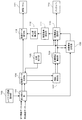
図1は、本実施例に係る液晶表示装置の機能構成の一例を示すブロック図である。
図1に示すように、液晶表示装置101は、第1画像入力部102、第2画像入力部103、画像判定部104、第1セレクタ105、第1合成部106、第2セレクタ107、画像解析部108、画像補正部109、第3セレクタ110、第2合成部111、第4セレクタ112、画像出力部113、液晶駆動部114、液晶パネル115、システム制御部116、不揮発性メモリ117、補正値決定部118、BL制御部119、バックライト120、電源ボタン121、操作ボタン群122などを有する。
(Overall configuration of liquid crystal display device)
FIG. 1 is a block diagram illustrating an example of a functional configuration of the liquid crystal display device according to the present embodiment.
As shown in FIG. 1, the liquid
第1画像入力部102と第2画像入力部103は、液晶表示装置101内に、共に表示する複数の画像を入力し、入力した複数の画像を画像判定部104に出力する。具体的には、第1画像入力部102と第2画像入力部103は、それぞれ、1つの画像(静止画または動画)を入力する。
The first
画像判定部104は、第1画像入力部102と第2画像入力部103から出力された画像毎に、静止画か動画かを判定する。具体的には、画像判定部104は、第1画像入力部102から出力された画像が静止画か動画かを判定し、第2画像入力部103から出力された画像が静止画か動画かを判定する。そして、画像判定部104は、判定結果をシステム制御部116に出力し、第1画像入力部102と第2画像入力部103から出力された複数の画像(2つの画像)を第1セレクタ105に出力する。
The
第1セレクタ105は、システム制御部116からの指示に応じて、画像判定部104から出力された複数の画像を、第1合成部106、第2セレクタ107、第3セレクタ110のいずれかに出力する。具体的には、複数の画像が静止画を含み、且つ、複数の画像をPinP表示(ピクチャ・イン・ピクチャ表示)する場合には、複数の画像のうちの静止画が第3セレクタ110に出力され、複数の画像のうちの動画が第2セレクタ107に出力される。それ以外の場合には、複数の画像は第1合成部106に出力される。
The
第1合成部106は、システム制御部116からの指示に応じて、入力された複数の画像を合成し、複数の画像を共に表示するための合成画像を生成する。そして、第1合成部106は、生成した合成画像を第2セレクタ107に出力する。
In response to an instruction from the
第2セレクタ107は、システム制御部116からの指示に応じて、入力された画像(
第1合成部106から入力された合成画像、または、第1セレクタ105から入力された動画)を、画像解析部108に出力する。
In response to an instruction from the
The combined image input from the first combining
画像解析部108は、システム制御部116からの指示に応じて、画面を分割して得られる分割領域毎に、その分割領域に表示される画像(第2セレクタ107から入力された画像)の特徴量を取得する。そして、画像解析部108は、分割領域毎の特徴量を、補正値決定部118に出力する。また、画像解析部108は、第2セレクタ107から入力された画像を、画像補正部109に出力する。
The
画像補正部109は、システム制御部116からの指示に応じて、画像解析部108から入力された画像を補正する。そして、画像補正部109は、補正後の画像(補正をしない場合には画像解析部108から入力された画像)を第3セレクタ110に出力する。
The
第3セレクタ110は、システム制御部116からの指示に応じて、入力された画像(画像補正部109から入力された画像(動画または合成画像)、または、第1セレクタ105から入力された静止画)を、第2合成部111と第4セレクタ112のいずれかに出力する。具体的には、画像補正部109から入力された合成画像は、第4セレクタ112に出力される。画像補正部109から入力された動画、及び、第1セレクタ105から入力された静止画は、第2合成部111に出力される。
The
第2合成部111は、システム制御部116からの指示に応じて、第3セレクタ110から入力された複数の画像(静止画と動画)を合成し、複数の画像を共に表示するための合成画像を生成する。そして、第2合成部111は、生成した合成画像を第4セレクタ112に出力する。
The
第4セレクタ112は、システム制御部116からの指示に応じて、入力された画像(第3セレクタ110から入力された合成画像、または、第2合成部111から入力された合成画像)を、画像出力部113に出力する。
The
画像出力部113は、システム制御部116からの指示に応じて、第4セレクタ112から入力された合成画像のデータを、液晶パネル115の表示解像度、表示色数、リフレッシュレートに適した表示データに変換する。そして、画像出力部113は、変換後のデータ(表示データ)を液晶駆動部114に出力する。
In response to an instruction from the
液晶駆動部114は、画像出力部113から入力された表示データを、液晶パネル115の透過率を制御する制御信号に変換する。そして、液晶駆動部114は、制御信号を液晶パネル115に出力する。
The liquid
液晶パネル115は、バックライト120からの光を透過することにより、画面上に画像を表示する表示パネルである。液晶パネル115は、液晶駆動部114から入力された制御信号に応じて透過率(バックライト120から照光される光に対する、液晶パネル115を透過する光の割合)が変化する複数の画素を有する。
The
システム制御部116は、液晶表示装置101が有する各機能を制御する。
不揮発性メモリ117は、液晶表示装置101の動作に関わる複数の情報を記憶している。
The
The
補正値決定部118とBL制御部119は、システム制御部116からの指示に応じて、分割領域毎の発光輝度(バックライト120の発光輝度)を設定する。本実施例では、表示する画像、及び、画像解析部108で取得された分割領域毎の特徴量に基づいて、分
割領域毎の発光輝度が設定される。具体的には、複数の画像が静止画を含み、且つ、複数の画像をPinP表示する場合には、少なくとも一部に静止画が表示される複数の分割領域に対して同じ発光輝度が設定され、静止画が表示されない分割領域に対して分割領域毎の特徴量に基づく発光輝度が設定される。それ以外の場合には、分割領域毎に、分割領域毎の特徴量に基づく発光輝度が設定される。
The correction
補正値決定部118は、システム制御部116からの指示に応じて、画像補正部109で動画を補正するために使用する画像データ補正値と、BL制御部119で分割領域毎の発光輝度を設定する際に使用するBL発光データ補正値とを決定する。そして、補正値決定部118は、画像データ補正値を画像補正部109に出力し、BL発光データ補正値をBL制御部119に出力する。
In accordance with an instruction from the
BL制御部119は、システム制御部116からの指示に応じて、分割領域毎の発光輝度を設定する。
The
バックライト120は、分割領域毎に、設定された発光輝度で発光する。具体的には、バックライト120は、液晶パネル115の背面側に設けられており、液晶パネル115の背面に光を照射する。バックライト120は、分割領域毎に光源を有する。各分割領域の光源は、設定された発光輝度で発光するように、個別に制御可能である。
The
(バックライトの構造と基本制御について)
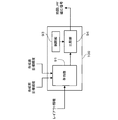
図2に、本実施例に係るバックライト120の構成の一例を示す。
本実施例では、図2に示すように、バックライト120は、水平方向32個×垂直方向20個の計640個の分割領域に対応する640個のLED制御エリアからなる。各分割領域(各LED制御エリア)には光源(図2の例では4つの白色LED)が設けられている。各分割領域の光源は、個別に制御することができる。
なお、分割領域の数は640個に限らない。例えば、分割領域の数は、水平方向16個×垂直方向10個の計160個であってもよいし、水平方向40個×垂直方向25個の計1000個であってもよいし、水平方向1個×垂直方向8個の計8個であってもよいし、水平方向12個×垂直方向1個の計12個であってもよい。
(Backlight structure and basic control)
FIG. 2 shows an example of the configuration of the
In the present embodiment, as shown in FIG. 2, the
The number of divided areas is not limited to 640. For example, the number of divided regions may be 160 in total, 16 in the horizontal direction × 10 in the vertical direction, or 1000 in total in the horizontal direction of 40 × 25 in the vertical direction. There may be 8 in total, 1 x 8 in the vertical direction, or 12 in total, 12 in the horizontal direction x 1 in the vertical direction.
図3に、1つの分割領域の光源の一例を示す。
本実施例では、図3に示すように、1つの分割領域の光源として、直列に接続された4つの白色LEDが使用される。また、各分割領域には、その分割領域の光源に電流を流して、当該光源を発光させるLEDドライバ301が設けられている。
LEDドライバ301は、BL制御部119から入力されたPWM制御データに応じて、PWM(Pulse Width Modulation)制御を行い、光源(4つのLED)に電流を流す。PWM制御データは、LEDドライバ301が光源に流す電流量(当該光源に電流を流す時間(パルス幅))を表す。
FIG. 3 shows an example of a light source in one divided area.
In this embodiment, as shown in FIG. 3, four white LEDs connected in series are used as the light source of one divided region. Each divided region is provided with an
The
BL制御部119は、発光輝度を表すBL発光データ(0〜4095の値)を決定し、BL発光データをPWM制御データに変換する。そして、BL制御部119は、PWM制御データをLEDドライバ301に出力する。本実施例では、発光輝度が高いほどBL発光データの値が大きいものとする。
なお、BL発光データの値の範囲は、0〜4095に限らない。BL発光データの値の範囲は、0〜4095より狭くてもよいし、広くてもよい。
The
Note that the range of the value of the BL light emission data is not limited to 0 to 4095. The range of the value of the BL light emission data may be narrower than 0 to 4095 or may be wide.
本実施例では、分割領域と、その分割領域のバックライトを所定の発光輝度で発光させるためのBL発光データとの対応関係を表すテーブル(BL発光データテーブル)が、不揮発性メモリ117に予め記憶されている。BL発光データテーブルは、液晶表示装置1
01の製造段階において、液晶表示装置101とは異なる装置(不図示)によって作成される。例えば、BL発光データテーブルは、画面上の輝度ムラが最小となるようにBL発光データを調整することにより作成される。
本実施例では、不揮発性メモリ117に、発光輝度20〜200cd/m2を10等分して得られる10個の発光輝度(間隔が20cd/m2の10個の発光輝度)に対応する10個のBL発光データテーブルが予め記憶されている。また、不揮発性メモリ117には、上記10個の発光輝度である10個のバックライト輝度値が予め記憶されている。
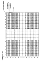
図4(a),4(b)にBL発光データテーブルの一例を示す。
図4(a)は、バックライト全体(各分割領域のバックライト)を発光輝度100cd/m2で発光させるためのBL発光データの一例である。
図4(b)は、バックライト全体(各分割領域のバックライト)を発光輝度200cd/m2で発光させるためのBL発光データの一例である。
図4(a),4(b)において、分割領域間でBL発光データが異なるのは、LED毎に発光特性が異なるためである。
なお、予め用意するBL発光データテーブルの数は10個に限らない。予め用意するBL発光データテーブルの数は10個より少なくてもよいし、多くてもよい。予め用意するBL発光データテーブルの数は1個でもよい。
In the present embodiment, a table (BL light emission data table) representing a correspondence relationship between a divided region and BL light emission data for causing the backlight of the divided region to emit light with a predetermined light emission luminance is stored in the
In the manufacturing stage 01, the liquid
In the present embodiment, the
4A and 4B show an example of the BL light emission data table.
FIG. 4A is an example of BL light emission data for causing the entire backlight (backlight of each divided region) to emit light with an emission luminance of 100 cd /
FIG. 4B is an example of BL light emission data for causing the entire backlight (backlight of each divided region) to emit light with a light emission luminance of 200 cd /
In FIGS. 4 (a) and 4 (b), the reason why the BL light emission data differs between the divided regions is that the light emission characteristics are different for each LED.
The number of BL light emission data tables prepared in advance is not limited to ten. The number of BL light emission data tables prepared in advance may be less than 10 or more. The number of BL light emission data tables prepared in advance may be one.
BL制御部119は、システム制御部116からの点灯制御要求に応じて、不揮発性メモリ117からバックライト輝度値(発光輝度)を取得する。バックライト輝度値は、デフォルト値、ユーザに指定された値、表示する画像の種類等に応じて設定された値である。
次に、BL制御部119は、バックライト輝度値に対応するBL発光データテーブルを、不揮発性メモリ117から取得する。例えば、バックライト輝度値が「100cd/m2」の場合には、図4(a)に示したBL発光データが取得される。
そして、BL制御部119は、分割領域毎に、補正値決定部118から入力されたBL発光データ補正値を用いて、取得したBL発光データテーブルにおけるBL発光データを補正する。本処理により、各分割領域の発光輝度が決定(設定)される。
次に、BL制御部119は、分割領域毎に、補正後のBL発光データをPWM制御データに変換する。例えば、補正後のBL発光データが0の場合、対応する分割領域のバックライト(光源)を発光させないために、補正後のBL発光データは、電流量(電流を流す時間が0)のPWM制御データに変換される。補正後のBL発光データが4095の場合、対応する分割領域のバックライト(光源)を最大発光輝度で発光させるために、補正後のBL発光データは、電流量が最大値(電流を流す時間が最大値)のPWM制御データに変換される。
そして、BL制御部119は、分割領域毎に、その分割領域のPWM制御データを、当該分割領域のLEDドライバ301に出力する。
The
Next, the
Then, the
Next, the
And
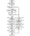
(液晶表示装置の動作について)
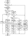
図5は、本実施例に係る液晶表示装置101の動作の一例を示すフローチャートである。図5は、複数の画像を共に表示する場合の動作の一例を示す。図5の動作は、電源オン要求、複数の画像を共に表示する表示モードへ変更する表示モード変更要求などの入力をシステム制御部116が検出した場合に開始される。電源オン要求は、ユーザが電源ボタン121を操作することにより入力される。表示モード変更要求は、ユーザが操作ボタン群122を操作することにより入力される。
(Operation of the liquid crystal display device)
FIG. 5 is a flowchart illustrating an example of the operation of the liquid
まず、画像判定部104が、第1画像入力部102から入力された画像が静止画か動画かを判定し、第2画像入力部103から入力された画像が静止画か動画かを判定する(S501)。例えば、複数フレーム間の画素値を比較することにより、画像が静止画か動画かが判定される。画像判定部104は、判定結果をシステム制御部116に出力し、第1
画像入力部102と第2画像入力部103から入力された2つの画像を第1セレクタ105に出力する。
First, the
Two images input from the
次に、システム制御部116が、画像判定部104の判定結果から、共に表示する複数の画像(第1画像入力部102と第2画像入力部103から入力された2つの画像)に静止画が含まれているか否かを判定する(S502)。複数の画像に静止画が含まれている場合にはS503に処理が進められ、複数の画像に静止画が含まれていない場合にはS510に処理が進められる。
Next, based on the determination result of the
S503では、システム制御部116が、不揮発性メモリ117から表示レイアウト情報を取得する。表示レイアウト情報は、表示形式の種類、各画像の表示領域情報などを含む。表示形式の種類としては、PinP表示、PoutP表示(ピクチャ・アウト・ピクチャ表示)などがある。表示領域情報は、画像が表示される画面上の領域(表示領域)を表す情報である。表示領域情報は、例えば、表示領域の始点と終点、表示領域の位置とサイズなどである。なお、1つの表示レイアウト情報が用意されていてもよいし、複数の表示レイアウト情報が用意されていてもよい。複数の表示レイアウト情報が用意されている場合には、デフォルトの表示レイアウト情報が取得されてもよいし、ユーザ操作や表示する画像の種類などに応じた表示レイアウト情報が取得されてもよい。
In step S <b> 503, the
次に、システム制御部116が、S503で取得した表示レイアウト情報に基づいて、表示形式がPinP表示か否かを判定する(S504)。表示形式がPinP表示の場合にはS505に処理が進められ、PinP表示でない場合にはS510に処理が進められる。
Next, the
(複数の画像が静止画を含み、且つ、複数の画像をPinP表示する場合)
S505では、システム制御部116が、画像判定部104の判定結果に基づいて、画像判定部104から入力された2つの画像のうち、静止画が第3セレクタ110に出力され、動画が画像解析部108に出力されるように第1セレクタ105を制御する。画像解析部108は、分割領域毎に、その分割領域に表示される動画(第1セレクタ105から入力された動画)の特徴量を取得する。本実施例では、特徴量として平均輝度レベル(APL)が取得される。そして、画像解析部108は、分割領域毎の特徴量を、補正値決定部118に出力する。また、画像解析部108は、第1セレクタ105から入力された動画を画像補正部109に出力する。
なお、画像判定部104から入力された2つの画像がいずれも静止画である場合には、当該2つの画像は第1セレクタ105から第3セレクタ110へ送られる。
(When multiple images include still images and multiple images are displayed in PinP)
In S <b> 505, the
Note that when the two images input from the
次に、補正値決定部118が、画像解析部108から入力された分割領域毎の特徴量と、システム制御部116から入力された表示レイアウト情報に基づいて、BL発光データ補正値と画像データ補正値を決定する(S506)。
Next, the correction
S506の処理について詳しく説明する。
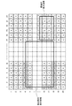
図6は、S506の処理の一例を示すフローチャートである。図7は、静止画と動画をPinP表示する場合の、静止画と動画の表示領域と、分割領域との関係の一例を示す図である。
まず、補正値決定部118が、表示レイアウト情報に基づいて、処理対象(補正値の算出対象)の分割領域が静止画領域、動画領域、混在領域のうちのどの領域かを判定する(S601)。静止画領域は静止画のみが表示される分割領域である。動画領域は動画のみが表示される分割領域である。混在領域は静止画と動画の両方が表示される分割領域である。
図7において、破線で示す領域は分割領域である。図7において、符号aは静止画領域
を示し、符号bは動画領域を示し、符号cは混在領域を示す。
処理対象の分割領域が静止画領域である場合には、S602に処理が進められる。処理対象の分割領域が動画領域である場合には、S603に処理が進められる。処理対象の分割領域が混在領域である場合には、S604に処理が進められる。
The process of S506 will be described in detail.
FIG. 6 is a flowchart illustrating an example of the process of S506. FIG. 7 is a diagram illustrating an example of a relationship between a still image / moving image display area and a divided area when a still image / moving image is displayed in PinP.
First, the correction
In FIG. 7, a region indicated by a broken line is a divided region. In FIG. 7, the symbol a indicates a still image region, the symbol b indicates a moving image region, and the symbol c indicates a mixed region.
If the division area to be processed is a still image area, the process proceeds to S602. If the division area to be processed is a moving image area, the process proceeds to S603. If the division area to be processed is a mixed area, the process proceeds to S604.
S602では、補正値決定部118が、処理対象の分割領域(静止画領域)のBL発光データ補正値を決定する。本実施例では、静止画領域のBL発光データの補正を行なわないため、BL発光データ補正値が「1」とされる。その後、S607に処理が進められる。
In S602, the correction
S603では、補正値決定部118が、処理対象の分割領域(動画領域)のBL発光データ補正値を決定する。
本実施例では、動画領域のBL発光データを、動画の特徴量に基づくBL発光データにするBL発光データ補正値が決定される。例えば、暗い画像が表示される動画領域の発光輝度が、明るい画像が表示される分割領域の発光輝度よりも低くなるように、BL発光データ補正値が決定される。
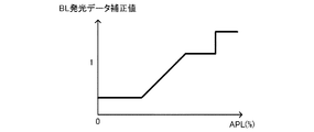
具体的には、処理対象の分割領域(動画領域)の特徴量であるAPLと、不揮発性メモリ117に記憶されているBL発光データ補正値テーブルとから、BL発光データ補正値が決定される。BL発光データ補正値テーブルは、APLとBL発光データ補正値の関係を示すテーブル(または関数)である。BL発光データ補正値テーブルの一例を図8に示す。図8の横軸はAPLを示し、縦軸はBL発光データ補正値を示す。図8に示すように、本実施例では、APLが大きいときのほうが、APLが小さいときよりも大きいBL発光データ補正値が得られる。また、図8の例では、BL発光データ補正値は、1より小さい値から1より大きい値までを取りうる。
なお、図8の例では、BL発光データ補正値テーブルには、APLの変化に対してBL発光データ補正値が変化しない部分が存在するが、そのような部分は存在しなくてもよい。また、図8の例では、APLの変化に対してBL発光データ補正値が線形に変化しているが、APLの変化に対してBL発光データ補正値が非線形に変化してもよい。APLの変化に対してBL発光データ補正値が段階的に変化してもよい。
In step S <b> 603, the correction
In this embodiment, a BL light emission data correction value for determining the BL light emission data in the moving image area as the BL light emission data based on the feature amount of the moving image is determined. For example, the BL light emission data correction value is determined so that the light emission luminance of a moving image area where a dark image is displayed is lower than the light emission luminance of a divided area where a bright image is displayed.
Specifically, the BL light emission data correction value is determined from the APL that is the feature amount of the division area (moving image area) to be processed and the BL light emission data correction value table stored in the
In the example of FIG. 8, the BL light emission data correction value table includes a portion where the BL light emission data correction value does not change with respect to a change in APL, but such a portion may not exist. In the example of FIG. 8, the BL light emission data correction value changes linearly with respect to the change in APL, but the BL light emission data correction value may change non-linearly with respect to the change in APL. The BL light emission data correction value may change stepwise with respect to the change of APL.
S604では、補正値決定部118が、処理対象の分割領域(混在領域)のBL発光データ補正値を決定する。本実施例では、混在領域のBL発光データの補正を行なわないため、BL発光データ補正値が「1」とされる。その後、S605,S606の処理が行われ、S607に処理が進められる。
In S604, the correction
S605,S606では、補正値決定部118が、画像データ補正値を決定する。画像データ補正値は、特徴量に基づく発光輝度でバックライトを発光させたときと、設定した発光輝度でバックライトを発光させたときとで、混在領域内における動画の画面上の明るさが変化しないように、動画を補正するための補正値である。混在領域内(静止画と動画の両方が表示される分割領域内)における動画の領域は、例えば、図7の符号c−2で示す領域である。図7の符号c−1で示す領域は、混在領域内における静止画の領域である。
In S605 and S606, the correction
S605では、補正値決定部118が、処理対象の分割領域(混在領域)に対して、動画のみを表示する(静止画を表示しない)と仮定したときのBL発光データ補正値(理想BL発光データ補正値)を決定する。理想BL発光データ補正値は、動画領域のBL発光データ補正値の決定方法と同様に、処理対象の分割領域の特徴量(動画の特徴量)であるAPLと、不揮発性メモリ117に記憶されているBL発光データ補正値テーブル(図8)とから、決定される。
In S <b> 605, the BL light emission data correction value (ideal BL light emission data) when the correction
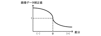
S606では、補正値決定部118が、処理対象の分割領域(混在領域)内の動画の各画素に適用する画像データ補正値を決定する。具体的には、画像データ補正値は、S604で決定したBL発光データ補正値と、S605で決定した理想BL発光データ補正値との差分、及び、不揮発性メモリ117に記憶されている画像データ補正値テーブルを用いて決定される。画像データ補正値テーブルは、BL発光データ補正値の差分(S604で決定したBL発光データ補正値−S605で決定した理想BL発光データ補正値)と画像データ補正値の関係を示すテーブル(または関数)である。画像データ補正値テーブルの一例を図9に示す。図9の横軸はBL発光データ補正値の差分を示し、縦軸は画像データ補正値を示す。図9に示すように、本実施例では、差分が大きいときのほうが、差分が小さいときよりも大きい画像データ補正値が得られる。また、図9に示すように、差分が0のときに、BL発光データ補正値は1となる。
なお、図9の例では、差分の変化に対して画像データ補正値が非線形に変化しているが、差分の変化に対して画像データ補正値が線形に変化してもよい。差分の変化に対して画像データ補正値が段階的に変化してもよい。また、画像データ補正値テーブルには、差分の変化に対して画像データ補正値が変化しない部分が存在していてもよい。
In S <b> 606, the correction
In the example of FIG. 9, the image data correction value changes nonlinearly with respect to the difference change, but the image data correction value may change linearly with respect to the difference change. The image data correction value may change stepwise as the difference changes. In the image data correction value table, there may be a portion where the image data correction value does not change with respect to a difference change.
S607では、補正値決定部118が、全ての分割領域についてS601〜S606の処理が行われたか否かを判定する。S601〜S606の処理が行われていない分割領域(未処理の分割領域)がある場合には、補正値決定部118が、処理対象の分割領域を未処理の分割領域に切り替え、S601に処理が戻される。全ての分割領域についてS601〜S606の処理が行われた場合には、S608に処理が進められる。
In S607, the correction
S608では、補正値決定部118が、分割領域毎のBL発光データ補正値をBL制御部119に出力する。
S609では、補正値決定部118が、混在領域毎(混在領域内の動画の画素毎)の画像データ補正値を画像補正部109に出力する。
In S <b> 608, the correction
In step S <b> 609, the correction
図5の説明に戻る。
S506の次に、BL制御部119が、分割領域毎に、BL発光データテーブルから決定したBL発光データに対し、補正値決定部118から入力されたBL発光データ補正値を乗算する(S507;BL発光データの補正)。それにより、分割領域毎の発光輝度が決定(設定)される。BL制御部119は、分割領域毎に、補正後のBL発光データをPWM制御データに変換する。
Returning to the description of FIG.
Following S506, the
次に、画像補正部109が、画像解析部108から入力された動画に、補正値決定部118から入力された画像データ補正値を乗算する(S508;動画の補正)。画像補正部109は、補正後の動画を第3セレクタ110に出力する。
なお、共に表示する2つの画像がいずれも静止画である場合には、画像解析部108と画像補正部109に動画は入力されず、S508の処理は行われない。
Next, the
If both of the two images displayed together are still images, no moving image is input to the
そして、システム制御部116が、画像補正部109から入力された動画と、第1セレクタ105から入力された静止画とが、第2合成部111に出力されるように第3セレクタ110を制御する。さらに、システム制御部116は、表示レイアウト情報に基づいて、入力された静止画と動画をPinP表示するための合成画像が生成されるように、第2合成部111を制御する(S509)。第2合成部111は、生成した合成画像を画像出力部113に出力する。
なお、共に表示する2つの画像がいずれも静止画である場合には、画像補正部109から第3セレクタ110に動画は送られず、第1セレクタ105から第3セレクタ110に2つの静止画が送られる。そして、2つの静止画が第3セレクタ110から第2合成部111へ送られ、当該2つの静止画をPinP表示するための合成画像が生成される。
Then, the
If both the two images displayed together are still images, no moving image is sent from the
そして、BL制御部119が、分割領域毎のPWM制御データをバックライト120に送信する。それにより、バックライト120は、分割領域毎に設定された発光輝度で発光する。また、画像出力部113が、合成画像から表示データを生成し、表示データを液晶駆動部114に出力する。そして、液晶駆動部114が、画像出力部113から入力された表示データを、液晶パネル115の透過率を制御する制御信号に変換し、制御信号を液晶パネル115に出力する。それにより、液晶パネル115の透過率が制御される。
透過率の制御と、バックライトの発光とを所定のタイミングで行うことにより、画面に画像が表示される。
Then, the
An image is displayed on the screen by performing transmittance control and backlight emission at a predetermined timing.
(複数の画像が静止画を含まない場合、又は、複数の画像をPinP表示しない場合)
S510では、システム制御部116が、画像判定部104から入力された2つの画像が第1合成部106に出力されるように第1セレクタ105を制御する。さらに、システム制御部116は、表示レイアウト情報に基づいて、入力された2つの画像を共に表示するための合成画像が生成されるように、第1合成部106を制御する。第1合成部106は、生成した合成画像を第2セレクタ107に出力する。
(When multiple images do not contain still images or when multiple images are not displayed in PinP)
In step S <b> 510, the
次に、システム制御部116が、第1合成部106から入力された合成画像が画像解析部108に出力されるように第2セレクタ107を制御する。画像解析部108は、分割領域毎に、その分割領域に表示される合成画像(第2セレクタ107から入力された合成画像)の特徴量を取得する(S511)。そして、画像解析部108は、分割領域毎の特徴量を、補正値決定部118に出力する。また、画像解析部108は、第2セレクタ107から入力された合成画像を画像補正部109に出力する。
Next, the
そして、補正値決定部118が、画像解析部108から入力された分割領域毎の特徴量に基づいて、BL発光データ補正値を決定する(S512)。分割領域毎のBL発光データ補正値は、動画領域のBL発光データ補正値の決定方法と同様に、処理対象の分割領域の特徴量であるAPLと、不揮発性メモリ117に記憶されているBL発光データ補正値テーブル(図8)とから、決定される。
Then, the correction
次に、BL制御部119が、分割領域毎に、BL発光データテーブルから決定したBL発光データに対し、補正値決定部118から入力されたBL発光データ補正値を乗算する(S513;BL発光データの補正)。それにより、分割領域毎の発光輝度が決定(設定)される。BL制御部119は、分割領域毎に、補正後のBL発光データをPWM制御データに変換する。
Next, the
そして、BL制御部119が、分割領域毎のPWM制御データをバックライト120に送信する。それにより、バックライト120は、分割領域毎に設定された発光輝度で発光する。また、画像補正部109が、画像解析部108から入力された合成画像を第3セレクタ110に出力する。第3セレクタ110が、画像補正部109から入力された合成画像を第4セレクタ112に出力する。第4セレクタ112が、第3セレクタ110から入力された合成画像を画像出力部113に出力する。画像出力部113が、合成画像から表示データを生成し、表示データを液晶駆動部114に出力する。そして、液晶駆動部114が、画像出力部113から入力された表示データを、液晶パネル115の透過率を制御する制御信号に変換し、制御信号を液晶パネル115に出力する。それにより、液晶パネル115の透過率が制御される。
透過率の制御と、バックライトの発光とを所定のタイミングで行うことにより、画面に画像が表示される。
Then, the
An image is displayed on the screen by performing transmittance control and backlight emission at a predetermined timing.
以上述べたように、本実施例によれば、静止画と動画をPinP表示する場合に、少な
くとも一部に静止画が表示される複数の分割領域に対して、同じ発光輝度が設定され、静止画が表示されない分割領域に対して、分割領域毎の特徴量に基づく発光輝度が設定される。それにより、静止画と共に動画を表示する場合(静止画と動画をPinP表示する場合)に、静止画の視認性の低下を抑制し、且つ、動画のコントラストを向上することができる。
また、本実施例によれば、静止画と動画をPinP表示する場合に、特徴量に基づく発光輝度でバックライトを発光させたときと、設定された発光輝度でバックライトを発光させたときとで、混在領域内における動画の画面上の明るさが変化しないように、動画が補正される。それにより、少なくとも一部に静止画が表示される複数の分割領域に対して同じ発光輝度を設定することによる動画の画質の劣化を抑制することができる。
As described above, according to the present embodiment, when a still image and a moving image are displayed in PinP, the same light emission luminance is set for a plurality of divided areas where the still image is displayed at least partially, The light emission luminance based on the feature amount for each divided region is set for the divided region where no image is displayed. Thereby, when displaying a moving image with a still image (when displaying a still image and a moving image by PinP), the fall of the visibility of a still image can be suppressed and the contrast of a moving image can be improved.
Further, according to the present embodiment, when a still image and a moving image are displayed in PinP, the backlight is emitted with the emission luminance based on the feature amount, and the backlight is emitted with the set emission luminance. Thus, the moving image is corrected so that the brightness of the moving image on the screen in the mixed area does not change. Thereby, it is possible to suppress deterioration in the image quality of a moving image by setting the same light emission luminance for a plurality of divided regions in which a still image is displayed at least in part.
<実施例2>
本発明の実施例2に係る表示装置及びその制御方法について以下に説明する。
実施例1では、静止画と動画をPinP表示する場合に静止画の画質の劣化を抑制する構成について説明した。本実施例では、静止画と動画をPoutP表示する場合にも静止画の画質の劣化を抑制することのできる構成について説明する。
本実施例に係る液晶表示装置の全体構成は、実施例1(図1)と同様のため、その説明は省略する。
また、本実施例に係るバックライト120の構造と基本制御も、実施例1と同様のため、その説明は省略する。
<Example 2>
A display device and a control method thereof according to
In the first embodiment, a configuration has been described in which degradation of image quality of a still image is suppressed when a still image and a moving image are displayed in PinP. In the present embodiment, a description will be given of a configuration that can suppress degradation of the image quality of a still image even when a still image and a moving image are displayed in PoutP.
Since the overall configuration of the liquid crystal display device according to the present embodiment is the same as that of the first embodiment (FIG. 1), description thereof is omitted.
Further, the structure and basic control of the
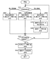
(液晶表示装置の動作について)
図10は、本実施例に係る液晶表示装置101の動作の一例を示すフローチャートである。図10は、複数の画像を共に表示する場合の動作の一例を示す。図10の動作は、電源オン要求、表示モード変更要求などの入力をシステム制御部116が検出した場合に開始される。
(Operation of the liquid crystal display device)
FIG. 10 is a flowchart illustrating an example of the operation of the liquid
図10のS501〜S503の処理は、それぞれ、図5のS501〜S503の処理と同様のため、その説明は省略する。
図10のS503の次に、システム制御部116が、S503で取得した表示レイアウト情報に基づいて、表示形式がPinP表示かPoutP表示かを判定する(S504)。表示形式がPinP表示の場合にはS505に処理が進められ、表示形式がPoutP表示の場合にはS1001に処理が進められる。
The processes in S501 to S503 in FIG. 10 are the same as the processes in S501 to S503 in FIG.
Next to S503 in FIG. 10, the
(複数の画像が静止画を含み、且つ、複数の画像をPinP表示する場合)
図10のS505〜S509の処理は、それぞれ、図5のS505〜S509の処理と同様のため、その説明は省略する。
(When multiple images include still images and multiple images are displayed in PinP)
The processes in S505 to S509 in FIG. 10 are the same as the processes in S505 to S509 in FIG.
(複数の画像が静止画を含み、且つ、複数の画像をPoutP表示する場合)
図10のS1001では、システム制御部116が、S503で取得した表示レイアウト情報(PoutP表示する各画像の表示領域情報)に基づいて、PoutP表示する2つの画像の間隔を算出する。換言すれば、PoutP表示する2つの画像が表示される2つの領域(画面上の領域)の間隔が算出される。
(When multiple images include still images and multiple images are displayed in PoutP)
In S1001 of FIG. 10, the
次に、システム制御部116が、PoutP表示する2つの画像の両方が表示される分割領域が存在するか否かを判定する(S1002)。具体的には、システム制御部116は、S1001で算出した間隔Laが1つの分割領域のサイズLbよりも大きいか否かを判定する。間隔LaがサイズLbより大きい場合には、PoutP表示する2つの画像の両方が表示される分割領域が存在しないと判断され、S510に処理が進められる。間隔LaがサイズLb以下の場合には、PoutP表示する2つの画像の両方が表示される分
割領域が存在すると判断され、S1003に処理が進められる。
なお、PoutP表示する2つの画像の両方が表示される分割領域が存在するか否かの判定方法は上記方法(PoutP表示する2つの画像の間隔に基づく方法)に限らない。例えば、各分割領域を表す領域情報と、PoutP表示する2つの画像の表示領域情報とから、PoutP表示する2つの画像の両方が表示される分割領域が存在するか否かが判定されてもよい。
なお、バックライトの光源の特性(光の照射角度特性)やバックライトの拡散構造などに基づいて、サイズLbとして分割領域のサイズよりも大きいまたは小さいサイズが設定されてもよい。
Next, the
Note that the method for determining whether or not there is a divided region where both of the two images displayed in PoutP are displayed is not limited to the above method (a method based on the interval between the two images displayed in PoutP). For example, it may be determined whether or not there is a divided region in which both of the two images to be displayed in PoutP are displayed, from the region information representing each divided region and the display region information of the two images to be displayed in PoutP. .
It should be noted that a size larger or smaller than the size of the divided region may be set as the size Lb based on the characteristics of the light source of the backlight (light irradiation angle characteristics), the diffusion structure of the backlight, and the like.
S1003では、システム制御部116が、画像判定部104の判定結果に基づいて、画像判定部104から入力された2つの画像のうち、静止画が第3セレクタ110に出力され、動画が画像解析部108に出力されるように第1セレクタ105を制御する。画像解析部108は、分割領域毎に、その分割領域に表示される動画(第1セレクタ105から入力された動画)の特徴量を取得する。そして、画像解析部108は、分割領域毎の特徴量を、補正値決定部118に出力する。また、画像解析部108は、第1セレクタ105から入力された動画を画像補正部109に出力する。
In S1003, the
次に、補正値決定部118が、画像解析部108から入力された分割領域毎の特徴量と、システム制御部116から入力された表示レイアウト情報に基づいて、BL発光データ補正値と画像データ補正値を決定する(S1004)。
Next, the correction
S1004の処理について、図6のフローチャート、及び、図11,12を用いて詳しく説明する。
図11は、PoutP表示する静止画と動画の配置(画面上での配置)の一例を示す図である。図12は、図11のPoutP表示を行う場合における、静止画と動画の表示領域と、分割領域との関係を示す図である。
図11の例では、静止画と動画は間隔Laだけ離れて、配置されている。画面の領域のうち、静止画も動画も表示されない領域には、所定の背景画像が表示される。背景画像は、例えば、一様な色(黒やグレーなど)の画像である。
The process of S1004 will be described in detail with reference to the flowchart of FIG. 6 and FIGS.
FIG. 11 is a diagram illustrating an example of the arrangement (arrangement on the screen) of still images and moving images displayed in PoutP. FIG. 12 is a diagram illustrating the relationship between the still image and moving image display areas and the divided areas when the PoutP display of FIG. 11 is performed.
In the example of FIG. 11, the still image and the moving image are arranged apart from each other by an interval La. A predetermined background image is displayed in an area of the screen where no still image or moving image is displayed. The background image is, for example, an image with a uniform color (such as black or gray).
S601では、背景画像は静止画として扱って、実施例1と同様の処理が行われる。
図12において、破線で示す領域は分割領域である。図12において、符号aは静止画領域を示し、符号bは動画領域を示し、符号cは混在領域を示す。
処理対象の分割領域が静止画領域である場合には、S602に処理が進められる。処理対象の分割領域が動画領域である場合には、S603に処理が進められる。処理対象の分割領域が混在領域である場合には、S604に処理が進められる。
S602〜S609では、実施例1と同じ処理が行われる。
In S601, the background image is treated as a still image, and the same processing as in the first embodiment is performed.
In FIG. 12, a region indicated by a broken line is a divided region. In FIG. 12, a symbol a indicates a still image region, a symbol b indicates a moving image region, and a symbol c indicates a mixed region.
If the division area to be processed is a still image area, the process proceeds to S602. If the division area to be processed is a moving image area, the process proceeds to S603. If the division area to be processed is a mixed area, the process proceeds to S604.
In S602 to S609, the same processing as in the first embodiment is performed.
図10の説明に戻る。
S1004の次に、BL制御部119が、分割領域毎に、BL発光データテーブルから決定したBL発光データに対し、補正値決定部118から入力されたBL発光データ補正値を乗算する(S1005;BL発光データの補正)。それにより、分割領域毎の発光輝度が決定(設定)される。BL制御部119は、分割領域毎に、補正後のBL発光データをPWM制御データに変換する。
Returning to the description of FIG.
After S1004, the
次に、画像補正部109が、画像解析部108から入力された動画に、補正値決定部118から入力された画像データ補正値を乗算する(S1006;動画の補正)。画像補正部109は、補正後の動画を第3セレクタ110に出力する。
なお、共に表示する2つの画像がいずれも静止画である場合には、画像解析部108と
画像補正部109に動画は入力されず、S1006の処理は行われない。
Next, the
If both of the two images displayed together are still images, no moving image is input to the
そして、システム制御部116が、画像補正部109から入力された動画と、第1セレクタ105から入力された静止画とが、第2合成部111に出力されるように第3セレクタ110を制御する。さらに、システム制御部116は、表示レイアウト情報に基づいて、入力された静止画と動画をPoutP表示するための合成画像が生成されるように、第2合成部111を制御する(S1007)。第2合成部111は、生成した合成画像を画像出力部113に出力する。
なお、共に表示する2つの画像がいずれも静止画である場合には、画像補正部109から第3セレクタ110に動画は送られず、第1セレクタ105から第3セレクタ110に2つの静止画が送られる。そして、2つの静止画が第3セレクタ110から第2合成部111へ送られ、当該2つの静止画をPoutP表示するための合成画像が生成される。
Then, the
If both the two images displayed together are still images, no moving image is sent from the
(複数の画像が静止画を含まない場合、又は、間隔LaがサイズLbより大きい場合)
図10のS510〜S513の処理は、それぞれ、図5のS510〜S513の処理と同様のため、その説明は省略する。
(When multiple images do not include still images, or when the interval La is larger than the size Lb)
The processes in S510 to S513 in FIG. 10 are the same as the processes in S510 to S513 in FIG.
以上述べたように、本実施例によれば、静止画と動画をPinP表示する場合に、実施例1と同様に、静止画の視認性の低下を抑制し、且つ、動画のコントラストを向上することができる。
また、本実施例によれば、静止画と動画をPoutP表示する場合に、少なくとも一部に静止画が表示される複数の分割領域に対して、同じ発光輝度が設定され、静止画が表示されない分割領域に対して、分割領域毎の特徴量に基づく発光輝度が設定される。それにより、静止画と動画をPoutP表示する場合に、静止画の視認性の低下を抑制し、且つ、動画のコントラストを向上することができる。
また、本実施例によれば、静止画と動画の両方が表示される分割領域が存在しない場合には、分割領域毎に、分割領域毎の特徴量に基づく発光輝度が設定される。静止画と動画の両方が表示される分割領域が存在しない場合には、動画の輝度変化によって静止画が表示される分割領域の発光輝度が変化することはないため、静止画の画質の劣化も発生しない。そのため、静止画と動画の両方が表示される分割領域が存在する場合に、分割領域毎に、分割領域毎の特徴量に基づく発光輝度を設定することにより、静止画と動画の両方のコントラストを向上することができる。
As described above, according to the present embodiment, when a still image and a moving image are displayed in PinP, similarly to the first embodiment, a reduction in the visibility of the still image is suppressed and the contrast of the moving image is improved. be able to.
Further, according to the present embodiment, when PoutP display of still images and moving images, the same emission luminance is set for a plurality of divided areas where still images are displayed at least partially, and still images are not displayed. The light emission luminance based on the feature amount for each divided region is set for the divided region. Thereby, when still images and moving images are displayed in PoutP, it is possible to suppress a reduction in the visibility of the still images and to improve the contrast of the moving images.
Further, according to the present embodiment, when there is no divided area where both a still image and a moving image are displayed, the light emission luminance based on the feature amount for each divided area is set for each divided area. If there is no divided area where both still images and moving images are displayed, the luminance of the divided areas where still images are displayed will not change due to changes in the luminance of moving images. Does not occur. Therefore, when there is a divided area where both still images and moving images are displayed, the contrast of both the still image and moving image can be reduced by setting the light emission luminance based on the feature amount of each divided area for each divided area. Can be improved.
<実施例3>
本発明の実施例3に係る表示装置及びその制御方法について以下に説明する。
実施例1,2では、静止画と動画をPinP表示する場合、静止画と動画をPoutP表示する場合に静止画の画質劣化を抑制する構成について説明した。本実施例では、複数の静止画を共に表示し静止画の表示位置を変更する場合にも静止画の画質の劣化を抑制することのできる構成について説明する。
<Example 3>
A display device and a control method thereof according to
In the first and second embodiments, the configuration for suppressing the deterioration of the image quality of the still image when the still image and the moving image are displayed in PinP and the still image and the moving image are displayed in PoutP has been described. In the present embodiment, a description will be given of a configuration that can suppress degradation of image quality of a still image even when a plurality of still images are displayed together and the display position of the still image is changed.
本実施例に係る液晶表示装置の全体構成は、実施例1(図1)と同様のため、その説明は省略する。
また、本実施例に係るバックライト120の構造と基本制御も、実施例1と同様のため、その説明は省略する。
Since the overall configuration of the liquid crystal display device according to the present embodiment is the same as that of the first embodiment (FIG. 1), description thereof is omitted.
Further, the structure and basic control of the
(液晶表示装置の動作について)
図16は、本実施例に係る液晶表示装置101の動作の一例を示すフローチャートである。図16は、複数の画像を共に表示する場合の動作の一例を示す。図16の動作は、電源オン要求、表示モード変更要求、表示位置変更要求などの入力をシステム制御部116が検出した場合に開始される。電源オン要求は、ユーザが電源ボタン121を操作するこ
とにより入力される。表示モード変更要求は、ユーザが操作ボタン群122を操作することにより入力される。画像の表示位置を変更する表示位置変更要求は、ユーザが操作ボタン群122を操作することにより入力される。
(Operation of the liquid crystal display device)
FIG. 16 is a flowchart illustrating an example of the operation of the liquid
図16のS501〜S503の処理は、それぞれ、図10のS501〜S503の処理と同様のため、その説明は省略する。
図16のS503の次に、システム制御部116が、S503で取得した表示レイアウト情報に基づいて、表示形式がPinP表示かPoutP表示かを判定する(S504)。表示形式がPinP表示の場合にはS1601に処理が進められ、表示形式がPoutP表示の場合にはS1001に処理が進められる。
The processes in S501 to S503 in FIG. 16 are the same as the processes in S501 to S503 in FIG.
After S503 in FIG. 16, the
表示形式がPinP表示の場合、システム制御部116が、画像判定部104の判定結果から、共に表示する複数の画像(第1画像入力部102と第2画像入力部103から入力された2つの画像)に動画が含まれているか否かを判定する(S1601)。複数の画像に動画が含まれている場合にはS505に処理が進められ、複数の画像に動画が含まれていない場合にはS1602に処理が進められる。
When the display format is PinP display, the
(複数の画像が動画と静止画を含み、且つ、複数の画像をPinP表示する場合)
図16のS505〜S509の処理は、それぞれ、図10のS505〜S509の処理と同様のため、その説明は省略する。
(When multiple images include moving images and still images, and multiple images are displayed in PinP)
The processes in S505 to S509 in FIG. 16 are the same as the processes in S505 to S509 in FIG.
(複数の画像が静止画のみであり、且つ、複数の画像をPinP表示する場合)
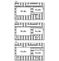
図17(a)〜17(c)は、2つの静止画をPinP表示する場合の配置(画面上での配置)の一例を示す図である。図17(a)〜17(c)では、静止画bの表示位置が互いに異なる。本実施例に係る液晶表示装置101では、ユーザは、操作ボタン群122を操作することにより、画像の表示位置を変更することができる。本実施例では、そのようなユーザ操作により、2つの静止画が、図17(a)〜17(c)に示した表示位置でPinP表示される例を説明する。
複数の静止画をPinP表示する場合、静止画の表示位置を変更すると、表示位置が変更された静止画周辺の他の静止画の表示にちらつきが生じる。例えば、静止画bの表示位置を変更すると、静止画b周辺の静止画aの表示にちらつきが生じる。そこで、本実施例では、複数の静止画をPinP表示する場合には、ローカルディミング制御を行わず、各分割領域に同じ発光輝度を設定する。具体的には、S1602では以下の処理が行われる。システム制御部116が、画像判定部104から入力された複数(本実施例では2つ)の画像が第1合成部106に出力されるように第1セレクタ105を制御する。さらに、システム制御部116は、表示レイアウト情報に基づいて、入力された複数の画像を共に表示するための合成画像が生成されるように、第1合成部106を制御する。第1合成部106は、生成した合成画像を第2セレクタ107に出力する。そして、合成画像が(各機能部を経由して)液晶駆動部114へ入力される。また、BL制御部119が、各分割領域に同じ発光輝度(基準値または基準値と略等しい値)を設定する。
なお、基準値は、メーカによって予め定められた固定値であってもよいし、そうでなくてもよい。例えば、基準値は、ユーザによって設定や変更が可能な値であってもよい。
(When multiple images are only still images and multiple images are displayed in PinP)
FIGS. 17A to 17C are diagrams illustrating an example of an arrangement (an arrangement on the screen) when two still images are displayed in PinP. 17A to 17C, the display positions of the still image b are different from each other. In the liquid
When a plurality of still images are displayed in PinP, if the display position of the still image is changed, flickering occurs in the display of other still images around the still image whose display position has been changed. For example, when the display position of the still image b is changed, the display of the still image a around the still image b flickers. Therefore, in this embodiment, when a plurality of still images are displayed in PinP, local dimming control is not performed, and the same light emission luminance is set in each divided region. Specifically, the following processing is performed in S1602. The
The reference value may or may not be a fixed value determined in advance by the manufacturer. For example, the reference value may be a value that can be set or changed by the user.
以下に、複数の画像をPoutP表示する場合について説明する。
表示形式がPoutP表示の場合には、まず、図16のS1001の処理が行われる。図16のS1001は、図10のS1001の処理と同様のため、その説明は割愛する。
次に、システム制御部116が、PoutP表示する2つの画像の両方が表示される分割領域が存在するか否かを判定する(S1002)。具体的には、システム制御部116は、S1001で算出した間隔Laが1つの分割領域のサイズLbよりも大きいか否かを判定する。間隔LaがサイズLbより大きい場合には、PoutP表示する2つの画像の
両方が表示される分割領域が存在しないと判断され、S510に処理が進められる。間隔LaがサイズLb以下の場合には、PoutP表示する2つの画像の両方が表示される分割領域が存在すると判断され、S1603に処理が進められる。
The case where a plurality of images are displayed in PoutP will be described below.
When the display format is PoutP display, first, the processing of S1001 in FIG. 16 is performed. Since S1001 in FIG. 16 is the same as the process in S1001 in FIG. 10, the description thereof is omitted.
Next, the
(間隔LaがサイズLbより大きい場合)
図16のS510〜S513の処理は、それぞれ、図10のS510〜S513の処理と同様のため、その説明は省略する。
(When the interval La is larger than the size Lb)
The processes in S510 to S513 in FIG. 16 are the same as the processes in S510 to S513 in FIG.
S1603では、システム制御部116が、画像判定部104の判定結果から、共に表示する複数の画像(第1画像入力部102と第2画像入力部103から入力された2つの画像)に動画が含まれているか否かを判定する。動画が含まれている場合は、S1003に処理が進められる。動画が含まれていない場合は、S1604に処理が進められる。
In S <b> 1603, the
(複数の画像が動画と静止画を含み、且つ、複数の画像をPoutP表示する場合)
図16のS1003〜S1007の処理は、それぞれ、図10のS1003〜S1007の処理と同様のため、その説明は省略する。
(When multiple images include moving images and still images, and multiple images are displayed in PoutP)
The processes in S1003 to S1007 in FIG. 16 are the same as the processes in S1003 to S1007 in FIG.
(複数の画像が静止画のみであり、且つ、複数の画像をPoutP表示する場合)
S1604〜S1607の処理は、それぞれ、図10のS510〜S513の処理と同様である。
S1604〜S1607の処理の具体例について、図18(a)〜18(c)と図19を用いて説明する。
図18(a)〜18(c)は、2つの静止画をPoutP表示する場合の配置(画面上での配置)の一例を示す図である。図18(a)〜18(c)では、静止画bの表示位置が互いに異なる。
図19において、破線で示す領域は分割領域である。図19において、符号aは静止画領域を示す。符号cは静止画移動表示領域である。静止画移動表示領域は、静止画bが移動しうる領域である。本実施例では、静止画移動表示領域が、図7と図12の符号cで示した混在領域と同様に扱われる。
(When a plurality of images are only still images and a plurality of images are displayed in PoutP)
The processes of S1604 to S1607 are the same as the processes of S510 to S513 in FIG.
A specific example of the processing of S1604 to S1607 will be described with reference to FIGS. 18 (a) to 18 (c) and FIG.
FIGS. 18A to 18C are diagrams illustrating an example of arrangement (arrangement on the screen) when two still images are displayed in PoutP. 18A to 18C, the display positions of the still image b are different from each other.
In FIG. 19, a region indicated by a broken line is a divided region. In FIG. 19, the symbol a indicates a still image area. Reference numeral c denotes a still image moving display area. The still image movement display area is an area where the still image b can move. In the present embodiment, the still image moving display area is handled in the same manner as the mixed area indicated by reference numeral c in FIGS.
以上述べたように、本実施例によれば、静止画と動画をPinP表示する場合に、実施例1及び実施例2と同様に、静止画の視認性の低下を抑制し、且つ、動画のコントラストを向上することができる。
また、本実施例によれば、静止画と動画をPoutP表示する場合に、実施例2と同様に、静止画の視認性の低下を抑制し、且つ、動画のコントラストを向上することができる。
また、本実施例によれば、静止画と静止画をPinP表示する場合には、ローカルディミング制御を行わないことにより、静止画の画質の劣化を抑制することができる。
また、本実施例によれば、静止画と静止画をPoutP表示する場合には、一方の静止画の移動によって、その周辺の発光輝度が変化することを抑制することができる。それにより、移動しない方の静止画の画質の劣化は発生せず、双方の静止画のコントラストを向上することができる。
As described above, according to the present embodiment, when the still image and the moving image are displayed in the PinP manner, as in the first and second embodiments, the reduction in the visibility of the still image is suppressed, and the moving image Contrast can be improved.
In addition, according to the present embodiment, when still images and moving images are displayed in PoutP, as in the second embodiment, it is possible to suppress a reduction in the visibility of the still images and improve the contrast of the moving images.
In addition, according to the present embodiment, when a still image and a still image are displayed in PinP, local image dimming control is not performed, so that deterioration of the image quality of the still image can be suppressed.
Further, according to the present embodiment, when a still image and a still image are displayed in PoutP, it is possible to suppress a change in light emission luminance in the vicinity due to the movement of one of the still images. Thereby, the image quality of the still image that does not move does not deteriorate, and the contrast of both still images can be improved.
なお、実施例1〜3では、特徴量に基づいて発光輝度を決定することにより、明るい画像が表示される分割領域の発光輝度が高められ、暗い画像が表示される分割領域の発光輝度が低減される構成としたが、これに限らない。特徴量に基づいて発光輝度を決定することにより、発光輝度を高めることはされずに、暗い画像が表示される分割領域の発光輝度が低減される構成であってもよい。特徴量に基づいて発光輝度を決定することにより、発光輝度を低減することはされずに、明るい画像が表示される分割領域の発光輝度が高められる構成であってもよい。 In Examples 1 to 3, by determining the light emission luminance based on the feature amount, the light emission luminance of the divided region where the bright image is displayed is increased, and the light emission luminance of the divided region where the dark image is displayed is reduced. However, the present invention is not limited to this. By determining the light emission luminance based on the feature amount, the light emission luminance of the divided area where the dark image is displayed may be reduced without increasing the light emission luminance. By determining the light emission luminance based on the feature amount, the light emission luminance of the divided region where a bright image is displayed can be increased without reducing the light emission luminance.
なお、実施例1〜3では、画像毎に、複数フレーム間の画素値(各画素の画素値、画素値の代表値)の変化に基づいて、その画像が静止画か動画かを判定する構成としたが、この構成に限らない。例えば、画像毎に、複数フレーム間の輝度値(各画素の輝度値、輝度値の代表値)の変化に基づいて、その画像が静止画か動画かが判定されてもよい。代表値は、最大値、最小値、最頻値、中間値、平均値などである。また、表示装置に画像が入力される際に、当該画像と共に、その画像が静止画か動画かを示す情報が入力されてもよい。その場合には、その情報を用いて、画像が静止画か動画かが判断されてもよい。 In the first to third embodiments, for each image, a configuration for determining whether the image is a still image or a moving image based on a change in pixel values (a pixel value of each pixel, a representative value of pixel values) between a plurality of frames. However, the present invention is not limited to this configuration. For example, for each image, it may be determined whether the image is a still image or a moving image based on a change in the luminance value between a plurality of frames (the luminance value of each pixel and the representative value of the luminance value). The representative value is a maximum value, a minimum value, a mode value, an intermediate value, an average value, or the like. Further, when an image is input to the display device, information indicating whether the image is a still image or a moving image may be input together with the image. In that case, whether the image is a still image or a moving image may be determined using the information.
なお、実施例1〜3では、表示レイアウト情報が表示装置内に予め記憶されているものとしたが、表示レイアウト情報は外部から入力されてもよい。 In the first to third embodiments, the display layout information is stored in advance in the display device. However, the display layout information may be input from the outside.
なお、実施例1〜3では、特徴量がAPLである場合の例について説明したが、特徴量はAPLに限らない。例えば、特徴量は、画素値の代表値、輝度値の代表値などであってもよい。なお、特徴量は、画像を解析することにより取得されてもよいし、外部から取得されてもよい。 In the first to third embodiments, an example in which the feature amount is APL has been described. However, the feature amount is not limited to APL. For example, the feature amount may be a representative value of a pixel value, a representative value of a luminance value, or the like. The feature amount may be acquired by analyzing the image or may be acquired from the outside.
なお、実施例1〜3では、1つの分割領域の光源として4つの白色LEDを用いた場合の例について説明したが、光源はこれに限らない。例えば、1つの分割領域の光源として1つの白色LEDが用いられてもよい。1つの分割領域の光源として発光色が互いに異なる複数のLED(赤色LED、緑色LED、青色LED)が用いられてもよい。LEDではなく、有機EL素子や冷陰極管などの発光素子が用いられてもよい。 In the first to third embodiments, an example in which four white LEDs are used as the light source in one divided region has been described. However, the light source is not limited to this. For example, one white LED may be used as a light source for one divided region. A plurality of LEDs (red LED, green LED, blue LED) having different emission colors may be used as the light source of one divided region. Instead of the LED, a light emitting element such as an organic EL element or a cold cathode tube may be used.
なお、実施例1〜3では、2つの画像が共に表示されることを前提として説明したが、これに限らない。表示装置は、3つ以上の画像を共に表示してもよいし、1つの画像を表示してもよい。1つの画像を表示する場合には、その画像が静止画か動画かに拘わらず、分割領域毎に、分割領域毎の特徴量に基づいて発光輝度が設定されてもよい。各分割領域に同じ発光輝度が設定されてもよい。 In the first to third embodiments, the description is given on the assumption that two images are displayed together, but the present invention is not limited to this. The display device may display three or more images together, or may display one image. When one image is displayed, the light emission luminance may be set for each divided region based on the feature amount for each divided region regardless of whether the image is a still image or a moving image. The same light emission luminance may be set for each divided region.
なお、実施例1〜3では、混在領域内における動画を補正する構成としたが、そのような補正は行わなくてもよい。 In the first to third embodiments, the moving image in the mixed area is corrected. However, such correction may not be performed.
なお、実施例1〜3では、基準の発光輝度(BL発光データテーブルから得られたBL発光データ)を補正することにより、最終的な発光輝度(最終的なBL発光データ)を決定する構成としたが、この構成に限らない。例えば、分割領域毎に、分割領域毎の特徴量に基づいて発光輝度が決定された後、少なくとも一部に静止画が表示される分割領域の発光輝度が変更されてもよい。少なくとも一部に静止画が表示される分割領域と、それ以外の分割領域とで、別々の方法で発光輝度が決定されてもよい。 In Examples 1 to 3, the final light emission luminance (final BL light emission data) is determined by correcting the standard light emission luminance (BL light emission data obtained from the BL light emission data table). However, the configuration is not limited to this. For example, for each divided region, after the light emission luminance is determined based on the feature amount for each divided region, the light emission luminance of the divided region where a still image is displayed at least partially may be changed. The light emission luminance may be determined by a separate method for a divided region where a still image is displayed at least in part and other divided regions.
なお、分割領域毎の特徴量に基づく発光輝度の決定方法は、どのような方法であってもよい。例えば、分割領域毎に、その分割領域の特徴量に応じて、当該分割領域の発光輝度が決定されてもよい。分割領域毎に、その分割領域(対象分割領域)と、その周囲の分割領域との特徴量に応じて、対象分割領域の発光輝度が決定されてもよい。 Note that any method may be used for determining the light emission luminance based on the feature amount for each divided region. For example, for each divided region, the emission luminance of the divided region may be determined according to the feature amount of the divided region. For each divided area, the light emission luminance of the target divided area may be determined according to the feature amount of the divided area (target divided area) and the surrounding divided areas.
なお、実施例2では、静止画と動画をPinP表示する場合と、静止画と動画をPoutP表示する場合とで、静止画の画質の劣化を抑制するものとしたが、これに限らない。例えば、静止画と動画をPoutP表示する場合にのみ、少なくとも一部に静止画が表示される複数の分割領域に対し同じ発光輝度を設定することにより、静止画の画質の劣化を抑制してもよい。 In the second embodiment, the still image and moving image are displayed in PinP display and the still image and moving image are displayed in PoutP display. However, the present invention is not limited to this. For example, even when still images and moving images are displayed in PoutP, by setting the same light emission luminance for a plurality of divided areas where still images are displayed at least partially, it is possible to suppress degradation of still image quality. Good.
なお、複数の画像を共に表示する表示形態は、PinP表示とPoutP表示に限らない。例えば、他の表示形態としては、画像に他の画像の一部が重なるような表示形態がある。 In addition, the display form which displays a some image together is not restricted to PinP display and PoutP display. For example, as another display form, there is a display form in which a part of another image overlaps the image.
なお、実施例2では、背景画像を静止画として扱ったが、背景画像が動画として扱ってもよい。その場合には、背景画像と動画のみが表示される分割領域は混在領域とならず、背景画像と静止画が表示される分割領域、動画と背景画像と静止画が表示される分割領域、及び、動画と静止画が表示される分割領域が混在領域となる。
そして、背景画像のみが表示される分割領域に対して、分割領域毎の特徴量(背景画像の特徴量)に基づく発光輝度が設定されてもよい。その場合には、混在領域内における動画と同様に、混在領域内における背景画像を補正することが好ましい。背景画像を補正するための画像補正データは、動画を補正するための画像補正データと同様の方法で決定すればよい。具体的には、S604で決定したBL発光データ補正値と、背景画像のみを表示する仮定したときのBL発光データ補正値との差分、及び、不揮発性メモリ117に記憶されている背景画像データ補正値テーブルを用いて決定すればよい。背景画像データ補正値テーブルは、BL発光データ補正値の差分と画像データ補正値の関係を示すテーブル(または関数)である。背景画像データ補正値テーブルは、動画を補正するための画像データ補正値テーブルと同じものであってもよいし、動画を補正するための画像データ補正値テーブルとは異なるものであってもよい。
In the second embodiment, the background image is handled as a still image, but the background image may be handled as a moving image. In that case, the divided area where only the background image and the moving image are displayed is not a mixed area, the divided area where the background image and the still image are displayed, the divided area where the moving image, the background image and the still image are displayed, and A divided area where a moving image and a still image are displayed is a mixed area.
Then, with respect to the divided region where only the background image is displayed, the light emission luminance based on the feature amount for each divided region (the feature amount of the background image) may be set. In such a case, it is preferable to correct the background image in the mixed area, similarly to the moving image in the mixed area. The image correction data for correcting the background image may be determined by the same method as the image correction data for correcting the moving image. Specifically, the difference between the BL light emission data correction value determined in S604 and the BL light emission data correction value when only the background image is assumed to be displayed, and the background image data correction stored in the
なお、実施例1〜3では、静止画に対してLD(ローカルディミング)制御を行わない構成について説明したが、静止画に対してLD制御が行われてもよい。その場合には、例えば、混在領域に対して、混在領域内の静止画の特徴量に基づいて、バックライトの発光輝度を設定すればよい。 In the first to third embodiments, the configuration in which the LD (local dimming) control is not performed on the still image has been described. However, the LD control may be performed on the still image. In that case, for example, the luminance of the backlight may be set for the mixed area based on the feature amount of the still image in the mixed area.
なお、混在領域が存在しない場合であっても、動画領域におけるバックライト光は、静止画領域内に漏れ込むことがある。そのような漏れが生じると、LD制御時の動画領域におけるバックライト光量の変化により、静止画領域においてちらつきが発生してしまう。そのため、動画領域のうち、静止画領域に隣接する分割領域に対して、静止画領域の特徴量に基づいて発光輝度が設定されてもよい。 Even when the mixed area does not exist, the backlight light in the moving image area may leak into the still image area. When such leakage occurs, flickering occurs in the still image region due to a change in the amount of backlight light in the moving image region during LD control. Therefore, the light emission luminance may be set based on the feature amount of the still image region for the divided region adjacent to the still image region in the moving image region.
図20を用いて具体例を説明する。図20において、符号aは静止画領域を示し、符号bは動画領域を示し、符号cは静止画領域に隣接する動画領域を示す。この場合、領域cに対して、静止画の輝度に基づいて、バックライトの発光輝度が設定される。例えば、静止画領域に対してLD制御を行わない場合には、静止画領域と同じ発光輝度が、領域cに対して設定される。一方、静止画領域に対してLD制御を行う場合には、領域cに対して、周辺の静止画領域の発光輝度に基づく発光輝度が設定される。例えば、領域cに対して、周辺の静止画領域と同じ発光輝度が設定される。周辺の静止画領域が複数存在する場合には、複数の静止画領域の発光輝度の代表値(最大値、最小値、最頻値、中間値、平均値)が、領域cの発光輝度として設定される。図20の例では、下から4行目に位置する6つの領域cのうち、右側5つの領域cに対しては、上側に隣接する領域aと同じ発光輝度が設定される。右から6列目に位置する4つの領域cのうち、下側3つの領域cに対しては、左側に隣接する領域aと同じ発光輝度が設定される。そして、下から4行目、右から6列目に位置する領域cに対しては、上側に隣接する領域a、左側に隣接する領域a、及び、左上側に隣接する領域aの3つの領域aの発光輝度の平均値が、発光輝度として設定される。
なお、静止画の特徴量に基づいて発光輝度が設定される動画領域は、静止画領域に隣接する動画領域に限らない。例えば、静止画領域からの距離が所定値未満の動画領域に対して、静止画の特徴量に基づいて発光輝度が設定されてもよい。例えば、図20において、領域cに隣接する領域bに対して、静止画の特徴量に基づいて発光輝度が設定されてもよ
い。なお、このとき、静止画領域からの距離が所定値以上の動画領域に対しては、その動画領域の特徴量に基づいて発光輝度が設定される。
A specific example will be described with reference to FIG. In FIG. 20, a symbol a indicates a still image region, a symbol b indicates a moving image region, and a symbol c indicates a moving image region adjacent to the still image region. In this case, the light emission luminance of the backlight is set for the region c based on the luminance of the still image. For example, when the LD control is not performed on the still image area, the same emission luminance as that of the still image area is set for the area c. On the other hand, when the LD control is performed on the still image region, the light emission luminance based on the light emission luminance of the surrounding still image region is set for the region c. For example, the same light emission luminance as that of the surrounding still image region is set for the region c. When there are a plurality of peripheral still image areas, the representative values (maximum value, minimum value, mode value, intermediate value, average value) of the light emission luminances of the plurality of still image regions are set as the light emission luminance of the region c. Is done. In the example of FIG. 20, among the six regions c located in the fourth row from the bottom, the same emission luminance as the region a adjacent on the upper side is set for the five regions c on the right side. Of the four regions c located in the sixth column from the right, the same emission luminance as the region a adjacent on the left side is set for the lower three regions c. And, for the area c located in the fourth row from the bottom and the sixth column from the right, the three areas of the area a adjacent to the upper side, the area a adjacent to the left side, and the area a adjacent to the upper left side The average value of the light emission luminance of a is set as the light emission luminance.
Note that the moving image area in which the light emission luminance is set based on the feature amount of the still image is not limited to the moving image area adjacent to the still image area. For example, the light emission luminance may be set based on the feature amount of the still image for the moving image region whose distance from the still image region is less than a predetermined value. For example, in FIG. 20, the light emission luminance may be set based on the feature amount of the still image for the region b adjacent to the region c. At this time, for a moving image region whose distance from the still image region is a predetermined value or more, the light emission luminance is set based on the feature amount of the moving image region.
なお、混在領域における静止画の大きさが極めて小さければ、ちらつきはユーザに視認されにくい。そのため、混在領域における静止画の面積に応じて処理が切り替えられてもよい。例えば、混在領域における静止画の面積が所定の面積以上である場合に、混在領域に対して、静止画の輝度に基づいて発光輝度が設定されてもよい即ち、混在領域における静止画の面積が所定の面積以上である場合に、上述した各実施例の処理が行われてもよい。そして、混在領域における静止画の面積が所定の面積未満である場合には、混在領域に対して、混在領域における表示画像の特徴量(静止画と動画とを合わせた特徴量)に基づいて、発光輝度が設定されてもよい。
具体的には、混在領域の総面積に対する、当該混在領域における静止画の面積の割合が20%以上である場合に、当該混在領域に対して、静止画の輝度に基づいて発光輝度が設定される。そして、混在領域の総面積に対する、当該混在領域における静止画の面積の割合が20%未満である場合に、当該混在領域に対して、当該混在領域における表示画像の特徴量に基づいて、発光輝度が設定される。なお、上記閾値は20%に限らず、10%や30%等でもよい。上記割合が同じであっても、1画素のピクセルサイズが大きいディスプレイと小さいディスプレイでは、静止画の乱れの認識されやすさが異なる。そのため、上記閾値は、表示装置の1画素のピクセルサイズに基づいて決定されることが好ましい。
If the size of the still image in the mixed area is extremely small, the flicker is difficult for the user to visually recognize. Therefore, the processing may be switched according to the area of the still image in the mixed area. For example, when the area of the still image in the mixed area is equal to or larger than a predetermined area, the emission luminance may be set for the mixed area based on the luminance of the still image. That is, the area of the still image in the mixed area is When the area is equal to or larger than the predetermined area, the processing of each embodiment described above may be performed. If the area of the still image in the mixed area is less than the predetermined area, based on the feature amount of the display image in the mixed area (the feature amount of the still image and the moving image) for the mixed area, The light emission luminance may be set.
Specifically, when the ratio of the area of the still image in the mixed area to the total area of the mixed area is 20% or more, the light emission luminance is set for the mixed area based on the luminance of the still image. The Then, when the ratio of the area of the still image in the mixed area to the total area of the mixed area is less than 20%, the emission luminance is determined based on the feature amount of the display image in the mixed area. Is set. The threshold value is not limited to 20%, and may be 10%, 30%, or the like. Even if the ratio is the same, a display with a large pixel size and a display with a small pixel size are different in the perception of disturbance of a still image. Therefore, the threshold value is preferably determined based on the pixel size of one pixel of the display device.
なお、実施例1〜3では、静止画と動画とを判別していたが、これに限らない。例えば、動画のみを含む分割領域を動画領域として用い、静止画のみを含む分割領域を静止画領域として用いるのではなく、画像の動き量が所定値以上の領域(画像の動きが大きい領域)を動画領域として用い、動き量が所定値未満の領域(画像の動きが小さい領域)を静止画領域として用いてもよい。そのような構成の場合には、動画を含む分割領域であっても、画像の動きが小さければ、静止画領域として扱われる。例えば、風景の領域(動きの小さい領域)と、走る車の領域(動きの大きい領域)とを含む画像の場合には、風景の領域を静止画領域として扱い、車の領域を動画領域として扱うことができる。
静止画と動画を共に表示する場合と同様に、画像の動きが小さい領域では、画像の動きが大きい領域の発光輝度の変化により、視認性の低下が生じてしまうことがある。上記構成を採用すれば、そのような視認性の低下を抑制することができる。
In the first to third embodiments, a still image and a moving image are determined. However, the present invention is not limited to this. For example, instead of using a divided area including only a moving image as a moving image area and a divided area including only a still image as a still image area, an area in which the amount of motion of the image is a predetermined value or more (an area where the movement of the image is large) is used. An area where the amount of motion is less than a predetermined value (area where the image motion is small) may be used as a still image area. In such a configuration, even a divided region including a moving image is treated as a still image region if the motion of the image is small. For example, in the case of an image that includes a landscape area (small movement area) and a running car area (large movement area), the landscape area is treated as a still image area and the car area is treated as a moving image area. be able to.
Similar to the case of displaying both a still image and a moving image, in a region where the image motion is small, the visibility may be lowered due to a change in light emission luminance in the region where the image motion is large. If the said structure is employ | adopted, such a fall of visibility can be suppressed.
<実施例4>
ローカルディミング制御では、表示画像のコントラストを高めるために、暗い画像が表示される領域(以下、暗部)の光源の発光輝度が低い値に制御され、明るい画像が表示される領域(以下、明部)の光源の発光輝度が高い値に制御される。そのため、暗部に明部が隣接している場合には、明部直下の光源からの光の漏れにより、暗部にハローやフリッカが発生しまう。そのような課題を解決するための方法は、例えば、特開2009−282451号公報に開示されている。特開2009−282451号公報に開示の技術では、フレーム間での入力画像データの変化が検出される。そして、急峻な変化が検出された場合に、明部周辺の領域における光源の発光輝度に空間Low Pass Fillter(以下、空間LPF)が適応される。それにより、明部周辺の暗部における光源の発光輝度を高めることができ、フリッカを抑制することができる。
<Example 4>
In the local dimming control, in order to increase the contrast of a display image, the light emission luminance of a light source in a region where a dark image is displayed (hereinafter, dark portion) is controlled to a low value, and a region where a bright image is displayed (hereinafter, bright portion). ) Is controlled to a high value. Therefore, when the bright part is adjacent to the dark part, halo or flicker occurs in the dark part due to light leakage from the light source immediately below the bright part. A method for solving such a problem is disclosed in, for example, Japanese Unexamined Patent Application Publication No. 2009-282451. With the technique disclosed in Japanese Patent Laid-Open No. 2009-282451, a change in input image data between frames is detected. When a steep change is detected, a space low pass filter (hereinafter referred to as space LPF) is applied to the light emission luminance of the light source in the region around the bright part. Thereby, the light emission luminance of the light source in the dark part around the bright part can be increased, and flicker can be suppressed.
しかしながら、上述した従来の技術ではフリッカを抑制するために、明部周辺の領域における光源の発光輝度が高められる。
そのため、マスタモニター等のような高い輝度再現性が求められる表示装置において、PinP表示などのように、表示領域(主表示領域)内に別の表示領域(副表示領域)が存在する場合に、主表示領域の輝度再現性が損なわれてしまうことがあった。主表示領域は、高い輝度再現性が求められる画像が表示される領域であり、副表示領域は、波形モニ
タなどの付加情報(高い輝度再現性が求められない画像)が表示される領域である。
具体的には、主表示領域が暗部であり副表示領域が明部である場合に、上述した従来技術では、副表示領域周辺の領域における光源の発光輝度に空間LPFが適応される。その結果、主表示領域のうち、副表示領域周辺の領域において、光源の発光輝度が高められてしまい、輝度再現性が損なわれてしまう。
However, in the conventional technique described above, the emission luminance of the light source in the area around the bright part is increased in order to suppress flicker.
Therefore, in a display device that requires high luminance reproducibility such as a master monitor, when another display area (sub display area) exists in the display area (main display area), such as PinP display, The luminance reproducibility of the main display area may be impaired. The main display area is an area in which an image that requires high luminance reproducibility is displayed, and the sub display area is an area in which additional information such as a waveform monitor (an image that does not require high luminance reproducibility) is displayed. .
Specifically, when the main display area is a dark part and the sub display area is a bright part, the above-described conventional technique applies the spatial LPF to the light emission luminance of the light source in the area around the sub display area. As a result, the light emission luminance of the light source is increased in the region around the sub display region in the main display region, and the luminance reproducibility is impaired.
実施例4では、主表示領域の輝度再現性を維持することができ、且つ、主表示領域に発生するフリッカを抑制することのできる技術を説明する。
図21は、本実施例に係る表示装置の機能構成の一例を示すブロック図である。
図21に示すように、本実施例に係る表示装置は、液晶パネル101、バックライト102、レイアウト情報通知部103、拡大縮小部104、合成指示部105、画像データ合成部106、特徴量検出部107、目標輝度算出部108、目標輝度比較部109、目標輝度選択部110、輝度推測演算部111、補正値算出部112、画像データ補正部113を有する。
In the fourth embodiment, a technique capable of maintaining the luminance reproducibility of the main display area and suppressing flicker generated in the main display area will be described.
FIG. 21 is a block diagram illustrating an example of a functional configuration of the display device according to the present embodiment.
As shown in FIG. 21, the display apparatus according to the present embodiment includes a
液晶パネル101は、各々が複数色のサブピクセルからなる複数の画素を有する表示部である。液晶パネル101は、液晶パネル101に入力された画像データに基づく画像を表示する。
The
バックライト102は、複数の光源を有する。バックライト102(複数の光源)から発せられた光は、液晶パネル101の背面に照射される。例えば、バックライト102は、照射領域(画面の領域に相当する領域)を水平方向にx等分、垂直方向にy等分に分割さして得られる分割領域毎に、光源を有する。xとyは1以上の整数である。本実施例では、図23に示すように、バックライト102は、画面の領域を水平方向に6等分、垂直方向に4等分して得られる24個の分割領域に対応する24個の光源を有する。各光源の発光輝度は、対応する分割領域に表示すべき画像の明るさを表す特徴量に基づいて制御される。以後、水平位置がmであり、垂直位置がnである光源(m,n)に対応する分割領域を、分割領域(m,n)と記載する。
The
以下、図24(a),24(b)を用いて本実施例における表示領域の定義を説明する。
本実施例に係る表示装置は、複数の画像データを受信し、表示する。
具体的には、本実施例に係る表示装置は、第1画像データと第2画像データを受信し、表示する。第1画像データは高い輝度再現性が求められる画像データである。例えば、第1画像データは、電子写真の画像データ、などである。
図24(a)は、第1画像データを受信し、第1画像データに基づく画像を表示した場合の表示の一例を示す。第2画像データは、第1画像データよりも輝度再現性が低い画像データである。例えば、第2画像データは、グラフィカルユーザインターフェース(GUI)を形成する画像データ、字幕を表す画像データ、などである。
図24(b)は、第1画像データと第2画像データを受信し、両方の画像データを合成した画像データに基づく画像を表示した場合の表示の一例を示す。ここで、画面の領域は、第1画像データに基づく画像が表示される領域と、第2画像データに基づく画像が表示される領域とを含む。第1画像データに基づく画像が表示される領域が主表示領域であり、第2画像データに基づく画像が表示される領域が副表示領域である。
以後、副表示領域を含む分割領域を副分割領域と呼び、副分割領域に対応する光源を副光源と呼ぶ。また、副分割領域以外の分割領域を主分割領域と呼び、主分割領域に対応する光源を主光源と呼ぶ。例えば、図23の例では、24個の分割領域のうち、6個の分割領域(2,3),(2,4),(2,5),(3,3),(3,4),(3,5)が副分割領域となり、残り18個の分割領域が主分割領域となる。
Hereinafter, the definition of the display area in the present embodiment will be described with reference to FIGS. 24 (a) and 24 (b).
The display device according to the present embodiment receives and displays a plurality of image data.
Specifically, the display device according to the present embodiment receives and displays the first image data and the second image data. The first image data is image data that requires high luminance reproducibility. For example, the first image data is electrophotographic image data.
FIG. 24A shows an example of display when the first image data is received and an image based on the first image data is displayed. The second image data is image data having lower luminance reproducibility than the first image data. For example, the second image data is image data forming a graphical user interface (GUI), image data representing a caption, and the like.
FIG. 24B shows an example of display when the first image data and the second image data are received and an image based on the image data obtained by combining both image data is displayed. Here, the area of the screen includes an area where an image based on the first image data is displayed and an area where an image based on the second image data is displayed. An area where an image based on the first image data is displayed is a main display area, and an area where an image based on the second image data is displayed is a sub-display area.
Hereinafter, a divided area including the sub display area is referred to as a sub divided area, and a light source corresponding to the sub divided area is referred to as a sub light source. A divided area other than the sub-divided area is called a main divided area, and a light source corresponding to the main divided area is called a main light source. For example, in the example of FIG. 23, six divided areas (2, 3), (2, 4), (2, 5), (3, 3), (3, 4) out of 24 divided areas. , (3, 5) are sub-divided areas, and the remaining 18 divided areas are main divided areas.
なお、本実施例では、第1画像データと第2画像データの2つの画像データが受信される例を説明するが、受信される画像データの数は2つより多くてもよい。その場合には、複数の副表示領域や複数の主表示領域を設ければよい。
また、本実施例では、外部から画像データを受信する例を説明するが、画像データは外部から受信されるものに限らない。例えば、表示装置の設定を変更するために使用するGUIを形成する画像データなどのように、表示装置内に予め用意されている画像データを重畳表示するオンスクリーンディスプレイ(OSD)にも本発明は適応可能である。
なお、受信された画像データが第1画像データか第2画像データかは、どのように判断されてもよい。例えば、受信端子に応じて、その受信端子で受信された画像データが第1画像データか第2画像データかが判断されてもよい。具体的には、第1の受信端子で受信された画像データが第1画像データと判断され、第2の受信端子で受信された画像データが第2画像データと判断されてもよい。また、複数の画像(複数の画像データに基づく複数の画像)が表示される複数の領域のうち、最も大きい領域が主表示領域として判断され、当該主表示領域に表示される画像データが第1画像データとして判断されてもよい。
In the present embodiment, an example in which two image data of the first image data and the second image data are received will be described, but the number of received image data may be more than two. In that case, a plurality of sub display areas and a plurality of main display areas may be provided.
In this embodiment, an example in which image data is received from the outside will be described, but the image data is not limited to that received from the outside. For example, the present invention also applies to an on-screen display (OSD) that superimposes and displays image data prepared in advance in the display device, such as image data that forms a GUI used to change the setting of the display device. Adaptable.
Note that it may be determined in any way whether the received image data is the first image data or the second image data. For example, depending on the receiving terminal, it may be determined whether the image data received at the receiving terminal is first image data or second image data. Specifically, the image data received at the first receiving terminal may be determined as the first image data, and the image data received at the second receiving terminal may be determined as the second image data. In addition, among the plurality of areas in which a plurality of images (a plurality of images based on a plurality of image data) are displayed, the largest area is determined as the main display area, and the image data displayed in the main display area is the first. It may be determined as image data.
レイアウト情報通知部103は、受信された各画像データの表示領域を表すレイアウト情報を予め保持しており、当該レイアウト情報を拡大縮小部104に通知する。レイアウト情報は、例えば、表示領域の位置とサイズである。
なお、レイアウト情報は、表示領域の始点と終点を表す情報であってもよい。
なお、レイアウト情報は外部から取得されてもよい。例えば、レイアウト情報は画像データにメタデータとして付加されていてもよい。
The layout
The layout information may be information indicating the start point and end point of the display area.
Note that the layout information may be acquired from the outside. For example, the layout information may be added as metadata to the image data.
拡大縮小部104は、レイアウト情報通知部103から通知されたレイアウト情報に基づいて、受信された各画像データに拡大縮小処理を施す。そして、拡大縮小部104は、拡大縮小処理が施された各画像データを画像データ合成部106へ送り、通知されたレイアウト情報を目標輝度比較部109へ通知する。本実施例では、画像のサイズがレイアウト情報で示されたサイズと一致するように拡大縮小処理が行われる。
The enlargement /
合成指示部105は、ユーザ操作等に応じて生成された表示設定変更指示(表示設定を変更する指示)に応じて、画像データ合成部106に合成指示を通知し、目標輝度選択部110に合成後目標輝度選択指示を通知する。
The
画像データ合成部106は、合成指示部105からの合成指示の通知に応じて、拡大縮小部104にて拡大縮小処理が施された各画像データを合成することにより、合成画像データを生成し、生成した合成画像データを画像データ補正部113へ送る。
In response to the notification of the compositing instruction from the
特徴量検出部107は、画像データ合成部106から第1画像データと合成画像データを取得する。そして、特徴量検出部107は、画像データを分割領域毎の画像データに分割し、分割領域毎に、その分割領域の画像データから特徴量を検出(取得)する処理を、第1画像データと合成画像データのそれぞれについて行う。それにより、第2画像データが合成される前の第1画像データの特徴量(合成前特徴量)と、第1画像データと第2画像データが合成された合成画像データの特徴量(合成後特徴量)とが取得される。特徴量検出部107は、検出した特徴量を、目標輝度算出部108へ通知する。特徴量は、画像の明るさを表すものであり、例えば、最大輝度値や平均輝度値などである。
The feature
目標輝度算出部108は、特徴量検出部107で検出された特徴量に基づいて、各光源の目標輝度を算出する。具体的には、分割領域毎に、その分割領域の特徴量に応じて、当該分割領域に対応する光源の目標輝度が算出される。以後、合成前特徴量に応じて決定された目標輝度を合成前目標輝度と記載し、合成後特徴量に応じて決定された目標輝度を合成後目標輝度と記載する。
The target
目標輝度比較部109は、図22に示すように平均部91と比較部92を有する。
平均部91は、拡大縮小部104からレイアウト情報を取得し、目標輝度算出部108から合成前目標輝度と合成後目標輝度を取得する。平均部91は、レイアウト情報に基づいて副分割領域(第2画像データが表示される分割領域)を検出する。そして、平均部91は、副分割領域の合成前目標輝度の平均値(合成前平均輝度)と、副分割領域の合成後目標輝度の平均値(合成後平均輝度)を算出する。
比較部92は、平均部91で算出された合成前平均輝度と合成後平均輝度の差が閾値より大きいか否かを判定する。平均輝度の差が閾値より大きい場合、比較部92は、合成直後にフリッカが発生すると判断し、目標輝度選択部110へ時間Low Pass Fillter(時間LPF)適応信号を送信する。時間LPF適応信号は、目標輝度の時間変化に対してLPFを適応する光源や分割領域を示す情報である。本実施例では、副光源または副分割領域を示す情報が時間LPF適応信号として送信される。
なお、閾値は、予め定められた固定値であってもよいし、ユーザ等によって設定された任意の値であってもよい。
The target
The averaging
The
The threshold value may be a predetermined fixed value or an arbitrary value set by a user or the like.
目標輝度選択部110は、合成指示部105からの合成後目標輝度選択指示の通知に応じて、目標輝度算出部108で算出された合成後目標輝度を選択する。そして、目標輝度選択部110は、バックライト102の各光源の発光輝度を、選択した合成後目標輝度に制御し、各光源の合成後目標輝度を輝度推測演算部111へ送る。
但し、目標輝度比較部109から時間LPF適応信号が送信された場合には、目標輝度選択部110は、副光源の合成後目標輝度に対して時間LPFを適応する。そして、副光源については、発光輝度が時間LPF後の目標輝度に制御され、時間LPF後の目標輝度が輝度推測演算部111へ送られる。
The target
However, when the time LPF adaptation signal is transmitted from the target
輝度推測演算部111は、目標輝度選択部110から送られた各光源の目標輝度に基づいて、画素毎にその画素に各光源が与える光の合計輝度を算出する。例えば、光源からの距離と光源からの光の到達率との対応関係を表す減衰情報を予め用意される。そして、減衰情報を用いて、光源毎に、その光源からの光の、対象画素の位置での輝度(部分輝度)が算出される。部分輝度は、例えば、光源と対象画素の間の距離に対応する到達率を、当該光源の目標輝度に乗算することで算出される。そして、光源毎の部分輝度を合計することにより、複数の光源からの光の合成光の、対象画素の位置での輝度(合計輝度)が算出される。
また、輝度推測演算部111は、画素毎に、基準値に対する上記算出された合計輝度の光源輝度の低下率を算出する。基準値は、例えば、全ての光源を所定の発光輝度で発光させた場合の合計輝度である。
Based on the target luminance of each light source sent from the target
Further, the luminance
補正値算出部112は、画素毎に、輝度推測演算部111で算出された低下率に基づいて、合成画像データの画素値に対する補正値を算出する。例えば、各画素の表示輝度(画面上の輝度)を合計輝度が基準値であるときの表示輝度と同じ値にする場合には、低下率の逆数を補正値とすればよい。
The correction
画像データ補正部113は、発光輝度の変化による表示輝度の変化を補正するために、補正値算出部112で算出された補正値に基づいて合成画像データを補正する。これにより、光源輝度が変化しても画素の表示輝度が維持される。
The image
以下、図25を用いて、複数の画像データを合成して表示する場合における発光輝度の制御方法について詳しく説明する。
図25は、合成画像データを表示する場合における発光輝度の制御方法の一例を示すフローチャートである。
なお、1つの画像データを受信して表示する場合における処理は本発明の特徴部分ではないため、詳細な説明は省略する。1つの画像データを受信して表示する場合における処理には、例えば、受信した画像データから分割領域毎の特徴量が取得される。そして、分割領域毎に、その分割領域に対して取得された特徴量に応じて、当該分割領域に対応する光源の発光輝度が制御される。また、受信した画像データに対して、発光輝度の制御に合わせた補正処理(発光輝度の変化による表示輝度の変化を補正する処理)が施される。
Hereinafter, with reference to FIG. 25, a method for controlling the light emission luminance when a plurality of pieces of image data are combined and displayed will be described in detail.
FIG. 25 is a flowchart illustrating an example of a method for controlling light emission luminance in the case of displaying composite image data.
Note that the processing when one image data is received and displayed is not a feature of the present invention, and thus detailed description thereof is omitted. In the process in the case where one image data is received and displayed, for example, a feature amount for each divided region is acquired from the received image data. For each divided area, the light emission luminance of the light source corresponding to the divided area is controlled according to the feature amount acquired for the divided area. The received image data is subjected to a correction process (a process for correcting a change in display luminance due to a change in light emission luminance) in accordance with the control of the light emission luminance.
まず、目標輝度比較部109が、副分割領域の合成前目標輝度の平均値(合成前平均輝度)と、副分割領域の合成後目標輝度の平均値(合成後平均輝度)とを算出する(S101)。
First, the target
次に、目標輝度比較部109が、合成後平均輝度が合成前平均輝度よりも高く、且つ、合成後平均輝度と合成前平均輝度の差が閾値より大きいか否かを判定する(S102)。
合成後平均輝度が合成前平均輝度よりも高く、且つ、合成後平均輝度と合成前平均輝度の差が閾値より大きい場合(S102:Yes)、S103に処理が進められる。
それ以外の場合(S102:No)、処理が終了される。そして、目標輝度選択部110が、合成後目標輝度を選択し、各光源の発光輝度を合成後目標輝度に制御する。また、合成画像データに対して、発光輝度の制御に合わせた補正処理が施される。
Next, the target
If the average luminance after synthesis is higher than the average luminance before synthesis and the difference between the average luminance after synthesis and the average luminance before synthesis is larger than the threshold (S102: Yes), the process proceeds to S103.
In other cases (S102: No), the process is terminated. Then, the target
S103では、目標輝度比較部109が、副分割領域(副光源)の目標輝度に時間LPFを適応すると判断する。
次に、目標輝度比較部109が、副分割領域を表す時間LPF適応信号を目標輝度選択部110に送信する(S104)。
In S103, the target
Next, the target
そして、目標輝度選択部110が、合成指示部105から合成後目標輝度選択指示が通知され、且つ、目標輝度比較部109から時間LPF適応信号が通知されたか否かを判定する(S105)。
目標輝度選択部110が、合成指示部105から合成後目標輝度選択指示が通知され、且つ、目標輝度比較部109から時間LPF適応信号が通知された場合(S105:Yes)、S106へ処理が進められる。
それ以外の場合(S105:No)、処理が終了される。そして、目標輝度選択部110が、合成後目標輝度を選択し、各光源の発光輝度を合成後目標輝度に制御する。また、合成画像データに対して、発光輝度の制御に合わせた補正処理が施される。
Then, the target
When the target
In other cases (S105: No), the process is terminated. Then, the target
S106では、目標輝度選択部110が、合成後目標輝度を選択し、時間LPF適応信号より指定された副光源の合成後目標輝度に時間LPFを適応する。そして、副光源の発光輝度が時間LPF適応後の目標輝度に制御され、主光源の発光輝度が合成後目標輝度に制御される。それにより、合成直後の副光源の急激な目標輝度(発光輝度)の変化が抑制される。また、合成画像データに対して、発光輝度の制御に合わせた補正処理が施される。
In S106, the target
図26(a)は、第1画像データに基づく画像(合成前画像)の一例を示す。図26(b)は、合成画像データに基づく画像(合成後画像)の一例を示す図であり、図26(a)の合成前画像に第2画像データに基づく画像を重畳した画像を示す。図26(b)において、白で示された領域が、第2画像データに基づく画像の領域(副表示領域)である。また、図26(c)は、図26(a)に示す合成前画像に基づいて決定された合成前目標輝度を示し、図26(d)は、図26(b)に示す合成後画像に基づいて決定された合成後目標輝度を示す。図26(a)〜26(d)には一部の分割領域のみが示されており、他の分割領域は省略されている。 FIG. 26A shows an example of an image (pre-combination image) based on the first image data. FIG. 26B is a diagram illustrating an example of an image (post-combination image) based on the composite image data, and illustrates an image obtained by superimposing an image based on the second image data on the pre-combination image of FIG. In FIG. 26B, the area shown in white is an image area (sub-display area) based on the second image data. FIG. 26C shows the pre-combination target luminance determined based on the pre-combination image shown in FIG. 26A, and FIG. 26D shows the post-combination image shown in FIG. The post-combination target brightness determined based on the above is shown. 26 (a) to 26 (d) show only some of the divided areas, and other divided areas are omitted.
合成画像データに基づく画像が図26(b)に示す画像である場合、6つの分割領域(2,3),(2,4),(2,5),(3,3),(3,4),(3,5)のそれぞれが副分割領域となる。そのため、図26(c)から合成前平均輝度は20となり、図26(d)から合成後平均輝度は230となる。そして、合成前平均輝度と合成後平均輝度の差は210となる。
ここで、平均輝度の差と比較する閾値が100であった場合、図26(a)〜26(d)の例では、平均輝度の差210が閾値100より大きいため、フリッカが発生すると判断される。そして、上記6つの副分割領域(2,3),(2,4),(2,5),(3,3),(3,4),(3,5)のそれぞれが、時間LPFを適応する領域として設定される。
その後、副光源の合成後目標輝度に対して時間LPFが適応され、各発光部の発光輝度が制御される。
When the image based on the composite image data is the image shown in FIG. 26B, the six divided regions (2, 3), (2, 4), (2, 5), (3, 3), (3, Each of 4), (3, 5) is a sub-divided area. Therefore, the average luminance before synthesis is 20 from FIG. 26C, and the average luminance after synthesis is 230 from FIG. The difference between the average luminance before synthesis and the average luminance after synthesis is 210.
Here, when the threshold value to be compared with the difference in average luminance is 100, in the examples of FIGS. 26A to 26D, it is determined that flicker occurs because the average luminance difference 210 is larger than the
Thereafter, the time LPF is applied to the combined target luminance of the sub-light source, and the light emission luminance of each light emitting unit is controlled.
図27は、図26(a)に示す画像から図26(b)に示す画像に表示が切り替えられたときの副光源(2,3)の発光輝度の推移を示した図である。
従来の方法では、図27のグラフに破線で示すように、表示の切り替え時に副光源の発光輝度が急激に上昇してしまい、副分割領域(主表示領域の、副分割領域に含まれる部分)においてフリッカが知覚されてしまう。
本実施例では、副光源の発光輝度(目標輝度)に時間LPFが適応されるため、図27のグラフの実線に示すように、合成後の副光源の発光輝度の立ち上がりが緩やかになり、副分割領域におけるフリッカの発生を抑制することができる。
FIG. 27 is a diagram showing the transition of the emission luminance of the sub-light sources (2, 3) when the display is switched from the image shown in FIG. 26A to the image shown in FIG.
In the conventional method, as indicated by a broken line in the graph of FIG. 27, the luminance of the sub-light source suddenly increases when the display is switched, and the sub-divided region (the portion of the main display region included in the sub-divided region). Flicker is perceived at.
In this embodiment, since the time LPF is applied to the light emission luminance (target luminance) of the sub-light source, as shown by the solid line in the graph of FIG. 27, the rise of the light emission luminance of the sub-light source after combining becomes gradual. The occurrence of flicker in the divided areas can be suppressed.
以上説明したように、本実施例によれば、合成前平均輝度と合成後平均輝度の差が閾値より大きい場合に、副光源の発光輝度に時間LPFが適応される。それにより、主表示領域におけるフリッカの発生を抑制することができる。
また、本実施例によれば、主光源の発光輝度が合成後特徴量に応じて制御されるため、主表示領域の輝度再現性の低下を抑制することができる。
As described above, according to the present embodiment, when the difference between the pre-combination average brightness and the post-combination average brightness is larger than the threshold, the time LPF is applied to the light emission brightness of the sub-light source. Thereby, occurrence of flicker in the main display area can be suppressed.
In addition, according to the present embodiment, since the light emission luminance of the main light source is controlled according to the post-synthesis feature amount, it is possible to suppress a decrease in luminance reproducibility of the main display region.
<実施例5>
以下、本発明の実施例5に係る表示装置について説明する。
主表示領域に表示する画像データの輝度が低ければ低いほど、副表示領域における光源からの光の主表示領域の表示輝度に対する影響は大きい。そこで、本実施例では、主表示領域に表示する画像データが暗い画像か否かを判断し、主表示領域に表示する画像データが暗い画像であると判断した場合には、実施例4と同様に時間LPFを行う。
<Example 5>
Hereinafter, a display device according to Example 5 of the invention will be described.
The lower the brightness of the image data displayed in the main display area, the greater the influence of light from the light source in the sub display area on the display brightness of the main display area. Therefore, in this embodiment, it is determined whether or not the image data displayed in the main display area is a dark image, and when it is determined that the image data displayed in the main display area is a dark image, the same as in the fourth embodiment. Time LPF is performed.
本実施例に係る表示装置の全体構成は実施例4と同じであるため説明を省略する。
図28は、本実施例に係る表示装置における目標輝度比較部109の機能構成の一例を示すブロック図である。
平均部91は、実施例4と同じ機能を有する。
制限部93は、主表示領域に表示する画像データが暗い画像である否かを判定するための閾値として、合成前平均輝度の閾値(暗部判定閾値)を予め保持している。そして、制限部93は、暗部判定閾値を比較部94に出力する。
比較部94は、実施例4の比較部92と同じ機能を有する。また、比較部94は、合成前平均輝度と暗部判定閾値を比較し、主表示領域に表示する画像データが暗い画像である否かを判定する。本実施例では、画像データの輝度が低いほど低い目標輝度が算出される。そして、比較部94は、合成前平均輝度が暗部判定閾値以下である場合に、主表示領域に表示する画像データが暗い画像である否かを判定する。主表示領域に表示する画像データが暗い画像であると判定された場合には、実施例4と同様に時間LPFが行われる。
Since the overall configuration of the display device according to the present embodiment is the same as that of the fourth embodiment, description thereof is omitted.
FIG. 28 is a block diagram illustrating an example of a functional configuration of the target
The
The
The
以下、図29を用いて、複数の画像データを合成して表示する場合における発光輝度の
制御方法について詳しく説明する。なお、実施例4(図25)と同じ処理には同じ符号を付し、その説明は省略する。
本実施例では、S101の次に、比較部94が、合成前平均輝度と暗部判定閾値を比較する(S201)。
合成前平均輝度が暗部判定閾値以下である場合(S201:No)、S103に処理が進められる。即ち、比較部94は、合成前平均輝度と合成後平均輝度を比較することなく、副分割領域を時間LPF適応領域として決定する。
合成前平均輝度が暗部判定閾値より大きい場合(S201:Yes)には、S102に処理が進められる。
他の処理は、実施例4と同様である。
Hereinafter, with reference to FIG. 29, a method for controlling the light emission luminance when a plurality of pieces of image data are combined and displayed will be described in detail. In addition, the same code | symbol is attached | subjected to the same process as Example 4 (FIG. 25), and the description is abbreviate | omitted.
In this embodiment, after S101, the
When the pre-combination average luminance is equal to or lower than the dark part determination threshold (S201: No), the process proceeds to S103. That is, the
If the pre-combination average brightness is greater than the dark part determination threshold (S201: Yes), the process proceeds to S102.
Other processes are the same as those in the fourth embodiment.
以上説明したように、本実施例によれば、主表示領域に表示する画像データが暗い画像か否かが判断され、主表示領域に表示する画像データが暗い画像であると判断された場合には、時間LPFが行われる。それにより、実施例4よりも確実に、主表示領域におけるフリッカの発生を抑制することができる。 As described above, according to the present embodiment, it is determined whether or not the image data to be displayed in the main display area is a dark image, and the image data to be displayed in the main display area is determined to be a dark image. The time LPF is performed. Thereby, the occurrence of flicker in the main display area can be suppressed more reliably than in the fourth embodiment.
101 液晶表示装置
108 画像解析部
115 液晶パネル
118 補正値決定部
119 BL制御部
120 バックライト
DESCRIPTION OF
Claims (20)
前記画面を構成する複数の分割領域のそれぞれについて個別に発光を制御可能な発光手段と、
表示される画像の特徴量を取得する取得手段と、
前記分割領域毎に、動画像のみが表示される第1領域、静止画像のみが表示される第2領域、及び、前記動画像と前記静止画像との両方が表示される混在領域のいずれであるかを判定する第1判定手段と、
前記取得手段で取得された前記特徴量と、前記第1判定手段の判定結果とに基づいて、前記発光手段の発光を制御する制御手段と、
を有し、
前記制御手段は、
前記第1領域と判定された前記分割領域に対応する前記発光手段が、前記動画像の前記特徴量に基づく輝度で発光し、
前記第2領域と判定された前記分割領域に対応する前記発光手段と、前記混在領域と判定された前記分割領域に対応する前記発光手段とが、少なくとも前記静止画像の前記特徴量に基づく輝度で発光する
ように、
前記発光手段の発光を制御する
ことを特徴とする表示装置。 Display means for displaying an image on the screen;
A light emitting means capable of individually controlling light emission for each of a plurality of divided areas constituting the screen;
An acquisition means for acquiring a feature amount of a displayed image;
For each of the divided areas, any one of a first area where only a moving image is displayed, a second area where only a still image is displayed, and a mixed area where both the moving image and the still image are displayed. First determination means for determining whether or not
And the feature quantity acquired by the acquisition means, a control means based on a determination result of said first judging means, for controlling light emission of said light emitting means,
Have
The control means includes
The light emitting means corresponding to the divided area determined to be the first area emits light at a luminance based on the feature amount of the moving image;
Said light emitting means corresponding to the divided region is determined to the second region, and the light emitting means corresponding to the divided area determined as the mixed region, a luminance based on the feature quantity of at least the still picture To emit light,
A display device that controls light emission of the light emitting means.
ことを特徴とする請求項1に記載の表示装置。 The display device according to claim 1 , wherein the moving image is an image having an image motion amount equal to or greater than a predetermined value, and the still image is an image having an image motion amount less than the predetermined value.
前記制御手段は、
前記第2領域と判定された前記分割領域に対応する前記発光手段が、当該分割領域に表示される前記静止画像の前記特徴量に基づく輝度で発光し、
前記混在領域と判定された前記分割領域に対応する前記発光手段が、当該分割領域に表示される前記静止画像の前記特徴量に基づく輝度で発光する
ように、
前記発光手段の発光を制御する
ことを特徴とする請求項1または請求項2に記載の表示装置。 It said acquisition means, for each of the divided areas, and obtains the feature amount of an image displayed on the divided region,
The control means includes
It said light emitting means corresponding to the divided region is determined to the second region, and emits light with a luminance based on the feature amount of the still image displayed on the divided regions,
As the light emitting means corresponding to the divided area determined as the mixed region emits light at a luminance based on the feature amount of the still image displayed on the divided regions,
The display device according to claim 1 or claim 2, characterized in that to control the light emission of said light emitting means.
前記制御手段は、前記第1領域と判定された前記分割領域に対応する前記発光手段が、当該分割領域に表示される前記動画像の前記特徴量に基づく輝度で発光するように、前記発光手段の発光を制御する
ことを特徴とする請求項1乃至請求項3のいずれか1項に記載の表示装置。 It said acquisition means, for each of the divided areas, and obtains the feature amount of an image displayed on the divided region,
Said control means, said light emitting means corresponding to said divided regions is determined that the first region, so as to emit light at a luminance based on the feature value of the moving image displayed on the divided regions, the light emitting means display device according to any one of claims 1 to 3, characterized in that to control the light emission.
ことを特徴とする請求項1乃至請求項4のいずれか1項に記載の表示装置。 When the area of the still image displayed in the divided area determined to be the mixed area is less than a threshold, the light emitting means corresponding to the divided area is configured so that the moving image and the still image are to emit light at a luminance based on the feature amount of the display device according to any one of claims 1 to 4, characterized in that to control the light emission of said light emitting means.
ことを特徴とする請求項1乃至請求項5のいずれか1項に記載の表示装置。 And when is emitting light in the light emitting means corresponding to the divided area determined as the mixed region luminance based on the feature amount of the moving image, said light emitting means corresponding to the divided region of the still image in the case that is emitting light at a luminance based on the feature quantity, as the brightness on the screen of the moving image displayed on the divided region does not change, further comprising a correction means for correcting the moving picture display device according to any one of claims 1 to 5, characterized.
ことを特徴とする請求項1乃至請求項6のいずれか1項に記載の表示装置。 The control unit, when the divided area determined as the mixed region is not present, the light emitting means corresponding to the is determined as the first region and the divided areas based on the feature quantity of the moving image emits light at luminance, the light emitting means corresponding to the second region determined as the divided regions is to emit light at a luminance based on the feature amount of the still image, to control the light emission of said light emitting means display device according to any one of claims 1 to 6, characterized.
ことを特徴とする請求項1乃至請求項7のいずれか1項に記載の表示装置。 The case where the still image is displayed together with the moving image is a case where the moving image and the still image are displayed in picture-in-picture, or a case where the moving image and the still image are displayed in a picture-out-picture display. display device according to any one of claims 1 to 7, characterized in that.
ことを特徴とする請求項1乃至請求項8のいずれか1項に記載の表示装置。 When both displaying a plurality of images, each said image, claims 1 to which the image is further comprising a second determination means for determining which of the still image and the moving image Item 9. The display device according to any one of items 8 to 9 .
前記入力手段で入力された前記複数の画像を合成し、前記複数の画像を共に表示するための合成画像を生成する合成手段と、
をさらに有する
ことを特徴とする請求項1乃至請求項9のいずれか1項に記載の表示装置。 An input means for inputting a plurality of images;
A synthesizing means for synthesizing the plurality of images input by the input means, to generate a composite image for both displaying the plurality of images,
Display device according to any one of claims 1 to 9, characterized in that it further comprises a.
前記画面を構成する複数の分割領域のそれぞれについて個別に発光を制御可能な発光手段と、
を有する表示装置の制御方法であって、
表示される画像の特徴量を取得する取得ステップと、
前記分割領域毎に、動画像のみが表示される第1領域、静止画像のみが表示される第2領域、及び、前記動画像と前記静止画像との両方が表示される混在領域のいずれであるかを判定する第1判定ステップと、
前記取得ステップで取得された前記特徴量と、前記第1判定ステップの判定結果とに基づいて、前記発光手段の発光を制御する制御ステップと、
を有し、
前記制御ステップでは、
前記第1領域と判定された前記分割領域に対応する前記発光手段が、前記動画像の前記特徴量に基づく輝度で発光し、
前記第2領域と判定された前記分割領域に対応する前記発光手段と、前記混在領域と判定された前記分割領域に対応する前記発光手段とが、少なくとも前記静止画像の前記特徴量に基づく輝度で発光する
ように、
前記発光手段の発光を制御する
ことを特徴とする表示装置の制御方法。 Display means for displaying an image on the screen;
A light emitting means capable of individually controlling light emission for each of a plurality of divided areas constituting the screen;
A display device control method comprising:
An acquisition step of acquiring a feature amount of a displayed image;
For each of the divided areas, any one of a first area where only a moving image is displayed, a second area where only a still image is displayed, and a mixed area where both the moving image and the still image are displayed. A first determination step for determining whether or not
A control step of said feature quantity acquired by the acquisition step, on the basis of the determination result of the first determination step, controlling the light emission of said light emitting means,
Have
In the control step,
The light emitting means corresponding to the divided area determined to be the first area emits light at a luminance based on the feature amount of the moving image;
Said light emitting means corresponding to the divided region is determined to the second region, and the light emitting means corresponding to the divided area determined as the mixed region, a luminance based on the feature quantity of at least the still picture To emit light,
A method for controlling a display device, comprising controlling light emission of the light emitting means.
ことを特徴とする請求項11に記載の表示装置の制御方法。 The display device according to claim 11 , wherein the moving image is an image having an image motion amount equal to or greater than a predetermined value, and the still image is an image having an image motion amount less than the predetermined value. Control method.
前記制御ステップでは、
前記第2領域と判定された前記分割領域に対応する前記発光手段が、当該分割領域に表示される前記静止画像の前記特徴量に基づく輝度で発光し、
前記混在領域と判定された前記分割領域に対応する前記発光手段が、当該分割領域に表示される前記静止画像の前記特徴量に基づく輝度で発光する
ように、
前記発光手段の発光を制御する
ことを特徴とする請求項11または請求項12に記載の表示装置の制御方法。 In the obtaining step, for each of the divided regions, and obtains the feature amount of an image displayed on the divided region,
In the control step,
It said light emitting means corresponding to the divided region is determined to the second region, and emits light with a luminance based on the feature amount of the still image displayed on the divided regions,
As the light emitting means corresponding to the divided area determined as the mixed region emits light at a luminance based on the feature amount of the still image displayed on the divided regions,
13. The display device control method according to claim 11, wherein the light emission of the light emitting means is controlled.
前記制御ステップでは、前記第1領域と判定された前記分割領域に対応する前記発光手段が、当該分割領域に表示される前記動画像の前記特徴量に基づく輝度で発光するように、前記発光手段の発光を制御する
ことを特徴とする請求項11乃至請求項13のいずれか1項に記載の表示装置の制御方法。 Wherein in the obtaining step, for each of the divided regions, and obtains the feature amount of an image displayed on the divided region,
In the control step, so that the light emitting means corresponding to said divided regions is determined that the first region emits light with a luminance based on the feature value of the moving image displayed on the divided regions, the light emitting means 14. The display device control method according to claim 11 , wherein the light emission of the display device is controlled.
ことを特徴とする請求項11乃至請求項14のいずれか1項に記載の表示装置の制御方法。 In the control step, when the area of the still image displayed in the divided area determined as the mixed area is less than a threshold, the light emitting unit corresponding to the divided area includes the moving image and the still image. The method of controlling a display device according to claim 11 , wherein the light emission of the light emitting unit is controlled so as to emit light with a luminance based on the feature amount.
画像の前記特徴量に基づく輝度で発光させたときとで、当該分割領域に表示される前記動画像の前記画面上の明るさが変化しないように、前記動画像を補正する補正ステップをさらに有する
ことを特徴とする請求項11乃至請求項15のいずれか1項に記載の表示装置の制御方法。 And when is emitting light at a luminance based the light emitting means corresponding to the divided area determined as the mixed region to the feature quantity of the moving image, the still said light emitting means corresponding to the divided region
In the case that is emitting light at a luminance based on the feature amount of the image, as the brightness on the screen of the moving image displayed on the divided region does not change, further a correction step of correcting the video image 16. The display device control method according to claim 11 , further comprising: a display device control method according to claim 11 ;
ことを特徴とする請求項11乃至請求項16のいずれか1項に記載の表示装置の制御方法。 In the control step, when the divided area determined as the mixed region is not present, the light emitting means corresponding to the is determined as the first region and the divided areas based on the feature quantity of the moving image emits light at luminance, the light emitting means corresponding to the second region determined as the divided regions is to emit light at a luminance based on the feature amount of the still image, to control the light emission of said light emitting means The method for controlling a display device according to claim 11, wherein the display device has a control method.
ことを特徴とする請求項11乃至請求項17のいずれか1項に記載の表示装置の制御方法。 The case where the still image is displayed together with the moving image is a case where the moving image and the still image are displayed in picture-in-picture, or a case where the moving image and the still image are displayed in a picture-out-picture display. The display device control method according to claim 11, wherein the display device control method is a display device.
ことを特徴とする請求項11乃至請求項18のいずれか1項に記載の表示装置の制御方法。 12. The method according to claim 11 , further comprising a second determination step for determining, for each image, whether the image is the moving image or the still image when a plurality of images are displayed together. Item 19. A display device control method according to any one of Item 18 .
前記入力ステップで入力された前記複数の画像を合成し、前記複数の画像を共に表示するための合成画像を生成する合成ステップと、
をさらに有する
ことを特徴とする請求項11乃至請求項19のいずれか1項に記載の表示装置の制御方法。
An input step for inputting a plurality of images;
A synthesizing step of generating a composite image for the synthesizing the plurality of images input in the input step, together displays the plurality of images,
The display device control method according to claim 11 , further comprising:
Priority Applications (2)
| Application Number | Priority Date | Filing Date | Title |
|---|---|---|---|
| JP2013156709A JP5837009B2 (en) | 2012-09-26 | 2013-07-29 | Display device and control method thereof |
| US14/035,044 US9542894B2 (en) | 2012-09-26 | 2013-09-24 | Display apparatus and control method thereof |
Applications Claiming Priority (3)
| Application Number | Priority Date | Filing Date | Title |
|---|---|---|---|
| JP2012212399 | 2012-09-26 | ||
| JP2012212399 | 2012-09-26 | ||
| JP2013156709A JP5837009B2 (en) | 2012-09-26 | 2013-07-29 | Display device and control method thereof |
Publications (3)
| Publication Number | Publication Date |
|---|---|
| JP2014081616A JP2014081616A (en) | 2014-05-08 |
| JP2014081616A5 JP2014081616A5 (en) | 2015-03-19 |
| JP5837009B2 true JP5837009B2 (en) | 2015-12-24 |
Family
ID=50338422
Family Applications (1)
| Application Number | Title | Priority Date | Filing Date |
|---|---|---|---|
| JP2013156709A Expired - Fee Related JP5837009B2 (en) | 2012-09-26 | 2013-07-29 | Display device and control method thereof |
Country Status (2)
| Country | Link |
|---|---|
| US (1) | US9542894B2 (en) |
| JP (1) | JP5837009B2 (en) |
Families Citing this family (19)
| Publication number | Priority date | Publication date | Assignee | Title |
|---|---|---|---|---|
| US9299297B2 (en) * | 2011-09-05 | 2016-03-29 | Canon Kabushiki Kaisha | Image display apparatus and method for controlling the same |
| JP6494195B2 (en) * | 2014-07-09 | 2019-04-03 | キヤノン株式会社 | Image display apparatus, image display apparatus control method, and program |
| US10009657B2 (en) | 2014-10-01 | 2018-06-26 | Lg Electronics Inc. | Image display apparatus |
| KR101643229B1 (en) * | 2014-11-18 | 2016-07-27 | 엘지전자 주식회사 | Digital device and method for controlling the same |
| US9829746B2 (en) | 2014-11-19 | 2017-11-28 | Canon Kabushiki Kaisha | Display apparatus having optical sheet |
| US10049610B2 (en) * | 2014-11-27 | 2018-08-14 | Canon Kabushiki Kaisha | Display apparatus and method for controlling same |
| JP6797512B2 (en) * | 2015-02-23 | 2020-12-09 | キヤノン株式会社 | Image display device and its control method |
| JP2017161630A (en) * | 2016-03-08 | 2017-09-14 | 船井電機株式会社 | Display |
| JP7064373B2 (en) * | 2018-04-26 | 2022-05-10 | キヤノン株式会社 | Communication equipment and its control method, and programs |
| CN112236811B (en) * | 2018-06-05 | 2023-05-09 | Eizo株式会社 | Image processing apparatus and recording medium |
| WO2020013194A1 (en) * | 2018-07-12 | 2020-01-16 | シャープ株式会社 | Display device |
| CN109493814B (en) * | 2019-01-15 | 2020-07-07 | 京东方科技集团股份有限公司 | Picture compensation method, picture compensation device, display device and computer readable storage medium |
| US10964275B2 (en) | 2019-04-18 | 2021-03-30 | Apple Inc. | Displays with adjustable direct-lit backlight units and adaptive processing |
| KR20210066282A (en) * | 2019-11-28 | 2021-06-07 | 삼성전자주식회사 | Display apparatus and control method for the same |
| KR20210129310A (en) * | 2020-04-17 | 2021-10-28 | 삼성디스플레이 주식회사 | Display device and driving method thereof |
| CN112561810B (en) * | 2020-12-07 | 2023-09-08 | 西安诺瓦星云科技股份有限公司 | Light-mixing removing method and device for display screen, storage medium and processor |
| DE102020216172A1 (en) | 2020-12-17 | 2022-06-23 | Continental Automotive Gmbh | Adjusting the brightness of a display |
| CN112967688B (en) * | 2021-03-15 | 2022-03-01 | 四川长虹电器股份有限公司 | Method and device for improving contrast of liquid crystal display television of multi-partition backlight system |
| US11508322B1 (en) * | 2021-06-03 | 2022-11-22 | Dell Products L.P. | Method and system for dynamically setting backlight dimming algorithm for displays |
Family Cites Families (37)
| Publication number | Priority date | Publication date | Assignee | Title |
|---|---|---|---|---|
| TW518882B (en) * | 2000-03-27 | 2003-01-21 | Hitachi Ltd | Liquid crystal display device for displaying video data |
| US6891524B2 (en) * | 2000-08-14 | 2005-05-10 | Canon Kabushiki Kaisha | Display device with amplification control |
| JP3523170B2 (en) * | 2000-09-21 | 2004-04-26 | 株式会社東芝 | Display device |
| JP3527193B2 (en) * | 2000-10-13 | 2004-05-17 | Necエレクトロニクス株式会社 | Liquid crystal display device and computer |
| US6943845B2 (en) * | 2000-12-15 | 2005-09-13 | Canon Kabushiki Kaisha | Apparatus and method for data processing, and storage medium |
| JP4401721B2 (en) * | 2002-09-26 | 2010-01-20 | キヤノン株式会社 | Video receiver |
| US7176878B2 (en) * | 2002-12-11 | 2007-02-13 | Nvidia Corporation | Backlight dimming and LCD amplitude boost |
| JP4603778B2 (en) * | 2003-06-20 | 2010-12-22 | キヤノン株式会社 | Image display method and image display apparatus |
| JP4628770B2 (en) * | 2004-02-09 | 2011-02-09 | 株式会社日立製作所 | Image display device having illumination device and image display method |
| JP2006147573A (en) * | 2004-11-17 | 2006-06-08 | Samsung Electronics Co Ltd | Surface light source device, display device having it and its control method |
| KR101266672B1 (en) * | 2004-12-29 | 2013-05-28 | 엘지디스플레이 주식회사 | Liquid crystal display and controlling method thereof |
| KR20070016873A (en) * | 2005-08-05 | 2007-02-08 | 삼성전자주식회사 | Backlight unit, display apparatus comprising the same and control method thereof |
| JP3953506B2 (en) | 2005-10-18 | 2007-08-08 | シャープ株式会社 | Liquid crystal display |
| JP4030573B2 (en) | 2006-02-08 | 2008-01-09 | シャープ株式会社 | Liquid crystal display |
| EP2439727B1 (en) * | 2006-06-02 | 2017-11-29 | Samsung Display Co., Ltd. | Display apparatus having multiple segmented backlight comprising a plurality of light guides |
| US8648780B2 (en) * | 2006-07-18 | 2014-02-11 | Sharp Laboratories Of America, Inc. | Motion adaptive black data insertion |
| JP5013832B2 (en) * | 2006-12-05 | 2012-08-29 | キヤノン株式会社 | Image control apparatus and method |
| KR20080101700A (en) * | 2007-05-18 | 2008-11-21 | 소니 가부시끼 가이샤 | Display device, driving method and computer program for display device |
| JP2008299145A (en) * | 2007-05-31 | 2008-12-11 | Toshiba Corp | Display device and display method |
| US8400397B2 (en) * | 2007-11-20 | 2013-03-19 | Koninklijke Philips Electronics N.V. | Backlighting system and display device |
| KR101320018B1 (en) * | 2007-12-04 | 2013-10-18 | 삼성디스플레이 주식회사 | Light source and driving method the same and display device having the same |
| KR101301770B1 (en) * | 2008-01-23 | 2013-09-02 | 엘지디스플레이 주식회사 | Liquid Crystal Display and Dimming Controlling Method thereof |
| JP5183240B2 (en) * | 2008-02-19 | 2013-04-17 | シャープ株式会社 | Image display device and image display method |
| JP4296224B1 (en) * | 2008-05-26 | 2009-07-15 | 株式会社東芝 | Light emission control device and liquid crystal display device including the same |
| US8068087B2 (en) * | 2008-05-29 | 2011-11-29 | Sharp Laboratories Of America, Inc. | Methods and systems for reduced flickering and blur |
| WO2010024053A1 (en) * | 2008-08-26 | 2010-03-04 | シャープ株式会社 | Image display device, television receiver, driving method for the image display device, and driving method for the television receiver |
| WO2010024002A1 (en) * | 2008-08-26 | 2010-03-04 | シャープ株式会社 | Television receiver and method for driving television receiver |
| WO2010024055A1 (en) * | 2008-08-26 | 2010-03-04 | シャープ株式会社 | Television receiver and method for driving television receiver |
| KR101591652B1 (en) * | 2008-12-01 | 2016-02-11 | 삼성디스플레이 주식회사 | Liquid crystal display and driving method of the same |
| US20120086740A1 (en) * | 2009-07-03 | 2012-04-12 | Sharp Kabushiki Kaisha | Liquid Crystal Display Device And Light Source Control Method |
| WO2011004520A1 (en) * | 2009-07-06 | 2011-01-13 | シャープ株式会社 | Liquid crystal display device and method for controlling display of liquid crystal display device |
| KR101324372B1 (en) * | 2009-12-15 | 2013-11-01 | 엘지디스플레이 주식회사 | Liquid crystal display and scanning back light driving method thereof |
| US8964013B2 (en) * | 2009-12-31 | 2015-02-24 | Broadcom Corporation | Display with elastic light manipulator |
| KR101232086B1 (en) * | 2010-10-08 | 2013-02-08 | 엘지디스플레이 주식회사 | Liquid crystal display and local dimming control method of thereof |
| KR101324453B1 (en) * | 2010-11-25 | 2013-10-31 | 엘지디스플레이 주식회사 | Method of local dimming method and liquid crystal display using the same |
| JP5773636B2 (en) * | 2010-12-17 | 2015-09-02 | キヤノン株式会社 | Display control apparatus and control method thereof |
| US9105244B2 (en) * | 2012-05-16 | 2015-08-11 | Himax Technologies Limited | Panel control apparatus and operating method thereof |
-
2013
- 2013-07-29 JP JP2013156709A patent/JP5837009B2/en not_active Expired - Fee Related
- 2013-09-24 US US14/035,044 patent/US9542894B2/en not_active Expired - Fee Related
Also Published As
| Publication number | Publication date |
|---|---|
| US9542894B2 (en) | 2017-01-10 |
| JP2014081616A (en) | 2014-05-08 |
| US20140085360A1 (en) | 2014-03-27 |
Similar Documents
| Publication | Publication Date | Title |
|---|---|---|
| JP5837009B2 (en) | Display device and control method thereof | |
| JP5124050B1 (en) | Video display device and television receiver | |
| JP4872982B2 (en) | Image processing circuit and image display device | |
| US8619010B2 (en) | Image display device and image display method | |
| JP5270730B2 (en) | Video display device | |
| WO2011013404A1 (en) | Image display device and image display method | |
| JP5769493B2 (en) | Display device and control method thereof | |
| JP2010152174A (en) | Image processing apparatus and image display device | |
| JP5897159B2 (en) | Display device and control method thereof | |
| JP5743606B2 (en) | Image display apparatus and control method thereof | |
| US9646569B2 (en) | Method and apparatus for controlling luminance of organic light emitting diode display device | |
| WO2010032442A1 (en) | Image display device and image display method | |
| JP2017227775A (en) | Display device, and control method of the same | |
| JP6648932B2 (en) | Display device and control method thereof | |
| JP2007322942A (en) | Backlight driving device, display device, and backlight driving method | |
| US20120162528A1 (en) | Video processing device and video display device | |
| JP4487005B2 (en) | Image display device and image display method | |
| JP2007233119A (en) | Organic el display device | |
| JP6141345B2 (en) | Image display apparatus and control method thereof | |
| WO2012141114A1 (en) | Image display device and image display method | |
| JP4487006B2 (en) | Image display device and image display method | |
| JP2020030262A (en) | Image display device and control method thereof | |
| JP5679192B2 (en) | Liquid crystal panel drive device and liquid crystal display device using the same | |
| JP2017072677A (en) | Image display device | |
| JP4487004B2 (en) | Image display device and image display method |
Legal Events
| Date | Code | Title | Description |
|---|---|---|---|
| A521 | Written amendment |
Free format text: JAPANESE INTERMEDIATE CODE: A523 Effective date: 20150203 |
|
| A621 | Written request for application examination |
Free format text: JAPANESE INTERMEDIATE CODE: A621 Effective date: 20150203 |
|
| A871 | Explanation of circumstances concerning accelerated examination |
Free format text: JAPANESE INTERMEDIATE CODE: A871 Effective date: 20150203 |
|
| A975 | Report on accelerated examination |
Free format text: JAPANESE INTERMEDIATE CODE: A971005 Effective date: 20150305 |
|
| A131 | Notification of reasons for refusal |
Free format text: JAPANESE INTERMEDIATE CODE: A131 Effective date: 20150324 |
|
| A521 | Written amendment |
Free format text: JAPANESE INTERMEDIATE CODE: A523 Effective date: 20150525 |
|
| A131 | Notification of reasons for refusal |
Free format text: JAPANESE INTERMEDIATE CODE: A131 Effective date: 20150804 |
|
| A521 | Written amendment |
Free format text: JAPANESE INTERMEDIATE CODE: A523 Effective date: 20150908 |
|
| TRDD | Decision of grant or rejection written | ||
| A01 | Written decision to grant a patent or to grant a registration (utility model) |
Free format text: JAPANESE INTERMEDIATE CODE: A01 Effective date: 20151006 |
|
| A61 | First payment of annual fees (during grant procedure) |
Free format text: JAPANESE INTERMEDIATE CODE: A61 Effective date: 20151104 |
|
| R151 | Written notification of patent or utility model registration |
Ref document number: 5837009 Country of ref document: JP Free format text: JAPANESE INTERMEDIATE CODE: R151 |
|
| LAPS | Cancellation because of no payment of annual fees |