JP5835202B2 - Communication device - Google Patents
Communication device Download PDFInfo
- Publication number
- JP5835202B2 JP5835202B2 JP2012273559A JP2012273559A JP5835202B2 JP 5835202 B2 JP5835202 B2 JP 5835202B2 JP 2012273559 A JP2012273559 A JP 2012273559A JP 2012273559 A JP2012273559 A JP 2012273559A JP 5835202 B2 JP5835202 B2 JP 5835202B2
- Authority
- JP
- Japan
- Prior art keywords
- frequency
- shift amount
- unit
- doppler shift
- received signal
- Prior art date
- Legal status (The legal status is an assumption and is not a legal conclusion. Google has not performed a legal analysis and makes no representation as to the accuracy of the status listed.)
- Active
Links
Images


Classifications
-
- G—PHYSICS
- G01—MEASURING; TESTING
- G01S—RADIO DIRECTION-FINDING; RADIO NAVIGATION; DETERMINING DISTANCE OR VELOCITY BY USE OF RADIO WAVES; LOCATING OR PRESENCE-DETECTING BY USE OF THE REFLECTION OR RERADIATION OF RADIO WAVES; ANALOGOUS ARRANGEMENTS USING OTHER WAVES
- G01S19/00—Satellite radio beacon positioning systems; Determining position, velocity or attitude using signals transmitted by such systems
- G01S19/01—Satellite radio beacon positioning systems transmitting time-stamped messages, e.g. GPS [Global Positioning System], GLONASS [Global Orbiting Navigation Satellite System] or GALILEO
- G01S19/13—Receivers
- G01S19/24—Acquisition or tracking or demodulation of signals transmitted by the system
- G01S19/29—Acquisition or tracking or demodulation of signals transmitted by the system carrier including Doppler, related
-
- H—ELECTRICITY
- H04—ELECTRIC COMMUNICATION TECHNIQUE
- H04B—TRANSMISSION
- H04B7/00—Radio transmission systems, i.e. using radiation field
- H04B7/14—Relay systems
- H04B7/15—Active relay systems
- H04B7/185—Space-based or airborne stations; Stations for satellite systems
- H04B7/1853—Satellite systems for providing telephony service to a mobile station, i.e. mobile satellite service
- H04B7/18545—Arrangements for managing station mobility, i.e. for station registration or localisation
- H04B7/18547—Arrangements for managing station mobility, i.e. for station registration or localisation for geolocalisation of a station
- H04B7/1855—Arrangements for managing station mobility, i.e. for station registration or localisation for geolocalisation of a station using a telephonic control signal, e.g. propagation delay variation, Doppler frequency variation, power variation, beam identification
Landscapes
- Engineering & Computer Science (AREA)
- Radar, Positioning & Navigation (AREA)
- Remote Sensing (AREA)
- Physics & Mathematics (AREA)
- General Physics & Mathematics (AREA)
- Computer Networks & Wireless Communication (AREA)
- Astronomy & Astrophysics (AREA)
- Aviation & Aerospace Engineering (AREA)
- Signal Processing (AREA)
- Position Fixing By Use Of Radio Waves (AREA)
- Circuits Of Receivers In General (AREA)
Description
本技術は、通信装置に関し、特に、GPS(Global Positioning System)等の衛星航法システムを利用する通信装置に関する。 The present technology relates to a communication device, and more particularly to a communication device using a satellite navigation system such as GPS (Global Positioning System).
GPS(Global Positioning System)では、人工衛星(以下、GPS衛星と称する)、又は、GPS衛星からの信号(以下、GPS信号と称する)を受信する通信装置の移動に伴うドップラ効果により、通信装置が受信するGPS信号の周波数が変動するドップラシフトが発生する。このドップラシフトにより、通信装置が行うGPS信号の同期捕捉の精度が低下するおそれがある。 In GPS (Global Positioning System), a communication device is caused by a Doppler effect accompanying movement of an artificial satellite (hereinafter referred to as a GPS satellite) or a communication device that receives a signal from a GPS satellite (hereinafter referred to as a GPS signal). A Doppler shift occurs in which the frequency of the received GPS signal varies. This Doppler shift may reduce the accuracy of GPS signal synchronization acquisition performed by the communication device.
そこで、従来、ドップラシフト量や内部クロックの誤差を考慮して、GPS信号をA/D変換するA/Dコンバータのサンプリング周波数を設定することにより、GPS信号のスペクトラム拡散に用いられるC/Aコードのチップレートのズレを補正することが提案されている(例えば、特許文献1参照)。 Therefore, a C / A code conventionally used for spread spectrum of a GPS signal by setting a sampling frequency of an A / D converter that performs A / D conversion of the GPS signal in consideration of an amount of Doppler shift and an internal clock error. It has been proposed to correct the deviation of the chip rate (see, for example, Patent Document 1).
また、従来、同期捕捉の精度を高めるために、GPS信号を所定のビット単位で繰り返しコヒーレント加算し、その演算結果と通信装置内で生成したC/Aコードとの相関演算を行うことにより、相関演算のピークの検出感度を高めることが行われている。 Conventionally, in order to improve the accuracy of synchronization acquisition, the GPS signal is repeatedly coherently added in a predetermined bit unit, and the correlation between the calculation result and the C / A code generated in the communication apparatus is performed. Increasing the detection sensitivity of calculation peaks has been performed.
しかしながら、GPS信号のコヒーレント加算の実行中にもGPS衛星が移動するため、ドップラシフト量が変化するが、従来の技術では、この点については考慮されていない。 However, the amount of Doppler shift changes because the GPS satellite moves during execution of coherent addition of GPS signals, but this is not considered in the conventional technology.
そこで、本技術は、GPS衛星等の人工衛星からの受信信号の同期捕捉の精度を向上させるようにするものである。 Therefore, the present technology is intended to improve the accuracy of synchronization acquisition of received signals from artificial satellites such as GPS satellites.
本技術の第1の側面の通信装置は、人工衛星から受信する受信信号であって、所定の拡散符号を用いてスペクトラム拡散した信号を所定の搬送波周波数で変調した信号である受信信号のドップラシフト量を算出するドップラシフト量算出部と、算出された前記ドップラシフト量に基づいて、前記受信信号の周波数をシフトする周波数シフト量を設定する周波数シフト量設定部と、設定された前記周波数シフト量だけ前記受信信号の周波数をシフトする周波数変換部と、周波数がシフトされた前記受信信号のコヒーレント加算を行うコヒーレント加算部と、拡散符号を生成する拡散符号生成部と、コヒーレント加算の演算結果と生成された前記拡散符号との相関演算を行い、相関演算の結果に基づいて、前記受信信号の前記拡散符号の位相を検出する位相検出部とを備え、前記周波数シフト量設定部は、コヒーレント加算を所定の回数行う毎に、前記ドップラシフト量に基づいて、前記周波数シフト量を更新する。 A communication apparatus according to a first aspect of the present technology is a Doppler shift of a received signal that is a received signal received from an artificial satellite and is a signal obtained by modulating a spectrum spread signal using a predetermined spreading code with a predetermined carrier frequency. A Doppler shift amount calculation unit for calculating the amount, a frequency shift amount setting unit for setting a frequency shift amount for shifting the frequency of the received signal based on the calculated Doppler shift amount, and the set frequency shift amount A frequency conversion unit that shifts the frequency of the received signal only, a coherent addition unit that performs coherent addition of the received signal whose frequency is shifted, a spreading code generation unit that generates a spreading code, and a calculation result and generation of coherent addition The correlation calculation with the spread code is performed, and the phase of the spread code of the received signal is detected based on the result of the correlation calculation. And a phase detector for the frequency shift amount setting section, the coherent addition for each performed a predetermined number of times, on the basis of the Doppler shift amount, and updates the frequency shift amount.
本技術の第2の側面の通信装置は、人工衛星から受信する受信信号であって、所定の拡散符号を用いてスペクトラム拡散した信号を所定の搬送波周波数で変調した信号である受信信号のドップラシフト量を算出するドップラシフト量算出部と、算出された前記ドップラシフト量に基づいて、前記受信信号の周波数をシフトする周波数シフト量を設定する周波数シフト量設定部と、設定された前記周波数シフト量だけ前記受信信号の周波数をシフトする周波数変換部と、周波数がシフトされた前記受信信号のコヒーレント加算を行うコヒーレント加算部と、拡散符号を生成する拡散符号生成部と、コヒーレント加算の演算結果と生成された前記拡散符号との相関演算を行い、相関演算の結果に基づいて、前記受信信号の前記拡散符号の位相を検出する位相検出部とを備え、前記ドップラシフト量算出部は、前記ドップラシフト量の初期値及び単位時間あたりの変化量を算出し、前記周波数シフト量設定部は、算出された前記ドップラシフト量の初期値及び単位時間あたりの変化量に基づいて、コヒーレント加算が開始されてから終了するまでの間に1回以上前記周波数シフト量を更新する。A communication apparatus according to a second aspect of the present technology is a Doppler shift of a received signal which is a received signal received from an artificial satellite and which is a signal obtained by modulating a spectrum spread signal using a predetermined spreading code with a predetermined carrier frequency. A Doppler shift amount calculation unit for calculating the amount, a frequency shift amount setting unit for setting a frequency shift amount for shifting the frequency of the received signal based on the calculated Doppler shift amount, and the set frequency shift amount A frequency conversion unit that shifts the frequency of the received signal only, a coherent addition unit that performs coherent addition of the received signal whose frequency is shifted, a spreading code generation unit that generates a spreading code, and a calculation result and generation of coherent addition The correlation calculation with the spread code is performed, and the phase of the spread code of the received signal is detected based on the result of the correlation calculation. The Doppler shift amount calculation unit calculates an initial value of the Doppler shift amount and a change amount per unit time, and the frequency shift amount setting unit calculates the Doppler shift amount. Based on the initial value and the amount of change per unit time, the frequency shift amount is updated at least once between the start and end of coherent addition.
前記受信信号の周波数を前記搬送波周波数から所定の中間周波数に変換する中間周波数変換部をさらに設け、前記周波数変換部には、前記受信信号の周波数を、前記中間周波数と前記ドップラシフト量を合わせた周波数だけシフトさせることができる。 An intermediate frequency converter that converts the frequency of the received signal from the carrier frequency to a predetermined intermediate frequency is further provided, and the frequency converter is configured by combining the frequency of the received signal with the intermediate frequency and the Doppler shift amount. It can be shifted by frequency.
前記受信信号をA/D変換するA/D変換部をさらに設け、前記周波数変換部には、A/D変換された前記受信信号の周波数をシフトさせることができる。 An A / D converter that A / D converts the received signal may be further provided, and the frequency converter may shift the frequency of the A / D converted received signal.
前記周波数変換部により周波数がシフトされた前記受信信号のダウンサンプリングを行うダウンサンプリング部をさらに設け、前記コヒーレント加算部には、ダウンサンプリングされた前記受信信号のコヒーレント加算を行わせることができる。 A downsampling unit that downsamples the received signal whose frequency is shifted by the frequency converting unit may be further provided, and the coherent addition unit may perform coherent addition of the downsampled received signal.
本技術の第1の側面においては、人工衛星から受信する受信信号であって、所定の拡散符号を用いてスペクトラム拡散した信号を所定の搬送波周波数で変調した信号である受信信号のドップラシフト量が算出され、算出された前記ドップラシフト量に基づいて、前記受信信号の周波数をシフトする周波数シフト量が設定され、設定された前記周波数シフト量だけ前記受信信号の周波数がシフトされ、周波数がシフトされた前記受信信号のコヒーレント加算が行われ、拡散符号が生成され、コヒーレント加算の演算結果と生成された前記拡散符号との相関演算が行われ、相関演算の結果に基づいて、前記受信信号の前記拡散符号の位相が検出されるとともに、前記ドップラシフト量に基づいて、コヒーレント加算を所定の回数行う毎に、前記ドップラシフト量に基づいて、前記周波数シフト量が更新される。
本技術の第2の側面においては、人工衛星から受信する受信信号であって、所定の拡散符号を用いてスペクトラム拡散した信号を所定の搬送波周波数で変調した信号である受信信号のドップラシフト量が算出され、算出された前記ドップラシフト量に基づいて、前記受信信号の周波数をシフトする周波数シフト量が設定され、設定された前記周波数シフト量だけ前記受信信号の周波数がシフトされ、周波数がシフトされた前記受信信号のコヒーレント加算が行われ、拡散符号が生成され、コヒーレント加算の演算結果と生成された前記拡散符号との相関演算が行われ、相関演算の結果に基づいて、前記受信信号の前記拡散符号の位相が検出されるとともに、前記ドップラシフト量の初期値及び単位時間あたりの変化量が算出され、算出された前記ドップラシフト量の初期値及び単位時間あたりの変化量に基づいて、コヒーレント加算が開始されてから終了するまでの間に1回以上前記周波数シフト量が更新される。
In the first aspect of the present technology, a Doppler shift amount of a received signal that is a received signal received from an artificial satellite and that is a signal obtained by modulating a spectrum spread signal using a predetermined spreading code at a predetermined carrier frequency. Based on the calculated Doppler shift amount, a frequency shift amount for shifting the frequency of the received signal is set, the frequency of the received signal is shifted by the set frequency shift amount, and the frequency is shifted. Further, coherent addition of the received signal is performed, a spreading code is generated, a correlation operation between the calculation result of the coherent addition and the generated spreading code is performed, and based on the result of the correlation calculation, the received signal with the phase is detected spreading code, on the basis of the Doppler shift amount for each of the coherent addition performed a predetermined number of times, the de Based on Purashifuto amount, the frequency shift amount is updated.
In the second aspect of the present technology, a Doppler shift amount of a received signal that is a received signal received from an artificial satellite and is a signal obtained by modulating a spectrum spread signal using a predetermined spreading code with a predetermined carrier frequency. Based on the calculated Doppler shift amount, a frequency shift amount for shifting the frequency of the received signal is set, the frequency of the received signal is shifted by the set frequency shift amount, and the frequency is shifted. Further, coherent addition of the received signal is performed, a spreading code is generated, a correlation operation between the calculation result of the coherent addition and the generated spreading code is performed, and based on the result of the correlation calculation, the received signal The phase of the spreading code is detected, and the initial value of the Doppler shift amount and the amount of change per unit time are calculated and calculated. Serial based on the initial value and the amount of change per unit time of the Doppler shift, the frequency shift amount one or more times until the exiting coherent addition is started is updated.
本技術の第1または第2の側面によれば、GPS衛星等の人工衛星からの受信信号の同期捕捉の精度を向上させることができる。 According to the first or second aspect of the present technology, it is possible to improve the accuracy of synchronous acquisition of received signals from artificial satellites such as GPS satellites.
以下、本技術を実施するための形態(以下、実施の形態という)について説明する。なお、説明は以下の順序で行う。
1.実施の形態
2.変形例
Hereinafter, modes for carrying out the present technology (hereinafter referred to as embodiments) will be described. The description will be given in the following order.
1. Embodiment 2. FIG. Modified example
<1.実施の形態>
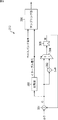
図1は、本技術の一実施の形態に係る通信装置101の構成例を示すブロック図である。通信装置101は、通信アンテナ111、周波数変換部112、ノイズ除去部113、復調部114、XO(X'tal Oscillator;水晶発振器)115、及び、TCXO(Temperature Compensated X'tal Oscillator;温度補償型水晶発振器)116を備える。
<1. Embodiment>
FIG. 1 is a block diagram illustrating a configuration example of a
通信アンテナ111は、GPS衛星から送信されるRF信号(以下、GPS信号とも称する)を受信する。 The communication antenna 111 receives an RF signal (hereinafter also referred to as a GPS signal) transmitted from a GPS satellite.
ここで、GPS信号は、航法メッセージ等の送信データを拡散符号によりスペクトラム拡散し、得られたスペクトラム拡散信号に搬送波を乗算し、BPSK(Binary Phase Shift Keying)変調した信号である。また、スペクトラム拡散に用いる拡散符号には、1023チップのC/Aコードと呼ばれる擬似ランダム雑音符号(PNコード)が用いられ、GPS衛星毎に異なるC/Aコードが割り当てられている。 Here, the GPS signal is a signal obtained by spectrum-spreading transmission data such as a navigation message using a spread code, multiplying the obtained spectrum spread signal by a carrier wave, and modulating the signal by BPSK (Binary Phase Shift Keying). In addition, a pseudo random noise code (PN code) called a 1023 chip C / A code is used as a spread code used for spread spectrum, and a different C / A code is assigned to each GPS satellite.
周波数変換部112は、通信アンテナ111が受信したGPS信号の周波数Frfを、中間周波数Fifにダウンコンバートすることにより、GPS信号をIF信号(中間周波数信号)に変換する。そして、周波数変換部112は、アナログのIF信号に基づいて離散化し、離散化信号を出力する。以下、周波数変換部112の構成例について説明する。 The frequency conversion unit 112 converts the GPS signal into an IF signal (intermediate frequency signal) by down-converting the frequency Frf of the GPS signal received by the communication antenna 111 into the intermediate frequency Fif. Then, the frequency converter 112 discretizes based on the analog IF signal and outputs a discretized signal. Hereinafter, a configuration example of the frequency conversion unit 112 will be described.
[周波数変換部112の構成例]
周波数変換部112は、LNA(ローノイズ・アンプ)121、中間周波数変換部122、増幅器123、BPF(バンドパス・フィルタ)124、及び、A/Dコンバータ125を備える。
[Configuration Example of Frequency Conversion Unit 112]
The frequency converter 112 includes an LNA (low noise amplifier) 121, an intermediate frequency converter 122, an
LNA121は、通信アンテナ111が受信したGPS信号を増幅する。 The LNA 121 amplifies the GPS signal received by the communication antenna 111.
中間周波数変換部122は、LNA121により増幅されたGPS信号の周波数を、デジタル信号処理が施しやすいように、例えば、4.092MHzや1.023MHzなどの搬送波周波数よりも低い中間周波数Fifに変換(ダウンコンバート)する。ここで、中間周波数変換部122の構成例について説明する。
The intermediate frequency converter 122 converts the frequency of the GPS signal amplified by the
〔中間周波数変換部122の構成例〕
中間周波数変換部122は、BPF(バンドパス・フィルタ)131、増幅器132、周波数シンセサイザ133、及び、ミキサ134を備える。
[Configuration Example of Intermediate Frequency Conversion Unit 122]
The intermediate frequency conversion unit 122 includes a BPF (bandpass filter) 131, an
BPF131は、LNA121から出力される増幅されたGPS信号に対して、特定の周波数帯域の信号のみを通過させ、その他の帯域の信号を減衰させる。
The
増幅器132は、BPF131から出力されるGPS信号を増幅する。ここで、増幅器132は、例えば、MOSFET(Metal Oxide Semiconductor Field effect transistor)差動増幅器で構成することができるが、上記に限られない。
The
周波数シンセサイザ133は、TCXO116(後述する)から供給される発振信号に基づいて、所定の周波数を有する局部発振信号を生成する。ここで、周波数シンセサイザ133は、例えば、復調部114が備えるMPU143により制御されるが、上記に限られず、制御部(図示せず)により制御されてもよい。
The
ミキサ134は、増幅器132から出力される増幅されたGPS信号に対して、周波数シンセサイザ133から出力される局部発振信号を乗算する。ミキサ134がGPS信号と局部発振信号とを乗算することによって、局部発振信号に応じて、搬送波周波数よりも低い中間周波数FifにダウンコンバートされたIF信号を出力することができる。
The
中間周波数変換部122は、例えば上記のような構成によって、GPS信号の周波数が中間周波数へダウンコンバートされたIF信号を出力する。 The intermediate frequency converter 122 outputs an IF signal in which the frequency of the GPS signal is down-converted to the intermediate frequency, for example, with the above-described configuration.
増幅器123は、中間周波数変換部122から出力されたIF信号を増幅する。ここで、増幅器123は、例えば、オペアンプで構成することができるが、上記に限られない。
The
BPF124は、増幅器123から出力される増幅されたIF信号に対して、特定の周波数帯域の信号のみを通過させ、その他の帯域の信号を減衰させる。なお、本技術の実施形態に係る通信装置は、BPF124を、遮断周波数より大きな周波数の信号を減衰させるローパス・フィルタ(Low-Pass Filter)で構成することもできる。ここで、LNA121〜BPF124までに処理される信号は、アナログ信号である。
The
A/Dコンバータ125は、BPF124から出力されるアナログのIF信号に基づいて離散化し、離散化信号を出力する。ここで、A/Dコンバータ125は、例えば、Nビットの分解能を有するA/Dコンバータで構成され、定常的な熱雑音の平均振幅をA/Dコンバータ125の下位Mビットに設定する。したがって、A/Dコンバータ125は、外来ノイズによるA/Dコンバータの出力スペクトラムの飽和を防止し、A/Dコンバータ125の後段に備えられるノイズ除去部113において外来ノイズをより確実に除去させることができる。
The A /
周波数変換部112は、例えば上記のような構成によって、通信アンテナ111が受信したGPS信号の周波数Frfを中間周波数FifにダウンコンバートしたIF信号に変換し、デジタル信号としての離散化信号を出力することができる。 The frequency conversion unit 112 converts the frequency Frf of the GPS signal received by the communication antenna 111 into an IF signal down-converted to the intermediate frequency Fif, for example, by the configuration as described above, and outputs a discretized signal as a digital signal. Can do.
ノイズ除去部113は、周波数変換部112から出力される離散化信号に基づいて、離散化信号に対する外来ノイズを検出して外来ノイズを除去する。
The
復調部114は、ノイズ除去部113から出力される離散化信号に基づいてスペクトラム拡散信号を検出し、検出されたスペクトラム拡散信号を復調する。以下、復調部114の構成例について説明する。
[復調部114の構成例]
復調部114は、同期捕捉部141、同期保持部142、MPU143、RTC(Real Time Clock)144、タイマ145、メモリ146、及び、逓倍/分周器147を備える。
[Configuration Example of Demodulator 114]
The
同期捕捉部141は、MPU143の制御の下、逓倍/分周器147から供給される逓倍又は分周された発振信号に基づいて、ノイズ除去部113から出力される離散化信号におけるC/Aコードの同期捕捉を行う。また、同期捕捉部141は、C/Aコードの同期捕捉と共に、ノイズ除去部113から出力される離散化信号における搬送波周波数(キャリア周波数)や、GPS信号の送信元のGPS衛星を示す装置識別情報(例えば、GPS衛星を識別する衛星番号など)を検出する。そして、同期捕捉部141は、検出したC/Aコードの位相、搬送波周波数、装置識別情報を、同期保持部142及びMPU143に供給する。
The
同期保持部142は、MPU143の制御の下、逓倍/分周器147から供給される逓倍又は分周された発振信号と、同期捕捉部141から伝達される各種情報(C/Aコードの位相、搬送波周波数、及び装置識別情報)とに基づいて、ノイズ除去部113から出力される離散化信号におけるC/Aコードと、搬送波(キャリア)との同期保持を行う。また、同期保持部142は、同期保持と共に、ノイズ除去部113から出力される離散化信号に含まれるデータを復調する。ここで、同期保持部142は、同期捕捉部141から伝達されるC/Aコードの位相、搬送波周波数、及び装置識別情報を初期値として処理を開始する。
The
また、同期保持部142は、検出したC/Aコードの位相、搬送波周波数、及び復調したデータを、MPU143に伝達する。なお、同期保持部142は、複数のGPS衛星から送信された送信信号に対応する離散化信号それぞれに対して、同期保持を並列に行うことができる。また、同期保持部142としては、例えば、特開2003−232844号公報に開示された技術を用いることが挙げられるが、上記に限られない。
In addition, the
MPU143は、同期保持部142から伝達されるC/Aコードの位相、搬送波周波数、及びデータに基づいて処理を行う。例えば、MPU143は、通信装置101の位置及び速度を算出し、また、復調されたデータから得られる各GPS衛星の時間情報に基づいて通信装置101の時間情報を補正するというような、GPSに関する各種演算処理を行う。
The
また、MPU143は、通信装置101の各部の制御や、外部装置との入出力に関する制御などを行うこともできる。上記の場合には、MPU143は、通信装置101における制御部(図示せず)として機能することとなる。
Also, the
RTC144は、XO115から供給される発振信号に基づいて時間を計測する。RTC144によって計測される時間情報は、例えば、GPS衛星の時間情報が得られるまでの間に代用されるものであり、GPS衛星の時間情報が得られたときには、MPU143がタイマ145を制御することによって適宜補正される。
The
タイマ145は、例えば、MPU143における通信装置101の各部の動作を制御する各種タイミング信号の生成や、時間の参照に用いられる。
The timer 145 is used, for example, to generate various timing signals that control the operation of each unit of the
メモリ146は、例えば、ROMやRAMで構成される。メモリ146を構成するROMには、MPU143が使用するプログラムや演算パラメータなどの制御用データが記録される。また、RAMには、MPU143により実行されるプログラムなどが一次記憶される。
The
逓倍/分周器147は、TCXO116から供給される発振信号を逓倍(multiply)又は分周(divide)する。
The multiplier /
復調部114は、例えば上記のような構成によって、ノイズ除去部113から伝達される離散化信号に基づいてスペクトラム拡散信号を検出し、復調することができる。
The
XO115は、例えば32.768kHzなどの所定の発振周波数を有する発振信号を生成する。そして、XO115は、生成した発振信号をRTC144に供給する。
The
TCXO116は、例えば18.414MHzなど、XO115が生成する発振信号とは周波数が異なる発振信号を生成する。そして、TCXO116は、生成した発振信号を、逓倍/分周器147や周波数シンセサイザ133などに供給する。
The
[同期捕捉部141の構成例]
図2は、同期捕捉部141の構成例を示すブロック図である。同期捕捉部141は、同期捕捉処理部201及び制御部202を備える。ここで、同期捕捉処理部201の構成例について説明する。
[Configuration Example of Synchronization Acquisition Unit 141]
FIG. 2 is a block diagram illustrating a configuration example of the
〔同期捕捉処理部201の構成例〕
同期捕捉処理部201は、周波数変換部211、フィルタ212、ダウンサンプリング部213、コヒーレント加算部214、PN生成部215、及び、位相検出部216を備える。
[Configuration Example of Synchronization Acquisition Processing Unit 201]
The synchronization acquisition processing unit 201 includes a
周波数変換部211は、ノイズ除去部113から供給される離散化信号の周波数を、中心周波数がほぼ0Hzになるようにダウンコンバートする。具体的には、周波数変換部211は、制御部202の周波数シフト量設定部232により設定される周波数シフト量Fsftだけ離散化信号の周波数をシフトする。周波数変換部211は、周波数を変換した離散化信号(以下、ベースバンド信号と称する)をフィルタ212に供給する。
The
フィルタ212は、例えば、ローパスフィルタにより構成され、ベースバンド信号の所定の周波数以上の高調波成分を除去し、ダウンサンプリング部213に供給する。
The
ダウンサンプリング部213は、制御部202のサンプリング間隔設定部233により設定されるサンプリング間隔Isで、ベースバンド信号のダウンサンプリングを行う。そして、ダウンサンプリング部213は、ダウンサンプリングしたベースバンド信号をコヒーレント加算部214に供給する。
The
コヒーレント加算部214は、ダウンサンプリングされたベースバンド信号のコヒーレント加算を行う。すなわち、コヒーレント加算部214は、ダウンサンプリングされたベースバンド信号を、C/Aコードのチップ長(1023チップ)に対応する1023ビット単位で区切り、複数の区間のデータの値を対応するビット毎に積算する処理を行う。コヒーレント加算部214は、コヒーレント加算の演算結果を示すデータ(以下、コヒーレント加算データと称する)を相関演算部221に供給する。
The
PN生成部215は、各GPS衛星のC/Aコードを生成し、生成したC/Aコードの位相をシフトさせながら相関演算部221に供給する。
The
位相検出部216は、ベースバンド信号におけるC/Aコードの位相を検出する。位相検出部216は、相関演算部221及びピーク検出部222により構成される。
The
相関演算部221は、コヒーレント加算部214から供給されるコヒーレント加算データと、PN生成部から供給されるC/Aコードとの相関演算を行い、得られた相関値をピーク検出部222に供給する。
The
ピーク検出部222は、相関値のピークを検出することにより、C/Aコードの種類及び位相を検出する。すなわち、ピーク検出部222は、相関演算部221から供給される相関値が所定の閾値以上となるピークを検出し、そのときのC/Aコードの種類及び位相を検出する。また、ピーク検出部222は、検出したC/Aコードの種類から同期捕捉を行ったGPS信号の送信元のGPS衛星を検出する。そして、ピーク検出部222は、検出したC/Aコードの位相、及び、検出したGPS衛星を示す装置識別情報を、同期保持部142及びMPU143に供給する。
The
制御部202は、同期捕捉処理部201の各部の処理を制御する。例えば、制御部202は、例えば、MPU143により構成することも可能であるし、MPU143とは別に構成することも可能である。ここで、制御部202の構成例について説明する。
The control unit 202 controls processing of each unit of the synchronization acquisition processing unit 201. For example, the control unit 202 can be configured by the
〔制御部202の構成例〕
制御部202は、少なくともドップラシフト量算出部231、周波数シフト量設定部232、及び、サンプリング間隔設定部233を備える。
[Configuration Example of Control Unit 202]
The control unit 202 includes at least a Doppler shift
ドップラシフト量算出部231は、同期捕捉の対象となるGPS衛星からのGPS信号のドップラシフト量を算出する。より具体的には、ドップラシフト量算出部231は、当該GPS衛星からのエフェメリスデータに基づいて、同期捕捉開始時の通信装置101の位置及び時刻におけるGPS信号のドップラシフト量及び単位時間あたりのドップラシフト量の変化量を算出する。そして、ドップラシフト量算出部231は、算出したドップラシフト量及び単位時間あたりのドップラシフト量の変化量を、周波数シフト量設定部232及びサンプリング間隔設定部233に供給する。
The Doppler shift
なお、以下、ドップラシフト量算出部231により算出される同期捕捉開始時のドップラシフト量を、初期ドップラシフト量Fds0と称し、単位時間あたりのドップラシフト量の変化量を、ドップラシフト変化量ΔFdsと称する。
Hereinafter, the Doppler shift amount at the start of synchronization acquisition calculated by the Doppler shift
周波数シフト量設定部232は、所定のタイミングで、初期ドップラシフト量Fds0、ドップラシフト変化量ΔFds、中間周波数Fif、A/Dコンバータ125のサンプリング周波数Fsmp等を周波数変換部211に供給する。これにより、後述するように、周波数変換部211の周波数シフト量Fsftが設定される。
The frequency shift
サンプリング間隔設定部233は、初期ドップラシフト量Fds0に基づいて、サンプリング間隔Isを設定するためのカウント幅ΔCを算出する。そして、サンプリング間隔設定部233は、算出したカウント幅ΔC、及び、標準サンプリング間隔Is0をダウンサンプリング部213に供給する。これにより、ダウンサンプリング部213のサンプリング間隔Isが設定される。
The sampling
ここで、標準サンプリング間隔Is0とは、ドップラシフトが発生していない場合のダウンサンプリング部213のサンプリング間隔のことである。例えば、A/Dコンバータ125のサンプリング周波数Fsmpが16.368ギガサンプル/秒である場合、標準サンプリング間隔Is0は、16ビットに設定される。従って、この場合、標準サンプリング間隔Is0でダウンサンプリングが行われたとき、ベースバンド信号は1023メガサンプル/秒にダウンサンプリングされる。
Here, the standard sampling interval Is0 is a sampling interval of the
[周波数変換部211の構成例]
図3は、周波数変換部211の構成例を示すブロック図である。周波数変換部211は、NCO(Numerical Controlled Oscillator)251及び複素乗算部252を備える。ここで、NCO251の構成例について説明する。
[Configuration Example of Frequency Conversion Unit 211]
FIG. 3 is a block diagram illustrating a configuration example of the
〔NCO251の構成例〕
NCO251は、積分器261、加算部262、除算部263、乗算部264、位相アキュムレータ265、cos波生成部266、及び、sin波生成部267を備える。
[Configuration example of NCO 251]
The NCO 251 includes an
積分器261は、周波数シフト量設定部232からドップラシフト変化量ΔFdsが供給される毎に、ドップラシフト変化量ΔFdsを積算する。そして、積分器261は、積算値を加算部262に供給する。従って、積分器261からは、n×ΔFds(n=0、1、2、3・・・)が出力される。
The
加算部262は、周波数シフト量設定部232から供給される中間周波数Fif、初期ドップラシフト量Fds0、及び、積分器261から供給される積分値を加算し、得られた加算値を除算部263に供給する。この加算値が、上述した周波数シフト量Fsftとなる。従って、周波数シフト量Fsftは、Fif+Fds0+n×ΔFds(n=0、1、2、3・・・)となる。
The adding
除算部263は、加算部262から供給される周波数シフト量Fsftを、周波数シフト量設定部232から供給されるサンプリング周波数Fsmpで割り、得られた除算値を乗算部264に供給する。従って、除算部263からは、Fsft/Fsmpが出力される。
The
乗算部264は、除算部263から供給される除算値に、周波数シフト量設定部232から供給される定数である2πを乗じ、得られた乗算値を位相アキュムレータ265に供給する。なお、以下、この乗算値を位相幅Δθと称する。従って、位相幅Δθは、2π×Fsft/Fsmpとなる。この位相幅Δθは、cos波生成部266から出力されるcos波、及び、sin波生成部267から出力されるsin波の各サンプル間の位相差となる。
The
位相アキュムレータ265は、cos波生成部266及びsin波生成部267からサンプル値が出力される毎に位相幅Δθを積算し、その積算値である位相θを、cos波生成部266及びsin波生成部267に供給する。従って、位相θは、1サンプル毎に0、Δθ、2Δθ、3Δθ・・・のように増加する。
The
cos波生成部266は、位相アキュムレータ265から供給される位相θに対応する余弦値cosθを出力する。従って、cos波生成部266からは、周波数が周波数シフト量Fsft(=Fif+Fds0+n×ΔFds)と一致するcos波の離散化信号I1が出力される。
The cos wave
sin波生成部267は、位相アキュムレータ265から供給される位相θに対応する正弦値sinθを出力する。従って、sin波生成部267からは、周波数が周波数シフト量Fsft(=Fif+Fds0+n×ΔFds)と一致するsin波の離散化信号Q1が出力される。
The
複素乗算部252は、ノイズ除去部113から供給される離散化信号と、NCO251から供給される離散化信号の複素乗算を行う。具体的には、ノイズ除去部113から供給される離散化信号のQ成分をQ0とし、I成分をI0とした場合、複素乗算部252は、I0×I1+Q0×Q1を算出し、算出値をI成分として出力し、I0×Q1+I1×Q0を算出し、算出値をQ成分として出力する。これにより、複素乗算部252からは、離散化信号の周波数を周波数シフト量Fsftだけシフトしたベースバンド信号が出力される。
The
[ダウンサンプリング部213の構成例]
図4は、ダウンサンプリング部213の構成例を示すブロック図である。ダウンサンプリング部213は、加算部301、減算部302、セレクタ304、バッファ305、及び、比較器303を備える。
[Configuration Example of Downsampling Unit 213]
FIG. 4 is a block diagram illustrating a configuration example of the
加算部301は、バッファ305のバッファ値Bに、サンプリング間隔設定部233から供給されるカウント幅ΔCを加算し、得られたカウント値Cを減算部302、比較器303、及び、セレクタ304に供給する。
The adding
減算部302は、サンプリング間隔設定部233から供給される標準サンプリング間隔Is0をカウント値Cから引き、得られた減算値C−Is0をセレクタ304に供給する。
The
比較器303は、カウント値Cと標準サンプリング間隔Is0を比較する。そして、比較器303は、カウント値Cが標準サンプリング間隔Is0以上の場合、イネーブル信号の値を1(Highレベル)に設定し、カウント値Cが標準サンプリング間隔Is0未満の場合、イネーブル信号の値を0(Lowレベル)に設定する。
The
セレクタ304は、比較器303から出力されるイネーブル信号が0の場合、加算部301から供給されるカウント値Cをバッファ305に供給し、イネーブル信号が1の場合、減算部302から供給される減算値C−Is0をバッファ305に供給する。
The
バッファ305は、セレクタ304から供給される値の最新値を保持するとともに、保持しているバッファ値Bを加算部301に供給する。
The
サンプリング部306は、イネーブル信号が0のとき値を出力せず、イネーブル信号が1になったときのベースバンド信号の値を出力する。これにより、ベースバンド信号の値が間引きされる。すなわち、ベースバンド信号がダウンサンプリングされる。
The
[同期捕捉処理の詳細]
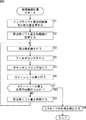
次に、図5のフローチャートを参照して、同期捕捉部141により実行される同期捕捉処理の詳細について説明する。
[Details of synchronization acquisition processing]
Next, details of the synchronization acquisition process executed by the
ステップS1において、ドップラシフト量算出部231は、ドップラシフト量の初期値及び変化量を求める。ここで、図6乃至図8を参照して、ドップラシフト量の時系列の推移について簡単に説明する。
In step S1, the Doppler shift
図6に模式的に示すように、GPS衛星401は準同期軌道をとっており、通信装置101から見て常に動いているように見える。また、図7に示すように、通信装置101に対するGPS衛星401の移動速度(相対速度)のうち、通信装置101とGPS衛星401を結ぶ視線方向の速度がドップラシフト量に影響する。
As schematically shown in FIG. 6, the
図8は、ドップラシフト量の時系列の推移の例を示している。図8の横軸は、通信装置101の存在する位置においてGPS衛星401が見え始める時刻からの経過時間(単位は秒)を示し、縦軸は、ドップラシフト量(単位はHz)を示している。
FIG. 8 shows an example of time-series transition of the Doppler shift amount. The horizontal axis in FIG. 8 indicates the elapsed time (in seconds) from the time when the
上述したように、GPS衛星401は、通信装置101から見て常に動いているため、図8に示されるように、ドップラシフト量は時々刻々と変化する。また、ドップラシフト量は、GPS衛星401が日の出位置付近にいるときに最大となる。ここで、日の出位置とは、通信装置101の存在する位置からGPS衛星401が見え始める位置である。すなわち、日の出位置付近においては、GPS衛星401の視線方向の速度が、通信装置101に近づく方向に最大となるため、ドップラシフト量は周波数が増大する方向(正の方向)に最大となる。従って、GPS衛星401が日の出位置付近にいるとき、通信装置101が受信するGPS信号の見かけの周波数が最大となる。
As described above, since the
一方、ドップラシフト量は、GPS衛星401が日の入り位置付近にいるときに最小となる。ここで、日の入り位置とは、通信装置101の存在する場所からGPS衛星401が見えなくなる直前の位置である。すなわち、日の入り位置付近においては、GPS衛星401の視線方向の速度が、通信装置101から遠ざかる方向に最大となるため、ドップラシフト量は周波数が減少する方向(負の方向)に最大となる。従って、GPS衛星401が日の入り位置付近にいるとき、通信装置101が受信するGPS信号の見かけの周波数が最小となる。
On the other hand, the Doppler shift amount is minimized when the
また、ドップラシフト量は、GPS衛星401が天頂付近にいるときに、ほぼ0となる。すなわち、天頂付近においては、GPS衛星401の視線方向の速度が、ほぼ0となるため、ドップラシフト量もほぼ0となる。
Further, the Doppler shift amount becomes almost zero when the
ここで、図8に示されるGPS衛星401からのGPS信号のドップラシフト量の推移は、GPS衛星401から送信されるエフェメリスデータに基づいて算出することが可能である。
Here, the transition of the Doppler shift amount of the GPS signal from the
そこで、ドップラシフト量算出部231は、同期捕捉を行う対象となるGPS衛星からのエフェメリスデータに基づいて、同期捕捉開始時の位置及び時刻における当該GPS衛星からのGPS信号のドップラシフト量を、初期ドップラシフト量Fds0として求める。また、ドップラシフト量算出部231は、同期捕捉開始時の位置及び時刻におけるドップラシフト量の単位時間(例えば、1ミリ秒)あたりの変化量を、ドップラシフト変化量ΔFdsとして求める。ドップラシフト変化量ΔFdsは、例えば、図8のドップラシフト量の推移を示すグラフの傾きにより表される。
Therefore, the Doppler shift
また、ドップラシフト量算出部231は、算出した初期ドップラシフト量Fds0及びドップラシフト変化量ΔFdsを、周波数シフト量設定部232及びサンプリング間隔設定部233に供給する。
Also, the Doppler shift
ステップS2において、周波数シフト量設定部232は、周波数シフト量Fsftを初期値に設定する。具体的には、周波数シフト量設定部232は、中間周波数Fif及び初期ドップラシフト量Fds0を周波数変換部211の加算部262に供給する。これにより、周波数シフト量Fsftが、Fif+Fds0に設定される。また、周波数シフト量設定部232は、A/Dコンバータ125のサンプリング周波数Fsmpを周波数変換部211の除算部263に供給し、定数2πを周波数変換部211の乗算部264に供給する。
In step S2, the frequency shift
ステップS3において、周波数変換部211は、周波数変換を行う。すなわち、周波数変換部211は、図3を参照して上述した処理により、ノイズ除去部113から供給される離散化信号の周波数を周波数シフト量Fsft(=Fif+Fds)だけシフトする。また、周波数変換部211は、周波数をシフトすることにより得られるベースバンド信号をフィルタ212に供給する。
In step S3, the
これにより、ベースバンド信号の周波数は、元の離散化信号の周波数から、中間周波数Fifと初期ドップラシフト量Fds0を合わせた周波数だけシフトした周波数となる。すなわち、周波数変換部211では、中間周波数Fif分の周波数シフトに加えて、ドップラシフトの補正が行われる。従って、このベースバンド信号は、ドップラシフト量の大きさに関わらず、スペクトラム拡散信号をBPSK変調した信号であって、中心周波数がほぼ0Hzの信号となる。
As a result, the frequency of the baseband signal is a frequency that is shifted from the original frequency of the discretization signal by a frequency obtained by adding the intermediate frequency Fif and the initial Doppler shift amount Fds0. That is, the
ステップS4において、フィルタ212は、フィルタリングを行う。すなわち、フィルタ212は、所定の周波数以上の高調波成分をベースバンド信号から除去し、高調波成分を除去したベースバンド信号をダウンサンプリング部213に供給する。
In step S4, the
ステップS5において、同期捕捉部141は、ダウンサンプリングを行う。このダウンサンプリングの処理では、以下に述べる理由により、初期ドップラシフト量Fds0に基づいてサンプリング間隔Isが調整される。
In step S5, the
具体的には、ドップラシフトによりGPS信号の見かけの周波数が変化すると、図9に示されるように、GPS信号に含まれるメッセージの見かけの時間軸上の長さが変化する。すなわち、ドップラシフトによりGPS信号の見かけの周波数が高くなると、GPS信号に含まれるメッセージの見かけの時間が短くなる。一方、A/Dコンバータ125のサンプリング周波数Fsmpは一定なので、メッセージに割り当てられるビット数が減少し、メッセージ長が短くなる。
Specifically, when the apparent frequency of the GPS signal changes due to the Doppler shift, the apparent length of the message included in the GPS signal changes as shown in FIG. That is, when the apparent frequency of the GPS signal is increased by Doppler shift, the apparent time of the message included in the GPS signal is shortened. On the other hand, since the sampling frequency Fsmp of the A /
逆に、ドップラシフトによりGPS信号の見かけの周波数が低くなると、GPS信号に含まれるメッセージの見かけの時間が長くなる。一方、A/Dコンバータ125のサンプリング周波数Fsmpは一定なので、メッセージに割り当てられるビット数が増加し、メッセージ長が長くなる。
Conversely, when the apparent frequency of the GPS signal is lowered due to the Doppler shift, the apparent time of the message included in the GPS signal becomes longer. On the other hand, since the sampling frequency Fsmp of the A /
このように、ドップラシフトによりメッセージ長が変化するにも関わらず、常にサンプリング間隔を一定にしたのでは、ベースバンド信号を適切にダウンサンプリングすることができない。 As described above, the baseband signal cannot be down-sampled appropriately if the sampling interval is always constant, even though the message length changes due to the Doppler shift.
具体的には、図10は、ドップラシフトが発生している場合と発生していない場合とで、同じメッセージを同じサンプリング間隔でダウンサンプリングした例を示している。図の上側が、ドップラシフト量が0Hz、すなわち、ドップラシフトが発生していない場合を示している。また、図の下側が、ドップラシフト量がFdsHz(>0Hz)、すなわち、周波数が高くなる方向にドップラシフトが発生している場合を示している。 Specifically, FIG. 10 shows an example in which the same message is down-sampled at the same sampling interval when the Doppler shift occurs and when it does not occur. The upper side of the figure shows a case where the Doppler shift amount is 0 Hz, that is, no Doppler shift occurs. Further, the lower side of the figure shows a case where the Doppler shift amount is FdsHz (> 0 Hz), that is, the Doppler shift is generated in the direction of increasing the frequency.
ダウンサンプリング部213では、比較器303からのイネーブル信号がHighになるタイミングで、ベースバンド信号のサンプリングが行われる。そして、図10に示されるように、ドップラシフトが発生している場合、ドップラシフトが発生していない場合と比較して、同じメッセージに対してサンプリングする回数が少なくなる。すなわち、ドップラシフトが発生していない場合と比較して、ダウンサンプリング後のメッセージに情報の漏れが生じ、メッセージ長が短くなる。
The
一方、図示は省略するが、ドップラシフト量がFdsHz(<0Hz)、すなわち、周波数が低くなる方向にドップラシフトが発生した場合、ドップラシフトが発生していない場合と比較して、同じメッセージに対してサンプリングする回数が多くなる。すなわち、ドップラシフトが発生していない場合と比較して、ダウンサンプリング後のメッセージに情報の冗長化が発生し、メッセージ長が長くなる。 On the other hand, although not shown, when the Doppler shift amount is FdsHz (<0 Hz), that is, when the Doppler shift occurs in the direction of decreasing frequency, the same message is compared with the case where the Doppler shift does not occur. The number of times of sampling increases. That is, as compared with a case where no Doppler shift occurs, information redundancy occurs in the message after downsampling, and the message length becomes longer.
このように、ドップラシフトの影響により、ダウンサンプリング後のベースバンド信号に含まれるメッセージ長が変動する。当然、ベースバンド信号に含まれるC/Aコードも同様に、ドップラシフトの影響により値の漏れや冗長化が発生し、長さが変動する。そして、後述する相関演算のピークが発生しにくくなり、同期捕捉の精度が低下する。 Thus, the message length included in the baseband signal after downsampling varies due to the influence of the Doppler shift. Naturally, the length of the C / A code included in the baseband signal also fluctuates due to the influence of the Doppler shift, and the length varies. Then, the peak of correlation calculation described later hardly occurs, and the accuracy of synchronization acquisition decreases.
そこで、まず、サンプリング間隔設定部233は、次式(1)により、カウント幅ΔCを算出する。
Therefore, first, the sampling
ΔC=(Frf+Fds0)/Frf ・・・(1) ΔC = (Frf + Fds0) / Frf (1)
式(1)から、初期ドップラシフト量Fds0が0Hzの場合、カウント幅ΔCは1に設定される。一方、初期ドップラシフト量Fds0>0Hzであり、GPS信号の見かけの周波数が高くなっている場合、カウント幅ΔCは1より大きな値に設定される。また、初期ドップラシフト量Fds0<0Hzであり、GPS信号の見かけの周波数が低くなっている場合、カウント幅ΔCは1より小さな値に設定される。 From equation (1), when the initial Doppler shift amount Fds0 is 0 Hz, the count width ΔC is set to 1. On the other hand, when the initial Doppler shift amount Fds0> 0 Hz and the apparent frequency of the GPS signal is high, the count width ΔC is set to a value larger than 1. Further, when the initial Doppler shift amount Fds0 <0 Hz and the apparent frequency of the GPS signal is low, the count width ΔC is set to a value smaller than 1.
そして、サンプリング間隔設定部233は、カウント幅ΔCをダウンサンプリング部213の加算部301に供給し、標準サンプリング間隔Is0をダウンサンプリング部213の減算部302に供給する。
Then, the sampling
加算部301は、A/Dコンバータ125のサンプリング周期と同期して、バッファ305のバッファ値Bとカウント幅ΔCを加算したカウント値Cを、減算部302、比較器303、及び、セレクタ304に供給する。
The
減算部302は、カウント値Cから標準サンプリング間隔Is0を引き、得られた減算値C−Is0をセレクタ304に供給する。
The
比較器303は、カウント値Cが標準サンプリング間隔Is0未満の場合、イネーブル信号の値を0に設定し、カウント値Cが標準サンプリング間隔Is0以上の場合、イネーブル信号の値を1に設定する。
The
セレクタ304は、イネーブル信号の値が0の場合、カウント値Cをバッファ305に供給し、バッファ305に保持させる。一方、セレクタ304は、イネーブル信号の値が1の場合、減算値C−Is0をバッファ305に供給し、バッファ305に保持させる。
When the value of the enable signal is 0, the
サンプリング部306は、イネーブル信号が0のとき値を出力せず、イネーブル信号が1になったときのベースバンド信号の値を出力する。
The
このようにして、ベースバンド信号のダウンサンプリングが行われる。 In this way, the baseband signal is down-sampled.
ここで、標準サンプリング間隔Is0=16ビットとした場合のドップラシフト量と実際のサンプリング間隔Isの関係を、図11乃至図13を参照して説明する。 Here, the relationship between the Doppler shift amount and the actual sampling interval Is when the standard sampling interval Is0 = 16 bits will be described with reference to FIGS.
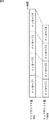
例えば、ドップラシフトが発生しておらず、カウント幅ΔCが1に設定されている場合、図11に示されるように、バッファ値Bが0にリセットされた後、ベースバンド信号が1ビット(1サンプル)進む毎に、バッファ値B及びカウント値Cが1ずつ増えていく。その後、ベースバンド信号が16ビット目まで進んだ時点で、バッファ値Bが15になる。そして、ベースバンド信号の17ビット目で、カウント値Cが16になり、イネーブル信号の値が1に設定される。これにより、ベースバンド信号の17ビット目の値がサンプリングされる。 For example, when the Doppler shift has not occurred and the count width ΔC is set to 1, as shown in FIG. 11, the buffer value B is reset to 0 and then the baseband signal is 1 bit (1 As the sample progresses, the buffer value B and the count value C increase by one. Thereafter, when the baseband signal advances to the 16th bit, the buffer value B becomes 15. Then, at the 17th bit of the baseband signal, the count value C becomes 16, and the value of the enable signal is set to 1. As a result, the value of the 17th bit of the baseband signal is sampled.
その後、カウント値Cから16(=標準サンプリング間隔Is0)を引いた値、すなわち0がバッファ305に供給され、バッファ値Bが0にリセットされる。以降、同様のループ処理が繰り返され、ベースバンド信号が、標準サンプリング間隔Is0と同じ16ビット間隔でサンプリングされる。従って、ダウンサンプリング後のベースバンド信号のサンプリング周波数は、Fsmp/Is0(=Fsmp/16)となる。
Thereafter, a value obtained by subtracting 16 (= standard sampling interval Is0) from the count value C, that is, 0 is supplied to the
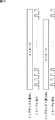
一方、初期ドップラシフト量Fds0>0であり、カウント幅ΔCが1より大きい値に設定されている場合、図12に示されるように、バッファ値Bが0にリセットされた後、ベースバンド信号が1ビット(1サンプル)進む毎に、バッファ値B及びカウント値CがΔCずつ増えていく。その後、ベースバンド信号が16ビット目まで進んだ時点で、バッファ値Bが15を超える。そして、ベースバンド信号の17ビット目で、カウント値Cが16を超え、イネーブル信号の値が1に設定される。これにより、ベースバンド信号の17ビット目の値がサンプリングされる。 On the other hand, when the initial Doppler shift amount Fds0> 0 and the count width ΔC is set to a value larger than 1, the baseband signal is reset after the buffer value B is reset to 0 as shown in FIG. The buffer value B and the count value C increase by ΔC every time one bit (one sample) is advanced. Thereafter, when the baseband signal advances to the 16th bit, the buffer value B exceeds 15. Then, at the 17th bit of the baseband signal, the count value C exceeds 16, and the value of the enable signal is set to 1. As a result, the value of the 17th bit of the baseband signal is sampled.
その後、カウント値Cから16(=標準サンプリング間隔Is0)を引いた余りRがバッファ305に供給され、次のループ処理に持ち越される。すなわち、次のループ処理では、余りRからカウントが開始される。従って、ベースバンド信号のサンプリングが行われる毎に、ループ処理のバッファ値Bの初期値が増えていき、サンプリング間隔が15ビットに短縮される場合が発生する。その結果、サンプリング間隔Isの平均値は、16ビットより短くなる。
Thereafter, the remainder R obtained by subtracting 16 (= standard sampling interval Is0) from the count value C is supplied to the
図13は、初期ドップラシフト量Fds0=0の場合と、初期ドップラシフト量Fds0>0の場合のイネーブル信号の出力間隔を比較した模式図である。上述したように、初期ドップラシフト量Fds0>0の場合、イネーブル信号の出力間隔が短くなり、その結果、サンプリング間隔Isが短くなる。 FIG. 13 is a schematic diagram comparing the output intervals of the enable signals when the initial Doppler shift amount Fds0 = 0 and when the initial Doppler shift amount Fds0> 0. As described above, when the initial Doppler shift amount Fds0> 0, the output interval of the enable signal is shortened, and as a result, the sampling interval Is is shortened.
逆に、図示は省略するが、初期ドップラシフト量Fds0<0の場合、イネーブル信号の出力間隔が長くなり、その結果、サンプリング間隔Isが長くなる。 On the other hand, although not shown, when the initial Doppler shift amount Fds0 <0, the output interval of the enable signal becomes longer, and as a result, the sampling interval Is becomes longer.
そして、最終的にサンプリング間隔Isの平均値は、Is0/ΔC(=16/ΔC)となる。すなわち、サンプリング間隔Isの平均値は、ドップラシフトが発生していない場合の標準サンプリング間隔Is0の1/ΔC(=Frf/(Frf+Fds0))倍となる。また、ダウンサンプリング後のベースバンド信号のサンプリング周波数は、(Fsmp/Is0)×ΔC(=(Fsmp/16)×ΔC)となる。すなわち、ダウンサンプリング後のベースバンド信号のサンプリング周波数は、ドップラシフトが発生していない場合のΔC倍となる。 Finally, the average value of the sampling interval Is is Is0 / ΔC (= 16 / ΔC). That is, the average value of the sampling interval Is is 1 / ΔC (= Frf / (Frf + Fds0)) times the standard sampling interval Is0 when no Doppler shift occurs. The sampling frequency of the baseband signal after downsampling is (Fsmp / Is0) × ΔC (= (Fsmp / 16) × ΔC). That is, the sampling frequency of the baseband signal after downsampling is ΔC times that when no Doppler shift occurs.
このように、初期ドップラシフト量Fds0に応じて、サンプリング間隔Isが調整されるため、ダウンサンプリング後のベースバンド信号に含まれるC/Aコードの情報の漏れや冗長化の発生が防止される。 In this way, since the sampling interval Is is adjusted according to the initial Doppler shift amount Fds0, leakage of C / A code information contained in the baseband signal after downsampling and occurrence of redundancy are prevented.
図5に戻り、ステップS6において、コヒーレント加算部214は、コヒーレント加算を行う。具体的には、コヒーレント加算部214は、ダウンサンプリング後のベースバンド信号を1023ビット単位でコヒーレント加算する。すなわち、コヒーレント加算部214は、最初のステップS6の処理において、ダウンサンプリング部213から供給される1023ビットのベースバンド信号のデータをそのまま保持する。そして、コヒーレント加算部214は、2回目以降のステップS6の処理において、保持している1023ビットのデータに、ダウンサンプリング後のベースバンド信号の次の1023ビットのデータを対応するビット毎に加算する。これにより、後述する相関演算のピークの検出感度が上昇する。
Returning to FIG. 5, in step S6, the
ステップS7において、制御部202は、コヒーレント加算を所定の回数行ったか否かを判定する。まだコヒーレント加算を所定の回数行なっていないと判定された場合、処理はステップS8に進む。 In step S7, the control unit 202 determines whether or not the coherent addition has been performed a predetermined number of times. If it is determined that the coherent addition has not been performed a predetermined number of times, the process proceeds to step S8.
ステップS8において、周波数シフト量設定部232は、周波数シフト量Fsftを更新する。具体的には、周波数シフト量設定部232は、中間周波数Fif及び初期ドップラシフト量Fds0を周波数変換部211の加算部262に供給し、ドップラシフト変動量ΔFdsを周波数変換部211の積分器261に供給する。
In step S8, the frequency shift
これにより、1回目のステップS8の処理において、周波数シフト量Fsftは、Fif+Fds0+ΔFdsに設定される。以降、同様に、n回目のステップS8の処理において、周波数シフト量Fsftは、Fif+Fds0+n×ΔFdsに設定される。 Thus, in the first process of step S8, the frequency shift amount Fsft is set to Fif + Fds0 + ΔFds. Thereafter, similarly, in the n-th process of step S8, the frequency shift amount Fsft is set to Fif + Fds0 + n × ΔFds.
その後、処理はステップS3に戻り、ステップS7において、コヒーレント加算を所定の回数行ったと判定されるまで、ステップS3乃至S8の処理が繰り返し実行される。すなわち、周波数シフト量Fsftを更新しながら、離散化信号の周波数変換、周波数変換後のベースバンド信号のダウンサンプリング、及び、ダウンサンプリング後のベースバンド信号のコヒーレント加算が繰り返される。 Thereafter, the process returns to step S3, and the processes of steps S3 to S8 are repeatedly executed until it is determined in step S7 that the coherent addition has been performed a predetermined number of times. That is, while updating the frequency shift amount Fsft, the frequency conversion of the discretized signal, the downsampling of the baseband signal after the frequency conversion, and the coherent addition of the baseband signal after the downsampling are repeated.
また、周波数シフト量Fsftは、コヒーレント加算が行われる毎に、ドップラシフト変化量ΔFdsずつ増えるように更新される。換言すれば、初期ドップラシフト量Fds0及びドップラシフト変動量ΔFdsに基づいて、同期捕捉処理の実行中のGPS衛星の動きに対するドップラシフト量の変化が予測され、その変化に追従するように、周波数シフト量Fsftが調整される。従って、同期捕捉開始時に、ドップラシフト量を固定する場合と比較して、より正確に離散化信号のドップラシフトの補正を実行することができる。 Further, the frequency shift amount Fsft is updated so as to increase by the Doppler shift change amount ΔFds every time coherent addition is performed. In other words, based on the initial Doppler shift amount Fds0 and the Doppler shift fluctuation amount ΔFds, a change in the Doppler shift amount with respect to the movement of the GPS satellite during the execution of the synchronization acquisition process is predicted, and the frequency shift is performed so as to follow the change. The amount Fsft is adjusted. Accordingly, the Doppler shift correction of the discretization signal can be performed more accurately than when the Doppler shift amount is fixed at the start of synchronization acquisition.
一方、ステップS7において、コヒーレント加算を所定の回数行ったと判定された場合、処理はステップS9に進む。 On the other hand, if it is determined in step S7 that the coherent addition has been performed a predetermined number of times, the process proceeds to step S9.
ステップS9において、位相検出部216は、C/Aコードの位相を検出する。具体的には、コヒーレント加算部214は、コヒーレント加算により得られたコヒーレント加算データを相関演算部221に供給する。
In step S9, the
PN生成部215は、同期捕捉を行う対象となるGPS衛星のC/Aコードを生成し、生成したC/Aコードの位相を1チップ単位でシフトさせながら、各位相のC/Aコードを相関演算部221に供給する。
The
相関演算部221は、コヒーレント加算データと、各位相のC/Aコードとの相関演算をそれぞれ行い、得られた相関値をピーク検出部222に供給する。
The
ピーク検出部222は、相関値が所定の閾値以上となるピークを検出した場合、そのときのC/Aコードの種類及び位相を検出する。また、ピーク検出部222は、検出したC/Aコードの種類から同期捕捉したGPS信号の送信元のGPS衛星を検出する。そして、ピーク検出部222は、検出したC/Aコードの位相、及び、検出したGPS衛星を示す装置識別情報を、同期保持部142及びMPU143に供給する。
When detecting a peak whose correlation value is equal to or greater than a predetermined threshold, the
一方、ピーク検出部222は、相関値が所定の閾値以上となるピークを検出しなかった場合、受信したGPS信号が同期捕捉の対象としているGPS衛星からのものでないと判定する。
On the other hand, if the
その後、同期捕捉処理は、終了する。なお、必要に応じて、他のGPS衛星を対象として、同期捕捉処理が継続される。 Thereafter, the synchronization acquisition process ends. Note that the synchronization acquisition process is continued for other GPS satellites as necessary.
以上のように、同期捕捉中のドップラシフト量の変化を予測し、その変化に追従して、ドップラシフトの補正量を調整するようにしたので、相関値のピークの検出精度が向上し、その結果、同期捕捉の精度が向上する。 As described above, since the change of the Doppler shift amount during the synchronization acquisition is predicted and the Doppler shift correction amount is adjusted following the change, the detection accuracy of the correlation value peak is improved. As a result, the accuracy of synchronization acquisition is improved.
図14は、同期捕捉中のドップラシフト量の変化の予測機能をオンに設定した場合と、オフに設定した場合の相関演算部221による相関値のピーク値(相関ピーク値)を比較したグラフである。横軸は、コヒーレント加算の回数を示し、縦軸は、相関ピーク値を示している。
FIG. 14 is a graph comparing the peak value (correlation peak value) of the correlation value by the
この図に示されるように、予測機能をオンにした方が、オフにした場合と比較して、相関ピーク値が大きくなっている。従って、予測機能をオンにした方が、より正確にGPS信号のC/Aコードの位相を検出することができる。或いは、予測機能をオンにした方が、より少ないコヒーレント加算回数で、GPS信号のC/Aコードの位相を検出することができ、同期捕捉の所要時間を短縮することができる。 As shown in this figure, the correlation peak value is larger when the prediction function is turned on than when the prediction function is turned off. Therefore, the C / A code phase of the GPS signal can be detected more accurately when the prediction function is turned on. Alternatively, when the prediction function is turned on, the phase of the C / A code of the GPS signal can be detected with a smaller number of coherent additions, and the time required for synchronization acquisition can be shortened.
また、初期ドップラシフト量Fds0に応じて、ダウンサンプリングのサンプリング周期Isを調整するようにしたので、相関値のピークの検出精度が向上し、その結果、同期捕捉の精度が向上する。或いは、より少ないコヒーレント加算回数で、GPS信号のC/Aコードの位相を検出することができ、同期捕捉の所要時間を短縮することができる。 In addition, since the downsampling sampling period Is is adjusted according to the initial Doppler shift amount Fds0, the correlation value peak detection accuracy is improved, and as a result, the synchronization acquisition accuracy is improved. Alternatively, the phase of the C / A code of the GPS signal can be detected with a smaller number of coherent additions, and the time required for synchronization acquisition can be shortened.
さらに、周波数シフト量Fsft及びダウンサンプリングのサンプリング間隔Isの設定には、複雑な演算や処理を行う必要がない。従って、通信装置101の構成や処理を複雑化することなく、同期捕捉の精度を向上させることができる。
Furthermore, setting of the frequency shift amount Fsft and the sampling interval Is for downsampling does not require complicated calculations or processing. Therefore, the accuracy of synchronization acquisition can be improved without complicating the configuration and processing of the
<2.変形例>
以下、上述した本技術の実施の形態の変形例について説明する。
<2. Modification>
Hereinafter, modifications of the above-described embodiment of the present technology will be described.
例えば、中間周波数変換部122を省略して、GPS信号を中間周波数に変換せずに、搬送波周波数のまま処理するようにすることも可能である。 For example, the intermediate frequency conversion unit 122 may be omitted, and the GPS signal may be processed as the carrier frequency without being converted into the intermediate frequency.
また、例えば、コヒーレント加算部214を省略して、ダウンサンプリングを行わずに、ベースバンド信号のコヒーレント加算を行うようにすることも可能である。
Further, for example, the
さらに、例えば、同期捕捉部141の周波数変換部211を、A/Dコンバータ125の前に配置するようにしてもよい。すなわち、A/D変換する前のアナログ信号に対して、周波数シフト量設定部232により設定された周波数シフト量Fsftを用いて、ドップラシフトの補正を行うようにしてもよい。
Further, for example, the
また、例えば、初期ドップラシフト量Fds0とドップラシフト変動量ΔFdsに基づいて、ドップラシフト量の変化を予測する代わりに、周波数シフト量Fsftを更新するタイミングで、エフェメリスデータや、通信装置101の位置及び現在時刻等に基づいて、その都度最新のドップラシフト量を算出するようにしてもよい。
Further, for example, instead of predicting the change of the Doppler shift amount based on the initial Doppler shift amount Fds0 and the Doppler shift fluctuation amount ΔFds, the ephemeris data, the position of the
さらに、以上の説明では、コヒーレント加算を1回行う毎に、周波数シフト量Fsftを更新する例を示したが、コヒーレント加算が開始されてから終了するまでの間に、他のタイミングで1回以上周波数シフト量Fsftを更新するようにしてもよい。例えば、コヒーレント加算が所定のn回行われる毎に周波数シフト量Fsftを更新したり、所定の時間が経過する毎に周波数シフト量Fsftを更新したりするようにしてもよい。 Furthermore, in the above description, an example in which the frequency shift amount Fsft is updated every time coherent addition is performed has been described. However, at least one other time at which the coherent addition starts and ends. The frequency shift amount Fsft may be updated. For example, the frequency shift amount Fsft may be updated every time coherent addition is performed n times, or the frequency shift amount Fsft may be updated every time a predetermined time elapses.
また、以上の説明では、ダウンサンプリングのサンプリング周期Isを、1回の同期捕捉処理において1度だけ設定し、更新しない例を示したが、周波数シフト量Fsftと同様に、ドップラシフト量の変化に追従して、サンプリング周期Isを更新するようにしてもよい。 In the above description, the example in which the sampling period Is of down-sampling is set only once in one synchronization acquisition process and is not updated has been shown. However, like the frequency shift amount Fsft, the change in the Doppler shift amount is shown. Following this, the sampling period Is may be updated.
また、本技術は、GPSを利用する通信装置単体のみでなく、GPSを利用する通信装置を搭載する各種の装置、例えば、ナビゲーションシステム、スマートフォン、携帯電話機等にも適用することができる。 The present technology can be applied not only to a single communication device using GPS but also to various devices including a communication device using GPS, such as a navigation system, a smartphone, and a mobile phone.
さらに、本技術は、GPS以外の方式の衛星航法システム(例えば、GLONASS、Galileo、Compass等)を利用する通信装置や、当該通信装置を搭載する各種の装置にも適用することが可能である。 Furthermore, the present technology can also be applied to a communication device using a satellite navigation system other than GPS (for example, GLONASS, Galileo, Compass, etc.) and various devices equipped with the communication device.
また、本技術は、衛星航法システム以外にも、送信側と受信側の相対位置が変化することによりドップラシフトが発生し、かつ、受信側から送信側の相対位置の動きを予測することが可能なシステムを利用する通信装置、当該通信装置を搭載する各種の装置にも適用することが可能である。 In addition to the satellite navigation system, this technology can also generate Doppler shifts due to changes in the relative position on the transmitting side and the receiving side, and can predict the movement of the relative position on the transmitting side from the receiving side. The present invention can also be applied to a communication device using a simple system and various devices equipped with the communication device.
[コンピュータの構成例]
上述した一連の処理は、ハードウエアにより実行することもできるし、ソフトウエアにより実行することもできる。一連の処理をソフトウエアにより実行する場合には、そのソフトウエアを構成するプログラムが、コンピュータにインストールされる。ここで、コンピュータには、専用のハードウエアに組み込まれているコンピュータや、各種のプログラムをインストールすることで、各種の機能を実行することが可能な、例えば汎用のパーソナルコンピュータなどが含まれる。
[Computer configuration example]
The series of processes described above can be executed by hardware or can be executed by software. When a series of processing is executed by software, a program constituting the software is installed in the computer. Here, the computer includes, for example, a general-purpose personal computer capable of executing various functions by installing various programs by installing a computer incorporated in dedicated hardware.
図15は、上述した一連の処理をプログラムにより実行するコンピュータのハードウエアの構成例を示すブロック図である。 FIG. 15 is a block diagram illustrating a configuration example of hardware of a computer that executes the above-described series of processing by a program.
コンピュータにおいて、CPU(Central Processing Unit)501,ROM(Read Only Memory)502,RAM(Random Access Memory)503は、バス504により相互に接続されている。
In a computer, a CPU (Central Processing Unit) 501, a ROM (Read Only Memory) 502, and a RAM (Random Access Memory) 503 are connected to each other by a
バス504には、さらに、入出力インタフェース505が接続されている。入出力インタフェース505には、入力部506、出力部507、記憶部508、通信部509、及びドライブ510が接続されている。
An input /
入力部506は、キーボード、マウス、マイクロフォンなどよりなる。出力部507は、ディスプレイ、スピーカなどよりなる。記憶部508は、ハードディスクや不揮発性のメモリなどよりなる。通信部509は、ネットワークインタフェースなどよりなる。ドライブ510は、磁気ディスク、光ディスク、光磁気ディスク、又は半導体メモリなどのリムーバブルメディア511を駆動する。
The
以上のように構成されるコンピュータでは、CPU501が、例えば、記憶部508に記憶されているプログラムを、入出力インタフェース505及びバス504を介して、RAM503にロードして実行することにより、上述した一連の処理が行われる。
In the computer configured as described above, the
コンピュータ(CPU501)が実行するプログラムは、例えば、パッケージメディア等としてのリムーバブルメディア511に記録して提供することができる。また、プログラムは、ローカルエリアネットワーク、インターネット、デジタル衛星放送といった、有線又は無線の伝送媒体を介して提供することができる。
The program executed by the computer (CPU 501) can be provided by being recorded on a
コンピュータでは、プログラムは、リムーバブルメディア511をドライブ510に装着することにより、入出力インタフェース505を介して、記憶部508にインストールすることができる。また、プログラムは、有線又は無線の伝送媒体を介して、通信部509で受信し、記憶部508にインストールすることができる。その他、プログラムは、ROM502や記憶部508に、あらかじめインストールしておくことができる。
In the computer, the program can be installed in the
なお、コンピュータが実行するプログラムは、本明細書で説明する順序に沿って時系列に処理が行われるプログラムであっても良いし、並列に、あるいは呼び出しが行われたとき等の必要なタイミングで処理が行われるプログラムであっても良い。 The program executed by the computer may be a program that is processed in time series in the order described in this specification, or in parallel or at a necessary timing such as when a call is made. It may be a program for processing.
また、本明細書において、システムとは、複数の構成要素(装置、モジュール(部品)等)の集合を意味し、すべての構成要素が同一筐体中にあるか否かは問わない。したがって、別個の筐体に収納され、ネットワークを介して接続されている複数の装置、及び、1つの筐体の中に複数のモジュールが収納されている1つの装置は、いずれも、システムである。 In this specification, the system means a set of a plurality of components (devices, modules (parts), etc.), and it does not matter whether all the components are in the same housing. Accordingly, a plurality of devices housed in separate housings and connected via a network and a single device housing a plurality of modules in one housing are all systems. .
さらに、本技術の実施の形態は、上述した実施の形態に限定されるものではなく、本技術の要旨を逸脱しない範囲において種々の変更が可能である。 Furthermore, the embodiments of the present technology are not limited to the above-described embodiments, and various modifications can be made without departing from the gist of the present technology.
例えば、本技術は、1つの機能をネットワークを介して複数の装置で分担、共同して処理するクラウドコンピューティングの構成をとることができる。 For example, the present technology can take a configuration of cloud computing in which one function is shared by a plurality of devices via a network and is jointly processed.
また、上述のフローチャートで説明した各ステップは、1つの装置で実行する他、複数の装置で分担して実行することができる。 In addition, each step described in the above flowchart can be executed by being shared by a plurality of apparatuses in addition to being executed by one apparatus.
さらに、1つのステップに複数の処理が含まれる場合には、その1つのステップに含まれる複数の処理は、1つの装置で実行する他、複数の装置で分担して実行することができる。 Further, when a plurality of processes are included in one step, the plurality of processes included in the one step can be executed by being shared by a plurality of apparatuses in addition to being executed by one apparatus.
また、例えば、本技術は以下のような構成も取ることができる。 For example, this technique can also take the following structures.
(1)
人工衛星から受信する受信信号であって、所定の拡散符号を用いてスペクトラム拡散した信号を所定の搬送波周波数で変調した信号である受信信号のドップラシフト量を算出するドップラシフト量算出部と、
算出された前記ドップラシフト量に基づいて、前記受信信号の周波数をシフトする周波数シフト量を設定する周波数シフト量設定部と、
設定された前記周波数シフト量だけ前記受信信号の周波数をシフトする周波数変換部と、
周波数がシフトされた前記受信信号のコヒーレント加算を行うコヒーレント加算部と、
拡散符号を生成する拡散符号生成部と、
コヒーレント加算の演算結果と生成された前記拡散符号との相関演算を行い、相関演算の結果に基づいて、前記受信信号の前記拡散符号の位相を検出する位相検出部と
を備え、
前記周波数シフト量設定部は、前記ドップラシフト量に基づいて、前記コヒーレント加算が開始されてから終了するまでの間に1回以上前記周波数シフト量を更新する
通信装置。
(2)
前記周波数シフト量設定部は、コヒーレント加算を所定の回数行う毎に、前記ドップラシフト量に基づいて、前記周波数シフト量を更新する
前記(1)に記載の通信装置。
(3)
前記ドップラシフト量算出部は、前記ドップラシフト量の初期値及び単位時間あたりの変化量を算出し、
前記周波数シフト量設定部は、算出された前記ドップラシフト量の初期値及び単位時間あたりの変化量に基づいて、前記周波数シフト量を更新する
前記(1)又は(2)に記載の通信装置。
(4)
前記受信信号の周波数を前記搬送波周波数から所定の中間周波数に変換する中間周波数変換部を
さらに備え、
前記周波数変換部は、前記受信信号の周波数を、前記中間周波数と前記ドップラシフト量を合わせた周波数だけシフトする
前記(1)乃至(3)のいずれかに記載の通信装置。
(5)
前記受信信号をA/D変換するA/D変換部を
さらに備え、
前記周波数変換部は、A/D変換された前記受信信号の周波数をシフトする
前記(1)乃至(4)のいずれかに記載の通信装置。
(6)
前記周波数変換部により周波数がシフトされた前記受信信号のダウンサンプリングを行うダウンサンプリング部を
さらに備え、
前記コヒーレント加算部は、ダウンサンプリングされた前記受信信号のコヒーレント加算を行う
前記(5)に記載の通信装置。
(1)
A Doppler shift amount calculation unit that calculates a Doppler shift amount of a received signal that is a received signal received from an artificial satellite and that is a signal obtained by modulating a spectrum spread signal using a predetermined spreading code at a predetermined carrier frequency;
A frequency shift amount setting unit for setting a frequency shift amount for shifting the frequency of the received signal based on the calculated Doppler shift amount;
A frequency converter that shifts the frequency of the received signal by the set frequency shift amount;
A coherent adder that performs coherent addition of the received signal whose frequency is shifted;
A spreading code generator for generating a spreading code;
A phase detection unit that performs a correlation operation between a calculation result of coherent addition and the generated spreading code, and detects a phase of the spreading code of the received signal based on a result of the correlation calculation;
The frequency shift amount setting unit updates the frequency shift amount at least once based on the Doppler shift amount from the start to the end of the coherent addition.
(2)
The communication device according to (1), wherein the frequency shift amount setting unit updates the frequency shift amount based on the Doppler shift amount every time the coherent addition is performed a predetermined number of times.
(3)
The Doppler shift amount calculation unit calculates an initial value of the Doppler shift amount and a change amount per unit time,
The communication apparatus according to (1) or (2), wherein the frequency shift amount setting unit updates the frequency shift amount based on the calculated initial value of the Doppler shift amount and a change amount per unit time.
(4)
An intermediate frequency converter that converts the frequency of the received signal from the carrier frequency to a predetermined intermediate frequency;
The communication device according to any one of (1) to (3), wherein the frequency conversion unit shifts the frequency of the reception signal by a frequency obtained by combining the intermediate frequency and the Doppler shift amount.
(5)
An A / D converter for A / D converting the received signal;
The communication device according to any one of (1) to (4), wherein the frequency conversion unit shifts a frequency of the reception signal that has been A / D converted.
(6)
A downsampling unit that downsamples the received signal whose frequency is shifted by the frequency conversion unit;
The communication device according to (5), wherein the coherent addition unit performs coherent addition of the down-sampled received signal.
101 通信装置, 111 通信アンテナ, 112 周波数変換部, 114 復調部, 122 中間周波数変換部, 125 A/Dコンバータ, 141 同期捕捉部, 142 同期保持部, 143 MPU, 201 同期捕捉処理部, 202 制御部, 211 周波数変換部, 213 ダウンサンプリング部, 214 コヒーレント加算部, 215 PN生成部, 216 位相検出部, 221 相関演算部, 222 ピーク検出部, 231 ドップラシフト量算出部, 232 周波数シフト量設定部, 233 サンプリング間隔設定部, 251 NCO, 252 複素乗算部, 261 積分器, 262 加算部, 263 除算部, 264 乗算部, 265 位相アキュムレータ, 266 cos波生成部, 267 sin波生成部, 301 加算部, 302 減算部, 303 比較器, 304 セレクタ, 305 バッファ, 306 サンプリング部, 401 GPS衛星
DESCRIPTION OF
Claims (5)
算出された前記ドップラシフト量に基づいて、前記受信信号の周波数をシフトする周波数シフト量を設定する周波数シフト量設定部と、
設定された前記周波数シフト量だけ前記受信信号の周波数をシフトする周波数変換部と、
周波数がシフトされた前記受信信号のコヒーレント加算を行うコヒーレント加算部と、
拡散符号を生成する拡散符号生成部と、
コヒーレント加算の演算結果と生成された前記拡散符号との相関演算を行い、相関演算の結果に基づいて、前記受信信号の前記拡散符号の位相を検出する位相検出部と
を備え、
前記周波数シフト量設定部は、コヒーレント加算を所定の回数行う毎に、前記ドップラシフト量に基づいて、前記周波数シフト量を更新する
通信装置。 A Doppler shift amount calculation unit that calculates a Doppler shift amount of a received signal that is a received signal received from an artificial satellite and that is a signal obtained by modulating a spectrum spread signal using a predetermined spreading code at a predetermined carrier frequency;
A frequency shift amount setting unit for setting a frequency shift amount for shifting the frequency of the received signal based on the calculated Doppler shift amount;
A frequency converter that shifts the frequency of the received signal by the set frequency shift amount;
A coherent adder that performs coherent addition of the received signal whose frequency is shifted;
A spreading code generator for generating a spreading code;
A phase detection unit that performs a correlation operation between a calculation result of coherent addition and the generated spreading code, and detects a phase of the spreading code of the received signal based on a result of the correlation calculation;
The frequency shift amount setting unit updates the frequency shift amount based on the Doppler shift amount every time the coherent addition is performed a predetermined number of times .
算出された前記ドップラシフト量に基づいて、前記受信信号の周波数をシフトする周波数シフト量を設定する周波数シフト量設定部と、A frequency shift amount setting unit for setting a frequency shift amount for shifting the frequency of the received signal based on the calculated Doppler shift amount;
設定された前記周波数シフト量だけ前記受信信号の周波数をシフトする周波数変換部と、A frequency converter that shifts the frequency of the received signal by the set frequency shift amount;
周波数がシフトされた前記受信信号のコヒーレント加算を行うコヒーレント加算部と、A coherent adder that performs coherent addition of the received signal whose frequency is shifted;
拡散符号を生成する拡散符号生成部と、A spreading code generator for generating a spreading code;
コヒーレント加算の演算結果と生成された前記拡散符号との相関演算を行い、相関演算の結果に基づいて、前記受信信号の前記拡散符号の位相を検出する位相検出部とA phase detection unit that performs a correlation operation between a calculation result of coherent addition and the generated spread code, and detects a phase of the spread code of the received signal based on the result of the correlation calculation;
を備え、With
前記ドップラシフト量算出部は、前記ドップラシフト量の初期値及び単位時間あたりの変化量を算出し、The Doppler shift amount calculation unit calculates an initial value of the Doppler shift amount and a change amount per unit time,
前記周波数シフト量設定部は、算出された前記ドップラシフト量の初期値及び単位時間あたりの変化量に基づいて、コヒーレント加算が開始されてから終了するまでの間に1回以上前記周波数シフト量を更新するThe frequency shift amount setting unit sets the frequency shift amount one or more times from the start to the end of coherent addition based on the calculated initial value of the Doppler shift amount and the amount of change per unit time. Update
通信装置。Communication device.
さらに備え、
前記周波数変換部は、前記受信信号の周波数を、前記中間周波数と前記ドップラシフト量を合わせた周波数だけシフトする
請求項1または2に記載の通信装置。 An intermediate frequency converter that converts the frequency of the received signal from the carrier frequency to a predetermined intermediate frequency;
The frequency conversion unit, a communication device according to a frequency of the received signal, to claim 1 or 2, shifted frequency to suit the Doppler shift amount and the intermediate frequency.
さらに備え、
前記周波数変換部は、A/D変換された前記受信信号の周波数をシフトする
請求項1乃至3のいずれかに記載の通信装置。 An A / D converter for A / D converting the received signal;
The frequency conversion unit, a communication device according to any one of claims 1 to 3, shifting the frequency of the A / D converted received signal.
さらに備え、
前記コヒーレント加算部は、ダウンサンプリングされた前記受信信号のコヒーレント加算を行う
請求項4に記載の通信装置。 A downsampling unit that downsamples the received signal whose frequency is shifted by the frequency conversion unit;
The communication apparatus according to claim 4 , wherein the coherent addition unit performs coherent addition of the down-sampled received signal.
Priority Applications (3)
| Application Number | Priority Date | Filing Date | Title |
|---|---|---|---|
| JP2012273559A JP5835202B2 (en) | 2012-12-14 | 2012-12-14 | Communication device |
| US14/073,391 US9121938B2 (en) | 2012-12-14 | 2013-11-06 | Communication apparatus |
| CN201310657020.1A CN103873107B (en) | 2012-12-14 | 2013-12-06 | Communication equipment |
Applications Claiming Priority (1)
| Application Number | Priority Date | Filing Date | Title |
|---|---|---|---|
| JP2012273559A JP5835202B2 (en) | 2012-12-14 | 2012-12-14 | Communication device |
Publications (3)
| Publication Number | Publication Date |
|---|---|
| JP2014120862A JP2014120862A (en) | 2014-06-30 |
| JP2014120862A5 JP2014120862A5 (en) | 2015-03-12 |
| JP5835202B2 true JP5835202B2 (en) | 2015-12-24 |
Family
ID=50911279
Family Applications (1)
| Application Number | Title | Priority Date | Filing Date |
|---|---|---|---|
| JP2012273559A Active JP5835202B2 (en) | 2012-12-14 | 2012-12-14 | Communication device |
Country Status (3)
| Country | Link |
|---|---|
| US (1) | US9121938B2 (en) |
| JP (1) | JP5835202B2 (en) |
| CN (1) | CN103873107B (en) |
Families Citing this family (4)
| Publication number | Priority date | Publication date | Assignee | Title |
|---|---|---|---|---|
| JP6599539B2 (en) | 2016-03-10 | 2019-10-30 | オリンパス株式会社 | Image acquisition apparatus and image acquisition method |
| CN111371454B (en) * | 2019-12-18 | 2023-07-21 | 南京中科晶上通信技术有限公司 | Doppler signal simulation method, device and terminal based on low-orbit satellite |
| CN111537986B (en) * | 2020-05-15 | 2022-09-13 | 北京邮电大学 | Signal capturing method and device |
| CN115426032B (en) * | 2022-11-03 | 2023-03-28 | 深圳比特微电子科技有限公司 | Signal capturing method and device |
Family Cites Families (7)
| Publication number | Priority date | Publication date | Assignee | Title |
|---|---|---|---|---|
| US6567480B1 (en) * | 1999-08-10 | 2003-05-20 | Lucent Technologies Inc. | Method and apparatus for sampling timing adjustment and frequency offset compensation |
| CN1277359C (en) * | 2002-08-01 | 2006-09-27 | 上海交通大学 | Method for estimating carrier, frequency shifts of orthogonal FDM communication system |
| JP2005204079A (en) | 2004-01-15 | 2005-07-28 | Sony Corp | Receiving method and apparatus |
| CN101078758B (en) * | 2007-06-29 | 2010-09-01 | 西安华迅微电子有限公司 | Doppler frequency compensation method of GPS receiver |
| CN101150350B (en) * | 2007-11-08 | 2012-03-28 | 上海伽利略导航有限公司 | A method and device for digitalizing radio satellite signals under mixed mode |
| JP5267516B2 (en) * | 2010-07-14 | 2013-08-21 | ソニー株式会社 | Receiving device, receiving method, computer program, and portable terminal |
| CN102608626B (en) * | 2012-03-09 | 2013-11-06 | 暨南大学 | High-sensitivity satellite navigation signal capturing method and system |
-
2012
- 2012-12-14 JP JP2012273559A patent/JP5835202B2/en active Active
-
2013
- 2013-11-06 US US14/073,391 patent/US9121938B2/en not_active Expired - Fee Related
- 2013-12-06 CN CN201310657020.1A patent/CN103873107B/en active Active
Also Published As
| Publication number | Publication date |
|---|---|
| CN103873107B (en) | 2017-07-21 |
| CN103873107A (en) | 2014-06-18 |
| US20140168011A1 (en) | 2014-06-19 |
| US9121938B2 (en) | 2015-09-01 |
| JP2014120862A (en) | 2014-06-30 |
Similar Documents
| Publication | Publication Date | Title |
|---|---|---|
| JP5310333B2 (en) | Reception device, signal processing method, and program | |
| JP4708098B2 (en) | GPS receiver | |
| JP4755920B2 (en) | Carrier phase tracking device and pseudo noise code signal tracking device | |
| US9705667B2 (en) | Tracking of signals with at least one subcarrier | |
| JP6160075B2 (en) | Electronic device control method and electronic device | |
| JP5835202B2 (en) | Communication device | |
| JP2006038792A (en) | Receiving and processing unit of satellite signal and receiving and processing method of satellite signal | |
| KR20140138025A (en) | Apparatus and methods for determining status of tracking loop | |
| US7852264B2 (en) | Systems and methods for fast GNSS signals acquisition | |
| EP2006706B1 (en) | Coherent integration enhancement method, positioning method, storage medium, coherent integration enhancement circuit, positioning circuit, and electronic instrument | |
| JP5835203B2 (en) | Communication device | |
| JP4888110B2 (en) | Correlation calculation control circuit and correlation calculation control method | |
| US8885687B2 (en) | Decoding method and receiving device | |
| JP5519223B2 (en) | Satellite signal receiver | |
| JP2005201737A (en) | Communication device | |
| US8249202B2 (en) | Communication system, signal processing method, signal processing device, and movable body | |
| JP5679170B2 (en) | Satellite signal receiver | |
| JP5968053B2 (en) | Satellite signal receiver | |
| JP2005204079A (en) | Receiving method and apparatus | |
| JP2009236517A (en) | Gps receiver | |
| US20230176231A1 (en) | Demodulating beidou gnss signals | |
| EP4194899A1 (en) | Demodulating qzss signals | |
| JP5126527B2 (en) | Positioning signal tracking processing device and positioning device | |
| WO2016199592A1 (en) | Receiving device and receiving method | |
| JP2006234847A (en) | Gps receiver and positioning method of gps receiver |
Legal Events
| Date | Code | Title | Description |
|---|---|---|---|
| A521 | Written amendment |
Free format text: JAPANESE INTERMEDIATE CODE: A523 Effective date: 20150119 |
|
| A621 | Written request for application examination |
Free format text: JAPANESE INTERMEDIATE CODE: A621 Effective date: 20150119 |
|
| A977 | Report on retrieval |
Free format text: JAPANESE INTERMEDIATE CODE: A971007 Effective date: 20150708 |
|
| A131 | Notification of reasons for refusal |
Free format text: JAPANESE INTERMEDIATE CODE: A131 Effective date: 20150804 |
|
| A521 | Written amendment |
Free format text: JAPANESE INTERMEDIATE CODE: A523 Effective date: 20150820 |
|
| TRDD | Decision of grant or rejection written | ||
| A01 | Written decision to grant a patent or to grant a registration (utility model) |
Free format text: JAPANESE INTERMEDIATE CODE: A01 Effective date: 20151006 |
|
| A61 | First payment of annual fees (during grant procedure) |
Free format text: JAPANESE INTERMEDIATE CODE: A61 Effective date: 20151019 |
|
| R151 | Written notification of patent or utility model registration |
Ref document number: 5835202 Country of ref document: JP Free format text: JAPANESE INTERMEDIATE CODE: R151 |
|
| S111 | Request for change of ownership or part of ownership |
Free format text: JAPANESE INTERMEDIATE CODE: R313111 |
|
| R350 | Written notification of registration of transfer |
Free format text: JAPANESE INTERMEDIATE CODE: R350 |
|
| R250 | Receipt of annual fees |
Free format text: JAPANESE INTERMEDIATE CODE: R250 |
|
| R250 | Receipt of annual fees |
Free format text: JAPANESE INTERMEDIATE CODE: R250 |
|
| R250 | Receipt of annual fees |
Free format text: JAPANESE INTERMEDIATE CODE: R250 |