JP5834753B2 - Sensor device and measurement system - Google Patents
Sensor device and measurement system Download PDFInfo
- Publication number
- JP5834753B2 JP5834753B2 JP2011227058A JP2011227058A JP5834753B2 JP 5834753 B2 JP5834753 B2 JP 5834753B2 JP 2011227058 A JP2011227058 A JP 2011227058A JP 2011227058 A JP2011227058 A JP 2011227058A JP 5834753 B2 JP5834753 B2 JP 5834753B2
- Authority
- JP
- Japan
- Prior art keywords
- time information
- information
- time
- unit
- history
- Prior art date
- Legal status (The legal status is an assumption and is not a legal conclusion. Google has not performed a legal analysis and makes no representation as to the accuracy of the status listed.)
- Active
Links
Images


Description
本発明は、センサー装置及び測定システム等に関する。 The present invention relates to a sensor device, a measurement system, and the like.
近年では、健康意識の高まりから、運動測定を行うための種々のセンサー装置が用いられている。例えば、脈拍センサー装置(例えば特許文献1)や歩数計などを用いて日々の運動履歴を記録し、健康管理に活用されている。 In recent years, various sensor devices for measuring exercise have been used due to an increase in health consciousness. For example, a daily exercise history is recorded using a pulse sensor device (for example, Patent Document 1) or a pedometer, and is used for health management.
上記のように日々の運動履歴を記録する場合、運動した日時の情報が必要となる。この日時情報は、一般的にはセンサー装置が現在日時として生成するものである。センサー装置は運動測定を行うために体に装着するタイプのものが多く、そのため電池駆動であることが一般的である。 When the daily exercise history is recorded as described above, information on the date and time of exercise is required. This date / time information is generally generated by the sensor device as the current date / time. Many sensor devices are of the type worn on the body in order to measure movement, and are therefore generally battery powered.
ユーザーが電池の交換や充電を忘れた場合、センサー装置が動作を停止し、再度センサー装置を起動すると初期化処理により日時情報が初期値に戻るという課題がある。日時情報がリセットされると、例えばユーザーが現在日時をセットし直す煩わしさが生じたり、それまでの履歴と整合性がない日時の履歴が記録されてしまう。例えば、期間を定めて目標達成を目指す運動プログラムでは、日時情報がリセットされた後にそのままユーザーが運動してしまうと、その運動履歴がプログラムの対象期間外となる。そうすると、運動履歴がデータとして記録されず、ユーザーの運動意欲を損なう原因となってしまう。 When the user forgets to replace or charge the battery, there is a problem that the date and time information is returned to the initial value by the initialization process when the operation of the sensor device is stopped and the sensor device is started again. If the date / time information is reset, for example, the user will be bothered to reset the current date / time, or a date / time history that is not consistent with the previous history will be recorded. For example, in an exercise program that aims to achieve a goal by setting a period, if the user exercises as it is after the date and time information is reset, the exercise history is outside the target period of the program. If it does so, an exercise | movement history will not be recorded as data and will cause a user's willingness to exercise to be impaired.
本発明の幾つかの態様によれば、初期化処理において、履歴情報との整合性がある時間情報を設定することが可能なセンサー装置及び測定システム等を提供できる。 According to some aspects of the present invention, it is possible to provide a sensor device, a measurement system, and the like that can set time information having consistency with history information in the initialization process.
本発明の一態様は、センサー検出情報を出力するセンサー部と、時間情報を出力する時間情報出力部と、不揮発性の記憶部と、前記センサー検出情報と前記時間情報とを関連付けた情報を、履歴情報として前記不揮発性の記憶部に記憶する処理部と、を含み、前記処理部は、システムの初期化処理において、前記不揮発性の記憶部から前記履歴情報を読み出し、前記履歴情報に含まれる前記時間情報をシステムの時間情報として設定するセンサー装置に関係する。 One aspect of the present invention is a sensor unit that outputs sensor detection information, a time information output unit that outputs time information, a nonvolatile storage unit, and information that associates the sensor detection information and the time information. A processing unit that stores the history information in the non-volatile storage unit, and the processing unit reads the history information from the non-volatile storage unit in a system initialization process, and is included in the history information The present invention relates to a sensor device that sets the time information as system time information.
本発明の一態様によれば、初期化処理において、不揮発性の記憶部から読み出された履歴情報の時間情報に基づいてシステムの時間情報が設定される。これにより、初期化処理において、履歴情報との整合性がある時間情報を設定することが可能になる。 According to one aspect of the present invention, the system time information is set based on the time information of the history information read from the nonvolatile storage unit in the initialization process. This makes it possible to set time information consistent with history information in the initialization process.
また本発明の一態様では、前記処理部は、前記履歴情報に含まれる前記時間情報のうちの直近の時間情報、又は前記直近の時間情報から所定時間経過させた時間情報を、前記システムの時間情報として設定してもよい。 Moreover, in one aspect of the present invention, the processing unit uses the latest time information in the time information included in the history information or time information obtained by elapse of a predetermined time from the latest time information. It may be set as information.
このようにすれば、既に履歴情報が存在する場合に、その履歴情報の中の直近の時間情報又は直近の時間情報から所定時間経過させた時間情報を用いることで、履歴情報と整合性のある時間情報を設定できる。 In this way, when history information already exists, the latest time information in the history information or time information obtained by elapse of a predetermined time from the latest time information is used, so that the history information is consistent. Time information can be set.
また本発明の一態様では、前記処理部は、前記不揮発性の記憶部に前記履歴情報が存在しない場合には、所定の初期値を前記システムの時間情報として設定してもよい。 In the aspect of the invention, the processing unit may set a predetermined initial value as the time information of the system when the history information does not exist in the nonvolatile storage unit.
このようにすれば、履歴情報が存在しない場合に、システムの時間情報を所定の初期値に設定できる。 In this way, when no history information exists, the system time information can be set to a predetermined initial value.
また本発明の一態様では、前記時間情報出力部からの前記時間情報を、前記システムの時間情報として記憶するRAMを含み、前記処理部は、前記システムの初期化処理において、前記RAMに保持されている前記時間情報を前記システムの時間情報として設定してもよい。 Further, in one aspect of the present invention, the system includes a RAM that stores the time information from the time information output unit as time information of the system, and the processing unit is held in the RAM in the initialization process of the system. The time information may be set as the time information of the system.
また本発明の一態様では、前記処理部は、前記RAMに保持されている前記時間情報が、前記システムの時間情報として正当であるか否かの判定を行い、正当であると判定した場合には、前記RAMに保持されている前記時間情報を前記システムの時間情報として設定してもよい。 In one aspect of the present invention, the processing unit determines whether or not the time information held in the RAM is valid as time information of the system, and determines that the time information is valid. The time information held in the RAM may be set as the time information of the system.
これらの態様によれば、初期化処理の開始前までRAMに時間情報が保持されていた場合に、その保持された時間情報を利用して初期化処理において時間情報を設定できる。これにより、更に実際の時間に近い時間情報を設定することが可能になる。 According to these aspects, when time information is held in the RAM before the start of the initialization process, the time information can be set in the initialization process using the held time information. This makes it possible to set time information that is closer to the actual time.
また本発明の一態様では、前記処理部は、前記RAMに保持されている前記時間情報が前記システムの時間情報として正当でないと判定した場合には、前記不揮発性の記憶部から前記履歴情報を読み出し、前記履歴情報に含まれる前記時間情報をシステムの時間情報として設定してもよい。 In one aspect of the present invention, when the processing unit determines that the time information held in the RAM is not valid as the time information of the system, the processing unit obtains the history information from the nonvolatile storage unit. The time information included in the history information may be set as system time information.
このようにすれば、RAM40の時間情報が、例えば電源電圧の低下などにより破壊されていた場合であっても、履歴情報の時間情報を用いて時間情報を設定できる。
In this way, even if the time information in the
また本発明の一態様では、前記処理部は、前記RAMに保持されている前記時間情報が、所定の時間範囲内である場合に、前記システムの時間情報として正当であると判定してもよい。 In the aspect of the invention, the processing unit may determine that the time information of the system is valid when the time information stored in the RAM is within a predetermined time range. .
このようにすれば、RAMに保持された時間情報が所定の時間範囲内である場合に、その時間情報が正当なものでないと判定でき、その時間情報を用いてシステムの時間情報を設定できる。 In this way, when the time information held in the RAM is within a predetermined time range, it can be determined that the time information is not valid, and the system time information can be set using the time information.
また本発明の一態様では、前記処理部は、前記システムの電源電圧が所定電圧よりも低下した場合に、前記システムを省電力モード(省エネモード)に設定し、前記省電力モードにおいて、前記処理部は前記履歴情報の取得を停止し、前記時間情報出力部は前記RAMに対して前記時間情報の出力を継続してもよい。 In one aspect of the present invention, the processing unit sets the system to a power saving mode (energy saving mode) when the power supply voltage of the system is lower than a predetermined voltage, and the processing unit performs the processing in the power saving mode. The unit may stop acquiring the history information, and the time information output unit may continue outputting the time information to the RAM.
このようにすれば、電源電圧が低下して省電力モードに設定された後、電力消費を抑えながら可能な限り長い期間、システムの時間情報を更新し続けることができる。これにより、初期化処理において、より実際の日時に近い時間情報を設定できる。 In this way, after the power supply voltage drops and the power saving mode is set, the system time information can be continuously updated for as long as possible while suppressing power consumption. Thereby, time information closer to the actual date and time can be set in the initialization process.
また本発明の他の態様は、センサー検出情報を出力するセンサー部と、時間情報を出力する時間情報出力部と、不揮発性の記憶部と、前記センサー検出情報と前記時間情報とを関連付けた情報を、履歴情報として前記不揮発性の記憶部に記憶する処理部と、前記時間情報出力部からの前記時間情報を、前記システムの時間情報として記憶するRAMと、を含み、前記処理部は、前記システムの初期化処理において、前記RAMに保持されている前記時間情報を前記システムの時間情報として設定するセンサー装置に関係する。 In another aspect of the present invention, a sensor unit that outputs sensor detection information, a time information output unit that outputs time information, a nonvolatile storage unit, and information that associates the sensor detection information with the time information Is stored in the nonvolatile storage unit as history information, and the RAM stores the time information from the time information output unit as time information of the system. In the system initialization process, the present invention relates to a sensor device that sets the time information held in the RAM as the time information of the system.
また本発明の他の態様は、センサー検出情報を出力するセンサー部と、時間情報を出力する時間情報出力部と、不揮発性の記憶部と、前記センサー検出情報と前記時間情報とを関連付けた情報を、履歴情報として前記不揮発性の記憶部に記憶する処理部と、前記不揮発性の記憶部に記憶された前記履歴情報を取得し、取得した前記履歴情報に基づいて測定結果の表示用データを生成する表示用データ生成部と、を含み、前記処理部は、システムの初期化処理において、前記不揮発性の記憶部から前記履歴情報を読み出し、前記履歴情報に含まれる前記時間情報をシステムの時間情報として設定する測定システムに関係する。 In another aspect of the present invention, a sensor unit that outputs sensor detection information, a time information output unit that outputs time information, a nonvolatile storage unit, and information that associates the sensor detection information with the time information Is stored in the nonvolatile storage unit as history information, and the history information stored in the nonvolatile storage unit is acquired, and display data of measurement results is obtained based on the acquired history information. A display data generation unit for generating, in the initialization process of the system, the processing unit reads the history information from the nonvolatile storage unit, and converts the time information included in the history information into a system time It relates to the measurement system set as information.
また本発明の他の態様では、前記表示用データ生成部は、取得した前記履歴情報のうち、前記センサー検出情報に関連付けられた前記時間情報が計測期間内である前記履歴情報を用いて、前記測定結果の表示用データを生成してもよい。 In another aspect of the present invention, the display data generation unit uses the history information in which the time information associated with the sensor detection information is within a measurement period among the acquired history information. Data for displaying the measurement result may be generated.
このようにすれば、例えば測定システムが提供するサービスの計測期間が決まっている場合に、センサー装置の初期化処理において、履歴情報やRAMの時間情報に基づいて時間情報が設定されることで、時間情報を手動設定しなくても計測期間内の測定結果を測定することが可能になる。 In this way, for example, when the measurement period of the service provided by the measurement system is determined, in the initialization process of the sensor device, the time information is set based on the history information and the RAM time information, Measurement results within the measurement period can be measured without manually setting time information.
以下、本発明の好適な実施の形態について詳細に説明する。なお以下に説明する本実施形態は特許請求の範囲に記載された本発明の内容を不当に限定するものではなく、本実施形態で説明される構成の全てが本発明の解決手段として必須であるとは限らない。 Hereinafter, preferred embodiments of the present invention will be described in detail. The present embodiment described below does not unduly limit the contents of the present invention described in the claims, and all the configurations described in the present embodiment are indispensable as means for solving the present invention. Not necessarily.
1.センサー装置
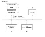
図1に、本実施形態のセンサー装置の構成例を示す。センサー装置は、マイクロプロセッサー10、センサー部20、フラッシュメモリー30(広義には不揮発性の記憶部)、RAM40(Random Access Memory、広義には揮発性の記憶部)、電圧低下検出部50、通信部60、表示部70を含む。なお、本実施形態は図1の構成に限定されず、その構成要素の一部を省略したり、他の構成要素を追加したりする等の種々の変形実施が可能である。
1. Sensor Device FIG. 1 shows a configuration example of the sensor device of the present embodiment. The sensor device includes a
マイクロプロセッサー10は、例えばMPUにより構成され、センサー装置の各部の制御や種々のデータ処理を行うためのプログラムを実行する。マイクロプロセッサー10は、処理部11、時間情報出力部12を含む。
The
処理部11は、上記プログラムを実行し、例えばセンサー部20からのセンサー検出結果のデータ処理や、フラッシュメモリー30への履歴情報の書き込み処理、通信部60を介したPCとの通信処理、センサー装置の初期化処理等を行う。
The
時間情報出力部12は、時刻表示や履歴情報に用いるための日時情報(広義には時間情報)を出力する。例えば、時間情報出力部12は、初期日時からの経過年月日や経過時分秒をカウントするカウンターにより構成され、そのカウンターのカウント値を日時情報として出力する。
The time
センサー部20は、ユーザーの生体情報や運動情報のセンシングを行い、センサー検出結果を出力する。センサー部20は、例えば図示しないセンサーとA/D変換部を有し、A/D変換部が、センサーが出力するアナログ信号をA/D変換し、センサー部20が、そのA/D変換されたデジタル信号をセンサー検出結果として出力する。例えば、センサー部は、赤外線センサーや音響センサー、加速度センサー、血糖センサーなどにより構成され、脈拍情報や血圧情報、歩数情報、血糖値情報などのセンシングを行う。
The
フラッシュメモリー30は、電源オン・オフに依らず記憶データを保持するメモリーであり、種々のデータの保存に用いられる。例えば、フラッシュメモリー30には、運動履歴情報データや、ユーザーの設定情報データ(例えば体重、性別、年齢など)などが、マイクロプロセッサー10により書き込まれる。また、フラッシュメモリー30には、マイクロプロセッサー10が実行する種々のプログラムデータが格納されている。
The
RAMは、一時的なデータ記憶に用いられるメモリーであり、例えばSRAMやDRAMにより構成される。例えばRAMは、マイクロプロセッサー10がプログラムを実行する際のワーキングメモリーとして用いられる。また、RAMには、センサー装置の現在日時を表す日時情報が記憶され、その日時情報は、時間情報出力部12からの日時情報により順次更新される。
The RAM is a memory used for temporary data storage, and is composed of, for example, SRAM or DRAM. For example, the RAM is used as a working memory when the
電圧低下検出部50は、図示しない電源(センサー装置の電源、例えば二次電池)からの電源電圧が所定電圧よりも小さくなった場合、処理部11に対して検出信号を出力する。処理部11は、検出信号を受け取ると、センサー装置を省電力モードに設定する。省電力モードでは、時間情報出力部12及びRAM40以外の構成要素の動作を停止し、電力消費を節約する。即ち、日時情報の更新のみが行われ、処理部11によるデータ処理やセンサー部20によるセンシング、通信部60による通信処理、表示部70による表示処理が停止される。
The voltage
例えば、電圧低下検出部50は、図示しないダイオードと分圧回路を有し、電源電圧を分圧回路により分圧した電圧と、ダイオードの両端の電圧を比較することにより、電源電圧が所定電圧より小さくなったことを検出する。
For example, the voltage
通信部60は、センサー装置の外部(例えば図3に示すクレードル110やPC200)との通信処理を行う。通信処理は、無線通信処理であってもよいし、有線通信処理であってもよい。例えば、無線LANやBluetooth、USB等の種々の通信規格に準拠した通信処理であってもよいし、独自規格の通信処理であってもよい。
The
表示部70は、例えば液晶表示装置により構成され、日時や運動履歴、生体情報(例えば血圧、脈拍)、運動情報(例えば運動継続時間、消費カロリー、歩数)、ユーザー設定情報(例えば身長、体重、年齢)などを表示する。
The
2.初期化処理における日時情報設定処理
次に、上述のセンサー装置が行う初期化処理において、センサー装置に残された日時情報を用いて日時設定を行う処理について説明する。
2. Date / Time Information Setting Processing in Initialization Processing Next, processing for setting date / time using the date / time information remaining in the sensor device in the initialization processing performed by the sensor device described above will be described.
ここで、初期化処理(リセット処理)とは、センサー装置がリセットされた状態からセンサー装置を立ち上げ(ブート処理)、センサー装置をユーザーが操作可能な状態にする処理である。例えば本実施形態では、電源電圧が低下すると省電力モードで動作し、その後、電源が充電又は交換されて電源電圧が上昇すると、センサー装置が起動可能な状態となる。ユーザーが起動操作を行うとマイクロプロセッサー10が初期化処理プログラムを実行し、各部の起動やRAM40の初期化を行う。
Here, the initialization process (reset process) is a process of starting the sensor device from a state in which the sensor device has been reset (boot process) and making the sensor device operable by the user. For example, in this embodiment, when the power supply voltage decreases, the sensor device operates in the power saving mode. After that, when the power supply is charged or exchanged and the power supply voltage increases, the sensor device can be activated. When the user performs an activation operation, the
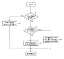
図2に、初期化処理における日時情報設定処理(広義には時間情報設定処理)のフローチャートを示す。図2に示すように、この処理が開始されると、RAM40に保持された日時情報(広義には時間情報)の値の正当性を判定する(ステップS1)。この正当性は、RAM40に保持された日時情報の値が、所定範囲内であるか否かにより判定する。所定範囲は、例えば下記に示す範囲である。
年:出荷年(例えば2011)〜2099
月:1〜12
日:1〜31
時:0〜23
分:0〜59
秒:0〜59
FIG. 2 shows a flowchart of date information setting processing (time information setting processing in a broad sense) in the initialization processing. As shown in FIG. 2, when this process is started, the validity of the value of the date / time information (time information in a broad sense) held in the
Year: Shipment year (for example, 2011) to 2099
Month: 1-12
Day: 1-31
Hours: 0-23
Minute: 0-59
Seconds: 0-59
この正当性の判定では、RAM40に記憶されたデータが破壊されているか否かを判定している。例えば、電源電圧の低下によりRAM40が記憶データを保持できず、記憶データが破壊されている場合には、RAM40上の日時情報は“00”や“FF”などの値にデータ化けする。本実施形態では、現実に存在する年月日や時分秒の範囲を条件とすることで、このような破壊されたデータを整合性のないデータとして除外する。
In the determination of validity, it is determined whether or not the data stored in the
RAM40上の値に正当性がある場合には、RAM40上の値を日時情報として設定し(ステップS2)、処理を終了する。RAM40上の値に正当性がない場合には、フラッシュメモリー30に日別履歴データが存在するか否かの確認を行う(ステップS3)。
If the value on the
日別履歴データが存在する場合には、その日別履歴データの中の、直近に行われた計測の年月日の情報を、日時情報として設定し(ステップS4)、処理を終了する。日時情報のうち時分秒の情報は、例えば00時00分00秒に設定してもよいし、履歴データの中に時分秒の情報があれば、その情報を利用してもよい。日別履歴データが存在しない場合には、所定の初期値(例えば2011年1月1日(土)00時00分00秒)を、日時情報として設定し(ステップS5)、処理を終了する。 If the daily history data exists, the date information of the most recently measured date in the daily history data is set as the date / time information (step S4), and the process is terminated. Of the date / time information, the hour / minute / second information may be set to 00:00:00, for example, or if the history data includes the hour / minute / second information, the information may be used. If the daily history data does not exist, a predetermined initial value (for example, January 1, 2011 (Saturday) 00:00:00) is set as the date / time information (step S5), and the process is terminated.
以上の処理は、初期化処理においてRAM40の記憶内容が初期化される前に行われ、この処理の日時情報の設定により、時間情報出力部12のカウント開始時間が設定される。そして、RAM40の記憶内容が初期化された後に、時間情報出力部12がRAM40の日時情報を更新する。
The above processing is performed before the stored contents of the
3.測定システム
さて、時計機能を持つ製品では、多くの製品は電池切れによるリセット処理がかかった際に、日付と時間を初期時刻に設定する。例えば、2011年に発売されたものだった場合、日付と時間を「2011年1月1日(土)00時00分00秒」に設定する。
3. Measurement System Now, for products with a clock function, many products set the date and time as the initial time when a reset process occurs due to battery exhaustion. For example, if it was released in 2011, the date and time are set to “January 1, 2011 (Saturday) 00:00:00”.
このような製品は、計測データを保持する必要がなく、任意のアプリケーションに使用するデータをアップロードするといった機能を持たないという前提で作られている。そのため、計測データを蓄積し、その計測データをアプリケーションで用いようとすると、過去の計測データと時間の整合性が無いデータがアップロードされるという課題がある。この点について、以下に詳細に説明する。 Such a product is made on the premise that it does not need to store measurement data and does not have a function of uploading data used for an arbitrary application. For this reason, if measurement data is accumulated and the measurement data is to be used in an application, there is a problem in that data that does not have time consistency with past measurement data is uploaded. This point will be described in detail below.
なお以下では、上述のセンサー装置100が、赤外線センサーにより脈拍をセンシングする脈拍センサー装置である場合を例に説明するが、本実施形態はこれに限定されず、種々のセンサー装置を利用できる。
In the following, a case where the above-described
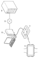
まず、図3に上述のセンサー装置を用いた測定システムの構成例を示す。測定システムは、センサー装置100、クレードル110、PC200(パーソナルコンピュータ)、サーバーシステム400を含む。
First, FIG. 3 shows a configuration example of a measurement system using the above-described sensor device. The measurement system includes a
センサー装置100は、ユーザーの脈拍をセンシングし、その脈拍やユーザーの体重、身長、年齢に基づいて、例えば消費カロリーなどの運動情報を取得する。センサー装置100は、その運動情報と取得日時を、履歴情報として蓄積する。
The
ユーザーがセンサー装置100のボタンを操作し、履歴情報の送信を実行すると、履歴情報が無線通信によりクレードル110に送信される。クレードル110は、有線通信(例えばUSB)によりPC200に接続されており、センサー装置100からの履歴情報を、その有線通信を介してPC200に送信する。
When the user operates the button of the
PC200には、センサー装置100と連携するためのソフトウェアが予めインストールされており、センサー装置100からの履歴情報は、そのソフトウェアによりネットワーク300を介してサーバーシステム400に送信される。
Software for cooperating with the
ネットワーク300(配信網、通信回線)は、例えばインターネットや無線LAN等を利用した通信路であり、直接接続のための専用線(専用ケーブル)やイーサネット(登録商標)等によるLANの他、電話通信網やケーブル網や無線LAN等の通信網を含むことができる。また通信方法については有線/無線を問わない。 The network 300 (distribution network, communication line) is a communication path using, for example, the Internet or a wireless LAN. In addition to a LAN using a dedicated line (dedicated cable) or Ethernet (registered trademark) for direct connection, telephone communication A communication network such as a network, a cable network, or a wireless LAN can be included. The communication method may be wired / wireless.
サーバーシステム400は、ネットワーク300を介してユーザーに運動プログラムサービスを提供する。即ち、サーバーシステム400は、PC200からネットワーク300を介して受信した履歴情報をデータ処理し、例えば消費カロリーの時系列情報などの表示用データを生成し、その表示用データをネットワーク300を介してPC200に送信する。例えば、表示用データはHTML形式で提供され、PC200は、その表示用データをウェブブラウザーにより表示部に表示する。
The
図4に、測定システムによりPC200の表示部に表示される表示画像の例を示す。図4のA1は、ウェブブラウザーの表示領域を表している。A2〜A4に示すように、ウェブブラウザーの表示領域には、ユーザー設定情報の表示領域、メニュー表示領域、履歴情報表示領域が設けられる。
FIG. 4 shows an example of a display image displayed on the display unit of the
ユーザー設定情報の表示領域には、ユーザーの現在の体重や、目標体重、目標達成率が表示される。メニュー表示領域には、ユーザーが運動プログラムサービスを操作するためのメニューが表示される。履歴情報表示領域には、センサー装置100から送信された履歴情報に基づいて、日々の運動情報(運動結果)が時系列に表示される。また、履歴情報表示領域には運動プログラムサービスが提供される実施期間が表示され、ユーザーは、その実施期間内の目標達成を目指す。
In the display area of the user setting information, the user's current weight, target weight, and target achievement rate are displayed. In the menu display area, a menu for the user to operate the exercise program service is displayed. In the history information display area, daily exercise information (exercise results) is displayed in time series based on the history information transmitted from the
このような測定システムにおいて、センサー装置100に電池切れによるリセット処理がかかり、日付が自動的に「2011年1月1日(土)00時00分00秒」の初期時刻に設定されたとする。
In such a measurement system, it is assumed that the
この場合、ユーザーが充電を終え、初期時刻に設定されていることに気付かない状態で運動計測を行うと、「2011年1月1日(土)00時00分00秒」の計測データが生成されることになる。この計測データを、開始日と終了日が定められた期間内で実施している運動プログラムサービスにアップロードすると、次のような課題が発生する。 In this case, if exercise measurement is performed in a state where the user has finished charging and is unaware that the initial time has been set, measurement data of “Saturday, January 1, 2011 00:00:00” is generated. Will be. When this measurement data is uploaded to an exercise program service that is carried out within a period in which a start date and an end date are determined, the following problems occur.
即ち、初期時刻の運動データは、運動プログラムサービスで設定されている実施期間から大きく外れてしまうため、プログラム対象データとして不適合とされるという課題が発生する。例えば実施期間が2011年10月1日〜2012年3月31日である場合、初期時刻2011年1月1日の計測データは、実施期間内のデータではなく実施期間との整合性がとれないデータであると判断される。 That is, the exercise data at the initial time greatly deviates from the execution period set in the exercise program service, and thus there is a problem that the exercise data is not suitable as the program target data. For example, when the implementation period is from October 1, 2011 to March 31, 2012, the measurement data of the initial time January 1, 2011 is not data within the implementation period and is not consistent with the implementation period. Judged to be data.
この場合、計測データはユーザーの運動実績として使用されず、ウェブブラウザーの運動履歴には表示されなくなってしまう。また、運動プログラムサービスに参加しているユーザーの中で、運動実績のランキングサービスを行う場合、初期時刻の計測データはランキングに反映されないことになる。 In this case, the measurement data is not used as the user's exercise performance and is not displayed in the exercise history of the web browser. In addition, when performing an exercise performance ranking service among users participating in the exercise program service, the measurement data of the initial time is not reflected in the ranking.
また、センサー装置100が電池切れしたときにユーザーが時刻を再設定すればよいが、リセットがかかるたびに「2011年1月1日(土)00時00分00秒」に設定されてしまうため、現在の時刻へ修正を行う際のキー操作が多くなり、リセットされる都度発生する時刻修正がユーザーにとって負担となってしまう。
In addition, the user may reset the time when the battery of the
この点、本実施形態によれば、図1で説明したようにセンサー装置は、センサー検出情報を出力するセンサー部20と、時間情報(例えば日時情報)を出力する時間情報出力部12と、不揮発性の記憶部(例えばフラッシュメモリー30)と、センサー検出情報と時間情報とを関連付けた情報を履歴情報として不揮発性の記憶部に記憶する処理部11を含む。図2のS3、S4で説明したように、処理部11は、システム(センサー装置100)の初期化処理において、不揮発性の記憶部から履歴情報を読み出し、履歴情報に含まれる時間情報をシステムの時間情報として設定する。
In this regard, according to the present embodiment, as described in FIG. 1, the sensor device includes a
例えば本実施形態では、図5に示すように、運動計測処理において、処理部11はRAM40とセンサー部20を参照して時間情報とセンサー検出情報を取得し、センサー検出情報と時間情報を関連付けて日別の運動履歴情報としてフラッシュメモリー30に格納する。なお、センサー検出情報と時間情報を関連付けた情報は、センサー検出情報(例えば脈拍情報)そのものと時間情報を関連付けた情報であってもよいし、センサー検出情報を処理して得られる情報(例えば消費カロリー情報)と時間情報を関連付けた情報であってもよい。
For example, in the present embodiment, as illustrated in FIG. 5, in the motion measurement process, the
また本実施形態では、図6に示すように、初期化処理において、処理部11はフラッシュメモリー30から読み出した履歴情報の中から時間情報を取り出し、その時間情報を時間情報出力部12に設定する。時間情報出力部12は、設定された時間情報から時間のカウントを開始し、システムの時間情報を出力する。
In the present embodiment, as shown in FIG. 6, in the initialization process, the
なお、上記の図5、図6や、後述する図7、図8では、図示を簡単にするため、電圧低下検出部50や通信部60、表示部70を省略している。
In FIGS. 5 and 6 and FIGS. 7 and 8 described later, the voltage
ここで、不揮発性の記憶部とは、電源が非供給状態であっても記憶データが保持される記憶部である。例えば、不揮発性の記憶部は、EEPROM(例えばフラッシュメモリー)や、ハードディスクドライブ等により実現できる。 Here, the nonvolatile storage unit is a storage unit that holds stored data even when power is not supplied. For example, the nonvolatile storage unit can be realized by an EEPROM (for example, flash memory), a hard disk drive, or the like.
このようにすれば、センサー装置100において履歴情報の整合性を保証する機能を提供できる。即ち、仮にユーザーが初期時刻を設定し忘れて運動した場合であっても、作成される履歴情報が、運動プログラムサービスの実施期間内の運動データとなるため、整合性のとれたデータを作成できる。また、履歴情報を参照し、その履歴情報に基づいて自動的に日時修正を行えるため、初期値「2011年1月1日(土)00時00分00秒」から手動で修正するよりも手軽に日時修正を行うことができる。例えば、日時の修正時間を短縮できるため、ユーザーの煩わしさが軽減される。
In this way, the
また本実施形態では、処理部11は、履歴情報に含まれる時間情報のうちの直近の時間情報、又はその直近の時間情報から所定時間(例えば1日)経過させた時間情報を、システムの時間情報として設定する。
Further, in the present embodiment, the
ここで、直近の時間情報とは、履歴情報に記録された時間情報のうち最も後の(最新の)時間情報である。例えば、2011年10月1日〜2011年10月15日の履歴情報がある場合、2011年10月15日が直近の時間情報である。なお、直近の時間情報は、最も後の時間情報に限定されず、最も後の時間情報から所定時間(例えば3日)以内の時間情報であればよい。 Here, the latest time information is the latest (latest) time information among the time information recorded in the history information. For example, when there is history information from October 1, 2011 to October 15, 2011, October 15, 2011 is the latest time information. The latest time information is not limited to the latest time information, and may be time information within a predetermined time (for example, three days) from the latest time information.
このようにすれば、既に履歴情報が存在する場合に、その履歴情報と整合性のあるデータを計測できる。即ち、初期化処理後に測定されたデータを、既に測定された履歴情報よりも後の日時のデータとして記録でき、できるだけ実際の測定時間に近い時間の計測データとして記録できる。 In this way, when history information already exists, data that is consistent with the history information can be measured. That is, the data measured after the initialization process can be recorded as date and time data later than the already measured history information, and can be recorded as measurement data of a time as close as possible to the actual measurement time.
また本実施形態では、図2のS3、S5で説明したように、処理部11は、不揮発性の記憶部に履歴情報が存在しない場合には、所定の初期値(例えば「2011年1月1日(土)00時00分00秒」)をシステムの時間情報として設定する。
In the present embodiment, as described in S3 and S5 in FIG. 2, the
このようにすれば、履歴情報が存在しない場合、即ちセンサー装置100が工場出荷時の状態である場合や一度も使用されていない状態である場合に、初期化処理後の時間として初期値を設定できる。
In this way, when there is no history information, that is, when the
また本実施形態では、図1で説明したように、センサー装置100は、時間情報出力部12からの時間情報を、システムの時間情報として記憶するRAM40を含む。図2のS1、S2に示すように、処理部11は、システムの初期化処理において、RAM40に保持されている時間情報をシステムの時間情報として設定する。
In the present embodiment, as described with reference to FIG. 1, the
具体的には、処理部11は、RAM40に保持されている時間情報が、システムの時間情報として正当であるか否かの判定を行い、正当であると判定した場合には、RAM40に保持されている時間情報をシステムの時間情報として設定する。
Specifically, the
例えば本実施形態では、電源電圧が低下して処理部11が動作を停止した後、電源電圧が時間情報出力部12の動作可能電圧より低くなるまでは、RAM40の時間情報が更新される。時間情報出力部12が電源電圧低下により停止した後も、電源電圧がRAM40の記憶保持可能電圧より低くなるまでは、時間情報出力部12が最後に出力した時間情報がRAM40に保持されている可能性がある。
For example, in the present embodiment, the time information in the
図7に示すように、初期化処理において、処理部11は、RAM40の時間情報記憶領域を参照し、RAM40に保持された時間情報を取得する。処理部11は、取得した時間情報が正当な場合には、その時間情報を時間情報出力部12に設定する。例えば、充電前の電源電圧がRAM40の記憶保持可能電圧より低い場合、時間情報は破壊されて異常な数値のデータとなっており、そのような場合には非正当なデータと判定する。時間情報出力部12は、設定された時間情報からカウントを開始する。
As shown in FIG. 7, in the initialization process, the
このようにすれば、初期化処理の開始前(例えば充電開始前)までRAM40に時間情報が保持されていた場合に、その保持された時間情報を利用して初期化処理において自動的に時刻設定できる。RAM40には、時間情報出力部12からの時間情報が記憶されているため、履歴情報を用いる場合よりも更に現実の測定時間に近い時間を設定できる。
In this way, when time information is held in the
また本実施形態では、図2のS1、S3、S4や図6に示すように、処理部11は、RAM40に保持されている時間情報が、システムの時間情報として正当でないと判定された場合には、不揮発性の記憶部から履歴情報を読み出し、その履歴情報に含まれる時間情報をシステムの時間情報として設定する。
In the present embodiment, as shown in S1, S3, S4 of FIG. 2 and FIG. 6, the
このようにすれば、RAM40の時刻情報が電源電圧の低下により破壊されていた場合であっても、できるだけ現実の日時に近いと考えられる履歴情報の時間情報を用いて時間情報の修正を行うことができる。
In this way, even when the time information of the
また本実施形態では、図2のS1で説明したように、処理部11は、RAM40に保持されている時間情報が、所定の時間範囲内である場合に、システムの時間情報として正当であると判定する。
In the present embodiment, as described in S1 of FIG. 2, the
このようにすれば、RAM40に残された時間情報が実際には存在し得ない時間範囲であった場合に、その時間情報が正当なものでないと判定できる。これにより、電源電圧の低下などにより破壊された時間情報により、でたらめな時刻が設定されることを避けられる。
In this way, when the time information remaining in the
また本実施形態では、図1で説明したように、処理部11は、システムの電源電圧が所定電圧よりも低下した場合に、システムを省電力モードに設定する。図8に示すように、省電力モードにおいて、処理部11は履歴情報の取得を停止し、時間情報出力部12はRAM40に対して時間情報の出力を継続する。
In the present embodiment, as described with reference to FIG. 1, the
このようにすれば、電源電圧が低下してユーザーからはセンサー装置の機能が停止して見える状態となった後も、電力消費を最小限に抑えながら可能な限り長い期間、システムの時間情報を更新し続けることができる。これにより、充電後の初期化処理において、可能な限り実際の日時に近い時間情報を設定できる。 In this way, even after the power supply voltage drops and the sensor device appears to stop functioning for the user, the system time information is kept for as long as possible while minimizing power consumption. Can continue to update. Thereby, in the initialization process after charging, time information as close as possible to the actual date and time can be set.
また本実施形態では、図3で説明したように、測定システムは、センサー装置100と表示用データ生成部を含む。表示用データ生成部は、不揮発性の記憶部に記憶された履歴情報を取得し、取得した履歴情報に基づいて測定結果の表示用データを生成する。
In the present embodiment, as described with reference to FIG. 3, the measurement system includes the
具体的には表示用データ生成部は、取得した履歴情報のうち、センサー検出情報に関連付けられた時間情報が計測期間(実施期間)内である履歴情報を用いて、測定結果の表示用データを生成する。 Specifically, the display data generation unit uses the history information in which the time information associated with the sensor detection information is within the measurement period (implementation period) of the acquired history information, and displays the display data of the measurement result. Generate.
例えば図3の測定システムでは、サーバーシステム400が表示用データ生成部に対応し、表示用データ生成部は、ネットワーク300を介して履歴情報を取得し、生成した表示用データをネットワーク300を介してPC200の表示部に表示させる。なお、本実施形態はこれに限定されず、ネットワーク300やサーバーシステム400を用いず、PC200がスタンドアローンとして履歴情報を取得し、表示用データを生成してもよい。
For example, in the measurement system of FIG. 3, the
このようにすれば、センサー装置を用いた運動測定システムを構成できる。上述の運動プログラムサービスのようにサービス実施期間が決まっている場合、本実施形態のように初期化処理において時刻情報が自動的に設定されることにより、時刻設定に煩わされることなくすぐに計測を開始でき、サービス実施期間内のデータとして用いることができる。 In this way, a motion measuring system using the sensor device can be configured. When the service implementation period is fixed as in the exercise program service described above, the time information is automatically set in the initialization process as in this embodiment, so that measurement can be performed immediately without bothering the time setting. It can be started and used as data within the service implementation period.
4.脈拍センサー装置
図9、図10に、脈拍センサー装置の構成例を示す。図9に示すように、脈拍センサー装置は、ユーザーの手首に脈拍センサー装置を固定するためのベルト130、筐体120、時刻や計測情報を表示するための表示部140、電源のオン・オフ状態や充電状態を表示するためのLED150、ユーザーが脈拍センサー装置を操作するための複数のボタン161〜164を含む。
4). Pulse Sensor Device FIGS. 9 and 10 show a configuration example of the pulse sensor device. As shown in FIG. 9, the pulse sensor device includes a
表示部140が全画面オフの電池切れの状態となった後、図3のクレードル110に脈拍センサー装置をセットして充電を開始すると、LED150が点灯するとともに表示部140の画面表示がオンになる。このとき、表示部140には、充電前の一番新しい履歴の計測終了時の時間、又は、RAM40に残っていた時間が表示される。
After the
また図10に示すように、脈拍センサー装置は、クレードル110の充電用端子又は充電アダプターの端子に接続される充電用端子170と、脈拍センサー部180を含む。脈拍センサー部180は、ベルト130によりユーザーの手首に接触され、手首の血管の拍動をセンシングする。具体的には、脈拍センサー部180は、手首に向かって赤外線を出射する光源部181と、手首からの赤外線の反射光を検出するフォトセンサー182を含む。血管の拍動により、赤外線の反射光量が変化し、その変化をフォトセンサー182で検出することで、脈拍が検出される。
As shown in FIG. 10, the pulse sensor device includes a charging
なお、上記のように本実施形態について詳細に説明したが、本発明の新規事項および効果から実体的に逸脱しない多くの変形が可能であることは当業者には容易に理解できるであろう。従って、このような変形例はすべて本発明の範囲に含まれるものとする。例えば、明細書又は図面において、少なくとも一度、より広義又は同義な異なる用語と共に記載された用語は、明細書又は図面のいかなる箇所においても、その異なる用語に置き換えることができる。またセンサー装置、測定システム等の構成、動作も本実施形態で説明したものに限定に限定されず、種々の変形実施が可能である。 Although the present embodiment has been described in detail as described above, it will be easily understood by those skilled in the art that many modifications can be made without departing from the novel matters and effects of the present invention. Accordingly, all such modifications are intended to be included in the scope of the present invention. For example, a term described with a different term having a broader meaning or the same meaning at least once in the specification or the drawings can be replaced with the different term in any part of the specification or the drawings. Further, the configuration and operation of the sensor device, the measurement system, and the like are not limited to those described in the present embodiment, and various modifications can be made.
10 マイクロプロセッサー、11 処理部、12 時間情報出力部、
20 センサー部、30 フラッシュメモリー、50 電圧低下検出部、
60 通信部、70 表示部、100 センサー装置、110 クレードル、
120 筐体、130 ベルト、140 表示部、161〜164 ボタン、
170 充電用端子、180 脈拍センサー部、181 光源部、
182 フォトセンサー、300 ネットワーク、400 サーバーシステム
10 microprocessor, 11 processing unit, 12 hour information output unit,
20 sensor unit, 30 flash memory, 50 voltage drop detection unit,
60 communication unit, 70 display unit, 100 sensor device, 110 cradle,
120 housing, 130 belt, 140 display unit, 161-164 buttons,
170 charging terminal, 180 pulse sensor unit, 181 light source unit,
182 Photosensor, 300 network, 400 server system
Claims (7)
時間情報を出力する時間情報出力部と、
不揮発性の記憶部と、
前記センサー検出情報と前記時間情報とを関連付けた情報を、履歴情報として前記不揮発性の記憶部に記憶させる処理部と、
前記時間情報出力部からの前記時間情報を、システムのシステム時間情報として記憶するRAMと、
を含み、
前記処理部は、
前記システムの初期化処理において、前記RAMに記憶されている前記時間情報が、前記システム時間情報として正当であるか否かの判定を行い、正当であると判定した場合には、前記RAMに記憶されている前記時間情報を前記システム時間情報として設定し、正当でないと判定した場合には、前記不揮発性の記憶部から前記履歴情報を読み出し、前記履歴情報に含まれる前記時間情報を前記システム時間情報として設定することを特徴とするセンサー装置。 A sensor unit that outputs sensor detection information;
A time information output unit for outputting time information;
A non-volatile storage unit;
A processing unit that stores information associating the sensor detection information with the time information in the nonvolatile storage unit as history information;
RAM for storing the time information from the time information output unit as system time information of a system;
Including
The processor is
In the initialization process of the system, it is determined whether or not the time information stored in the RAM is valid as the system time information. If it is determined that the time information is valid, the time information is stored in the RAM. the time information is set as the system time information, when it is determined not valid, reading the history information from said nonvolatile storage unit, the said time information included in the history information system A sensor device that is set as time information.
時間情報を出力する時間情報出力部と、
不揮発性の記憶部と、
前記センサー検出情報と前記時間情報とを関連付けた情報を、履歴情報として前記不揮発性の記憶部に記憶させる処理部と、
前記時間情報出力部からの前記時間情報を、システムのシステム時間情報として記憶するRAMと、
を含み、
前記処理部は、
前記システムの初期化処理において、前記不揮発性の記憶部から前記履歴情報を読み出し、前記履歴情報に含まれる前記時間情報を前記システム時間情報として設定し、
前記初期化処理において、前記RAMに記憶されている前記時間情報が、所定の時間範囲内である場合には、前記システム時間情報として正当であると判定し、前記RAMに記憶されている前記時間情報を前記システム時間情報として設定することを特徴とするセンサー装置。 A sensor unit that outputs sensor detection information;
A time information output unit for outputting time information;
A non-volatile storage unit;
A processing unit that stores information associating the sensor detection information with the time information in the nonvolatile storage unit as history information;
RAM for storing the time information from the time information output unit as system time information of a system;
Including
The processor is
In the initialization process of the system, reading the history information from said nonvolatile storage unit, and sets the time information included in the history information as the system time information,
In the initialization process, when the time information stored in the RAM is within a predetermined time range, it is determined that the system time information is valid, and the time stored in the RAM is determined. A sensor device characterized in that information is set as the system time information .
時間情報を出力する時間情報出力部と、
不揮発性の記憶部と、
前記センサー検出情報と前記時間情報とを関連付けた情報を、履歴情報として前記不揮発性の記憶部に記憶させる処理部と、
前記時間情報出力部からの前記時間情報を、システムのシステム時間情報として記憶するRAMと、
を含み、
前記処理部は、
システムの初期化処理において、前記不揮発性の記憶部から前記履歴情報を読み出し、前記履歴情報に含まれる前記時間情報を前記システムのシステム時間情報として設定し、
前記システムの電源電圧が所定電圧よりも低下した場合に、前記処理部は前記システムを省電力モードに設定し、前記省電力モードにおいて、前記処理部は前記履歴情報の取得を停止し、前記時間情報出力部は前記RAMに対して前記時間情報の出力を継続し、前記省電力モードに設定された後の前記初期化処理において、前記処理部は、前記RAMに記憶されている前記時間情報を前記システム時間情報として設定することを特徴とするセンサー装置。 A sensor unit that outputs sensor detection information;
A time information output unit for outputting time information;
A non-volatile storage unit;
A processing unit that stores information associating the sensor detection information with the time information in the nonvolatile storage unit as history information;
RAM for storing the time information from the time information output unit as system time information of a system;
Including
The processor is
In the initialization process of the system, the history information is read from the nonvolatile storage unit, the time information included in the history information is set as the system time information of the system ,
When the power supply voltage of the system drops below a predetermined voltage, the processing unit sets the system to a power saving mode, and in the power saving mode, the processing unit stops acquiring the history information and the time The information output unit continues to output the time information to the RAM. In the initialization process after the power saving mode is set, the processing unit stores the time information stored in the RAM. The sensor device is set as the system time information .
前記処理部は、
前記履歴情報に含まれる前記時間情報のうちの直近の時間情報、又は前記直近の時間情報から所定時間経過した時間情報を、前記システム時間情報として設定することを特徴とするセンサー装置。 In any one of Claims 1 thru | or 3 ,
The processor is
A sensor device characterized in that the latest time information in the time information included in the history information or time information after a predetermined time has elapsed from the latest time information is set as the system time information.
前記処理部は、
前記不揮発性の記憶部に前記履歴情報が記憶されていない場合には、所定の初期値を前記システム時間情報として設定することを特徴とするセンサー装置。 In claim 4 ,
The processor is
When the history information is not stored in the nonvolatile storage unit, a predetermined initial value is set as the system time information.
前記不揮発性の記憶部に記憶された前記履歴情報を取得し、取得した前記履歴情報に基づいて測定結果の表示用データを生成する表示用データ生成部と、
を含み、
前記処理部は、
システムの初期化処理において、前記不揮発性の記憶部から前記履歴情報を読み出し、前記履歴情報に含まれる前記時間情報を前記システムのシステム時間情報として設定することを特徴とする測定システム。 A sensor device according to any of claims 1 to 5,
A display data generation unit that acquires the history information stored in the nonvolatile storage unit, and generates display data of measurement results based on the acquired history information;
Including
The processor is
In a system initialization process, the history information is read from the nonvolatile storage unit, and the time information included in the history information is set as system time information of the system.
前記表示用データ生成部は、
取得した前記履歴情報のうち、前記センサー検出情報に関連付けられた前記時間情報が計測期間内である前記履歴情報を用いて、前記測定結果の表示用データを生成することを特徴とする測定システム。 In claim 6 ,
The display data generation unit
A measurement system for generating display data of the measurement result by using the history information in which the time information associated with the sensor detection information is within a measurement period among the acquired history information.
Priority Applications (1)
| Application Number | Priority Date | Filing Date | Title |
|---|---|---|---|
| JP2011227058A JP5834753B2 (en) | 2011-10-14 | 2011-10-14 | Sensor device and measurement system |
Applications Claiming Priority (1)
| Application Number | Priority Date | Filing Date | Title |
|---|---|---|---|
| JP2011227058A JP5834753B2 (en) | 2011-10-14 | 2011-10-14 | Sensor device and measurement system |
Publications (3)
| Publication Number | Publication Date |
|---|---|
| JP2013085612A JP2013085612A (en) | 2013-05-13 |
| JP2013085612A5 JP2013085612A5 (en) | 2014-11-20 |
| JP5834753B2 true JP5834753B2 (en) | 2015-12-24 |
Family
ID=48530189
Family Applications (1)
| Application Number | Title | Priority Date | Filing Date |
|---|---|---|---|
| JP2011227058A Active JP5834753B2 (en) | 2011-10-14 | 2011-10-14 | Sensor device and measurement system |
Country Status (1)
| Country | Link |
|---|---|
| JP (1) | JP5834753B2 (en) |
Families Citing this family (3)
| Publication number | Priority date | Publication date | Assignee | Title |
|---|---|---|---|---|
| JP6384035B2 (en) | 2013-10-11 | 2018-09-05 | セイコーエプソン株式会社 | Portable electronic devices |
| JP6372077B2 (en) * | 2013-12-25 | 2018-08-15 | セイコーエプソン株式会社 | Biological information measuring device and method for controlling biological information measuring device |
| JP6834192B2 (en) * | 2016-06-28 | 2021-02-24 | オムロンヘルスケア株式会社 | Biological information measuring device, operating method of biological information measuring device, and operating program of biological information measuring device |
Family Cites Families (10)
| Publication number | Priority date | Publication date | Assignee | Title |
|---|---|---|---|---|
| JP3476979B2 (en) * | 1995-10-18 | 2003-12-10 | セイコーエプソン株式会社 | Portable electronic devices |
| JP4309111B2 (en) * | 2002-10-02 | 2009-08-05 | 株式会社スズケン | Health management system, activity state measuring device and data processing device |
| JP2005227038A (en) * | 2004-02-10 | 2005-08-25 | Sanyo Electric Co Ltd | Measuring instrument |
| US20060015016A1 (en) * | 2004-06-22 | 2006-01-19 | Thornton William E | Caloric balance weight control system and methods of making and using same |
| JP4778307B2 (en) * | 2005-12-14 | 2011-09-21 | テルモ株式会社 | Biological information measuring device with date display function |
| JP4714025B2 (en) * | 2006-01-06 | 2011-06-29 | 株式会社日立製作所 | Sensor node, base station, sensor network, and sensing data transmission method |
| JP4885566B2 (en) * | 2006-02-28 | 2012-02-29 | テルモ株式会社 | Care facility and / or home monitoring device |
| US20080300572A1 (en) * | 2007-06-01 | 2008-12-04 | Medtronic Minimed, Inc. | Wireless monitor for a personal medical device system |
| JP2009136377A (en) * | 2007-12-04 | 2009-06-25 | Seiko Epson Corp | Health data management device and method |
| KR101068116B1 (en) * | 2008-05-23 | 2011-09-27 | (주)한별메디텍 | Apparatus and method for sensing radial arterial pulses for noninvasive and continuous measurement of blood pressure |
-
2011
- 2011-10-14 JP JP2011227058A patent/JP5834753B2/en active Active
Also Published As
| Publication number | Publication date |
|---|---|
| JP2013085612A (en) | 2013-05-13 |
Similar Documents
| Publication | Publication Date | Title |
|---|---|---|
| JP6453938B2 (en) | Tableware for monitoring and regulating food intake | |
| JP6331384B2 (en) | Activity amount related information display device | |
| JP5923857B2 (en) | Activity meter | |
| US10175247B2 (en) | Physical change evaluation device, method, and recording medium stored with program | |
| US20170128783A1 (en) | Exercise presenting apparatus, exercise presenting method, and exercise presenting program | |
| JP2009183692A (en) | Blood glucose system having time synchronization | |
| JP2010537674A (en) | System and method for monitoring information about sleep | |
| JP5834753B2 (en) | Sensor device and measurement system | |
| JP2011050673A (en) | Device and method for detecting body movement | |
| US20200305772A1 (en) | Blood glucose measuring device, blood glucose measuring system, and method for measuring blood glucose using blood glucose measuring device | |
| US9560976B2 (en) | Medical instrument with remaining visits indicator | |
| JP6509232B2 (en) | Data management unit and method of operation thereof | |
| Gomez-Peralta et al. | Insulclock: a novel insulin delivery optimization and tracking system | |
| JP3178848U (en) | Health promotion equipment | |
| US20210166798A1 (en) | Health management device, health management method, and non-transitory recording medium storing program | |
| JP2010165088A (en) | Pedometer, and method of counting steps | |
| JP6874457B2 (en) | Information display methods, systems, programs, and information display devices | |
| JP2019053084A (en) | Biological information measurement unit | |
| US9311826B2 (en) | Energy consumption estimator | |
| CN113557573A (en) | Medication assistance information providing device, method, and program | |
| JP2016032196A (en) | Temperature compensation oscillation circuit, real time clock device and electronic apparatus | |
| CN110945574B (en) | Data receiving apparatus, transmitting apparatus, transmission system, and packet data structure | |
| US20120036343A1 (en) | Electronic apparatus and meter operable during program updating | |
| JP6212321B2 (en) | Activity amount measuring device, activity amount measuring auxiliary device | |
| TW201413438A (en) | Improved method of managing an electronic apparatus |
Legal Events
| Date | Code | Title | Description |
|---|---|---|---|
| A521 | Written amendment |
Free format text: JAPANESE INTERMEDIATE CODE: A523 Effective date: 20141002 |
|
| A621 | Written request for application examination |
Free format text: JAPANESE INTERMEDIATE CODE: A621 Effective date: 20141002 |
|
| A977 | Report on retrieval |
Free format text: JAPANESE INTERMEDIATE CODE: A971007 Effective date: 20150527 |
|
| A131 | Notification of reasons for refusal |
Free format text: JAPANESE INTERMEDIATE CODE: A131 Effective date: 20150602 |
|
| A521 | Written amendment |
Free format text: JAPANESE INTERMEDIATE CODE: A523 Effective date: 20150730 |
|
| TRDD | Decision of grant or rejection written | ||
| A01 | Written decision to grant a patent or to grant a registration (utility model) |
Free format text: JAPANESE INTERMEDIATE CODE: A01 Effective date: 20151006 |
|
| A61 | First payment of annual fees (during grant procedure) |
Free format text: JAPANESE INTERMEDIATE CODE: A61 Effective date: 20151019 |
|
| R150 | Certificate of patent or registration of utility model |
Ref document number: 5834753 Country of ref document: JP Free format text: JAPANESE INTERMEDIATE CODE: R150 |
|
| S531 | Written request for registration of change of domicile |
Free format text: JAPANESE INTERMEDIATE CODE: R313531 |
|
| R350 | Written notification of registration of transfer |
Free format text: JAPANESE INTERMEDIATE CODE: R350 |