JP5834409B2 - IC tag distance measuring device and IC tag - Google Patents
IC tag distance measuring device and IC tag Download PDFInfo
- Publication number
- JP5834409B2 JP5834409B2 JP2011001302A JP2011001302A JP5834409B2 JP 5834409 B2 JP5834409 B2 JP 5834409B2 JP 2011001302 A JP2011001302 A JP 2011001302A JP 2011001302 A JP2011001302 A JP 2011001302A JP 5834409 B2 JP5834409 B2 JP 5834409B2
- Authority
- JP
- Japan
- Prior art keywords
- signal
- distance measuring
- target
- phase difference
- tag
- Prior art date
- Legal status (The legal status is an assumption and is not a legal conclusion. Google has not performed a legal analysis and makes no representation as to the accuracy of the status listed.)
- Expired - Fee Related
Links
Images


Description
本発明は、ICタグの距離測定装置およびICタグに関する。 The present invention relates to an IC tag distance measuring device and an IC tag.
ICタグは、自身の識別コードなどの情報が記録されたIC(integrated circuit)とアンテナとを有し、電波を使ってリーダ/ライタ(reader/writer、以下R/Wと呼ぶ)と情報の送受信を行う装置である。ICタグは、通常、商品等の物に装着され、装着された物の管理に用いられる。近年、ICタグとR/Wの距離を測定することで、ICタグを物の管理以外にも用いるという提案がなされている。 An IC tag has an IC (integrated circuit) in which information such as its identification code is recorded and an antenna, and transmits and receives information with a reader / writer (hereinafter referred to as R / W) using radio waves. It is a device that performs. An IC tag is usually attached to an article such as a product and is used for management of the attached article. In recent years, it has been proposed to use an IC tag for purposes other than management of an object by measuring the distance between the IC tag and the R / W.
従来のICタグの距離測定方法は、例えば、R/Wが送信した電波の強度をICタグが測定し、その強度からICタグとR/Wの間の距離を特定するというものである。従って、従来の距離測定方法には、距離測定の精度が低いという問題があった。本発明は、このような問題を解決することを課題とする。 A conventional IC tag distance measurement method is, for example, that an IC tag measures the intensity of a radio wave transmitted by an R / W and specifies the distance between the IC tag and the R / W from the intensity. Therefore, the conventional distance measurement method has a problem that the accuracy of distance measurement is low. An object of the present invention is to solve such a problem.
上記の問題を解決するために、本装置の一観点によれば、送信信号をアンテナに供給して測距用電波を生成し、前記測距用電波をターゲットICタグおよび他のICタグに送信する電波送信部と、前記ターゲットICタグが第1の反射率で前記測距用電波を反射して生成する第1の反射波と前記他のICタグが前記測距用電波を反射して生成する第2の反射波との第1の合成反射波を前記アンテナで受信して第1の受信信号を生成し、前記ターゲットICタグが前記第1の反射率とは異なる第2の反射率で前記測距用電波を反射して生成する第3の反射波と前記他のICタグが前記測距用電波を反射して生成する第4の反射波との第2の合成反射波を前記アンテナで受信して第2の受信信号を生成する電波受信部と、前記第1の受信信号と前記第2の受信信号とに基づいて、前記第1の受信信号中の前記第1の反射波に対応する信号成分と前記送信信号との位相差を求める位相差算出部とを有するICタグの距離測定装置が提供される。 In order to solve the above problem, according to one aspect of the present apparatus, a transmission signal is supplied to an antenna to generate a ranging radio wave, and the ranging radio wave is transmitted to a target IC tag and another IC tag. And a first reflected wave generated by the target IC tag reflecting the distance measurement radio wave with a first reflectance and the other IC tag reflected by the distance measurement radio wave. The first combined reflected wave with the second reflected wave is received by the antenna to generate a first received signal, and the target IC tag has a second reflectance different from the first reflectance. A second combined reflected wave of the third reflected wave generated by reflecting the distance measuring radio wave and the fourth reflected wave generated by the other IC tag reflecting the distance measuring radio wave is the antenna. A radio wave receiving unit that receives the first received signal and generates a second received signal; and The distance of the IC tag having a phase difference calculation unit that obtains a phase difference between the signal component corresponding to the first reflected wave in the first reception signal and the transmission signal based on the second reception signal A measuring device is provided.
本実施の形態によれば、距離測定装置とICタグとの間の距離を高い精度で測定することができる。 According to the present embodiment, the distance between the distance measuring device and the IC tag can be measured with high accuracy.
以下、図面にしたがって本発明の実施の形態について説明する。但し、本発明の技術的範囲はこれらの実施の形態に限定されず、特許請求の範囲に記載された事項とその均等物まで及ぶものである。尚、図面が異なっても対応する部分には同一符号を付し、その説明を省略する。 Hereinafter, embodiments of the present invention will be described with reference to the drawings. However, the technical scope of the present invention is not limited to these embodiments, but extends to the matters described in the claims and equivalents thereof. In addition, the same code | symbol is attached | subjected to the corresponding part even if drawings differ, and the description is abbreviate | omitted.
(実施の形態1)
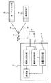
図1〜3は、本実施の形態の距離測定装置2の構成および動作を説明する図である。本距離測定装置2は、図1に示すように、電波送信部4、電波受信部6、および位相差算出部8を有している。
(Embodiment 1)
1-3 is a figure explaining the structure and operation | movement of the
電波送信部4は、発振器10、電波送信回路12、およびアンテナ14を有している。発振器10は、所定の周波数(例えば、1GHz)の送信信号を生成し、電波送信回路12に供給する。電波送信回路12はこの送信信号を増幅して、アンテナ14に供給する。アンテナ14に供給された送信信号は測距用電波16を生成し、この測距用電波16は、ターゲットICタグ18(距離測定対象のICタグ)および他のICタグ20に送信される。
The radio
図2に示すように、ターゲットICタグ18は、受信した測距用電波16を第1の反射率で反射して第1の反射波22を生成する。一方、他のICタグ20は測距用電波16を所定の反射率(例えば、第1の反射率)で反射して、第2の反射波24を生成する。第1の反射波22と第2の反射波24は、重なり合って第1の合成反射波26になる。
As shown in FIG. 2, the
更に、図3に示すように、ターゲットICタグ18は、第1の反射率とは異なる第2の反射率(例えば、第1の反射率の25%の反射率)で測距用電波16を反射して第3の反射波28を生成する。同様に、他のICタグ20は、測距用電波16を上記所定の反射率で反射して第4の反射波30を生成する。第3の反射波28と第4の反射波30は重なり合って、第2の合成反射波32になる。
Further, as shown in FIG. 3, the
図2に示すように、電波受信部6は、アンテナ14と電波受信回路22とを有している。アンテナ14は、第1の合成反射波26を受信して、第1の受信信号を生成する。生成された第1の受信信号は、電波受信回路22に供給され増幅される。同様に、アンテナ14は、図3に示すように、第2の合成反射波32を受信して、第2の受信信号を生成する。生成された第2の受信信号は、電波受信回路22に供給され増幅される。
As shown in FIG. 2, the
位相差算出部8は、増幅された第1の受信信号および増幅された第2の受信信号に基づいて、第1の受信信号中の第1の反射波に対応する信号成分と送信信号との位相差を求める。この位相差は、アンテナ14とターゲットICタグ18との間の距離に対応している。
Based on the amplified first received signal and the amplified second received signal, the phase
ところで、発振器10の生成する送信信号S0(t)は、次式で表すことができる。
By the way, the transmission signal S 0 (t) generated by the
![]()
![]()
ここで、Aは、振幅である。ωは、角振動数である。tは、時刻である。 Here, A is the amplitude. ω is the angular frequency. t is the time.
一方、第1の合成反射波26に対応する第1の受信信号S1(t)は、次式で表すことができる。
On the other hand, the first received signal S 1 (t) corresponding to the first combined
![]()
![]()
ここで、式(2)の右辺第1項は、第1の反射波22に対応する信号成分である。R1およびφ1は、この信号成分の振幅および位相(送信信号との位相差)である。式(2)の右辺第2項は、第2の反射波24に対応する信号成分である。R2およびφ2は、第2の反射波24に対応する信号成分の振幅および位相(送信信号との位相差)である。
Here, the first term on the right side of Equation (2) is a signal component corresponding to the first
同様に、第2の合成反射波32に対応する第2の受信信号S2(t)は、次式で表すことができる。
Similarly, the second received signal S 2 (t) corresponding to the second combined
![]()
![]()
ここで、式(3)の右辺第1項は、第3の反射波28に対応する信号成分である。R3およびφ3は、この信号成分の振幅および位相(送信信号との位相差)である。式(3)の右辺第2項は、第4の反射波30に対応する信号成分である。R4およびφ4は、この信号成分の振幅および位相(送信信号との位相差)である。
Here, the first term on the right side of Equation (3) is a signal component corresponding to the third
今、距離測定の間、距離測定装置2、ターゲットICタグ18、および他のICタグ20は動かないものとするとする。すると、各信号成分の位相と振幅の間には、次の関係式が成立する。
Now, it is assumed that the

ターゲットICタグ18は、第1の反射率で測距用電波を反射して第1の反射波を生成し、第2の反射率で測距用電波を反射して第3の反射波を生成する。従って、第1の反射波に対応する信号成分の振幅R1と第2の反射波に対応する信号成分の振幅R3とは、等しくはならない。
The
一方、他のICターゲット20は所定の反射率(一定値)で測距用電波を反射して、第2の反射波および第4の反射波を生成する。従って、第3の反射波に対応する信号成分の振幅R2と第4の反射波に対応する信号成分の振幅R4は等しくなる。
On the other hand, the
上述したように、距離測定の間、ターゲットICタグ18および距離測定装置2は動かないので、両装置の間隔は一定である。従って、φ1=φ3となる。同様に、距離測定の間、他のICタグ18と距離測定装置2も動かないので、φ2=φ4である。
As described above, since the
従って、第1の受信信号S1(t)と第2の受信信号S2(t)の差分を求めることで、ターゲットICタグ18からの反射波に対応する信号だけを抽出することができる。
Therefore, by obtaining the difference between the first received signal S 1 (t) and the second received signal S 2 (t), only the signal corresponding to the reflected wave from the
但し、第1の受信信号S1(t)と第2の受信信号S2(t)は、別々の時間に受信される。例えば、第1の受信信号S1(t)は、受信期間[t1,t1+Δt]で受信される。一方、第2の受信信号S2(t)は、受信期間[t2,t2+Δt]で受信される(t1とt2は異なる。)。従って、両信号の受信期間が重なるように、一方の受信期間の原点を(2π/ω)の整数倍ずらしてから、第1の受信信号S1(t)と第2の受信信号S2(t)の差分を求める。もっともこの様にしても、計算結果は、S1(t)−S2(t)と変わらない。従って、以後、このように一方の受信時間tの原点をずらして得られる受信信号の差分(例えば、S1(t)−S2(t−2πn/ω);nは整数)を、S1(t)−S2(t)で表すこととする。 However, the first received signal S 1 (t) and the second received signal S 2 (t) are received at different times. For example, the first reception signal S 1 (t) is received in the reception period [t 1 , t 1 + Δt]. On the other hand, the second reception signal S 2 (t) is received in the reception period [t 2 , t 2 + Δt] (t 1 and t 2 are different). Accordingly, the first reception signal S 1 (t) and the second reception signal S 2 ((2) are shifted after the origin of one reception period is shifted by an integral multiple of (2π / ω) so that the reception periods of both signals overlap. Find the difference of t). However, even in this way, the calculation result is the same as S 1 (t) −S 2 (t). Therefore, thereafter, the difference (for example, S 1 (t) −S 2 (t−2πn / ω); n is an integer) obtained by shifting the origin of one reception time t in this way is expressed as S 1. (T) −S 2 (t).
式(5)は、このようにして得られる第1の受信信号S1(t)と第2の受信信号S2(t)の差分(以下、演算信号と呼ぶ)である。式(5)は、演算信号が、第1の受信信号S1(t)中の第1の反射波28に対応する信号成分R1sin(ωt1+φ1)と同じ位相を有することを示している。この位相φ1は、次式で表すことができる。
Equation (5) is the difference between the first received signal S 1 (t) and the second received signal S 2 (t) obtained in this way (hereinafter referred to as a calculation signal). Equation (5) indicates that the arithmetic signal has the same phase as the signal component R 1 sin (ωt 1 + φ 1 ) corresponding to the first reflected
ここで、dは、ターゲットICタグ18と距離測定装置2(正確には、アンテナ14)との間の距離である。λは、測距用電波の波長(=2πc/ω、cは光速)である。尚、φ1の単位は、radである。
Here, d is a distance between the
式(6)から明らかなように、位相φ1は、ターゲットICタグ18と距離測定装置2の間の距離dに対応している。従って、位相φ1が分かれば、ターゲットICタグ18と距離測定装置2との間の距離dを算出することができる。距離dの算出には、次式が用いられる。
As is clear from the equation (6), the phase φ 1 corresponds to the distance d between the
式(7)には、位相φ1の単位が(rad)の場合の算出式と、位相φ1の単位が度(°)の場合の算出式とが示されている。 Formula (7) shows a calculation formula when the unit of phase φ 1 is (rad) and a calculation formula when the unit of phase φ 1 is degree (°).
位相φ1が90°で送信信号の周波数fが1GHzの場合、距離dは、式(7)より3.75cmである。ここで、位相φ1の測定精度は、数度程度である。従って、距離dの測定精度は、1mm程度である。 When the phase φ 1 is 90 ° and the frequency f of the transmission signal is 1 GHz, the distance d is 3.75 cm from the equation (7). Here, the measurement accuracy of the phase φ 1 is about several degrees. Therefore, the measurement accuracy of the distance d is about 1 mm.
距離測定装置2は、測距用電波16の反射波が生成する受信信号と送信信号の位相差に基づいて、ターゲットICタグ18までの距離を測定する。このため、他のICタグ20や電波反射体からの反射波が受信電波に混在すると、距離測定の障害になる。しかし、本実施の形態の距離測定装置2は、第1の受信信号S1(tと第2の受信信号S2(t)の差分を求めることで、このような問題を解決している。
The
ところで、送信信号の周波数が低い場合には、第1の受信信号S1(t)および第2の受信信号S2(t)をそれぞれアナログ・デジタル変換して、演算信号(=S1(t)−S2(t))を求めることは容易である。しかし、送信信号の周波数fを高くして距離dの測定精度を高くしようとすると、受信信号のアナログ・デジタル変換は困難になる。 By the way, when the frequency of the transmission signal is low, the first reception signal S 1 (t) and the second reception signal S 2 (t) are converted from analog to digital, respectively, and an arithmetic signal (= S 1 (t ) -S 2 (t)) is easy to find. However, if the frequency f of the transmission signal is increased to increase the measurement accuracy of the distance d, analog / digital conversion of the reception signal becomes difficult.
そこで、本実施の形態では、第1の受信信号S1(t)および第2の受信信号S2(t)それぞれの振幅および位相を測定し、これらの測定値に基づいて、演算信号の位相φ1を算出する。 Therefore, in the present embodiment, the amplitude and phase of each of the first reception signal S 1 (t) and the second reception signal S 2 (t) are measured, and the phase of the calculation signal is determined based on these measurement values. to calculate the φ 1.
![]()
![]()
式(8)は、第1の受信信号S1(t)を、送信信号の位相差θ1を用いて表した式である。P1は、第1の受信信号S1(t)の振幅である。同様に、式(9)は、第2の受信信号S2(t)を、送信信号の位相差θ2を用いて表した式である。P2は、第2の受信信号S2(t)の振幅である。 Expression (8) is an expression representing the first reception signal S 1 (t) using the phase difference θ 1 of the transmission signal. P 1 is the amplitude of the first received signal S 1 (t). Similarly, Expression (9) is an expression that represents the second reception signal S 2 (t) using the phase difference θ 2 of the transmission signal. P 2 is the amplitude of the second received signal S 2 (t).
式(8)および(9)を用いると、演算信号は次式のように表すことができる。 Using equations (8) and (9), the arithmetic signal can be expressed as:
ここで、Pcalおよびθcalは、次式により算出されるパラメータである。 Here, P cal and θ cal are parameters calculated by the following equations.
本実施の形態の位相算出部8は、まず、第1の受信信号S1(t)の振幅P1および位相θ1を測定する。更に、位相算出部8は、第2の受信信号S2(t)の振幅P2および位相θ2を測定する。
The
その後、位相算出部8は、式(12)に基づいて、演算信号の位相θcalを算出する。この位相θcalは、上述したように、ターゲットICタグ18までの距離に対応している。
Thereafter, the
ところで、受信信号の振幅と位相の測定は、高周波帯(例えば、GH帯)においても容易である。従って、距離測定装置2によれば、ターゲットICタグ18までの距離の測定精度を高くすることができる。
By the way, the measurement of the amplitude and phase of the received signal is easy even in a high frequency band (for example, GH band). Therefore, according to the
因みに、演算信号の位相は、第1の反射波22に対応する受信信号の位相であると同時に、第3の反射波28に対応する信号成分と送信信号との位相差でもある。従って、位相差算出部8は、増幅された第1の受信信号S1(t)および第2の受信信号S2(t)に基づいて、第2の受信信号中の第2の反射波28に対応する信号成分と送信信号との位相差を求める装置でもある。
Incidentally, the phase of the calculation signal is not only the phase of the reception signal corresponding to the first reflected
(実施の形態2)
(1)構成
図4は、本実施の形態の距離測定装置2aの構成図である。本距離測定装置2aは、例えば、携帯端末に設けられるR/Wである。
(Embodiment 2)
(1) Configuration FIG. 4 is a configuration diagram of the
距離測定装置2aは、図4に示しように、発振器10、プロセッサ34、受信側フィルタ36a、送信側直交ミキサ38a、送信側増幅器40a、サーキュレータ42、およびアンテナ14を有している。発振器10およびアンテナ14は、それぞれ実施の形態1の発振器およびアンテナと同じ機能を有している。プロセッサ34、送信側フィルタ36a、送信側直交ミキサ38a、送信側増幅器40a、およびサーキュレータ42は、実施の形態1の電波送信回路12として機能する。プロセッサ34は、CPU(Central Processing Unit)とメモリとを有している。このメモリには、以下に説明する機能をCPUに実現させるためのプログラムが記録されている。また、このメモリは、CPUが行う演算に用いられる。
As shown in FIG. 4, the
また、距離測定装置2aは、受信側増幅器40b、振幅検出器44、および位相比較器46を有している。サーキュレータ42および受信側増幅器40bは、実施の形態1の電波受信回路22として機能する。振幅検出器44、位相比較器46、およびプロセッサ34は、実施の形態1の位相算出部8として機能する。
The
また、距離測定装置2aは、受信側フィルタ36b、受信側直交ミキサ38b、および復調器48を有している。これらの装置は、ターゲットICタグ18および他のICタグ20からのデータを復調するために用いられる。
The
プロセッサ34は、後述する距離算出部およびコマンド送出部の一部としても機能する。図4に示すように、プロセッサ34は、LAN(Local Area Network)50に接続されている。LAN50は、例えば携帯端末内に設けられたネットワークであり、他のCPU等に接続されている。プロセッサ34は、このLAN50を介して他のCPU等と情報を送受信する。
The
図5は、振幅検出器44の回路図の一例である。図5に示すように、振幅検出器44は、増幅率0dBの反転増幅器54、第1のトランジスタ56a、第2のトランジスタ56b、負荷抵抗58、キャパシタ60、およびアナログ・デジタル変換器70を有している。第1のトランジスタ56aおよび第2のトランジスタ56bは、略同じ閾値を有している。
FIG. 5 is an example of a circuit diagram of the
入力端子72に入力された入力信号は、第1のトランジスタ56aのゲートおよび反転増幅器56bの入力に供給される。反転増幅器56bは、入力信号の極性を反転し、第2のトランジスタ56bのゲートに供給する。
The input signal input to the
図5に示すように、キャパシタ60の一端は接地されている。キャパシタ60の他端は、第1のトランジスタ56aおよび第2のトランジスタ56bのソースに接続されている。この第1のトランジスタ56aは、キャパシタ60の電圧と第1のトランジスタ56aの閾値の和が入力信号の最大値に達するまで、キャパシタ60を充電する。同様に、第2のトランジスタ56bは、キャパシタ60の電圧と第2のトランジスタ56bの閾値の和が反転増幅器54の出力の最大値に達するまで、キャパシタ60を充電する。一方、負荷抵抗58は、キャパシタ60を除々に放電する。
As shown in FIG. 5, one end of the
従って、キャパシタ60の両端には、入力信号の最大値より第1および第2のトランジスタ56a,56bの閾値分低い電圧が発生する。アナログ・デジタル変換器70は、この電圧をデジタル信号に変換して出力する。従って、振幅検出器44は、入力信号の振幅に略等しいデータを出力端子74から出力する。
Therefore, a voltage lower than the maximum value of the input signal by the threshold value of the first and
位相検出器46は、例えば、一対の入力信号を乗算して出力するアナログ乗算器およびその出力をアナログ・デジタル変換するアナログ・デジタル変換器を有している。従って、位相検出器46は、周波数が略等しい一対の入力信号が供給されると、入力信号の位相差に比例するデジタル信号を出力する。
The
このような構成により、本距離測定装置2aは、ターゲトICタグ18および他のICタグ20に測距用電波16を送信し、ターゲトICタグ18との間の距離に対応する位相差を測定する(図1参照)。
With this configuration, the
図6は、ターゲットICタグ18および他のICタグ20(以下、ICタグと呼ぶ)の構成を説明する構成図である。図6に示すように、ICタグ18,20は、アンテナ76、整流器78、信号抽出回路80、論理回路82、およびトランジスタ84を有している。
FIG. 6 is a configuration diagram illustrating the configuration of the
アンテナ76は、距離測定装置2が送信した電波86を受信し、整流器78および信号抽出回路80に供給する。整流器78は、アンテナ76が受信した信号を整流して直流電圧を生成し、信号抽出回路80、論理回路82、およびトランジスタ84に供給する。信号抽出回路80は、アンテナ76が受信した信号を復調してデジタル信号を生成し、論理回路82に入力する。論理回路82は、入力されたデジタル信号に含まれるコマンドおよびデータに応答して、トランジスタ84をON/OFFさせる。このON/OFF動作によりアンテナ76の反射率が変化して、反射波88が変調される。
The
(2)動作
図7は、距離測定装置2aの動作を説明するフローチャートである。距離測定装置2aは、まずターゲットICタグ18にコマンド信号を送信する(S2)。図8は、距離測定装置2aが送信するコマンド信号90の一例を説明する図である。
(2) Operation FIG. 7 is a flowchart for explaining the operation of the
コマンド信号90は、同期信号92、デリミッタ信号94、データ信号96、および誤りチェック信号(例えば、CRC信号)98を有している。データ信号96は、ユーザID(identification)領域100およびデータ/コマンド領域102を有している。
The
本距離測定装置2aは、ユーザID領域100を用いて、ターゲットICタグに割り当てられたユーザIDを送信する。また、本距離測定装置2aは、データ/コマンド領域102を用いて、ターゲットICタグ18にコマンドを送信する。コマンドの内容は、測距用電波に対する反射率を、第1の反射率と第2の反射率との間で交互に変化させよというものである。更に、本距離測定装置2aは、データ/コマンド領域102を用いて、反射率を交互に変化させる回数(例えば、100回)を送信する。尚、以下の説明では、第1の反射率は、第2の反射率より高いものとする。
The
コマンド信号90に対応するデジタル信号は、プロセッサ34により生成される。このデジタル信号は送信側フィルタ36aにより平滑化され、送信側直交ミキサ38aに入力される。送信側直交ミキサ38aは、このデジタル信号を用いて、発振器10が生成した高周波信号(例えば、1GHz)を直交変調してコマンド信号90を生成する。生成されたコマンド信号90は、送信側増幅器40a、サーキュレータ42、およびアンテナ14により無線電波に変換され、ICタグ18,20に送信される。
A digital signal corresponding to the
この無線電波を受信したターゲットICタグ18は、まずユーザID領域100からユーザIDを検出する。ターゲットICタグ18は、検出したユーザIDと自己のIDが一致することを確認し、その後データ/コマンド領域102のコマンドおよびデータに従って、測距用電波16に対する反射率を第1の反射率と第2の反射率に交互に変化させる。一方、他のICタグ20は、ユーザID領域100から検出するユーザIDと自身のIDが一致しないので、測距用電波16に対する反射率を所定の反射率(例えば、第1の反射率)に保持する。
The
すなわち、プロセッサ34等は、測距用電波に対する反射率を第1の反射率にした後、反射率を第1の反射率値とは異なる第2の反射率値にするようにターゲットICタグ18に命令するコマンドを送出するコマンド送信部として機能する。ここで、プロセッサ34等とは、プロセッサ34、送信側フィルタ36a、送信側直交ミキサ38a、発振器10、送信側増幅器40a、サーキュレータ42、およびアンテナ14である。
That is, the
次に、プロセッサ34は、送信側直交ミキサ38aのIチャネル(In-phase Channel、同相成分)およびQチャネル(Q-phase Channel、直交成分)に所定の正電圧および0Vを入力して、発振器10が生成する高周波信号(送信信号)と同相の正弦波信号を生成する。送信側増幅器40a、サーキュレータ42、およびアンテナ14は、この正弦波信号を増幅して測距用電波16を生成する。生成された測距用電波16は、ターゲットICタグ18および他のICタグ20に送信される(S4)。
Next, the
次に、プロセッサ34は、受信信号の測定回数が所定の回数に達したか否かを判定する(S6)。測定回数が所定の回数に達しない場合は、次のHi信号検出ステップ(S8)に進む。測定回数が所定の回数に達した場合には、測定を終了し位相計算ステップ(S28)に進む。尚、上記所定の回数は、ターゲットICタグが反射率を交互に変化させる回数と同数または当該回数より少ない数である。
Next, the
上述したように、ターゲットICタグ18は、ステップS2のコマンド信号90に応答して、測距用電波16に対する反射率を周期的に増減させる。この反射率の変化に従って、距離測定装置2aの受信信号の振幅も周期的に増減する。Hi信号検出ステップS8では、プロセッサ34は、振幅検出器44の出力に基づいて、受信信号レベルが高い状態(Hiレベル)に達するタイミングを検出する。
As described above, the
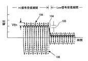
図9は、振幅検出器44の出力の時間変化を説明する図である。横軸は、時間である。縦軸は、電圧である。図9には、図5に示すキャパシタ60の両端の電圧104、トランジスタ56aのゲートに供給される受信信号の電圧106、およびトランジスタ56bのゲートに供給される反転増幅器54の出力電圧108が示されている。図9には、第1のトランジスタ56aおよび第2のトランジスタ56bの閾値Vthも示されている。また、図9には、受信信号の振幅が増加するHi信号受信期間および受信信号の振幅が減少するLow信号受信期間も示されている。
FIG. 9 is a diagram for explaining the time change of the output of the
第1のトランジスタ56aは、ゲートに供給される受信信号106がキャパシタ60の両端の電圧104と第1のトランジスタ56aの閾値Vthを超えている間導通し、キャパシタ60を充電する。同様に、第2のトランジスタ56bは、ゲートに供給される反転増幅器54の出力電圧108がキャパシタ60の両端の電圧104と第2のトランジスタ56bの閾値Vthを超えている間導通し、キャパシタ60を充電する。ここで、上述したように、第1のトランジスタ56aと第2のトランジスタ56bの閾値Vthは略同じである。
The
従って、キャパシタ60の両端の電圧104は、受信信号106の振幅(または、反転増幅器54の出力電圧108の振幅)より閾値Vth分小さい値になる。振幅検出器44は、キャパシタ60の両端の電圧104をアナログ・デジタル変換して出力する。プロセッサ34は、この出力を監視して、受信信号が高い状態(Hiレベル)に達するタイミングを検出する(S8)。
Accordingly, the
プロセッサ34は、受信信号がHiレベルに達するタイミングを検出すると、受信信号の振幅が安定するのに十分な時間(例えば、1μs)待機する(S10)。
When detecting the timing at which the received signal reaches the Hi level, the
その後、プロセッサ34は、振幅検出器44および位相比較器46の出力をメモリ(図示せず)に記録する(S12)。この時メモリに記録されるデータは、Hiレベルにおける受信信号(Hiレベル受信信号)の振幅P1および位相θ1(発振器10の生成する高周波信号とHiレベル受信信号との位相差)である。
Thereafter, the
Hi信号の振幅P1および位相θ1を記録すると、プロセッサ34は、振幅検出器44の出力を再び検出し、図9に示すように、検出した振幅がHiレベルにおける振幅から、所定の値分105(例えば3ステップ)以上減少したか否か判断する(S14,S16)。検出したデータが所定の値分減少したと判断した場合には、プロセッサ34は、次のLow信号検知ステップS18に進む。所定の値分減少しなかったと判断した場合には、プロセッサ34は、振幅検出ステップS14に戻る。
When the amplitude P 1 and the phase θ 1 of the Hi signal are recorded, the
Low信号検出ステップS18の間、プロセッサ34は振幅検出器44の出力を監視して、受信信号レベルが低い状態(Lowレベル)に達するタイミングを検知する。その後、プロセッサ34は、受信信号の振幅が安定するのに十分な時間(例えば、1μs)待機する(S20)。
During the Low signal detection step S18, the
この待機時間が経過すると、プロセッサ34は、振幅検出器44および位相比較器46の出力を検出しメモリ(図示せず)に記録する(S22)。この時メモリに記録されるデータは、Lowレベルにおける受信信号(Lowレベル受信信号)の振幅P2および位相θ2(発振器10の生成する高周波信号とLowレベル受信信号の位相差)である。
When this standby time has elapsed, the
Low信号の振幅P2および位相θ2を記録すると、プロセッサ34は、振幅検出器44の出力を再び検出し、検出した振幅がLowレベルにおける振幅から所定の値(例えば、3ステップ)以上増加したか否か判断する(S24,S26)。所定の値分増加したと判断した場合には、プロセッサ34は、ステップS6に戻る。所定の値分増加しなかったと判断した場合、プロセッサ34は、振幅検出ステップS24に戻る。
When the amplitude P 2 and the phase θ 2 of the Low signal are recorded, the
ステップS6に戻り測定回数が所定の回数に達していると判断すると、プロセッサ34は、位相差計算ステップS28に進む。位相計算ステップS28では、プロセッサ34は、実施の形態1で説明した式(12)とメモリに記録したデータに基づいて、演算信号の位相差θcalを算出する。この時、プロセッサ34は、メモリに記録された振幅P1,P2および位相θ1,θ2を平均化して、式(12)の計算に用いる。従って、本実施の形態によれば、測定精度が向上する。
Returning to step S6, if it is determined that the number of measurements has reached the predetermined number, the
更に、プロセッサ34は、次の距離計算ステップS30で、位相差θcalに対応する距離を算出する。この時、プロセッサ34は、位相差計算ステップS28で算出したθcalを式(7)のφ1として用いて距離dを算出する。このように、プロセッサ34は、第1の受信信号中の第1の反射波に対応する信号成分と送信信号との位相差に対応する距離を算出する距離算出部として機能する。
Further, the
ところで、位相差計算ステップS28で算出されるθcalの範囲は、0〜360°である。従って、距離計算ステップS30で算出される距離の範囲は、0mmからλ/2(例えば、15cm)までの範囲ある。ターゲットICタグ18が距離測定装置2aからλ/2の整数倍以上離れている場合には、実際の距離よりこのλ/2の整数倍少ない距離が、距離測定装置2aとターゲットICタグ18の距離として算出される。しかし、実施の形態3で説明するように、このような距離が算出されても、応用上問題にならない場合が多い。
By the way, the range of θ cal calculated in the phase difference calculation step S28 is 0 to 360 °. Accordingly, the distance range calculated in the distance calculation step S30 is a range from 0 mm to λ / 2 (for example, 15 cm). When the
図10は、ICタグ18,20の動作を説明する等価回路図である。図10に示すように、ICタグ18,20は、アンテン76の等価回路110、整流器78等の等価回路112、トランジスタ84の等価回路114、および論理回路82を有している。
FIG. 10 is an equivalent circuit diagram for explaining the operation of the IC tags 18 and 20. As shown in FIG. 10, the IC tags 18 and 20 include an
アンテナ76の等価回路110は、アンテナインピーダンス116(例えば、50Ω)と信号源118を有している。アンテナインピーダンス116で消費される電力が反射波の電力である。等価回路112は、アンテナ76およびトランジスタ84を除く回路全体の等価回路である。等価回路112は、一つの負荷抵抗に単純化されている。この負荷抵抗の値は、例えば50Ωである。トランジスタ84の等価回路114は、ON抵抗120とスイッチ122を有している。ON抵抗120の値は、例えば1Ωである。
The
今、論理回路82によりスイッチ122が閉じられると、アンテナの等価回路110には負荷抵抗112とON抵抗120が並列に接続された状態になる。この時、低抵抗のON抵抗120を介して、大電流がアンテナインピーダンス116に流れる。このため、アンテナ76の反射率は高くなる。
Now, when the
一方、論理回路82によりスイッチ122が開かれると、アンテナの等価回路110には負荷抵抗112のみが接続された状態になる。この時、高抵抗の負荷抵抗112を介して、微少電流がアンテナインピーダンス116に流れる。このため、アンテナ76の反射率は低くなる。ICタグ19,20は、このようにしてアンテナ76の反射率を制御する。
On the other hand, when the
(実施の形態3)
図11は、距離測定システム124の一例を説明する図である。本距離測定システム124は、実施の形態2の距離測定装置2aおよび複数のICタグ126を有している。複数のICタグ126は、図6を参照して説明したICタグである。
(Embodiment 3)
FIG. 11 is a diagram illustrating an example of the
図11に示すように、距離測定装置2aは、携帯端末130に設けられている。複数のICタグ126は、携帯端末130のユーザの指および手首に装着されている。
As shown in FIG. 11, the
距離測定装置2aは、複数のICタグ126にコマンド信号90を送信して、複数のICタグ126からターゲットICタグを順次選択する。距離測定装置2aは、ターゲットICタグを選択するたびに、図7を参照して説明した手順(S4〜S30)にしたがって、演算信号の位相差を求める。距離測定装置2aは、この位相差に基づいて、複数のICタグ126それぞれと距離測定装置2aの位置(所定の位置)との間の距離を算出する。
The
携帯端末130は、距離測定装置2aが測定した距離(または位相差)に基づいて、ユーザの手128の動きまたは形状に対応する命令を特定する。携帯端末130は、特定した命令に応答して動作する。従って、本距離測定システム124によれば、キーボードやタッチパネルによらず、携帯端末130を操作することができる。
The
ところで、距離測定システム124が算出する距離は、上述したように、測距用電波の波長の1/2の整数倍分、実際の距離と異なる場合がある。しかし、手の形状および動きは、ICタグ間の相対的な距離から推定される。従って、測定距離が実際の距離と異なっていても問題はない。
By the way, as described above, the distance calculated by the
尚、図11に示すように、携帯端末130に更に別の距離測定装置2bを設けてもよい。このように複数の距離測定装置を設けることで、ユーザの手の形状および動きをより正確に特定することができる。
In addition, as shown in FIG. 11, you may provide another
本実施の形態では、ターゲットICタグは、複数のICタグ126から選択される。しかし、ターゲットICタグと他のICタグは、固定されていてもよい。この場合、ターゲットICタグのみが、反射率を変化させるためのコマンド信号に応答するようにプログラムされる。 In the present embodiment, the target IC tag is selected from a plurality of IC tags 126. However, the target IC tag and the other IC tag may be fixed. In this case, only the target IC tag is programmed to respond to a command signal for changing the reflectivity.
本実施の形態では、距離測定装置2a,2bは、携帯端末130に設けられている。しかし、距離測定装置2a,2bは、他の情報処理装置(例えば、パーソナルコンピュータ)に設けられてもよい。
In the present embodiment, the
以上の実施の形態では、プロセッサ34から送信側直交ミキサ38aに一定強度の電圧を入力して、周波数および振幅が一定の正弦波を生成している。しかし、発振器10が生成する正弦波信号を直交ミキサ38aにより振幅変調して得られ信号を、送信信号として用いてもよい。但し、発振器10が生成する正弦波信号の周期は、ターゲットICタグが反射率を変化させる周期より十分長いことが好ましい。
In the above embodiment, a voltage having a constant intensity is input from the
また、実施の形態1および2では、他のICタグ20は一つである。しかし、他のICタグ20は複数であってもよい。 In the first and second embodiments, the number of other IC tags 20 is one. However, there may be a plurality of other IC tags 20.
以上の実施の形態に関し、更に以下の付記を開示する。 Regarding the above embodiment, the following additional notes are disclosed.
(付記1)
送信信号をアンテナに供給して測距用電波を生成し、前記測距用電波をターゲットICタグおよび他のICタグに送信する電波送信部と、
前記ターゲットICタグが第1の反射率で前記測距用電波を反射して生成する第1の反射波と前記他のICタグが前記測距用電波を反射して生成する第2の反射波との第1の合成反射波を前記アンテナで受信して第1の受信信号を生成し、前記ターゲットICタグが前記第1の反射率とは異なる第2の反射率で前記測距用電波を反射して生成する第3の反射波と前記他のICタグが前記測距用電波を反射して生成する第4の反射波との第2の合成反射波を前記アンテナで受信して第2の受信信号を生成する電波受信部と、
前記第1の受信信号と第2の受信信号とに基づいて、前記第1の受信信号中の前記第1の反射波に対応する信号成分と前記送信信号との位相差を求める位相差算出部とを有する
ICタグの距離測定装置。
(Appendix 1)
A radio wave transmitter for supplying a transmission signal to an antenna to generate a radio wave for ranging, and transmitting the radio wave for ranging to a target IC tag and another IC tag;
A first reflected wave generated by the target IC tag reflecting the distance measuring radio wave with a first reflectance and a second reflected wave generated by the other IC tag reflecting the distance measuring radio wave. The first combined reflected wave is received by the antenna to generate a first received signal, and the target IC tag receives the distance measurement radio wave with a second reflectance different from the first reflectance. A second combined reflected wave of the third reflected wave generated by reflection and the fourth reflected wave generated by reflecting the distance measuring radio wave by the other IC tag is received by the antenna, and the second reflected wave is received. A radio wave receiver that generates a received signal of
A phase difference calculation unit that obtains a phase difference between a signal component corresponding to the first reflected wave in the first reception signal and the transmission signal based on the first reception signal and the second reception signal. An IC tag distance measuring device.
(付記2)
付記1に記載の距離測定装置において、
前記位相差算出部は、前記第1の受信信号および前記第2の受信信号の振幅と、前記第1の受信信号と前記送信信号との位相差と、前記第2の受信信号と前記送信信号との位相差に基づいて、前記信号成分と前記送信信号との位相差を求めることを
特徴とするICタグの距離測定装置。
(Appendix 2)
In the distance measuring device according to
The phase difference calculating unit includes amplitudes of the first reception signal and the second reception signal, a phase difference between the first reception signal and the transmission signal, and the second reception signal and the transmission signal. A distance measurement device for an IC tag, comprising: obtaining a phase difference between the signal component and the transmission signal based on a phase difference between the signal component and the transmission signal.
(付記3)
付記1または2に記載の距離測定装置において、
更に、前記信号成分と前記送信信号との位相差に対応する距離を算出する距離算出部を有することを
特徴とするICタグの距離測定装置。
(Appendix 3)
In the distance measuring device according to
Furthermore, the distance measuring part of an IC tag characterized by having a distance calculation part which calculates the distance corresponding to the phase difference of the said signal component and the said transmission signal.
(付記4)
付記1乃至3のいずれか1項に記載の距離測定装置において、
複数のICタグに前記測距用電波を送信し、
前記複数のICタグからICタグを順次選択し、選択した前記ICタグを前記ターゲットICタグとして、前記信号成分と前記送信信号との位相差を順次求めることを
特徴とするICタグの距離測定装置。
(Appendix 4)
In the distance measuring device according to any one of
Sending the distance measurement radio waves to a plurality of IC tags,
An IC tag distance measuring device, wherein an IC tag is sequentially selected from the plurality of IC tags, and a phase difference between the signal component and the transmission signal is sequentially obtained using the selected IC tag as the target IC tag. .
(付記5)
測距用電波を第1の反射率で反射し、その後第1の反射率とは異なる第2の反射率で前記測距用電波を反射するターゲットICタグと、
所定の反射率で前記測距用電波を反射する他のICタグと、
送信信号をアンテナに供給して前記測距用電波を生成し、前記測距用電波を前記ターゲットICタグと前記他のICタグに送信する電波送信部と、前記ターゲットICタグが前記第1の反射率で前記測距用電波を反射して生成する第1の反射波と前記他のICタグが前記測距用電波を反射して生成する第2の反射波との第1の合成反射波を前記アンテナで受信して第1の受信信号を生成し、前記ターゲットICタグが前記第2の反射率で前記測距用電波を反射して生成する第3の反射波と前記他のICタグが前記測距用電波を反射して生成する第4の反射波との第2の合成反射波を前記アンテナで受信して第2の受信信号を生成する電波受信部と、前記第1の受信信号と前記第2の受信信号とに基づいて、前記第1の受信信号中の前記第1の反射波に対応する信号成分と前記送信信号との位相差を求める位相差算出部とを備えるICタグの距離測定装置とを有する
ICタグの距離測定装置システム。
(Appendix 5)
A target IC tag that reflects a distance measurement radio wave with a first reflectance and then reflects the distance measurement radio wave with a second reflectance different from the first reflectance;
Another IC tag that reflects the distance measuring radio wave with a predetermined reflectance;
A transmission signal is supplied to an antenna to generate the ranging radio wave, and the radio wave transmitting unit that transmits the ranging radio wave to the target IC tag and the other IC tag; and the target IC tag includes the first IC tag. A first combined reflected wave of a first reflected wave generated by reflecting the distance measuring radio wave with a reflectance and a second reflected wave generated by the other IC tag reflecting the distance measuring radio wave. The third reflected wave generated by the target IC tag reflecting the distance measuring radio wave with the second reflectivity and the other IC tag Receives a second combined reflected wave with a fourth reflected wave generated by reflecting the distance measuring radio wave by the antenna and generates a second received signal, and the first reception A first signal in the first received signal based on the signal and the second received signal; Distance measuring device system of an IC tag and a distance measuring device of the IC tag and a phase difference calculating unit for obtaining a phase difference between the signal component and the transmission signal corresponding to the reflected wave.
(付記6)
測距用電波を第1の反射率で反射し、その後第1の反射率とは異なる第2の反射率で前記測距用電波を反射する
ICタグ。
(Appendix 6)
An IC tag that reflects a distance measurement radio wave with a first reflectance and then reflects the distance measurement radio wave with a second reflectance different from the first reflectance.
(付記7)
人の手に装着された複数のICタグそれぞれと所定の位置との間の距離に対応する値を測定し、
前記距離に対応する値に基づいて、前記人の手の動きまたは形状に対応する命令を特定し、
特定された前記命令に基づいて情報処理装置を操作する
情報処理装置の操作方法。
(Appendix 7)
Measure a value corresponding to the distance between each of a plurality of IC tags attached to a human hand and a predetermined position,
Based on a value corresponding to the distance, an instruction corresponding to the movement or shape of the person's hand is identified,
A method for operating an information processing apparatus, wherein the information processing apparatus is operated based on the specified command.
2・・・距離測定装置
4・・・電波送信部
6・・・電波受信部
8・・・位相差算出部
18・・・ターゲットICタグ
20・・・他のICタグ
2 ... Distance measuring
Claims (5)
前記第1のターゲットが第1の反射率で前記測距用電波を反射して生成する第1の反射波と前記第2のターゲットが前記測距用電波を反射して生成する第2の反射波との第1の合成反射波を前記アンテナで受信して第1の受信信号を生成し、前記第1のターゲットが前記第1の反射率とは異なる第2の反射率で前記測距用電波を反射して生成する第3の反射波と前記第2のターゲットが前記測距用電波を反射して生成する第4の反射波との第2の合成反射波を前記アンテナで受信して第2の受信信号を生成する電波受信部と、
前記第1の受信信号と前記第2の受信信号とに基づいて、前記第1の受信信号中の前記第1の反射波に対応する信号成分と前記送信信号との位相差を求める位相差算出部とを有し、
前記位相差算出部が求めた前記位相差に対応する距離を算出する
距離測定装置。 A radio wave transmitter for supplying a transmission signal to an antenna to generate a ranging radio wave, and transmitting the ranging radio wave to the first target and the second target;
A first reflected wave generated by the first target reflecting the distance measuring radio wave with a first reflectance and a second reflection generated by the second target reflecting the distance measuring radio wave. A first combined reflected wave with a wave is received by the antenna to generate a first received signal, and the first target is used for ranging with a second reflectance different from the first reflectance. A second combined reflected wave of a third reflected wave generated by reflecting a radio wave and a fourth reflected wave generated by the second target reflecting the distance measuring radio wave is received by the antenna. A radio wave receiver that generates a second received signal;
Phase difference calculation for obtaining a phase difference between a signal component corresponding to the first reflected wave in the first received signal and the transmission signal based on the first received signal and the second received signal have a part and,
The distance corresponding to the phase difference obtained by the phase difference calculation unit is calculated.
Distance measuring device.
前記位相差算出部は、前記第1の受信信号および前記第2の受信信号の振幅と、前記第1の受信信号と前記送信信号との第1の位相差と、前記第2の受信信号と前記送信信号との第2の位相差に基づいて、前記信号成分と前記送信信号との前記位相差を求めることを
特徴とする距離測定装置。 The distance measuring device according to claim 1,
The phase difference calculation unit, and the amplitude of the first received signal and the second received signal, a first phase difference between the transmitted signal and the first reception signal, the second received signal and the transmission signal based on the second phase difference between the distance measuring apparatus characterized by determining the position phase difference between the transmitted signal and the signal component.
前記位相差算出部が求めた前記位相差に対応する前記距離を算出する距離算出部を有することを
特徴とする距離測定装置。 Te distance measuring apparatus odor according to claim 1 or 2,
Distance measuring apparatus characterized by having a distance calculation unit configured to calculate the distance that corresponds to the phase difference the phase difference calculating unit is determined.
更に、複数のターゲットに前記測距用電波を送信し、
前記複数のターゲットから第3のターゲットを順次選択し、選択した前記第3のターゲットを前記第1のターゲットとして、前記位相差を順次求めることを
特徴とする距離測定装置。 In the distance measuring device according to any one of claims 1 to 3,
Furthermore, the radio waves for ranging are transmitted to a plurality of targets,
Wherein the plurality of the third target are sequentially selected from the target, and with the said selected third target first target, the distance measuring apparatus characterized by sequentially determining said phase difference.
複数のICタグ。 Each IC tag, if it matches the identifier ID is assigned included in the received command, in accordance with the modulation frequency of the distance measuring radio waves included in the command, the measurement距用wave at a first reflectance having a circuit repeating that you reflecting the distance measuring radio wave with a different second reflectance cyclically the first reflectance after reflection perilla
Multiple IC tags.
Priority Applications (1)
| Application Number | Priority Date | Filing Date | Title |
|---|---|---|---|
| JP2011001302A JP5834409B2 (en) | 2011-01-06 | 2011-01-06 | IC tag distance measuring device and IC tag |
Applications Claiming Priority (1)
| Application Number | Priority Date | Filing Date | Title |
|---|---|---|---|
| JP2011001302A JP5834409B2 (en) | 2011-01-06 | 2011-01-06 | IC tag distance measuring device and IC tag |
Publications (3)
| Publication Number | Publication Date |
|---|---|
| JP2012141273A JP2012141273A (en) | 2012-07-26 |
| JP2012141273A5 JP2012141273A5 (en) | 2013-12-05 |
| JP5834409B2 true JP5834409B2 (en) | 2015-12-24 |
Family
ID=46677693
Family Applications (1)
| Application Number | Title | Priority Date | Filing Date |
|---|---|---|---|
| JP2011001302A Expired - Fee Related JP5834409B2 (en) | 2011-01-06 | 2011-01-06 | IC tag distance measuring device and IC tag |
Country Status (1)
| Country | Link |
|---|---|
| JP (1) | JP5834409B2 (en) |
Families Citing this family (3)
| Publication number | Priority date | Publication date | Assignee | Title |
|---|---|---|---|---|
| EP2793401A1 (en) * | 2013-04-17 | 2014-10-22 | Fujitsu Laboratories of Europe Limited | Tracking exposure to electomagnetic fields |
| JP6398702B2 (en) * | 2014-12-25 | 2018-10-03 | 大日本印刷株式会社 | Paper residual quantity measurement system and paper residual quantity measurement device |
| JP7107762B2 (en) | 2018-06-20 | 2022-07-27 | 東芝テック株式会社 | Communication device, communication method and program |
Family Cites Families (8)
| Publication number | Priority date | Publication date | Assignee | Title |
|---|---|---|---|---|
| JP2840832B2 (en) * | 1997-02-10 | 1998-12-24 | ソニー株式会社 | Reflective transmitter |
| US6868073B1 (en) * | 2000-06-06 | 2005-03-15 | Battelle Memorial Institute K1-53 | Distance/ranging by determination of RF phase delta |
| JP2003298463A (en) * | 2002-04-04 | 2003-10-17 | Sony Corp | Mobile body identification system, operating method for mobile body identification system, and interrogator |
| JP4282965B2 (en) * | 2002-09-13 | 2009-06-24 | パナソニック株式会社 | Interrogator and radio wave arrival direction estimation device using the same |
| EP1738195A1 (en) * | 2004-04-22 | 2007-01-03 | Matsushita Electric Industrial Co., Ltd. | Contactless reader/writer |
| JP4645177B2 (en) * | 2004-11-30 | 2011-03-09 | パナソニック電工株式会社 | Measuring device |
| JP4414351B2 (en) * | 2005-02-15 | 2010-02-10 | 三菱電機株式会社 | Verification terminal |
| JP5118335B2 (en) * | 2006-11-27 | 2013-01-16 | パナソニック株式会社 | Passage management system |
-
2011
- 2011-01-06 JP JP2011001302A patent/JP5834409B2/en not_active Expired - Fee Related
Also Published As
| Publication number | Publication date |
|---|---|
| JP2012141273A (en) | 2012-07-26 |
Similar Documents
| Publication | Publication Date | Title |
|---|---|---|
| US11662422B2 (en) | Position determining system determining doppler-induced code phase deviation | |
| US9933509B2 (en) | System for tracking an object using pulsed frequency hopping | |
| EP3602830B1 (en) | Range-based transmission parameter adjustment | |
| US7030761B2 (en) | Multi-resolution object location system and method | |
| TWI514193B (en) | Motion detection apparatus | |
| Kellogg et al. | Bringing gesture recognition to all devices | |
| US20220260676A1 (en) | Wireless communication with enhanced maximum permissible exposure (mpe) compliance | |
| EP3780334A1 (en) | Wireless power transfer | |
| US11550016B2 (en) | Apparatus and method for mitigating interference when phase ranging among beacons and tags | |
| WO2016106194A1 (en) | Ultra-wideband location engine for self-shopping devices | |
| EP3033635B1 (en) | Method and system for identifying and finding a range of an object | |
| JP5834409B2 (en) | IC tag distance measuring device and IC tag | |
| JP2015171154A (en) | Electrical activity sensor device for detecting electrical activity and electrical activity monitoring apparatus | |
| US20060136016A1 (en) | Synchronization method and apparatus and location awareness method and apparatus in chaotic communication system | |
| JP2008122255A (en) | Distance measuring device | |
| WO2014057651A1 (en) | Wireless sensor | |
| EP3647990B1 (en) | Accurate localization of an object by a network device | |
| Ahmad et al. | Collaborative channel estimation in backscattering tag-to-tag networks | |
| JP2012122960A (en) | Transmitter/receiver | |
| JP2009002886A (en) | Distance measuring system and positioning system | |
| JP2015190952A (en) | object displacement amount detection signal processing apparatus | |
| US11656347B2 (en) | Environment sensing using wireless power transmission and a neural network | |
| Peng et al. | A novel active/passive dual-mode sensing technique for detecting vital signs | |
| US20190204406A1 (en) | Apparatus and Method of Flight Measurement | |
| WO2014061239A1 (en) | Communication sensor device |
Legal Events
| Date | Code | Title | Description |
|---|---|---|---|
| A521 | Written amendment |
Free format text: JAPANESE INTERMEDIATE CODE: A523 Effective date: 20131018 |
|
| A621 | Written request for application examination |
Free format text: JAPANESE INTERMEDIATE CODE: A621 Effective date: 20131018 |
|
| A977 | Report on retrieval |
Free format text: JAPANESE INTERMEDIATE CODE: A971007 Effective date: 20140220 |
|
| A131 | Notification of reasons for refusal |
Free format text: JAPANESE INTERMEDIATE CODE: A131 Effective date: 20140408 |
|
| A521 | Written amendment |
Free format text: JAPANESE INTERMEDIATE CODE: A523 Effective date: 20140605 |
|
| A131 | Notification of reasons for refusal |
Free format text: JAPANESE INTERMEDIATE CODE: A131 Effective date: 20150217 |
|
| A521 | Written amendment |
Free format text: JAPANESE INTERMEDIATE CODE: A523 Effective date: 20150420 |
|
| TRDD | Decision of grant or rejection written | ||
| A01 | Written decision to grant a patent or to grant a registration (utility model) |
Free format text: JAPANESE INTERMEDIATE CODE: A01 Effective date: 20151006 |
|
| A61 | First payment of annual fees (during grant procedure) |
Free format text: JAPANESE INTERMEDIATE CODE: A61 Effective date: 20151019 |
|
| R150 | Certificate of patent or registration of utility model |
Ref document number: 5834409 Country of ref document: JP Free format text: JAPANESE INTERMEDIATE CODE: R150 |
|
| LAPS | Cancellation because of no payment of annual fees |