JP5832119B2 - Projection apparatus, control method thereof, and program - Google Patents
Projection apparatus, control method thereof, and program Download PDFInfo
- Publication number
- JP5832119B2 JP5832119B2 JP2011084720A JP2011084720A JP5832119B2 JP 5832119 B2 JP5832119 B2 JP 5832119B2 JP 2011084720 A JP2011084720 A JP 2011084720A JP 2011084720 A JP2011084720 A JP 2011084720A JP 5832119 B2 JP5832119 B2 JP 5832119B2
- Authority
- JP
- Japan
- Prior art keywords
- correction amount
- user interface
- projection
- correction
- image
- Prior art date
- Legal status (The legal status is an assumption and is not a legal conclusion. Google has not performed a legal analysis and makes no representation as to the accuracy of the status listed.)
- Active
Links
Images


Classifications
-
- H—ELECTRICITY
- H04—ELECTRIC COMMUNICATION TECHNIQUE
- H04N—PICTORIAL COMMUNICATION, e.g. TELEVISION
- H04N9/00—Details of colour television systems
- H04N9/12—Picture reproducers
- H04N9/31—Projection devices for colour picture display, e.g. using electronic spatial light modulators [ESLM]
- H04N9/3179—Video signal processing therefor
- H04N9/3185—Geometric adjustment, e.g. keystone or convergence
-
- G—PHYSICS
- G06—COMPUTING; CALCULATING OR COUNTING
- G06T—IMAGE DATA PROCESSING OR GENERATION, IN GENERAL
- G06T3/00—Geometric image transformation in the plane of the image
- G06T3/40—Scaling the whole image or part thereof
-
- H—ELECTRICITY
- H04—ELECTRIC COMMUNICATION TECHNIQUE
- H04N—PICTORIAL COMMUNICATION, e.g. TELEVISION
- H04N9/00—Details of colour television systems
- H04N9/12—Picture reproducers
- H04N9/31—Projection devices for colour picture display, e.g. using electronic spatial light modulators [ESLM]
- H04N9/3191—Testing thereof
- H04N9/3194—Testing thereof including sensor feedback
-
- G—PHYSICS
- G03—PHOTOGRAPHY; CINEMATOGRAPHY; ANALOGOUS TECHNIQUES USING WAVES OTHER THAN OPTICAL WAVES; ELECTROGRAPHY; HOLOGRAPHY
- G03B—APPARATUS OR ARRANGEMENTS FOR TAKING PHOTOGRAPHS OR FOR PROJECTING OR VIEWING THEM; APPARATUS OR ARRANGEMENTS EMPLOYING ANALOGOUS TECHNIQUES USING WAVES OTHER THAN OPTICAL WAVES; ACCESSORIES THEREFOR
- G03B21/00—Projectors or projection-type viewers; Accessories therefor
- G03B21/14—Details
- G03B21/26—Projecting separately subsidiary matter simultaneously with main image
Description
本発明は、ユーザインタフェース画面を画像に重畳させて投影させることが可能な技術に関するものである。 The present invention relates to a technology capable of projecting a user interface screen superimposed on an image.
画像をスクリーン等に投射する投影装置において、スクリーンに対して投影装置を傾けた状態で投射した場合、スクリーン上に投射された画像は本来の矩形形状に対して台形歪みが生じる。このような場合、台形歪みを相殺するように歪ませた画像を形成し、投射することで所望の矩形形状で画像を投射することが可能である。 In a projection apparatus that projects an image onto a screen or the like, when the projection is performed with the projection apparatus tilted with respect to the screen, the image projected on the screen has a trapezoidal distortion with respect to the original rectangular shape. In such a case, it is possible to project an image in a desired rectangular shape by forming and projecting an image distorted so as to cancel the trapezoidal distortion.
例えば、図8に示すように、投影装置801が斜め上方のスクリーン802に対して画像を投射する場合には、投射された画像は上方向に伸張し、図9(a)に示すように上底が下底よりも長い台形状の画像がスクリーン400上に表示される。この台形歪みを補正する際には上側の画素を縮小し、図9(b)に示すような台形状の画像領域を形成することにより、表示すべき画像を本来の矩形形状で投影することができる。なお、図9(b)において、破線で示す領域は本来の画像領域であり、実線で示す領域は台形歪み補正により縮小された台形状の画像領域である。
For example, as shown in FIG. 8, when the
ところで、投影装置においては、使用者が設置条件や色等の設定を行うためのユーザインタフェースが備えられている。使用者の操作性を向上させるために、調整用のOSDメニューは、オンスクリーン画像として投影されている画像に重ね合わせて投射される。OSDメニューの投射に関しても、あおり投射を行う場合には台形歪みが発生するため、その形状補正のために縮小処理が施される。一般にOSDメニューで表示される内容はより多くの情報を伝達するため、表示されるフォントや図形形状が細かく、多くの場合、精細な表示が要求される。しかしながら、OSDメニューに対して台形歪み補正による縮小処理を施すと、画素間引き等が発生し、表示されるOSDメニュー自体が視認できなくなるという問題が生じてしまう。 Incidentally, the projection apparatus is provided with a user interface for the user to set installation conditions, colors, and the like. In order to improve the operability for the user, the OSD menu for adjustment is projected superimposed on an image projected as an on-screen image. Regarding the projection of the OSD menu, trapezoidal distortion occurs when tilt projection is performed, and therefore reduction processing is performed to correct the shape. In general, the contents displayed on the OSD menu convey more information, so that the displayed fonts and graphic shapes are fine, and in many cases fine display is required. However, if the OSD menu is reduced by trapezoidal distortion correction, pixel thinning or the like occurs, causing a problem that the displayed OSD menu itself cannot be visually recognized.
特許文献1に開示される技術では、OSDメニューを台形歪み補正量が少なく、縮小処理の影響が少ない位置に投影することによって、台形歪み補正がOSDメニューに与える影響を軽減している。例えば、図8に示すように斜め上方のスクリーンに画像を投射する場合、画像の下底に近い程歪み補正量が少ないため、画像内で下底に近い位置にOSDメニューを表示する
In the technique disclosed in
しかしながら、台形歪み補正量は使用者の投射環境に応じて大きく変化する。例えば、投影装置とスクリーンとの距離を極端に短くして投射する場合には、投影装置を使用者の視線内で影とならない位置に配置する必要がある。この場合、スクリーンの上方或いは下方等に短距離で配置することが必要となり、必然的にあおり角が大きくなるため、台形歪み補正量が大きくなってしまう。また、上下方向のみならず左右方向にも台形歪が発生する可能性があり、画面内で台形歪み補正量が少ない位置が少なくなる。この場合、画面内で台形歪み補正量が少ない位置にOSDメニューを投影したとしても、台形歪み補正に起因する情報量の減少は不可避であり、視認性の課題を解決することはできない。 However, the trapezoidal distortion correction amount varies greatly depending on the projection environment of the user. For example, in the case of projecting with an extremely short distance between the projection device and the screen, it is necessary to arrange the projection device at a position that does not become a shadow within the user's line of sight. In this case, it is necessary to arrange at a short distance above or below the screen, and the tilt angle inevitably increases, so that the trapezoidal distortion correction amount increases. In addition, trapezoidal distortion may occur not only in the vertical direction but also in the horizontal direction, and the number of positions where the trapezoidal distortion correction amount is small in the screen is reduced. In this case, even if the OSD menu is projected at a position where the trapezoidal distortion correction amount is small on the screen, a reduction in the information amount due to the trapezoidal distortion correction is inevitable, and the problem of visibility cannot be solved.
そこで、本発明の目的は、画像の歪み補正によるユーザインタフェース画面に対する影響を低減し、ユーザインタフェース画面の視認性を向上させることにある。 Accordingly, an object of the present invention is to reduce the influence on the user interface screen due to image distortion correction and to improve the visibility of the user interface screen.
本発明は、投影面に対する投影方向に応じて画像の歪み補正を実行する投影装置であって、前記投影装置による投影領域のうち、ユーザインタフェース画像の投影領域が前記歪み補正により縮小する場合における前記ユーザインタフェース画像の投影領域に対応する座標値の補正量を特定する特定手段と、前記特定手段により特定された補正量が第1の補正量である場合、前記特定手段により特定された補正量が前記第1の補正量よりも小さい第2の補正量である場合よりも、大きなユーザインタフェース画像を生成する生成手段と、前記画像と前記生成手段により生成された前記ユーザインタフェース画像とに対して歪み補正を実行する補正手段とを有することを特徴とする。 The present invention is a projection apparatus that performs image distortion correction according to the projection direction with respect to the projection plane , and among the projection areas by the projection apparatus, the projection area of the user interface image is reduced by the distortion correction. When the specifying unit for specifying the correction amount of the coordinate value corresponding to the projection area of the user interface image and the correction amount specified by the specifying unit are the first correction amount , the correction amount specified by the specifying unit is Compared to the case where the second correction amount is smaller than the first correction amount , the generation means for generating a larger user interface image, and the image and the user interface image generated by the generation means are distorted. And correction means for executing correction.
本発明によれば、画像の歪み補正によるユーザインタフェース画面に対する影響を低減し、ユーザインタフェース画面の視認性を向上させることが可能となる。 ADVANTAGE OF THE INVENTION According to this invention, it becomes possible to reduce the influence with respect to the user interface screen by distortion correction of an image, and to improve the visibility of a user interface screen.
以下、本発明を適用した好適な実施形態を、添付図面を参照しながら詳細に説明する。 DESCRIPTION OF EXEMPLARY EMBODIMENTS Hereinafter, preferred embodiments to which the invention is applied will be described in detail with reference to the accompanying drawings.
先ず、本発明の第1の実施形態について説明する。図1は、本発明の第1の実施形態に係る投影装置100の構成を示す図である。投影装置100は、PCや映像出力機器から画像データを映像入力部101から入力し、投影装置100内で任意の画像処理(図示せず)を施し、画像処理後の画像データを、映像出力部109を介して投影する。
First, a first embodiment of the present invention will be described. FIG. 1 is a diagram showing a configuration of a
歪み検出部106は、投影装置100のあおり角から投影時における画像の歪み量を検出する。歪み検出部106は、投影面上の表示形状を撮影やエリアセンサ等を用いて検出する手法や、垂直方向に関しては傾きセンサ等を用いて検出する自動手法を実行する。また、使用者の操作指示に基づく手動手法を実行しても構わない。
The
歪み検出部106で検出された歪み量は、歪み補正量算出部105に入力される。歪み補正量算出部105は、歪み量に基づいて、入力された画像データに対して所望の矩形形状を得るための変形パラメータ110を算出する。変形パラメータ110については実装方法により任意であるが、本実施形態では、画素の座標毎の縮小率として実装されるものとする。歪み補正量算出部105で算出された変形パラメータ110は、OSDメニュー生成部102と台形歪み補正部108とにそれぞれ入力される。
The distortion amount detected by the
OSDメニュー生成部102は、映像入力部101から入力された画像データに対して重畳して表示されるOSDメニュー(ユーザインタフェース画面)を生成する。OSDメニューを表示するトリガ等についてはシステムにより任意に構成可能である。本実施形態においては、UI操作指示部103が使用者からの操作イベントを検出し、その操作イベントに基づいてOSDメニューの内容や表示領域の指示をOSDメニュー生成部102に出力する。OSDメニュー生成部102は、UI操作指示部103からの指示に従って、OSDメニューの内容や表示領域を決定する。
The OSD
さらにOSDメニュー生成部102は、歪み補正量算出部105において画面内の各座標における縮小率として算出された変形パラメータ110を入力する。OSDメニュー生成部102は、UI操作指示部103にて指示されたOSDメニューの表示領域の各座標と変形パラメータ110の縮小率との関連付けを行う。OSDメニュー生成部102は、UI操作指示部103からの指示に基づいて内容及び表示領域を決定したOSDメニューに対し、OSDメニューの表示領域における縮小率に基づいて、画素情報の欠落が少なくなるようにOSDメニューの形状の変形処理を行う。これにより、OSDメニュー104が生成される。なお、変形処理の詳細に関しては後述する。
Further, the OSD
映像合成部107は、映像入力部101から画像データ110を入力するとともに、OSDメニュー生成部102からOSDメニュー104を入力し、それらの合成処理を行う。映像合成部107は、合成処理の結果である合成画像データ111を台形歪み補正部108に出力する。台形歪み補正部108は、歪み補正量算出部105で生成された変形パラメータ110を用いて、映像合成部107から入力した合成画像データ111に台形歪み補正処理を施し、映像出力部109に対して出力する。
The
以下、OSDメニュー生成部102における変形処理について詳細に説明する。変形処理においては、主としてOSDメニューの内容に対して拡大処理を行うものである。本実施形態においては、OSDメニューのパーツ(部品)がビットマップ化されたイメージとして投影装置100に保持されているものとする。OSDメニュー生成部102は、UI操作指示部103からの指示に従ってOSDメニューの内容を決定すると、保持されているOSDメニューのパーツを組み合わせ、OSDメニューを生成する。また、OSDメニュー生成部102は、指定されたOSDメニューの表示領域に該当する変形パラメータ110に基づいて、OSDメニューに対して拡大処理を施す。
Hereinafter, the deformation process in the OSD
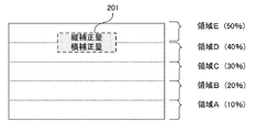
図2は、垂直方向に上方あおり投射を行った場合の例を説明するための図であり、画面内の領域毎に台形歪み補正時の縮小率が異なる状況を示している。領域A内では縮小率が10%、領域Eでは縮小率が50%というように、上底に近づくにつれて縮小率が大きくなっている。これに対して、図2の201の位置に「縦補正量」、「横補正量」といった手動調整用のOSDメニューを表示する場合を考える。「縦補正量」は領域Eに含まれ、台形歪み補正により50%の縮小が行われる。「横補正量」は領域Dに含まれ、台形歪み補正により40%の縮小が行われる。ここで領域Eに含まれるOSDメニューの表示領域がOSDメニュー内の最大縮小率であるため、OSDメニュー生成部102は、1/(1−0.5)=2倍で拡大を行い、その結果をOSDメニュー104として出力する。ここでは説明の簡易化のため、画像を5つの領域に区切った形で示しているが、実際はさらに細粒度で縮小率が定義される。また、図2の例においては、OSDメニュー生成部102は、OSDメニューの表示枠線に関して線幅を2倍の太さに拡大し、OSDメニューを生成する。
FIG. 2 is a diagram for explaining an example in the case where the upward tilting projection is performed in the vertical direction, and shows a situation in which the reduction rate at the time of correcting the trapezoidal distortion is different for each region in the screen. In the area A, the reduction ratio is 10%, and in the area E, the reduction ratio is 50%. The reduction ratio increases as it approaches the upper base. On the other hand, consider a case where an OSD menu for manual adjustment such as “vertical correction amount” and “horizontal correction amount” is displayed at a
台形歪み補正においては、投影装置100とスクリーン間のあおり角に従って、縮小率を定義する変形パラメータが変化する。あおり角が0度の場合、つまり投影装置100とスクリーンが正対している場合には、台形歪み補正の必要がなく縮小率は0%である。あおり角が小さい場合、台形歪みが小さくなり、台形歪み補正の縮小率が小さくなる。これ対してあおり角が大きい場合、台形歪みが大きくなるため、台形歪み補正の縮小率が大きくなる。台形歪み補正による縮小率が大きくなるに従って、OSDメニューに対する拡大率が大きくなり、結果としてサイズが大きいOSDメニューが生成される。よって、スクリーン上に投影される画像に対するOSDメニューのサイズが大きくなる。例えば使用者の操作により、台形歪み補正の補正量を大きくする方向に変化させると、スクリーン上に占めるOSDメニューの割合が大きくなる。逆に台形歪み補正の補正量を小さくする方向に変化させると、スクリーン上に占めるOSDメニューの割合が小さくなる。
In the trapezoidal distortion correction, the deformation parameter that defines the reduction ratio changes according to the tilt angle between the
図3は、あおり角と表示されるOSDメニューとの関係を説明するための図である。図3(a)は、投影装置100とスクリーンとが正対している場合を示している。これに対して、図3(b)は、スクリーンに対する投影装置100のあおり角が小さい場合を示しており、図3(a)に対してOSDメニューのサイズが大きく、且つ、オブジェクトである文字が大きく、線幅が太く表示される。図3(c)は、スクリーンに対する投影装置100のあおり角が大きい場合を示しており、さらにOSDメニューのサイズが大きく、且つ、オブジェクトである文字が大きく、線幅が太く表示される。なお、OSDメニューに含まれる文字や線等のオブジェクトについては、大きさや太さだけではなく、形状を変形するようにしてもよい。
FIG. 3 is a diagram for explaining the relationship between the tilt angle and the displayed OSD menu. FIG. 3A shows a case where the
このように、OSDメニューの表示領域における縮小率の逆数分を拡大することで、台形歪み補正の縮小時の間引き分を事前に補うことにより、OSDメニューの表示領域内において本来表示すべき内容の情報欠落を抑えることが可能となる。 As described above, by expanding the reciprocal of the reduction ratio in the display area of the OSD menu to compensate in advance the thinning-out amount at the time of reduction of the trapezoidal distortion correction, information on the contents that should be originally displayed in the display area of the OSD menu It is possible to suppress omissions.
本実施形態では、OSDメニューの表示領域内の縮小率の最大値で一様に拡大処理を行う主旨で説明しているが、別の実現方法としてOSDメニューの表示領域内の各縮小率の逆数でOSDメニューを拡大することも可能である。即ち、図2の例では、領域Eに含まれるOSDメニューの表示領域に対しては、OSDメニュー生成部102は1/(1−0.5)=2倍で拡大を行うことになる。また、領域Dに含まれるOSDメニューの表示領域に対しては、OSDメニュー生成部102は、1/(1−0.4)=1.67倍の拡大処理を行うことになる。
The present embodiment has been described with the main purpose of performing the enlargement process uniformly with the maximum value of the reduction ratio in the display area of the OSD menu, but as another implementation method, the reciprocal of each reduction ratio in the display area of the OSD menu. It is also possible to enlarge the OSD menu with. In other words, in the example of FIG. 2, the OSD
次に、本発明の第2の実施形態について説明する。第2の実施形態では、図4に示すOSDメニューを表示する場合について説明する。ここでは、図4に示すように、「設定A」、「設定B」、「設定C」のうち、選択された設定を大きく表示するOSDメニューを例に挙げて説明する。本実施形態は、OSDメニュー生成部102が第1の実施形態と異なる動作を行う構成であることを除き、第1の実施形態と同一構成で実現される。本実施形態におけるOSDメニュー生成部102は、「設定A」、「設定B」、「設定C」のうち、選択された設定を大きく表示するようにOSDメニューを生成する。即ち、図4(a)は「設定A」が選択された状態を示しており、図4(b)は「設定B」が選択された状態を示しており、図4(c)は「設定C」が選択された状態を示している。また、OSDメニュー生成部102には、第1の実施形態と同様、縮小率を定義した変形パラメータが入力される。以下、図4(b)のOSDメニューが表示される場合を例に挙げて、本実施形態の動作について説明する。
Next, a second embodiment of the present invention will be described. In the second embodiment, a case where the OSD menu shown in FIG. 4 is displayed will be described. Here, as shown in FIG. 4, an OSD menu that displays the selected setting among “Setting A”, “Setting B”, and “Setting C” will be described as an example. The present embodiment is realized with the same configuration as that of the first embodiment, except that the OSD
図5は、台形歪み補正における縮小率が0%、20%、40%である場合において生成されるOSDメニューを示す図である。即ち、図5(a)は、あおり角が0度であり、スクリーンと投影装置100とが正対している場合に生成されるOSDメニューを示している。図5(b)は、あおり角が小さく、縮小率が20%に設定された場合に生成されるOSDメニューを示している。図5(c)は、あおり角が大きく、縮小率が40%に設定された場に生成されるOSDメニューを示している。
FIG. 5 is a diagram showing an OSD menu generated when the reduction rate in the trapezoidal distortion correction is 0%, 20%, and 40%. That is, FIG. 5A shows an OSD menu generated when the tilt angle is 0 degree and the screen and the
OSDメニュー生成部102は、選択中を示す「設定B」のオブジェクトの生成時に、縮小率に応じて「設定B」のオブジェクトのサイズを決定する。あおり角が0度でスクリーンと投影装置100とが正対している場合、OSDメニュー生成部102は、事前に定義されたサイズで「設定B」のオブジェクトを生成する。スクリーンに対して投影装置100が傾き、「設定B」が表示される画面内の位置における縮小率の最大値が20%である場合、OSDメニュー生成部102は、1.25倍に拡大した「設定B」のオブジェクトを生成する。「設定B」のオブジェクトは、「設定B」という文字オブジェクトと枠線のオブジェクトとより構成される。「設定B」という文字オブジェクトは1.25倍のサイズに拡大され、枠線の線幅も1.25倍に拡大される。さらにあおり角を大きくし、「設定B」が表示される画面内の位置における縮小率の最大値が40%に変化した場合、OSDメニュー生成部102は、1.67倍に拡大した「設定B」のオブジェクトを生成する。このとき、「設定B」という文字オブジェクトは1.67倍のサイズに拡大され、枠線の線幅も1.67倍に拡大される。なお、「設定B」という文字オブジェクトはサイズだけではなく、太字フォントに変更することも可能である。
The OSD
次に、本発明の第3の実施形態について説明する。第3の実施形態に係る投影装置の構成は、図1に示した第1の実施形態に係る投影装置100の構成と同様である。但し、OSDメニュー生成部102の処理は第1の実施形態と異なるため、以下では、その相違点に主眼を置いて説明を行うものとする。
Next, a third embodiment of the present invention will be described. The configuration of the projection apparatus according to the third embodiment is the same as the configuration of the
OSDメニュー生成部102は、ベクター等のグラフィックスコマンドに基づいてOSDメニュー104をラスタライズする。OSDメニュー生成部102は、歪み補正量算出部105で算出された変形パラメータ110から、OSDメニューの表示位置における台形歪み補正の縮小率を抽出する。即ち、OSDメニュー生成部102内に含まれるラスタライザは、グラフィックスコマンドとOSDメニューの表示位置における台形歪み補正の縮小率とを入力し、動作する。また、上記ラスタライザは、グラフィックスコマンド内に描画指示として記述されるオブジェクトについて、表示位置の縮小率に基づきオブジェクトのサイズや太さを決定し、OSDメニューを描画する。例えば文字オブジェクトに関しては、ラスタライザは、変形パラメータに基づいてフォントのサイズを決定して描画する。線等の図形オブジェクトに関しては、ラスタライザは、画素毎の線幅を決定して描画する。このようにして生成されたOSDメニュー104に関しては、第1の実施形態と同様の処理が行われる。
The OSD
次に、本発明の第4の実施形態について説明する。図6は、第4の実施形態に係る投影装置600の構成を示す図である。図6に示すように、第4の実施形態に係る投影装置600は、図1に示す第1の実施形態に係る投影装置100の各構成の配置を変更したものである。即ち、第4の実施形態においては、OSDメニュー生成部102は、歪み補正量算出部105から変形パラメータを入力し、台形歪み補正を施したOSDメニューを生成する。また、台形歪み補正部108は、歪み補正量算出部105から変形パラメータを入力し、台形歪み補正を施した画像データを生成する。映像合成部107は、台形歪み補正後のOSDメニューと台形歪み補正後のOSDメニューとを合成し、出力する。
Next, a fourth embodiment of the present invention will be described. FIG. 6 is a diagram showing a configuration of a
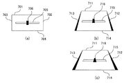
以下では、図7(a)に示すスライダーバーを含むOSDメニューをスクリーン上に生成する場合を例に挙げて、第4の実施形態について説明する。また、説明の簡素化のため、図8に示すように、台形歪み補正の条件として、垂直方向の補正のみを行うものとし、水平方向ではスクリーンと投影装置600とが正対しているものとする。図7(a)のOSDメニューは、複数のオブジェクトのパーツの組み合わせで表現される。OSDメニューの枠は、2本の縦線702、703のオブジェクトのパーツと2本の横線701、704のオブジェクトのパーツとで構成される。スライダーバーに関しては、横線705のオブジェクトのパーツと選択ポイントを示す長方形706のオブジェクトのパーツとで構成される。OSDメニュー生成時に台形歪み補正を加える場合、各部の縮小率に従って各オブジェクトのパーツの形状を変化させる。枠の縦線702、703のオブジェクトのパーツに関しては、垂直方向で縮小率が異なるため、図7(b)に示すように、縦線は細長い三角形712、713として描画される。また、枠の横線701、704に関しては、それぞれ表示位置での縮小率が異なるため、太さの異なる線711、714として描画される。またスライダーバーの線705や選択ポイントの長方形706は、それぞれ台形形状715、716として描画される。また、さらにあおり角を大きくした場合には、図7(c)に示すように三角形の形状や線幅を太く描画する。
Hereinafter, the fourth embodiment will be described by taking as an example a case where an OSD menu including the slider bar shown in FIG. 7A is generated on the screen. Further, for simplification of description, as shown in FIG. 8, it is assumed that only the correction in the vertical direction is performed as the trapezoidal distortion correction condition, and the screen and the
このようにあおり角による台形歪み補正の変形パラメータに応じてOSDメニューを描画することで、歪みの影響による視認性を改善したOSDメニューの表示が可能となる。 Thus, by drawing the OSD menu according to the deformation parameter for correcting the trapezoidal distortion by the tilt angle, it is possible to display the OSD menu with improved visibility due to the influence of distortion.
また、本発明は、以下の処理を実行することによっても実現される。即ち、上述した実施形態の機能を実現するソフトウェア(プログラム)を、ネットワーク又は各種記憶媒体を介してシステム或いは装置に供給し、そのシステム或いは装置のコンピュータ(またはCPUやMPU等)がプログラムを読み出して実行する処理である。 The present invention can also be realized by executing the following processing. That is, software (program) that realizes the functions of the above-described embodiments is supplied to a system or apparatus via a network or various storage media, and a computer (or CPU, MPU, or the like) of the system or apparatus reads the program. It is a process to be executed.
100、600:投影装置、101:映像入力部、102:OSDメニュー生成部、103:UI操作指示部、104:OSDメニュー、105:歪み補正量算出部、106:歪み検出部、107:変形パラメータ、108:台形歪み補正部、109:映像出力部、110:画像データ、111:合成画像データ 100, 600: Projection device, 101: Video input unit, 102: OSD menu generation unit, 103: UI operation instruction unit, 104: OSD menu, 105: Distortion correction amount calculation unit, 106: Distortion detection unit, 107: Deformation parameter 108: Trapezoidal distortion correction unit 109: Video output unit 110: Image data 111: Composite image data
Claims (9)
前記投影装置による投影領域のうち、ユーザインタフェース画像の投影領域が前記歪み補正により縮小する場合における前記ユーザインタフェース画像の投影領域に対応する座標値の補正量を特定する特定手段と、
前記特定手段により特定された補正量が第1の補正量である場合、前記特定手段により特定された補正量が前記第1の補正量よりも小さい第2の補正量である場合よりも、大きなユーザインタフェース画像を生成する生成手段と、
前記画像と前記生成手段により生成された前記ユーザインタフェース画像とに対して歪み補正を実行する補正手段と
を有することを特徴とする投影装置。 A projection apparatus that performs image distortion correction according to a projection direction with respect to a projection plane ,
A specifying unit that specifies a correction amount of a coordinate value corresponding to the projection area of the user interface image when a projection area of the user interface image is reduced by the distortion correction among the projection areas of the projection device;
When the correction amount specified by the specifying unit is the first correction amount, it is larger than when the correction amount specified by the specifying unit is a second correction amount that is smaller than the first correction amount. Generating means for generating a user interface image;
A projection apparatus comprising: correction means for performing distortion correction on the image and the user interface image generated by the generation means.
前記生成手段は、対応する補正量に基づいた大きさで前記生成手段により生成された前記複数のユーザインタフェース画像のうち、ユーザに選択されたユーザインタフェース画像を前記判定手段の判定に応じて拡大することを特徴とする請求項1乃至3のうち何れか1項に記載の投影装置。 A determination unit for determining a user interface image selected by the user among the plurality of user interface images;
The generation unit enlarges a user interface image selected by a user among the plurality of user interface images generated by the generation unit with a size based on a corresponding correction amount according to the determination of the determination unit. The projection apparatus according to claim 1, wherein the projection apparatus is characterized in that:
前記投影装置による投影領域のうち、ユーザインタフェース画像の投影領域が前記歪み補正により縮小する場合における前記ユーザインタフェース画像の投影領域に対応する座標値の補正量を特定する特定工程と、A specifying step of specifying a correction amount of a coordinate value corresponding to the projection area of the user interface image when the projection area of the user interface image is reduced by the distortion correction among the projection areas by the projection device;
前記特定工程により特定された補正量が第1の補正量である場合、前記特定工程により特定された補正量が前記第1の補正量よりも小さい第2の補正量である場合よりも、大きなユーザインタフェース画像を生成する生成工程と、When the correction amount specified by the specifying step is the first correction amount, it is larger than when the correction amount specified by the specifying step is a second correction amount that is smaller than the first correction amount. A generation step of generating a user interface image;
前記画像と前記生成工程により生成された前記ユーザインタフェース画像とに対して歪み補正を実行する補正工程とを有することを特徴とする制御方法。A control method comprising: a correction step of performing distortion correction on the image and the user interface image generated by the generation step.
前記生成工程は、対応する補正量に基づいた大きさで前記生成工程により生成された前記複数のユーザインタフェース画像のうち、ユーザに選択されたユーザインタフェース画像を前記判定工程の判定に応じて拡大することを特徴とする請求項5乃至7のうち何れか1項に記載の制御方法。 A determination step of determining a user interface image selected by the user among the plurality of user interface images;
The generation step enlarges a user interface image selected by a user among the plurality of user interface images generated by the generation step with a size based on a corresponding correction amount according to the determination in the determination step. The control method according to any one of claims 5 to 7, wherein:
Priority Applications (3)
| Application Number | Priority Date | Filing Date | Title |
|---|---|---|---|
| JP2011084720A JP5832119B2 (en) | 2011-04-06 | 2011-04-06 | Projection apparatus, control method thereof, and program |
| EP12161043.0A EP2509321B1 (en) | 2011-04-06 | 2012-03-23 | Projection apparatus, control method thereof, and program |
| US13/436,142 US20120257173A1 (en) | 2011-04-06 | 2012-03-30 | Projection apparatus, control method thereof, and program- storing storage medium |
Applications Claiming Priority (1)
| Application Number | Priority Date | Filing Date | Title |
|---|---|---|---|
| JP2011084720A JP5832119B2 (en) | 2011-04-06 | 2011-04-06 | Projection apparatus, control method thereof, and program |
Publications (3)
| Publication Number | Publication Date |
|---|---|
| JP2012222517A JP2012222517A (en) | 2012-11-12 |
| JP2012222517A5 JP2012222517A5 (en) | 2014-05-22 |
| JP5832119B2 true JP5832119B2 (en) | 2015-12-16 |
Family
ID=45855585
Family Applications (1)
| Application Number | Title | Priority Date | Filing Date |
|---|---|---|---|
| JP2011084720A Active JP5832119B2 (en) | 2011-04-06 | 2011-04-06 | Projection apparatus, control method thereof, and program |
Country Status (3)
| Country | Link |
|---|---|
| US (1) | US20120257173A1 (en) |
| EP (1) | EP2509321B1 (en) |
| JP (1) | JP5832119B2 (en) |
Families Citing this family (5)
| Publication number | Priority date | Publication date | Assignee | Title |
|---|---|---|---|---|
| JP5997882B2 (en) * | 2011-07-21 | 2016-09-28 | セイコーエプソン株式会社 | Projector and projector control method |
| JP6263881B2 (en) * | 2013-07-10 | 2018-01-24 | 株式会社リコー | Image projection apparatus, control method for image projection apparatus, and control program for image projection apparatus |
| JP6897191B2 (en) * | 2017-03-17 | 2021-06-30 | セイコーエプソン株式会社 | Projector and projector control method |
| JP7415439B2 (en) | 2019-10-28 | 2024-01-17 | セイコーエプソン株式会社 | Projector control method and projector |
| CN112689134B (en) * | 2020-12-21 | 2022-08-16 | 苏州长风航空电子有限公司 | Information display terminal with trapezoidal correction for airborne cargo compartment |
Family Cites Families (27)
| Publication number | Priority date | Publication date | Assignee | Title |
|---|---|---|---|---|
| JPH10111533A (en) * | 1996-10-03 | 1998-04-28 | Seiko Epson Corp | Projection display device |
| JPH1173290A (en) * | 1997-07-03 | 1999-03-16 | Funai Electric Co Ltd | Menu display device |
| JP4252671B2 (en) * | 1999-05-21 | 2009-04-08 | セイコーエプソン株式会社 | Projection display |
| DE69930152T2 (en) * | 1999-12-24 | 2006-08-10 | Matsushita Electric Industrial Co., Ltd., Kadoma | PROJECTOR |
| JP3646658B2 (en) * | 2001-03-01 | 2005-05-11 | セイコーエプソン株式会社 | Image distortion correction |
| JP2003153135A (en) * | 2001-11-16 | 2003-05-23 | Sanyo Electric Co Ltd | Projection display device |
| CN100460993C (en) * | 2003-07-17 | 2009-02-11 | 三洋电机株式会社 | Projection type video display |
| CN100403157C (en) * | 2003-07-17 | 2008-07-16 | 三洋电机株式会社 | Projection type image display device and factory - adjusted control method of the same display device |
| JP3827662B2 (en) * | 2003-09-10 | 2006-09-27 | Necビューテクノロジー株式会社 | Projection display |
| JP3960972B2 (en) * | 2004-01-16 | 2007-08-15 | 三洋電機株式会社 | Projection display device |
| JP2005210418A (en) * | 2004-01-22 | 2005-08-04 | Sanyo Electric Co Ltd | Image processing device, method, and program |
| JP2006191387A (en) * | 2005-01-06 | 2006-07-20 | Nec Saitama Ltd | Portable telephone set with camera function |
| US20090115915A1 (en) * | 2006-08-09 | 2009-05-07 | Fotonation Vision Limited | Camera Based Feedback Loop Calibration of a Projection Device |
| JP2008217540A (en) * | 2007-03-06 | 2008-09-18 | Funai Electric Co Ltd | Image information reproducer and hdd recorder |
| JP2009177581A (en) * | 2008-01-25 | 2009-08-06 | Necディスプレイソリューションズ株式会社 | Projection type display device and caption display method |
| JP5577023B2 (en) * | 2008-02-22 | 2014-08-20 | 日立コンシューマエレクトロニクス株式会社 | Display device |
| JP2009216815A (en) * | 2008-03-07 | 2009-09-24 | Sanyo Electric Co Ltd | Projection type video display device |
| JP5405047B2 (en) * | 2008-05-09 | 2014-02-05 | 三洋電機株式会社 | Projection display device |
| US8159760B2 (en) * | 2008-08-19 | 2012-04-17 | Seiko Epson Corporation | Projector and control method of projector |
| JP2010054550A (en) * | 2008-08-26 | 2010-03-11 | Seiko Epson Corp | Image display device, projector, program, and information storage medium |
| JP2010152267A (en) * | 2008-12-26 | 2010-07-08 | Seiko Epson Corp | Projector |
| JP2010164879A (en) * | 2009-01-19 | 2010-07-29 | Panasonic Corp | Display device |
| JP2011066738A (en) * | 2009-09-18 | 2011-03-31 | Sanyo Electric Co Ltd | Projection type video display device |
| JP2011065025A (en) * | 2009-09-18 | 2011-03-31 | Sanyo Electric Co Ltd | Projection type image display device |
| JP5442393B2 (en) * | 2009-10-29 | 2014-03-12 | 日立コンシューマエレクトロニクス株式会社 | Display device |
| JP5441672B2 (en) * | 2009-12-25 | 2014-03-12 | キヤノン株式会社 | Projection display |
| US20130335643A1 (en) * | 2011-03-04 | 2013-12-19 | Kenji Ishida | Projection-type image display device and light quantity adjustment method |
-
2011
- 2011-04-06 JP JP2011084720A patent/JP5832119B2/en active Active
-
2012
- 2012-03-23 EP EP12161043.0A patent/EP2509321B1/en active Active
- 2012-03-30 US US13/436,142 patent/US20120257173A1/en not_active Abandoned
Also Published As
| Publication number | Publication date |
|---|---|
| EP2509321B1 (en) | 2017-05-10 |
| EP2509321A2 (en) | 2012-10-10 |
| US20120257173A1 (en) | 2012-10-11 |
| EP2509321A3 (en) | 2012-11-21 |
| JP2012222517A (en) | 2012-11-12 |
Similar Documents
| Publication | Publication Date | Title |
|---|---|---|
| US8423903B2 (en) | Aspect ratio hinting for resizable video windows | |
| JP4770878B2 (en) | Information display device and program | |
| US20150091939A1 (en) | Display device, computer program, and computer-implemented method | |
| JP5832119B2 (en) | Projection apparatus, control method thereof, and program | |
| US9275486B2 (en) | Collage image creating method and collage image creating device | |
| JP5870586B2 (en) | Projector control device, display device, and program. | |
| WO2018198703A1 (en) | Display device | |
| JP5907196B2 (en) | Image processing apparatus, image processing method, image processing system, and program | |
| JP5299125B2 (en) | Document processing apparatus and program | |
| US20130169671A1 (en) | Projector and method for controlling image display of the same | |
| JP6145738B2 (en) | Display device and computer program | |
| JP5023937B2 (en) | Image processing apparatus, image processing system, and program | |
| JP2018054763A (en) | Image projection device, method for controlling image projection device, and program | |
| CN110363832B (en) | Subtitle generating method and device | |
| JP2006195512A (en) | Display control device and display control program | |
| JP6614516B2 (en) | Display device and computer program | |
| JP2005084089A (en) | Image comparison display method and its device, and image comparison display program | |
| JP4851860B2 (en) | Projector and angle of view control method | |
| JP6285657B2 (en) | Image processing apparatus, image processing method, and program | |
| US11917341B2 (en) | Control method for projector and projector | |
| JP2011135350A (en) | Image processing apparatus and method of controlling the same | |
| JP2018022044A (en) | Image processing apparatus, multi-projection system, method for controlling image processing apparatus, and program | |
| JP2006227091A (en) | Display apparatus, display method, display program and recording medium | |
| KR20160115214A (en) | Display apparatus and display method thereof | |
| CN115640085A (en) | Method for processing image by computing equipment and computing equipment |
Legal Events
| Date | Code | Title | Description |
|---|---|---|---|
| A521 | Written amendment |
Free format text: JAPANESE INTERMEDIATE CODE: A523 Effective date: 20140403 |
|
| A621 | Written request for application examination |
Free format text: JAPANESE INTERMEDIATE CODE: A621 Effective date: 20140403 |
|
| A977 | Report on retrieval |
Free format text: JAPANESE INTERMEDIATE CODE: A971007 Effective date: 20150113 |
|
| A131 | Notification of reasons for refusal |
Free format text: JAPANESE INTERMEDIATE CODE: A131 Effective date: 20150120 |
|
| A521 | Written amendment |
Free format text: JAPANESE INTERMEDIATE CODE: A523 Effective date: 20150320 |
|
| TRDD | Decision of grant or rejection written | ||
| A01 | Written decision to grant a patent or to grant a registration (utility model) |
Free format text: JAPANESE INTERMEDIATE CODE: A01 Effective date: 20150929 |
|
| A61 | First payment of annual fees (during grant procedure) |
Free format text: JAPANESE INTERMEDIATE CODE: A61 Effective date: 20151027 |
|
| R151 | Written notification of patent or utility model registration |
Ref document number: 5832119 Country of ref document: JP Free format text: JAPANESE INTERMEDIATE CODE: R151 |