JP5819925B2 - Code reading device and code reading program - Google Patents
Code reading device and code reading program Download PDFInfo
- Publication number
- JP5819925B2 JP5819925B2 JP2013266474A JP2013266474A JP5819925B2 JP 5819925 B2 JP5819925 B2 JP 5819925B2 JP 2013266474 A JP2013266474 A JP 2013266474A JP 2013266474 A JP2013266474 A JP 2013266474A JP 5819925 B2 JP5819925 B2 JP 5819925B2
- Authority
- JP
- Japan
- Prior art keywords
- area
- region
- unit
- barcode
- areas
- Prior art date
- Legal status (The legal status is an assumption and is not a legal conclusion. Google has not performed a legal analysis and makes no representation as to the accuracy of the status listed.)
- Active
Links
Images


Classifications
-
- G—PHYSICS
- G06—COMPUTING; CALCULATING OR COUNTING
- G06K—GRAPHICAL DATA READING; PRESENTATION OF DATA; RECORD CARRIERS; HANDLING RECORD CARRIERS
- G06K7/00—Methods or arrangements for sensing record carriers, e.g. for reading patterns
- G06K7/10—Methods or arrangements for sensing record carriers, e.g. for reading patterns by electromagnetic radiation, e.g. optical sensing; by corpuscular radiation
- G06K7/14—Methods or arrangements for sensing record carriers, e.g. for reading patterns by electromagnetic radiation, e.g. optical sensing; by corpuscular radiation using light without selection of wavelength, e.g. sensing reflected white light
- G06K7/1404—Methods for optical code recognition
- G06K7/146—Methods for optical code recognition the method including quality enhancement steps
- G06K7/1491—Methods for optical code recognition the method including quality enhancement steps the method including a reconstruction step, e.g. stitching two pieces of bar code together to derive the full bar code
-
- G—PHYSICS
- G06—COMPUTING; CALCULATING OR COUNTING
- G06K—GRAPHICAL DATA READING; PRESENTATION OF DATA; RECORD CARRIERS; HANDLING RECORD CARRIERS
- G06K19/00—Record carriers for use with machines and with at least a part designed to carry digital markings
- G06K19/06—Record carriers for use with machines and with at least a part designed to carry digital markings characterised by the kind of the digital marking, e.g. shape, nature, code
- G06K19/06009—Record carriers for use with machines and with at least a part designed to carry digital markings characterised by the kind of the digital marking, e.g. shape, nature, code with optically detectable marking
- G06K19/06018—Record carriers for use with machines and with at least a part designed to carry digital markings characterised by the kind of the digital marking, e.g. shape, nature, code with optically detectable marking one-dimensional coding
- G06K19/06028—Record carriers for use with machines and with at least a part designed to carry digital markings characterised by the kind of the digital marking, e.g. shape, nature, code with optically detectable marking one-dimensional coding using bar codes
-
- G—PHYSICS
- G06—COMPUTING; CALCULATING OR COUNTING
- G06K—GRAPHICAL DATA READING; PRESENTATION OF DATA; RECORD CARRIERS; HANDLING RECORD CARRIERS
- G06K7/00—Methods or arrangements for sensing record carriers, e.g. for reading patterns
- G06K7/10—Methods or arrangements for sensing record carriers, e.g. for reading patterns by electromagnetic radiation, e.g. optical sensing; by corpuscular radiation
- G06K7/14—Methods or arrangements for sensing record carriers, e.g. for reading patterns by electromagnetic radiation, e.g. optical sensing; by corpuscular radiation using light without selection of wavelength, e.g. sensing reflected white light
- G06K7/1404—Methods for optical code recognition
- G06K7/1439—Methods for optical code recognition including a method step for retrieval of the optical code
- G06K7/1447—Methods for optical code recognition including a method step for retrieval of the optical code extracting optical codes from image or text carrying said optical code
Landscapes
- Engineering & Computer Science (AREA)
- Physics & Mathematics (AREA)
- General Physics & Mathematics (AREA)
- Theoretical Computer Science (AREA)
- Health & Medical Sciences (AREA)
- Electromagnetism (AREA)
- General Health & Medical Sciences (AREA)
- Toxicology (AREA)
- Artificial Intelligence (AREA)
- Computer Vision & Pattern Recognition (AREA)
- Quality & Reliability (AREA)
- Character Input (AREA)
Description
本発明は、コード読取装置およびコード読取用プログラムに関し、特に、撮影した画像からバーコードの読み取りを行うコード読取装置に用いて好適なものである。 The present invention relates to a code reading device and a code reading program, and is particularly suitable for use in a code reading device that reads a barcode from a photographed image.
従来、あらかじめ規定された白線と種々の太さの黒線との組み合せから成る縞模様によって各種の情報を表すバーコードや、複数のドットを縦横に配列してより多くの情報を表すことを可能にした二次元コードは、その読み取りとコード認識が容易であるため、広い分野に利用されている。 Conventionally, it is possible to express more information by arranging various dots vertically and horizontally by using a striped pattern consisting of a combination of white lines defined in advance and black lines of various thicknesses. These two-dimensional codes are used in a wide range of fields because they are easy to read and recognize.
例えば、これらのバーコードや二次元コード(以下、これらをまとめて単にコードという)は、商品のパッケージ等に付され、流通過程において商品を認識するために使われる。この場合、コードは専用のコードリーダやカメラ等によって読み取られ、数値や文字からなる情報にデコードされる。また、最近では、携帯電話やスマートフォン等のモバイル端末の画面上にコードを表示させ、これを専用のコードリーダで読み取ってデコードするようにした技術も提供されている。 For example, these bar codes and two-dimensional codes (hereinafter collectively referred to simply as codes) are attached to a product package or the like, and are used to recognize the product in the distribution process. In this case, the code is read by a dedicated code reader, a camera or the like, and decoded into information consisting of numerical values and characters. Recently, a technology has also been provided in which a code is displayed on the screen of a mobile terminal such as a mobile phone or a smartphone, and is read and decoded by a dedicated code reader.
しかしながら、商品のパッケージ等に付されたコードをカメラで読み取る場合、コード自体に汚れが付いていたり、カメラで撮影した画像のコード上に照明光が重なって写り込んでしまったりしていると、コードの正確な読み取りができなくなってしまうという問題があった。 However, when reading the code attached to the product package etc. with the camera, if the code itself is dirty, or if the illumination light overlaps the code of the image taken with the camera, There was a problem that the code could not be read accurately.
また、モバイル端末の表示画面に表示させたコードを読み取る場合、表示画面に傷や汚れがあったり、コードリーダからの照明光の入射角度によって表示画面が部分的に鏡面反射を起こしたりすると、コードの正確な読み取りができなくなってしまうという問題があった。 In addition, when reading a code displayed on the display screen of a mobile device, if the display screen is scratched or dirty, or if the display screen partially mirrors due to the incident angle of illumination light from the code reader, There was a problem that it could not be read accurately.
後者のような問題に鑑みて、モバイル端末の画面に鏡面反射が生じたり、画面に傷や汚れなどが付いていたりしても、画面に表示されたQRコードを正確にデコードすることを可能にした技術が提案されている(例えば、特許文献1参照)。この特許文献1に記載の技術では、同一のQRコードの画像を画面上に時間間隔を置いて複数回表示するようにし、かつ、その複数回表示する画像は、各回で互いに90度回転した状態に表示するようにする。このようにすれば、QRコードの一部に読み取れない箇所が生じていても、1回目のQRコードの表示で読み取り不能となった部分が2回目以降の表示で読み取り可能となる。 In view of the latter problem, it is possible to accurately decode the QR code displayed on the screen even if the screen of the mobile terminal is specularly reflected or the screen is scratched or dirty. Have been proposed (see, for example, Patent Document 1). In the technique described in Patent Document 1, an image of the same QR code is displayed on a screen a plurality of times with a time interval, and the images displayed a plurality of times are rotated 90 degrees each time. To display. In this way, even if there is a portion that cannot be read in a part of the QR code, the portion that cannot be read in the first display of the QR code can be read in the second and subsequent displays.
また、この特許文献1には、1つのQRコードを複数個に分割し、その分割された各コードの画像を画面上に時間間隔を置いて順に表示することも記載されている。この場合、分割された各コードをコードリーダで読み取ってデコードし、各コードからデコードされた複数のデータを合成することによって、元のQRコードのデコードデータとするようになされている。 Further, this Patent Document 1 also describes that one QR code is divided into a plurality of pieces and images of the divided codes are sequentially displayed on the screen at time intervals. In this case, each divided code is read and decoded by a code reader, and a plurality of pieces of data decoded from the respective codes are combined to obtain decoded data of the original QR code.
上記特許文献1に記載の技術では、モバイル端末の画面上に表示させたコードの一部が画面の汚れや鏡面反射などによって読み取れない場合の問題は解消することが可能である。しかしながら、カメラで撮影された画像内に写ったコードそのものが、商品のパッケージ等に付されたコード自体の汚れや撮影画像への照明光の写り込みなどによって読み取れない場合の問題は解消することができない。 With the technique described in Patent Document 1, it is possible to solve the problem in the case where a part of the code displayed on the screen of the mobile terminal cannot be read due to screen contamination or specular reflection. However, the problem that the code itself in the image taken with the camera cannot be read due to dirt on the code itself attached to the product package or the reflection of the illumination light on the photographed image can be solved. Can not.
本発明は、このような問題を解決するために成されたものであり、商品のパッケージ等に付されたコード自体に汚れが付いていたり、撮影画像内のコード上に照明光が重なって写り込んでしまったりしている場合でも、コードの正確な読み取りを行うことができるようにすることを目的とする。 The present invention has been made to solve such a problem, and the code itself attached to the product package or the like is soiled, or the illumination light is superimposed on the code in the photographed image. The purpose is to be able to read the code accurately even if it is intrusive.
上記した課題を解決するために、本発明では、バーコードの撮影画像を複数の水平エリアに分割し、白色のエリア幅が白線の最大幅を超えるところを区切りとして、各水平エリアの中から読み取り可能な領域をそれぞれ抽出し、抽出した複数の領域を結合することによってバーコードの全体を復元するようにしている。 In order to solve the above-described problems, in the present invention, the captured image of the barcode is divided into a plurality of horizontal areas, and is read from each horizontal area with the white area width exceeding the maximum width of the white line as a delimiter. Each possible area is extracted, and the entire barcode is restored by combining the extracted areas.
上記のように構成した本発明によれば、商品のパッケージ等に付されたコード自体に汚れが付いていたり、撮影画像内のコード上に照明光が重なって写り込んでしまったりして、バーコードの一部に読み取れない箇所が生じていても、読み取り可能な複数の領域が部分的に抽出され、それらの領域が結合されて全体として読み取り可能なバーコードが復元される。これにより、部分的に汚れや照明光の写り込みがあるバーコードであっても正確な読み取りを行うことができる。 According to the present invention configured as described above, the code itself attached to the product package or the like is soiled, or the illumination light is superimposed on the code in the photographed image, and the bar Even if a portion that cannot be read occurs in a part of the code, a plurality of readable areas are partially extracted, and these areas are combined to restore a readable barcode as a whole. As a result, accurate reading can be performed even for barcodes that are partially contaminated or have reflected illumination light.
以下、本発明の一実施形態を図面に基づいて説明する。図1は、本実施形態によるコード読取装置の機能構成例を示すブロック図である。本実施形態のコード読取装置10は、例えばスマートフォンやタブレット等のモバイル端末に実装されるものであり、その機能構成として、画像入力部1、領域抽出部2、領域選別部3、領域結合部4およびデコード部5を備えている。
Hereinafter, an embodiment of the present invention will be described with reference to the drawings. FIG. 1 is a block diagram illustrating a functional configuration example of the code reading apparatus according to the present embodiment. The
上記各機能ブロック1〜5は、ハードウェア、DSP(Digital Signal Processor)、ソフトウェアの何れによっても構成することが可能である。例えばソフトウェアによって構成する場合、上記各機能ブロック1〜5は、実際にはコンピュータのCPU、RAM、ROMなどを備えて構成され、RAMやROM、ハードディスクまたは半導体メモリ等の記録媒体に記憶されたコード読取用プログラムが動作することによって実現される。 Each of the functional blocks 1 to 5 can be configured by any of hardware, DSP (Digital Signal Processor), and software. For example, when configured by software, each of the functional blocks 1 to 5 is actually configured by including a CPU, RAM, ROM, etc. of a computer, and a code stored in a recording medium such as RAM, ROM, hard disk, or semiconductor memory. This is realized by the operation of the reading program.
画像入力部1は、モバイル端末が備えるカメラ15により撮影されたバーコードの画像を入力する。例えば、商品のパッケージに付されたバーコードをユーザがカメラ15で撮影すると、画像入力部1はその撮影画像をカメラ15からコード読取装置10に入力する。
The image input unit 1 inputs a barcode image captured by the
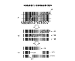
領域抽出部2は、画像入力部1により入力されたバーコードの撮影画像を複数の水平エリアに分割し、各水平エリアの中から読み取り可能な領域をそれぞれ抽出する。図2は、この領域抽出部2の動作を説明するための図である。図2(a)は、商品のパッケージに付されたバーコードの撮影画像を示すものであり、バーコード上に汚れ20が付いた状態を示している。
The
図2(b)は、汚れ20の付いたバーコードの撮影画像を3つの水平エリア21,22,23に3等分した状態を示し、図2(c)は、各水平エリア21,22,23の中から読み取り可能な領域24〜28をそれぞれ抽出した状態を示している。読み取り可能な領域24〜28とは、例えば、黒線および白線の全長において汚れ20が全く付着していない領域である。バーコードに汚れ20が付着していると、その汚れ20の部分は黒色でも白色でもない中間色となる。そこで、領域抽出部2は、黒線および白線の全長の中に中間色が含まれていないエリアを読み取り可能な領域24〜28として抽出する。
FIG. 2B shows a state where a bar code image with a
また、バーコードでは通常、白線として採り得る最大幅が規定されている。そこで、領域抽出部2は、白色のエリア幅が白線の最大幅を超えるかどうかを判定し、超える場合にはそこで領域を分断する。すなわち、真ん中の水平エリア22では領域を分断して2つの読み取り可能な領域25,26を抽出し、一番下の水平エリア23でも領域を分断して2つの読み取り可能な領域27,28を抽出する。
Further, the maximum width that can be taken as a white line is normally defined in the barcode. Therefore, the
領域選別部3は、領域抽出部2により抽出された複数の読み取り可能な領域24〜28の中から、領域結合部4による結合に適した領域を選別する。図3は、この領域選別部3の動作を説明するための図である。結合に適した領域とは、領域結合部4によって結合を行ったときに元のバーコードの全体を復元可能な最小限の領域である。
The region selection unit 3 selects a region suitable for combination by the region combination unit 4 from the plurality of
具体的には、領域選別部3は、バーコードの左端を含む第1の領域24と、バーコードの右端を含む第2の領域28とを少なくとも選別する。左端を含む領域が複数ある場合は、その中から横幅が最も長いものを選別する。すなわち、左端を含む3つの読み取り可能な領域24,25,27の中から、横幅が最も長い領域24を選別する。同様に、右端を含む領域が複数ある場合は、その中から横幅が最も長いものを選別する。すなわち、右端を含む2つの読み取り可能な領域26,28の中から、横幅が最も長い領域28を選別する。
Specifically, the area sorting unit 3 sorts at least the
領域選別部3は、以上のようにして抽出した第1の領域24と第2の領域28とに重複領域が存在するか否かを判定する。重複領域が存在する場合、領域選別部3はそれ以外に領域の選別を行わない。図3の場合はこれに該当するので、領域選別部3が選別する領域は第1の領域24および第2の領域28のみである。
The area selection unit 3 determines whether or not there is an overlapping area between the
一方、図4に示すように、バーコードの左端を含む第1の領域31と右端を含む第2の領域32とに重複領域が存在しない場合、領域選別部3は、第1の領域と31第2の領域32との間を繋ぐ中間の位置にある1以上の第3の領域33をさらに選別する。このとき選別する第3の領域33は、図4(a)に示すように、第1の領域31との間に重複領域を有し、かつ、第2の領域32との間にも重複領域を有する領域であるのが好ましい。選別する第3の領域33が最小限の1個で済むからである。
On the other hand, as shown in FIG. 4, when there is no overlapping region in the
ただし、第1の領域31と第2の領域32との両方に重複する領域が存在しない場合は、図4(b)に示すように、少なくとも第1の領域31との間で重複領域を有する第3の領域33-1と、少なくとも第2の領域32との間で重複領域を有する第3の領域33-2とを選別する。なお、このように第3の領域33を複数選別できるようにするには、水平エリアの分割数を4つ以上とする必要がある。
However, when there is no overlapping region in both the
図4(b)のように選別する2つの第3の領域33-1,33-2は、互いが重複する領域を持つものであるのが好ましい。選別する第3の領域33-1,33-2が2個で済むからである。なお、2つの第3の領域33-1,33-2との間にも重複領域が存在しない場合、領域選別部3はその間を繋ぐ中間の位置にある別の第3の領域をさらに選別する。
As shown in FIG. 4B, the two
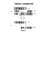
領域結合部4は、領域選別部3により選別された領域を結合することにより、バーコードの全体を復元する。具体的には、領域結合部4は、複数の領域の位置をずらしながら領域内の線分を結合させていき、複数の領域内の線分の合致度が最も高い位置の結合状態を採用する。 The region combining unit 4 restores the entire barcode by combining the regions selected by the region selecting unit 3. Specifically, the region combining unit 4 combines the line segments in the regions while shifting the positions of the plurality of regions, and adopts the combined state at the position where the degree of matching of the line segments in the plurality of regions is the highest. .
図5は、この領域結合部4の動作を説明するための図である。図5(a)〜(c)は、領域選別部3により選別された第1の領域24と第2の領域28との位置関係を1ドットずつ水平方向にずらしていったときの3つの状態を代表として示している。このうち、図5(b)が、第1の領域24内にある黒線と第2の領域28内にある黒線との合致度が最も高い状態を示している。
FIG. 5 is a diagram for explaining the operation of the region coupling unit 4. 5A to 5C show three states when the positional relationship between the
この場合、領域結合部4は、図5(b)の位置関係にあるときの結合状態を採用し、第1の領域24内にある黒線と第2の領域28内にある黒線とを結合させる。具体的には、合致している線分(重複領域の線分)どうしが1つに重ね合されるように、第1の領域24の画像と第2の領域28の画像とを合成する。その結果を示したものが図5(d)である。
In this case, the region coupling unit 4 adopts the coupling state when the positional relationship of FIG. 5B is used, and the black line in the
なお、図4のように3つ以上の領域が選別されている場合は、互いに重複領域を有する2つの領域間で上述の処理を行うことによって、バーコードの全体を復元する。例えば、図4(a)のように3つの領域31〜33が選別されている場合は、第1の領域31と第3の領域33との間で線分の結合を行うとともに、第2の領域32と第3の領域33との間で線分の結合を行う。
When three or more areas are selected as shown in FIG. 4, the entire barcode is restored by performing the above-described processing between two areas having overlapping areas. For example, when three
デコード部5は、領域結合部4により復元されたバーコードをデコードし、それによって得られた数値列や文字列などの情報を出力する。図5(d)に示したように、領域結合部4により復元されたバーコードは、垂直方向の長さ(黒線と白線の長さ)が本来のバーコードよりも短くなっている。ただし、水平方向の縞模様は完全に復元されている。バーコードの読み取りは水平方向の縞模様に基づき行われるので、図5(d)のように垂直方向の長さが短くなっていても、正しくデコードを行うことが可能である。 The decoding unit 5 decodes the barcode restored by the region combining unit 4 and outputs information such as a numeric string and a character string obtained thereby. As shown in FIG. 5D, the barcode restored by the region combination unit 4 has a shorter vertical length (the length of the black and white lines) than the original barcode. However, the horizontal stripe pattern is completely restored. Since the barcode is read based on the horizontal stripe pattern, the barcode can be correctly decoded even if the length in the vertical direction is shortened as shown in FIG.
以上詳しく説明したように、本実施形態では、バーコードの撮影画像を複数の水平エリア21〜23に分割し、各水平エリア21〜23の中から読み取り可能な領域24〜28をそれぞれ抽出し、さらに結合に適した領域24,28を選別する。そして、選別した領域22,28を結合することによってバーコードの全体を復元するようにしている。
As described above in detail, in the present embodiment, the captured image of the barcode is divided into a plurality of
このように構成した本実施形態によれば、図2(a)のように商品のパッケージ等に付されたバーコード自体に汚れ20が付いていて、バーコードの一部に読み取れない箇所が生じていても、図5(d)のように全体として読み取り可能なバーコードの画像を生成することができる。これにより、部分的に汚れ20があるバーコードであっても、正確な読み取りを行うことができる。同様に、撮影画像内のバーコード上に照明光が重なって写り込んでしまっていても、正確な読み取りを行うことができる。
According to the present embodiment configured as described above, as shown in FIG. 2 (a), the barcode itself attached to the product package or the like has
なお、上記実施形態では、複数の読み取り可能な領域24〜28の中から結合に適した領域24,28を選別し、当該選別した領域24,28を結合する例について説明したが、本発明はこれに限定されない。例えば、領域抽出部2により抽出された複数の領域24〜28を結合することによってバーコードの全体を復元するようにしてもよい。ただし、結合させる領域の選別を行った方が結合の際の処理負荷を減らすことができる点で好ましい。
In the above-described embodiment, the example in which the
また、上記実施形態では、バーコードを3つの水平エリア21〜23に3等分する例について説明したが、この分割数は単なる例示に過ぎない。分割数を多くした方が、領域結合部4による結合に適した領域が長くなりやすいので、3つより多い水平エリアに分割するようにしてもよい。 Moreover, although the said embodiment demonstrated the example which divides a barcode into three horizontal areas 21-23 equally, this division number is only a mere illustration. When the number of divisions is increased, a region suitable for combining by the region combining unit 4 tends to be long. Therefore, the region may be divided into more than three horizontal areas.
また、最初は2つの水平エリアに分割し、それぞれの水平エリア内から領域選別部3により選別される領域が2つ以下とならない場合に、分割数を3つに増やすようにしてもよい。そして、3つの水平エリア内から領域選別部3により選別される領域が2つ以下とならない場合には、分割数をさらに4つに増やすというように、領域選別部3により選別される領域が2つ以下となるまで水平エリアの分割数を増やしていくようにしてもよい。 Alternatively, it may be initially divided into two horizontal areas, and the number of divisions may be increased to three when the number of areas selected by the area selection unit 3 from each horizontal area is not less than two. Then, if the number of areas selected by the area selecting unit 3 from the three horizontal areas is not less than two, the number of areas selected by the area selecting unit 3 is 2 so that the number of divisions is further increased to four. You may make it increase the division | segmentation number of a horizontal area until it becomes less than one.
このようにすれば、領域結合部4では常に2つ以下の領域を結合すれば良くなるので(領域選別部3により選別される領域が1つのみの場合は結合自体が不要となる)、結合の際の処理負荷を減らすことができる。なお、水平エリアの分割数を増やすか否かの判断基準は、領域選別部3により選別される領域が3つ以下となるか否かとしてもよい。 In this way, the region combining unit 4 always has to combine two or less regions (when only one region is selected by the region selecting unit 3, the connection itself is not necessary). Can reduce the processing load. Note that the criterion for determining whether or not to increase the number of divisions in the horizontal area may be whether or not the number of areas selected by the area selection unit 3 is three or less.
また、最初は2つの水平エリアに分割し、それぞれの水平エリアから領域抽出部2により抽出される読み取り可能な領域の何れにおいてもバーコードの左端または右端が含まれていない場合に、分割数を3つに増やすようにしてもよい。そして、水平エリアの分割数を3つに増やしても、バーコードの左端を含む領域または右端を含む領域が領域抽出部2により抽出されない場合には、分割数をさらに4つに増やすというように、バーコードの左端を含む領域と右端を含む領域との両方が領域抽出部2により抽出されるまで水平エリアの分割数を増やしていくようにしてもよい。
In addition, when the area is divided into two horizontal areas at first, and the left end or the right end of the barcode is not included in any of the readable areas extracted by the
また、上記実施形態では、領域抽出部2は、黒線および白線の全長において中間色が全く含まれていないエリアを読み取り可能な領域24〜28として抽出する例について説明したが、本発明はこれに限定されない。例えば、全長の中の一部に汚れ20が付いていても、黒線の少なくとも一部が汚れ20のない状態となっているエリアも含めて読み取り可能な領域を抽出するようにしてもよい。ただし、この場合は、読み取り可能な領域を抽出した後、汚れ20を除去する処理を行う。
In the above-described embodiment, the
汚れ20を除去する処理は、例えば以下のようにして行うことが可能である。すなわち、中間色のある領域を水平方向1ドットずつ垂直方向(黒線または白線の長さ方向)にスキャンして、列内に黒色または白色のどちらのドットが含まれているかを判断することにより、黒線または白線のどちらに汚れ20が付いているのかを列ごとに判別する。そして、黒線に汚れ20が付いている列については汚れ20の中間色を黒色に置換する。一方、白線に汚れ20が付いている列については汚れ20の中間色を白色に置換する。
The process of removing the
このようにすれば、領域抽出部2により抽出される読み取り可能な領域の水平方向の長さがより長くなり、領域選別部3により選別される領域の数をできるだけ少なくすることができる可能性が高くなる。これにより、領域結合部4によって線分の結合を行う際の処理負荷を減らすことができる。また、領域抽出部2が読み取り可能な領域を抽出する際に、バーコードの左端または右端を含む領域を抽出しやすくすることもできる。
In this way, the length in the horizontal direction of the readable area extracted by the
その他、上記実施形態は、何れも本発明を実施するにあたっての具体化の一例を示したものに過ぎず、これによって本発明の技術的範囲が限定的に解釈されてはならないものである。すなわち、本発明はその要旨、またはその主要な特徴から逸脱することなく、様々な形で実施することができる。 In addition, each of the above-described embodiments is merely an example of implementation in carrying out the present invention, and the technical scope of the present invention should not be construed in a limited manner. That is, the present invention can be implemented in various forms without departing from the gist or the main features thereof.
1 画像入力部
2 領域抽出部
3 領域選別部
4 領域結合部
5 デコード部
10 コード読取装置
DESCRIPTION OF SYMBOLS 1
Claims (6)
上記領域抽出部により抽出された複数の領域を結合することによって上記バーコードの全体を復元する領域結合部と、
上記領域結合部により復元された上記バーコードをデコードするデコード部とを備えたことを特徴とするコード読取装置。 An area extractor that divides the captured image of the barcode into a plurality of horizontal areas and extracts a readable area from each horizontal area, where the white area width exceeds the maximum width of the white line,
A region combining unit that restores the entire barcode by combining a plurality of regions extracted by the region extracting unit;
A code reading apparatus comprising: a decoding unit that decodes the bar code restored by the region combining unit.
上記領域結合部は、上記領域選別部により選別された領域を結合することによって上記バーコードの全体を復元することを特徴とする請求項1に記載のコード読取装置。 A plurality of regions extracted by the region extraction unit, further comprising a region selection unit for selecting a region suitable for combination by the region combination unit,
The code reader according to claim 1, wherein the area combination unit restores the entire barcode by combining the areas selected by the area selection unit.
上記領域抽出手段により抽出された複数の領域を結合することによって上記バーコードの全体を復元する領域結合手段、および
上記領域結合手段により復元された上記バーコードをデコードするデコード手段
としてコンピュータを機能させるためのコード読取用プログラム。 An area extraction unit that divides a captured image of a barcode into a plurality of horizontal areas and extracts a readable area from each horizontal area, with the white area width exceeding the maximum width of the white line as a delimiter.
The computer functions as a region combining unit that restores the entire barcode by combining a plurality of regions extracted by the region extracting unit, and a decoding unit that decodes the barcode restored by the region combining unit. Code reading program.
上記領域結合手段は、上記領域選別手段により選別された領域を結合することによって上記バーコードの全体を復元することを特徴とする請求項5に記載のコード読取用プログラム。 An area selection means for selecting an area suitable for combination by the area combination means from the plurality of areas extracted by the area extraction means;
6. The code reading program according to claim 5, wherein the area combination means restores the entire barcode by combining the areas selected by the area selection means.
Priority Applications (4)
| Application Number | Priority Date | Filing Date | Title |
|---|---|---|---|
| JP2013266474A JP5819925B2 (en) | 2013-12-25 | 2013-12-25 | Code reading device and code reading program |
| US14/888,142 US9582703B2 (en) | 2013-12-25 | 2014-10-10 | Code reading device and code reading program |
| CN201480021863.5A CN105900111A (en) | 2013-12-25 | 2014-10-10 | Code reading device and code reading program |
| PCT/JP2014/077189 WO2015098241A1 (en) | 2013-12-25 | 2014-10-10 | Code reading device and code reading program |
Applications Claiming Priority (1)
| Application Number | Priority Date | Filing Date | Title |
|---|---|---|---|
| JP2013266474A JP5819925B2 (en) | 2013-12-25 | 2013-12-25 | Code reading device and code reading program |
Publications (3)
| Publication Number | Publication Date |
|---|---|
| JP2015122015A JP2015122015A (en) | 2015-07-02 |
| JP2015122015A5 JP2015122015A5 (en) | 2015-10-15 |
| JP5819925B2 true JP5819925B2 (en) | 2015-11-24 |
Family
ID=53478120
Family Applications (1)
| Application Number | Title | Priority Date | Filing Date |
|---|---|---|---|
| JP2013266474A Active JP5819925B2 (en) | 2013-12-25 | 2013-12-25 | Code reading device and code reading program |
Country Status (4)
| Country | Link |
|---|---|
| US (1) | US9582703B2 (en) |
| JP (1) | JP5819925B2 (en) |
| CN (1) | CN105900111A (en) |
| WO (1) | WO2015098241A1 (en) |
Cited By (1)
| Publication number | Priority date | Publication date | Assignee | Title |
|---|---|---|---|---|
| KR20230064213A (en) | 2021-11-03 | 2023-05-10 | 한화비전 주식회사 | Apparatus and method for recognizing a barcode |
Families Citing this family (5)
| Publication number | Priority date | Publication date | Assignee | Title |
|---|---|---|---|---|
| JP6455832B2 (en) * | 2014-12-02 | 2019-01-23 | インターナショナル・ビジネス・マシーンズ・コーポレーションInternational Business Machines Corporation | Barcode detection method, barcode detection system, and program therefor |
| TWI560620B (en) | 2016-01-20 | 2016-12-01 | Qisda Corp | Barcode decoding method |
| US10083334B2 (en) * | 2016-12-06 | 2018-09-25 | Datalogic Ip Tech S.R.L. | Barcode reconstruction utilizing a sequence alignment matrix |
| KR102638707B1 (en) * | 2018-10-31 | 2024-02-21 | 삼성전자주식회사 | Method and Electronic device for reading a barcode |
| JP7419084B2 (en) * | 2020-01-28 | 2024-01-22 | 東芝テック株式会社 | Readers, Methods, Programs |
Family Cites Families (15)
| Publication number | Priority date | Publication date | Assignee | Title |
|---|---|---|---|---|
| KR940002697A (en) | 1992-07-13 | 1994-02-19 | 시모야마 도시로오 | Bar code scan stitch |
| JP2001043300A (en) | 1999-07-29 | 2001-02-16 | Nec Data Terminal Ltd | Device and method for reading bar code |
| DE69941872D1 (en) | 1999-10-26 | 2010-02-11 | Datalogic Spa | A method of reconstructing a stripe code by successive scans |
| US7128266B2 (en) * | 2003-11-13 | 2006-10-31 | Metrologic Instruments. Inc. | Hand-supportable digital imaging-based bar code symbol reader supporting narrow-area and wide-area modes of illumination and image capture |
| JP2003036416A (en) | 2002-07-01 | 2003-02-07 | Fujitsu Ltd | Barcode reader |
| JP3876783B2 (en) | 2002-07-19 | 2007-02-07 | 株式会社デンソーウェーブ | Information code reading method |
| DE102004017504A1 (en) * | 2004-04-08 | 2005-10-27 | Sick Ag | Method and apparatus for reading a bar code |
| CN100553281C (en) * | 2004-09-20 | 2009-10-21 | 王赋琛 | Camera imaging scanning method |
| US7344080B2 (en) * | 2006-03-31 | 2008-03-18 | Symbol Technologies, Inc. | Imaging-based bar code reader utilizing stitching method and swipe guide |
| EP1975849B1 (en) * | 2007-03-27 | 2011-04-27 | Casio Computer Co., Ltd. | Bar-code reading apparatus and computer-readable medium |
| JP5119853B2 (en) | 2007-10-19 | 2013-01-16 | 株式会社デンソーウェーブ | Optical information reader |
| WO2011132416A1 (en) * | 2010-04-23 | 2011-10-27 | パナソニック株式会社 | Imaging device and image restoration method |
| US8439260B2 (en) * | 2010-10-18 | 2013-05-14 | Jiazheng Shi | Real-time barcode recognition using general cameras |
| KR101748877B1 (en) * | 2010-12-16 | 2017-06-19 | 엘지이노텍 주식회사 | Apparatus and method for recognizing barcode |
| JP5800525B2 (en) * | 2011-02-21 | 2015-10-28 | 株式会社オプトエレクトロニクス | Optical information reading apparatus, optical information reading method, computer-readable program, and recording medium |
-
2013
- 2013-12-25 JP JP2013266474A patent/JP5819925B2/en active Active
-
2014
- 2014-10-10 CN CN201480021863.5A patent/CN105900111A/en active Pending
- 2014-10-10 WO PCT/JP2014/077189 patent/WO2015098241A1/en active Application Filing
- 2014-10-10 US US14/888,142 patent/US9582703B2/en active Active
Cited By (1)
| Publication number | Priority date | Publication date | Assignee | Title |
|---|---|---|---|---|
| KR20230064213A (en) | 2021-11-03 | 2023-05-10 | 한화비전 주식회사 | Apparatus and method for recognizing a barcode |
Also Published As
| Publication number | Publication date |
|---|---|
| JP2015122015A (en) | 2015-07-02 |
| WO2015098241A1 (en) | 2015-07-02 |
| CN105900111A (en) | 2016-08-24 |
| US20160110580A1 (en) | 2016-04-21 |
| US9582703B2 (en) | 2017-02-28 |
Similar Documents
| Publication | Publication Date | Title |
|---|---|---|
| JP5819925B2 (en) | Code reading device and code reading program | |
| JP7460728B2 (en) | Method for handling large numbers of decodable indicia | |
| JP6620755B2 (en) | Image processing apparatus, display control apparatus, image processing method, and program | |
| EP2858010A1 (en) | Data transmission using optical codes | |
| EP1805689A4 (en) | Methods and apparatus for dynamic signal processing | |
| AU2014331291A1 (en) | Data transmission using optical codes | |
| US20170124765A1 (en) | Control method and information processing system | |
| JP2014099176A5 (en) | ||
| US9721133B2 (en) | Imaging barcode scanner for enhanced document capture | |
| WO2016166914A1 (en) | Two-dimensional code, two-dimensional code record carrier, method for reading two-dimensional code, program for reading two-dimensional code, and device for reading two-dimensional code | |
| JP5808211B2 (en) | Bar code symbol reading apparatus and bar code symbol reading method | |
| WO2016121126A1 (en) | Two-dimensional code, two-dimensional code read device, and encoding method | |
| WO2016152891A1 (en) | Image processing device, image processing method, and program | |
| JP5250670B2 (en) | Product sales registration data processing device | |
| TW201601068A (en) | Image type high-speed barcode scanning method | |
| US9129171B2 (en) | Code reading device and code reading method | |
| JP2001167225A (en) | Bar code recognizing device using ccd camera | |
| CN105095823A (en) | Imaging device of image-type barcode scanner, barcode reading method and barcode scanner | |
| CN205158378U (en) | Image device of image formula bar code scan ware | |
| TWM488690U (en) | Alternate light-projection two dimensional barcode scanning device | |
| JP6742568B2 (en) | Copy protection code generation method | |
| JP5762190B2 (en) | Bar code symbol, reading method thereof and reading apparatus | |
| KR101198591B1 (en) | An positioning/decoding device for a data matrix image of arbitrary rotated angle | |
| US20170054983A1 (en) | Method and apparatus for encoding and decoding digital data in an image | |
| JP2015099482A (en) | Code reading device, sales registration device, and code reading program |
Legal Events
| Date | Code | Title | Description |
|---|---|---|---|
| A521 | Request for written amendment filed |
Free format text: JAPANESE INTERMEDIATE CODE: A523 Effective date: 20150813 |
|
| A621 | Written request for application examination |
Free format text: JAPANESE INTERMEDIATE CODE: A621 Effective date: 20150813 |
|
| A871 | Explanation of circumstances concerning accelerated examination |
Free format text: JAPANESE INTERMEDIATE CODE: A871 Effective date: 20150813 |
|
| TRDD | Decision of grant or rejection written | ||
| A975 | Report on accelerated examination |
Free format text: JAPANESE INTERMEDIATE CODE: A971005 Effective date: 20150907 |
|
| A01 | Written decision to grant a patent or to grant a registration (utility model) |
Free format text: JAPANESE INTERMEDIATE CODE: A01 Effective date: 20150915 |
|
| A61 | First payment of annual fees (during grant procedure) |
Free format text: JAPANESE INTERMEDIATE CODE: A61 Effective date: 20151001 |
|
| R150 | Certificate of patent or registration of utility model |
Ref document number: 5819925 Country of ref document: JP Free format text: JAPANESE INTERMEDIATE CODE: R150 |
|
| S111 | Request for change of ownership or part of ownership |
Free format text: JAPANESE INTERMEDIATE CODE: R313111 |
|
| R350 | Written notification of registration of transfer |
Free format text: JAPANESE INTERMEDIATE CODE: R350 |
|
| S531 | Written request for registration of change of domicile |
Free format text: JAPANESE INTERMEDIATE CODE: R313531 |
|
| R350 | Written notification of registration of transfer |
Free format text: JAPANESE INTERMEDIATE CODE: R350 |
|
| R250 | Receipt of annual fees |
Free format text: JAPANESE INTERMEDIATE CODE: R250 |
|
| R250 | Receipt of annual fees |
Free format text: JAPANESE INTERMEDIATE CODE: R250 |
|
| R250 | Receipt of annual fees |
Free format text: JAPANESE INTERMEDIATE CODE: R250 |
|
| R250 | Receipt of annual fees |
Free format text: JAPANESE INTERMEDIATE CODE: R250 |
|
| R250 | Receipt of annual fees |
Free format text: JAPANESE INTERMEDIATE CODE: R250 |
|
| R250 | Receipt of annual fees |
Free format text: JAPANESE INTERMEDIATE CODE: R250 |