JP5814604B2 - Image forming apparatus, image forming apparatus control method and program - Google Patents
Image forming apparatus, image forming apparatus control method and program Download PDFInfo
- Publication number
- JP5814604B2 JP5814604B2 JP2011095349A JP2011095349A JP5814604B2 JP 5814604 B2 JP5814604 B2 JP 5814604B2 JP 2011095349 A JP2011095349 A JP 2011095349A JP 2011095349 A JP2011095349 A JP 2011095349A JP 5814604 B2 JP5814604 B2 JP 5814604B2
- Authority
- JP
- Japan
- Prior art keywords
- adjustment
- parameter
- forming apparatus
- cpu
- image forming
- Prior art date
- Legal status (The legal status is an assumption and is not a legal conclusion. Google has not performed a legal analysis and makes no representation as to the accuracy of the status listed.)
- Expired - Fee Related
Links
- 238000000034 method Methods 0.000 title claims description 69
- 230000008569 process Effects 0.000 claims description 51
- 230000015572 biosynthetic process Effects 0.000 claims description 8
- 230000008859 change Effects 0.000 claims description 7
- 238000012545 processing Methods 0.000 description 20
- 238000010586 diagram Methods 0.000 description 7
- 230000005540 biological transmission Effects 0.000 description 2
- 230000006870 function Effects 0.000 description 2
- 238000012508 change request Methods 0.000 description 1
- 238000006243 chemical reaction Methods 0.000 description 1
- 238000004891 communication Methods 0.000 description 1
- 238000012790 confirmation Methods 0.000 description 1
- 238000012937 correction Methods 0.000 description 1
- 230000006872 improvement Effects 0.000 description 1
- 230000007257 malfunction Effects 0.000 description 1
- 230000007246 mechanism Effects 0.000 description 1
- 238000012986 modification Methods 0.000 description 1
- 230000004048 modification Effects 0.000 description 1
- 230000002093 peripheral effect Effects 0.000 description 1
- 238000004321 preservation Methods 0.000 description 1
- 230000004044 response Effects 0.000 description 1
- 230000001360 synchronised effect Effects 0.000 description 1
Images


Classifications
-
- G—PHYSICS
- G06—COMPUTING; CALCULATING OR COUNTING
- G06K—GRAPHICAL DATA READING; PRESENTATION OF DATA; RECORD CARRIERS; HANDLING RECORD CARRIERS
- G06K15/00—Arrangements for producing a permanent visual presentation of the output data, e.g. computer output printers
- G06K15/02—Arrangements for producing a permanent visual presentation of the output data, e.g. computer output printers using printers
- G06K15/18—Conditioning data for presenting it to the physical printing elements
- G06K15/1801—Input data handling means
- G06K15/1803—Receiving particular commands
- G06K15/1806—Receiving job control commands
-
- G—PHYSICS
- G06—COMPUTING; CALCULATING OR COUNTING
- G06K—GRAPHICAL DATA READING; PRESENTATION OF DATA; RECORD CARRIERS; HANDLING RECORD CARRIERS
- G06K15/00—Arrangements for producing a permanent visual presentation of the output data, e.g. computer output printers
- G06K15/40—Details not directly involved in printing, e.g. machine management, management of the arrangement as a whole or of its constitutive parts
- G06K15/4095—Secure printing
Landscapes
- Engineering & Computer Science (AREA)
- General Engineering & Computer Science (AREA)
- Physics & Mathematics (AREA)
- General Physics & Mathematics (AREA)
- Theoretical Computer Science (AREA)
- Facsimiles In General (AREA)
- Accessory Devices And Overall Control Thereof (AREA)
- Control Or Security For Electrophotography (AREA)
Description
本発明は、画像形成装置、画像形成装置の制御方法及びプログラムに関するものである。 The present invention relates to an image forming apparatus, a method for controlling the image forming apparatus, and a program.
従来の画像形成装置において、出力される画像が希望する色味や濃度となるように、画質調整など様々な調整を行っていた。このとき調整する項目の中には、パラメータを変更した後に画像を出力しなければ、調整した結果がどのように反映されるのか分からないものがある。
これらの項目を調整する場合には、各調整項目のパラメータを変更し画像出力を繰り返し行い、それら出力された結果を比較し調整を行っていた。この時、その出力を行った際、調整項目に設定されていたパラメータを知るためには、出力する際に設定されていたパラメータのメモをとり、出力結果とメモの対応付けを行い、試行錯誤しながらパラメータの設定を行う必要があった。
In a conventional image forming apparatus, various adjustments such as image quality adjustment are performed so that an output image has a desired color and density. Some of the items to be adjusted at this time cannot be seen how the adjusted result is reflected unless an image is output after changing the parameters.
When adjusting these items, the parameters of each adjustment item are changed and image output is repeated, and the output results are compared and adjusted. At this time, in order to know the parameters that were set in the adjustment items when the output was made, take a note of the parameters that were set at the time of output, associate the output results with the notes, and perform trial and error. However, it was necessary to set parameters.
このような課題を改善したものに、特許文献1に記された技術がある。この技術は、出力を行う際に画質調整に関わるパラメータの値を画像情報に合成して画像出力を行うことで、どのようなパラメータを設定されて出力されたかをわかるようにするものである。
また、特許文献2では、画質調整にかかわるパラメータを変更する度に設定されたパラメータの履歴を保存し、その履歴を呼び出すことでパラメータを復元可能とし、設定を効率的に行えるようにした。
There exists a technique described in Patent Document 1 as an improvement of such a problem. In this technique, the values of parameters relating to image quality adjustment are combined with image information when performing output, and image output is performed so that it is possible to know what parameters have been set and output.
Also, in
例えば履歴番号やパラメータなどの付加情報を作成し、その付加情報を出力結果のどの部分に付加するかを指定させることで、出力結果の確認比較とその時に設定されていたパラメータの再設定の効率的に行えるようにしている。 For example, by creating additional information such as history numbers and parameters and specifying which part of the output result the additional information is to be added to, the efficiency of checking and comparing the output results and resetting the parameters that were set at that time I can do it.
従来の画像形成装置は上記のように構成されているため、画質調整に関わる入力したパラメータを設定する度に、対象となる調整項目のパラメータを履歴情報として保存し、対象となる調整項目のパラメータを読み出して再設定可能としている。
しかしながら、画像形成装置が出力する出力物に影響を与える調整項目は、画質調整に限らず多く存在し、その中には、設定されたパラメータの値によって画質や印刷物の品質に大きく影響してしまうものがある。
Since the conventional image forming apparatus is configured as described above, each time an input parameter relating to image quality adjustment is set, the parameter of the target adjustment item is saved as history information, and the parameter of the target adjustment item is stored. Can be read and reset.
However, there are many adjustment items that affect the output product output by the image forming apparatus, not limited to image quality adjustment, and among them, the set image parameter value greatly affects the image quality and the quality of the printed material. There is something.
これらの調整項目は設置される環境により変更を必要とする項目であるが、調整する際には、専門の知識を持った管理者のみが行えるようにしたい。そして、管理者がこれらの調整項目のパラメータを決定した後には、調整途中で設定していたパラメータを調整終了後に復元させたくない場合がある。このような場合であっても、調整終了後に、履歴情報に基づいてこれらの調整項目のパラメータが復元して再設定されてしまうという課題があった。 These adjustment items are items that need to be changed depending on the environment in which they are installed. However, when making adjustments, only an administrator with specialized knowledge should be able to do so. After the administrator determines the parameters of these adjustment items, there is a case where it is not desired to restore the parameters set during the adjustment after the adjustment is completed. Even in such a case, there is a problem that after the adjustment is completed, the parameters of these adjustment items are restored and reset based on the history information.
本発明は、上記の課題を解決するためになされたものであり、履歴を参照することによって過去に設定されたパラメータを簡単に復元できるようにしつつ、所定項目のパラメータを履歴として記憶させないようにすることで当該所定項目のパラメータが誤って設定されてしまうことを防止する仕組みを提供することを目的とする。 The present invention, all SANYO has been made to solve the above problems, while as the parameters set in the past by referring to the history can be easily restored, so as not to store the parameters of the predetermined items as history It is an object of the present invention to provide a mechanism for preventing the parameter of the predetermined item from being erroneously set.
上記目的を達成する本発明の画像形成装置は以下に示す構成を備える。
画像形成に関するパラメータを設定する設定手段と、前記設定手段に設定されたパラメータを変更する変更手段と、前記変更手段によって変更されたパラメータを履歴として記憶する記憶手段と、前記記憶手段に記憶された履歴を参照することによって、過去に設定されたパラメータを復元する復元手段と、前記変更手段によって変更されたパラメータに定着温度が含まれるか否かを判定する判定手段と、前記判定手段による判定の結果に基づき、定着温度が含まれないと判定した場合は前記記憶手段に履歴として記憶させ、定着温度が含まれると判定した場合は前記記憶手段に履歴として記憶させないように制御する制御手段と、を備えることを特徴とする。
The image forming apparatus of the present invention that achieves the above object has the following configuration.
Setting means for setting parameters relating to image formation, changing means for changing parameters set in the setting means, storage means for storing parameters changed by the changing means as history, and stored in the storage means By referring to the history, a restoration unit that restores a parameter set in the past, a determination unit that determines whether the parameter changed by the change unit includes a fixing temperature, and a determination by the determination unit Based on the result, when it is determined that the fixing temperature is not included, the storage unit stores the history as a history, and when it is determined that the fixing temperature is included, the control unit controls the storage unit not to store the history; It is characterized by providing.
本発明によれば、履歴を参照することによって過去に設定されたパラメータを簡単に復元できるようにしつつ、所定項目のパラメータを履歴として記憶させないようにすることで当該所定項目のパラメータが誤って設定されてしまうことを防止することができる。 According to the present invention, a parameter set in the past can be easily restored by referring to the history, and the parameter of the predetermined item is set in error by not storing the parameter of the predetermined item as a history. Can be prevented.
次に本発明を実施するための最良の形態について図面を参照して説明する。
<システム構成の説明>
〔第1実施形態〕
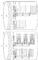
図1は、本実施形態を示す画像形成装置の制御構成を説明するブロック図である。本例は、画像形成装置が画像の入出力と送受信および画像処理を行う複合機として構成した例である。なお、本実施形態に示す画像形成装置は、操作部116からの指示で動作モードを画像形成を実行する通常モードと、画像形成条件を調整するための調整モードとを切り替え可能に構成されている。また、本実施形態では、複合機を例とするが、本発明は、プリンタ機能を実行するプリンタ装置に適用してもよい。
Next, the best mode for carrying out the present invention will be described with reference to the drawings.
<Description of system configuration>
[First Embodiment]
FIG. 1 is a block diagram illustrating a control configuration of the image forming apparatus according to the present exemplary embodiment. In this example, the image forming apparatus is configured as a multi-function machine that performs input / output, transmission / reception of images, and image processing. Note that the image forming apparatus shown in the present embodiment is configured to be able to switch between a normal mode for executing image formation as an operation mode and an adjustment mode for adjusting image forming conditions in response to an instruction from the
図1に示すように、本画像形成装置は、装置全体を制御するコントローラユニット100、画像入力デバイスであるスキャナ114、画像出力デバイスであるプリンタ115、およびユーザからの指示の受付、ユーザへ情報提供を行う操作部116を有する。スキャナ114、プリンタ115、操作部116は、それぞれコントローラユニット100に接続され、コントローラユニット100からの命令によって制御される。
コントローラユニット100は、システムバス108に接続されるデバイスを制御するCPU101を有する。CPU101は、システムバス108を介して、RAM102,ROM103,HDD104,ImagebusI/F105,操作部I/F106、Network I/F 107と接続され、画像形成装置を統括的に制御する。
RAM102は、CPU101の作業領域を提供するためのメモリであり、パラメータ設定値を一時記憶するための設定値記憶メモリであり、また、画像データを一時記憶するための画像メモリとしても使用される。ROM103は、ブートROMであり、ROM103には、システムブートプログラムが格納されている。HDD104には、システムソフトウェア、パラメータ設定値履歴、画像データなどが格納される。ここでHDD104は操作部116を用いてユーザにより設定される通常モードに使用する項目に対するパラメータと、調整モード時に設定される項目に対するパラメータと、設定手段が設定した項目にパラメータを対応づけた履歴情報とを保持可能に構成されている。なお、詳細については図3を用いて詳述する。
As shown in FIG. 1, the image forming apparatus includes a
The
The
操作部I/F106は、操作部116との間で入出力を行うためのインタフェースである。操作部I/F106は、操作部116に表示する画像データを操作部116へ出力し、ユーザが操作部116を介して入力した情報を、CPU101へ伝送する。なお、操作部116は、後述するユーザインタフェース画面(UI画面)を表示する。ユーザは、当該UI画面を用いて、画像形成を行う通常モードと、画像調整を行う調整モードとを切り替えて画像形成に関わる項目に対するパラメータを設定する。ここで設定された項目に対するパラメータは、HDD104に履歴情報として保持管理される。
The operation unit I /
ネットワークI/F107は、LAN117と接続され、LAN117に対して情報の入出力を行う。ImagebusI/F105は、システムバス108と画像バス109とを接続し、データ構造を変換するバスブリッジである。RIP110は、LANから受信されたPDLコードをビットマップイメージに展開する。
デバイスI/F111は、スキャナ114およびプリンタ115とコントローラユニット100を接続し、画像データの同期系/非同期系の変換を行う。またスキャナ114、プリンタ115へ調整値データの伝送を行う。画像バス109には、RIP110と、デバイスI/F111と、スキャナ画像処理部112と、プリンタ画像処理部113とが接続されている。なお、プリンタ115は、CPU101が調整モードで設定した項目に対するパラメータの内容と識別情報とから作成した画像情報を記録用紙に出力する。
The network I /
The device I / F 111 connects the
図2は、図1に示した画像形成装置で調整可能な調整項目の一例を示す図である。本例では、画像形成に関する項目を列挙している。
図2において、画質調整カテゴリ201は、スキャナ画像処理部112とプリンタ画像処理部113とに関する設定群である。画像調整カテゴリ201には、図2に示すように、濃度調整、背景画質調整、カラーバランス調整、読取濃度の調整等がある。また、画像調整カテゴリ201には、像域フラグ処理係数の調整、中間調処理係数の調整、色ずれ補正値の調整等がある。共通設定カテゴリ202は装置全体の共通設定群である。共通設定カテゴリ202には、自動白黒選択時モード優先や、プリント画質を優先するか、画像形成スピードを優先するかを決めるための設定がある。
デバイス設定カテゴリ203は、スキャナ114、プリンタ115の動作に関する設定群である。デバイス設定カテゴリ203に含まれる項目は、調整が必要となる項目であり、各項目に設定されるパラメータによっては形成される画像に大きな影響を与える可能性がある設定を含んでいる。デバイス設定カテゴリ203は、画像書き出し位置の調整や、トナー濃度目標値の調整、印字余白の調整、定着の温度調整、地紋の印字レベルの調整等がある。これら、デバイス設定カテゴリ203の項目については、専門的な知識を持たないユーザが容易に利用してしまうと、画質や印刷物の品質に大きな影響を与えてしまう。例えば、書き出し位置の調整については、値を大きくしすぎると用紙がない箇所にまでトナーを転写しようとしてしまう。また、トナー濃度目標値の調整については、値を上げると濃度が上がるが、値を上げすぎるとトナーの飛散が起こりやすくなる。さらに、定着温度調整については、値を小さくしすぎると、トナーの定着性が低下するし、値を大きくしすぎるとトナーの一部が定着装置の熱ローラによって取りされるために画質が低下する。これらの調整項目は、専門的な知識を持つユーザのみが操作部116で管理者コードを入力し、認証を行ったうえで注意深く設定するのが好ましく、設定履歴によって容易に呼び出されて用いられるのは好ましくない。そのため、本実施形態では、これらの調整項目に関するパラメータが入力されたとしても、それは履歴情報として残さない。
なお、ここで例として示した調整項目以外に、画像形成装置が動作する上で必要な調整項目として、ネットワーク設定、送信受信仕様設定、レポート仕様設定、システム管理者設定などが存在する。これらの調整項目は画像を出力して調整を行うものではないため本実施形態では記載を省略する。
FIG. 2 is a diagram illustrating an example of adjustment items that can be adjusted by the image forming apparatus illustrated in FIG. 1. In this example, items relating to image formation are listed.
In FIG. 2, an image quality adjustment category 201 is a group of settings related to the scanner
The device setting category 203 is a group of settings relating to the operation of the
In addition to the adjustment items shown as examples here, network settings, transmission / reception specification settings, report specification settings, system administrator settings, and the like exist as adjustment items necessary for the operation of the image forming apparatus. Since these adjustment items do not perform adjustment by outputting an image, description thereof is omitted in the present embodiment.
図3は、図1に示したHDD104で保存して管理される情報の保存状態を説明する図である。
本例では、(A)に示す通常モード301、(B)に示す調整モード302の2つのモード別に調整に関する情報が階層的に保存されている状態を示す。
各モードにおいて、調整に関する情報として調整項目とそのパラメータが保存される。これら調整項目とパラメータは、コントローラユニット100内のHDD104内に保存されており、装置動作時など必要に応じて参照、変更される。
モード変更は、ユーザが操作する操作部116からモード変更要求を受け付けることで、通常モード301と調整モード302とを切り替えることができる。
FIG. 3 is a diagram for explaining a storage state of information stored and managed by the
This example shows a state where information regarding adjustment is hierarchically stored for each of two modes, a
In each mode, adjustment items and parameters thereof are stored as information relating to adjustment. These adjustment items and parameters are stored in the
The mode change can be switched between the
図3の(A)は通常モード時のHDD104が保持する情報の保存状態を示し、通常モード301の場合、操作部116からの変更が指示されたパラメータを保存し、画像形成装置が動作する際に参照するパラメータ設定値303がある。そして、画像形成装置の動作時のパラメータ設定値303の内容を履歴情報として保存するパラメータ設定履歴リスト304がある。
FIG. 3A shows a storage state of information held in the
また、パラメータ設定値303には、図2で示した調整項目と各調整項目のパラメータが保存されている。パラメータ設定履歴リスト304の中には、画像形成装置の動作時に保存されたパラメータ設定値が履歴情報として保存されている。ここで保存できる履歴情報の数に制限がある場合には、古い履歴情報から順に削除し、空いた領域に新しい履歴情報を保存する。パラメータ設定履歴リスト304の中の履歴情報から、パラメータ設定値303にパラメータを反映させることが可能である。
The parameter setting value 303 stores the adjustment items shown in FIG. 2 and the parameters of each adjustment item. In the parameter
図3の(B)は調整モード時のHDD104が保持する情報の保存状態を示す。調整モード302の場合では、通常モード301時に使用するパラメータ設定値303、パラメータ設定履歴リスト304に加えて、テンポラリ305、調整値一時保存リスト306が作成され、保存されている。
また、調整モード302では、パラメータ設定値303とパラメータ設定履歴リスト304を参照することはできるが、パラメータ設定値303とパラメータ設定履歴リスト304を変更することはできない。テンポラリ305には調整モード302中に変更された調整項目とそのパラメータが保存される。調整値一時保存リスト306には、一時保存情報リスト307とリストID308とが対応づけて保存される。リストID308は複数保存可能であり、各リストIDにつき、複数の調整項目に対応する複数のパラメータを保存可能である。調整モード302中に画像形成装置が動作する際、テンポラリ305に保存された内容を一時保存情報リスト307へ保存し、リストID308を作成する。このときの詳細な動作は後述する。
次に、本発明の第1の実施形態の動作を、図4のフローチャートを参照して説明する。
FIG. 3B shows a storage state of information held by the
In the
Next, the operation of the first embodiment of the present invention will be described with reference to the flowchart of FIG.
図4は、本実施形態を示す画像形成装置の制御方法を説明するフローチャートである。本例において、ユーザは操作部116を通じて、モード変更指示、調整パラメータ設定指示、画像出力指示、調整パラメータ設定履歴復元指示をCPU101へ指示することができる。操作部116から受け付けた指示は、操作部I/F106を通じてコントローラユニット100のCPU101が受け付ける。また、各ステップは、CPU101がROM103、HDD104等に記憶される制御プログラムをRAM102にロードして実行することで実現される。
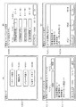
S401では、CPU101は、ユーザが操作する操作部116からモード変更指示を受け付け、画像形成装置の状態を通常モード301から調整モード302へ移行させる。そして、S402に進み、CPU101は、図3の(B)に示したテンポラリ305と、調整値一時保存リスト306をHDD104上に作成する。図5の(A)は、モードが変更され調整モード302に移った際に、CPU101が操作部116に表示するユーザインタフェース(UI)画面の一例である。
FIG. 4 is a flowchart illustrating a method for controlling the image forming apparatus according to the present exemplary embodiment. In this example, the user can instruct the
In step S <b> 401, the
次に、S403では、CPU101はユーザが上記UI画面上で調整パラメータ設定指示ボタン1001を押下することによりパラメータ設定指示を受け付けたか否かを判断する。ここで、ユーザが調整パラメータ設定指示ボタン1001を押下してパラメータ設定指示を受け付けたとCPU101が判断した場合は、S404へ進み、CPU101は、調整パラメータ設定処理を行う。なお、S404の処理の詳細については、図6を参照して詳細に説明する。
In step S <b> 403, the
一方、S403で、ユーザからパラメータ設定指示を受け付けていないとCPU101が判断した場合は、S405へ進む。そして、S405で、CPU101が上記UI画面上で、画像出力指示ボタン1002を押下して画像出力指示を受け付けたか否かを判断する。ここで、ユーザが画像出力指示ボタン1002を押下して画像出力指示を受け付けたとCPU101が判断した場合は、S406へ進む。そして、S406で、CPU101は、後述する図7を参照して詳細に説明する画像出力処理を実行して、S403へ戻る。
一方、S405で、CPU101が上記UI画面上で、画像出力指示を受け付けていないと判断した場合は、S407へ進む。
そして、S407で、CPU101が上記UI画面上で、調整パラメータ復元指示ボタン1003を押下してパラメータ復元指示を受け付けたか否かを判断する。ここで、パラメータ復元指示を受け付けたとCPU101が判断した場合、S408へ進み、後述する図9に示す調整パラメータ復元処理を実行して、S403へ戻る。
On the other hand, if the
On the other hand, if it is determined in S405 that the
In step S407, the
一方、S407で、パラメータ復元指示を受け付けていないとCPU101が判断した場合、S409へ進み、CPU101が上記UI画面上で、調整終了指示ボタン1004が押下して調整終了指示を受け付けたか否かを判断する。ここで、調整終了指示を受け付けたとCPU101が判断した場合は、S410で、CPU101は、後述する図10に示す調整モード終了処理を実行して、本処理を終了する。
一方、S409で、パラメータ復元指示を受け付けていないとCPU101が判断した場合は、S403へ戻る。
次に、図6を参照して、図4に示したS404の調整パラメータ設定処理について説明する。
On the other hand, if the
On the other hand, if the
Next, the adjustment parameter setting process of S404 shown in FIG. 4 will be described with reference to FIG.
図6は、本実施形態を示す画像形成装置における制御を説明するフローチャートである。本例は、図4に示したS404の調整パラメータ設定処理の詳細手順に対応する。なお、各ステップは、CPU101がROM103、HDD104等に記憶される制御プログラムをRAM102にロードして実行することで実現される。なお、図5の(B)は、図1に示した操作部116の表示部に表示されるユーザインタフェース画面であって、調整パラメータ設定時にユーザに示す調整モード/パラメータ調整画面1005の一例である。本例では、ユーザは項目毎に設定された範囲からパラメータを設定することが可能に構成されている。
FIG. 6 is a flowchart illustrating control in the image forming apparatus showing the present embodiment. This example corresponds to the detailed procedure of the adjustment parameter setting process of S404 shown in FIG. Each step is realized by the
まず、S501では、CPU101は、ユーザが特定の調整項目ボタン1006を押下した場合、当該調整項目ボタン1006を選択状態(反転表示状態)に表示態様を切り替え制御する。なお、他のボタンとの表示態様を切り替えて、ユーザが選択状態を識別可能であれば、表示態様に制限されることはない。
次に、S502で、CPU101は、選択した当該調整項目に対して、ユーザがテンキー等を操作して設定するパラメータ1007を受け付ける。なお、受け付けるパラメータの範囲は設定範囲ガイド1008に示される範囲であり、範囲外の値の通知は受け付けないように制御されている。
First, in step S <b> 501, when the user presses a specific
In step S <b> 502, the
図5の(B)に示す画面は、ユーザが定着温調設定を選択し、当該パラメータに「−2」を入力している状態に対応する。
次に、S503で、CPU101は、S502でユーザにより設定されたパラメータを確定する指示ボタンとして機能するOKボタン1010が押下されているかどうかを判断する。ここで、OKボタン1010が押下されていると判断した場合は、S504へ進む。
一方、S503で、設定パラメータのキャンセルを指示するためのキャンセルボタン1009が押下されているとCPU101が判断した場合、調整パラメータ設定処理を終了する。
次に、S504で、CPU101は、S502で設定される当該調整項目が、図2に示したテンポラリ305内の保存情報に存在するかを判断する。ここで、当該調整項目がテンポラリ305内に存在するとCPU101が判断した場合は、S505へ進みテンポラリ305内にある当該調整項目のパラメータ部分をS502で受け付けたパラメータ1007に変更して、本処理を終了する。
一方、S504で、S502で設定された当該調整項目がテンポラリ305内に存在しないとCPU101が判断した場合には、S506へ進む。S506で、CPU101は、当該調整項目ボタン1006とそのパラメータ1007とをテンポラリ305の保存情報へ新たに追加して、本処理を終了する。
The screen shown in FIG. 5B corresponds to a state in which the user selects the fixing temperature adjustment setting and inputs “−2” as the parameter.
In step S503, the
On the other hand, if the
Next, in step S504, the
On the other hand, if the
図7は、本実施形態を示す画像形成装置における制御を説明するフローチャートである。本例は、図4に示したS406の画像出力処理の詳細手順である。なお、各ステップは、CPU101がROM103、HDD104等に記憶される制御プログラムをRAM102にロードして実行することで実現される。また、本画像出力処理は、画像出力指示を受け付けた場合に実行される。画像出力指示は、ユーザが操作部116を操作して指示される場合と、装置がネットワークに接続されている場合にはネットワーク117経由で指示される場合とがある。ここでは一例としてユーザが操作部116を操作した場合の例について説明する。
FIG. 7 is a flowchart for explaining control in the image forming apparatus showing the present embodiment. This example is a detailed procedure of the image output process of S406 shown in FIG. Each step is realized by the
S601で、CPU101は、ユーザが押下する画像出力指示ボタン1002を受け付ける。そして、S602へ進み、CPU101は、図3の(B)に示した調整値一時保存リスト306に新たな一時保存情報リスト307を追加する。そして、S603へ進み、CPU101は、テンポラリ305に保存している内容を読み出し、S602で追加した一時保存情報リスト307へ格納する。そして、S604で、CPU101は、S602で追加した一時保存情報リスト307に対応付いたリストID308を作成する。
S605で、CPU101は、対応したスキャナ画像処理部112、プリンタ画像処理部113、デバイスI/F111を通じてスキャナ114、プリンタ115から画像出力を行うために必要となる調整項目のパラメータ通知要求を受ける。そして、S606で、CPU101は、テンポラリ305内に当該調整項目が存在するか判断する。ここで、テンポラリ305内に当該調整項目が存在するとCPU101が判断した場合は、S607へ進み、CPU101は、テンポラリ305内の調整値のパラメータを読み出し、S609へ進む。
In step S <b> 601, the
In step S <b> 605, the
一方、S606で、当該調整項目がテンポラリ305内に存在しないとCPU101が判断した場合は、S608へ進み、CPU101は、通常モード301で設定されていたパラメータ設定値303から調整項目のパラメータを読み出す。次に、S609で、S607もしくはS608で読み出した値を当該調整項目に対応した要求元へ通知する。
そして、S610で、CPU101は調整項目のパラメータ通知要求が無くなっているかどうかを判断し、調整項目のパラメータ通知要求が無くなっていないと判断した場合は、S606へ戻り、同様の処理を繰り返す。
On the other hand, if the
In step S610, the
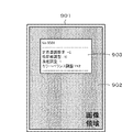
一方、S610で、調整項目のパラメータ通知要求が無くなっていると判断した場合は、S611で、CPU101は、スキャナ114へスキャン動作開始を通知し、デバイスI/F111を経由し画像情報を受け取る。なお、受け取った画像情報はスキャナ画像処理部112で処理されRAM102へ格納する。ここで格納された画像情報の一例を図8に示す画像情報901とする。
次に、S612で、CPU101は、RAM102に格納した画像情報に対して、S604で作成したリストID308とテンポラリ305とから作成した付加情報を合成する。ここで作成する付加情報は、リストID308でもよいし、リストID308に対応した調整値とそのパラメータでもよい。図8に示す付加情報903は、リストID308、テンポラリ305の内容から作成した一例である。本例は、調整モードで設定される項目に対するパラメータの内容を識別情報(No.0001)とから作成される画像情報を記録用紙に画像出力した例である。
On the other hand, if it is determined in S610 that there is no parameter notification request for adjustment items, in S611, the
Next, in S612, the
そして、S613で、CPU101は、RAM102内の画像情報をプリンタ画像処理部113が画像処理を行い、デバイスI/F111経由でプリンタ115へ送信して、本処理を終了する。これにより、プリンタ115ではコントローラユニット100より送信された画像情報の出力を行う。ここで出力される出力物の一例が図8に示す出力物901となる。
ユーザは、出力物901から画像形成装置で設定されたパラメータによる調整結果を判断することができる。ここで調整結果の判断は、出力物901に印字された画像や、出力物901上の画像領域902の位置や、出力物901自体の状態などから行う。
In step S <b> 613, the
The user can determine the adjustment result based on the parameters set by the image forming apparatus from the
図9は、本実施形態を示す画像形成装置における制御を説明するフローチャートである。本例は、図4に示したS408の調整パラメータ復元処理の詳細手順である。なお、各ステップは、CPU101がROM103、HDD104等に記憶される制御プログラムをRAM102にロードして実行することで実現される。なお、調整パラメータ復元処理とは、一時保存情報リスト307から調整パラメータを読み出す読出処理である。
まず、S701で、CPU101は、ユーザが調整パラメータ復元指示ボタン1003を押下したことを受け付ける。図5の(C)は調整パラメータ復元中にユーザに示すユーザインタフェース画面(UI画面)の一例である。なお、図5の(C)は、ユーザが操作部116から入力した識別情報に従い調整モード時にHDD104に保持された項目に対するパラメータを表示した画面に対応する。
FIG. 9 is a flowchart illustrating control in the image forming apparatus showing the present embodiment. This example is a detailed procedure of the adjustment parameter restoration process of S408 shown in FIG. Each step is realized by the
First, in step S <b> 701, the
次に、S702では、CPU101は、ユーザが操作する操作部116から入力されるIDを受け付ける。ここで、IDの入力は、ユーザが操作部116から入力されたIDを受け付けるものとするが、S614で出力された出力物901をスキャナ114に読み込ませ、読み込んだ画像情報の中の付加情報903からID308を抜き出して受け付ける構成としてもよい。ここでは具体的な例として、ユーザが操作部116を操作して直接IDを入力し、操作部I/F106経由でコントローラユニット100においてIDを受け付ける例を示す。このとき操作部116は調整モード/パラメータ復元1011を表示しており、CPU101は、ID1012を入力後に、確認指示ボタン1013の押下を受け付ける。
In step S <b> 702, the
次に、S703では、CPU101は、受け付けたID1012と、一致するIDを調整値一時保存リスト306内のリストID308から検索し、一致するIDが存在するか否かを判断する。ここで、一致するIDが存在するとCPU101が判断した場合には、S704へ進み、一致したIDにCPU101は、対応する一時保存情報リスト307に保存された調整項目とパラメータを読み出す。そして、S705で、CPU101は、その情報を一時情報表示欄1014へ表示する。
次に、S706で、CPU101は、復元指示ボタン1015または、キャンセル指示ボタン1016の押下指示を受け付ける。ここで、復元指示ボタン1015の押下指示を受け付けたとCPU101が判断した場合には、S707へ進む。
In step S <b> 703, the
In step S <b> 706, the
一方、キャンセル指示ボタン1016の押下指示を受け付けたとCPU101が判断した場合には、本調整パラメータ復元処理を終了する。
そして、S707で、CPU101は、図3の(B)に示したHDD104上に作成したテンポラリ305の内容を削除する。
次に、S708で、CPU101は、一致したIDの一時保存情報リスト307から読み出した情報をテンポラリ305へ格納して、本処理を終了する。
一方、S703で、一致するIDが存在しないとCPU101が判断した場合にはS709へ進む。S709で、CPU101は、受け付けたID1012が調整値一時保存リスト306内に存在しないことを操作部I/F106を経由して操作部116へ通知して、本処理を終了する。
On the other hand, if the
In step S707, the
In step S <b> 708, the
On the other hand, if the
以下、具体的な調整パラメータ復元処理の例を説明する。
ここでは、図8に示した出力物901に記載された付加情報903からID「0001」をユーザが操作部116から入力する。すると、CPU101は、ID「0001」を受け付ける。そして、CPU101は、調整値一時保存リスト306の中のリストID308から一致するものを検索し、「0001」に対応する一時保存情報リスト307から一時情報表示欄1014へ表示する。ここでの表示内容は出力物の付加情報903と一致する。復元指示ボタン1015を受け付けるとテンポラリ内に一時情報表示欄1014に示した調整項目とパラメータが保存される。
Hereinafter, a specific example of the adjustment parameter restoration process will be described.
Here, the user inputs the ID “0001” from the
図10は、本実施形態を示す画像形成装置における制御を説明するフローチャートである。本例は、図4に示したS410の調整モード終了処理の詳細手順である。なお、各ステップは、CPU101がROM103、HDD104等に記憶される制御プログラムをRAM102にロードして実行することで実現される。以下、CPU101がパラメータ更新後、前記調整モード時に保持手段に保持されたパラメータの項目に保存禁止項目が含まれているかどうかを判定する処理について説明する。また、CPU101が、判定結果に従って設定された項目とパラメータとを含む履歴情報をHDD104に保存制御する処理について説明する。
まず、S801で、CPU101は、ユーザが調整終了指示ボタン1004の押下指示を受け付ける。図5の(D)はモード終了処理時にユーザに示す操作部116に表示されるUI画面の一例である。
FIG. 10 is a flowchart illustrating control in the image forming apparatus showing the present embodiment. This example is a detailed procedure of the adjustment mode end process of S410 shown in FIG. Each step is realized by the
First, in step S <b> 801, the
次に、S802へ進み、CPU101は、図3の(D)に示したテンポラリ305の内容を通常モード301のパラメータ設定値303として保存するか否かの指示を行うためのボタンを操作部116に表示する。具体的に、CPU101は、Yesボタン1019、Noボタン1020、キャンセルボタン1021を操作部116に表示する。このとき、CPU101は、図3の(D)に示すようにテンポラリ305の内容を現状設定表示欄1018に表示する。ここで、反映しないを指示するNoボタン1020の押下指示をユーザから受け付けたとCPU101が判断した場合には、S804へ進む。
Next, the process advances to step S <b> 802, and the
一方、反映する指示するYesボタン1019の押下指示を受け付けたとCPU101が判断した場合には、S803へ進む。そして、S803で、CPU101は、テンポラリ305に保存してある調整項目のパラメータを、通常モード301のパラメータ設定値303内の対応する調整項目のパラメータに保存する。
On the other hand, if the
次に、S804へ進み、CPU101は、調整値一時保存リスト306を通常モード301のパラメータ設定履歴リスト304として保存するか否かの選択指示をユーザから受け付ける。ここで、ユーザから保存しない選択指示を受け付けたとCPU101が判断した場合には、S807へ進む。
一方、ユーザから保存する選択指示を受け付けたとCPU101が判断した場合には、S805へ進み、調整値一時保存リスト306の一時保存情報リスト307内の調整項目に保存禁止項目を含むか否かを判断する。本実施形態での保存禁止項目は、図2のデバイス設定カテゴリ203に含まれる調整項目が対応する。
In step S804, the
On the other hand, if the
ここで、保存禁止項目を含まないとCPU101が判断した場合には、S806へ進み、CPU101は、当該一時保存情報リスト307を、通常モード301のパラメータ設定履歴リスト304に追加する。これにより、操作部106に表示された項目に対するパラメータで通常モード時のパラメータの内容が更新される。
一方、S805で、一時保存情報リスト307内の調整項目に保存禁止項目を含むとCPU101が判断した場合には、S807へ進む。ここで一例とし、図5の(C)に示された設定がリストID308「0001」を持つとき、通常モード301のパラメータ設定履歴リストに保存する選択指示をユーザから受け付けたとする。すると、S805で、リストID308「0001」に対応する一時保存情報リスト307の中に、デバイス設定カテゴリ203の項目を含むか判断を行う。この一時保存情報リスト307の中に「定着温調設定」を含むため、S807へ進む。
If the
On the other hand, if the
次に、S807で、CPU101は、調整値一時保存リスト306内の全ての一時保存情報リスト307と、全てのリストID308とを削除する。ここで、CPU101は、リストID308に対応する一時保存情報リスト307は保存せずに削除する。
次に、S808で、CPU101は、図3の(B)に示したテンポラリ305をHDD104から削除する。そして、S809へ進み、CPU101は、画像形成装置の状態を調整モード302から通常モード301へ移行させて、本処理を終了する。本実施形態では、一時保存情報リスト307に保持された項目に保存禁止項目が含まれていると判断した場合、調整モード時に設定された項目のパラメータを削除させるので、好ましくない履歴情報がHDD104に保持させてしまうことを防止できる。また、一時保存情報リスト307に保持された項目に保存禁止項目が含まれていないと判断した場合、調整モード時に設定された項目のパラメータを新たな履歴情報としてHDD104に保持させることができる。
In step S <b> 807, the
In step S <b> 808, the
本実施形態では、画像処理に関わる一部の設定だけでなく装置の動作に関わるような設定内容でも一時的に保存し、任意のタイミングで一時設定として復元することができる。そして、調整モードを終了する際に、調整目的以外では変更することを禁じたい調整値、パラメータを含む設定であれば復元できないようにし、含まない設定であれば、復元できるよう履歴に残すことになる。
これにより画像形成装置の多くの設定を効率的に履歴情報として管理し、好ましい設定に従って画像処理条件を調整できるようになる。そして、専門の知識を持った管理者以外のユーザに変更させたくない画像への影響が大きい項目については復元できないようにすることで誤動作による機器への影響も防ぐことができる。
In the present embodiment, not only a part of settings related to image processing but also setting contents related to the operation of the apparatus can be temporarily saved and restored as a temporary setting at an arbitrary timing. When exiting the adjustment mode, settings that include adjustment values and parameters that should not be changed except for the purpose of adjustment should not be restored. Become.
As a result, many settings of the image forming apparatus can be efficiently managed as history information, and image processing conditions can be adjusted in accordance with preferable settings. Further, it is possible to prevent an influence on a device due to a malfunction by making it impossible to restore an item that has a large influence on an image that is not desired to be changed by a user other than an administrator having specialized knowledge.
〔第2実施形態〕
上記実施形態では、調整値一時保存リストに対応づけるIDとリストに保存されたパラメータから作成する付加情報について、文字の印字で上記実施形態を説明したが、付加情報を描画できれば実現方法は問わない。二次元コードや電子透かしを付加情報として画像情報に合成し、パラメータ復元時に、画像を読み込み解析することでIDを特定して復元できてもよい。
なお、各フローチャートに示した手順は、一例であって、いずれかのステップ実行順序を入れ替えたり、他の処理を組み入れて構成してもよい。
また、操作部116に表示されたUI画面を、外部の表示装置、例えば表示装置を備える携帯型のデータ処理装置と有線や無線で通信することで表示するように制御してもよい。
また、UI画面をネットワーク上のサーバ装置から取得して表示する構成としてもよい。さらに、HDD104で保持される履歴情報をクラウドコンピューティング環境で管理して、画像形成装置側のメモリ負担を軽減できるように構成してもよい。
また、画像形成装置で、操作部116を介して、デバイス設定カテゴリ203に含まれる調整項目に係るパラメータを変更するための指示を受け付けた場合、操作部116を介して管理者コード(パスワード)の入力を求める構成にしてもよい。そして、管理者コードに基づく認証に成功した場合に、CPU101は、デバイス設定カテゴリ203に含まれる調整項目に係るパラメータを変更することを許可すればよい。一方、管理者コードに基づく認証に成功しなかった場合に、CPU101は、デバイス設定カテゴリ203に含まれる調整項目に係るパラメータを変更することを禁止し、エラーメッセージを表示すればよい。それによって、デバイス設定カテゴリ203に含まれる調整項目のパラメータは、管理者コードを知っている人のみが変更できるようになる。また、そのような調整項目は履歴情報として残されず、管理者コードを知らないユーザが履歴情報に基づいてデバイス設定カテゴリ203に含まれる調整項目のパラメータを設定してしまうことを防ぐことができる。
[Second Embodiment]
In the above-described embodiment, the above-described embodiment has been described by printing characters on the additional information created from the ID associated with the adjustment value temporary storage list and the parameters stored in the list. However, the implementation method is not limited as long as the additional information can be drawn. . A two-dimensional code or digital watermark may be combined with image information as additional information, and the ID may be identified and restored by reading and analyzing the image when restoring parameters.
Note that the procedure shown in each flowchart is an example, and any step execution order may be changed or another process may be incorporated.
In addition, the UI screen displayed on the
Moreover, it is good also as a structure which acquires and displays UI screen from the server apparatus on a network. Furthermore, the history information held in the
Further, when the image forming apparatus receives an instruction for changing a parameter relating to an adjustment item included in the device setting category 203 via the
本発明は上記実施形態に限定されるものではなく、本発明の趣旨に基づき種々の変形(各実施形態の有機的な組合せを含む)が可能であり、それらを本発明の範囲から除外するものではない。 The present invention is not limited to the above embodiment, and various modifications (including organic combinations of the embodiments) are possible based on the spirit of the present invention, and these are excluded from the scope of the present invention. is not.
本発明の各工程は、ネットワーク又は各種記憶媒体を介して取得したソフトウエア(プログラム)をパソコン(コンピュータ)等の処理装置(CPU、プロセッサ)にて実行することでも実現できる。 Each process of the present invention can also be realized by executing software (program) acquired via a network or various storage media by a processing device (CPU, processor) such as a personal computer (computer).
101 画像形成装置
102 クライアントPC
101
Claims (6)
前記設定手段に設定されたパラメータを変更する変更手段と、
前記変更手段によって変更されたパラメータを履歴として記憶する記憶手段と、
前記記憶手段に記憶された履歴を参照することによって、過去に設定されたパラメータを復元する復元手段と、
前記変更手段によって変更されたパラメータに定着温度が含まれるか否かを判定する判定手段と、
前記判定手段による判定の結果に基づき、定着温度が含まれないと判定した場合は前記記憶手段に履歴として記憶させ、定着温度が含まれると判定した場合は前記記憶手段に履歴として記憶させないように制御する制御手段と、
を備えることを特徴とする画像形成装置。 Setting means for setting parameters relating to image formation;
Changing means for changing the parameter set in the setting means;
Storage means for storing parameters changed by the changing means as a history;
Restoring means for restoring parameters set in the past by referring to the history stored in the storage means;
Determination means for determining whether the parameter changed by the changing means includes a fixing temperature ;
If it is determined that the fixing temperature is not included based on the result of determination by the determining unit, it is stored as a history in the storage unit, and if it is determined that the fixing temperature is included, it is not stored as a history in the storage unit. Control means for controlling;
An image forming apparatus comprising:
前記復元手段は、ユーザによって指定されたIDに対応するパラメータを、前記記憶手段を参照することによって取得することを特徴とする請求項1に記載の画像形成装置。 The storage means stores the parameter changed by the changing means in association with an ID for specifying the parameter,
The image forming apparatus according to claim 1, wherein the restoration unit acquires a parameter corresponding to an ID specified by a user by referring to the storage unit.
前記設定工程で設定されたパラメータを変更する変更工程と、
前記変更工程で変更されたパラメータを履歴として記憶する記憶工程と、
前記記憶工程で記憶された履歴を参照することによって、過去に設定されたパラメータを復元する復元工程と、
前記変更工程で変更されたパラメータに定着温度が含まれるか否かを判定する判定工程と、
前記判定工程における判定の結果に基づき、定着温度が含まれないと判定された場合は前記記憶工程で履歴として記憶させ、定着温度が含まれると判定された場合は前記記憶工程で履歴として記憶させないように制御する制御工程と、
を備えることを特徴とする画像形成装置の制御方法。 A setting step for setting parameters relating to image formation;
A changing step for changing the parameters set in the setting step;
A storage step of storing the parameter changed in the changing step as a history;
A restoring step of restoring parameters set in the past by referring to the history stored in the storing step;
A determination step of determining whether the fixing temperature is included in the parameter changed in the changing step;
Based on the determination of the determination in step result, when it is determined not contain fixing temperature is to be stored as a history in the storing step, when it is determined to contain the fixing temperature is not stored as a history in the storing step A control process to control,
An image forming apparatus control method comprising:
Priority Applications (2)
| Application Number | Priority Date | Filing Date | Title |
|---|---|---|---|
| JP2011095349A JP5814604B2 (en) | 2011-04-21 | 2011-04-21 | Image forming apparatus, image forming apparatus control method and program |
| US13/450,077 US8817313B2 (en) | 2011-04-21 | 2012-04-18 | Image forming apparatus and control method of image forming apparatus |
Applications Claiming Priority (1)
| Application Number | Priority Date | Filing Date | Title |
|---|---|---|---|
| JP2011095349A JP5814604B2 (en) | 2011-04-21 | 2011-04-21 | Image forming apparatus, image forming apparatus control method and program |
Publications (3)
| Publication Number | Publication Date |
|---|---|
| JP2012226219A JP2012226219A (en) | 2012-11-15 |
| JP2012226219A5 JP2012226219A5 (en) | 2014-08-21 |
| JP5814604B2 true JP5814604B2 (en) | 2015-11-17 |
Family
ID=47021143
Family Applications (1)
| Application Number | Title | Priority Date | Filing Date |
|---|---|---|---|
| JP2011095349A Expired - Fee Related JP5814604B2 (en) | 2011-04-21 | 2011-04-21 | Image forming apparatus, image forming apparatus control method and program |
Country Status (2)
| Country | Link |
|---|---|
| US (1) | US8817313B2 (en) |
| JP (1) | JP5814604B2 (en) |
Families Citing this family (10)
| Publication number | Priority date | Publication date | Assignee | Title |
|---|---|---|---|---|
| JP2014021726A (en) * | 2012-07-18 | 2014-02-03 | Canon Inc | Distribution device, image forming device, system, control method, and computer program |
| JP6229325B2 (en) * | 2013-06-14 | 2017-11-15 | 株式会社リコー | Information processing apparatus and print processing program |
| JP6103235B2 (en) * | 2013-10-09 | 2017-03-29 | 富士ゼロックス株式会社 | Setting storage device, image forming apparatus, and setting storage control program |
| JP6217909B2 (en) * | 2013-10-09 | 2017-10-25 | 富士ゼロックス株式会社 | Setting storage device, image forming apparatus, and setting storage control program |
| JP6418754B2 (en) * | 2014-02-25 | 2018-11-07 | キヤノン株式会社 | Image processing apparatus and image processing apparatus control method |
| JP6248903B2 (en) * | 2014-11-14 | 2017-12-20 | 京セラドキュメントソリューションズ株式会社 | Setting value acquisition system for inspection of image forming apparatus |
| JP6451266B2 (en) * | 2014-12-02 | 2019-01-16 | コニカミノルタ株式会社 | Image forming apparatus, image forming system, image forming control method, and image forming control program |
| JP2018156375A (en) * | 2017-03-17 | 2018-10-04 | キヤノン株式会社 | Image forming device and control method therefor, and program |
| JP7124459B2 (en) * | 2018-05-31 | 2022-08-24 | 京セラドキュメントソリューションズ株式会社 | Image forming device maintenance system |
| JP7098475B2 (en) * | 2018-08-07 | 2022-07-11 | キヤノン株式会社 | Image processing equipment, image processing methods, and programs |
Family Cites Families (5)
| Publication number | Priority date | Publication date | Assignee | Title |
|---|---|---|---|---|
| JP3696892B2 (en) | 1993-03-08 | 2005-09-21 | キヤノン株式会社 | Color image output apparatus and color image output method |
| JPH10233920A (en) * | 1997-02-18 | 1998-09-02 | Fuji Xerox Co Ltd | Image processor |
| JP4413631B2 (en) * | 2004-01-27 | 2010-02-10 | 京セラミタ株式会社 | Image forming apparatus and control program therefor |
| JP4254838B2 (en) * | 2006-10-11 | 2009-04-15 | コニカミノルタビジネステクノロジーズ株式会社 | Image processing system, image processing apparatus, and program |
| JP2009111825A (en) * | 2007-10-31 | 2009-05-21 | Kyocera Mita Corp | History information management device of image forming apparatus |
-
2011
- 2011-04-21 JP JP2011095349A patent/JP5814604B2/en not_active Expired - Fee Related
-
2012
- 2012-04-18 US US13/450,077 patent/US8817313B2/en not_active Expired - Fee Related
Also Published As
| Publication number | Publication date |
|---|---|
| JP2012226219A (en) | 2012-11-15 |
| US20120268791A1 (en) | 2012-10-25 |
| US8817313B2 (en) | 2014-08-26 |
Similar Documents
| Publication | Publication Date | Title |
|---|---|---|
| JP5814604B2 (en) | Image forming apparatus, image forming apparatus control method and program | |
| JP6458598B2 (en) | Image processing apparatus and information processing apparatus | |
| US10298790B2 (en) | Image-forming apparatus, system, information processing method and storage medium for causing an operation screen to be displayed based on display language information | |
| US10552093B2 (en) | Electronic device and recording medium | |
| JP2006281593A (en) | Image forming device, its controlling method, and image forming system | |
| JP6319584B2 (en) | Image forming system | |
| JP5720892B2 (en) | Display control device, operation display device, image processing device, display control method, and display control program | |
| US11079992B2 (en) | Information processing apparatus having software key display, control method thereof, and program | |
| JP7434403B2 (en) | Printing device, printing device control method, and program | |
| KR102271119B1 (en) | Image forming apparatus, display method, program, and computer-readable storage medium storing program | |
| US8760682B2 (en) | Job processing apparatus, control method therefor, and computer-readable storage medium | |
| JP2015195006A (en) | Information processing apparatus and information processing system | |
| JP6446965B2 (en) | Image forming apparatus | |
| US9374481B2 (en) | Image processing apparatus | |
| CN109561231B (en) | Image forming apparatus with a toner supply device | |
| US10015351B2 (en) | Instruction apparatus, processing apparatus, and processing system | |
| JP2016093943A (en) | Image forming system, image forming method, and program | |
| JP6611033B2 (en) | Multifunction device, server device, and account deletion method | |
| US9584678B2 (en) | Image data storing device, method of storing image data and non-transitory computer readable medium storing program | |
| JP2012222591A (en) | Image processing apparatus, image processing apparatus control method, and image processing apparatus control program | |
| US11265433B2 (en) | Image forming apparatus and control method of image forming apparatus | |
| US11095792B2 (en) | Information-processing device importing therein setting information stored in removable storage medium in accordance with setting instruction information stored therein together with setting information | |
| JP6415234B2 (en) | Image processing apparatus, portable terminal, information processing apparatus, control method for image processing apparatus, and program | |
| KR101269469B1 (en) | Image forming apparatus and image forming system and method for controlling thereof | |
| JP2006031556A (en) | Printing position adjusting apparatus, image forming apparatus, image formation server, image formation system and printing position adjustment program |
Legal Events
| Date | Code | Title | Description |
|---|---|---|---|
| A621 | Written request for application examination |
Free format text: JAPANESE INTERMEDIATE CODE: A621 Effective date: 20140418 |
|
| A521 | Request for written amendment filed |
Free format text: JAPANESE INTERMEDIATE CODE: A523 Effective date: 20140707 |
|
| A131 | Notification of reasons for refusal |
Free format text: JAPANESE INTERMEDIATE CODE: A131 Effective date: 20150217 |
|
| A977 | Report on retrieval |
Free format text: JAPANESE INTERMEDIATE CODE: A971007 Effective date: 20150218 |
|
| A521 | Request for written amendment filed |
Free format text: JAPANESE INTERMEDIATE CODE: A523 Effective date: 20150327 |
|
| RD03 | Notification of appointment of power of attorney |
Free format text: JAPANESE INTERMEDIATE CODE: A7423 Effective date: 20150610 |
|
| TRDD | Decision of grant or rejection written | ||
| A01 | Written decision to grant a patent or to grant a registration (utility model) |
Free format text: JAPANESE INTERMEDIATE CODE: A01 Effective date: 20150825 |
|
| A61 | First payment of annual fees (during grant procedure) |
Free format text: JAPANESE INTERMEDIATE CODE: A61 Effective date: 20150918 |
|
| R151 | Written notification of patent or utility model registration |
Ref document number: 5814604 Country of ref document: JP Free format text: JAPANESE INTERMEDIATE CODE: R151 |
|
| LAPS | Cancellation because of no payment of annual fees |