JP5811597B2 - Pointing system, pointing device, and pointing control method - Google Patents
Pointing system, pointing device, and pointing control method Download PDFInfo
- Publication number
- JP5811597B2 JP5811597B2 JP2011122494A JP2011122494A JP5811597B2 JP 5811597 B2 JP5811597 B2 JP 5811597B2 JP 2011122494 A JP2011122494 A JP 2011122494A JP 2011122494 A JP2011122494 A JP 2011122494A JP 5811597 B2 JP5811597 B2 JP 5811597B2
- Authority
- JP
- Japan
- Prior art keywords
- pointer
- housing
- unit
- area
- pointing
- Prior art date
- Legal status (The legal status is an assumption and is not a legal conclusion. Google has not performed a legal analysis and makes no representation as to the accuracy of the status listed.)
- Active
Links
Images


Classifications
-
- G—PHYSICS
- G06—COMPUTING; CALCULATING OR COUNTING
- G06F—ELECTRIC DIGITAL DATA PROCESSING
- G06F3/00—Input arrangements for transferring data to be processed into a form capable of being handled by the computer; Output arrangements for transferring data from processing unit to output unit, e.g. interface arrangements
- G06F3/01—Input arrangements or combined input and output arrangements for interaction between user and computer
- G06F3/03—Arrangements for converting the position or the displacement of a member into a coded form
- G06F3/033—Pointing devices displaced or positioned by the user, e.g. mice, trackballs, pens or joysticks; Accessories therefor
-
- G—PHYSICS
- G06—COMPUTING; CALCULATING OR COUNTING
- G06F—ELECTRIC DIGITAL DATA PROCESSING
- G06F3/00—Input arrangements for transferring data to be processed into a form capable of being handled by the computer; Output arrangements for transferring data from processing unit to output unit, e.g. interface arrangements
- G06F3/01—Input arrangements or combined input and output arrangements for interaction between user and computer
- G06F3/016—Input arrangements with force or tactile feedback as computer generated output to the user
-
- G—PHYSICS
- G06—COMPUTING; CALCULATING OR COUNTING
- G06F—ELECTRIC DIGITAL DATA PROCESSING
- G06F3/00—Input arrangements for transferring data to be processed into a form capable of being handled by the computer; Output arrangements for transferring data from processing unit to output unit, e.g. interface arrangements
- G06F3/01—Input arrangements or combined input and output arrangements for interaction between user and computer
- G06F3/048—Interaction techniques based on graphical user interfaces [GUI]
- G06F3/0481—Interaction techniques based on graphical user interfaces [GUI] based on specific properties of the displayed interaction object or a metaphor-based environment, e.g. interaction with desktop elements like windows or icons, or assisted by a cursor's changing behaviour or appearance
- G06F3/04812—Interaction techniques based on cursor appearance or behaviour, e.g. being affected by the presence of displayed objects
-
- G—PHYSICS
- G06—COMPUTING; CALCULATING OR COUNTING
- G06F—ELECTRIC DIGITAL DATA PROCESSING
- G06F2203/00—Indexing scheme relating to G06F3/00 - G06F3/048
- G06F2203/01—Indexing scheme relating to G06F3/01
- G06F2203/014—Force feedback applied to GUI
-
- G—PHYSICS
- G06—COMPUTING; CALCULATING OR COUNTING
- G06F—ELECTRIC DIGITAL DATA PROCESSING
- G06F3/00—Input arrangements for transferring data to be processed into a form capable of being handled by the computer; Output arrangements for transferring data from processing unit to output unit, e.g. interface arrangements
- G06F3/01—Input arrangements or combined input and output arrangements for interaction between user and computer
- G06F3/03—Arrangements for converting the position or the displacement of a member into a coded form
- G06F3/033—Pointing devices displaced or positioned by the user, e.g. mice, trackballs, pens or joysticks; Accessories therefor
- G06F3/0346—Pointing devices displaced or positioned by the user, e.g. mice, trackballs, pens or joysticks; Accessories therefor with detection of the device orientation or free movement in a 3D space, e.g. 3D mice, 6-DOF [six degrees of freedom] pointers using gyroscopes, accelerometers or tilt-sensors
Landscapes
- Engineering & Computer Science (AREA)
- General Engineering & Computer Science (AREA)
- Theoretical Computer Science (AREA)
- Human Computer Interaction (AREA)
- Physics & Mathematics (AREA)
- General Physics & Mathematics (AREA)
- User Interface Of Digital Computer (AREA)
- Position Input By Displaying (AREA)
Description
本技術は、画面上に表示されるポインタを移動させるためのポインティングシステム、ポインティングデバイス及びポインティング制御方法に関する。 The present technology relates to a pointing system, a pointing device, and a pointing control method for moving a pointer displayed on a screen.
ディスプレイ上に二次元的に表示されるGUI(Graphical User Interface)を操作するための入力装置として、マウスが広く用いられている。近年においては、マウスに代表される平面操作型の入力装置に限られず、空間操作型の入力装置が多種提案されている。 A mouse is widely used as an input device for operating a GUI (Graphical User Interface) displayed two-dimensionally on a display. In recent years, various input devices of the space operation type have been proposed without being limited to the planar operation type input device represented by the mouse.
例えば特許文献1には、第1の方向の加速度を検出する加速度検出部と、第1の方向と直交する第2の方向の軸回りの角速度を検出する角速度検出部と、上記加速度と角速度に基づき、筐体の第1の方向の速度値を算出する算出手段とを備えた空間操作型の入力装置が記載されている。これにより入力装置の動きに対して、画面上に表示されるポインタの自然な動きを実現でき、操作性の向上が図れるとしている。
For example,
近年、ポインティングシステムには、操作性の更なる向上が求められている。例えば従来のポインティングシステムにおいては、ポインタの移動操作はユーザの視覚認識に依存するところが大きく、操作環境によってはユーザに過度な負担を強いることになる場合がある。このため、ユーザにとってより直感的な操作感が得られるような操作性の向上が求められている。 In recent years, further improvement in operability is required for pointing systems. For example, in a conventional pointing system, the operation of moving the pointer largely depends on the user's visual recognition, and may impose an excessive burden on the user depending on the operation environment. For this reason, the improvement of operativity which can obtain a more intuitive operation feeling for a user is calculated | required.
以上のような事情に鑑み、本技術の目的は、ユーザに直感的な操作感を提示することができるポインティングシステム、ポインティングデバイス及びポインティング制御方法を提供することにある。 In view of the circumstances as described above, an object of the present technology is to provide a pointing system, a pointing device, and a pointing control method that can present an intuitive operational feeling to a user.
本技術の一形態に係るポインティングシステムは、ポインティングデバイスと、制御装置とを具備する。
上記ポインティングデバイスは、筐体と、触覚提示部と、センサ部とを有する。上記触覚提示部は、上記筐体に触覚を提示することが可能に構成される。上記センサ部は、上記筐体に対する操作を検出し画面上のポインタの移動を制御するための操作信号を出力する。
上記制御装置は、領域設定部と、信号生成部とを有する。
上記領域設定部は、上記画面上のオブジェクトの表示領域内に属する第1の領域と、上記オブジェクトの表示領域外に属する第2の領域と、上記第1の領域と上記第2の領域との境界部に属する第3の領域とをそれぞれ設定する。
上記信号生成部は、上記操作信号に基づいて上記画面上のポインタの位置を算出し、上記ポインタが第1の領域に位置するときは上記触覚提示部を第1の駆動モードで駆動する第1の制御信号を生成する。上記信号生成部は、上記ポインタが上記第3の領域に位置するときは上記触覚提示部を上記第1の駆動モードとは異なる第2の駆動モードで駆動する第2の制御信号を生成する。
A pointing system according to an embodiment of the present technology includes a pointing device and a control device.
The pointing device includes a housing, a tactile sense presentation unit, and a sensor unit. The tactile sense presentation unit is configured to be capable of presenting a tactile sense to the casing. The sensor unit detects an operation on the housing and outputs an operation signal for controlling movement of a pointer on the screen.
The control device includes a region setting unit and a signal generation unit.
The area setting unit includes a first area belonging to the display area of the object on the screen, a second area outside the display area of the object, the first area, and the second area. A third region belonging to the boundary is set.
The signal generation unit calculates a position of the pointer on the screen based on the operation signal, and when the pointer is located in the first area, the first tactile display unit is driven in the first drive mode. Control signal is generated. The signal generation unit generates a second control signal for driving the tactile sense presentation unit in a second drive mode different from the first drive mode when the pointer is positioned in the third region.
上記ポインティングシステムによれば、オブジェクトへのポインティング操作時に筐体を通じてユーザへ触覚フィードバックを提示するようにしているため、ユーザの視覚認識による依存度を低減し、より直感的なポインティング操作感を提供することができる。また、ポインタがオブジェクトの表示領域内と表示領域外との境界部に位置するとき、ポインタが表示領域内に位置するときとは異なる触覚を提示するようにしているため、オブジェクトへの適正なポインティング操作を誘導でき、操作感の向上を図ることができる。 According to the above pointing system, since tactile feedback is presented to the user through the housing during the pointing operation to the object, the dependence by the user's visual recognition is reduced, and a more intuitive pointing operation feeling is provided. be able to. In addition, when the pointer is positioned at the boundary between the display area and the outside of the display area, a tactile sensation different from that when the pointer is positioned within the display area is presented. The operation can be guided and the operational feeling can be improved.
触覚提示部によって提示される触覚は、触圧覚、振動覚、動き覚といった機械的刺激のほか、温熱的刺激、電気的刺激等が含まれる。一実施形態としての触覚提示部は、振動を発生させる単数又は複数の振動体で構成される。振動体としては、一軸方向に振動を発生させるボイスコイルモータ、回転する偏心錘の遠心力を利用して多軸方向に振動を発生させる振動モータ等が挙げられる。 The tactile sensation presented by the tactile sense presenting unit includes thermal stimulation, electrical stimulation, and the like in addition to mechanical stimulation such as tactile pressure, vibration, and motion. The tactile sense presenting unit as one embodiment is composed of one or a plurality of vibrating bodies that generate vibrations. Examples of the vibrating body include a voice coil motor that generates vibration in one axial direction, and a vibration motor that generates vibration in multiple axial directions using the centrifugal force of a rotating eccentric weight.
第1の駆動モード及び第2の駆動モードは、触覚の強さ、周期、リズム、これらの組み合わせ等によって適宜設定される。第1の駆動モードと第2の駆動モードとの違いは、ユーザに触覚の違いを認識させることができる態様であれば特に制限されない。触覚提示部が振動体で構成される場合、振動の強さ(振幅)、振動周期(周波数)、振動方向等、ユーザが区別し得る態様で触覚の変更が可能である。 The first drive mode and the second drive mode are appropriately set according to the strength of touch, the period, the rhythm, a combination thereof, and the like. The difference between the first drive mode and the second drive mode is not particularly limited as long as it allows the user to recognize the difference in tactile sensation. When the tactile sense presenting unit is composed of a vibrating body, the tactile sense can be changed in such a manner that the user can distinguish the vibration intensity (amplitude), vibration period (frequency), vibration direction, and the like.
ポインティングデバイスの種類は特に限定されず、空間操作型の入力装置でもよいし、平面操作型の入力装置でもよい。平面操作型の入力装置には、典型的には、卓上で操作するマウスが挙げられる。また、タッチパネルやタッチパッド等のようなユーザの手指の移動を検出することでポインティング操作を可能とする各種入力装置も適用可能である。 The type of the pointing device is not particularly limited, and may be a space operation type input device or a plane operation type input device. The planar operation type input device typically includes a mouse operated on a desktop. Further, various input devices such as a touch panel and a touch pad that can perform a pointing operation by detecting the movement of the user's fingers are also applicable.
画面上に表示されるオブジェクトとしては、例えばアイコンのような、プログラムや実行命令の内容を象徴的に表した図形、画像等が挙げられる。これ以外にも、オブジェクトには、画面に表示された二次元映像あるいは三次元映像が含まれる。この場合、上記領域設定部は、表示されるオブジェクトに応じて、第1〜第3の領域を二次元座標あるいは三次元座標として設定してもよい。 Examples of objects displayed on the screen include graphics, images, and the like that symbolically represent the contents of programs and execution instructions such as icons. In addition to this, the object includes 2D video or 3D video displayed on the screen. In this case, the area setting unit may set the first to third areas as two-dimensional coordinates or three-dimensional coordinates according to the displayed object.
上記ポインティングデバイスが空間操作型の入力装置である場合、上記触覚提示部は、個別に駆動されることで任意の軸方向に振動を発生させることが可能な複数の振動体を含んでもよい。
これにより、ユーザによる筐体の移動操作に応じた種々の触覚を提示することができるとともに、ユーザのポインティング操作を補助する機能を提供することができる。
When the pointing device is a spatial operation type input device, the tactile sense presentation unit may include a plurality of vibrating bodies that can generate vibrations in arbitrary axial directions by being individually driven.
Accordingly, various tactile sensations according to the movement operation of the housing by the user can be presented, and a function for assisting the user's pointing operation can be provided.
例えば一実施形態として、上記信号生成部は、上記筐体の操作により上記ポインタが上記オブジェクトに近づいていると判定したときは、上記筐体の移動方向に向けて上記触覚提示部を駆動する第3の制御信号を生成する。
一方、上記信号生成部は、上記筐体の操作により上記ポインタが上記オブジェクトから遠ざかっていると判定したときは、上記筐体の移動方向とは反対方向に向けて上記触覚提示部を駆動する第4の制御信号を生成する。
これにより、ポインタをオブジェクトへ導くような触覚提示を実現でき、操作感を向上させることができる。
For example, as one embodiment, when the signal generation unit determines that the pointer is approaching the object by operating the housing, the signal generation unit drives the tactile sense providing unit toward the moving direction of the housing. 3 control signals are generated.
On the other hand, when the signal generation unit determines that the pointer is moving away from the object by operating the housing, the signal generation unit drives the tactile sense presentation unit in a direction opposite to the moving direction of the housing. 4 control signals are generated.
Thereby, tactile sensation presentation in which the pointer is guided to the object can be realized, and the operational feeling can be improved.
本技術の一形態に係るポインティングデバイスは、筐体と、触覚提示部と、センサ部と、信号生成部とを具備する。
上記触覚提示部は、上記筐体に触覚を付与することが可能に構成される。
上記センサ部は、上記筐体の空間内における動きを検出し、画面上のポインタの移動を制御するための操作信号を出力する。
上記信号生成部は、上記ポインタが上記画面上のオブジェクトの表示領域内に位置するときは上記触覚提示部を第1の駆動モードで駆動する第1の制御信号を生成する。上記信号生成部は、上記ポインタが上記オブジェクトの周囲の所定領域に位置するときは上記触覚提示部を上記第1の駆動モードとは異なる第2の駆動モードで駆動する第2の制御信号を生成する。
A pointing device according to an embodiment of the present technology includes a housing, a tactile sense presentation unit, a sensor unit, and a signal generation unit.
The tactile sense presentation unit is configured to be capable of giving a tactile sensation to the casing.
The sensor unit detects a movement of the housing in the space and outputs an operation signal for controlling the movement of the pointer on the screen.
The signal generation unit generates a first control signal for driving the tactile sensation presentation unit in a first drive mode when the pointer is positioned within the display area of the object on the screen. The signal generation unit generates a second control signal for driving the tactile sense presentation unit in a second drive mode different from the first drive mode when the pointer is located in a predetermined region around the object. To do.
本技術の一形態に係るポインティング制御方法は、画面上のオブジェクトの表示領域内に属する第1の領域と、上記オブジェクトの表示領域外に属する第2の領域と、上記第1の領域と上記第2の領域との境界部に属する第3の領域とをそれぞれ設定することを含む。
上記画面上のポインタを移動させるポインティングデバイスから出力される操作信号に基づいて、上記画面上のポインタの位置が算出される。
上記ポインタが第1の領域に位置するときは上記ポインティングデバイスは第1の駆動モードで触覚提示し、上記ポインタが上記第3の領域に位置するときは上記ポインティングデバイスは上記第1の駆動モードとは異なる第2の駆動モードで触覚提示する。
A pointing control method according to an aspect of the present technology includes a first area belonging to an object display area on a screen, a second area outside the object display area, the first area, and the first area. Setting a third region belonging to the boundary with the second region.
The position of the pointer on the screen is calculated based on an operation signal output from a pointing device that moves the pointer on the screen.
When the pointer is located in the first area, the pointing device presents a tactile sensation in the first driving mode, and when the pointer is located in the third area, the pointing device is in the first driving mode. Presents a tactile sensation in a different second drive mode.
以上のように本技術によれば、直感的なポインティング操作感を提供することができる。 As described above, according to the present technology, an intuitive pointing operation feeling can be provided.
以下、本技術に係る実施形態を、図面を参照しながら説明する。 Hereinafter, embodiments according to the present technology will be described with reference to the drawings.
<第1の実施形態>
[ポインティングシステム]
図1は、本技術の一実施形態に係るポインティングシステムを示すブロック図である。本実施形態のポインティングシステム100は、入力装置1(ポインティングデバイス)と、制御装置2と、表示装置3とを有する。
<First Embodiment>
[Pointing system]
FIG. 1 is a block diagram illustrating a pointing system according to an embodiment of the present technology. A
ポインティングシステム100は、入力装置1から送信される操作信号を制御装置2で受信し、受信した操作信号に応じて、表示装置3の画面31に表示される画像を制御するものである。表示装置3の画面31は、図中X軸方向に水平方向、Y軸方向に垂直方向、Z軸方向に奥行き方向をそれぞれ有する。
The
表示装置3は、例えば液晶ディスプレイ、EL(Electro-Luminescence)ディスプレイ等が挙げられるが、これらに限られない。表示装置3は、テレビジョン放送等を受信できるディスプレイと一体となった装置でもよい。表示装置3は、画面31上に3次元映像を表示することが可能な、例えば3Dテレビジョンで構成されてもよい。
Examples of the
以下、入力装置1及び制御装置2について説明する。
Hereinafter, the
[入力装置]
入力装置1は、ユーザUが把持できる大きさの筐体10を有する。筐体10は、例えば、y軸方向に高さ方向、x軸方向及びz軸方向に径方向を有する略円柱体であり、筐体10の一方の表面には幾つかの操作キー等が配置されている。
[Input device]
The
本実施形態において、入力装置1は、主として、画面31に表示されたポインタPを移動させるための空間操作型のポインティングデバイスとして構成されている。入力装置1は、空間内でユーザUが筐体10をx軸方向に動かしたとき、ポインタPをX軸方向に移動させる操作信号を生成し、それを制御装置2へ送信する。同様に、ユーザUが筐体10をy軸方向に動かしたとき、ポインタPをY軸方向に移動させる操作信号を生成し、それを制御装置2へ送信する。さらに、ポインタPが三次元映像上を移動できるように画面31に表示されている場合には、ユーザUが筐体10をz軸方向に動かしたとき、ポインタPをZ軸方向に移動させる操作信号を生成し、それを制御装置2へ送信する。
In the present embodiment, the
図2は、入力装置1の内部構成を示すブロック図である。入力装置1は、筐体10と、触覚提示部11と、移動検出部12(センサ部)と、キー入力部13と、情報表示部14と、制御部15と、通信部16と、電源部17とを有する。
FIG. 2 is a block diagram showing the internal configuration of the
触覚提示部11は、筐体10に触覚を提示するアクチュエータを含む。すなわち触覚提示部11は、当該アクチュエータを駆動することで、筐体10を通じてユーザUに触覚を提示する機能を有する。触覚提示部11は、制御部15から出力される駆動信号によって所定の駆動モードで駆動される。
The tactile
図3及び図4は、触覚提示部11の一構成例を示す概略平面図及び概略側面図である。触覚提示部11は、個別に駆動されることで任意の軸方向に振動を発生させることが可能な複数の振動体を含む。本実施形態では、x軸方向に相互に対向する第1の組の振動体111a,111bと、y軸方向に相互に対向する第2の組の振動体111c,111dと、z軸方向に相互に対向する第3の組の振動体111e,111fとを有する。各振動体は例えばボイスコイルモータで構成される。
3 and 4 are a schematic plan view and a schematic side view showing a configuration example of the tactile
図3及び図4に示される矢印の方向は、各振動体111a〜111fの主とする振動発生方向を表している。また矢印の太さは、振動の強さを相対的に表しており、矢印が太いほど強い振動を発生させる。すなわち本実施形態では、各組の振動体は相互に離間する方向へ強い振動をそれぞれ発生させることが可能なように配置されている。振動振幅等は、駆動電流の大きさ等を調整することによって任意に変化させることができる。
The direction of the arrow shown in FIG.3 and FIG.4 represents the main vibration generation direction of each vibrating
上記構成により、任意の振動体を駆動することで、各種の振動パターンで筐体10を振動させることができる。例えば、任意の1つの振動体を駆動することで、x,y及びzの各軸に沿った6方向へ所定の振動を発生させることができる。また、任意の複数の振動体を駆動し、各振動方向の合成ベクトルを生成することで、各軸と交差する任意の方向へ所定の振動を発生させることができる。さらに、各振動体の駆動力や駆動タイミングを制御することで、任意の軸回りへ所定の振動を発生させることができる。
With the above configuration, the
移動検出部12は、空間内で操作される筐体10の動きを検出する慣性センサを含む。慣性センサとして、典型的には、加速度センサ、角速度センサが挙げられる。移動検出部12は、x、y及びzの各軸方向の筐体10の動きを検出可能に構成されるが、その構成は特に限定されない。例えば、各軸方向に沿って加速度センサが配置されてもよいし、単数又は複数の角速度センサを組み合わせて構成されてもよい。その他、地磁気センサや圧力センサ等が併用されてもよい。
The
キー入力部13は、筐体10の表面の適宜の位置に配置された押圧式、スライド式、ジョイスティック式の各種スイッチを含む。キー入力部13は、機械式のキースイッチに限られず、静電式、光学式のスイッチ又はセンサを含んでもよい。また、所定の場合に制御部15からの信号によって任意のスイッチが点灯可能に構成されてもよい。
The
情報表示部14は、筐体10の表面に適宜の大きさで組み込まれたディスプレイで構成される。情報表示部14は、制御部15の出力に基づいて、ポインティングシステム100あるいは入力装置1の動作状態や電池残量等の各種情報を表示する。
The
制御部15は、ROM、RAM、CPU(MPU)を含むコンピュータで構成され、入力装置1の各部へ電源を供給するとともに入力装置1の動作を制御する。制御部15は、移動検出部12及びキー入力部13の出力に基づいて操作信号S1を生成し、通信部16を介して操作信号S1を制御装置2へ送信する。移動検出部12の出力には、筐体10の移動方向や移動速度等、筐体10の動きに関する情報が含まれる。キー入力部13の出力には、クリック操作、テンキー操作等の各種操作のほか、入力装置1の動作設定や表示装置3の表示設定等の各種設定操作に関する情報が含まれる。
The
制御部15は、触覚提示部11へ所定の駆動信号S2を出力する。本実施形態では、通信部16を介して受信した制御装置2からの制御信号S3に基づいて、駆動信号S2を生成する。駆動信号S2には、振動の発生方向、強さ、振動周期等の情報を含む振動パターンが含まれる。制御部15は、制御信号S3の内容に応じた各種の振動パターンに対応する駆動信号S2を生成する。
The
通信部16は、制御装置2の通信部28との間で双方向の通信を可能とする無線通信モジュールで構成されるが、有線通信でもよい。通信方式は特に制限されず、「ZigBee」(登録商標)、「Bluetooth」(登録商標)などの機器間通信でもよいし、インターネットを経由した通信でもよい。
The
電源部17は、入力装置1の電源を構成し、筐体10内部の各部へ必要な電力を供給する。電源部17は、典型的にはバッテリで構成される。バッテリは一次電池でもよいし、二次電池でもよい。また電源部17は、太陽電池で構成されてもよい。なお、有線やワイヤレス給電の場合、電源部17は不要である。
The
[制御装置]
制御装置2は、図1に示すように、ビデオRAM23と、表示制御部24と、MPU25と、RAM26と、ROM27と、通信部28とを有する。
[Control device]
As illustrated in FIG. 1, the
通信部28は、入力装置1から送信された操作信号S1を受信する。MPU25は、その操作信号を解析し、RAM26、及びROM27に格納された各種設定値及びプログラムを用いて各種の演算処理を行う。演算処理の一例として、MPU25は、入力装置1から送信された操作信号S1に基づいて、画面31に表示されるポインタの位置(座標)を算出する。表示制御部24は、MPU25の制御に応じて、主に、表示装置3の画面31に表示するための画面データを生成する。画面データとしては、ポインタP、アイコン、当該アイコンの実行により表示される映像データ等が含まれる。ビデオRAM23は、表示制御部24の作業領域となり、生成された画面データを一時的に格納する。
The
制御装置2は、入力装置1に専用の機器であってもよいし、PC(パーソナルコンピュータ)等の一般的な情報処理装置であってもよい。また、制御装置2は、表示装置3と一体となったコンピュータであってもよい。制御装置2による制御対象機器は、オーディオ/ビジュアル機器、プロジェクタ、ゲーム機器、カーナビゲーション機器等であってもよい。
The
以下、制御装置2の詳細について説明する。
Details of the
制御装置2は、領域設定部と、信号生成部とを有する。
The
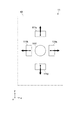
図5は、画面31に表示される画像Vの一例を示す模式図である。領域設定部は、画面31上の画像V(オブジェクト)の表示領域内に属する第1の領域C1と、画像Vの表示領域外に属する第2の領域C2と、第1の領域C1と第2の領域C2との境界部に属する第3の領域C3とをそれぞれ設定する。領域設定部は、MPU25で構成されてもよいし、表示制御部24で構成されてもよいし、これらの両方で構成されてもよい。
FIG. 5 is a schematic diagram illustrating an example of an image V displayed on the
第1の領域C1は画像Vの表示領域内、すなわち画面31の全領域において画像Vが占める表示領域内に設定される。第1の領域C1と画像Vの表示領域とは必ずしも一致していなくてもよく、画像Vの表示領域内に第1の領域C1が設定されていればよい。図5は、実線で示される画像Vの外縁(実線)よりも内方側に第1の領域C1の外縁(破線)が設定された例を示している。
The first area C1 is set in the display area of the image V, that is, in the display area occupied by the image V in the entire area of the
第3の領域C3は、第1の領域C1の外縁に隣接するように設定され、本実施形態では、画像Vの外縁を内包する環状の領域で構成される。この環状の領域における環の幅は適宜設定可能であり、画像Vの形状や大きさや種類、ポインタPの位置の検出感度等に応じて適宜設定可能である。また、ユーザUの操作によって、第3の領域C3の設定幅が変更可能に構成されてもよい。 The third region C3 is set so as to be adjacent to the outer edge of the first region C1, and is configured by an annular region including the outer edge of the image V in this embodiment. The width of the ring in the annular region can be set as appropriate, and can be set as appropriate according to the shape, size, and type of the image V, the detection sensitivity of the position of the pointer P, and the like. Further, the setting width of the third region C3 may be configured to be changeable by the operation of the user U.
画像Vは、典型的にはアイコンであるが、これ以外の二次元映像や三次元映像であってもよい。画像Vが三次元映像の場合、領域C1〜C3のうち少なくとも領域C1は、当該三次元映像に関連付けられた空間領域(空間座標系)で構成される。 The image V is typically an icon, but may be other 2D video or 3D video. When the image V is a 3D image, at least the region C1 of the regions C1 to C3 is configured by a spatial region (spatial coordinate system) associated with the 3D image.
信号生成部は、操作信号S1に基づいて画面31上のポインタPの位置を算出し、ポインタPが第1の領域C1に位置するときは、触覚提示部11を第1の駆動モードで駆動する第1の制御信号(S31)を生成する。また上記信号生成部は、ポインタPが第3の領域C3に位置するときは、触覚提示部11を第1の駆動モードとは異なる第2の駆動モードで駆動する第2の制御信号(S32)を生成する。信号生成部は、例えばMPU25で構成される。MPU25は、生成した制御信号を通信部28へ出力し、通信部28は当該制御信号を入力装置1の通信部16へ送信する。
The signal generation unit calculates the position of the pointer P on the
第1の駆動モード及び第2の駆動モードは、触覚の強さ、周期、リズム、これらの組み合わせ等によって適宜設定される。第1の駆動モードと第2の駆動モードとの違いは、ユーザに触覚の違いを認識させることができる態様であれば特に制限されない。触覚提示部が振動体で構成される本実施形態においては、振動力、振動周期、振動方向等、ユーザが区別し得る態様で触覚の変更が可能である。 The first drive mode and the second drive mode are appropriately set according to the strength of touch, the period, the rhythm, a combination thereof, and the like. The difference between the first drive mode and the second drive mode is not particularly limited as long as it allows the user to recognize the difference in tactile sensation. In the present embodiment in which the tactile sense presenting unit is configured by a vibrating body, the tactile sense can be changed in a manner that the user can distinguish, such as a vibration force, a vibration cycle, and a vibration direction.
信号生成部としてのMPU25は、さらに、ユーザUによる筐体10の操作によりポインタPがアイコン(オブジェクト)に近づいていると判定したとき、筐体10の移動方向に向けて触覚提示部11を駆動する第3の制御信号(S33)を出力するように構成される。一方、信号生成部としてのMPU25は、ユーザUによる筐体10の操作によりポインタPが上記アイコンから遠ざかっていると判定したとき、筐体10の移動方向とは反対方向に向けて触覚提示部11を駆動する第4の制御信号(S34)を出力するように構成される。これにより、ポインタPをアイコンへ導くような触覚提示を実現できるため、ユーザのポインティング操作を補助するような機能が得られ、操作感を向上させることができる。
When the
さらに、信号生成部としてのMPU25は、筐体10の移動速度を算出し、算出されたポインタPの移動速度に応じて触覚提示部11の駆動力を変化させるように構成される。例えば、筐体10の移動速度が大きいほど強い触覚を提示するように、触覚提示部11を駆動してもよい。また、筐体10の移動方向に関連させて触覚提示部11の駆動方向を調整してもよい。このような処理は、MPU25に限られず、入力装置1の制御部15が行ってもよい。
Further, the
[ポインティングシステムの動作例]
次に、ポインティングシステム100の幾つかの動作例を説明する。
[Operation example of pointing system]
Next, several operation examples of the
(動作例1)
図6(A)は、複数のアイコンV1〜V4が間隔をおいて配置された画面31の表示例を示している。図示の例ではアイコンV1〜V4はそれぞれ同一の大きさの矩形状を有し、2行2列のレイアウトで画面31上に表示されている。各アイコンV1〜V4は、ユーザUによるポインタPの移動操作によって選択され、入力装置1の筐体10に配備された操作キーへの入力により実行されるGUIである。
(Operation example 1)
FIG. 6A shows a display example of a
制御装置2は、アイコンV1〜V4の表示領域内、表示領域外、及び、アイコンV1〜V4の境界の所定領域内に、第1の領域C1、第2の領域C2及び第3の領域C3をそれぞれ設定する。これにより、相互に隣接するアイコンV1〜V4の間の領域は、第3の領域C3とされている。
The
画面31上におけるポインタP1の移動は、ユーザUによる入力装置1の空間内での移動操作によって制御される。すなわち、筐体10の動きが入力装置1の移動検出部12によって検出され、入力装置1の制御部15によって筐体10の動きに関する情報を含む操作信号S1が生成される。制御装置2は、入力装置1から送信される操作信号S1を受信し、当該操作信号S1に基づく所定の演算処理によってポインタP1の位置を算出する。そして制御装置2は、筐体10の移動方向及び移動速度に対応する方向及び速度で、画面31上のポインタP1の移動表示を制御する。
The movement of the pointer P1 on the
例えばユーザUがアイコンV3を選択するために、ポインタP1を図6(A)に鎖線で示す位置から実線で示すアイコンV3上の位置に向かって直線的に移動させる場合を考える。アイコンV3の周囲に設定された第3の領域C3にポインタP1が進入すると、制御装置2は第2の駆動モードで触覚提示部11を駆動させるための制御信号S3(S32)を生成し、入力装置1へ送信する。これにより入力装置1は、制御信号S3(S32)に対応する駆動信号S2を生成し、第2の駆動モードによる触覚を触覚提示部11にて発生させる。これによりユーザUは、ポインタP1がアイコンV2に近づいたことを認識することができる。
For example, consider the case where the user U moves the pointer P1 linearly from the position indicated by the chain line in FIG. 6A toward the position on the icon V3 indicated by the solid line in order to select the icon V3. When the pointer P1 enters the third area C3 set around the icon V3, the
次に、アイコンV3の表示領域内に設定された第1の領域C1にポインタP1が進入すると、制御装置2は第1の駆動モードで触覚提示部11を駆動させるための制御信号S3(S31)を生成し、入力装置1へ送信する。これにより入力装置1は、制御信号S3(S31)に対応する駆動信号S2を生成し、第1の駆動モードによる触覚(例えば第2の駆動モードによる触覚よりも強い触覚)を触覚提示部11にて発生させる。第1の駆動モードは第2の駆動モードとは異なる振動パターンで触覚提示部11を駆動するため、ユーザUは、ポインタP1がアイコンV3上に到達したことを確実に認識することができ、アイコンV2の実行操作を適正に行うことが可能となる。
Next, when the pointer P1 enters the first area C1 set in the display area of the icon V3, the
このように本実施形態によれば、アイコンV3へのポインティング操作時に筐体10を通じてユーザUへ触覚フィードバックを提示するようにしているため、ユーザUの視覚認識による依存度を低減し、より直感的なポインティング操作感を提供することができる。また、ポインタP1がアイコンV3の周囲の領域(第3の領域C3)に位置するとき、アイコンV3の表示領域内(第1の領域C1)に位置するときとは異なる触覚を提示するようにしているため、アイコンV3への適正なポインティング操作を誘導でき、操作感の向上を図ることができる。
As described above, according to the present embodiment, since the tactile feedback is presented to the user U through the
一方、図6(B)に示すように、ポインタP1を図中鎖線で示すアイコンV3上の位置から実線で示すアイコンV2上の位置に向かって直線的に移動させる場合を考える。この場合、ポインタP1は第3の領域C3を横切ることになるため、ポインタP1がアイコンV3からアイコンV2へ移動させるときには、第2の駆動モードによる触覚がユーザUへ再度提示された後、アイコンV2に到達したことを示す第1の駆動モードによる触覚がユーザUへ提示される。これによりユーザUは、ポインタP1が当初のアイコンV3から目標とするアイコンV2へ確実に到達したことを認識することができる。 On the other hand, as shown in FIG. 6B, consider a case where the pointer P1 is linearly moved from a position on the icon V3 indicated by a chain line to a position on the icon V2 indicated by a solid line. In this case, the pointer P1 crosses the third area C3. Therefore, when the pointer P1 moves from the icon V3 to the icon V2, the haptic sense in the second driving mode is presented again to the user U, and then the icon V2 is displayed. A tactile sensation in the first drive mode indicating that the position has been reached is presented to the user U. Thereby, the user U can recognize that the pointer P1 has reached the target icon V2 from the original icon V3.
以上のように本実施形態によれば、複数のアイコンが画面上に配列されている場合であっても、各アイコンをポインタが乗り越えるような感覚をユーザへ提示することができるため、ユーザの視覚と触覚とにより所望とするアイコンへポインタを適正に誘導することができる。また、視覚に頼ることなく触覚だけで、アイコン間の行き来を認識することができる。さらに、アイコンごとに第1の駆動モードによる触覚提示パターンを相互に異ならせてもよく、これにより触覚だけで複数のアイコンを個々に区別することが可能となる。 As described above, according to the present embodiment, even when a plurality of icons are arranged on the screen, it is possible to present the user with a sense that the pointer passes over each icon. And the tactile sense can properly guide the pointer to a desired icon. In addition, it is possible to recognize the movement between icons by touch only without relying on vision. Furthermore, the tactile sense presentation pattern in the first drive mode may be different for each icon, and this makes it possible to individually distinguish a plurality of icons only by tactile sense.
(動作例2)
図7及び図8は、ポインタP1でアイコンV5をポインティング操作するときの様子を示す画面の表示例であり、図7はポインタP1が比較的遅い速度で移動する様子を示し、図8はポインタP1が比較的速い速度で移動する様子を示している。また、各図において(A)はポインタP1がアイコンV5に向かって移動する様子を示し、(B)はポインタP1がアイコンV5に到達したときの様子を示している。
(Operation example 2)
7 and 8 are display examples of a screen showing a state when the icon V5 is pointed with the pointer P1, FIG. 7 shows a state in which the pointer P1 moves at a relatively slow speed, and FIG. Shows moving at a relatively fast speed. In each figure, (A) shows how the pointer P1 moves toward the icon V5, and (B) shows how the pointer P1 reaches the icon V5.
ここで、図中の矢印は、ユーザUへ提示される触覚の方向と強さを表し、矢印の軸が太いほど強い触覚を表す。またP0は、ポインタP1の残像群を示しており、移動速度が遅い場合は各像が重なるように表されており(図7)、移動速度が速い場合は各像が離間するように表されている(図8)。また、残像群を構成する各像のうち、淡い色のものほど過去のポインタP1の像を表している。 Here, the arrow in the figure represents the direction and strength of the tactile sensation presented to the user U, and the thicker the axis of the arrow, the stronger the tactile sensation. P0 indicates an afterimage group of the pointer P1, and is represented such that the images overlap when the moving speed is slow (FIG. 7), and the images are separated when the moving speed is fast. (FIG. 8). Of the images constituting the afterimage group, the lighter one represents the past image of the pointer P1.
図7(A)及び図8(A)に示すように、ポインタP1がアイコンV5に向かって移動させる場合において、制御装置2は、筐体10の移動方向に向けて触覚を発生させる制御信号(S33)を生成し、入力装置1へ出力する。入力装置1は、当該制御信号を受信し、制御部15は、筐体10の操作方向に振動を発生させる駆動信号を触覚提示部11へ出力する。図示の例では、触覚提示部11の振動体111b(図3,図4参照)を駆動することで、筐体10の移動方向(−X方向)の触覚を、筐体10を通じてユーザUへ提示する。これにより、ポインタP1をアイコンV5へ導くような触覚提示が実現される。
As shown in FIGS. 7A and 8A, when the pointer P1 is moved toward the icon V5, the
そして図7(B)及び図8(B)に示すように、ポインタP1がアイコンV5に到達したとき、制御装置2は、筐体10の移動方向とは反対方向に触覚を発生させる制御信号を生成し、入力装置1へ出力する。これを受けて、入力装置1の制御部15は、筐体10の操作方向とは反対方向に振動を発生させる駆動信号を触覚提示部11へ出力する。図示の例では、触覚提示部11の振動体111a(図3,図4参照)を駆動することで、筐体10の移動方向とは反対方向(+X方向)の触覚を、筐体10を通じてユーザUへ提示する。これにより、ポインタP1の移動の停止を促す情報をユーザUへ提供することが可能となり、アイコンV5へのポインタP1の誘導効果をさらに一層高めることができる。
Then, as shown in FIGS. 7B and 8B, when the pointer P1 reaches the icon V5, the
また、ポインタP1の移動速度に同期するように触覚の強さを制御することにより、ユーザUに対してポインタP1の移動操作感を高めることができる。図7及び図8の例では、ポインタP1の移動速度が大きいほど弱い触角を提示するとともに、ポインタP1の移動速度が大きいほど、アイコンV5への到達時に提示される移動方向とは反対方向への触覚が大きくなるように設定されるが、勿論これに限られない。 Further, by controlling the strength of the sense of touch so as to synchronize with the moving speed of the pointer P1, it is possible to enhance the feeling of moving operation of the pointer P1 for the user U. In the examples of FIGS. 7 and 8, the greater the moving speed of the pointer P1, the weaker the antenna is presented, and the higher the moving speed of the pointer P1, the more opposite the moving direction presented when the icon V5 is reached. The tactile sensation is set to be large, but of course not limited to this.
さらに、ポインタP1がアイコンV5から離れる方向に移動した場合、筐体10にその移動方向とは反対方向へ触覚を発生させるように制御されてもよい。これにより、ユーザUにポインタP1をアイコンV5の表示位置へ戻すような触覚をユーザUへ提示することができる。
Further, when the pointer P1 moves in a direction away from the icon V5, the
以上のように、ポインタP1の移動速度に同期する触覚をユーザUへ提示することにより、ポインタP1の操作感を高めることができる。また、ポインタP1とアイコンV5との相対位置に関連する触覚をユーザUへ提示することにより、ポインティング操作が容易となり、ユーザUへの負担軽減を図ることが可能となる。 As described above, the sense of operation of the pointer P1 can be enhanced by presenting the user U with a tactile sensation synchronized with the moving speed of the pointer P1. Further, by presenting to the user U a tactile sensation related to the relative position between the pointer P1 and the icon V5, the pointing operation is facilitated, and the burden on the user U can be reduced.
図9は、以上の動作例に基づく制御装置2の処理手順を示す制御フローである。図示するフローは一例であり、仕様や設定に応じて適宜変更可能である。
FIG. 9 is a control flow showing a processing procedure of the
図9において、S10は、入力装置1の移動の有無(仮想オブジェクトとの相対位置の移動の有無)を判定するステップであり、S11は、アイコン(情報)の有無を判定するステップである。S12は、ポインタとアイコンとの位置関係を判定するステップであり、S13及びS14は、アイコンに対するポインタの移動方向を判定するステップである。S15〜S18は、ポインタの移動速度を判定するステップであり、S19〜S26は、提示される触覚の判定結果を実行するステップである。
In FIG. 9, S10 is a step for determining whether or not the
S10において、入力装置1が移動してなければ、入力装置1の移動を検知するまで状態が保持される。入力装置1の移動を検知したとき、S11へ状態が遷移される。S11において、制御装置2は、ポインタP1の近傍に触覚提示を必要とするアイコンV5が存在するか判定し、アイコンV5がなければS10へ遷移し、アイコンV5が存在すればS12へ遷移する。S12において、制御装置2は、ポインタP1とアイコンV5との位置関係を判定する。この判定は、ポインタP1の位置と、アイコンV5の表示領域に対応する第1の領域C1とがそれぞれ参照される。
In S10, if the
ポインタP1がアイコンV5の表示領域内に位置する場合には状態がS13へ遷移し、アイコンV5の表示領域外(例えば近傍)に位置する場合には状態がS14へ遷移する。S13,S14において、制御装置2は、アイコンV5に対するポインタP1の移動方向を判定し、ポインタP1がアイコンV5の内方へ向かっている場合には状態がS15,S17へ遷移し、アイコンV5の外方へ向かっている場合には状態がS16,S18へ遷移する。S15〜S18において、制御装置2は、ポインタP1の移動速度を判定し、所定値よりも遅い場合と速い場合とに分けて、予め設定された触覚の提示内容に対応する制御信号を生成する(S19〜S26)。
When the pointer P1 is located within the display area of the icon V5, the state transitions to S13, and when the pointer P1 is located outside (for example, near) the icon V5, the state transitions to S14. In S13 and S14, the
S19〜S26において、触覚の強度は、相対的な関係を示すものであり絶対的な値を規定するものではない。また本例では、移動速度の判定に「遅い」及び「速い」の2段階の評価を用いたが、これに限定されず、さらに多段階の評価が設定されてもよいし、段階的なものでなく連続的なものであってもよい。またこれらの判定結果はあくまでも一例であり、ユーザにどのような体感を与えるか等、要求される効果によって力の提示方向や強度は適宜変更可能である。 In S19 to S26, the strength of the tactile sensation indicates a relative relationship and does not define an absolute value. In this example, the two-stage evaluation of “slow” and “fast” is used for the determination of the moving speed. However, the evaluation is not limited to this, and a multi-stage evaluation may be set. Instead, it may be continuous. These determination results are merely examples, and the direction and intensity of force can be appropriately changed depending on required effects such as what kind of sensation is given to the user.
(動作例3)
図10は、ポインティングシステム100の他の動作例を説明する画面の表示例を示している。図10において、画像V6は、犬や猫等の小動物を示す。図示せずとも、画像V6の表示領域内には、第1の領域C1が設定され、画像V6の周縁部には第3の領域C3が設定されている。
(Operation example 3)
FIG. 10 shows a display example of a screen for explaining another operation example of the
本例において制御装置2は、第3の領域C3に沿ってポインタP2を移動させたときに、例えば、動物の毛を撫でるような質感を呈する触覚を提示させる駆動モードで触覚提示部11を駆動する制御信号を生成する。一方、ポインタP2を第1の領域C1内で移動させたときは、制御装置2は、例えば、動物とじゃれ合うときの質感を呈する触覚を提示させる駆動モードで触覚提示部11を駆動する制御信号を生成する。これにより、ユーザの視覚や聴覚以外に触覚をも刺激することで、よりリアリティ性のある体感をユーザUへ提供することができる。
In this example, when the
ここで、画像V6は、二次元映像でもよいし三次元映像であってもよい。例えば三次元映像の場合、第1の領域C1を映像に関連した三次元座標に設定することができる。そして、当該領域C1をさらに複数の領域に分割し、これら複数に分割された領域ごとに、異なる触覚を提示できるように触覚提示部11の駆動モード(第1の駆動モード)を変化させてもよい。これにより、画面31の平面方向だけでなく、画面の奥行き方向にも異なる触覚を提示することができる。
Here, the image V6 may be a two-dimensional image or a three-dimensional image. For example, in the case of a 3D image, the first area C1 can be set to 3D coordinates related to the image. Then, even if the region C1 is further divided into a plurality of regions and the drive mode (first drive mode) of the tactile
<第2の実施形態>
図11は、本技術の第2の実施形態に係る入力装置(ポインティングデバイス)の構成を示すブロック図である。以下、第1の実施形態と異なる構成について主に説明し、上述の実施形態と同様の構成については同様の符号を付しその説明を省略または簡略化する。
<Second Embodiment>
FIG. 11 is a block diagram illustrating a configuration of an input device (pointing device) according to the second embodiment of the present technology. Hereinafter, configurations different from those of the first embodiment will be mainly described, and configurations similar to those of the above-described embodiment will be denoted by the same reference numerals, and description thereof will be omitted or simplified.
本実施形態の入力装置101は、筐体10と、触覚提示部11と、移動検出部12(センサ部)と、キー入力部13と、情報表示部14と、制御部15と、通信部16と、電源部17とを有する。制御部15は、信号生成部18を含む。
The
信号生成部18は、ポインタが画面上のアイコン(オブジェクト)の表示領域内(第1の領域C1)に位置するときは触覚提示部11を第1の駆動モードで駆動する第1の制御信号を生成する。一方、信号生成部18は、ポインタが上記アイコンの周囲の所定領域(第3の領域C3)に位置するときは触覚提示部11を第1の駆動モードとは異なる第2の駆動モードで駆動する第2の制御信号を生成する。
When the pointer is positioned within the display area (first area C1) of the icon (object) on the screen, the
すなわち本実施形態では、触覚提示部11の駆動モードに対応する制御信号の生成を、制御装置2ではなく入力装置101で行うように構成されている点で、第1の実施形態と異なる。このような構成によっても第1の実施形態と同様の作用を得ることができる。
That is, this embodiment is different from the first embodiment in that the control signal corresponding to the drive mode of the tactile
本実施形態において、ポインタの位置やアイコンの領域等に関する情報(例えば座標情報)は、制御装置2から送信される制御信号に基づいて判定される。あるいは、入力装置101は、上記座標情報を制御装置2以外の別の機器から取得してもよい。
In the present embodiment, information (for example, coordinate information) regarding the position of the pointer, the icon area, and the like is determined based on a control signal transmitted from the
以上、本技術の実施形態について説明したが、本技術は上述の実施形態にのみ限定されるものではなく、本技術の要旨を逸脱しない範囲内において種々変更を加え得ることは勿論である。 As mentioned above, although embodiment of this technique was described, this technique is not limited only to the above-mentioned embodiment, Of course, in the range which does not deviate from the summary of this technique, various changes can be added.
例えば以上の実施形態では、ポインティングシステム100は、ポインタが第1の領域C1と第3の領域C3とで異なる触覚を提示させる駆動モードで触覚提示部11を駆動するように構成されたが、アイコンの表示領域外に設定された第2の領域C2にポインタが位置するときにも、特有の触覚を提示するような駆動モードが設定されてもよい。
For example, in the above embodiment, the
また、以上の実施形態では、ポインタの移動(方向、速度)に関連した触覚をユーザUに提示する構成を説明したが、これに加えて、ポインタが停止(静止)した状態をユーザUへ認識させる他の触覚提示モードが設定されてもよい。これにより、ポインタの停止、移動を含む操作感をユーザへ提供することができる。 Moreover, although the above embodiment demonstrated the structure which shows the tactile sense relevant to the movement (direction, speed) of a pointer to the user U, in addition to this, the state which the pointer stopped (stationary) is recognized to the user U. Other tactile sense presentation modes may be set. Thereby, it is possible to provide the user with an operational feeling including stopping and moving the pointer.
さらに以上の実施形態では、入力装置1の空間内の動きを慣性センサで検知する例を説明したが、これに代えて又は加えて、イメージセンサにより入力装置1の動きを直接検出してポインタの移動制御を行ってもよい。
Further, in the above embodiment, the example in which the motion in the space of the
さらに、触覚提示部11は振動体による振動作用で筐体10に触覚を付与する構成に限られない。例えば、筐体10の表面を部分的に変形させる、筐体10の内部にモーメントを発生させる、筐体10の表面に電気刺激を付与する電圧を発生させる等の各種機構が採用可能である。
Furthermore, the tactile
なお、本技術は以下のような構成も採ることができる。
(1)筐体と、前記筐体に触覚を提示することが可能な触覚提示部と、前記筐体に対する操作を検出し画面上のポインタの移動を制御するための操作信号を出力するセンサ部とを有するポインティングデバイスと、
前記画面上のオブジェクトの表示領域内に属する第1の領域と、前記オブジェクトの表示領域外に属する第2の領域と、前記第1の領域と前記第2の領域との境界部に属する第3の領域とをそれぞれ設定する領域設定部と、前記操作信号に基づいて前記画面上のポインタの位置を算出し、前記ポインタが第1の領域に位置するときは前記触覚提示部を第1の駆動モードで駆動する第1の制御信号を生成し、前記ポインタが前記第3の領域に位置するときは前記触覚提示部を前記第1の駆動モードとは異なる第2の駆動モードで駆動する第2の制御信号を生成する信号生成部とを有する制御装置と
を具備するポインティングシステム。
(2)上記(1)に記載のポインティングシステムであって、
前記ポインティングデバイスは、空間操作型の入力装置であり、
前記触覚提示部は、個別に駆動されることで任意の軸方向に振動を発生させることが可能な複数の振動体を含む
ポインティングシステム。
(3)上記(1)又は(2)に記載のポインティングシステムであって、
前記信号生成部は、前記筐体の操作により前記ポインタが前記オブジェクトに近づいていると判定したときは、前記筐体の移動方向に向けて前記触覚提示部を駆動する第3の制御信号を生成する
ポインティングシステム。
(4)上記(1)〜(3)の何れか1つに記載のポインティングシステムであって、
前記信号生成部は、前記筐体の操作により前記ポインタが前記オブジェクトから遠ざかっていると判定したときは、前記筐体の移動方向とは反対方向に向けて前記触覚提示部を駆動する第4の制御信号を生成する
ポインティングシステム。
(5)上記(1)〜(4)の何れか1つに記載のポインティングシステムであって、
前記信号生成部は、前記筐体の移動速度を算出し、算出された前記移動速度に応じて前記触角提示部の駆動力を変化させる
ポインティングシステム。
(6)上記(1)〜(5)の何れか1つに記載のポインティングシステムであって、
前記オブジェクトは、アイコンである
ポインティングシステム。
(7)上記(1)〜(6)の何れか1つに記載のポインティングシステムであって、
前記オブジェクトは、三次元映像であり、
前記第1の領域は、前記三次元映像に関連付けられた三次元領域である
ポインティングシステム。
(8)上記(1)〜(7)の何れか1つに記載のポインティングシステムであって、
前記センサ部は、前記筐体の動きを検出し前記動きに関連する信号を生成する慣性センサを含む
ポインティングシステム。
(9)筐体と、
前記筐体に触覚を提示することが可能な触覚提示部と、
前記筐体の空間内における動きを検出し、画面上のポインタの移動を制御するための操作信号を出力するセンサ部と、
前記ポインタが前記画面上のオブジェクトの表示領域内に位置するときは前記触覚提示部を第1の駆動モードで駆動する第1の制御信号を生成し、前記ポインタが前記オブジェクトの周囲の所定領域に位置するときは前記触覚提示部を前記第1の駆動モードとは異なる第2の駆動モードで駆動する第2の制御信号を生成する信号生成部と
を具備するポインティングデバイス。
(10)画面上のオブジェクトの表示領域内に属する第1の領域と、前記オブジェクトの表示領域外に属する第2の領域と、前記第1の領域と前記第2の領域との境界部に属する第3の領域とをそれぞれ設定し、
前記画面上のポインタを移動させるポインティングデバイスから出力される操作信号に基づいて前記画面上のポインタの位置を算出し、
前記ポインタが第1の領域に位置するときは前記ポインティングデバイスを第1の駆動モードで触覚提示させ、前記ポインタが前記第3の領域に位置するときは前記ポインティングデバイスを前記第1の駆動モードとは異なる第2の駆動モードで触覚提示させる
ポインティング制御方法。
In addition, this technique can also take the following structures.
(1) A case, a tactile sense presentation unit capable of presenting a tactile sensation to the case, and a sensor unit that detects an operation on the case and outputs an operation signal for controlling movement of a pointer on the screen A pointing device having:
A first area belonging to the display area of the object on the screen; a second area outside the display area of the object; and a third area belonging to a boundary between the first area and the second area. A region setting unit for setting each of the regions, and a position of the pointer on the screen based on the operation signal. When the pointer is positioned in the first region, the tactile sense providing unit is driven first. Generating a first control signal to be driven in a mode, and driving the tactile sense presentation unit in a second drive mode different from the first drive mode when the pointer is positioned in the third region. And a control device having a signal generation unit that generates the control signal.
(2) The pointing system according to (1) above,
The pointing device is a spatially operated input device,
The tactile sense presentation unit includes a plurality of vibrators that can be driven individually to generate vibrations in an arbitrary axial direction.
(3) The pointing system according to (1) or (2) above,
The signal generation unit generates a third control signal for driving the tactile sense presentation unit in the moving direction of the housing when it is determined that the pointer is approaching the object by the operation of the housing. Pointing system.
(4) The pointing system according to any one of (1) to (3) above,
When the signal generation unit determines that the pointer is moved away from the object by the operation of the housing, the signal generation unit drives the tactile sense presentation unit in a direction opposite to the moving direction of the housing. A pointing system that generates control signals.
(5) The pointing system according to any one of (1) to (4) above,
The signal generation unit calculates a moving speed of the housing, and changes a driving force of the antenna presentation unit according to the calculated moving speed.
(6) The pointing system according to any one of (1) to (5) above,
The object is an icon pointing system.
(7) The pointing system according to any one of (1) to (6) above,
The object is a 3D image,
The pointing system is a three-dimensional region associated with the three-dimensional image.
(8) The pointing system according to any one of (1) to (7) above,
The pointing unit includes an inertial sensor that detects a movement of the housing and generates a signal related to the movement.
(9) a housing;
A tactile sense presentation unit capable of presenting a tactile sense to the housing;
A sensor unit that detects movement in the space of the housing and outputs an operation signal for controlling movement of a pointer on the screen;
When the pointer is positioned within the display area of the object on the screen, a first control signal for driving the tactile sense presentation unit in the first drive mode is generated, and the pointer is moved to a predetermined area around the object. A pointing device comprising: a signal generation unit that generates a second control signal for driving the tactile sense presentation unit in a second drive mode different from the first drive mode when positioned.
(10) The first area belonging to the display area of the object on the screen, the second area outside the display area of the object, and the boundary portion between the first area and the second area Set each of the third areas,
Calculate the position of the pointer on the screen based on an operation signal output from a pointing device that moves the pointer on the screen,
When the pointer is located in the first area, the pointing device is presented in a tactile sense in the first driving mode, and when the pointer is located in the third area, the pointing device is set to the first driving mode. Is a pointing control method in which a tactile sensation is presented in a different second driving mode.
1,101…入力装置
2…制御装置
3…表示装置
10…筐体
11…触覚提示部
12…移動検出部
15…制御部
18…信号生成部
24…表示制御部
25…MPU
31…画面
100…ポインティングシステム
111a〜111f…振動体
C1…第1の領域
C2…第2の領域
C3…第3の領域
P,P1,P2…ポインタ
U…ユーザ
V,V6…画像
V1〜V5…アイコン
DESCRIPTION OF SYMBOLS 1,101 ...
31 ...
Claims (8)
前記画面上のオブジェクトの表示領域内に属する第1の領域と、前記オブジェクトの表示領域外に属する第2の領域と、前記第1の領域と前記第2の領域との境界部に属する第3の領域とをそれぞれ設定する領域設定部と、前記操作信号に基づいて前記画面上のポインタの位置を算出し、前記ポインタが前記第1の領域に位置するときは前記触覚提示部を第1の駆動モードで駆動する第1の制御信号を生成し、前記ポインタが前記第3の領域に位置するときは前記触覚提示部を前記第1の駆動モードとは異なる第2の駆動モードで駆動する第2の制御信号を生成し、前記筐体の移動操作により前記ポインタが前記オブジェクトに近づいていると判定したときは、前記筐体の移動方向へ、当該移動方向とは反対方向よりも強い振動を発生させるように、前記複数の振動体のうち少なくとも1つの振動体を駆動する第3の制御信号を生成する信号生成部とを有する制御装置と
を具備するポインティングシステム。 A housing that is moved and operated in space and a plurality of vibrators that can be individually driven to generate vibrations in an arbitrary axial direction, and can present a tactile sensation to the housing A pointing device having a tactile sense presentation unit and a sensor unit that detects an operation of moving the casing and outputs an operation signal for controlling the movement of the pointer on the screen;
A first area belonging to the display area of the object on the screen; a second area outside the display area of the object; and a third area belonging to a boundary between the first area and the second area. of a region setting unit and a region set respectively, calculates the position of the pointer on the screen based on the operation signal, the pointer is the tactile sense presenting section first when positioned in said first region A first control signal for driving in the driving mode is generated, and when the pointer is located in the third region, the tactile sense providing unit is driven in a second driving mode different from the first driving mode. When the control signal of 2 is generated and it is determined that the pointer is approaching the object by the movement operation of the casing, vibration stronger than the direction opposite to the movement direction is generated in the movement direction of the casing. generate Sea urchin, pointing system comprising a control device and a signal generator for generating a third control signal for driving at least one vibrator of the plurality of vibrators.
前記信号生成部は、前記筐体の移動操作により前記ポインタが前記オブジェクトから遠ざかっていると判定したときは、前記筐体の移動方向とは反対方向へ、当該移動方向よりも強い振動を発生させるように、前記複数の振動体のうち少なくとも1つの振動体を駆動する第4の制御信号を生成する
ポインティングシステム。 The pointing system according to claim 1 ,
When the signal generation unit determines that the pointer is moving away from the object by the movement operation of the housing, the signal generation unit generates a vibration stronger than the movement direction in a direction opposite to the movement direction of the housing . As described above, a pointing system that generates a fourth control signal for driving at least one of the plurality of vibrating bodies .
前記信号生成部は、前記筐体の移動速度を算出し、算出された前記移動速度に応じて前記触覚提示部の駆動力を変化させる
ポインティングシステム。 The pointing system according to claim 1 or 2 ,
The signal generator, the housing pointing system for changing the driving force of the tactile presentation unit according to the moving speed is calculated, and the moving speed calculated in.
前記オブジェクトは、アイコンである
ポインティングシステム。 The pointing system according to any one of claims 1 to 3 ,
The object is an icon pointing system.
前記オブジェクトは、三次元映像であり、
前記第1の領域は、前記三次元映像に関連付けられた三次元領域である
ポインティングシステム。 A pointing system according to any one of claims 1 to 4 ,
The object is a 3D image,
The pointing system is a three-dimensional region associated with the three-dimensional image.
前記センサ部は、前記筐体の動きを検出し前記動きに関連する信号を生成する慣性センサを含む
ポインティングシステム。 A pointing system according to any one of claims 1 to 5 ,
The pointing unit includes an inertial sensor that detects a movement of the housing and generates a signal related to the movement.
個別に駆動されることで任意の軸方向に振動を発生させることが可能な複数の振動体を含み、前記筐体に触覚を提示することが可能な触覚提示部と、
前記筐体の空間内における動きを検出し、画面上のポインタの移動を制御するための操作信号を出力するセンサ部と、
前記ポインタが前記画面上のオブジェクトの表示領域内に位置するときは前記触覚提示部を第1の駆動モードで駆動する第1の制御信号を生成し、前記ポインタが前記オブジェクトの周囲の所定領域に位置するときは前記触覚提示部を前記第1の駆動モードとは異なる第2の駆動モードで駆動する第2の制御信号を生成し、前記筐体の移動操作により前記ポインタが前記オブジェクトに近づいていると判定したときは、前記筐体の移動方向へ、当該移動方向とは反対方向よりも強い振動を発生させるように、前記複数の振動体のうち少なくとも1つの振動体を駆動する第3の制御信号を生成する信号生成部と
を具備するポインティングデバイス。 A casing that is moved and operated in space ;
A tactile sense presentation unit that includes a plurality of vibrators capable of generating vibration in an arbitrary axial direction by being individually driven, and capable of presenting a tactile sense to the housing;
A sensor unit that detects movement in the space of the housing and outputs an operation signal for controlling movement of a pointer on the screen;
When the pointer is positioned within the display area of the object on the screen, a first control signal for driving the tactile sense presentation unit in the first drive mode is generated, and the pointer is moved to a predetermined area around the object. When it is positioned, it generates a second control signal for driving the tactile sense presentation unit in a second drive mode different from the first drive mode, and the pointer moves closer to the object by a movement operation of the housing. A third driving body that drives at least one of the plurality of vibrating bodies so as to generate a stronger vibration in the moving direction of the housing than in a direction opposite to the moving direction. A pointing device comprising: a signal generation unit that generates a control signal .
空間内で移動操作される筐体と、個別に駆動されることで任意の軸方向に振動を発生させることが可能な複数の振動体を含み、前記筐体に触覚を提示することが可能な触覚提示部と、前記筐体の移動操作を検出し前記画面上のポインタの移動を制御するための操作信号を出力するセンサ部とを有するポインティングデバイスの前記センサ部から出力される前記操作信号に基づいて前記画面上のポインタの位置を算出し、
前記ポインタが前記第1の領域に位置するときは前記触覚提示部を第1の駆動モードで駆動し、前記ポインタが前記第3の領域に位置するときは前記触覚提示部を前記第1の駆動モードとは異なる第2の駆動モードで駆動し、前記筐体の移動操作により前記ポインタが前記オブジェクトに近づいていると判定したときは、前記筐体の移動方向へ、当該移動方向とは反対方向よりも強い振動を発生させるように、前記複数の振動体のうち少なくとも1つの振動体を駆動する
ポインティング制御方法。 A first area belonging to an object display area on the screen; a second area outside the object display area; and a third area belonging to a boundary between the first area and the second area. Set each area and
A housing that is moved and operated in space and a plurality of vibrators that can be individually driven to generate vibrations in an arbitrary axial direction, and can present a tactile sensation to the housing a tactile sense presentation unit, the operation signal output from the sensor portion of a pointing device and a sensor section which outputs an operation signal for controlling the movement of detecting a moving operation of the housing pointer on the screen Based on the position of the pointer on the screen,
When the pointer is positioned in the first region drives the tactile sense presentation unit in the first drive mode, the first driving the tactile sense presenting section when the pointer is positioned in the third region When driving in a second drive mode different from the mode and determining that the pointer is approaching the object by a movement operation of the casing, the moving direction of the casing is opposite to the moving direction. A pointing control method for driving at least one of the plurality of vibrating bodies so as to generate a stronger vibration .
Priority Applications (6)
| Application Number | Priority Date | Filing Date | Title |
|---|---|---|---|
| JP2011122494A JP5811597B2 (en) | 2011-05-31 | 2011-05-31 | Pointing system, pointing device, and pointing control method |
| US14/118,590 US9880639B2 (en) | 2011-05-31 | 2012-05-22 | Pointing system, pointing device, and pointing control method |
| EP12793186.3A EP2717117A4 (en) | 2011-05-31 | 2012-05-22 | Pointing system, pointing device, and pointing control method |
| PCT/JP2012/003335 WO2012164871A1 (en) | 2011-05-31 | 2012-05-22 | Pointing system, pointing device, and pointing control method |
| CN201280025026.0A CN103562840A (en) | 2011-05-31 | 2012-05-22 | Pointing system, pointing device, and pointing control method |
| US15/860,013 US10191562B2 (en) | 2011-05-31 | 2018-01-02 | Pointing system, pointing device, and pointing control method |
Applications Claiming Priority (1)
| Application Number | Priority Date | Filing Date | Title |
|---|---|---|---|
| JP2011122494A JP5811597B2 (en) | 2011-05-31 | 2011-05-31 | Pointing system, pointing device, and pointing control method |
Publications (3)
| Publication Number | Publication Date |
|---|---|
| JP2012252398A JP2012252398A (en) | 2012-12-20 |
| JP2012252398A5 JP2012252398A5 (en) | 2014-07-03 |
| JP5811597B2 true JP5811597B2 (en) | 2015-11-11 |
Family
ID=47258748
Family Applications (1)
| Application Number | Title | Priority Date | Filing Date |
|---|---|---|---|
| JP2011122494A Active JP5811597B2 (en) | 2011-05-31 | 2011-05-31 | Pointing system, pointing device, and pointing control method |
Country Status (5)
| Country | Link |
|---|---|
| US (2) | US9880639B2 (en) |
| EP (1) | EP2717117A4 (en) |
| JP (1) | JP5811597B2 (en) |
| CN (1) | CN103562840A (en) |
| WO (1) | WO2012164871A1 (en) |
Cited By (1)
| Publication number | Priority date | Publication date | Assignee | Title |
|---|---|---|---|---|
| JP2019010778A (en) * | 2017-06-29 | 2019-01-24 | 株式会社リコー | Printer and printing method |
Families Citing this family (13)
| Publication number | Priority date | Publication date | Assignee | Title |
|---|---|---|---|---|
| JP5811597B2 (en) | 2011-05-31 | 2015-11-11 | ソニー株式会社 | Pointing system, pointing device, and pointing control method |
| JP6269480B2 (en) * | 2012-04-06 | 2018-01-31 | 株式会社ニコン | Data processing apparatus and data processing program |
| CN103810166A (en) * | 2012-11-06 | 2014-05-21 | 腾讯科技(深圳)有限公司 | Method for looking up contact person in address book and electronic terminal |
| WO2014100554A1 (en) * | 2012-12-20 | 2014-06-26 | Strubwerks Llc | Systems and methods for providing three dimensional enhanced audio |
| WO2014104007A1 (en) * | 2012-12-28 | 2014-07-03 | 株式会社ニコン | Data processing device and data processing program |
| JP6201824B2 (en) * | 2014-03-05 | 2017-09-27 | 株式会社デンソー | Operating device |
| JP6429886B2 (en) * | 2014-09-09 | 2018-11-28 | 三菱電機株式会社 | Touch control system and touch control method |
| USD796534S1 (en) * | 2015-09-30 | 2017-09-05 | Samsung Electronics Co., Ltd. | Display screen or portion thereof with transitional graphical user interface |
| JP6668980B2 (en) * | 2016-07-04 | 2020-03-18 | 富士通株式会社 | Transmission control program, transmission control method, and information processing device |
| WO2018042716A1 (en) * | 2016-08-31 | 2018-03-08 | アルプス電気株式会社 | Operation device |
| JP7043166B2 (en) * | 2016-09-21 | 2022-03-29 | 株式会社デンソーテン | Display control device, display control system and display control method |
| JPWO2021220816A1 (en) * | 2020-04-27 | 2021-11-04 | ||
| US11644907B2 (en) * | 2021-02-26 | 2023-05-09 | Logitech Europe S.A. | Systems, devices, and methods for physical surface tracking with a stylus device in an AR/VR environment |
Family Cites Families (20)
| Publication number | Priority date | Publication date | Assignee | Title |
|---|---|---|---|---|
| US6750877B2 (en) * | 1995-12-13 | 2004-06-15 | Immersion Corporation | Controlling haptic feedback for enhancing navigation in a graphical environment |
| SE519661C2 (en) * | 1996-02-23 | 2003-03-25 | Immersion Corp | Pointing devices and method for marking graphic details on a display with sensory feedback upon finding said detail |
| JPH114966A (en) * | 1996-10-01 | 1999-01-12 | Sony Computer Entateimento:Kk | Operation device for game machine and game device |
| US6252579B1 (en) * | 1997-08-23 | 2001-06-26 | Immersion Corporation | Interface device and method for providing enhanced cursor control with force feedback |
| US6822635B2 (en) * | 2000-01-19 | 2004-11-23 | Immersion Corporation | Haptic interface for laptop computers and other portable devices |
| US6924787B2 (en) * | 2000-04-17 | 2005-08-02 | Immersion Corporation | Interface for controlling a graphical image |
| US7084854B1 (en) * | 2000-09-28 | 2006-08-01 | Immersion Corporation | Actuator for providing tactile sensations and device for directional tactile sensations |
| JP2002236550A (en) * | 2001-02-07 | 2002-08-23 | Fujitsu Ten Ltd | Method and device for screen position input |
| JP2003085590A (en) * | 2001-09-13 | 2003-03-20 | Nippon Telegr & Teleph Corp <Ntt> | Method and device for operating 3d information operating program, and recording medium therefor |
| EP1821180A1 (en) * | 2005-12-31 | 2007-08-22 | Ball-IT Oy | User operable pointing device such as mouse |
| JP2008257295A (en) * | 2007-03-30 | 2008-10-23 | Tokyo Institute Of Technology | Method for presenting tactile stimulus |
| US8941586B2 (en) | 2007-09-12 | 2015-01-27 | Sony Corporation | Input apparatus, control apparatus, control system, and control method |
| US8209628B1 (en) * | 2008-04-11 | 2012-06-26 | Perceptive Pixel, Inc. | Pressure-sensitive manipulation of displayed objects |
| JP4715867B2 (en) | 2008-06-04 | 2011-07-06 | 株式会社デンソー | Operation display control system. |
| US20090303175A1 (en) * | 2008-06-05 | 2009-12-10 | Nokia Corporation | Haptic user interface |
| US20100295667A1 (en) * | 2009-05-22 | 2010-11-25 | Electronics And Telecommunications Research Institute | Motion based pointing apparatus providing haptic feedback and control method thereof |
| US20110012838A1 (en) * | 2009-07-14 | 2011-01-20 | Apple Inc. | Computer input device including a display device |
| US9436280B2 (en) * | 2010-01-07 | 2016-09-06 | Qualcomm Incorporated | Simulation of three-dimensional touch sensation using haptics |
| US8334840B2 (en) * | 2010-01-19 | 2012-12-18 | Visteon Global Technologies, Inc. | System and method of screen manipulation using haptic enable controller |
| JP5811597B2 (en) | 2011-05-31 | 2015-11-11 | ソニー株式会社 | Pointing system, pointing device, and pointing control method |
-
2011
- 2011-05-31 JP JP2011122494A patent/JP5811597B2/en active Active
-
2012
- 2012-05-22 EP EP12793186.3A patent/EP2717117A4/en not_active Withdrawn
- 2012-05-22 CN CN201280025026.0A patent/CN103562840A/en active Pending
- 2012-05-22 US US14/118,590 patent/US9880639B2/en active Active
- 2012-05-22 WO PCT/JP2012/003335 patent/WO2012164871A1/en active Application Filing
-
2018
- 2018-01-02 US US15/860,013 patent/US10191562B2/en active Active
Cited By (1)
| Publication number | Priority date | Publication date | Assignee | Title |
|---|---|---|---|---|
| JP2019010778A (en) * | 2017-06-29 | 2019-01-24 | 株式会社リコー | Printer and printing method |
Also Published As
| Publication number | Publication date |
|---|---|
| US20140085200A1 (en) | 2014-03-27 |
| WO2012164871A1 (en) | 2012-12-06 |
| CN103562840A (en) | 2014-02-05 |
| EP2717117A4 (en) | 2014-12-17 |
| EP2717117A1 (en) | 2014-04-09 |
| US10191562B2 (en) | 2019-01-29 |
| US9880639B2 (en) | 2018-01-30 |
| US20180120955A1 (en) | 2018-05-03 |
| JP2012252398A (en) | 2012-12-20 |
Similar Documents
| Publication | Publication Date | Title |
|---|---|---|
| JP5811597B2 (en) | Pointing system, pointing device, and pointing control method | |
| EP1868063B1 (en) | Tactile - feedback device | |
| EP1927916A1 (en) | Apparatus, method, and medium for outputting tactile feedback on display device | |
| JP2008257295A (en) | Method for presenting tactile stimulus | |
| JP5333397B2 (en) | Information processing terminal and control method thereof | |
| EP2693311A1 (en) | Operation device | |
| JP4445582B2 (en) | Virtual sense presentation device | |
| CN102902373A (en) | Input apparatus, input method, and control system | |
| JP5561092B2 (en) | INPUT DEVICE, INPUT CONTROL SYSTEM, INFORMATION PROCESSING METHOD, AND PROGRAM | |
| KR20160110524A (en) | Game control device, game system, program, and information storage medium | |
| JP2012252398A5 (en) | ||
| RU2636674C2 (en) | Map displaying controller | |
| US20100295667A1 (en) | Motion based pointing apparatus providing haptic feedback and control method thereof | |
| CN103200304A (en) | System and method for controlling mobile terminal intelligent cursor | |
| JP2015147259A (en) | Teaching device for robot | |
| KR101234094B1 (en) | Apparatus for motion based pointing providing haptic feedback and control method thereof | |
| KR101278293B1 (en) | Traveling vibrotactile wave generation method for implementing traveling vibrotactile wave by sequentially driving multiple actuators changing actuators' driving frequency according to the velocity of virtual object and generating continuously varying area of vibrotactile position | |
| JP6376886B2 (en) | Input system and input method | |
| KR101019163B1 (en) | Mouse | |
| JP2005078310A (en) | Tactile presentation device, tactile presentation method and program thereof | |
| JP6809868B2 (en) | Movement guidance device, panel device, control device and movement guidance method | |
| KR20200129454A (en) | A virtual reality or game controller capable of providing travelling vibrotactile wave, a control method, and virtual reality system having the same | |
| KR20100107996A (en) | Pen type tactile representive device having touch face and tactile interface system using thereof | |
| WO2019043787A1 (en) | Vibration control device | |
| KR101156219B1 (en) | A method and a system for producing a partial vibration in a device |
Legal Events
| Date | Code | Title | Description |
|---|---|---|---|
| A521 | Request for written amendment filed |
Free format text: JAPANESE INTERMEDIATE CODE: A523 Effective date: 20140516 |
|
| A621 | Written request for application examination |
Free format text: JAPANESE INTERMEDIATE CODE: A621 Effective date: 20140516 |
|
| A131 | Notification of reasons for refusal |
Free format text: JAPANESE INTERMEDIATE CODE: A131 Effective date: 20150428 |
|
| A521 | Request for written amendment filed |
Free format text: JAPANESE INTERMEDIATE CODE: A523 Effective date: 20150609 |
|
| TRDD | Decision of grant or rejection written | ||
| A01 | Written decision to grant a patent or to grant a registration (utility model) |
Free format text: JAPANESE INTERMEDIATE CODE: A01 Effective date: 20150825 |
|
| A61 | First payment of annual fees (during grant procedure) |
Free format text: JAPANESE INTERMEDIATE CODE: A61 Effective date: 20150907 |
|
| R151 | Written notification of patent or utility model registration |
Ref document number: 5811597 Country of ref document: JP Free format text: JAPANESE INTERMEDIATE CODE: R151 |
|
| R250 | Receipt of annual fees |
Free format text: JAPANESE INTERMEDIATE CODE: R250 |
|
| R250 | Receipt of annual fees |
Free format text: JAPANESE INTERMEDIATE CODE: R250 |
|
| R250 | Receipt of annual fees |
Free format text: JAPANESE INTERMEDIATE CODE: R250 |