JP5802616B2 - Optical information recording / reproducing apparatus and optical information recording / reproducing method - Google Patents
Optical information recording / reproducing apparatus and optical information recording / reproducing method Download PDFInfo
- Publication number
- JP5802616B2 JP5802616B2 JP2012138314A JP2012138314A JP5802616B2 JP 5802616 B2 JP5802616 B2 JP 5802616B2 JP 2012138314 A JP2012138314 A JP 2012138314A JP 2012138314 A JP2012138314 A JP 2012138314A JP 5802616 B2 JP5802616 B2 JP 5802616B2
- Authority
- JP
- Japan
- Prior art keywords
- light
- optical information
- wavefront
- information recording
- reproducing apparatus
- Prior art date
- Legal status (The legal status is an assumption and is not a legal conclusion. Google has not performed a legal analysis and makes no representation as to the accuracy of the status listed.)
- Expired - Fee Related
Links
Images


Classifications
-
- G—PHYSICS
- G11—INFORMATION STORAGE
- G11B—INFORMATION STORAGE BASED ON RELATIVE MOVEMENT BETWEEN RECORD CARRIER AND TRANSDUCER
- G11B7/00—Recording or reproducing by optical means, e.g. recording using a thermal beam of optical radiation by modifying optical properties or the physical structure, reproducing using an optical beam at lower power by sensing optical properties; Record carriers therefor
- G11B7/004—Recording, reproducing or erasing methods; Read, write or erase circuits therefor
- G11B7/0065—Recording, reproducing or erasing by using optical interference patterns, e.g. holograms
-
- G—PHYSICS
- G11—INFORMATION STORAGE
- G11B—INFORMATION STORAGE BASED ON RELATIVE MOVEMENT BETWEEN RECORD CARRIER AND TRANSDUCER
- G11B7/00—Recording or reproducing by optical means, e.g. recording using a thermal beam of optical radiation by modifying optical properties or the physical structure, reproducing using an optical beam at lower power by sensing optical properties; Record carriers therefor
- G11B7/12—Heads, e.g. forming of the optical beam spot or modulation of the optical beam
- G11B7/125—Optical beam sources therefor, e.g. laser control circuitry specially adapted for optical storage devices; Modulators, e.g. means for controlling the size or intensity of optical spots or optical traces
- G11B7/128—Modulators
-
- G—PHYSICS
- G11—INFORMATION STORAGE
- G11B—INFORMATION STORAGE BASED ON RELATIVE MOVEMENT BETWEEN RECORD CARRIER AND TRANSDUCER
- G11B7/00—Recording or reproducing by optical means, e.g. recording using a thermal beam of optical radiation by modifying optical properties or the physical structure, reproducing using an optical beam at lower power by sensing optical properties; Record carriers therefor
- G11B7/12—Heads, e.g. forming of the optical beam spot or modulation of the optical beam
- G11B7/135—Means for guiding the beam from the source to the record carrier or from the record carrier to the detector
- G11B7/1365—Separate or integrated refractive elements, e.g. wave plates
- G11B7/1369—Active plates, e.g. liquid crystal panels or electrostrictive elements
-
- G—PHYSICS
- G11—INFORMATION STORAGE
- G11B—INFORMATION STORAGE BASED ON RELATIVE MOVEMENT BETWEEN RECORD CARRIER AND TRANSDUCER
- G11B7/00—Recording or reproducing by optical means, e.g. recording using a thermal beam of optical radiation by modifying optical properties or the physical structure, reproducing using an optical beam at lower power by sensing optical properties; Record carriers therefor
- G11B7/12—Heads, e.g. forming of the optical beam spot or modulation of the optical beam
- G11B7/135—Means for guiding the beam from the source to the record carrier or from the record carrier to the detector
- G11B7/1392—Means for controlling the beam wavefront, e.g. for correction of aberration
- G11B7/13925—Means for controlling the beam wavefront, e.g. for correction of aberration active, e.g. controlled by electrical or mechanical means
-
- G—PHYSICS
- G11—INFORMATION STORAGE
- G11B—INFORMATION STORAGE BASED ON RELATIVE MOVEMENT BETWEEN RECORD CARRIER AND TRANSDUCER
- G11B7/00—Recording or reproducing by optical means, e.g. recording using a thermal beam of optical radiation by modifying optical properties or the physical structure, reproducing using an optical beam at lower power by sensing optical properties; Record carriers therefor
- G11B7/007—Arrangement of the information on the record carrier, e.g. form of tracks, actual track shape, e.g. wobbled, or cross-section, e.g. v-shaped; Sequential information structures, e.g. sectoring or header formats within a track
- G11B7/00772—Arrangement of the information on the record carrier, e.g. form of tracks, actual track shape, e.g. wobbled, or cross-section, e.g. v-shaped; Sequential information structures, e.g. sectoring or header formats within a track on record carriers storing information in the form of optical interference patterns, e.g. holograms
Landscapes
- Physics & Mathematics (AREA)
- Optics & Photonics (AREA)
- Chemical & Material Sciences (AREA)
- Crystallography & Structural Chemistry (AREA)
- Holo Graphy (AREA)
- Optical Recording Or Reproduction (AREA)
- Optical Head (AREA)
Description
本発明は、ホログラフィを用いて光情報記録媒体に情報を記録、光情報記録媒体から情報を再生する、光情報記録再生装置および光情報記録再生方法に関する。 The present invention relates to an optical information recording / reproducing apparatus and an optical information recording / reproducing method for recording information on an optical information recording medium using holography and reproducing information from the optical information recording medium.
現在、青紫色半導体レーザを用いた、Blu−ray Disc(TM)規格により、民生用においても50GB程度の記録密度を持つ光ディスクの商品化が可能となってきた。今後は、光ディスクでも100GB〜1TBというHDD(Hard Disk Drive)容量と同程度まで大容量化が望まれる。 Currently, the Blu-ray Disc (TM) standard using a blue-violet semiconductor laser has made it possible to commercialize an optical disc having a recording density of about 50 GB even for consumer use. In the future, it is desired to increase the capacity of optical disks to the same level as the HDD (Hard Disk Drive) capacity of 100 GB to 1 TB.
しかしながら、このような超高密度を光ディスクで実現するためには、短波長化と対物レンズ高NA化による高密度化技術とは異なる新しい方式による高密度化技術が必要である。 However, in order to realize such an ultra-high density with an optical disc, a high-density technology by a new method different from the high-density technology by shortening the wavelength and increasing the objective lens NA is necessary.
次世代のストレージ技術に関する研究が行われる中、ホログラフィを利用してデジタル情報を記録するホログラム記録技術が注目を集めている。 While research on next-generation storage technology is underway, hologram recording technology that records digital information using holography is attracting attention.
ホログラム記録技術とは、空間光変調器により2次元的に変調されたページデータの情報を有する信号光を、記録媒体の内部で参照光と重ね合わせ、その時に生じる干渉縞パターンによって記録媒体内に屈折率変調を生じさせることで情報を記録媒体に記録する技術である。 Hologram recording technology is a method in which signal light having page data information two-dimensionally modulated by a spatial light modulator is superimposed on reference light inside the recording medium, and the interference fringe pattern generated at that time is placed in the recording medium. This is a technique for recording information on a recording medium by causing refractive index modulation.
情報の再生時には、記録時に用いた参照光を記録媒体に照射すると、記録媒体中に記録されているホログラムが回折格子のように作用して回折光を生じる。この回折光が記録した信号光と位相情報を含めて同一の光として再生される。 At the time of reproducing information, if the recording medium is irradiated with the reference light used at the time of recording, the hologram recorded in the recording medium acts like a diffraction grating to generate diffracted light. This diffracted light is reproduced as the same light including the recorded signal light and phase information.
再生された信号光は、CMOSやCCDなどの光検出器を用いて2次元的に高速に検出される。このようにホログラム記録技術は、1つのホログラムによって2次元的な情報を一気に光記録媒体に記録し、さらにこの情報を再生することを可能とするものであり、そして、記録媒体のある場所に複数のページデータを重ね書きすることができるため、大容量かつ高速な情報の記録再生を果たすことができる。 The reproduced signal light is detected two-dimensionally at high speed using a photodetector such as a CMOS or CCD. As described above, the hologram recording technique enables two-dimensional information to be recorded on the optical recording medium at once by one hologram and further reproduces this information. Since the page data can be overwritten, large-capacity and high-speed information recording / reproduction can be achieved.
ホログラム記録技術として、例えば特開2004−272268号公報(特許文献1)がある。本公報には、信号光束をレンズで光情報記録媒体に集光すると同時に、平行光束の参照光を照射して干渉させてホログラムの記録を行い、さらに参照光の光記録媒体への入射角度を変えながら異なるページデータを空間光変調器に表示して多重記録を行う、いわゆる角度多重記録方式が記載されている。 As a hologram recording technique, for example, there is JP-A-2004-272268 (Patent Document 1). In this publication, a signal beam is condensed on an optical information recording medium by a lens, and simultaneously, a hologram is recorded by irradiating and collimating a reference beam of a parallel beam, and further determining the incident angle of the reference beam on the optical recording medium. A so-called angle multiplex recording method is described in which multiplex recording is performed by displaying different page data on a spatial light modulator while changing.
またホログラム記録技術の大容量化の手段として、例えば特開2012−27996号公報(特許文献2)がある。本公報には、信号光の各画素に多値の位相情報を付加する方法が記載されている。 As a means for increasing the capacity of the hologram recording technique, for example, there is JP 2012-27996 A (Patent Document 2). This publication describes a method of adding multilevel phase information to each pixel of signal light.
ところで特許文献2において、ホログラム記録媒体からの回折光と、位相情報を付加したオシレーター光とを重ね合わせて干渉させる際に、回折光とオシレーター光との波面がずれることにより正確に位相検出が出来ないという問題があった。 By the way, in Patent Document 2, when the diffracted light from the hologram recording medium and the oscillator light to which the phase information is added are overlapped and interfered with each other, the phase detection can be accurately performed because the wave fronts of the diffracted light and the oscillator light are shifted. There was no problem.
そこで本発明の目的は、回折光とオシレーター光の波面ずれを低減することで再生品質を向上可能な波面補償方法を提供することにある。 Accordingly, an object of the present invention is to provide a wavefront compensation method capable of improving the reproduction quality by reducing the wavefront shift between diffracted light and oscillator light.
上記課題は、特許請求の範囲に記載の発明により解決される。 The above problems are solved by the invention described in the claims.
本発明によれば、ホログラムにおける記録再生処理において回折光とオシレーター光の波面ずれを低減させることができ、再生性能を向上することが可能となる。 According to the present invention, it is possible to reduce the wavefront deviation between the diffracted light and the oscillator light in the recording / reproducing process in the hologram, and it is possible to improve the reproducing performance.
以下、本発明の実施例について図面を用いて説明する。 Embodiments of the present invention will be described below with reference to the drawings.
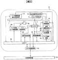
本発明の実施形態を添付図面にしたがって説明する。図2はホログラフィを利用してデジタル情報を記録および/または再生する光情報記録媒体の記録再生装置を示すブロック図である。 Embodiments of the present invention will be described with reference to the accompanying drawings. FIG. 2 is a block diagram showing a recording / reproducing apparatus of an optical information recording medium for recording and / or reproducing digital information using holography.
光情報記録再生装置10は、入出力制御回路90を介して外部制御装置91と接続されている。記録する場合には、光情報記録再生装置10は外部制御装置91から記録する情報信号を入出力制御回路90により受信する。再生する場合には、光情報記録再生装置10は再生した情報信号を入出力制御回路90により外部制御装置91に送信する。
The optical information recording / reproducing
光情報記録再生装置10は、ピックアップ11、再生用参照光光学系12、キュア光学系13、ディスク回転角度検出用光学系14、及び回転モータ50を備えており、光情報記録媒体1は回転モータ50によって回転可能な構成となっている。
The optical information recording / reproducing
ピックアップ11は、参照光と信号光を光情報記録媒体1に出射してホログラフィを利用してデジタル情報を記録媒体に記録する役割を果たす。この際、記録する情報信号はコントローラ89によって信号生成回路86を介してピックアップ11内の空間光変調器に送り込まれ、信号光は空間光変調器によって変調される。
The
光情報記録媒体1に記録した情報を再生する場合は、ピックアップ11から出射された参照光を記録時とは逆の向きに光情報記録媒体に入射させる光波を再生用参照光光学系12にて生成する。再生用参照光によって再生される再生光をピックアップ11内の後述する光検出器によって検出し、信号処理回路85によって信号を再生する。
When reproducing the information recorded on the optical information recording medium 1, the reproduction reference light
光情報記録媒体1に照射する参照光と信号光の照射時間は、ピックアップ11内のシャッタの開閉時間をコントローラ89によってシャッタ制御回路87を介して制御することで調整できる。
The irradiation time of the reference light and the signal light applied to the optical information recording medium 1 can be adjusted by controlling the opening / closing time of the shutter in the
キュア光学系13は、光情報記録媒体1のプリキュアおよびポストキュアに用いる光ビームを生成する役割を果たす。プリキュアとは、光情報記録媒体1内の所望の位置に情報を記録する際、所望位置に参照光と信号光を照射する前に予め所定の光ビームを照射する前工程である。ポストキュアとは、光情報記録媒体1内の所望の位置に情報を記録した後、該所望の位置に追記不可能とするために所定の光ビームを照射する後工程である。 The cure optical system 13 plays a role of generating a light beam used for pre-cure and post-cure of the optical information recording medium 1. Precure is a pre-process for irradiating a predetermined light beam in advance before irradiating the desired position with reference light and signal light when recording information at a desired position in the optical information recording medium 1. Post-cure is a post-process for irradiating a predetermined light beam after recording information at a desired position in the optical information recording medium 1 so that additional recording cannot be performed at the desired position.
ディスク回転角度検出用光学系14は、光情報記録媒体1の回転角度を検出するために用いられる。光情報記録媒体1を所定の回転角度に調整する場合は、ディスク回転角度検出用光学系14によって回転角度に応じた信号を検出し、検出された信号を用いてコントローラ89によってディスク回転モータ制御回路88を介して光情報記録媒体1の回転角度を制御する事が出来る。
The disk rotation angle detection
光源駆動回路82からは所定の光源駆動電流がピックアップ11、キュア光学系13、ディスク回転角度検出用光学系14内の光源に供給され、各々の光源からは所定の光量で光ビームを発光することができる。
A predetermined light source driving current is supplied from the light
また、ピックアップ11、そして、ディスクキュア光学系13は、光情報記録媒体1の半径方向に位置をスライドできる機構が設けられており、アクセス制御回路81を介して位置制御がおこなわれる。
Further, the
ところで、ホログラフィの角度多重の原理を利用した記録技術は、参照光角度のずれに対する許容誤差が極めて小さくなる傾向がある。 By the way, the recording technique using the principle of angle multiplexing of holography tends to have a very small tolerance for the deviation of the reference beam angle.
従って、ピックアップ11内に、参照光角度のずれ量を検出する機構を設けて、サーボ信号生成回路83にてサーボ制御用の信号を生成し、サーボ制御回路84を介して該ずれ量を補正するためのサーボ機構を光情報記録再生装置10内に備えることが必要となる。
Therefore, a mechanism for detecting the deviation amount of the reference beam angle is provided in the
また、ピックアップ11、キュア光学系13、ディスク回転角度検出用光学系14は、いくつかの光学系構成または全ての光学系構成をひとつに纏めて簡素化しても構わない。
Further, the
図3は、光情報記録再生装置10におけるピックアップ11の基本的な光学系構成の一例における記録原理を示したものである。光源201を出射した光ビームはコリメートレンズ202を透過し、シャッタ203に入射する。シャッタ203が開いている時は、光ビームはシャッタ203を通過した後、例えば1/2波長板などで構成される偏光方向変換素子204によってP偏光とS偏光の光量比が所望の比になるように偏光方向を制御された後、偏光ビームスプリッタ205に入射する。
FIG. 3 shows a recording principle in an example of a basic optical system configuration of the
偏光ビームスプリッタ205を透過した光ビームは、ビームエキスパンダ208によって光ビーム径を拡大された後、偏光方向変換素子209、偏光ビームスプリッタ210、および偏光ビームスプリッタ211を経由して空間光変調器212に入射し、空間光変調器212によって例えば図18に示すように画素毎に位相情報が付加されたページデータとなる。ここでページデータ内の位相分布は、例えば光情報記録媒体1のフーリエ面上の光強度分布においてDC強度(いわゆるホットスポット)を除去するような位相分布にする。この様にすることで、従来、DC強度を低減するために用いられていた位相マスクを削除する事ができる。一例としては、各画素に付加した位相の平均値がπとなるような位相分布とする。別の例としては、各画素に付加した位相の平均値が0.5πまたは1.5πとなるような位相分布とする。また別の例としては、1つのページ内において位相=0を基準に位相をランダマイズした画素数と位相πを基準に位相をランダマイズした画素数が等しくなるようにする。
The light beam transmitted through the
なお空間光変調器212は位相変調の機能のみを有する空間光変調器に限定されるものではない。空間光変調器212に振幅変調の機能を持たせることで、空間的に振幅の変調も可能となる。
The
空間光変調器212によってページデータとなった信号光206は偏光ビームスプリッタ211を反射し、リレーレンズ213ならびに空間フィルタ214を伝播する。その後、信号光206は無偏光ビームスプリッタ229を透過後、対物レンズ215によって光情報記録媒体1に集光する。
The
一方、偏光ビームスプリッタ205を反射した光ビームは参照光207として働き、偏光方向変換素子216によって記録時または再生時に応じて所定の偏光方向に設定された後、ミラー217ならびにミラー218を経由して、ミラー219に入射する。なおミラー219はアクチュエータ220によって角度を調整可能であり、レンズ221とレンズ222を通過した後に光情報記録媒体1に入射する。
On the other hand, the light beam reflected from the
このように信号光206と参照光207を光情報記録媒体1において、互いに重ね合うように入射させることで、記録媒体内には干渉縞パターンが形成され、このパターンを記録媒体に書き込むことで情報を記録する。またミラー219によって光情報記録媒体1に入射する参照光207の入射角度を変化させることができるため、角度多重による記録が可能である。
In this way, the
以降、同じ領域に参照光角度を変えて記録されたホログラムにおいて、1つ1つの参照光角度に対応したホログラムをページと呼び、同領域に角度多重されたページの集合をブックと呼ぶことにする。 Hereinafter, in holograms recorded in the same area with different reference beam angles, holograms corresponding to each reference beam angle are called pages, and a set of pages angle-multiplexed in the same area is called a book. .
図4は、光情報記録再生装置10におけるピックアップ11の基本的な光学系構成の一例における再生原理を示したものである。記録時と同様の光路をたどって、参照光207が光情報記録媒体1に入射する。本実施例では位相共役光による再生の方法をとっており、アクチュエータ223によって駆動されるミラー224を反射して再度、光情報記録媒体1に入射する参照光207を用いて情報を再生する。光情報記録媒体1から回折された回折光231は対物レンズ215、無偏光ビームスプリッタ229、リレーレンズ213、空間フィルタ214、偏光ビームスプリッタ211を介して、光検出器225に入射する。
FIG. 4 shows the principle of reproduction in an example of the basic optical system configuration of the
また、光検出器225において回折光231と干渉させるオシレーター光230を生成するため、偏光方向変換素子204によって偏光方向が制御され、所望の光量が偏光ビームスプリッタ205を透過する。偏光ビームスプリッタ205を透過したオシレーター光230は、ビームエキスパンダ208を透過した後、偏光方向変換素子209によって偏光方向が制御され、偏光ビームスプリッタ210を反射する。その後、オシレーター光230は、1/2波長板226によって偏光方向が90度回転し、ミラー227を反射した後、空間光変調器228に入射する。空間光変調器228では、所定の基準位相に加えて、該基準位相に対して90度、180度、270度異なる少なくとも4つの位相をオシレーター光230に付加する。無偏光ビームスプリッタ229を反射したオシレーター光230は、リレーレンズ213、空間フィルタ214、偏光ビームスプリッタ211を介して光検出器225に入射し、前述した回折光231と重ね合わさって干渉する。
Further, in order to generate the
図5は、光検出器225における画素の配置、回折光231およびオシレーター光230の位置関係を示した概略図である。なお図5は、位相変調に加えて振幅変調を行ったページデータを示しているが、振幅変調を行わないホワイトページデータであっても構わない。光検出器上の画素は、ページデータの各画素に対して少なくとも4つの画素でオーバーサンプリングする様に画素が配置されており、前述した4つの位相(基準位相(本実施例では便宜上、0°とする)、基準位相+90°、基準位相+180°、基準位相+270°)を付加された前記オシレーター光230が、オーバーサンプリングを行う前記4つの画素の各々の画素に入射する構成となっている。ここで図中において用いたI1とI2は、基準位相を付加したオシレーター光230が入射する画素からの出力値から基準位相+180°を付加したオシレーター光230が入射する画素からの出力値を引いた値をI1、基準位相+270°を付加したオシレーター光230が入射する画素からの出力値から基準位相+90°を付加したオシレーター光230が入射する画素からの出力値を引いた値をI2としている。
なお便宜上、図5は光検出器225の一部の画素に対する回折光231およびオシレーター光230の位置関係を描写しているが、基本的に本発明ではオーバーサンプリングに用いる4つの画素の全ての組み合わせに対して、同様の位置関係が成り立つものとする。
FIG. 5 is a schematic diagram showing the arrangement of pixels in the
For convenience, FIG. 5 depicts the positional relationship of the diffracted
この様な構成とすることで、干渉計などで一般的に用いられているフリンジスキャン法の原理を用いて、各画素に入射する回折光231とオシレーター光230に付加した基準位相との位相差Δφを図5で定義したI1とI2を用いて(数1)によって算出することが出来るので、ページデータの各画素に付加された位相情報を検出する事ができる。
With such a configuration, the phase difference between the diffracted light 231 incident on each pixel and the reference phase added to the

なお、位相多値記録を行わずに振幅変調を行ったページデータを再生互換する場合は、例えばオシレーター光230の生成手段の動作を停止して、オシレーター光の生成を止めて再生を行うことで、装置の再生互換を実現できる。また、光検出器225としては例えばCMOSイメージセンサーやCCDイメージセンサーなどの撮像素子を用いることができるが、ページデータを再生可能であれば、どのような素子であっても構わない。
In addition, when reproducing and compatibilizing page data that has been subjected to amplitude modulation without performing phase multilevel recording, for example, the operation of the generation unit of the
図6は、光情報記録再生装置10における記録、再生の動作フローを示したものである。ここでは、特にホログラフィを利用した記録再生に関するフローを説明する。
FIG. 6 shows an operation flow of recording and reproduction in the optical information recording / reproducing
図6(a)は、光情報記録再生装置10に光情報記録媒体1を挿入した後、記録または再生の準備が完了するまでの動作フローを示し、図6(b)は準備完了状態から光情報記録媒体1に情報を記録するまでの動作フロー、図6(c)は準備完了状態から光情報記録媒体1に記録した情報を再生するまでの動作フローを示したものである。
FIG. 6A shows an operation flow from when the optical information recording medium 1 is inserted into the optical information recording / reproducing
図6(a)に示すように媒体を挿入すると(601)、光情報記録再生装置10は、例えば挿入された媒体がホログラフィを利用してデジタル情報を記録または再生する媒体であるかどうかディスク判別を行う(602)。
When a medium is inserted as shown in FIG. 6A (601), the optical information recording / reproducing
ディスク判別の結果、ホログラフィを利用してデジタル情報を記録または再生する光情報記録媒体であると判断されると、光情報記録再生装置10は光情報記録媒体に設けられたコントロールデータを読み出し(603)、例えば光情報記録媒体に関する情報や、例えば記録や再生時における各種設定条件に関する情報を取得する。
As a result of disc discrimination, when it is determined that the optical information recording medium records or reproduces digital information using holography, the optical information recording / reproducing
コントロールデータの読み出し後は、コントロールデータに応じた各種調整やピックアップ11に関わる学習処理(604)を行い、光情報記録再生装置10は、記録または再生の準備が完了する(605)。
After reading out the control data, various adjustments according to the control data and learning processing (604) related to the
準備完了状態から情報を記録するまでの動作フローは図6(b)に示すように、まず記録するデータを受信して(611)、該データに応じた情報をピックアップ11内の空間光変調器に送り込む。
As shown in FIG. 6B, the operation flow from the ready state to recording information is as follows. First, data to be recorded is received (611), and information corresponding to the data is received from the spatial light modulator in the
その後、光情報記録媒体に高品質の情報を記録できるように、必要に応じて例えば光源201のパワー最適化やシャッタ203による露光時間の最適化等の各種記録用学習処理を事前に行う(612)。
Thereafter, various recording learning processes such as optimization of power of the
その後、シーク動作(613)ではアクセス制御回路81を制御して、ピックアップ11ならびにキュア光学系13の位置を光情報記録媒体の所定の位置に位置づけする。光情報記録媒体1がアドレス情報を持つ場合には、アドレス情報を再生し、目的の位置に位置づけされているか確認し、目的の位置に配置されていなければ、所定の位置とのずれ量を算出し、再度位置づけする動作を繰り返す。
Thereafter, in the seek operation (613), the
その後、キュア光学系13から出射する光ビームを用いて所定の領域をプリキュアし(614)、ピックアップ11から出射する参照光と信号光を用いてデータを記録する(615)。 Thereafter, a predetermined region is pre-cured using the light beam emitted from the cure optical system 13 (614), and data is recorded using the reference light and signal light emitted from the pickup 11 (615).
データを記録した後は、キュア光学系13から出射する光ビームを用いてポストキュアを行う(616)。必要に応じてデータをベリファイしても構わない。 After recording the data, post-cure is performed using the light beam emitted from the cure optical system 13 (616). Data may be verified as necessary.
準備完了状態から記録された情報を再生するまでの動作フローは図6(c)に示すように、まずシーク動作(621)で、アクセス制御回路81を制御して、ピックアップ11ならびに再生用参照光光学系12の位置を光情報記録媒体の所定の位置に位置づけする。光情報記録媒体1がアドレス情報を持つ場合には、アドレス情報を再生し、目的の位置に位置づけされているか確認し、目的の位置に配置されていなければ、所定の位置とのずれ量を算出し、再度位置づけする動作を繰り返す。
As shown in FIG. 6C, the operation flow from the ready state to the reproduction of recorded information is as follows. First, in the seek operation (621), the
その後、ピックアップ11から参照光を出射し、光情報記録媒体に記録された情報を読み出し(622)、再生データを送信する(613)。
Thereafter, reference light is emitted from the
図9は、記録、再生時のデータ処理フローを示したものであり、図9(a)は、入出力制御回路90において記録データ受信611後、空間光変調器212上の2次元データに変換するまでの信号生成回路86での記録データ処理フローを示しており、図9(b)は光検出器225で2次元データを検出後、入出力制御回路90における再生データ送信624までの信号処理回路85での再生データ処理フローを示している。
FIG. 9 shows a data processing flow at the time of recording and reproduction. FIG. 9A shows the input /
図9(a)を用いて記録時のデータ処理について説明する。ユーザデータを受信(901)すると、複数のデータ列に分割、再生時エラー検出が行えるように各データ列をCRC化(902)し、同一パターンの繰り返しを防ぐことを目的にデータ列に擬似乱数データ列を加えるスクランブル(903)を施した後、再生時エラー訂正が行えるようにリード・ソロモン符号等の誤り訂正符号化(904)を行う。次にこのデータ列をM×Nの2次元データに変換し、それを1ページデータ分繰返すことで1ページ分の2次元データ(905)を構成する。このように構成した2次元データに対して再生時の画像位置検出や画像歪補正での基準となるマーカーを付加(906)し、空間光変調器212にデータを転送(907)する。 Data processing during recording will be described with reference to FIG. When user data is received (901), it is divided into a plurality of data strings and each data string is converted to CRC (902) so that error detection during reproduction can be performed, and a pseudo-random number is added to the data string for the purpose of preventing repetition of the same pattern. After scramble (903) for adding a data string, error correction coding (904) such as Reed-Solomon code is performed so that error correction during reproduction can be performed. Next, the data string is converted into M × N two-dimensional data, and the two-dimensional data (905) for one page is configured by repeating the data for one page data. A marker serving as a reference for image position detection and image distortion correction during reproduction is added to the two-dimensional data configured in this way (906), and the data is transferred to the spatial light modulator 212 (907).
次に図9(b)を用いて再生時のデータ処理フローについて説明する。光検出器225で検出された画像データが信号処理回路85に転送(911)される。この画像データに含まれるマーカーを基準に画像位置を検出(912)し、画像の傾き・倍率・ディストーションなどの歪みを補正(913)した後、復号処理(914)を行い、マーカーを除去(915)することで1ページ分の2次元データを取得(916)する。このようにして得られた2次元データを複数のデータ列に変換した後、誤り訂正処理(917)を行い、パリティデータ列を取り除く。次にスクランブル解除処理(918)を施し、CRCによる誤り検出処理(919)を行ってCRCパリティを削除した後にユーザデータを入出力制御回路90経由で送信(920)する。
Next, a data processing flow during reproduction will be described with reference to FIG. Image data detected by the
図7は、光情報記録再生装置10の信号生成回路86のブロック図である。
FIG. 7 is a block diagram of the
出力制御回路90にユーザデータの入力が開始されると、入出力制御回路90はコントローラ89にユーザデータの入力が開始されたことを通知する。コントローラ89は本通知を受け、信号生成回路86に入出力制御回路90から入力される1ページ分のデータを記録処理するよう命ずる。コントローラ89からの処理命令は制御用ライン708を経由し、信号生成回路86内サブコントローラ701に通知される。本通知を受け、サブコントローラ701は各信号処理回路を並列に動作させるよう制御用ライン708を介して各信号処理回路の制御を行う。先ずメモリ制御回路703に、データライン709を介して入出力制御回路90から入力されるユーザデータをメモリ702に格納するよう制御する。メモリ702に格納したユーザデータが、ある一定量に達すると、CRC演算回路704でユーザデータをCRC化する制御を行う。次にCRC化したデータに、スクランブル回路705で擬似乱数データ列を加えるスクランブル化を施し、誤り訂正符号化回路706でパリティデータ列を加える誤り訂正符号化する制御を行う。最後にピックアップインターフェース回路707にメモリ702から誤り訂正符号化したデータを空間光変調器212上の2次元データの並び順で読み出させ、再生時に基準となるマーカーを付加した後、ピックアップ11内の空間光変調器212に2次元データを転送する。
When the input of user data is started to the
図8は、光情報記録再生装置10の信号処理回路85のブロック図である。
FIG. 8 is a block diagram of the
コントローラ89はピックアップ11内の光検出器225が画像データを検出すると、信号処理回路85にピックアップ11から入力される1ページ分のデータを再生処理するよう命ずる。コントローラ89からの処理命令は制御用ライン811を経由し、信号処理回路85内サブコントローラ801に通知される。本通知を受け、サブコントローラ801は各信号処理回路を並列に動作させるよう制御用ライン811を介して各信号処理回路の制御を行う。先ず、メモリ制御回路803に、データライン812を介して、ピックアップ11からピックアップインターフェース回路810を経由して入力される画像データをメモリ802に格納するよう制御する。メモリ802に格納されたデータがある一定量に達すると、画像位置検出回路809でメモリ802に格納された画像データ内からマーカーを検出して有効データ範囲を抽出する制御を行う。次に検出されたマーカーを用いて画像歪み補正回路808で、画像の傾き・倍率・ディストーションなどの歪み補正を行い、画像データを期待される2次元データのサイズに変換する制御する。サイズ変換された2次元データを構成する複数ビットの各ビットデータを、復号回路807において多値データを判定して復号し、メモリ802上に再生データの出力の並びでデータを格納する制御を行う。次に誤り訂正回路806で各データ列に含まれる誤りを訂正し、スクランブル解除回路805で擬似乱数データ列を加えるスクランブルを解除した後、CRC演算回路804でメモリ802上のユーザデータ内に誤りが含まれない確認を行う。その後、入出力制御回路90にメモリ802からユーザデータを転送する。
When the
ここで、以上で説明した本実施例の光情報記録再生装置において、本実施例の特徴であるオシレーター光の波面補償制御について詳細に説明する。本実施例の位相多値再生方法では、図4のオシレーター光230と回折光231が光検出器225上で重ね合わさって干渉することで位相情報を得ることができる。しかし、オシレーター光230の波面と回折光231の波面が一致していなければ、正しく位相情報を求めることができない。もし、オシレーター光230と回折光231が振幅変調も位相変調もかけられていないとすると、この波面の不一致は干渉縞として現れることになる。よって、この干渉縞から波面ずれを検出可能であり、オシレーター光230の波面を補償すればよい。
Here, in the optical information recording / reproducing apparatus of the present embodiment described above, the wavefront compensation control of the oscillator light, which is a feature of the present embodiment, will be described in detail. In the phase multilevel reproduction method of the present embodiment, phase information can be obtained by causing the
図1、図10、図11を用いて本実施例の波面ずれ検出および補償手順を説明する。 The wavefront deviation detection and compensation procedure of this embodiment will be described with reference to FIGS.
図1にこの波面補償回路の構成図を示す。まず、光検出器225出力から計算された位相情報をフィルタ回路101に入力する。記録時に空間光変調器212によって画素毎に位相情報が付加されていることから、この位相情報は画素毎に位相が連続しておらずそのままでは波面ずれから生じる干渉縞を得ることができない。そこでフィルタ回路101では位相情報を低域通過フィルタなどによって平均化することで波面ずれから生じる干渉縞(図10(a))を算出し波面ずれ検出回路102に入力する。なお、低域通過フィルタはこの干渉縞の周波数を通過させるように設計するのが好ましい。波面ずれ検出回路102では、この干渉縞(図10(a))から位相差を計算し(図10(b))、非連続点を接続する(図10(c))ことで波面ずれ量を算出し補償量算出回路103に入力する。補償量算出回路103では、この算出した波面ずれを打ち消すような補償量を算出する(図11(a))。空間光変調器228では、所定の基準位相に加えて、該基準位相に対して少なくとも4つの位相をオシレーター光230に付加していたが、該基準位相をこの補償量とするように空間光変調器228を制御する(図11(b))。よって、空間光変調器228は液晶素子などのように電気的に変調する位相量を変えられる方が好ましい。
FIG. 1 shows a configuration diagram of the wavefront compensation circuit. First, phase information calculated from the output of the
以上の構成によれば、ホログラムにおける記録再生光学系においてオシレーター光と回折光の波面ずれ補償が可能になり、再生性能を改善することが可能となる。 According to the above configuration, it becomes possible to compensate for the wavefront deviation between the oscillator light and the diffracted light in the hologram recording / reproducing optical system, and it is possible to improve the reproducing performance.
なお、本実施例では制御対象を空間光変調器228としたが、空間光変調器228に限定するものではなく、デフォーマブルミラーや液晶素子といった波面制御素子をオシレーター光230の光路中に挿入してもよく、ピックアップ11を構成する素子の位置や特性を制御することで波面補償を行ってもよい。さらに、本実施例では波面ずれから直接的に補償量を算出しているが、収差が最小となるようにフィードバック制御を用いて空間光変調器228を制御してもよい。
In this embodiment, the spatial
また、本実施例では位相多値による記録再生を例に説明したが、例えばホモダイン検出などのようにオシレーター光と再生対象となる光(本実施例では回折光)を干渉させる光学系においても適用可能である。さらに、位相多値による記録再生においても本実施例に限定するものではなく、フリンジスキャン法のようにオシレーター光の位相を変えながら再生対象となる光と複数回干渉する方法による位相情報検出などにおいても適用可能である。 In this embodiment, recording / reproduction using multi-phase is described as an example. However, the present invention can also be applied to an optical system that interferes with oscillator light and light to be reproduced (diffracted light in this embodiment), such as homodyne detection. Is possible. Further, recording / reproduction by multi-level phase is not limited to the present embodiment, but in phase information detection by a method of interfering with light to be reproduced a plurality of times while changing the phase of the oscillator light like the fringe scanning method. Is also applicable.
本実施例が実施例1と異なるのは、波面ずれ検出および補償手順である。 This embodiment differs from the first embodiment in the wavefront deviation detection and compensation procedure.
実施例1では低域通過フィルタによって、オシレーター光230と回折光231の波面ずれから生じる干渉縞を得ていた。しかし、波面ずれはページ間でほとんど変化しないのに対して位相情報はページ間に依存性はないのが一般的であるため、ページ間で位相情報を平均することによっても干渉縞を得られる。
In the first embodiment, an interference fringe resulting from a wavefront shift between the
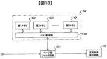
図12、図13を用いて本実施例の波面ずれ検出および補償手順を説明する。 The wavefront deviation detection and compensation procedure of this embodiment will be described with reference to FIGS.
図12にこの波面補償回路の構成図を示す。まず、光検出器225出力から計算された位相情報をページ間フィルタ回路1201に入力する。ページ間フィルタ回路1201は、入力された位相情報をメモリ1202のメモリ制御部1301に入力する。メモリ制御部1301は処理するページ順に第1メモリ1302から第Nメモリ1304まで順に位相情報を格納する。格納される位相情報は、古いページのものから順に新しいページのものに置き換える。また、メモリ制御部1301は第1メモリ1302から第Nメモリ1304までの位相情報全てもしくはその一部をページ間フィルタ回路1201に渡す。次にページ間フィルタ回路1201はメモリ制御部1301から入力された複数ページの同じ位置のピクセルの位相情報を平均し、波面ずれから生じる干渉縞(図10(a))を算出し波面ずれ検出回路102に入力する。以降の動作は実施例1と同様である。
FIG. 12 shows a configuration diagram of the wavefront compensation circuit. First, the phase information calculated from the output of the
第1メモリ1302から第Nメモリ1304に格納される位相情報はブック毎に初期化するのが良いが、異なるブックにおいてもオシレーター光230と回折光231の波面ずれの状態が変わらないようであれば初期化せずに処理してもよい。
The phase information stored in the
なお、本実施例では平均化の手法として複数ページの位相情報を別々のメモリに格納していたがこれに限定するものではなく、前のページの位相情報に新しいページの位相情報を加算し続けるような方法など、複数ページの位相情報を平均できれば他の方法を使用してもよい。また、あるブックで算出した補償量を他のブックに使用してもよい。 In this embodiment, the phase information of a plurality of pages is stored in separate memories as an averaging method. However, the present invention is not limited to this, and the phase information of a new page is continuously added to the phase information of the previous page. Other methods may be used as long as the phase information of a plurality of pages can be averaged. Further, the compensation amount calculated for a certain book may be used for another book.
以上の構成によれば、ホログラムにおける記録再生光学系においてオシレーター光と回折光の波面ずれ補償が可能になり、再生性能を改善することが可能となる。さらに、実施例1の低域通過フィルタで遮断されるような波面ずれに対しても、高精度の補償が可能となる。 According to the above configuration, it becomes possible to compensate for the wavefront deviation between the oscillator light and the diffracted light in the hologram recording / reproducing optical system, and it is possible to improve the reproducing performance. Furthermore, high-accuracy compensation is possible even for a wavefront shift that is blocked by the low-pass filter of the first embodiment.
本実施例が実施例1と異なるのは、波面ずれ検出および補償手順である。 This embodiment differs from the first embodiment in the wavefront deviation detection and compensation procedure.
波面ずれを正確に検出するため、ページ全面が同一の輝度および/もしくは位相を有するホワイトページによる調整を行うことを目的とする。 In order to accurately detect a wavefront deviation, an object is to perform adjustment with a white page having the same luminance and / or phase on the entire page.
図14、図15を用いて本実施例の波面ずれ検出および補償手順を説明する。 The wavefront deviation detection and compensation procedure of this embodiment will be described with reference to FIGS.
図14のフローは記録時における動作フローを示したものである。記録対象となる位置に光情報記録媒体1を移動し(1401)、ガルバノミラーを基準となる角度に動かし(1402)、ホワイトページを記録(1403)、その後は通常通りのページを順に記録する(1404)。これら1401から1404までの動作を記録が完了するまで繰り返す(1405)。以上の手順で各ブックにホワイトページを記録する。 The flow of FIG. 14 shows the operation flow at the time of recording. The optical information recording medium 1 is moved to a position to be recorded (1401), the galvanometer mirror is moved to a reference angle (1402), a white page is recorded (1403), and then the normal pages are sequentially recorded ( 1404). These operations from 1401 to 1404 are repeated until the recording is completed (1405). The white page is recorded in each book by the above procedure.
図15のフローは再生時における動作フローを示したものである。再生対象となる位置に光情報記録媒体1を移動し(1501)、ガルバノミラーを基準となる角度に動かし(1502)、ホワイトページを再生(1503)する。ここで、実施例1と同様の手順により、波面ずれ検出回路102、補償量算出回路103で波面ずれを打ち消す補償量を算出する(1504)。この補償量に基づいて空間光変調器228もしくは波面制御素子を制御することでオシレーター光と回折光の波面ずれを補償する(1505)。その後は記録ページを順に再生する(1506)。これら1501から1506までの動作を再生が完了するまで繰り返す(1507)。
The flow in FIG. 15 shows the operation flow during reproduction. The optical information recording medium 1 is moved to the position to be reproduced (1501), the galvanometer mirror is moved to a reference angle (1502), and the white page is reproduced (1503). Here, according to the same procedure as in the first embodiment, the wavefront
以上の例では、各ブックにホワイトページを記録したが、必ずしも各ブックに必要なわけではなく、複数ブックおきにホワイトページを記録してもよい。また参照光の角度変化によってオシレーター光と回折光の波面ずれ量が変化する場合などには、各ブック中に複数のホワイトページを記録してもよい。なお、再生時も全てのホワイトページで調整を実施する必要はなく、複数ブックおき、もしくはディスク挿入時のみで調整するなどの方法を採ってもよい。 In the above example, a white page is recorded in each book. However, it is not always necessary for each book, and a white page may be recorded every plural books. Further, when the amount of wavefront deviation between the oscillator light and the diffracted light changes due to the change in the angle of the reference light, a plurality of white pages may be recorded in each book. Note that it is not necessary to make adjustments for all white pages during playback, and a method of making adjustments only when a plurality of books or a disc is inserted may be employed.
さらに、ホワイトページとしてページ全面が同一の輝度のページを例に説明したが、全面でなく一部の領域としてもよい。 Furthermore, although the page having the same luminance as the white page has been described as an example, it may be a partial area instead of the entire page.
以上の手順によれば、ホログラムにおける記録再生光学系においてオシレーター光と回折光の波面ずれ補償が可能になり、再生性能を改善することが可能となる。さらに、実施例1の低域通過フィルタで遮断されるような波面ずれに対しても、高精度の補償が可能となる。 According to the above procedure, it becomes possible to compensate for the wavefront deviation between the oscillator light and the diffracted light in the hologram recording / reproducing optical system, and to improve the reproducing performance. Furthermore, high-accuracy compensation is possible even for a wavefront shift that is blocked by the low-pass filter of the first embodiment.
本実施例が実施例1と異なるのは、オシレーター光の生成方法である。 This embodiment is different from the first embodiment in the method of generating oscillator light.
図16、図17を用いて本実施例の波面ずれ検出および補償手順を説明する。 The wavefront deviation detection and compensation procedure of this embodiment will be described with reference to FIGS.
図16はピックアップ11の構成であり、実施例1と図16が相違するのは、オシレーター光用の空間光変調器228を空間光変調器212と兼用している点である。また図17は図16における光ビームの経路を図示したものであるが、図中の矢印はビームの光軸などを示しているわけではなく、単に要素の通過順序を示しているにすぎない。
FIG. 16 shows the configuration of the
光検出器225において回折光231と干渉させるオシレーター光230を生成するため、偏光方向変換素子204によって偏光方向が制御され、所望の光量が偏光ビームスプリッタ205を透過する。偏光ビームスプリッタ205を透過したオシレーター光230は、ビームエキスパンダ208によって光ビーム径を拡大された後、偏光ビームスプリッタ211を透過して空間光変調器212に入射される。空間光変調器212では、所定の基準位相に加えて、該基準位相に対して90度、180度、270度異なる少なくとも4つの位相をオシレーター光230に付加する。このためには空間光変調器212は記録時のページデータの各画素に対して少なくとも4つの画素でオーバーサンプリングする様に画素が配置される必要があるので、本実施例の場合においては記録時に4つの画素で1つの画素を表示しておくと都合がよい。位相が付加されたオシレーター光230は、偏光ビームスプリッタ211を反射し、リレーレンズ213を伝播、1/4波長板1601により円偏光になり、ハーフミラー1602に入射する。ハーフミラー1602を反射したオシレーター光230は、1/4波長板1601により直線偏光になり偏光ビームスプリッタ211を透過し、光検出器225に入射する。
In order to generate the
一方、参照光207の光路中に置かれた1/4波長板1603により円偏光で再生された回折光231は、対物レンズ215、ハーフミラー1602を透過し、1/4波長板1601により直線偏光になり偏光ビームスプリッタ211を透過し光検出器225に入射する。
On the other hand, the diffracted light 231 reproduced as circularly polarized light by the
次に、図17に示すように光検出器225出力から計算された位相情報をフィルタ回路101に入力し、波面ずれ検出回路102、補償量算出回路103を経て補償量を算出する。切替器1701出力は、再生時には補償量算出回路103出力を選択し、記録時には信号生成回路86出力を選択するように動作する。再生時に空間光変調器212では、所定の基準位相に加えて、該基準位相に対して少なくとも4つの位相をオシレーター光230に付加していたが、該基準位相を切替器1701出力である補償量とするように空間光変調器212を制御する。
Next, as shown in FIG. 17, the phase information calculated from the output of the
以上の例では、1/4波長板1601およびハーフミラー1602を、対物レンズ215とリレーレンズ213の間に配置していたが、リレーレンズ213と偏光ビームスプリッタ211の間に配置するなど、オシレーター光230が空間光変調器212を経由して光検出器225に入射できるのであればどこに配置してもよい。さらに、ハーフミラー1602を使用して説明したが、フォトニック結晶素子など偏光に応じて透過、反射を制御可能な素子のように、オシレーター光を反射、回折光を透過する素子であれば何を使用してもよい。
In the above example, the
以上の構成によれば、ホログラムにおける記録再生光学系においてオシレーター光と回折光の波面ずれ補償が可能になり、再生性能を改善することが可能となる。さらに、信号光用の空間光変調器と、オシレーター光用の空間光変調器を共用できることからコストを抑えることが可能となる。 According to the above configuration, it becomes possible to compensate for the wavefront deviation between the oscillator light and the diffracted light in the hologram recording / reproducing optical system, and it is possible to improve the reproducing performance. Furthermore, since the spatial light modulator for signal light and the spatial light modulator for oscillator light can be shared, the cost can be reduced.
なお、本発明は上記した実施例に限定されるものではなく、様々な変形例が含まれる。例えば、上記した実施例は本発明を分かりやすく説明するために詳細に説明したものであり、必ずしも説明した全ての構成を備えるものに限定されるものではない。また、ある実施例の構成の一部を他の実施例の構成に置き換えることが可能であり、また、ある実施例の構成に他の実施例の構成を加えることも可能である。また、各実施例の構成の一部について、他の構成の追加・削除・置換をすることが可能である。 In addition, this invention is not limited to an above-described Example, Various modifications are included. For example, the above-described embodiments have been described in detail for easy understanding of the present invention, and are not necessarily limited to those having all the configurations described. Further, a part of the configuration of one embodiment can be replaced with the configuration of another embodiment, and the configuration of another embodiment can be added to the configuration of one embodiment. Further, it is possible to add, delete, and replace other configurations for a part of the configuration of each embodiment.
また、上記の各構成、機能、処理部、処理手段等は、それらの一部又は全部を、例えば集積回路で設計する等によりハードウェアで実現してもよい。また、上記の各構成、機能等は、プロセッサがそれぞれの機能を実現するプログラムを解釈し、実行することによりソフトウェアで実現してもよい。各機能を実現するプログラム、テーブル、ファイル等の情報は、メモリや、ハードディスク、SSD(Solid State Drive)等の記録装置、または、ICカード、SDカード、DVD等の記録媒体に置くことができる。 Each of the above-described configurations, functions, processing units, processing means, and the like may be realized by hardware by designing a part or all of them with, for example, an integrated circuit. Each of the above-described configurations, functions, and the like may be realized by software by interpreting and executing a program that realizes each function by the processor. Information such as programs, tables, and files for realizing each function can be stored in a memory, a hard disk, a recording device such as an SSD (Solid State Drive), or a recording medium such as an IC card, an SD card, or a DVD.
また、制御線や情報線は説明上必要と考えられるものを示しており、製品上必ずしも全ての制御線や情報線を示しているとは限らない。実際には殆ど全ての構成が相互に接続されていると考えてもよい。 Further, the control lines and information lines indicate what is considered necessary for the explanation, and not all the control lines and information lines on the product are necessarily shown. Actually, it may be considered that almost all the components are connected to each other.
1・・・光情報記録媒体、10・・・光情報記録再生装置、11・・・ピックアップ、12・・・再生用参照光光学系、13・・・ディスクCure光学系、14・・・ディスク回転角度検出用光学系、50・・・回転モータ、81・・・アクセス制御回路、82・・・光源駆動回路、83・・・サーボ信号生成回路、84・・・サーボ制御回路、85・・・信号処理回路、86・・・信号生成回路、87・・・シャッタ制御回路、88・・・ディスク回転モータ制御回路、89・・・コントローラ、90・・・入出力制御回路、91・・・外部制御装置、101・・・フィルタ回路、102・・・波面ずれ検出回路、103・・・補償量算出回路、201・・・光源、202・・・コリメートレンズ、203・・・シャッタ、204・・・1/2波長板、205・・・偏光ビームスプリッタ、206・・・信号光、207・・・参照光、208・・・ビームエキスパンダ、209・・・偏光方向変換素子、210・・・偏光ビームスプリッタ、211・・・偏光ビームスプリッタ、212・・・空間光変調器、213・・・リレーレンズ、214・・・空間フィルタ、215・・・対物レンズ、216・・・偏光方向変換素子、217・・・ミラー、218・・・ミラー、219・・・ミラー、220・・・アクチュエータ、221・・・レンズ、222・・・レンズ、223・・・アクチュエータ、224・・・ミラー、225・・・光検出器、226・・・1/2波長板、227・・・ミラー、228・・・空間光変調器、229・・・無偏光性ビームスプリッタ、230・・・オシレーター光、231・・・回折光、250・・・光学素子、251・・・光学素子、1201・・・ページ間フィルタ回路、1202・・・メモリ、1301・・・メモリ制御部、1301・・・第1メモリ、1302・・・第2メモリ、1303・・・第Nメモリ、1601・・・1/4波長板、1602・・・ハーフミラー、1603・・・1/4波長板、1701・・・切替器
DESCRIPTION OF SYMBOLS 1 ... Optical information recording medium, 10 ... Optical information recording / reproducing apparatus, 11 ... Pickup, 12 ... Reference optical system for reproduction | regeneration, 13 ... Disc Cure optical system, 14 ... Disc Rotation angle detection optical system, 50... Rotation motor, 81... Access control circuit, 82... Light source drive circuit, 83 ... Servo signal generation circuit, 84.
Claims (13)
前記光記録媒体からの再生光と重ね合わせて干渉させるオシレーター光を生成するオシレーター光生成部と、
前記オシレーター光と前記再生光との間に所定の位相差を付加する位相変調部と、
前記オシレーター光と前記再生光とが重ね合わさった干渉光を検出する光検出部と、
前記光検出部出力から前記オシレーター光と前記再生光の波面ずれ量を検出する波面ずれ検出部と、
前記波面ずれ量から波面補償量を算出する補償量算出部と、を具備し、
前記波面補償量に基づいて前記位相変調部で付加する位相差を制御し、
前記波面ずれ検出部では、前記光検出部出力に対して低域通過フィルタを通した信号に基づいて波面ずれ量を検出する、
ことを特徴とする光情報記録再生装置。 In an optical information recording / reproducing apparatus for recording / reproducing information using light with respect to an optical recording medium,
An oscillator light generating unit that generates an oscillator light that overlaps and interferes with the reproduction light from the optical recording medium;
A phase modulator that adds a predetermined phase difference between the oscillator light and the reproduction light;
A light detection unit that detects interference light in which the oscillator light and the reproduction light are superimposed;
A wavefront deviation detector that detects the amount of wavefront deviation between the oscillator light and the reproduction light from the output of the light detector;
A compensation amount calculation unit for calculating a wavefront compensation amount from the wavefront deviation amount,
Control the phase difference added by the phase modulation unit based on the wavefront compensation amount ,
The wavefront deviation detection unit detects a wavefront deviation amount based on a signal that has passed through a low-pass filter with respect to the light detection unit output.
An optical information recording / reproducing apparatus.
前記波面ずれ検出部では、複数ページ分の前記光検出部出力に対して平滑化した信号に基づいて波面ずれ量を検出する、
ことを特徴とする光情報記録再生装置。 The optical information recording / reproducing apparatus according to claim 1.
The wavefront deviation detection unit detects a wavefront deviation amount based on a signal smoothed with respect to the light detection unit output for a plurality of pages.
An optical information recording / reproducing apparatus.
信号光に情報を付加するための信号光変調部を具備し、
前記信号光変調部出力の信号光と参照光とを干渉させ、得られた干渉縞をホログラムとして前記光記録媒体に記録することで情報の記録を行い、記録された前記光記録媒体を再生することで情報の再生を行うことを特徴とする光情報記録再生装置。 The optical information recording / reproducing apparatus according to claim 1.
A signal light modulator for adding information to the signal light,
The signal light output from the signal light modulation section interferes with the reference light, and the obtained interference fringes are recorded as a hologram on the optical recording medium to record information and reproduce the recorded optical recording medium An optical information recording / reproducing apparatus characterized in that information is reproduced.
記録時にページの全面もしくは一部の輝度および/もしくは位相が一様な基準ページを記録し、
再生時に前記基準ページに対して前記波面補償量を算出し、
前記基準ページの波面補償量に基づいて前記位相変調部で付加する位相差を制御する、
ことを特徴とする光情報記録再生装置。 The optical information recording / reproducing apparatus according to claim 3 .
Record a reference page with uniform brightness and / or phase on the entire page or part of the page when recording,
Calculate the wavefront compensation amount for the reference page during playback,
Control the phase difference added by the phase modulation unit based on the wavefront compensation amount of the reference page,
An optical information recording / reproducing apparatus.
前記信号光変調部と前記位相変調部を共用する、
ことを特徴とする光情報記録再生装置。 The optical information recording / reproducing apparatus according to claim 3 .
Sharing the signal light modulator and the phase modulator;
An optical information recording / reproducing apparatus.
前記光記録媒体からの再生光と重ね合わせて干渉させるオシレーター光を生成するオシレーター光生成ステップと、
前記オシレーター光と前記再生光との間に所定の位相差を付加する位相変調ステップと、
前記オシレーター光と前記再生光とが重ね合わさった干渉光を検出する光検出ステップと、
前記光検出ステップ結果から前記オシレーター光と前記再生光の波面ずれ量を検出する波面ずれ検出ステップと、
前記波面ずれ量から波面補償量を算出する補償量算出ステップと、
前記波面補償量に基づいて前記位相変調ステップで付加する位相差を制御するステップと、
前記波面ずれ検出ステップでは、前記光検出ステップ結果に対して低域通過フィルタを通した信号に基づいて波面ずれ量を検出する、
ことを特徴とする光情報記録再生方法。 In an optical information recording / reproducing method for recording / reproducing information using light on an optical recording medium,
An oscillator light generating step for generating an oscillator light that overlaps and interferes with the reproduction light from the optical recording medium;
A phase modulation step of adding a predetermined phase difference between the oscillator light and the reproduction light;
A light detection step of detecting interference light in which the oscillator light and the reproduction light are superimposed;
A wavefront deviation detection step for detecting a wavefront deviation amount of the oscillator light and the reproduction light from the light detection step result;
A compensation amount calculating step of calculating a wavefront compensation amount from the wavefront deviation amount;
Controlling the phase difference added in the phase modulation step based on the wavefront compensation amount ;
In the wavefront deviation detection step, a wavefront deviation amount is detected based on a signal that has passed through a low-pass filter for the light detection step result.
An optical information recording / reproducing method.
前記波面ずれ検出ステップでは、複数ページ分の前記光検出ステップ結果に対して平滑化した信号に基づいて波面ずれ量を検出する、
ことを特徴とする光情報記録再生方法。 The optical information recording / reproducing method according to claim 6 ,
In the wavefront deviation detection step, a wavefront deviation amount is detected based on a signal smoothed with respect to the light detection step result for a plurality of pages.
An optical information recording / reproducing method.
信号光に情報を付加するための信号光変調ステップを具備し、
前記信号光変調ステップ結果の信号光と参照光とを干渉させ、得られた干渉縞をホログラムとして前記光記録媒体に記録することで情報の記録を行い、記録された前記光記録媒体を再生することで情報の再生を行うことを特徴とする光情報記録再生方法。 The optical information recording / reproducing method according to claim 6 ,
A signal light modulation step for adding information to the signal light,
The signal light resulting from the signal light modulation step interferes with the reference light, and the obtained interference fringes are recorded as a hologram on the optical recording medium to record information, and the recorded optical recording medium is reproduced. An optical information recording / reproducing method characterized in that information is reproduced.
記録時にページの全面もしくは一部の輝度および/もしくは位相が一様な基準ページを記録し、
再生時に前記基準ページに対して前記波面補償量を算出し、
前記基準ページの波面補償量に基づいて前記位相変調ステップで付加する位相差を制御する、
ことを特徴とする光情報記録再生方法。 The optical information recording / reproducing method according to claim 8 ,
Record a reference page with uniform brightness and / or phase on the entire page or part of the page when recording,
Calculate the wavefront compensation amount for the reference page during playback,
Controlling the phase difference added in the phase modulation step based on the wavefront compensation amount of the reference page;
An optical information recording / reproducing method.
前記ホログラム記録媒体からの再生光と重ね合わせて干渉させるオシレーター光を生成するオシレーター光生成部と、
前記オシレーター光と前記再生光との間に所定の位相差を付加する位相変調部と、
前記オシレーター光と前記再生光とが重ね合わさった干渉光を検出する光検出部と、
前記光検出部出力から前記オシレーター光と前記再生光の波面ずれ量を検出する波面ずれ検出部と、
前記波面ずれ量から波面補償量を算出する補償量算出部と、を具備し、
前記波面補償量に基づいて前記位相変調部で付加する位相差を制御し、
前記波面ずれ検出部では、前記光検出部出力に対して低域通過フィルタを通した信号に基づいて波面ずれ量を検出する、
ことを特徴とする光情報再生装置。 In an optical information reproducing apparatus for reproducing information using light to an optical recording medium,
An oscillator light generating unit that generates oscillator light that overlaps and interferes with reproduction light from the hologram recording medium;
A phase modulator that adds a predetermined phase difference between the oscillator light and the reproduction light;
A light detection unit that detects interference light in which the oscillator light and the reproduction light are superimposed;
A wavefront deviation detector that detects the amount of wavefront deviation between the oscillator light and the reproduction light from the output of the light detector;
A compensation amount calculation unit for calculating a wavefront compensation amount from the wavefront deviation amount,
Control the phase difference added by the phase modulation unit based on the wavefront compensation amount ,
The wavefront deviation detection unit detects a wavefront deviation amount based on a signal that has passed through a low-pass filter with respect to the light detection unit output.
An optical information reproducing apparatus characterized by the above.
前記波面ずれ検出部では、複数ページ分の前記光検出部出力に対して平滑化した信号に基づいて波面ずれ量を検出する、
ことを特徴とする光情報再生装置。 The optical information reproducing apparatus according to claim 10 ,
The wavefront deviation detection unit detects a wavefront deviation amount based on a signal smoothed with respect to the light detection unit output for a plurality of pages.
An optical information reproducing apparatus characterized by the above.
参照光と信号光とを干渉させ、得られた干渉縞がホログラムとして記録された前記光記録媒体を再生することで情報の再生を行うことを特徴とする光情報再生装置。 The optical information reproducing apparatus according to claim 10 ,
An optical information reproducing apparatus for reproducing information by reproducing reference light and signal light, and reproducing the optical recording medium in which the obtained interference fringes are recorded as a hologram.
前記ホログラムの一部には、ページの全面もしくは一部の輝度および/もしくは位相が一様な基準ページが記録されており、
前記基準ページに対して前記波面補償量を算出し、
前記基準ページの波面補償量に基づいて前記位相変調部で付加する位相差を制御する、
ことを特徴とする光情報再生装置。 The optical information reproducing apparatus according to claim 12 ,
In a part of the hologram, a reference page having a uniform brightness and / or phase of the entire page or a part of the page is recorded,
Calculating the wavefront compensation amount for the reference page;
Control the phase difference added by the phase modulation unit based on the wavefront compensation amount of the reference page,
An optical information reproducing apparatus characterized by the above.
Priority Applications (3)
| Application Number | Priority Date | Filing Date | Title |
|---|---|---|---|
| JP2012138314A JP5802616B2 (en) | 2012-06-20 | 2012-06-20 | Optical information recording / reproducing apparatus and optical information recording / reproducing method |
| US13/874,551 US8873361B2 (en) | 2012-06-20 | 2013-05-01 | Optical information recording/reproducing apparatus and method |
| CN201310157886.6A CN103514908B (en) | 2012-06-20 | 2013-05-02 | Optical information recording/reproducing device and optical information recording/reproducing method |
Applications Claiming Priority (1)
| Application Number | Priority Date | Filing Date | Title |
|---|---|---|---|
| JP2012138314A JP5802616B2 (en) | 2012-06-20 | 2012-06-20 | Optical information recording / reproducing apparatus and optical information recording / reproducing method |
Publications (3)
| Publication Number | Publication Date |
|---|---|
| JP2014002823A JP2014002823A (en) | 2014-01-09 |
| JP2014002823A5 JP2014002823A5 (en) | 2014-10-30 |
| JP5802616B2 true JP5802616B2 (en) | 2015-10-28 |
Family
ID=49774350
Family Applications (1)
| Application Number | Title | Priority Date | Filing Date |
|---|---|---|---|
| JP2012138314A Expired - Fee Related JP5802616B2 (en) | 2012-06-20 | 2012-06-20 | Optical information recording / reproducing apparatus and optical information recording / reproducing method |
Country Status (3)
| Country | Link |
|---|---|
| US (1) | US8873361B2 (en) |
| JP (1) | JP5802616B2 (en) |
| CN (1) | CN103514908B (en) |
Families Citing this family (9)
| Publication number | Priority date | Publication date | Assignee | Title |
|---|---|---|---|---|
| KR101444279B1 (en) * | 2012-07-03 | 2014-11-03 | 도시바삼성스토리지테크놀러지코리아 주식회사 | optical pickup device and drive adopting the device |
| US9575464B2 (en) * | 2013-03-15 | 2017-02-21 | Vincent A Cassella | Non-mechanical digital/holographic wide angle control of one or more lasers beams |
| US9703260B2 (en) * | 2013-09-11 | 2017-07-11 | Akonia Holographics Llc | Methods and apparatus for coherent holographic data channels |
| JP2017519323A (en) * | 2014-04-29 | 2017-07-13 | アコニア ホログラフィックス、エルエルシー | Method and apparatus for coherent holographic data channel |
| WO2016020994A1 (en) * | 2014-08-06 | 2016-02-11 | 株式会社日立製作所 | Otical information recording device and optical information reproduction device |
| JP6297219B2 (en) * | 2015-06-03 | 2018-03-20 | 株式会社日立製作所 | Optical information recording apparatus, optical information recording method, optical information reproducing apparatus, and optical information reproducing method |
| JPWO2016208047A1 (en) * | 2015-06-26 | 2017-10-05 | 株式会社日立製作所 | Optical phase control device, optical phase control method, optical information recording / reproducing device, and optical information recording / reproducing method |
| WO2017042900A1 (en) * | 2015-09-09 | 2017-03-16 | 株式会社日立製作所 | Optical information recording device, optical information recording/reproducing device, and optical information recording method |
| CN111256956A (en) * | 2020-02-14 | 2020-06-09 | 上海慧希电子科技有限公司 | Wavefront measuring apparatus and wavefront measuring method |
Family Cites Families (11)
| Publication number | Priority date | Publication date | Assignee | Title |
|---|---|---|---|---|
| JP2004281026A (en) * | 2002-08-23 | 2004-10-07 | Matsushita Electric Ind Co Ltd | Optical pickup head device, optical information device, and optical information reproducing method |
| US7092133B2 (en) | 2003-03-10 | 2006-08-15 | Inphase Technologies, Inc. | Polytopic multiplex holography |
| JP2006090855A (en) * | 2004-09-24 | 2006-04-06 | Olympus Corp | Interferometer and method of measuring interference fringe |
| JP4558673B2 (en) * | 2006-04-27 | 2010-10-06 | 日本放送協会 | Hologram reproduction wavefront correction method and apparatus |
| JP4564948B2 (en) * | 2006-09-11 | 2010-10-20 | 株式会社日立製作所 | Optical information detection method, optical head, and optical disc apparatus |
| JP4524689B2 (en) * | 2007-02-20 | 2010-08-18 | ソニー株式会社 | Hologram reproducing apparatus, hologram reproducing method, and phase modulation element |
| JP2009015944A (en) * | 2007-07-03 | 2009-01-22 | Hitachi Ltd | Optical disk device |
| JP2009146542A (en) * | 2007-12-17 | 2009-07-02 | Toshiba Corp | Optical information recording apparatus and method |
| JP2011238311A (en) * | 2010-05-10 | 2011-11-24 | Hitachi Consumer Electronics Co Ltd | Optical information reproducing device, optical information recording device, and optical information recording/reproducing device |
| JP5358530B2 (en) | 2010-07-28 | 2013-12-04 | 日立コンシューマエレクトロニクス株式会社 | Optical information recording / reproducing apparatus and reproducing apparatus |
| JP5753768B2 (en) * | 2011-11-18 | 2015-07-22 | 日立コンシューマエレクトロニクス株式会社 | Optical information recording apparatus, optical information reproducing apparatus, optical information recording / reproducing apparatus, optical information recording method, optical information reproducing method, and optical information recording / reproducing method |
-
2012
- 2012-06-20 JP JP2012138314A patent/JP5802616B2/en not_active Expired - Fee Related
-
2013
- 2013-05-01 US US13/874,551 patent/US8873361B2/en not_active Expired - Fee Related
- 2013-05-02 CN CN201310157886.6A patent/CN103514908B/en not_active Expired - Fee Related
Also Published As
| Publication number | Publication date |
|---|---|
| JP2014002823A (en) | 2014-01-09 |
| US8873361B2 (en) | 2014-10-28 |
| US20130343171A1 (en) | 2013-12-26 |
| CN103514908B (en) | 2016-04-27 |
| CN103514908A (en) | 2014-01-15 |
Similar Documents
| Publication | Publication Date | Title |
|---|---|---|
| JP5802616B2 (en) | Optical information recording / reproducing apparatus and optical information recording / reproducing method | |
| JP5358530B2 (en) | Optical information recording / reproducing apparatus and reproducing apparatus | |
| JP5753768B2 (en) | Optical information recording apparatus, optical information reproducing apparatus, optical information recording / reproducing apparatus, optical information recording method, optical information reproducing method, and optical information recording / reproducing method | |
| JP2011227967A (en) | Reproduction device and reproduction method | |
| JP2008226433A (en) | Optical pickup, and optical information reproducing apparatus and optical information recording and reproducing apparatus using the optical pickup | |
| JP5677272B2 (en) | Optical information recording / reproducing apparatus, optical information reproducing apparatus, optical information recording / reproducing method, and optical information reproducing method | |
| JP2014010859A (en) | Method and device for recording and reproducing optical information | |
| JP5753767B2 (en) | Optical information recording / reproducing apparatus, optical information recording / reproducing method, and optical information recording medium | |
| JP5868494B2 (en) | Optical information recording / reproducing apparatus, optical information recording / reproducing method, and reproducing apparatus | |
| JP5557787B2 (en) | Optical information reproducing apparatus, optical information recording / reproducing apparatus | |
| JP5517912B2 (en) | Optical information recording / reproducing method and optical information recording / reproducing apparatus | |
| WO2014083619A1 (en) | Optical information recording and playback device and optical information recording and playback method | |
| WO2014091531A1 (en) | Optical information reproduction device and optical information reproduction method | |
| JP5953284B2 (en) | Optical information recording medium, optical information recording apparatus, optical information recording method, optical information reproducing apparatus, and optical information reproducing method. | |
| JP5414861B2 (en) | Optical information recording apparatus, optical information recording method, optical information recording / reproducing apparatus, and optical information recording / reproducing method | |
| JP5542739B2 (en) | Holographic memory reproducing apparatus and holographic memory reproducing method | |
| WO2015083246A1 (en) | Optical information reproduction device and optical information reproduction method | |
| WO2016163312A1 (en) | Optical information reproduction device and optical information reproduction method | |
| JP6078634B2 (en) | Optical information reproducing apparatus and optical information recording / reproducing apparatus | |
| WO2016020994A1 (en) | Otical information recording device and optical information reproduction device | |
| WO2016009546A1 (en) | Optical information recording/playback device, optical information playback device, and optical information playback method | |
| JP2015060613A (en) | Optical information recording device and optical information recording method | |
| JP2015082327A (en) | Optical information reproduction apparatus, optical information reproduction method, and optical information recording method | |
| JPWO2014167620A1 (en) | Optical information reproducing apparatus and optical information reproducing method | |
| WO2013175526A1 (en) | Optical information reproduction device, and optical information reproduction method |
Legal Events
| Date | Code | Title | Description |
|---|---|---|---|
| A521 | Request for written amendment filed |
Free format text: JAPANESE INTERMEDIATE CODE: A523 Effective date: 20140912 |
|
| A621 | Written request for application examination |
Free format text: JAPANESE INTERMEDIATE CODE: A621 Effective date: 20140912 |
|
| A521 | Request for written amendment filed |
Free format text: JAPANESE INTERMEDIATE CODE: A523 Effective date: 20140912 |
|
| A977 | Report on retrieval |
Free format text: JAPANESE INTERMEDIATE CODE: A971007 Effective date: 20150113 |
|
| A131 | Notification of reasons for refusal |
Free format text: JAPANESE INTERMEDIATE CODE: A131 Effective date: 20150120 |
|
| A521 | Request for written amendment filed |
Free format text: JAPANESE INTERMEDIATE CODE: A523 Effective date: 20150317 |
|
| TRDD | Decision of grant or rejection written | ||
| A01 | Written decision to grant a patent or to grant a registration (utility model) |
Free format text: JAPANESE INTERMEDIATE CODE: A01 Effective date: 20150804 |
|
| A61 | First payment of annual fees (during grant procedure) |
Free format text: JAPANESE INTERMEDIATE CODE: A61 Effective date: 20150831 |
|
| R150 | Certificate of patent or registration of utility model |
Ref document number: 5802616 Country of ref document: JP Free format text: JAPANESE INTERMEDIATE CODE: R150 |
|
| LAPS | Cancellation because of no payment of annual fees |