JP5784607B2 - Ultrasonic imaging apparatus and three-dimensional image display method - Google Patents
Ultrasonic imaging apparatus and three-dimensional image display method Download PDFInfo
- Publication number
- JP5784607B2 JP5784607B2 JP2012527662A JP2012527662A JP5784607B2 JP 5784607 B2 JP5784607 B2 JP 5784607B2 JP 2012527662 A JP2012527662 A JP 2012527662A JP 2012527662 A JP2012527662 A JP 2012527662A JP 5784607 B2 JP5784607 B2 JP 5784607B2
- Authority
- JP
- Japan
- Prior art keywords
- ultrasonic
- image
- ultrasonic probe
- dimensional image
- probe
- Prior art date
- Legal status (The legal status is an assumption and is not a legal conclusion. Google has not performed a legal analysis and makes no representation as to the accuracy of the status listed.)
- Active
Links
Images


Classifications
-
- G—PHYSICS
- G06—COMPUTING; CALCULATING OR COUNTING
- G06T—IMAGE DATA PROCESSING OR GENERATION, IN GENERAL
- G06T15/00—3D [Three Dimensional] image rendering
-
- A—HUMAN NECESSITIES
- A61—MEDICAL OR VETERINARY SCIENCE; HYGIENE
- A61B—DIAGNOSIS; SURGERY; IDENTIFICATION
- A61B8/00—Diagnosis using ultrasonic, sonic or infrasonic waves
- A61B8/13—Tomography
- A61B8/14—Echo-tomography
-
- A—HUMAN NECESSITIES
- A61—MEDICAL OR VETERINARY SCIENCE; HYGIENE
- A61B—DIAGNOSIS; SURGERY; IDENTIFICATION
- A61B8/00—Diagnosis using ultrasonic, sonic or infrasonic waves
- A61B8/42—Details of probe positioning or probe attachment to the patient
-
- A—HUMAN NECESSITIES
- A61—MEDICAL OR VETERINARY SCIENCE; HYGIENE
- A61B—DIAGNOSIS; SURGERY; IDENTIFICATION
- A61B8/00—Diagnosis using ultrasonic, sonic or infrasonic waves
- A61B8/42—Details of probe positioning or probe attachment to the patient
- A61B8/4245—Details of probe positioning or probe attachment to the patient involving determining the position of the probe, e.g. with respect to an external reference frame or to the patient
- A61B8/4263—Details of probe positioning or probe attachment to the patient involving determining the position of the probe, e.g. with respect to an external reference frame or to the patient using sensors not mounted on the probe, e.g. mounted on an external reference frame
-
- A—HUMAN NECESSITIES
- A61—MEDICAL OR VETERINARY SCIENCE; HYGIENE
- A61B—DIAGNOSIS; SURGERY; IDENTIFICATION
- A61B8/00—Diagnosis using ultrasonic, sonic or infrasonic waves
- A61B8/46—Ultrasonic, sonic or infrasonic diagnostic devices with special arrangements for interfacing with the operator or the patient
- A61B8/461—Displaying means of special interest
- A61B8/463—Displaying means of special interest characterised by displaying multiple images or images and diagnostic data on one display
-
- A—HUMAN NECESSITIES
- A61—MEDICAL OR VETERINARY SCIENCE; HYGIENE
- A61B—DIAGNOSIS; SURGERY; IDENTIFICATION
- A61B8/00—Diagnosis using ultrasonic, sonic or infrasonic waves
- A61B8/46—Ultrasonic, sonic or infrasonic diagnostic devices with special arrangements for interfacing with the operator or the patient
- A61B8/461—Displaying means of special interest
- A61B8/466—Displaying means of special interest adapted to display 3D data
-
- A—HUMAN NECESSITIES
- A61—MEDICAL OR VETERINARY SCIENCE; HYGIENE
- A61B—DIAGNOSIS; SURGERY; IDENTIFICATION
- A61B8/00—Diagnosis using ultrasonic, sonic or infrasonic waves
- A61B8/48—Diagnostic techniques
- A61B8/483—Diagnostic techniques involving the acquisition of a 3D volume of data
-
- G—PHYSICS
- G01—MEASURING; TESTING
- G01S—RADIO DIRECTION-FINDING; RADIO NAVIGATION; DETERMINING DISTANCE OR VELOCITY BY USE OF RADIO WAVES; LOCATING OR PRESENCE-DETECTING BY USE OF THE REFLECTION OR RERADIATION OF RADIO WAVES; ANALOGOUS ARRANGEMENTS USING OTHER WAVES
- G01S15/00—Systems using the reflection or reradiation of acoustic waves, e.g. sonar systems
- G01S15/88—Sonar systems specially adapted for specific applications
- G01S15/89—Sonar systems specially adapted for specific applications for mapping or imaging
- G01S15/8906—Short-range imaging systems; Acoustic microscope systems using pulse-echo techniques
- G01S15/8934—Short-range imaging systems; Acoustic microscope systems using pulse-echo techniques using a dynamic transducer configuration
- G01S15/8936—Short-range imaging systems; Acoustic microscope systems using pulse-echo techniques using a dynamic transducer configuration using transducers mounted for mechanical movement in three dimensions
-
- G—PHYSICS
- G01—MEASURING; TESTING
- G01S—RADIO DIRECTION-FINDING; RADIO NAVIGATION; DETERMINING DISTANCE OR VELOCITY BY USE OF RADIO WAVES; LOCATING OR PRESENCE-DETECTING BY USE OF THE REFLECTION OR RERADIATION OF RADIO WAVES; ANALOGOUS ARRANGEMENTS USING OTHER WAVES
- G01S15/00—Systems using the reflection or reradiation of acoustic waves, e.g. sonar systems
- G01S15/88—Sonar systems specially adapted for specific applications
- G01S15/89—Sonar systems specially adapted for specific applications for mapping or imaging
- G01S15/8906—Short-range imaging systems; Acoustic microscope systems using pulse-echo techniques
- G01S15/8993—Three dimensional imaging systems
-
- G—PHYSICS
- G01—MEASURING; TESTING
- G01S—RADIO DIRECTION-FINDING; RADIO NAVIGATION; DETERMINING DISTANCE OR VELOCITY BY USE OF RADIO WAVES; LOCATING OR PRESENCE-DETECTING BY USE OF THE REFLECTION OR RERADIATION OF RADIO WAVES; ANALOGOUS ARRANGEMENTS USING OTHER WAVES
- G01S7/00—Details of systems according to groups G01S13/00, G01S15/00, G01S17/00
- G01S7/52—Details of systems according to groups G01S13/00, G01S15/00, G01S17/00 of systems according to group G01S15/00
- G01S7/52017—Details of systems according to groups G01S13/00, G01S15/00, G01S17/00 of systems according to group G01S15/00 particularly adapted to short-range imaging
- G01S7/52053—Display arrangements
- G01S7/52057—Cathode ray tube displays
- G01S7/52073—Production of cursor lines, markers or indicia by electronic means
-
- G—PHYSICS
- G01—MEASURING; TESTING
- G01S—RADIO DIRECTION-FINDING; RADIO NAVIGATION; DETERMINING DISTANCE OR VELOCITY BY USE OF RADIO WAVES; LOCATING OR PRESENCE-DETECTING BY USE OF THE REFLECTION OR RERADIATION OF RADIO WAVES; ANALOGOUS ARRANGEMENTS USING OTHER WAVES
- G01S7/00—Details of systems according to groups G01S13/00, G01S15/00, G01S17/00
- G01S7/52—Details of systems according to groups G01S13/00, G01S15/00, G01S17/00 of systems according to group G01S15/00
- G01S7/52017—Details of systems according to groups G01S13/00, G01S15/00, G01S17/00 of systems according to group G01S15/00 particularly adapted to short-range imaging
- G01S7/52053—Display arrangements
- G01S7/52057—Cathode ray tube displays
- G01S7/52074—Composite displays, e.g. split-screen displays; Combination of multiple images or of images and alphanumeric tabular information
-
- A—HUMAN NECESSITIES
- A61—MEDICAL OR VETERINARY SCIENCE; HYGIENE
- A61B—DIAGNOSIS; SURGERY; IDENTIFICATION
- A61B8/00—Diagnosis using ultrasonic, sonic or infrasonic waves
- A61B8/46—Ultrasonic, sonic or infrasonic diagnostic devices with special arrangements for interfacing with the operator or the patient
- A61B8/467—Ultrasonic, sonic or infrasonic diagnostic devices with special arrangements for interfacing with the operator or the patient characterised by special input means
- A61B8/469—Ultrasonic, sonic or infrasonic diagnostic devices with special arrangements for interfacing with the operator or the patient characterised by special input means for selection of a region of interest
Description
本発明は、超音波探触子を用いて検査対象を画像化する超音波画像装置に係り、特に、操作性に優れ、操作者が求める画像をそのまま表示可能な超音波画像装置と超音波画像を用いた三次元画像表示方法に関する。 The present invention relates to an ultrasonic imaging apparatus that images an inspection object using an ultrasonic probe, and in particular, an ultrasonic imaging apparatus and an ultrasonic image that are excellent in operability and can display an image requested by an operator as it is. The present invention relates to a method for displaying a three-dimensional image using.
超音波画像装置は、超音波を発信するとともに受信するトランスデューサを超音波探触子として用い検査対象の内部を画像化するものであって、非侵襲的な検査装置として診断に多用されている。超音波探触子は、一般的に複数の振動素子を一方向に配列させた構造を有し、検査対象の表面に接触させた状態でこれら複数の振動素子を順次駆動する。超音波画像装置は、複数の超音波振動素子が順次駆動されることによって、超音波ビームを検査対象の内部に送り、検査対象の内部からの反射エコー信号を計測する。超音波画像装置は、検査対象の内部からの反射エコー信号を計測することにより、素子配列を含み検査対象表面とほぼ直交する断面の情報(断層像)を得る。 An ultrasonic imaging apparatus uses a transducer that transmits and receives ultrasonic waves as an ultrasonic probe to image the inside of an inspection object, and is often used for diagnosis as a non-invasive inspection apparatus. The ultrasonic probe generally has a structure in which a plurality of vibration elements are arranged in one direction, and sequentially drives the plurality of vibration elements while being in contact with the surface of the inspection object. The ultrasonic imaging apparatus sequentially drives a plurality of ultrasonic vibration elements to send an ultrasonic beam to the inside of the inspection target and measure a reflected echo signal from the inside of the inspection target. The ultrasonic imaging apparatus obtains information (tomographic image) of a cross section including the element array and substantially orthogonal to the surface of the inspection object by measuring a reflected echo signal from the inside of the inspection object.
超音波画像装置で取得された断層像は、操作者が手動で動かす超音波探触子からの情報であるため、その位置情報は相対的なものである。従って超音波探触子の位置情報を記録し、また操作者に知らせる手段が必要となる。 Since the tomographic image acquired by the ultrasonic imaging apparatus is information from the ultrasonic probe that is manually moved by the operator, the position information is relative. Therefore, a means for recording the position information of the ultrasonic probe and notifying the operator is required.
従来の超音波画像装置では、モニターに表示される断層像が超音波探触子の表面、裏面の何れかから、超音波探触子のどの素子配列から得られた断層像であるかを認識できるようにするため、超音波探触子には突起や溝等の方向マーカが設けられると共に、表示画面には方向マーカに対応するオリエンテーションマークが画像に重ねて表示される。 In conventional ultrasonic imaging devices, the tomographic image displayed on the monitor is recognized from the front or back surface of the ultrasonic probe from which element arrangement of the ultrasonic probe In order to make this possible, the ultrasonic probe is provided with direction markers such as protrusions and grooves, and an orientation mark corresponding to the direction marker is displayed on the display screen so as to overlap the image.
オリエンテーションマークは、超音波探触子の方向マーカが設けられる面を表面として、超音波探触子の方向マーカを、操作者から見て右側となるように持って撮影した場合、操作者側から見た断層像を表示させるように視線方向を設定すると、断層像の右側(方向マーカと同じ右側)に表示される。 The orientation mark is taken from the operator's side when the ultrasonic probe's direction marker is on the right side when viewed from the operator with the surface on which the ultrasonic probe's direction marker is provided as the surface. When the line-of-sight direction is set to display the viewed tomographic image, it is displayed on the right side of the tomographic image (the same right side as the direction marker).
一方、オリエンテーションマークは、超音波探触子の方向マーカが設けられない面を裏面として、超音波探触子の方向マーカを、操作者から見て右側となるように持って撮影した場合、操作者側から見た断層像を表示させるように視線方向を設定すると、断層像の左側(方向マーカと反対の左側)に表示される。 On the other hand, the orientation mark is operated when the ultrasonic probe direction marker is photographed so that it is on the right side when viewed from the operator, with the surface on which the ultrasonic probe direction marker is not provided on the back side. When the line-of-sight direction is set so that a tomographic image viewed from the person side is displayed, it is displayed on the left side of the tomographic image (the left side opposite to the direction marker).
結局、超音波探触子の表面から裏面へ、あるいは裏面から表面への切替は視線方向を切り替えることと同じ意味となる。 After all, switching from the front surface to the back surface of the ultrasonic probe or from the back surface to the front surface has the same meaning as switching the line-of-sight direction.
操作者は、超音波探触子の方向マーカの配置と、画面上のオリエンテーションマークの配置が同じであるか否かを見れば、断層像がどちらから見た断層像か、つまり視線方向の向きを知ることができ、また視線方向の切り替えが可能である。 If the operator sees whether the placement of the ultrasound direction marker and the orientation mark on the screen are the same, the operator sees the tomogram from which side, ie, the direction of the line of sight Can be known, and the direction of the line of sight can be switched.
また、画面上に、被検者の検査部位や姿勢を示すボディマークを表示するとともに、超音波探触子の位置及び方向を表すプローブマークをボディマーク上に表示することが一般的に行われている。 In addition, it is common practice to display a body mark indicating the examination site and posture of the subject on the screen and a probe mark indicating the position and direction of the ultrasonic probe on the body mark. ing.
さらに、位置情報センサを用いて、実空間における超音波探触子の位置を検出し、自動的に被検者の体勢に合わせたボディマークの表示、プローブマークの位置及び方向表示を行う超音波画像装置も提案されている(特許文献1)。 In addition, the position information sensor is used to detect the position of the ultrasonic probe in real space and automatically display the body mark according to the posture of the subject and the position and direction of the probe mark. An image device has also been proposed (Patent Document 1).
一方、3次元画像を取得する機能を備えた超音波画像装置が実用化されている(例えば、特許文献2)。 On the other hand, an ultrasonic imaging apparatus having a function of acquiring a three-dimensional image has been put into practical use (for example, Patent Document 2).
特許文献2等の3次元画像の取得手法には、大きく分けて二つある。3次元画像の取得手法の一つは、超音波探触子の素子配列(超音波の発信源)を中心軸として揺動させる方法である。3次元画像の取得手法の他の一つは、超音波探触子を素子配列と直交する方向にアクチュエータ或いは手動で平行移動させる方法である。 There are roughly two methods for acquiring a three-dimensional image such as Patent Document 2. One of the three-dimensional image acquisition methods is a method of swinging around the element array (ultrasound transmission source) of the ultrasonic probe as a central axis. Another method for acquiring a three-dimensional image is a method in which the ultrasonic probe is translated by an actuator or manually in a direction orthogonal to the element array.
3次元画像の取得手法他の一つは、3次元画像を取得する場合、操作者は2次元画像(断層像)上で関心領域を設定し、断層面(XY面)のサイズと方向を決め、Z方向の収集距離、収集時間、収集ピッチ等を設定することでZ方向のサイズを決め画像データの収集をすることが一般的である。 Another way to acquire 3D images is to acquire a 3D image.The operator sets the region of interest on the 2D image (tomographic image) and determines the size and direction of the tomographic plane (XY plane). Generally, image data is collected by determining the size in the Z direction by setting the collection distance, collection time, collection pitch, and the like in the Z direction.
Z方向すなわち超音波探触子を移動する方向は、超音波探触子の走査面をXY面に対し正負2つの向き(+Z方向と−Z方向)がある。超音波探触子の走査面の向きは一方の向きに固定されているか、超音波探触子の方向マーカの位置を基準に決められる2つの向きのいずれかを選択するようになっている。 The Z direction, that is, the direction in which the ultrasonic probe is moved, has two directions (+ Z direction and −Z direction) on the scanning plane of the ultrasonic probe with respect to the XY plane. The direction of the scanning surface of the ultrasonic probe is fixed in one direction, or one of two directions determined based on the position of the direction marker of the ultrasonic probe is selected.
例えば、操作者が、超音波探触子の方向マーカを右側になるように持ったとき、手前から奥へ移動させる方向が+Z方向、奥から手前へ移動させる方向が−Z方向と決められている。操作者はこのような設定を行った後、設定した方向に超音波探触子を移動させながら撮影を行う。 For example, when the operator holds the ultrasonic probe direction marker on the right side, the direction to move from the front to the back is determined as the + Z direction, and the direction to move from the back to the front is determined as the -Z direction. Yes. After making such settings, the operator performs shooting while moving the ultrasonic probe in the set direction.
断層像は超音波探触子の移動の方向の各位置で取得される。超音波画像装置は移動方向に合わせて、これら断層像を2次元画像フレームのメモリに格納し、3次元画像(立体画像)を構築する。構築された3次元画像は断層像とともに表示画面に表示される。 A tomographic image is acquired at each position in the direction of movement of the ultrasound probe. The ultrasonic imaging apparatus stores these tomographic images in a memory of a two-dimensional image frame in accordance with the moving direction, and constructs a three-dimensional image (stereoscopic image). The constructed 3D image is displayed on the display screen together with the tomographic image.
上述したように超音波探触子を移動させて3次元画像用のデータを取得する場合、操作者は(1)超音波探触子の方向マークの確認すなわち視線方向の設定、(2)移動方向の設定(定義)、を行う必要がある。 As described above, when acquiring the data for 3D images by moving the ultrasound probe, the operator (1) confirms the direction mark of the ultrasound probe, that is, sets the line-of-sight direction, and (2) moves. It is necessary to set (define) the direction.
しかしながら、操作者が診断を行っている最中には、被検者の体勢変更や関心領域の移動等に伴い超音波探触子の当て方や持ち方を変更する場合があり、その場合、視線方向と移動方向の定義が逆になる可能性がある。 However, while the operator is making a diagnosis, the method of applying and holding the ultrasonic probe may be changed along with the change in the posture of the subject or the movement of the region of interest. The definition of the gaze direction and the moving direction may be reversed.
また、操作者が超音波探触子を被検者の体内に挿入する検査等の場合には、視線方向の設定自体が困難な場合もある。操作者の意図する視線方向と構築された3次元画像の表示の向きとが逆になる可能性がある。 In addition, in the case of an examination in which the operator inserts an ultrasonic probe into the body of the subject, setting the line-of-sight direction may be difficult. There is a possibility that the gaze direction intended by the operator and the display direction of the constructed three-dimensional image are reversed.
例えば、図10に示す位置関係が定義されている場合、超音波探触子を方向マーカが左側となるように持ち、視線方向が右側に持った場合と逆になっている状態で、移動方向の設定(+Z方向或いは−Z方向の設定)をした場合、超音波画像装置は、設定された移動方向に従って3次元画像用の断層像を収集するため、構築された3次元画像は操作者からは鏡像となって表示される。操作者は鏡像となった表示を実像と誤認すれば、表示画像の誤診断につながるおそれがある。 For example, in the case where the positional relationship shown in FIG. 10 is defined, the moving direction in the state where the ultrasonic probe is held so that the direction marker is on the left side and the line-of-sight direction is on the right side is reversed. When setting (+ Z direction or -Z direction setting), the ultrasonic imaging apparatus collects tomographic images for 3D images according to the set moving direction, so the constructed 3D image is received from the operator. Is displayed as a mirror image. If the operator misidentifies the mirrored display as a real image, there is a risk of misdiagnosis of the display image.
本発明は、表示画像の操作者の方向誤認等を防止することが可能な超音波画像装置を提供することを目的とする。 An object of the present invention is to provide an ultrasonic imaging apparatus capable of preventing misdirection of the operator of a display image.
上記目的を達成するため本発明の超音波画像装置は、画面に表示された画像を基準とする超音波探触子移動方向の設定機能及び、その方向に合わせた3次元画像構築および3次元画像表示機能を備えたものである。 In order to achieve the above object, the ultrasonic imaging apparatus of the present invention has a function of setting an ultrasonic probe moving direction based on an image displayed on a screen, and a three-dimensional image construction and a three-dimensional image according to the direction. It has a display function.
すなわち、本発明の超音波画像装置は、超音波探触子と、検査対象に前記超音波探触子を介して超音波信号を送受信させる送受信回路と、受信した超音波信号を用いて検査対象の超音波断層像を構成する画像構成部と、前記超音波断層像を表示する表示部と、前記画像構成部および前記表示部を制御する制御部とを備えた超音波画像装置であって、前記超音波探触子を前記超音波断層像と交差する方向に移動したときに取得される複数枚の超音波断層像を用いて3次元画像を構築する3次元画像構築部と、前記表示部の画面に表示された超音波断層像を基準として、それと交差する第1の方向と、当該第1の方向と反対向きの第2の方向のいずれかの超音波探触子移動方向を設定する超音波探触子移動方向設定部と、を備え、前記制御部は、前記超音波探触子移動方向設定部によって設定された超音波探触子の移動方向に応じて、前記3次元画像構築部において構築される3次元画像における複数枚の超音波断層像の配置順序を制御することを特徴とする。
That is, the ultrasonic imaging apparatus of the present invention includes an ultrasonic probe, a transmission / reception circuit that causes the inspection target to transmit and receive an ultrasonic signal via the ultrasonic probe, and an inspection target using the received ultrasonic signal. An ultrasonic imaging apparatus comprising: an image forming unit that forms an ultrasonic tomographic image; a display unit that displays the ultrasonic tomographic image; and a control unit that controls the image forming unit and the display unit, A three-dimensional image constructing unit that constructs a three-dimensional image using a plurality of ultrasonic tomographic images acquired when the ultrasonic probe is moved in a direction intersecting the ultrasonic tomographic image; and the display unit based on the ultrasonic tomographic image displayed on the screen, at the same settings and the first direction intersecting, one of the ultrasonic feeler KoUtsuri movement direction of the second direction between the first direction opposite An ultrasonic probe movement direction setting unit, and the control unit The arrangement order of multiple ultrasonic tomographic images in the 3D image constructed in the 3D image construction unit is controlled according to the movement direction of the ultrasound probe set by the wave probe movement direction setting unit It is characterized by doing.
また、本発明の三次元画像表示方法は、検査対象に超音波探触子を介して超音波信号を送受信させるステップと、受信した超音波信号を用いて検査対象の超音波断層像を構成するステップと、前記超音波断層像を表示するステップと、を含む三次元画像表示方法であって、前記超音波探触子を前記超音波断層像と交差する方向に移動したときに取得される複数枚の超音波断層像を用いて3次元画像を構築するステップと、画面に表示された超音波断層像を基準として、それと交差する第1の方向と、当該第1の方向と反対向きの第2の方向のいずれかの超音波探触子移動方向を設定するステップと、前記設定された超音波探触子移動方向に応じて、前記構築される3次元画像における複数枚の超音波断層像の配置順序を制御するステップと、前記設定された超音波探触子の移動方向に応じて、前記構築される3次元画像における複数枚の超音波断層像の配置順序を制御するステップを含むことを特徴とする。 Further, the 3D image display method of the present invention includes a step of transmitting and receiving an ultrasonic signal to an inspection object via an ultrasonic probe, and constructing an ultrasonic tomographic image of the inspection object using the received ultrasonic signal. A three- dimensional image display method comprising: a step; and a step of displaying the ultrasonic tomographic image, wherein a plurality of information is acquired when the ultrasonic probe is moved in a direction intersecting the ultrasonic tomographic image. A step of constructing a three-dimensional image using one ultrasonic tomographic image, a first direction intersecting with the ultrasonic tomographic image displayed on the screen, and a first direction opposite to the first direction. and setting one of the ultrasonic feeler KoUtsuri movement direction of the two directions, depending on the set ultrasonic probe moving direction, a plurality of ultrasonic tomographic the three-dimensional image the constructed A step of controlling the arrangement order of the images; Depending on the moving direction of the ultrasonic probe, characterized in that it comprises the step of controlling the arrangement order of a plurality of ultrasonic tomographic image in the three-dimensional image the is built.
本発明によれば、表示画像の操作者の方向誤認等を防止することが可能な超音波画像装置を提供することができるという効果を奏する。 According to the present invention, there is an effect that it is possible to provide an ultrasonic imaging apparatus capable of preventing misdirection of the operator of the display image.
以下、本発明の超音波画像装置の実施の形態を、図面を参照して説明する。 Hereinafter, embodiments of the ultrasonic imaging apparatus of the present invention will be described with reference to the drawings.
<第1の実施形態>
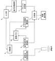
本実施の形態の超音波画像装置の全体概要を図1に示す。この超音波画像装置は、検査対象(図示省略)に超音波ビームを送り出すとともに検体対象からの反射エコーを受信する超音波探触子1と、超音波探触子1に超音波信号を送信するとともに超音波探触子1からの反射エコー信号を受信する超音波送受信回路2と、反射エコー信号を超音波画像に再構成する超音波信号変換部3と、超音波信号変換部3で作成された超音波画像を表示する画像表示部4と、超音波送受信回路2および超音波信号変換部3を含む装置の各部を制御する制御部5とを備えている。制御部5は、入力部6として、操作者からの入力を受け付けるためのキーやトラックボールなどを備えた操作パネル及び入力に必要なGUIなどを表示する表示部が備えられている。入力部6の表示部は、画像表示部4が兼ねることも可能である。<First Embodiment>
An overall outline of the ultrasonic imaging apparatus of the present embodiment is shown in FIG. This ultrasonic imaging apparatus transmits an ultrasonic signal to an
さらにこの超音波画像装置は、超音波画像とともに表示されるオリエンテーション画像を収納するグラフィック表示部7(画像記憶部)と、グラフィック表示部7のオリエンテーション画像を画像表示部4に表示させる際に、オリエンテーション画像の画面上の位置や向きなどを制御する表示系制御部8と、超音波信号変換部3で作成された超音波画像(断層像)を用いて3次元画像を構築する3次元画像構築部9と、3次元画像構築のために、断層像を蓄積する画像メモリ10が備えられている。超音波信号変換部3で再構成された断層像、3次元画像構築部9で構築された3次元画像およびグラフィック表示部7のオリエンテーション画像は合成部11により合成されて画像表示部4に表示される。なお図1では、超音波信号変換部3に画像構成部の機能を持たせ、3次元画像構築部9は、画像構成部とは別の要素として示しているが、3次元画像構築部9は画像構成部の一機能とすることも可能である。
Further, this ultrasonic imaging apparatus is provided with a graphic display unit 7 (image storage unit) for storing an orientation image displayed together with the ultrasonic image, and when the orientation image of the
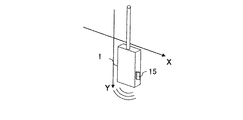
超音波探触子1は、検査対象の部位、形状、検査の目的等により種々の形態のものがあり、その種類は限定されないが、一般に複数の振動素子を直線状や円弧状に配列させた構造を有し、列の一端から他端まで一定間隔の時間差で駆動するように構成されている。超音波探触子1には、図2に示すように、超音波ビームの走査方向(図中、矢印で示す方向)で決まる面(走査面)の表裏を認識させるためのマーカ15として、突起や溝が設けられている。画像表示部4に表示される断層像には、マーカ15に対応する方向マークが表示され、この方向マークにより、操作者は表示されている断層像が走査面のどちら側から見た断層像なのかを知ることができる。この断層像を見る方向を視線方向という。
The
なお超音波探触子1には、素子配列が複数列のものもあり、本発明の超音波画像装置はこのような複数列のものも採用できる。
Note that some
超音波送受信回路2および超音波信号変換部3の構成は、従来の超音波画像装置と同様であり、超音波信号発信のためのパルス発生回路、エコー信号を増幅するためのビデオ増幅器、Aモード信号をデジタル量として記憶しテレビ映像信号とするDSC(ディジタルスキャンコンバータ)などを備えている。また周波数分析部を備えたドプラ回路などを備えていてもよい。 The configuration of the ultrasonic transmission / reception circuit 2 and the ultrasonic signal converter 3 is the same as that of a conventional ultrasonic imaging apparatus, a pulse generation circuit for transmitting an ultrasonic signal, a video amplifier for amplifying an echo signal, and an A mode. A DSC (Digital Scan Converter) that stores signals as digital quantities and converts them into TV video signals is provided. Further, a Doppler circuit including a frequency analysis unit may be provided.
制御部5は、上述した超音波送受信回路2および超音波信号変換部3の動作を制御する他、入力部6を介して入力された3次元撮影の際の条件、具体的には超音波探触子1の移動方向の設定に従い、断層像を格納する画像メモリ10や3次元画像構築部9の動作も制御する。入力部6は超音波探触子移動方向設定部の機能を有している。制御部5による制御については、超音波画像装置の動作とともに詳述する。
The control unit 5 controls the operations of the ultrasonic transmission / reception circuit 2 and the ultrasonic signal conversion unit 3 described above, and also provides the conditions for three-dimensional imaging input via the input unit 6, specifically the ultrasonic search. The operation of the
入力部6は、操作パネルに備えられたキーやトラックボールのほか、タッチパネル、リモコン、フットスイッチなど種々の入力装置が採用できる。 The input unit 6 can employ various input devices such as a touch panel, a remote controller, and a foot switch in addition to keys and trackballs provided on the operation panel.
グラフィック表示部7は、画像表示部4に表示される断層像とともに、操作者の指標となるオリエンテーション画像、具体的には、超音波探触子の方向マーカに対応するオリエンテーションマークや、検査部位を含む体の部分を模式的に示すボディマークや、超音波探触子(プローブ)を示すプローブマーク等を格納している。これらオリエンテーション画像は、種々の体の部分に対応して、またプローブの種類に対応して、種々のマークが用意され格納されている。表示させるボディマークおよびプローブマークの種類は、操作者が入力部6を介して選択する。
The
表示系制御部8は、画像表示部4に表示させるオリエンテーション画像の表示を制御する。具体的には、選択されたボディマークに対して、被検体に超音波探触子を当てる位置(走査面)に対応する位置にプローブマークを配置する。このプローブマークの配置は入力部6を介して操作者が設定する。なお図では、表示系制御部8は、制御部5と別な要素として記載されているが、制御部5が表示系制御部8の機能を持つことも可能である。
The display
次に上記構成の超音波画像装置の動作を説明する。断層像の撮影は、従来の超音波画像装置の動作と同様であり、ここでは3次元撮影の手順を中心に説明する。図3に、3次元撮影の場合の動作のフローチャートを示す。 Next, the operation of the ultrasonic imaging apparatus having the above configuration will be described. The tomographic imaging is the same as the operation of the conventional ultrasonic imaging apparatus, and here, the description will focus on the procedure of 3D imaging. FIG. 3 shows a flowchart of the operation in the case of three-dimensional imaging.
3次元撮影は、超音波探触子1を検査対象の所望の位置、例えば観察しようとする部位の表面に当てて、ビーム走査面とほぼ直交する方向に超音波探触子1を移動させながら、連続して撮影を行い、複数枚の断層像を取得する。このため、まず制御部5は、超音波探触子1を移動の開始位置に当てた状態で断層像を取得し、画像表示部4に表示する(ステップ301)。操作者は、画像表示部4の画面に表示された断層像の視線方向が所望の方向であるかどうかを確認した後、断層像上に関心領域(ROI)を設定し、超音波探触子1を表示された断層像を基準として、基準より手前側を観察するのか、基準より奥側を観察するのか、すなわち超音波探触子1の超音波探触子移動方向を決める。
In 3D imaging, the
視線方向とは、二次元断面である走査面を表裏いずれの方から見るかという方向であり、操作者が任意に切り替えることができるように構成されている。例えば図4(a)に示すように、超音波探触子1の方向マーカ15を操作者から見て右側となるように超音波探触子1を持って撮影したときにビーム走査面を操作者側から見た断層像401は、視線方向402を切り替えた場合、ビーム走査面を反対側から見た断層像と切り替えられる。この場合、視線方向は、操作者の主観的な視線方向とは逆である。一方、図4(b)に示すように、操作者は、超音波探触子1の方向マーカ15を操作者から見て左側となるようにして持ち替えて撮影したときにも、視線方向を切り替えることにより、ビーム走査面を操作者側から見た断層像403を表示させることができる。ここで、断層像401が表示される場合には(図4(a))、断層像401の右側に方向マーカ15に対応するマーク405が表示され、断層像403が表示される場合には(図4(b))、断層像403の左側に方向マーカ15に対応するマーク405が表示される。操作者は、超音波探触子1の方向マーカ15と画面に表示されるマーク405が同じ右側或いは左側であることを確認するだけで、視線方向を確認することができる。
The line-of-sight direction is a direction in which the scanning surface, which is a two-dimensional cross section, is viewed from the front or back, and is configured so that the operator can arbitrarily switch. For example, as shown in FIG. 4 (a), the beam scanning plane is operated when the
このように、操作者は視線方向を確認した後、超音波探触子1の超音波探触子移動方向を入力部6に入力する。
具体的には、操作者は超音波探触子移動方向として、画面に表示された断層像の面(xy面)の位置をz=0とし、手前から奥側への移動(視線方向と同じ方向)か、手前側への移動(視線方向と逆方向)かを入力部6に設定する(ステップ302)。ここでは視線方向と同じ方向を+z方向、視線方向と逆方向を−z方向と定義する。Thus, after confirming the line-of-sight direction, the operator inputs the ultrasonic probe moving direction of the
Specifically, the operator sets the position of the plane (xy plane) of the tomographic image displayed on the screen to z = 0 as the ultrasonic probe movement direction, and moves from the near side to the back side (the same as the line-of-sight direction). Direction) or forward movement (direction opposite to the line of sight) is set in the input unit 6 (step 302). Here, the same direction as the line-of-sight direction is defined as + z direction, and the direction opposite to the line-of-sight direction is defined as -z direction.
次いで操作者は超音波探触子1を移動させながら、制御部5は撮影を行う(ステップ303)。超音波探触子1は所定の速度でビーム走査を行い、1回のビーム走査で得られたエコー信号を用いて超音波信号変換部3がビーム走査面の断層像データを作成する。撮影範囲の設定には種々の方法があるが、通常、入力部6を介して、移動距離、収集時間、収集ピッチなどを設定することにより移動範囲を設定する。断層像は収集時間×フレームレート(1秒あたりの断層像の取得枚数)の数を収集する。超音波探触子を移動させながら収集した複数枚の断層像データは、順次画像メモリ10内に収納される(ステップ304)。
Next, the controller 5 performs imaging while moving the ultrasonic probe 1 (step 303). The
操作者は超音波探触子1を停止させて制御部5は撮影を終了すると、3次元画像構築部9は、画像メモリ10から格納された複数枚の断層像を取り込み、3次元画像を構築する(ステップ305、306)。ここで、ステップ302において、超音波探触子の移動方向が[+z方向]に設定されている場合には、画像メモリ10から読み出す断層像の順序は画像メモリ10内に格納されている断層像の格納順序と同じにする(ステップ305)。一方、超音波探触子の移動方向が[−z方向]に設定されている場合には、画像メモリ10から読み出す断層像の順序を画像メモリ10内に格納されている断層像の格納順序とは逆にする(ステップ306)。
When the operator stops the
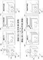
この様子を図5に示す。図5の上段は超音波探触子の移動方向501が[+z方向]に設定されている場合すなわち視線方向502と同じ場合を示し、下段は超音波探触子の移動方向501’が[−z方向]に設定されている場合すなわち視線方向502と逆方向の場合を示す。
This is shown in FIG. The upper part of FIG. 5 shows the case where the moving
それぞれの左端に、検査対象500に対する超音波探触子1の移動方向501と視線方向502との関係が示されている。
At each left end, a relationship between the moving
図5に示すように、複数枚の断層像が画像メモリ503、503’に収納される順番が、断層像の取得順序であることは、超音波探触子の移動方向が[+z方向]の場合も[−z方向]の場合も同じである。一方、3次元画像構築部9が画像メモリ503、503’から読み出す順序は、[+z方向]の場合と[−z方向]の場合では逆である。つまり断層像の取得順序に拘わらず、3次元画像構築部9で構築される3次元画像空間504、504’では、常に視線方向の手前から奥側に断面が並ぶことになる。
As shown in FIG. 5, the order in which a plurality of tomographic images are stored in the
こうして構築された3次元画像は、画像表示部4に表示される(ステップ307)。表示の向きは、3次元画像構築部9で構築された3次元画像505、505’がそのまま表示されるので、超音波探触子1をどちら方向に移動した場合にも、操作者から見て手前側にある画像が3次元画像の最前面に表示される。
The three-dimensional image constructed in this way is displayed on the image display unit 4 (step 307). As the display direction, the
操作者は必要に応じて、上述したステップ301〜307を繰り返す。その際、操作者が超音波探触子1を持ち替えた場合でも、操作者は、画面に表示された画像を基準として超音波探触子1の移動方向を設定すればよく、それによって常に視線方向からの画像が表示された3次元画像を表示させることができる。
The operator repeats
以上、説明したように、本実施の形態は、超音波探触子と、検査対象に前記超音波探触子を介して超音波信号を送受信させる送受信回路と、受信した超音波信号を用いて検査対象の超音波断層像を構成する画像構成部と、前記超音波画像を表示する表示部と、前記画像構成部および前記表示部を制御する制御部とを備えた超音波画像装置であって、前記超音波探触子を前記超音波断層像と交差する方向に移動したときに取得される複数枚の超音波断層像を用いて3次元画像を構築する3次元画像構築部と、前記表示部の画面に表示された超音波断層像を基準として、それと交差する第1の方向と、当該第1の方向と反対向きの第2の方向のいずれかの超音波探触子移動方向を設定する超音波探触子移動方向設定部と、を備え、前記制御部は、前記超音波探触子移動方向設定部によって設定された超音波探触子移動方向に応じて、前記3次元画像構築部において構築される3次元画像における複数枚の超音波断層像の配置順序を制御するので、表示画像の操作者の方向誤認等を防止することが可能な超音波画像装置を提供することができる。 As described above, the present embodiment uses an ultrasonic probe, a transmission / reception circuit that transmits / receives an ultrasonic signal to the inspection target via the ultrasonic probe, and a received ultrasonic signal. An ultrasound imaging apparatus comprising: an image configuration unit that configures an ultrasonic tomographic image to be examined; a display unit that displays the ultrasound image; and a control unit that controls the image configuration unit and the display unit. A three-dimensional image constructing unit that constructs a three-dimensional image using a plurality of ultrasonic tomographic images acquired when the ultrasonic probe is moved in a direction intersecting the ultrasonic tomographic image, and the display Using the ultrasonic tomogram displayed on the screen of the unit as a reference, set the ultrasonic probe movement direction in either the first direction that intersects it or the second direction opposite to the first direction. An ultrasonic probe movement direction setting unit, and the control unit The arrangement order of a plurality of ultrasonic tomographic images in the three-dimensional image constructed in the three-dimensional image construction unit is controlled according to the ultrasonic probe movement direction set by the wave probe movement direction setting unit Therefore, it is possible to provide an ultrasonic imaging apparatus capable of preventing misdirection of the operator of the display image.
また、前記制御部は、前記3次元画像構築部で構築された3次元画像を前記表示部に表示させるとともに、前記設定された超音波探触子移動方向に応じて、表示される3次元画像の方向を制御しても、表示画像の操作者の方向誤認等を防止することが可能な超音波画像装置を提供することができる。 The control unit causes the display unit to display the three-dimensional image constructed by the three-dimensional image construction unit, and displays the three-dimensional image displayed according to the set ultrasonic probe moving direction. It is possible to provide an ultrasonic imaging apparatus that can prevent misperception of the operator of the displayed image even if the direction of the image is controlled.
また、前記超音波探触子移動方向設定部として、前記超音波探触子の移動方向を入力するための入力部を備えても、表示画像の操作者の方向誤認等を防止することが可能な超音波画像装置を提供することができる。 Further, even if an input unit for inputting the moving direction of the ultrasonic probe is provided as the moving direction setting unit of the ultrasonic probe, it is possible to prevent misdirection of the operator of the display image. An ultrasonic imaging apparatus can be provided.
また、前記制御部は、前記超音波探触子移動方向が、前記表示部の画面に対する視線方向と同方向であるときに、前記超音波探触子の移動に伴い取得される複数の超音波断層像を時系列順に前記3次元画像空間に格納して3次元画像を構築し、前記移動方向が、前記表示部の画面に対する視線方向と逆方向であるときに、前記超音波探触子の移動に伴い取得される複数の超音波断層像を時系列とは逆の順序で前記3次元画像空間に格納して3次元画像を構築しても、表示画像の操作者の方向誤認等を防止することが可能な超音波画像装置を提供することができる。 The control unit may include a plurality of ultrasonic waves acquired along with the movement of the ultrasonic probe when the moving direction of the ultrasonic probe is the same as the line-of-sight direction with respect to the screen of the display unit. Tomographic images are stored in the three-dimensional image space in time series order to construct a three-dimensional image, and when the moving direction is opposite to the line-of-sight direction with respect to the screen of the display unit, Even if a plurality of ultrasonic tomographic images acquired with movement are stored in the 3D image space in the reverse order of the time series, a 3D image can be constructed to prevent misrecognition of the operator of the displayed image. It is possible to provide an ultrasonic imaging apparatus capable of doing so.
また、検査対象に超音波探触子を介して超音波信号を送受信させるステップと、受信した超音波信号を用いて検査対象の超音波断層像を構成するステップと、前記超音波画像を表示するステップと、を含む超音波画像を用いた三次元画像表示方法であって、前記超音波探触子を前記超音波断層像と交差する方向に移動したときに取得される複数枚の超音波断層像を用いて3次元画像を構築するステップと、画面に表示された超音波断層像を基準として、それと交差する第1の方向と、当該第1の方向と反対向きの第2の方向のいずれかの超音波探触子移動方向を設定するステップと、前記設定された超音波探触子移動方向に応じて、前記3次元画像構築部において構築される3次元画像における複数枚の超音波断層像の配置順序を制御するステップとを含んでいるので、表示画像の操作者の方向誤認等を防止することが可能な超音波画像を用いた三次元画像表示方法を提供することができる。
A step of transmitting and receiving an ultrasonic signal to the inspection target via an ultrasonic probe; a step of forming an ultrasonic tomographic image of the inspection target using the received ultrasonic signal; and displaying the ultrasonic image A three-dimensional image display method using an ultrasonic image including a plurality of ultrasonic tomographic images acquired when the ultrasonic probe is moved in a direction intersecting the ultrasonic tomographic image A step of constructing a three-dimensional image using the image, a first direction intersecting with the ultrasonic tomogram displayed on the screen as a reference, and a second direction opposite to the first direction. A step of setting the ultrasonic probe movement direction, and a plurality of ultrasonic tomograms in the three-dimensional image constructed in the three-dimensional image construction unit according to the set ultrasonic probe movement direction and controlling the arrangement order of the image Since comprise, it is possible to provide a three-dimensional image display method using the ultrasonic image capable of preventing the direction misidentification of the operation's display image.
本実施の形態によれば、超音波探触子の物理的な走査面に対して超音波探触子の移動方向を定義するのではなく、画面に表示された断層像に対して移動方向を定義し、それに対応して3次元画像を構築するので、超音波探触子がどのような向きになっていても、移動方向の誤設定する可能性が極めて少なく、それによって鏡像が表示されるという問題や誤診断を防止できる。 According to the present embodiment, the moving direction of the ultrasonic probe is not defined with respect to the physical scanning plane of the ultrasonic probe, but the moving direction is set with respect to the tomographic image displayed on the screen. Since the definition and the corresponding 3D image are constructed, there is very little possibility of incorrect setting of the moving direction regardless of the orientation of the ultrasound probe, and a mirror image is displayed accordingly. Problems and misdiagnosis can be prevented.
また、本実施の形態の特有の効果は、操作者が画面のみを見ながら3次元撮影を行うことができ、また、視線方向と画像の表示方向が一致した画像を常に表示させることができることである。 In addition, the unique effect of this embodiment is that the operator can perform 3D imaging while looking only at the screen, and can always display an image in which the line-of-sight direction matches the image display direction. is there.
また、3次元撮影機能を備えた超音波画像装置において、超音波探触子移動方向の設定を表示されている画像すなわち画像に対する視線方向を基準に設定することができ、その際、視線方向に一致する画像を表示することができるので、操作者の勘違いによる移動方向の誤指定やそれによる鏡像画像の表示などを防止することができる。 Further, in an ultrasonic imaging apparatus having a three-dimensional imaging function, the setting of the ultrasonic probe movement direction can be set based on the displayed image, that is, the visual line direction with respect to the image. Since the matching images can be displayed, it is possible to prevent erroneous designation of the moving direction due to misunderstanding of the operator and display of the mirror image due to the misdirection.
また、本実施の形態によれば、移動方向を示すオリエンテーション画像を表示させることにより、操作者の超音波探触子移動動作を誘導することができ、操作者は手元を気にすることなく画像表示部の画面のみを確認して位置関係を把握することができる。 Further, according to the present embodiment, it is possible to guide the operator's ultrasonic probe moving operation by displaying the orientation image indicating the moving direction, and the operator can view the image without worrying about the hand. It is possible to grasp the positional relationship by confirming only the screen of the display unit.
<第2の実施の形態>
本実施の形態の超音波画像装置も、装置の構成は図1に示したものと同様であるが、本実施の形態では、グラフィック表示部7に、ボディマークやプローブマークのほかに、3次元撮影において、入力部6を介して設定された超音波探触子1の移動方向を示す移動方向マークを表示させることが特徴であり、そのためグラフィック表示部7には、二つの移動方向(+z方向と−z方向)に対応する2種類の移動方向マークが格納されている。図6に、方向マークの一例と、それが断層像とともに画面に表示された様子を示す。<Second Embodiment>
The configuration of the ultrasonic imaging apparatus of the present embodiment is the same as that shown in FIG. 1, but in the present embodiment, in addition to the body mark and the probe mark, a three-dimensional display is provided on the
本実施の形態も3次元撮影の手順は第1の実施の形態と同様であるが、図3のステップ302において超音波探触子1の移動方向が設定されると、図6に示すように、断層像601を表示した画面600にその移動方向601、601’を示す方向マーク605或いは605’が表示される。図示する例では、移動方向が視線方向602と同じ[+z方向]の場合(上段)、断層面の奥側に向かう先細りの矢印が描画された方向マーク605が表示され、移動方向が視線方向602と逆の[−z方向]の場合(下段)、断層面の手前側に向かう先太りの矢印が描画された方向マーク605’が表示される。なお移動方向は入力部6から設定変更も可能であり、それに追従して表示される方向マークも更新される。
In this embodiment, the procedure of 3D imaging is the same as that of the first embodiment, but when the moving direction of the
その他の構成は、第1の実施の形態と同様であり、説明を省略する。 Other configurations are the same as those in the first embodiment, and a description thereof will be omitted.
本実施形態によれば、前記表示部に表示させるオリエンテーション画像を記憶する画像記憶部を有し、 前記画像記憶部は、前記オリエンテーション画像として、前記超音波探触子の移動方向を示す移動方向マーク画像を備え、前記制御部は、前記表示部の画面に表示された超音波断層像とともに前記移動方向マーク画像を表示させるので、画面に表示される画像に対しての移動を、奥行き方向の位置関係を表す方向マークによって、操作者に促すことができるので、操作者の移動方法の誘導が可能となり、視線方向に対する認識がより容易且つ直感的になる。 According to the present embodiment, the image storage unit stores an orientation image to be displayed on the display unit, and the image storage unit indicates a movement direction mark indicating a movement direction of the ultrasonic probe as the orientation image. An image, and the control unit displays the moving direction mark image together with the ultrasonic tomographic image displayed on the screen of the display unit. Since the operator can be urged by the direction mark indicating the relationship, the operator can be guided in the movement method, and recognition of the line-of-sight direction becomes easier and intuitive.
また、診断用の超音波画像装置、特にリアルタイム診断を行う装置では、検査、診断を効率的に行うために操作者の視線を画面から外れさせない状態で、2次元画像(断層像)上での関心領域の抽出、3次元画像構築、3次元画像診断まで一連の動作を行うことが好ましいが、本実施の形態によれば、移動方向を示すオリエンテーション画像を表示させることにより、このような要請を実現できる。 In addition, in an ultrasonic imaging apparatus for diagnosis, particularly an apparatus that performs real-time diagnosis, in order to perform inspection and diagnosis efficiently, the operator's line of sight is not deviated from the screen and is displayed on a 2D image (tomographic image). Although it is preferable to perform a series of operations from region of interest extraction, 3D image construction, and 3D image diagnosis, according to the present embodiment, such a request can be made by displaying an orientation image indicating the moving direction. realizable.
<第3の実施の形態>
本実施の形態の超音波画像装置の全体概要を、図7に示す。図7において、図1の超音波画像装置と同じ符号で示す要素は、図1の超音波画像装置と同様の機能を有する。
本実施の形態の超音波画像装置は、図7に示すように、超音波探触子1の実空間における位置を検出する位置情報センサ12を備える点および制御部5が位置情報センサ12からの位置情報を用いて検査対象の表面とほぼ平行な面すなわち超音波探触子1のビーム走査面と直交する面における超音波探触子1の位置と移動方向とを表示部に表示させる機能を有する点が異なる。グラフィック表示部7には、ボディマークやプローブマークのほかに、その移動方向を示す移動方向マークが収納されている。<Third embodiment>
An overall outline of the ultrasonic imaging apparatus according to the present embodiment is shown in FIG. In FIG. 7, elements denoted by the same reference numerals as those of the ultrasonic imaging apparatus of FIG. 1 have the same functions as those of the ultrasonic imaging apparatus of FIG.
As shown in FIG. 7, the ultrasonic imaging apparatus according to the present embodiment includes a position information sensor 12 that detects the position of the
以下、図1の超音波画像装置と異なる要素を中心に、本実施の形態を説明する。 Hereinafter, the present embodiment will be described focusing on elements different from the ultrasonic imaging apparatus of FIG.
位置情報センサ12は、公知の磁気式、光学式或いは機械式などの3次元位置検出器を採用することができる。 The position information sensor 12 can employ a known three-dimensional position detector such as a magnetic type, an optical type, or a mechanical type.
制御部5は、位置情報センサ12から送られてくる実空間における位置情報を、グラフィック表示部7に収納されたオリエンテーション画像の画像空間の位置情報に変換する座標変換部51を備えている。座標変換部51の位置情報は、表示系制御部8に与えられる。表示系制御部8は、座標変換部51からの位置情報を用いて、プローブマークの位置の調整と移動方向マークの位置や角度の調整を行う。
Control unit 5, the position information in the real space transmitted from the position information sensor 12, and a coordinate
本実施の形態の超音波画像装置にて3次元撮影する場合の動作を説明する。撮影の開始にあたり、3次元撮影の開始位置である断面の断層像を撮像し、表示させることは第一の実施形態と同様である。この際、画像表示部4の画面には、図8に示すように、ボディマークを含むオリエーテンション画像805を表示させる。ボディマークは、グラフィック表示部7に格納されているオリエンテーション画像から検査部位に合ったものを操作者が選択し、表示させる。図示する例では、人の腹部を示すボディマークが表示されている。
An operation in the case of performing three-dimensional imaging with the ultrasonic imaging apparatus of the present embodiment will be described. At the start of imaging, a cross-sectional tomographic image that is the start position of 3D imaging is captured and displayed, as in the first embodiment. At this time, an
一方、位置情報センサ12は、検査部位に置かれた超音波探触子1の実空間における位置を検出し、制御部に送る。位置情報は、例えば、実空間の所定位置を原点とし、回転および平行移動情報を含む行列パラメータを掛け合わせることにより、移動後の超音波探触子1の3次元座標を計算することができる。座標変換部51は、このような超音波探触子座標と実空間座標との座標変換および実空間座標とボディマークの画像空間の座標との座標変換を行い、超音波探触子1の位置と向きの情報を算出して表示系制御部8に渡す。表示系制御部8は、座標変換部51からの位置情報に従い、ボディマーク上に超音波探触子の位置を示すマーク(プローブマーク)806を描出させる。なお被検体とボディマークとの位置関係は、被検体(患者)を寝台の所定の位置に寝かせることにより、関連性をつけておくことができる。被検体についても、身体的な特徴のある部位の位置を位置情報センサ12で計測し、ボディマークの該当位置と関連付けておくことも可能である。
On the other hand, the position information sensor 12 detects the position of the
次いで、入力部6から超音波探触子1の超音波探触子移動方向が設定されると、その移動方向801を示す移動方向マーク807をボディマーク上に表示する。図8の上段は、超音波探触子1を視線方向802と同じ方向に移動する場合を示し、下段は、超音波探触子1を視線方向802の逆方向に移動する場合を示している。画面には、この方向の違いを矢印で表わされた移動方向マーク807が表示される。これにより操作者は、画面を見て超音波探触子1を移動させる方向を確認しながら、3次元撮影を行うことができる。ボディマーク上に表示された移動マークは、移動方向を上から参照したマークであるため、奥行き方向を示す表示マークに比べ、認識がより容易になる。
Next, when the ultrasonic probe moving direction of the
3次元撮影が開始された後の手順は、第1の実施形態において図3のフローで説明したステップ303〜307と同様である。すなわち、断層像を撮像順に画像メモリ10に格納するとともに、超音波探触子1の移動方向が+z方向か−z方向かに応じて、画像メモリ10から読み出す順序を異ならせて3次元画像の構築を行い、視線方向手前の画像が手前になるように3次元画像を表示させる。
The procedure after the start of 3D imaging is the same as
本実施形態によれば、超音波探触子の実空間における位置情報を検出する位置センサを備え、前記制御部は、前記位置センサからの位置情報をもとに、検査対象を表すオリエンテーション画像上に、前記超音波探触子の位置及び向き並びに前記設定された超音波探触子移動方向を表示させるので、被検体に対する超音波探触子の移動方向を表示することができるため、第1および第2の実施形態と同様の効果に加えて、より向上した操作性を提供できる。 According to the present embodiment, it is provided with a position sensor that detects position information of the ultrasonic probe in real space, and the control unit is arranged on an orientation image representing an inspection object based on the position information from the position sensor. In addition, since the position and orientation of the ultrasonic probe and the set ultrasonic probe moving direction are displayed, the moving direction of the ultrasonic probe relative to the subject can be displayed. In addition to the same effects as those of the second embodiment, improved operability can be provided.
また、前記制御部は、前記位置センサからの位置情報をもとに、前記超音波探触子が移動した範囲及び/又は方向を示す移動マークを前記オリエンテーション画像上に表示させても、第1および第2の実施形態と同様の効果に加えて、より向上した操作性を提供できる。 In addition, even if the control unit displays a movement mark indicating the range and / or direction of movement of the ultrasonic probe on the orientation image based on the position information from the position sensor, In addition to the same effects as those of the second embodiment, improved operability can be provided.
また、本実施形態の超音波画像装置は、超音波探触子1の位置情報を利用して、超音波探触子1が実際に移動した軌跡を表示させたり、移動範囲を表示させたりすることも可能である。
In addition, the ultrasonic imaging apparatus according to the present embodiment uses the positional information of the
表示の一例を図9に示す。図示する例では、最初に超音波探触子の移動方向を設定したときにプローブマーク906とともに表示される移動方向マーク907とは別に、実際に超音波探触子が移動した方向を示す移動マーク908がボディマーク905上に表示される。これによって、操作者は意図した方向と異なる方向に超音波探触子を移動したかどうかを確認でき、再撮影するかどうかを判断することができる。最初の設定からのずれが大きい場合には、移動マークの色を変えたり、点滅表示にするなど強調することにより、操作者に注意を促すことも可能である。また設定した移動方向と実際の移動方向とが逆の場合には、表示が逆方向になるので、その旨を上述のような警告とともに或いはそれに代えて文字列909等で表示することも可能である。その他、表示の手法については種々の手法を採用することができる。また超音波探触子の移動範囲についても、矢印の長さで表現してもよいし、移動終了の時点で範囲を示すマークを表示させることも可能である。
An example of the display is shown in FIG. In the illustrated example, apart from the
また、一般にボディマークやプローブマーク等のオリエンテーション画像は、撮影の際の指標となるのみでなく、表示された断層像とともに記録することにより、断層像だけではわかりにくい断面位置などを参照するのに役立つ。上述のように、実際に移動した超音波探触子1の情報をオリエンテーション画像として表示することにより、移動領域の範囲や方向等の3次元撮影条件を容易に認識することが可能となる。
In general, orientation images such as body marks and probe marks not only serve as indices for shooting, but are recorded together with the displayed tomographic images to refer to cross-sectional positions that are difficult to understand with only tomographic images. Useful. As described above, by displaying the information of the actually moved
本発明によれば、超音波画像装置による3次元撮影において、操作者の操作性を向上することができ、画面を見ながら診断から画像表示までの一連の動作を行うことができる。また逆方向表示など誤診断につながる表示を防止できる。 According to the present invention, the operator's operability can be improved in three-dimensional imaging using an ultrasonic imaging apparatus, and a series of operations from diagnosis to image display can be performed while viewing the screen. In addition, it is possible to prevent a display such as a reverse display that leads to a wrong diagnosis.
1 超音波探触子、2 超音波送受信回路、3 超音波信号変換部、4 画像表示部、5 制御部、6 入力部、7 グラフィック表示部、8 表示系制御部、9 3次元画像構築部、10 画像メモリ、11 合成部、12 位置情報センサ、15 方向マーカ 1 Ultrasonic probe, 2 Ultrasonic transmitter / receiver circuit, 3 Ultrasonic signal converter, 4 Image display unit, 5 Control unit, 6 Input unit, 7 Graphic display unit, 8 Display system control unit, 9 3D image construction unit , 10 image memory, 11 composition unit, 12 position information sensor, 15 direction marker
Claims (14)
前記超音波探触子を前記超音波断層像と交差する方向に移動したときに取得される複数枚の超音波断層像を用いて3次元画像を構築する3次元画像構築部と、
前記表示部の画面に表示された超音波断層像を基準として、それと交差する第1の方向と、当該第1の方向と反対向きの第2の方向のいずれかの超音波探触子移動方向を設定する超音波探触子移動方向設定部と、を備え
前記制御部は、前記超音波探触子移動方向設定部によって設定された超音波探触子の移動方向に応じて、前記3次元画像構築部において構築される3次元画像における複数枚の超音波断層像の配置順序を制御することを特徴とする超音波画像装置。 An ultrasonic probe, a transmission / reception circuit that transmits / receives an ultrasonic signal to / from the inspection target via the ultrasonic probe, and an image configuration unit that forms an ultrasonic tomographic image of the inspection target using the received ultrasonic signal An ultrasonic imaging apparatus comprising: a display unit that displays the ultrasonic tomogram; and a control unit that controls the image configuration unit and the display unit,
A three-dimensional image construction unit that constructs a three-dimensional image using a plurality of ultrasonic tomographic images acquired when the ultrasonic probe is moved in a direction intersecting the ultrasonic tomographic image;
Based on the ultrasonic tomographic image displayed on the screen of the display unit, therewith the first direction crossing, any of ultrasonic feeler KoUtsuri movement in the second direction between the first direction opposite An ultrasonic probe moving direction setting unit for setting a direction, and the control unit is configured to perform the operation according to the moving direction of the ultrasonic probe set by the ultrasonic probe moving direction setting unit. An ultrasonic imaging apparatus that controls an arrangement order of a plurality of ultrasonic tomographic images in a three-dimensional image constructed in a three-dimensional image construction unit.
前記画像記憶部は、前記オリエンテーション画像として、前記超音波探触子の移動方向を示す移動方向マーク画像を備え、
前記制御部は、前記表示部の画面に表示された超音波断層像とともに前記移動方向マーク画像を表示させることを特徴とする請求項1に記載の超音波画像装置。 An image storage unit for storing an orientation image to be displayed on the display unit;
The image storage unit includes a moving direction mark image indicating a moving direction of the ultrasonic probe as the orientation image,
2. The ultrasonic imaging apparatus according to claim 1, wherein the control unit displays the moving direction mark image together with the ultrasonic tomographic image displayed on the screen of the display unit.
前記制御部は、前記位置センサからの位置情報をもとに、検査対象を表すオリエンテーション画像上に、前記超音波探触子の位置及び向き並びに前記設定された超音波探触子の移動方向を表示させることを特徴とする請求項5に記載の超音波画像装置。 A position sensor for detecting position information of the ultrasonic probe in real space;
Based on the position information from the position sensor, the control unit determines the position and orientation of the ultrasonic probe and the set moving direction of the ultrasonic probe on an orientation image representing an inspection object. 6. The ultrasonic imaging apparatus according to claim 5, wherein the ultrasonic imaging apparatus is displayed.
前記超音波断層像とともに前記オリエンテーション画像を表示するステップを含むことを特徴とする請求項8に記載の三次元画像表示方法。 Storing a moving direction mark image indicating a moving direction of the ultrasonic probe as an orientation image;
9. The three- dimensional image display method according to claim 8, further comprising a step of displaying the orientation image together with the ultrasonic tomographic image.
前記位置情報をもとに、検査対象を表すオリエンテーション画像上に、前記超音波探触子の位置及び向き並びに前記設定された超音波探触子移動方向を表示させるステップと、を含むことを特徴とする請求項12に記載の三次元画像表示方法。 Detecting positional information of the ultrasonic probe in real space;
Displaying the position and orientation of the ultrasonic probe and the set ultrasonic probe moving direction on an orientation image representing an inspection object based on the position information. 13. The three- dimensional image display method according to claim 12.
Priority Applications (1)
| Application Number | Priority Date | Filing Date | Title |
|---|---|---|---|
| JP2012527662A JP5784607B2 (en) | 2010-08-06 | 2011-07-21 | Ultrasonic imaging apparatus and three-dimensional image display method |
Applications Claiming Priority (4)
| Application Number | Priority Date | Filing Date | Title |
|---|---|---|---|
| JP2010177048 | 2010-08-06 | ||
| JP2010177048 | 2010-08-06 | ||
| PCT/JP2011/066516 WO2012017827A1 (en) | 2010-08-06 | 2011-07-21 | Ultrasonic imaging apparatus and three-dimensional image display method using ultrasonic image |
| JP2012527662A JP5784607B2 (en) | 2010-08-06 | 2011-07-21 | Ultrasonic imaging apparatus and three-dimensional image display method |
Publications (2)
| Publication Number | Publication Date |
|---|---|
| JPWO2012017827A1 JPWO2012017827A1 (en) | 2013-10-03 |
| JP5784607B2 true JP5784607B2 (en) | 2015-09-24 |
Family
ID=45559333
Family Applications (1)
| Application Number | Title | Priority Date | Filing Date |
|---|---|---|---|
| JP2012527662A Active JP5784607B2 (en) | 2010-08-06 | 2011-07-21 | Ultrasonic imaging apparatus and three-dimensional image display method |
Country Status (5)
| Country | Link |
|---|---|
| US (1) | US9241685B2 (en) |
| EP (1) | EP2601892A4 (en) |
| JP (1) | JP5784607B2 (en) |
| CN (1) | CN103068315B (en) |
| WO (1) | WO2012017827A1 (en) |
Families Citing this family (12)
| Publication number | Priority date | Publication date | Assignee | Title |
|---|---|---|---|---|
| CN103068315B (en) | 2010-08-06 | 2015-03-25 | 株式会社日立医疗器械 | Ultrasonic imaging apparatus and three-dimensional image display method using ultrasonic image |
| JP5835903B2 (en) * | 2011-02-03 | 2015-12-24 | 株式会社東芝 | Ultrasonic diagnostic equipment |
| WO2013154079A1 (en) * | 2012-04-11 | 2013-10-17 | 株式会社東芝 | Ultrasound diagnostic device |
| JP6205709B2 (en) * | 2012-10-30 | 2017-10-04 | セイコーエプソン株式会社 | Ultrasonic measuring device |
| KR20150059059A (en) * | 2013-11-21 | 2015-05-29 | 삼성메디슨 주식회사 | Apparatus and method for displaying ultrasound image |
| WO2016046588A1 (en) * | 2014-09-24 | 2016-03-31 | B-K Medical Aps | Transducer orientation marker |
| KR20170093632A (en) * | 2016-02-05 | 2017-08-16 | 삼성전자주식회사 | Electronic device and operating method thereof |
| EP3203440A1 (en) * | 2016-02-08 | 2017-08-09 | Nokia Technologies Oy | A method, apparatus and computer program for obtaining images |
| CN107689072A (en) * | 2016-06-12 | 2018-02-13 | 中慧医学成像有限公司 | A kind of 3-D view imaging method and system |
| WO2018205274A1 (en) * | 2017-05-12 | 2018-11-15 | 深圳迈瑞生物医疗电子股份有限公司 | Ultrasonic device, and method and system for transforming display of three-dimensional ultrasonic image thereof |
| EP3485816A1 (en) * | 2017-11-21 | 2019-05-22 | Koninklijke Philips N.V. | Method and apparatus for guiding an ultrasound probe |
| JP7447692B2 (en) | 2020-06-16 | 2024-03-12 | コニカミノルタ株式会社 | Ultrasonic diagnostic device, method of controlling the ultrasonic diagnostic device, and control program for the ultrasonic diagnostic device |
Citations (6)
| Publication number | Priority date | Publication date | Assignee | Title |
|---|---|---|---|---|
| JPH0523330A (en) * | 1991-07-17 | 1993-02-02 | Toshiba Corp | Ultrasonic diagnosing apparatus |
| JP2000325347A (en) * | 1999-05-24 | 2000-11-28 | Toshiba Corp | Ultrasonic diagnostic apparatus and method of restructuring three-dimensional image data |
| JP2001017433A (en) * | 1999-07-06 | 2001-01-23 | Toshiba Corp | Ultrasonograph and ultrasonic image display device |
| JP2003325513A (en) * | 2002-05-16 | 2003-11-18 | Aloka Co Ltd | Ultrasonic diagnostic apparatus |
| JP2004057379A (en) * | 2002-07-26 | 2004-02-26 | Aloka Co Ltd | Ultrasonic diagnostic system |
| WO2005096948A1 (en) * | 2004-04-08 | 2005-10-20 | Matsushita Electric Industrial Co., Ltd. | Ultrasonographic equipment |
Family Cites Families (14)
| Publication number | Priority date | Publication date | Assignee | Title |
|---|---|---|---|---|
| JP3361692B2 (en) | 1996-05-10 | 2003-01-07 | ジーイー横河メディカルシステム株式会社 | Ultrasound diagnostic equipment |
| JP3352613B2 (en) * | 1997-10-17 | 2002-12-03 | 松下電器産業株式会社 | Ultrasound image diagnostic equipment |
| JP4064517B2 (en) | 1998-03-12 | 2008-03-19 | 株式会社日立メディコ | Ultrasonic diagnostic equipment |
| JP3905644B2 (en) * | 1998-06-15 | 2007-04-18 | 東芝医用システムエンジニアリング株式会社 | 3D ultrasound system |
| US6413219B1 (en) * | 1999-03-31 | 2002-07-02 | General Electric Company | Three-dimensional ultrasound data display using multiple cut planes |
| US7375455B2 (en) * | 2003-08-08 | 2008-05-20 | Matsushita Electric Industrial Co., Ltd. | Ultrasonic motor driving device and ultrasonic diagnosis apparatus |
| EP1778957A4 (en) * | 2004-06-01 | 2015-12-23 | Biosensors Int Group Ltd | Radioactive-emission-measurement optimization to specific body structures |
| JP4470187B2 (en) | 2004-12-03 | 2010-06-02 | 株式会社日立メディコ | Ultrasonic device, ultrasonic imaging program, and ultrasonic imaging method |
| WO2006064676A1 (en) * | 2004-12-13 | 2006-06-22 | Hitachi Medical Corporation | Ultrasonic diagnosis apparatus |
| JP4745133B2 (en) * | 2006-05-30 | 2011-08-10 | 株式会社東芝 | Ultrasonic diagnostic apparatus, medical image processing apparatus, and medical image processing program |
| JP5268374B2 (en) * | 2008-01-25 | 2013-08-21 | 株式会社東芝 | Ultrasonic diagnostic apparatus and control method thereof |
| EP2312534A3 (en) * | 2009-10-15 | 2011-07-06 | Hitachi Aloka Medical, Ltd. | Ultrasonic volume data processing device |
| JP2011160412A (en) * | 2010-01-06 | 2011-08-18 | Panasonic Corp | Imaging apparatus |
| CN103068315B (en) | 2010-08-06 | 2015-03-25 | 株式会社日立医疗器械 | Ultrasonic imaging apparatus and three-dimensional image display method using ultrasonic image |
-
2011
- 2011-07-21 CN CN201180038803.0A patent/CN103068315B/en active Active
- 2011-07-21 EP EP11814457.5A patent/EP2601892A4/en not_active Withdrawn
- 2011-07-21 JP JP2012527662A patent/JP5784607B2/en active Active
- 2011-07-21 WO PCT/JP2011/066516 patent/WO2012017827A1/en active Application Filing
- 2011-07-21 US US13/814,371 patent/US9241685B2/en active Active
Patent Citations (6)
| Publication number | Priority date | Publication date | Assignee | Title |
|---|---|---|---|---|
| JPH0523330A (en) * | 1991-07-17 | 1993-02-02 | Toshiba Corp | Ultrasonic diagnosing apparatus |
| JP2000325347A (en) * | 1999-05-24 | 2000-11-28 | Toshiba Corp | Ultrasonic diagnostic apparatus and method of restructuring three-dimensional image data |
| JP2001017433A (en) * | 1999-07-06 | 2001-01-23 | Toshiba Corp | Ultrasonograph and ultrasonic image display device |
| JP2003325513A (en) * | 2002-05-16 | 2003-11-18 | Aloka Co Ltd | Ultrasonic diagnostic apparatus |
| JP2004057379A (en) * | 2002-07-26 | 2004-02-26 | Aloka Co Ltd | Ultrasonic diagnostic system |
| WO2005096948A1 (en) * | 2004-04-08 | 2005-10-20 | Matsushita Electric Industrial Co., Ltd. | Ultrasonographic equipment |
Also Published As
| Publication number | Publication date |
|---|---|
| EP2601892A4 (en) | 2017-10-11 |
| EP2601892A1 (en) | 2013-06-12 |
| CN103068315B (en) | 2015-03-25 |
| US20130142010A1 (en) | 2013-06-06 |
| JPWO2012017827A1 (en) | 2013-10-03 |
| US9241685B2 (en) | 2016-01-26 |
| CN103068315A (en) | 2013-04-24 |
| WO2012017827A1 (en) | 2012-02-09 |
Similar Documents
| Publication | Publication Date | Title |
|---|---|---|
| JP5784607B2 (en) | Ultrasonic imaging apparatus and three-dimensional image display method | |
| JP7167285B2 (en) | Ultrasound system and method for breast tissue imaging | |
| KR101182880B1 (en) | Ultrasound system and method for providing image indicator | |
| EP3013243B1 (en) | Elastography measurement system and method | |
| JP5738507B2 (en) | Ultrasonic probe trajectory expression device and ultrasonic diagnostic device | |
| US8535231B2 (en) | Ultrasonic diagnostic apparatus | |
| CN100556360C (en) | Ultrasonic probe track display device and method and diagnostic ultrasound equipment and method | |
| WO2013161277A1 (en) | Ultrasonic diagnosis device and method for controlling same | |
| EP2036500A1 (en) | Ultrasound diagnostic apparatus | |
| WO2014034948A1 (en) | Ultrasonic diagnostic apparatus and image processing method | |
| KR102442178B1 (en) | Ultrasound diagnosis apparatus and mehtod thereof | |
| US20120289830A1 (en) | Method and ultrasound imaging system for image-guided procedures | |
| WO2021033446A1 (en) | Ultrasonic diagnostic apparatus and control method for ultrasonic diagnostic apparatus | |
| JP2009089736A (en) | Ultrasonograph | |
| CN111629671A (en) | Ultrasonic imaging apparatus and method of controlling ultrasonic imaging apparatus | |
| CN111671461A (en) | Ultrasonic diagnostic apparatus and display method | |
| JP2016523164A (en) | Delineation of rib obstructions in anatomically intelligent echocardiography | |
| JP4865575B2 (en) | Ultrasonic diagnostic equipment | |
| RU2620865C2 (en) | System and method for three-dimensional ultrasound measuring volumetric areas | |
| CN112545551A (en) | Method and system for medical imaging device | |
| JP4634814B2 (en) | Ultrasonic diagnostic equipment | |
| KR100875620B1 (en) | Ultrasound Imaging Systems and Methods | |
| EP3826542B1 (en) | Ultrasound system and method for guided shear wave elastography of anisotropic tissue | |
| JP2005006770A (en) | Ultrasonic diagnostic device | |
| JP2009061076A (en) | Ultrasonic diagnostic apparatus |
Legal Events
| Date | Code | Title | Description |
|---|---|---|---|
| A521 | Request for written amendment filed |
Free format text: JAPANESE INTERMEDIATE CODE: A523 Effective date: 20140630 |
|
| A621 | Written request for application examination |
Free format text: JAPANESE INTERMEDIATE CODE: A621 Effective date: 20140630 |
|
| A977 | Report on retrieval |
Free format text: JAPANESE INTERMEDIATE CODE: A971007 Effective date: 20150109 |
|
| A131 | Notification of reasons for refusal |
Free format text: JAPANESE INTERMEDIATE CODE: A131 Effective date: 20150407 |
|
| A521 | Request for written amendment filed |
Free format text: JAPANESE INTERMEDIATE CODE: A523 Effective date: 20150413 |
|
| TRDD | Decision of grant or rejection written | ||
| A01 | Written decision to grant a patent or to grant a registration (utility model) |
Free format text: JAPANESE INTERMEDIATE CODE: A01 Effective date: 20150707 |
|
| A61 | First payment of annual fees (during grant procedure) |
Free format text: JAPANESE INTERMEDIATE CODE: A61 Effective date: 20150722 |
|
| R150 | Certificate of patent or registration of utility model |
Ref document number: 5784607 Country of ref document: JP Free format text: JAPANESE INTERMEDIATE CODE: R150 |
|
| S111 | Request for change of ownership or part of ownership |
Free format text: JAPANESE INTERMEDIATE CODE: R313111 |
|
| S533 | Written request for registration of change of name |
Free format text: JAPANESE INTERMEDIATE CODE: R313533 |
|
| R350 | Written notification of registration of transfer |
Free format text: JAPANESE INTERMEDIATE CODE: R350 |
|
| S111 | Request for change of ownership or part of ownership |
Free format text: JAPANESE INTERMEDIATE CODE: R313111 |
|
| R350 | Written notification of registration of transfer |
Free format text: JAPANESE INTERMEDIATE CODE: R350 |
|
| R250 | Receipt of annual fees |
Free format text: JAPANESE INTERMEDIATE CODE: R250 |
|
| R250 | Receipt of annual fees |
Free format text: JAPANESE INTERMEDIATE CODE: R250 |