JP5782523B2 - System and method for reducing pulsating pressure - Google Patents
System and method for reducing pulsating pressure Download PDFInfo
- Publication number
- JP5782523B2 JP5782523B2 JP2013540109A JP2013540109A JP5782523B2 JP 5782523 B2 JP5782523 B2 JP 5782523B2 JP 2013540109 A JP2013540109 A JP 2013540109A JP 2013540109 A JP2013540109 A JP 2013540109A JP 5782523 B2 JP5782523 B2 JP 5782523B2
- Authority
- JP
- Japan
- Prior art keywords
- compliant body
- reservoir
- pressure
- lumen
- conduit
- Prior art date
- Legal status (The legal status is an assumption and is not a legal conclusion. Google has not performed a legal analysis and makes no representation as to the accuracy of the status listed.)
- Active
Links
Images


Classifications
-
- A—HUMAN NECESSITIES
- A61—MEDICAL OR VETERINARY SCIENCE; HYGIENE
- A61M—DEVICES FOR INTRODUCING MEDIA INTO, OR ONTO, THE BODY; DEVICES FOR TRANSDUCING BODY MEDIA OR FOR TAKING MEDIA FROM THE BODY; DEVICES FOR PRODUCING OR ENDING SLEEP OR STUPOR
- A61M29/00—Dilators with or without means for introducing media, e.g. remedies
- A61M29/02—Dilators made of swellable material
-
- A—HUMAN NECESSITIES
- A61—MEDICAL OR VETERINARY SCIENCE; HYGIENE
- A61M—DEVICES FOR INTRODUCING MEDIA INTO, OR ONTO, THE BODY; DEVICES FOR TRANSDUCING BODY MEDIA OR FOR TAKING MEDIA FROM THE BODY; DEVICES FOR PRODUCING OR ENDING SLEEP OR STUPOR
- A61M25/00—Catheters; Hollow probes
- A61M25/01—Introducing, guiding, advancing, emplacing or holding catheters
- A61M25/02—Holding devices, e.g. on the body
- A61M25/04—Holding devices, e.g. on the body in the body, e.g. expansible
-
- A—HUMAN NECESSITIES
- A61—MEDICAL OR VETERINARY SCIENCE; HYGIENE
- A61M—DEVICES FOR INTRODUCING MEDIA INTO, OR ONTO, THE BODY; DEVICES FOR TRANSDUCING BODY MEDIA OR FOR TAKING MEDIA FROM THE BODY; DEVICES FOR PRODUCING OR ENDING SLEEP OR STUPOR
- A61M60/00—Blood pumps; Devices for mechanical circulatory actuation; Balloon pumps for circulatory assistance
- A61M60/10—Location thereof with respect to the patient's body
- A61M60/122—Implantable pumps or pumping devices, i.e. the blood being pumped inside the patient's body
- A61M60/126—Implantable pumps or pumping devices, i.e. the blood being pumped inside the patient's body implantable via, into, inside, in line, branching on, or around a blood vessel
- A61M60/135—Implantable pumps or pumping devices, i.e. the blood being pumped inside the patient's body implantable via, into, inside, in line, branching on, or around a blood vessel inside a blood vessel, e.g. using grafting
-
- A—HUMAN NECESSITIES
- A61—MEDICAL OR VETERINARY SCIENCE; HYGIENE
- A61M—DEVICES FOR INTRODUCING MEDIA INTO, OR ONTO, THE BODY; DEVICES FOR TRANSDUCING BODY MEDIA OR FOR TAKING MEDIA FROM THE BODY; DEVICES FOR PRODUCING OR ENDING SLEEP OR STUPOR
- A61M60/00—Blood pumps; Devices for mechanical circulatory actuation; Balloon pumps for circulatory assistance
- A61M60/20—Type thereof
- A61M60/295—Balloon pumps for circulatory assistance
-
- A—HUMAN NECESSITIES
- A61—MEDICAL OR VETERINARY SCIENCE; HYGIENE
- A61M—DEVICES FOR INTRODUCING MEDIA INTO, OR ONTO, THE BODY; DEVICES FOR TRANSDUCING BODY MEDIA OR FOR TAKING MEDIA FROM THE BODY; DEVICES FOR PRODUCING OR ENDING SLEEP OR STUPOR
- A61M60/00—Blood pumps; Devices for mechanical circulatory actuation; Balloon pumps for circulatory assistance
- A61M60/40—Details relating to driving
- A61M60/403—Details relating to driving for non-positive displacement blood pumps
- A61M60/405—Details relating to driving for non-positive displacement blood pumps the force acting on the blood contacting member being hydraulic or pneumatic
-
- A—HUMAN NECESSITIES
- A61—MEDICAL OR VETERINARY SCIENCE; HYGIENE
- A61M—DEVICES FOR INTRODUCING MEDIA INTO, OR ONTO, THE BODY; DEVICES FOR TRANSDUCING BODY MEDIA OR FOR TAKING MEDIA FROM THE BODY; DEVICES FOR PRODUCING OR ENDING SLEEP OR STUPOR
- A61M60/00—Blood pumps; Devices for mechanical circulatory actuation; Balloon pumps for circulatory assistance
- A61M60/40—Details relating to driving
- A61M60/497—Details relating to driving for balloon pumps for circulatory assistance
-
- A—HUMAN NECESSITIES
- A61—MEDICAL OR VETERINARY SCIENCE; HYGIENE
- A61M—DEVICES FOR INTRODUCING MEDIA INTO, OR ONTO, THE BODY; DEVICES FOR TRANSDUCING BODY MEDIA OR FOR TAKING MEDIA FROM THE BODY; DEVICES FOR PRODUCING OR ENDING SLEEP OR STUPOR
- A61M60/00—Blood pumps; Devices for mechanical circulatory actuation; Balloon pumps for circulatory assistance
- A61M60/50—Details relating to control
- A61M60/508—Electronic control means, e.g. for feedback regulation
- A61M60/515—Regulation using real-time patient data
- A61M60/531—Regulation using real-time patient data using blood pressure data, e.g. from blood pressure sensors
-
- A—HUMAN NECESSITIES
- A61—MEDICAL OR VETERINARY SCIENCE; HYGIENE
- A61M—DEVICES FOR INTRODUCING MEDIA INTO, OR ONTO, THE BODY; DEVICES FOR TRANSDUCING BODY MEDIA OR FOR TAKING MEDIA FROM THE BODY; DEVICES FOR PRODUCING OR ENDING SLEEP OR STUPOR
- A61M60/00—Blood pumps; Devices for mechanical circulatory actuation; Balloon pumps for circulatory assistance
- A61M60/80—Constructional details other than related to driving
- A61M60/855—Constructional details other than related to driving of implantable pumps or pumping devices
- A61M60/869—Compliance chambers containing a gas or liquid other than blood to compensate volume variations of a blood chamber
-
- A—HUMAN NECESSITIES
- A61—MEDICAL OR VETERINARY SCIENCE; HYGIENE
- A61M—DEVICES FOR INTRODUCING MEDIA INTO, OR ONTO, THE BODY; DEVICES FOR TRANSDUCING BODY MEDIA OR FOR TAKING MEDIA FROM THE BODY; DEVICES FOR PRODUCING OR ENDING SLEEP OR STUPOR
- A61M2205/00—General characteristics of the apparatus
- A61M2205/33—Controlling, regulating or measuring
- A61M2205/3303—Using a biosensor
-
- A—HUMAN NECESSITIES
- A61—MEDICAL OR VETERINARY SCIENCE; HYGIENE
- A61M—DEVICES FOR INTRODUCING MEDIA INTO, OR ONTO, THE BODY; DEVICES FOR TRANSDUCING BODY MEDIA OR FOR TAKING MEDIA FROM THE BODY; DEVICES FOR PRODUCING OR ENDING SLEEP OR STUPOR
- A61M25/00—Catheters; Hollow probes
- A61M25/10—Balloon catheters
- A61M25/1018—Balloon inflating or inflation-control devices
- A61M25/10184—Means for controlling or monitoring inflation or deflation
-
- A—HUMAN NECESSITIES
- A61—MEDICAL OR VETERINARY SCIENCE; HYGIENE
- A61M—DEVICES FOR INTRODUCING MEDIA INTO, OR ONTO, THE BODY; DEVICES FOR TRANSDUCING BODY MEDIA OR FOR TAKING MEDIA FROM THE BODY; DEVICES FOR PRODUCING OR ENDING SLEEP OR STUPOR
- A61M60/00—Blood pumps; Devices for mechanical circulatory actuation; Balloon pumps for circulatory assistance
- A61M60/10—Location thereof with respect to the patient's body
- A61M60/122—Implantable pumps or pumping devices, i.e. the blood being pumped inside the patient's body
- A61M60/165—Implantable pumps or pumping devices, i.e. the blood being pumped inside the patient's body implantable in, on, or around the heart
- A61M60/17—Implantable pumps or pumping devices, i.e. the blood being pumped inside the patient's body implantable in, on, or around the heart inside a ventricle, e.g. intraventricular balloon pumps
-
- A—HUMAN NECESSITIES
- A61—MEDICAL OR VETERINARY SCIENCE; HYGIENE
- A61M—DEVICES FOR INTRODUCING MEDIA INTO, OR ONTO, THE BODY; DEVICES FOR TRANSDUCING BODY MEDIA OR FOR TAKING MEDIA FROM THE BODY; DEVICES FOR PRODUCING OR ENDING SLEEP OR STUPOR
- A61M60/00—Blood pumps; Devices for mechanical circulatory actuation; Balloon pumps for circulatory assistance
- A61M60/20—Type thereof
- A61M60/247—Positive displacement blood pumps
- A61M60/253—Positive displacement blood pumps including a displacement member directly acting on the blood
- A61M60/268—Positive displacement blood pumps including a displacement member directly acting on the blood the displacement member being flexible, e.g. membranes, diaphragms or bladders
- A61M60/274—Positive displacement blood pumps including a displacement member directly acting on the blood the displacement member being flexible, e.g. membranes, diaphragms or bladders the inlet and outlet being the same, e.g. para-aortic counter-pulsation blood pumps
-
- A—HUMAN NECESSITIES
- A61—MEDICAL OR VETERINARY SCIENCE; HYGIENE
- A61M—DEVICES FOR INTRODUCING MEDIA INTO, OR ONTO, THE BODY; DEVICES FOR TRANSDUCING BODY MEDIA OR FOR TAKING MEDIA FROM THE BODY; DEVICES FOR PRODUCING OR ENDING SLEEP OR STUPOR
- A61M60/00—Blood pumps; Devices for mechanical circulatory actuation; Balloon pumps for circulatory assistance
- A61M60/40—Details relating to driving
-
- A—HUMAN NECESSITIES
- A61—MEDICAL OR VETERINARY SCIENCE; HYGIENE
- A61M—DEVICES FOR INTRODUCING MEDIA INTO, OR ONTO, THE BODY; DEVICES FOR TRANSDUCING BODY MEDIA OR FOR TAKING MEDIA FROM THE BODY; DEVICES FOR PRODUCING OR ENDING SLEEP OR STUPOR
- A61M60/00—Blood pumps; Devices for mechanical circulatory actuation; Balloon pumps for circulatory assistance
- A61M60/50—Details relating to control
- A61M60/508—Electronic control means, e.g. for feedback regulation
- A61M60/562—Electronic control means, e.g. for feedback regulation for making blood flow pulsatile in blood pumps that do not intrinsically create pulsatile flow
-
- A—HUMAN NECESSITIES
- A61—MEDICAL OR VETERINARY SCIENCE; HYGIENE
- A61M—DEVICES FOR INTRODUCING MEDIA INTO, OR ONTO, THE BODY; DEVICES FOR TRANSDUCING BODY MEDIA OR FOR TAKING MEDIA FROM THE BODY; DEVICES FOR PRODUCING OR ENDING SLEEP OR STUPOR
- A61M60/00—Blood pumps; Devices for mechanical circulatory actuation; Balloon pumps for circulatory assistance
- A61M60/80—Constructional details other than related to driving
- A61M60/855—Constructional details other than related to driving of implantable pumps or pumping devices
- A61M60/857—Implantable blood tubes
Description
本発明は、概して、脈動圧力を減少させるためのシステムおよび方法に関し、より具体的には、血管内の脈動負荷を減少させるための血管内に埋込み式のコンプライアント本体を有するデバイス、およびデバイスを送達する方法に関する。 The present invention relates generally to systems and methods for reducing pulsating pressure, and more specifically to devices having compliant bodies implantable in blood vessels and devices for reducing pulsating loads in blood vessels. It relates to a method of delivery.
肺動脈高血圧を伴う患者の場合、公知または非公知の疾患過程は、血管収縮および肺小動脈の壁を構成する細胞の増殖をもたらす。これは、血流に対する抵抗を増加させ、かつ肺動脈における定常状態圧力を増加させる結果となる。時間とともに、肺動脈における圧力の増加ならびに他の疾患過程は、肺動脈にその弾性を喪失させ、血管コンプライアンスの減少につながる。血管コンプライアンスは、血管の弾性特性の尺度であり、圧力(ΔV/ΔΡ)における変化に応答して、血管の容積の変化として定義される。コンプライアントである(compliant)血管は、圧力における所与の変化のために、比較的大容積の変化に対応することができる。心臓の鼓動毎に、血液の容積(1回拍出量)は、右心室から肺動脈内に送り込まれる。コンプライアンスが低いとき、肺動脈高血圧が起こるのに伴って、血管は入ってくる血液に対応するために伸長することができないので、右心室は各肺動脈内に1回拍出量を送り込むために、高圧力を生産しなければならない。これは、収縮期と拡張期圧力との間の計算の違いである、高パルス圧力をもたらす。 In patients with pulmonary arterial hypertension, known or unknown disease processes result in vasoconstriction and proliferation of the cells that make up the walls of pulmonary arterioles. This results in increased resistance to blood flow and increased steady state pressure in the pulmonary artery. Over time, increased pressure in the pulmonary artery as well as other disease processes cause the pulmonary artery to lose its elasticity, leading to decreased vascular compliance. Vascular compliance is a measure of the elastic properties of a blood vessel and is defined as a change in the volume of the blood vessel in response to a change in pressure (ΔV / ΔΡ). Compliant vessels can accommodate a relatively large volume change for a given change in pressure. For each heart beat, blood volume (stroke volume) is pumped from the right ventricle into the pulmonary artery. When compliance is low, as the pulmonary arterial hypertension occurs, the blood vessels cannot stretch to accommodate incoming blood, so the right ventricle is high to deliver stroke volume into each pulmonary artery. Must produce pressure. This results in a high pulse pressure, which is the difference in calculation between systolic and diastolic pressure.
動脈壁の異常な高剛性はまた、反射波が有意にパルス圧力に寄与し得るように、パルス伝播速度(PWV)に作用する。PWVは、Moens−Korteweg式: The abnormally high stiffness of the arterial wall also affects the pulse propagation velocity (PWV) so that the reflected wave can contribute significantly to the pulse pressure. PWV is a Moens-Korteweg formula:
![]()
![]()
1983年、Sunagawaは、容積の変化に対する圧力の変化としてエラスタンスの概念を採用した(エラスタンスは、ΔΡ/ΔV、すなわち、コンプライアンスの逆数である)(Sunagawa et al.,Am J Physiol Heart CircPhysiol 245:H773−H780,1983.)。通常の健常者の場合、肺動脈と右心室のエラスタンスとは、整合または結合している。電気回路内のインピーダンス整合と同様に、結合は、最適な一回仕事量およびエネルギー効率の状態を示す(Borlaug et al.,Heart Fail Clin 4:23−36,2008.)。肺動脈のエラスタンスに対する、右心室のエラスタンスの比率の最適値は、1と2との間である(Naeitje et al.,Eur Heart Journal Supplements(2007)9(supplement H),H5−H9.)。肺動脈高血圧の進行期では、この比率は低下させられ、状況は後付加不適合と称された(Borlaug,Ventricular−Vascular Interaction in Heart Failure,Heart Failure Clin 4(2008)23−36.)。この脱結合は、付加的エネルギーが、流れを維持するために必要とされることを示し、したがって、右心室に付加的負荷を負わせる。 In 1983, Sunagawa adopted the concept of elastance as a change in pressure relative to a change in volume (Elastane is ΔΡ / ΔV, ie, the reciprocal of compliance) (Sunagawa et al., Am J Physiol Heart CircPhysiol 245). : H773-H780, 1983.). In normal healthy individuals, the pulmonary artery and right ventricular elastance are aligned or coupled. Similar to impedance matching in electrical circuits, coupling exhibits optimal stroke work and energy efficiency conditions (Borlag et al., Heart Fail Clin 4: 23-36, 2008.). The optimal ratio of right ventricular elastance to pulmonary elastance is between 1 and 2 (Naeitje et al., Eur Heart Journal Supplements (2007) 9 (supplement H), H5-H9.). . In the advanced stage of pulmonary arterial hypertension, this ratio was reduced and the situation was called post-additional incompatibility (Borlag, Venticular-Vascular Interaction in Heart Failure, Heart Failure Clin 4 (2008) 23-36.). This decoupling indicates that additional energy is needed to maintain the flow, thus placing an additional load on the right ventricle.
したがって、当業者によって理解されるであろうように、肺動脈高血圧を伴う患者の肺動脈の比較的低いコンプライアンス(または、高い剛性)は、パルス圧力の増加につながる。それはまた、より高いPWVにつながり、反射波を生じさせ、後負荷をもたらし、さらにパルス圧力を増加させる。さらに、エラスタンス脱結合は、エネルギー非効率の状態および心臓に対する作業負荷の増加につながる。これらの成分は、組み合わさり、脈動負荷につながり、右心室における作業負荷の増加をもたらす。 Thus, as will be appreciated by those skilled in the art, a relatively low compliance (or high stiffness) of a patient's pulmonary artery with pulmonary arterial hypertension leads to an increase in pulse pressure. It also leads to higher PWV, creating a reflected wave, resulting in afterload and further increasing the pulse pressure. Furthermore, elastance decoupling leads to energy inefficiency and increased workload on the heart. These components combine to lead to pulsatile loads, resulting in increased workload in the right ventricle.
肺動脈高血圧では、右心室が血液を送り込むために克服しなければならない総負荷は、定常状態負荷と(小血管収縮によって生じる流れの制限のため)と、脈動負荷(低下コンプライアンスまたは増加剛性によって生じる)との合計と考えられ得る。過去、ほとんどの研究者および医師が、定常状態負荷の対処に注目したが、多くの研究者は、現在、脈動負荷は、心臓に負荷を課すことにおいて、比較的重要であり得ることを感じている。 In pulmonary arterial hypertension, the total load that must be overcome for the right ventricle to pump blood is the steady state load (due to flow limitations caused by small vasoconstriction) and the pulsatile load (caused by reduced compliance or increased stiffness). And can be considered the sum of In the past, most researchers and physicians have focused on dealing with steady-state loads, but many researchers now feel that pulsatile loads can be relatively important in imposing a load on the heart. Yes.
通常の健常者の場合、肺循環は、体循環よりも実質的に低い圧力で動作する。右心室における圧力は、通常、左心室のそれの6分の1である。左心室と比較して、右心室は、慢性的に上昇した圧力および作業負荷に耐える能力が低い。最初、高圧力に曝されると、右心室は、肥大を含む複数の機構を介して、より高い負荷に適合するが、圧力が上昇し続けることに従って、心臓は補償するこの能力を失い、最終的に、右心不全につながり、肺動脈高血圧による死の要因へとつながる。 For normal healthy individuals, pulmonary circulation operates at a pressure substantially lower than systemic circulation. The pressure in the right ventricle is usually one-sixth that of the left ventricle. Compared to the left ventricle, the right ventricle is less capable of withstanding chronically increased pressure and workload. Initially, when exposed to high pressure, the right ventricle adapts to higher loads through multiple mechanisms, including hypertrophy, but as the pressure continues to rise, the heart loses this ability to compensate and eventually In particular, it leads to right heart failure, leading to death due to pulmonary arterial hypertension.
薬物は、肺動脈高血圧のための現在の療法の柱である。肺動脈高血圧特異的薬物の重要な機能は、小肺動脈の拡張である。これらの薬剤は、収縮した血管の断面積を増加することによって、定常状態負荷をより低くする傾向があるが、コンプライアンスの不足によって生じる、上昇される脈動負荷を直接標的にしない。 Drugs are a current therapy pillar for pulmonary arterial hypertension. An important function of pulmonary arterial hypertension-specific drugs is dilatation of small pulmonary arteries. These agents tend to lower the steady state load by increasing the cross-sectional area of the contracted blood vessels, but do not directly target the elevated pulsatile load caused by lack of compliance.
要約すると、多くの肺動脈高血圧患者は、右心室上で慢性的に上昇される負荷に起因する、右心不全が原因で死亡する。増加させられる脈動負荷は、総負荷の重要な成分であって、肺動脈におけるコンプライアンスの相対的な欠如によって生じる。現在の療法は、コンプライアンスの改良に向けられない。したがって、肺動脈のコンプライアンスを増加することによって、脈動負荷を低下させるための解決法の必要性がある。 In summary, many patients with pulmonary arterial hypertension die from right heart failure due to a chronically elevated load on the right ventricle. Increased pulsatile load is an important component of total load and is caused by a relative lack of compliance in the pulmonary artery. Current therapies are not aimed at improving compliance. Therefore, there is a need for a solution to reduce pulsation load by increasing pulmonary artery compliance.
本発明は、リザーバ、注入ポート、経血管導管、およびコンプライアント本体を含む、動脈内の脈動負荷を減少させるためのデバイスを提供することによって、前述の問題に対処する。構成要素の内部空洞は、流動的に相互に連結され、構成要素の間でガスを移動させ、圧力を均一にすることを可能にする。リザーバは、鎖骨下静脈の領域内、またはコンプライアント本体に遠隔の別の好適な場所内の皮膚の下に、載置され得る。リザーバの充填および圧力調節を可能にする注入ポートは、血管外導管によってリザーバに取着される、または直接リザーバ本体に搭載されるかのいずれかであってもよい。経血管導管は、鎖骨下静脈、上大静脈、右心房、および右心室を通過し、リザーバをコンプライアント本体に接続する。コンプライアント本体は、肺動脈内に載置され得、かつ圧縮性または非圧縮性ガスまたは他の好適な流体を囲繞する可撓性薄膜から成る。 The present invention addresses the aforementioned problems by providing a device for reducing the pulsatile load in an artery, including a reservoir, an infusion port, a transvascular conduit, and a compliant body. The internal cavities of the components are fluidly interconnected, allowing gas to move between the components and making the pressure uniform. The reservoir can be placed under the skin in the region of the subclavian vein or in another suitable location remote to the compliant body. The infusion port that allows reservoir filling and pressure regulation may be either attached to the reservoir by an extravascular conduit or directly mounted on the reservoir body. The transvascular conduit passes through the subclavian vein, superior vena cava, right atrium, and right ventricle and connects the reservoir to the compliant body. The compliant body consists of a flexible membrane that can be placed in the pulmonary artery and surrounds a compressible or incompressible gas or other suitable fluid.
デバイスの埋込みは、局所麻酔およびX線透視装置を使用する低侵襲性手術の手段によって行われ得る。例えば、第1の切開が鎖骨下の皮膚に作られ、第2の切開または窓が鎖骨下静脈に作られ得る。ポケットは、リザーバの設置のために寸法設定される第1の切開に隣接する皮下の空間に形成され得る。コンプライアント本体の遠位端は、収縮されたデバイスとともに鎖骨下静脈の中へ挿入され得る。コンプライアント本体および導管は、次いで、コンプライアント本体が肺動脈の中の所望の静止位置に達するまで、前進させられてもよい。必要でなくとも、シースおよび/またはワイヤがデバイスを血管系の中の場所に導くために使用され得る。いったんコンプライアント本体が適切に肺動脈内に据えられると、リバーザは、皮下のポケット内に設置され、および切開は、閉じられ得る。当業者によって理解されるように、圧縮性ガスは、切開が閉じられる前後のいずれかに注入ポートを通してリザーバの中へ注入され得る。
例えば、本発明は、以下の項目を提供する。
(項目1)
脈動圧力を減少させるためのシステムであって、
該システムは、
皮下に埋め込まれるように構築されたリザーバであって、該リザーバは、その中に流体を保持する、リバーザと、
該リザーバと流体連通している注入ポートと、
血管の内腔の中に埋め込まれるように構築されたコンプライアント本体であって、該コンプライアント本体は、少なくとも1つのコンプライアント本体内腔を含み、該コンプライアント本体は、該血管の中の圧力の変化に応じて拡張および圧縮するように構築されている、コンプライアント本体と、
該リザーバと該少なくとも1つのコンプライアント本体内腔との間に延在し、それら
を流動的に連結する経血管導管と
を備え、該コンプライアント本体の該圧縮は、該血管の中のピーク圧力の減少をもたらす、システム。
(項目2)
前記流体は、圧縮性流体である、項目1に記載のシステム。
(項目3)
前記流体は、非圧縮性流体である、項目1に記載のシステム。
(項目4)
血管外導管をさらに備え、該血管外導管は、前記注入ポートと前記リザーバとの間に延在し、それらを流動的に連結する、項目1に記載のシステム。
(項目5)
前記コンプライアント本体は、外側薄膜を含み、該外側薄膜は、弾性材料および非弾性材料から選択される材料から形成される項目1に記載のシステム。
(項目6)
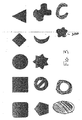
前記コンプライアント本体は、円形形状断面を有する、項目5に記載のシステム。
(項目7)
前記コンプライアント本体は、卵形形状断面を有する、項目5に記載のシステム。
(項目8)
前記コンプライアント本体は、三日月形状断面を有する、項目5に記載のシステム。
(項目9)
前記コンプライアント本体は、丸形の遠位端および近位端を有する細長い円筒として形成される、項目5に記載のシステム。
(項目10)
ポンプをさらに備え、該ポンプは、前記注入ポートに動作可能に連結されて、前記コンプライアント本体の流体量を制御する、項目1に記載のシステム。
(項目11)
前記ポンプは、線形アクチュエータおよびピストンを有する脈動ポンプである、項目10に記載のシステム。
(項目12)
プロセッサユニットをさらに備え、該プロセッサユニットは、前記ポンプに動作可能に連結されて、該ポンプの動作を制御する、項目10に記載のシステム。
(項目13)
1つ以上のセンサをさらに備え、該1つ以上のセンサは、1つ以上のパラメータを監視する、項目1または10に記載のシステム。
(項目14)
前記パラメータは、前記コンプライアント本体内の流体量である、項目13に記載のシステム。
(項目15)
前記パラメータは、前記リザーバ内の圧力である、項目13に記載のシステム。
(項目16)
患者の血管系の中の圧力を減少させるためのシステムであって、
該システムは、
患者の身体内の皮下空間の中に載置するように構築されたリザーバであって、該リザーバは、空洞を有し、該空洞は、その中に圧縮性ガスを受容するように適合されている、リザーバと、
該リザーバと流体連通している注入ポートと、
該リザーバと該注入ポートとの間に延在し、それらを流動的に連結する血管外導管と、
該血管系の内腔内に載置するように構築されたコンプライアント本体であって、該コンプライアント本体は、少なくとも1つの内腔を含み、収縮期の間、収縮し、拡張期の間、拡大するように動作可能である、コンプライアント本体と、
該リザーバと該コンプライアント本体との間に延在し、それらを流動的に連結する血管導管と
を備える、システム。
(項目17)
前記コンプライアント本体は、丸形の遠位端および近位端を有する細長い円筒として成形される、項目16に記載のシステム。
(項目18)
前記注入ポートは、穿刺可能な隔壁を含む、項目16に記載のシステム。
(項目19)
1つ以上の弁要素をさらに備え、該1つ以上の弁要素は、前記リザーバと前記コンプライアント本体との間の圧縮性ガスの流れを制御する、項目16に記載のシステム。
(項目20)
前記コンプライアント本体は、外側薄膜を含み、該外側薄膜は、弾性材料および非弾性材料から選択される材料から形成されている、項目16に記載のシステム。
(項目21)
前記非弾性材料は、可撓性材料である、項目5または20に記載のシステム。
(項目22)
前記コンプライアント本体は、複数の内腔を含み、該複数の内腔の各々は、経血管導管、血管外導管、およびリザーバと流動的に連結される、項目1または16に記載のシステム。
(項目23)
係留部材をさらに備え、該係留部材は、前記コンプライアント本体を前記内腔の中に係留する、項目1または16に記載のシステム。
(項目24)
前記係留部材は、前記コンプライアント部材の外側表面に動作可能に連結される、項目23に記載の係留部材。
(項目25)
前記係留部材は、半径方向外側に拡大して、前記血管内腔と接触するように構築されている、項目24に記載の係留部材。
(項目26)
前記係留部材は、前記少なくとも1つのコンプライアント本体内腔内に受容され、および該コンプライアント本体を通って半径方向に拡大して、前記血管に接触するように構築されている、項目23に記載の係留部材。
(項目27)
シースをさらに備え、該シースは、前記コンプライアント本体および前記血管導管を囲む、項目1または16に記載のシステム。
(項目28)
係留部材をさらに備え、該係留部材は、前記シースが後退させられると、半径方向外側に拡大して血管壁に接触するように構築される、項目27に記載のシステム。
(項目29)
前記経血管導管は、係留部材を備え、該係留部材は、経壁アンカ、送りネジアンカ、およびフィンガ型絡着アンカから選択されるアンカによって、前記コンプライアント本体を前記血管内腔の中に係留するように構築される、項目1または16に記載のシステム。
(項目30)
脈動圧力を減少させるためのシステムを埋め込むための方法であって、
該方法は、
リザーバを提供することであって、該リザーバは、該リザーバと流体連通している注入ポートと、コンプライアント本体と、該リザーバと該コンプライアント本体との間に延在し、それらを流動的に連結する経血管導管とを含む、ことと、
該経血管導管に流動的に連結される該コンプライアント本体を送達することであって、該送達することは、鎖骨下静脈、上大静脈、右心房および右心室を通して行われて、該コンプライアント本体を肺動脈の中に設置する、ことと、
該リザーバを皮下に埋め込むことと、
該リザーバを血管外導管を介して該注入ポートに連結することと、
該リザーバを圧縮性流体を用いて充填することと、
該肺動脈の中の圧力の増加に応じて、該圧縮性流体を該コンプライアント本体に流入するようにさせることと
を備える、方法。
(項目31)
脈動動脈エラスタンスを減少させ、脈動動脈コンプライアンスを増加させるためのシステムであって、
該システムは、
筐体を有する流体リザーバであって、該筐体は、該リザーバ内に一体型流体チャンバを画定する、流体リザーバと、
該流体リザーバに流動的に接続される注入ポートであって、該注入ポートは、該流体リザーバから分離している、注入ポートと、
圧縮性で略弾性のデバイスであって、該デバイスは、内部容量を画定し、および患者の血管内腔内に自由に設置されるように構成され、該デバイスの該内部容量は、該血管内腔内の変化する圧力を受けると、反応して変化することができる、圧縮性で略弾性のデバイスと、
該流体リザーバと該圧縮性で略弾性のデバイスとを流動的に接続する血管導管と
を備える、システム。
(項目32)
前記流体リザーバは、患者の鎖骨下に埋め込まれるように構成され、前記注入ポートは、患者の皮下に埋め込まれるように構成され、前記圧縮性で略弾性のデバイスおよび前記血管導管の両方ともが、腔内に送達および患者の中に設置されるように構成される、項目31に記載のシステム。
(項目33)
前記経血管導管は、前記コンプライアント本体の内部の中へ延在する、項目1または16に記載のシステム。
(項目34)
前記コンプライアント本体の中へ延在する前記経血管導管の表面は、コンプライアント材料、多孔性コンプライアント材料、および前述のものの組み合わせから成る群から選択されるコーティングを含む、項目33に記載のシステム。
(項目35)
前記経血管導管の上に1つ以上の開口部をさらに備え、該経血管導管は、該経血管導管の内腔と前記コンプライアント本体の内部とを流動的に連結する、項目33に記載のシステム。
(項目36)
前記経血管導管は、複数の流動的に独立した内腔を含み、該内腔の各々は、前記注入ポートおよび前記コンプライアント本体の内部と流体連通している、項目1または16に記載のシステム。
(項目37)
前記複数の内腔のうちの少なくとも1つは、親水性コーティングを有し、少なくとも該複数の内腔の第2の部分は、疎水性コーティングを有し、それにより、吸収および凝縮された水蒸気は、該親水性コーティング凝縮によって該内腔に流入する、項目36に記載のシステム。
(項目38)
前記複数の内腔のうちの1つ以上は、一方向弁を含む、項目36に記載のシステム。
(項目39)
液体捕捉デバイスをさらに含み、該液体捕捉デバイスは、動作可能に戻り内腔に連結される、項目36に記載のシステム。
(項目40)
前記複数の流動的に独立した内腔のうちの1つ以上は、前記コンプライアント本体の近位または遠位で終端する、項目36に記載のシステム。
(項目41)
前記複数の流動的に独立した内腔のうちの1つ以上は、診断薬または治療薬を伝達するように構成される、項目40に記載のシステム。
(項目42)
内腔を有するシースをさらに備え、該シースは、患者の肺動脈の中に係留されるよう構成されることにより、該シース内腔を通して前記経血管導管に動作可能に連結される前記コンプライアント本体の送達および除去に対応する、項目1または16に記載のシステム。
(項目43)
コンプライアント本体を患者の肺動脈から除去し、またはそこに送達する方法であって、
該方法は、
シースを提供することであって、該シースは、近位端、遠位端を有し、その中に内腔を画定する、ことと、
該シースの該遠位端が患者の肺弁と近接しているように、該シースを該患者の肺動脈の中に係留することと、
該肺動脈の中に載置されるまで、コンプライアント本体を該シースの内腔を通して通過させることと、
該肺動脈の中の圧力の増加に応じて、圧縮性流体を該コンプライアント本体に流入させることと、
該コンプライアント本体を該シースの該遠位端に取着することと、
デバイスを作動させるために、圧縮性流体を該コンプライアント本体に流入させることと、
該圧縮性流体を該コンプライアント本体から除去することと、
該患者の治療後に、該コンプライアント本体を該シースの内腔を通して除去することと
を備える、方法。
Implantation of the device can be done by means of minimally invasive surgery using local anesthesia and fluoroscopy. For example, a first incision can be made in the subclavian skin and a second incision or window can be made in the subclavian vein. The pocket may be formed in a subcutaneous space adjacent to the first incision that is dimensioned for placement of the reservoir. The distal end of the compliant body can be inserted into the subclavian vein with the deflated device. The compliant body and conduit may then be advanced until the compliant body reaches the desired rest position in the pulmonary artery. Although not required, a sheath and / or wire can be used to guide the device to a location in the vasculature. Once the compliant body is properly placed in the pulmonary artery, the reverser can be placed in the subcutaneous pocket and the incision can be closed. As will be appreciated by those skilled in the art, the compressible gas can be injected into the reservoir through the injection port either before or after the incision is closed.
For example, the present invention provides the following items.
(Item 1)
A system for reducing pulsating pressure,
The system
A reservoir constructed to be implanted subcutaneously, the reservoir holding a fluid therein;
An injection port in fluid communication with the reservoir;
A compliant body configured to be implanted within a lumen of a blood vessel, the compliant body including at least one compliant body lumen, wherein the compliant body is a pressure within the blood vessel. A compliant body constructed to expand and compress in response to changes in
Extending between the reservoir and the at least one compliant body lumen;
Fluidly connecting transvascular conduits and
Wherein the compression of the compliant body results in a reduction in peak pressure in the blood vessel.
(Item 2)
The system of
(Item 3)
The system of
(Item 4)
The system of
(Item 5)
The system of
(Item 6)
6. The system of item 5, wherein the compliant body has a circular cross section.
(Item 7)
6. The system of item 5, wherein the compliant body has an oval cross section.
(Item 8)
6. The system of item 5, wherein the compliant body has a crescent shaped cross section.
(Item 9)
6. The system of item 5, wherein the compliant body is formed as an elongated cylinder having a rounded distal end and a proximal end.
(Item 10)
The system of
(Item 11)
Item 11. The system of item 10, wherein the pump is a pulsating pump having a linear actuator and a piston.
(Item 12)
12. The system of item 10, further comprising a processor unit, the processor unit operably coupled to the pump to control operation of the pump.
(Item 13)
11. A system according to
(Item 14)
14. A system according to item 13, wherein the parameter is the amount of fluid in the compliant body.
(Item 15)
14. The system of item 13, wherein the parameter is a pressure in the reservoir.
(Item 16)
A system for reducing pressure in a patient's vasculature,
The system
A reservoir constructed to rest within a subcutaneous space within a patient's body, the reservoir having a cavity, the cavity adapted to receive a compressible gas therein The reservoir,
An injection port in fluid communication with the reservoir;
An extravascular conduit extending between and fluidly connecting the reservoir and the injection port;
A compliant body constructed to rest within a lumen of the vasculature, the compliant body including at least one lumen, contracting during systole, during diastole, A compliant body operable to expand, and
A blood vessel conduit extending between the reservoir and the compliant body and fluidly connecting them;
A system comprising:
(Item 17)
The system of
(Item 18)
The system of
(Item 19)
The system of
(Item 20)
The system of
(Item 21)
21. A system according to
(Item 22)
17. The system of
(Item 23)
The system of
(Item 24)
24. An anchoring member according to item 23, wherein the anchoring member is operably connected to an outer surface of the compliant member.
(Item 25)
25. An anchoring member according to
(Item 26)
24. The anchoring member is configured to be received within the at least one compliant body lumen and radially expand through the compliant body to contact the blood vessel. Mooring member.
(Item 27)
Item 17. The system of
(Item 28)
28. The system of item 27, further comprising an anchoring member, wherein the anchoring member is configured to expand radially outward to contact the vessel wall when the sheath is retracted.
(Item 29)
The transvascular conduit includes an anchoring member that anchors the compliant body in the vessel lumen by an anchor selected from a transmural anchor, a lead screw anchor, and a finger-type entangled anchor. Item 17. The system according to
(Item 30)
A method for embedding a system for reducing pulsating pressure, comprising:
The method
Providing a reservoir, the reservoir extending between the injection port in fluid communication with the reservoir, the compliant body, the reservoir and the compliant body, and fluidly Connecting transvascular conduits; and
Delivering the compliant body fluidly coupled to the transvascular conduit, the delivery being performed through the subclavian vein, the superior vena cava, the right atrium and the right ventricle; Placing the body in the pulmonary artery,
Implanting the reservoir subcutaneously;
Connecting the reservoir to the injection port via an extravascular conduit;
Filling the reservoir with a compressible fluid;
Causing the compressible fluid to flow into the compliant body in response to an increase in pressure in the pulmonary artery;
A method comprising:
(Item 31)
A system for reducing pulsatile artery elastance and increasing pulsatile artery compliance,
The system
A fluid reservoir having a housing, the housing defining an integral fluid chamber within the reservoir; and
An injection port fluidly connected to the fluid reservoir, wherein the injection port is separate from the fluid reservoir; and
A compressible, generally elastic device, wherein the device defines an internal volume and is configured to be freely placed in a patient's vascular lumen, the internal volume of the device A compressible, substantially elastic device that can change in response to changing pressure in the cavity;
A vascular conduit fluidly connecting the fluid reservoir and the compressible, substantially elastic device;
A system comprising:
(Item 32)
The fluid reservoir is configured to be implanted under a patient's clavicle, the infusion port is configured to be implanted subcutaneously in the patient, and both the compressible, generally elastic device and the vascular conduit are 32. A system according to
(Item 33)
The system of
(Item 34)
34. The system of
(Item 35)
34.
(Item 36)
Item 17. The system of
(Item 37)
At least one of the plurality of lumens has a hydrophilic coating and at least a second portion of the plurality of lumens has a hydrophobic coating so that absorbed and condensed water vapor is 38. The system of item 36, wherein the hydrophilic coating condenses into the lumen.
(Item 38)
38. The system of item 36, wherein one or more of the plurality of lumens includes a one-way valve.
(Item 39)
38. The system of item 36, further comprising a liquid capture device, the liquid capture device operatively coupled to the return lumen.
(Item 40)
37. The system of item 36, wherein one or more of the plurality of fluidly independent lumens terminates proximally or distally of the compliant body.
(Item 41)
41. The system of
(Item 42)
A sheath having a lumen, wherein the sheath is configured to be anchored in a patient's pulmonary artery so that the compliant body is operatively coupled to the transvascular conduit through the sheath lumen. Item 17. The system of
(Item 43)
A method of removing or delivering a compliant body from a patient's pulmonary artery,
The method
Providing a sheath, the sheath having a proximal end, a distal end, and defining a lumen therein;
Anchoring the sheath in the patient's pulmonary artery such that the distal end of the sheath is in close proximity to the patient's pulmonary valve;
Passing the compliant body through the lumen of the sheath until it is placed in the pulmonary artery;
Flowing a compressible fluid into the compliant body in response to an increase in pressure in the pulmonary artery;
Attaching the compliant body to the distal end of the sheath;
Flowing a compressible fluid into the compliant body to operate the device;
Removing the compressible fluid from the compliant body;
Removing the compliant body through the lumen of the sheath after treatment of the patient;
A method comprising:
一般的に言えば、本発明は、肺血管系のコンプライアンスを増加させることによる肺動脈高血圧の治療を目的とする。一例示的実施形態では、ガスで充填されたコンプライアントな(compliant)本体が肺動脈内に載置される。いかにして正常な肺動脈血管系が各心拍血液量に対応するために伸長するかを模倣すると、コンプライアント本体内のガスは、この容積に対応するために圧縮する。コンプライアント本体を肺動脈に追加することによって、圧力の大きな変化が生じずに、システムは、血液量を受容することができる、すなわち、コンプライアンスまたはΔV/ΔΡが増加させられる。一実施形態は、中空導管を用いて、リザーバに取着されるコンプライアント本体を備える。リザーバは、次に、血管外導管を用いて、充填または注入ポートに接続される。この構成において、種々の構成要素は、ガスが流れることができるように、および/または圧力が全構成要素の間で均一にすることができるように、相互に流動的に連結される。 Generally speaking, the present invention is directed to the treatment of pulmonary arterial hypertension by increasing pulmonary vascular compliance. In one exemplary embodiment, a compliant body filled with gas is placed in the pulmonary artery. Simulating how the normal pulmonary vasculature expands to accommodate each heart rate blood volume, the gas in the compliant body compresses to accommodate this volume. By adding a compliant body to the pulmonary artery, the system can accept blood volume without increasing pressure, ie, compliance or ΔV / ΔΡ is increased. One embodiment comprises a compliant body attached to the reservoir using a hollow conduit. The reservoir is then connected to the fill or infusion port using an extravascular conduit. In this configuration, the various components are fluidly coupled to each other so that gas can flow and / or pressure can be uniform among all components.
本発明のデバイスは、平均圧力の最小変化によって肺動脈のピーク圧力を減少させるように動作可能である。ピーク圧力減少の推定メカニズムは、直接的には、増加させられたコンプライアンスによって、および間接的には、PWVを減速させ、それによって反射波からの寄与を減少させることによって達成される。当業者によって理解されるように、ピーク圧力の低下は、ピークの右心室壁応力および機械的作用を減少させることによって、右心室における病理学的損害を減少させる。加えて、コンプライアンスの増加(すなわち、エラスタンスの減少)によって、デバイスは、肺動脈と右心室とのエラスタンス結合を改善し、したがって、エネルギー効率増加の状態を示す。加えて、ピーク圧力の減少は、カルシウムチャネルにかかる負担を減少させ、および病理学的リモデリングに対する刺激を低下させることによって、小動脈における疾患進行を遅らせることを助け得る。全体的に、これらの利点は、心臓にかかる作業負荷を低下させ、および肺動脈高血圧を患う患者に対して、寿命の質および持続時間の改善をもたらす。 The device of the present invention is operable to reduce the pulmonary artery peak pressure with a minimum change in mean pressure. The estimation mechanism of peak pressure reduction is achieved directly by increased compliance and indirectly by slowing down the PWV and thereby reducing the contribution from the reflected wave. As will be appreciated by those skilled in the art, the reduction in peak pressure reduces pathological damage in the right ventricle by reducing peak right ventricular wall stress and mechanical effects. In addition, with increased compliance (ie, decreased elastance), the device improves elastance coupling between the pulmonary artery and the right ventricle, thus indicating a state of increased energy efficiency. In addition, the reduction in peak pressure can help delay disease progression in small arteries by reducing the burden on calcium channels and reducing the stimulus for pathological remodeling. Overall, these benefits reduce the workload on the heart and provide improved quality of life and duration for patients suffering from pulmonary arterial hypertension.
図1は、本発明による、圧力を減少させるデバイス10の第1の例示的実施形態を図示する略図である。図1に図示されるように、デバイス10は、概して、コンプライアント本体12、リザーバ14、注入ポート16、コンプライアント本体12とリザーバ14との間に延在する経血管導管18、およびリザーバ14と注入ポート16との間に延在する血管外導管20を含む。前述の構成要素の内部空洞は、「連続」であって、それによって、構成要素の間を均一にするために、ガスが移動し、圧力を均一にすることを可能にする。
FIG. 1 is a schematic diagram illustrating a first exemplary embodiment of a pressure reducing device 10 according to the present invention. As shown in FIG. 1, the device 10 generally includes a
より具体的には、図1に図示される例示的埋込み位置において、リザーバ14が、鎖骨下静脈付近の皮下の空間に載置される一方、コンプライアント本体12は、肺動脈内に載置される。注入ポート16は、血管外導管20を用いてリザーバ14に取着され、かつリザーバ14ならびにコンプライアント本体12のガス充填および圧力調節を可能にする。経血管導管18は、リザーバ14の内部空洞をコンプライアント本体12の内部空洞に接続し、ペースメーカーの導線と同様に、心臓を通過し得る。
More specifically, in the exemplary implantation position illustrated in FIG. 1, the
デバイス10は、任意の好適な様式において、患者内に埋め込まれてもよいが、埋込みのある例示的方法は、局所麻酔およびX線透視装置を使用して、低侵襲性手術によって行われる。このタイプの手技では、最初に、切開が鎖骨下の皮膚に作られ、ポケットが皮下の空間に形成され得る。次いで、切開が、鎖骨下静脈内に作られてもよい。第1および第2の切開の形成に応じて、コンプライアント本体12の遠位端は、収縮または膨張させられた本体とともに、鎖骨下静脈切開内に挿入されてもよい。コンプライアント本体12および経血管導管18は、次いで、コンプライアント本体12が肺動脈の所望の静止位置に達するまで、前進させられてもよい。当業者によって理解されるように、シースまたはワイヤが、コンプライアント本体12および経血管導管18を、所定の位置に導くために使用され得る。コンプライアント本体12が、所望の静止位置に載置されるとともに、リザーバ14は、次いで、皮下のポケットに設置され、切開が閉じられ得る。ガスが次いで、デバイスを充填するために、注入ポート16内に注入されてもよい。代替として、デバイスは、鎖骨下の皮膚における切開を閉じる前に、ガスで充填され得る。代替として、デバイス10の部品は、体温において約1大気圧の蒸気圧力を有する液体で充填されてもよい。ガスがデバイス10の壁を通って拡散することによる蒸気圧力の減少は、さらに蒸発させることを可能にする。
Device 10 may be implanted in a patient in any suitable manner, but an exemplary method of implantation is performed by minimally invasive surgery using local anesthesia and fluoroscopy. In this type of procedure, an incision may first be made in the subclavian skin and a pocket formed in the subcutaneous space. An incision may then be made in the subclavian vein. Depending on the formation of the first and second incisions, the distal end of the
肺動脈の中に設置されているとき、コンプライアント本体12の移動を制限するために、係留機構を含むことは有益であり得る。当業者によって理解されるように、これは、図10Aから10Eに図示されるように、種々の方法で達成され得る。バネ負荷された係留部材100が、コンプライアント本体が収縮させられると、長手軸付近に位置し得、次いで、コンプライアント本体が膨張させられると、肺動脈の最内層に接触するために、半径方向に突出する。係留部材は、図10Bに示されるように、膨張させられると、薄膜を通って突出し、次いで、縮小させられると、後退し得る。係留部材は、図10Aの薄膜の表面に搭載されてもよい。コンプライアント本体の膨張の間に解放されると、係留部材は、動脈の壁に接触するよう外方に跳ね上がる。その後、コンプライアント本体の縮小は、それらを後退させるであろう。
It may be beneficial to include an anchoring mechanism to limit movement of the
代替として、部材100は、図10Cに示されるように、埋め込み手技の間、コンプライアント本体12および経血管導管18を封入するシース101によって、圧縮され得る。シースの除去は、部材が外方に跳ね上がり、動脈の壁に接触することを可能にする。シースの再導入は、部材を後退させる。
Alternatively, the
代替として、係留機構は、コンプライアント本体から分離しており、および図11Aから11Cに示されるように、経血管導管18によって血管系から外に通過するガイドワイヤ110の終端にある係留部材100から構成され得る。コンプライアント本体12および導管18は、連続的な内腔111を伴って設計され、およびデバイス内腔から隔絶され得る。そのような内腔は、本体12および導管18が所望の場所にくるまで、デバイスがガイドワイヤ110上を通過させられることを可能にする。コンプライアント本体12および導管18は、次いで、係留システムが適所に残存する間、必要に応じて、除去、置換、または交換され得る。
Alternatively, the anchoring mechanism is separate from the compliant body and from the anchoring
次に、図12Aおよび12Bを参照すると、代替として、恒久的に埋め込まれた導入器またはシース120が、血管の外の皮下の空間から、血管壁を通って、デバイス配置の所望の部位までの通路を作り出すために使用されてもよい。導入器120は、最初の手技の間に、載置される。係留機構が、導入器120を患者の血管の中に係留するために、およびそれを患者の肺動脈の中に係留するために、導入器120に取着されてもよいが、されなくてもよい。当業者は、導入器120が、係留機構の必要性を最小化または除去して、有益な形状に成形され得ることを理解するであろう。動作可能に経血管導管28に連結されるコンプライアント本体12は、導入器120を通過し、他の誘導によるか、またはよらずに肺動脈の中へ導入され得る。これは、必要に応じて、コンプライアント本体12の容易な置換を可能にするであろう。コンプライアント本体および経血管導管が除去、置換、または交換される必要があると見出された場合、それらは埋め込み導入器120の内腔(図示せず)を通して、後退または移動されることができる。とりわけ、埋め込み導入器は、ペースメーカー導線が多くの場合そうであるように、経血管導管が血管壁によって密閉されることを防ぎ、経血管導管の支持を提供し、および除去される必要がなくてもよい係留プラットホームを提供する。
Referring now to FIGS. 12A and 12B, alternatively, a permanently implanted introducer or
図10Dおよび10Eを参照すると、コンプライアント本体は、代替として、コンプライアント本体の形状に固有の統合される係留部材100を伴って設計され得る。ウィング、フィンガ、フィン、または突起状の形の係留部材は、コンプライアント本体12の表面または側面から突出することにより、血管103の中においてコンプライアント本体12を中央に置くか、または楔で留め得る。そのような係留部材の例示的実施形態は、図10Dおよび10Eにおいて、102、104でそれぞれ描写される。
With reference to FIGS. 10D and 10E, the compliant body may alternatively be designed with an
係留部材100は、図面10Eの主な肺動脈分岐を通過し、分岐(bifurication)下流の近位血管壁104に接触するために、後方に湾曲する前に、遠位血管壁103に接触し得る。
Anchoring
代替として、導管18が、コンプライアント本体12を係留するために使用されてもよい。導管18は、右心室内に、あるいは肺弁、または弁環、もしくは肺動脈の壁に近接して係留されてもよい。それは、経壁アンカ、フック、送りネジ型アンカ、またはフィンガ型絡着アンカによって係留され得る。アンカは、取外し可能であって、および導管18およびコンプライアント本体12が容易に除去されることを可能にし得る。
Alternatively, the
リザーバ14は、組織のポケット内で浮遊性であってもよく、または縫合糸および適切な縫合糸治具によって適所に締結され得る。
当業者によって理解されるように、デバイス10の構成要素のうちの1つ以上は、発明の意図された範囲から逸脱することなく、別の場所に埋め込まれてもよい。したがって、コンプライアント本体12およびリザーバ14は、実施例の目的のために、およびそれに限定されず、肺動脈内および鎖骨下の皮膚下方の皮下の空間にそれぞれ、埋め込まれるものとして説明される。さらに、コンプライアント本体12は、発明の意図される範囲から逸脱することなく、鎖骨下静脈以外の経路を介して、肺動脈内に埋め込まれてもよい。加えて、本発明のデバイス10は、当業者によって理解されるように、動脈内の脈負荷の減少以外の使用を有し得る。
As will be appreciated by those skilled in the art, one or more of the components of the device 10 may be embedded elsewhere without departing from the intended scope of the invention. Thus, the
肺動脈内の圧力は、各心拍に伴って変動する。心臓が収縮(心収縮)し、肺動脈内に血液を排出すると、動脈内の圧力は、比較的高くなる。心臓が、充填(心臓拡張期)し、その間に鼓動すると、圧力は、比較的低くなる。正常な健常者の場合、肺動脈は、非常に柔軟である。その弾性性質は、圧力の大幅な増加なしで、入ってくる血液に対応するために、それが伸長することを可能にする。肺動脈高血圧を伴う患者の場合、例えば、動脈壁は、異常に堅い。その結果、心臓は、肺動脈内に同一の血液量を送り込むために、より高い圧力を生産しなければならない。正常な肺動脈が、入ってくる血液のための場所をあけるために拡大するのと同様に、デバイス10のコンプライアント本体12は、肺動脈を通って、送り込まれる血液のための場所をあけるために圧縮する。これは、肺動脈のコンプライアンスを増加させ、肺動脈および右心室における収縮期圧力の減少をもたらす。低圧力は、心臓の作業負荷を減少させ、最終的には、肺動脈高血圧を伴う患者の死の要因へとつながる、右心不全の形成を防止または遅延させる。
The pressure in the pulmonary artery varies with each heartbeat. When the heart contracts (cardiac contraction) and drains blood into the pulmonary artery, the pressure in the artery becomes relatively high. As the heart fills (diastolic) and beats during that time, the pressure is relatively low. In normal healthy individuals, the pulmonary artery is very flexible. Its elastic nature allows it to stretch to accommodate incoming blood without a significant increase in pressure. For patients with pulmonary arterial hypertension, for example, the arterial wall is abnormally stiff. As a result, the heart must produce higher pressure in order to pump the same volume of blood into the pulmonary artery. Just as a normal pulmonary artery expands to make room for incoming blood, the
本発明の圧力を減少させるデバイスの機械的基盤は、概して、蓄圧器によって示される。当業者によって理解されるであろうように、蓄圧器は、パイプ内の圧力変動を最小化するための配管システムにおいて採用され得る、圧力貯蔵リザーバである。図2Aおよび2Bは、本発明の動作のための機械的基盤を図示する略図である。特に、図2Aは、低血管コンプライアンスを有する肺動脈を図示する略図である一方、図2Bは、血管コンプライアンスを増加するための手段(すなわち、蓄圧器)を伴う、同一肺動脈の略図である。図2Aに関しては、心臓の収縮の間、増幅弁は閉じられる。したがって、右心室から排出される血液が対応され得る主たる方法は、肺動脈の拡張によるものである。しかしながら、動脈が「堅い」、および低コンプライアンスを有するとき、動脈の非弾性に起因する動脈圧力の著しい増加が存在する。次に、図2Bを検討すると、蓄圧器を図2Aの低コンプライアンス動脈に追加することは、再度高コンプライアンスを有する動脈をもたらす。具体的には、動脈自体は、依然として堅いけれども、ガス充填蓄圧器は、圧力における最小変化を伴う心収縮の間、動脈中の容積を変化させることを可能にする。したがって、動脈の全体的コンプライアンスは、動脈の弾性が変化しないにも関わらず、増加させられる。 The mechanical basis of the pressure reducing device of the present invention is generally indicated by an accumulator. As will be appreciated by those skilled in the art, a pressure accumulator is a pressure storage reservoir that can be employed in a piping system to minimize pressure fluctuations in the pipe. 2A and 2B are schematic diagrams illustrating a mechanical foundation for the operation of the present invention. In particular, FIG. 2A is a schematic diagram illustrating a pulmonary artery with low vascular compliance, while FIG. 2B is a schematic diagram of the same pulmonary artery with means for increasing vascular compliance (ie, accumulator). With respect to FIG. 2A, the amplifying valve is closed during cardiac contraction. Therefore, the main way that blood drained from the right ventricle can be addressed is by dilatation of the pulmonary artery. However, when an artery is “stiff” and has low compliance, there is a significant increase in arterial pressure due to arterial inelasticity. Next, considering FIG. 2B, adding a pressure accumulator to the low compliance artery of FIG. 2A again results in an artery with high compliance. Specifically, although the artery itself is still stiff, the gas-filled accumulator allows the volume in the artery to change during cardiac contraction with minimal changes in pressure. Thus, the overall compliance of the artery is increased despite the change in the elasticity of the artery.
前述の議論をデバイス10の動作と関連させると、心収縮の間、コンプライアント本体12内に含有されるガスは、圧縮する。心臓拡張期および鼓動の間(肺動脈における圧力が、比較的低いとき)、コンプライアント本体12内のガスは拡大する。その結果、デバイス10は、心臓拡張期の間、肺動脈内のピーク(収縮期)圧力を減少し、かつ肺動脈内の圧力を促進する。心臓が血液を排出しているとき、圧力を低下させることによって、心臓が血液を排出していないとき、肺動脈の圧力を上昇させることによって、デバイスは、血流量に悪影響を及ぼすことなく、右心室の機械的負荷を減少させる。
In conjunction with the operation of the device 10 described above, the gas contained within the
圧力を減少させるデバイス10の一般構造および動作が説明されたので、次に、種々の構成要素の多数の設計特徴が、詳細に記載される。しかしながら、特定の構成要素およびその対応する設計特徴は、単に実施例の目的のために説明され、それに限定されないことを理解されたい。したがって、多数の他の構成要素および/または設計特徴が、想定され、発明の意図された範囲内である。 Having described the general structure and operation of the device 10 for reducing pressure, the numerous design features of the various components will now be described in detail. It should be understood, however, that certain components and their corresponding design features are described merely for purposes of example and are not limited thereto. Accordingly, numerous other components and / or design features are envisioned and are within the intended scope of the invention.
コンプライアント本体12は、その中に圧縮性ガスを含有するために構築される、外側薄膜によって画定される、中空拡張可能血管である。コンプライアント本体は、弾性材料(子供用のゴム製バルーン状)から、または非弾性ではない可撓性材料(ヘリウムバルーンに使用される金属化マイラー状)から、形成されてもよい。バルーンは、膨張され得るため、表面は緊張している、または若干少なく膨張され得るため、表面は、緊張していない。コンプライアント本体はまた、強化用繊維を伴う複合材材料で形成される、1つ以上の層を伴う複数の材料の複数の層であってもよい。コンプライアント本体12は、それが肺動脈の内腔、あるいは大動脈、右または左心房、右または左心室等、心臓血管系の他の構成要素内に載置されるように、好ましくは、寸法設定される。コンプライアント本体12全体は、心臓血管系内に載置されてもよく、あるいはその一部または全部は、心臓血管系の外側に載置されてもよい。さらに、心臓血管系内に完全に載置されるときでさえ、コンプライアント本体12全体は、心臓血管部分の内腔内に載置されてもよく、またはそれは右心室の内腔内、肺動脈の内腔、または肺動脈の分岐内等、複数の管腔内に延在し得る。
The
圧縮性ガスを保持するために構築された、コンプライアント本体12の内部空洞は、経血管導管18の内腔に流動的に連結される。いくつかの実施形態では、コンプライアント本体12は、2つ以上の内部空洞を含んでもよい。例えば、図9Aおよび9Bを参照すると、いくつかの実施形態では、複数の内部空洞93、94が、それぞれ、場合によっては、経血管導管18、血管外導管20、リザーバ14、ポート16、および隔壁22の各々と流動的に連結される、その独自の各内腔91、92を伴うコンプライアント本体12内に存在し得る。2つ以上の空洞は、異なる圧力または容積において動作されてもよい。2つ以上の空洞は、関連付けられた空洞薄膜95、96を通って、または内腔から血液への直接オリフィスから、拡散を通して、療法の送達専用にされてもよい。
An internal cavity of the
図1に図示されるように、コンプライアント本体12の形状は、障害を減少させるために、先細形または丸形の終端を伴う細長い円筒であってもよい。コンプライアント本体12の長く、薄い設計は、断面積およびデバイスによって生じる流れに対する抵抗を最小化し、かつ同時にPWVを低下させる。
As illustrated in FIG. 1, the shape of the
図1のコンプライアント本体12は、略円筒形の断面形状を含むが、図3に図示されるように、多数の他の断面形状もまた可能であって、かつ発明の意図された範囲内である。これらの断面形状は、例えば、三日月形状、切り抜きを伴う円筒形、溝付き、卵形、または同等物であってもよい。当業者によって理解されるように、図3に図示される断面形状は、単に、実施例の目的のために提供され、それに限定されない。コンプライアント本体12は、その長さに沿って多様な断面であり得る。コンプライアント本体は、ガイドワイヤに対応するための中心内腔を有してもよい。コンプライアント本体12は、本体にわたる応力を均一に分配するように設計され、かつ局部応力集中を防ぐ。これは、鋭角の応力集中を妨げるため等、一連の半径300からコンプライアント本体12の表面を形成することによって、達成され得る。本原理は、図3の形状のうちのいずれかに適用されてもよい。
The
他の実施形態では、コンプライアント本体12の遠位端(経血管導管取着部位と反対)は、コンプライアント本体のアームが血管の分岐内に挿入され得るように、YまたはT形状であり得る。2つ以上のアームを有する実施形態もまた、想定される。 In other embodiments, the distal end of the compliant body 12 (opposite the transvascular conduit attachment site) can be Y or T-shaped so that the arms of the compliant body can be inserted into the vessel bifurcation. . Embodiments with more than one arm are also envisioned.
コンプライアント本体12は、載置される心臓血管系の1つ以上の物理的特性を監視するため、または代替として、圧力を減少させるデバイス10の種々のパラメータを監視するための1つ以上のセンサを含有してもよい。そのような特性およびパラメータの実施例として、温度、圧力、流速、酸素化、CO2濃度、pH、内腔径、および同等物が挙げられるが、それらに限定されない。マーカーもまた、さらに以下の詳細において述べられるであろう、撮像のためのコンプライアント本体12の周縁に取着される、またはその中に組み込まれ得る。当業者によって理解されるように、デバイス10は、一般的血流力学のパラメータを測定する目的のために、コンプライアント本体および経血管導管18上またはその付近に載置される複数のオリフィスと流体接続するポート16および隔壁22を伴う導管18、20内に複数の独立した内腔を有してもよい。図13を参照すると、デバイスは、注入ポートからコンプライアント本体12に、複数の流動的に独立した内腔130、130’を含んでもよい。これらの内腔は、多様なサイズであって、多様な独立内部コーティング、および内腔からコンプライアント本体の内部の多様な通路を伴ってもよい。任意の吸収および凝縮された水蒸気が、親水性内腔に流入し、かつ凝縮するように、疎水性コーティングを伴う第2の内腔とともに親水性コーティングを伴う内腔を有することは、有益である。乾性ガスが、内腔のうちの1つ内に導入されることができる一方、水および湿ったガスが、他から引き出される。このように、システムは、浄化および乾燥することができる。デバイスは、ガスが、コンプライアント本体がある内腔を通って流れるように、かつコンプライアント本体から別の内腔を通って戻るように、複数の内腔および1つまたは複数の内腔上の一方向弁とともに構成されてもよい。戻り内腔は、凝縮された液体を捕捉するために、液体捕捉デバイスを通過し、乾燥器状捕捉機構としての役割を果たし得る。
The
図14Aを参照すると、デバイスは、内腔からコンプライアント本体の内部への1つ以上の開口部142、144、146を有してもよく、それらは、コンプライアント本体が圧潰されると、それらが封鎖されるのを防ぐために、内腔の周囲に半径方向に特定の順番で、かつコンプライアント本体の長さに沿って配列され得る。
Referring to FIG. 14A, the device may have one or
図14Bを参照すると、経血管導管18は、コンプライアント本体12を通過し、18’を越えて、コンプライアント本体12を延在し得る。コンプライアント本体12内の導管18の表面は、導管の表面を緩衝する役割を果たすコンプライアント材料または多孔性コンプライアント材料140でコーティングされてもよい。好適な材料は、ポリマー、開細胞発泡ゴム、発泡ゴム、シリコーン、織布または編構造繊維、ベルクロ等の高密度ブラシ型材料、および同等物等を含んでもよい。そのようなコーティング140は、コンプライアント本体が完全に圧潰すると、周囲血液内の音響圧力の急上昇を防ぐであろう。
Referring to FIG. 14B,
再び、図12Bを参照すると、経血管導管の遠位端18’は、コンプライアント本体を越えて延在してもよい。係留機構は、この延在端18’に搭載されてもよく、または延在端は、血管系の曲率に追随し、それが血管の形状に追随するように、コンプライアント本体を心合および湾曲することを助けてもよい。
Referring again to FIG. 12B, the transvascular conduit distal end 18 'may extend beyond the compliant body. The anchoring mechanism may be mounted on this
コンプライアント本体12は、それが所定の圧力または容積に膨張させられると、肺動脈内に取り込まれる断面積が、図1に示されるように、最小化されるように寸法設定される。コンプライアント本体12は、可撓性材料で形成され、その内部ガスは圧縮性であるので、肺動脈内に取り込まれる容積が減少されるとすぐ、心収縮の間、収縮期血圧は、コンプライアント本体12を収縮状態になるよう収縮させるであろう。この収縮する作用は、収縮期圧力を吸収または減少させ、また、血流の変化率(すなわち、加速度)を減少させる効果を有する。
The
心臓拡張期の間、減少された拡張期圧力は、コンプライアント本体12に再びその拡大状態をとらせるために、コンプライアント本体12内のガスを拡大することを可能にし、それによって、収縮期血圧の吸収される部分を解放する。したがって、コンプライアント本体12の繰り返される収縮および拡大作用は、平均血圧ならびに血流を維持する間ずっと、ピーク収縮期圧力と拡張期圧力との間の差異を減少させる。その結果、心臓作業負荷は、心拍出量における付随する減少なしで、減少される。
During diastole, the reduced diastolic pressure allows the gas within the
コンプライアント本体12の容積は、圧潰し、十分な心室排出容積を吸収し、有意にピーク収縮期圧力を低下させることができるように、選択される。大人の心臓は、典型的には、1分につき2−6リットル排出するので、心臓の収縮につき排出または心拍血液量は、約60mlの心拍血液量を有するほとんどの患者の場合、概して、25から100mlの間であろう(1分につき60から80鼓動のパルス比率範囲を仮定する)。このような人の収縮期圧力を有意義に減少させるために、心臓拡張期の間の拡大状態にあるとき、それが肺動脈内の血液量の少なくとも約5mlを変位させるように(小児科の用途の場合、容積は、約1または2ml等、より少なくてもよい)、コンプライアント本体12は容積を有するべきであることが想定される。この結果を達成するために、一例示的実施形態では、圧力を減少させるデバイス10は、約60から約1000mlまでのガスで注入される(コンプライアント本体12とリザーバ14との間で分配される)。故に、コンプライアント本体12が、収縮期圧力によって圧縮されるとき、収縮期圧力において有意な減少に作用することができる。より大きい容量を伴うコンプライアント本体は、それらが血管系内の配置に好適である限り、収縮期圧力における大きい減少さえ、提供するために使用され得る。
The volume of the
当業者によって理解されるように、任意の好適な生体適合性ガスが、圧力を減少させるデバイス10において使用されてもよい。一例示的実施形態では、ガスは、その容積がガスのガス体積弾性率と一致する、動脈内(または、コンプライアント本体12の他の埋込み場所)の圧力の変化に応えて変化するような圧縮性ガスである。さらに、ガスは、好ましくは、非毒性であって、身体に容易に吸収され、かつコンプライアント本体薄膜を通しての拡散に抵抗する物理的特性を有する。好適なガスは、これに限定されないが、窒素および二酸化炭素を含んでもよい。随意に、ガスは、血管拡張を引き起こす酸化窒素等、療法特性を有し得る。 As will be appreciated by those skilled in the art, any suitable biocompatible gas may be used in the device 10 for reducing pressure. In one exemplary embodiment, the gas is compressed such that its volume changes in response to a change in pressure in the artery (or other implantation location of the compliant body 12) whose volume matches the gas bulk modulus of the gas. It is a sex gas. Furthermore, the gas is preferably non-toxic, has physical properties that are easily absorbed by the body and resists diffusion through the compliant body film. Suitable gases may include, but are not limited to, nitrogen and carbon dioxide. Optionally, the gas may have therapeutic properties, such as nitric oxide that causes vasodilation.
ガスの容積を密閉するコンプライアント本体12の薄膜は、1つ以上の材料または層を備える、薄いシート状構造から形成されてもよい。当業者によって理解されるように、生体適合性かつ可撓性の両方である任意の好適な材料が使用され、コンプライアント本体に対して外部の圧力変化が、ガスに伝えられることを可能にしてもよい。生合性材料の使用は、望ましくない局所または全身性反応を引き起こさずに、コンプライアント本体12が本体内のその機能を行うことを可能にするのに重要である。圧力を減少させるデバイス10内のガスの注入された容積を保つために、薄膜を通してガスの拡散を最小化する薄膜材料が、好ましくあり得る。加えて、コンプライアント本体12が、変形後、その原形に戻ることができるように、薄膜は弾性であって、かつ、コンプライアント本体12が、複数回の変形後、その強度および完全性を維持するように、疲労に対して耐久性があってもよい。
The thin film of
埋込み後、血栓形成を防ぐために、薄膜は、好ましくは抗血栓性である。当業者によって理解されるように、薄膜表面は、生体模倣である、または固有の抗血栓特性を有してもよく、あるいはその外部表面は、ヘパリンまたはその同等物等、血栓形成を防ぐための材料でコーティングされ得る。加えて、薄膜は、血小板、タンパク質、内皮、心内膜、または心臓弁等、身体成分の癒着を遅らせるように、滑らかであってもよい。シリコーンまたはヒアルロナン基材を含むが、それらに限定されない、任意の好適な生体適合性潤滑剤が、使用されてもよい。薄膜の形状はまた、血栓形成を最小化するために、周囲血流のデッドスペースを除去するよう注意深く画定され得る。 After implantation, the thin film is preferably antithrombotic to prevent thrombus formation. As will be appreciated by those skilled in the art, the thin film surface may be biomimetic or have intrinsic antithrombotic properties, or its outer surface may be used to prevent thrombus formation, such as heparin or the like. Can be coated with material. In addition, the thin film may be smooth so as to delay the adhesion of body components such as platelets, proteins, endothelium, endocardium, or heart valves. Any suitable biocompatible lubricant may be used, including but not limited to silicone or hyaluronan substrates. The shape of the membrane can also be carefully defined to remove the dead space of the surrounding blood flow in order to minimize thrombus formation.
いくつかの実施形態では、MRI互換性である薄膜材料を選択することが、好ましくあり得る。X線不透過性または他のマーカーが、撮像のために、コンプライアント本体12に、組み込まれる、または取着されてもよい。そのようなマーカー要素の使用は、X線、MRIスキャナ、または蛍光透視システム等、好適な撮像システムによって、コンプライアント本体を視認することを可能にする。当業者によって理解されるように、任意の好適なマーカー要素および撮像システムが、発明の意図された範囲から逸脱することなく、使用され得る。
In some embodiments, it may be preferable to select a thin film material that is MRI compatible. Radiopaque or other markers may be incorporated or attached to the
次に、リザーバ14を検討すると、この構成要素は、その中に圧縮性ガスを受容するために構築される中空の薄壁血管を示す。リザーバ14は、好ましくは、右または左鎖骨下静脈の領域における皮下の空間内に載置され得るように、寸法設定される。しかしながら、リザーバ14は、発明の意図された範囲から逸脱することなく、十分な空間を有する任意の好適な体腔内に載置されてもよい。任意の好適な形状が使用されてもよいが、一例示的実施形態では、リザーバ14は、患者の皮膚を通す突出を最小化するために、丸形かつ平坦な円盤であり得る。
Considering now
リザーバ14の内部空洞は、ガスが空洞の間を移動し、および/または圧力が空洞の間を均一にし得るように、経血管導管18の内腔を介して、コンプライアント本体12の内部空洞と流体連通する。リザーバ14の内部空洞はまた、リザーバ14と注入ポート16との間を移動し、および/または圧力がそれらの間を均一にし得るように、血管外導管20の内腔を介して、注入ポート16と流体連通する。
The internal cavity of the
当業者によって理解されるように、リザーバ14は、外側壁を通って内部空洞からのガスの拡散を防止または最小化する、任意の好適な材料または複数の材料から形成されてもよい。しかしながら、材料は、望ましくない局所または全身性反応を引き起こさずに、身体の中でその機能を行うことができるように、生体適合性でなければならない。
コンプライアント本体12と同様に、リザーバ材料はまた、MRI互換性であってもよい。X線不透過性または他のマーカーは、撮像のために、リザーバ14の周縁内に組み込まれ得る。そのようなマーカー要素の使用は、好適な撮像システムによって、リザーバの視認を可能にする。
As will be appreciated by those skilled in the art, the
As with the
随意に、リザーバ14の外部表面は、血小板またはタンパク質等、身体成分の癒着を遅らせるように、滑らかであってもよい。限定されないが、例示的潤滑剤は、シリコーンまたはヒアルロナン基材を含んでもよい。
Optionally, the external surface of
リザーバ14は、圧力を減少させるデバイス10の1つ以上のパラメータを監視するための1つ以上のセンサを含有してもよい。パラメータの実施例として、リザーバ14内のガス圧力または容積が挙げられるが、それらに限定されない。当業者によって理解されるように、そのような測定は、リザーバ充填が求められたとき、判定するために使用され得る。
The
いくつかの実施形態では、リザーバ14は、コンプライアント本体12および/または注入ポート16へ/から信号を伝えるための電気導線および連結器を含有してもよい。リザーバ14はまた、外部局へ/から遠隔測定信号を送信および受信するための送信機および受信機を含有してもよい。例えば、信号は、容積、圧力、温度、流速、酸素化、CO2濃度、pH、内腔径、または同等物等、リザーバ14および/またはコンプライアント本体12によって監視される特性またはパラメータを伝えるために使用され得る。加えて、リザーバ14は、後に、照会およびアップロードされ得るデータを記憶するためのデータ記憶手段を含んでもよい。測定されるパラメータの1つは、システムの適切な充填および監視を助けるためのリザーバ圧力であってもよい。例えば、リザーバ圧力が一定のままであることが見出される場合、コンプライアント本体が圧潰されていると推論でき、または圧力が心周期のある部分の間、一定である場合、バルーンは、完全に圧潰しており、波形が平坦部分を有さなくなるまで、ある容積測定量によって膨張させられる必要がある。
In some embodiments, the
注入ポート16は、リザーバ14へのガスの追加またはリザーバ14からガスの除去を可能にするように構築され、動作可能である。注入ポート16の内部空洞は、ガスが空洞の間を自由に移動し、および/または圧力が空洞の間を均一にし得るように、血管外導管20の内腔を介して、リザーバ14と流体連通する。随意に、1つ以上の弁が、リザーバ14へのガスの流れを制御する助けをするために使用され得る。圧力を減少させるデバイス10の埋込みに応じて、注入ポート16は、患者の皮膚の真下に全体的に配置されてもよく、または代替として、患者の身体の外部に露出部分を提供するように、患者の皮膚を通過してもよい。
The
ある例示的代替実施形態では、注入ポート16は、血管外導管20によって、リザーバにポートを流動的に連結する代わりに、直接、リザーバ14に搭載されてもよい。しかしながら、そのような設計は、患者の身体の外部に注入ポート16を載置する外科医の選択肢を除外する。
In an exemplary alternative embodiment,
コンプライアント本体12およびリザーバ14と同様に、注入ポート16は、ポートの内部空洞から、外側壁を通るガスの拡散を防止または最小化する、任意の好適な材料または複数の材料から形成されてもよい。しかしながら、材料は、望ましくない局所または全身性反応を引き起こさずに、身体の中でその機能を行うことができるように、生体適合性でなければならない。リザーバ材料はまた、好ましくは、滑らかかつMRI互換性である。X線不透過性または他のマーカーはまた、注入ポート16の中に組み込まれる、または取着され、好適な撮像システムによって、注入ポートを視認または追跡することを可能にする。
Similar to
図1に図示されるように、注入ポート16は、繰り返し針の貫通を可能にする一方、気密性密閉を維持する隔壁22を含んでもよい。気密性密封を提供する、任意の好適な隔壁設計が、使用されてもよい。この発明の圧力を減少させるデバイス10における使用のための好適であり得る例示的注入ポートは、Angio Dynamics Inc.製Smart Port(登録商標)、LifePort(登録商標)、TitanPort(登録商標)、Triumph−1(登録商標)、およびVortex(登録商標)Ports、ならびにC.R.Bard,Inc.製PowerPort(登録商標)、SlimPort(登録商標)、X−Port(登録商標)、および種々の他のM.R.I.互換性ポートを含む。注入ポート16はまた、圧力または容積調節あるいは療法ガスまたは液体供給のための注射器に直接接続するために好適な機械的構造であってもよい。機械的構造は、内部弁および/または電気接点を有し得る。
As illustrated in FIG. 1, the
図1に図示されるような実施形態では、注入ポート16は、直接、リザーバ14に搭載されず、代わりに、血管外導管20を含み、導管は、リザーバ14に隣接する皮下の空間または体腔に位置するために構築され、かつ構成要素の間に流体連通を提供する。血管外導管20は、リザーバ14にガスを運搬することを可能にする内腔を伴う、薄い細長い円筒として構築される。随意に、血管外導管20は、複数のガスラインを提供する複数の内腔、または代替として、ガスのための第1の内腔および電気導線のための1つ以上の付加的内腔、伝送ライン、またはリザーバ14と注入ポート16との間で電気信号を伝えるための同等物を含んでもよい。
In an embodiment as illustrated in FIG. 1, the
血管外導管20は、導管の内腔または複数の内腔からのガスの拡散を防止または最小化する、任意の好適な材料または複数の材料から形成されてもよい。しかしながら、材料は、望ましくない局所または全身性反応を引き起こさずに、身体の中でその機能を行うことができるように、生体適合性でなければならない。血管外導管20は、導管が皮下の空間または体腔内を自由に移動することを可能にする可撓性、かつ滑らかな材料から形成され得る。血管外導管20はまた、複数回の変形後、その強度および完全性を維持するようなMRI互換性ならびに耐疲労性である材料から形成され得る。
当業者によって理解されるように、導管が望ましくない場所に移動しないことを保証するために、埋込み後、血管外導管20の位置の監視または追跡することは重要であり得る。この目的のために、X線不透過性または他のマーカーが、導管の長さに沿って離散間隔に載置されてもよい。
As will be appreciated by those skilled in the art, it may be important to monitor or track the location of the
血管外導管20は、限定されないが、熱溶接、圧縮嵌合、または生体適合性接着剤によるものを含む、任意の好適な様式でリザーバ14および注入ポート16に連結され得る。
最後に、経血管導管18は、リザーバ14とコンプライアント本体12との間の圧力のガスの運搬および/または同等化を可能にする内腔を伴う、薄い細長い円筒として構築されてもよい。図1に図示されるように、経血管導管18の近位端は、リザーバ14に接続される。リザーバ14から遠位に離れると、経血管導管18は、鎖骨下静脈の下方の皮下の空間から開始し、鎖骨下静脈に進入し、上大静脈、右心房、三尖弁、右心室、および肺弁を通過し、次いで、その遠位端でコンプライアント本体12に接続する肺動脈に進入する。
Finally, the
図1に図示されるように、経血管導管18は、心臓血管構成要素の内腔に全体的に含有されてもよい。しかしながら、代替実施形態では、経血管導管18は、導管の一部が、心臓血管構成要素の内腔内にあり、かつ導管の一部が、心臓血管構成要素の外にあるように、心臓血管構成要素の壁を通過し得る。
As illustrated in FIG. 1, the
経血管導管18は、内腔からのガスの拡散を防止または最小化する、生体適合性材料から形成されてもよい。経血管導管18はまた、好ましくは、心臓収縮等、隣接する身体の動きに伴って、導管が自由に移動することが可能となるように、可撓性であって、かつ複数回の変形後、その強度および完全性を維持するように耐疲労性である。身体成分の癒着の遅延および血管系を通しての容易な挿入を可能にするために、導管の外部表面は、滑らかであり得る。
The
経血管導管18は、患者の血管系を通して導かれ、したがって、ヒトの眼によって可視されないため、埋込みの後および/または間、導管の位置を監視または追跡することが望ましくあり得る。この目的のため、1つ以上のX線不透過性マーカーが、導管の場所の監視し、および適切に患者内に載置されたことを保証するために、壁内に組み込まれる、または経血管導管18の長さに沿った離散間隔において載置されてもよい。
Since the
経血管導管18は、これに限定されないが、熱溶接、圧縮嵌合、または生体適合性接着剤によるものを含む任意の好適な様式で、コンプライアント本体12およびリザーバ14に連結されてもよい。さらに、構成要素の接続はまた、1つ以上の弁要素の使用を組み込んでもよい。一例示的実施形態では、第1の二方弁は、コンプライアント本体12と経血管導管18の遠位端との間の界面に載置され、および第2の二方弁は、リザーバ14と経血管導管18の近位端との間の界面に載置される。
The
随意に、経血管導管18は、複数のガスラインを提供する複数の内腔、または代替として、ガスのための第1の内腔および電気導線のための1つ以上の付加的内腔、伝送ライン、またはリザーバ14とコンプライアント本体12との間で電気信号を伝えるための同等物を含んでもよい。経血管導管18は、デバイス10の設置または除去を助けるために、ガイドワイヤのための内腔を含有してもよい。加えて、経血管導管18は、心臓血管系の物理的特性および/または他のデバイス構成要素に関しては前述のようなデバイスパラメータを監視するための1つ以上のセンサを含んでもよい。経血管導管は、多様な断面外形およびその長さに沿った領域でもよい。
Optionally,
図4は、肺血管系の動作をシミュレーションするために、かつその操作性を検証するために、本発明による種々の圧力を減少させるデバイスを試験するために使用される、「卓上」肺循環試験装置24を図示する略図である。図4に図示されるように、肺循環試験装置24は、肺動脈のヒト血流力学的特性に整合するように調整される閉ループ回路である。特に、試験装置24は、右心室の機能性をシミュレーションするためのピストンポンプ26に動作可能に連結されるチャンバ25を含む。チャンバ24は、三尖弁の動作をシミュレーションする入力側に第1の機械的弁27を、および肺弁の動作をシミュレーションする出力側に第2の機械的弁28を含む。第1の空気充填チャンバ29は、「心室コンプライアンス」を調節するためのチャンバに動作可能に連結される。肺動脈は、第1の圧力センサ30、第2の圧力センサ31、流量計32、および「動脈コンプライアンス」を調節するための第2の空気充填チャンバ33によって、試験装置においてシミュレーションされる。「肺動脈構成要素」の下流、分岐要素34およびニードル弁35は、右および左肺動脈の動作をシミュレーションし、かつ流体リザーバ36は、試験装置24を通して循環される流体源としての役割を果たす。流体リザーバ36は、調節可能である毛細血管楔入圧37を有する。
FIG. 4 is a “tabletop” pulmonary circulation test apparatus used to test various pressure reducing devices according to the present invention to simulate the operation of the pulmonary vasculature and to verify its operability. FIG. As illustrated in FIG. 4, the pulmonary
試験装置を通して循環される特定の流体は、0.9%の生理食塩水であった。心拍血液量、心拍、平均値および脈動圧力(mmHg)、流速(L/分)、肺血管抵抗(ウッド単位)、毛細血管楔入圧(mmHg)、および右心室ならびに肺動脈のコンプライアンスは、肺動脈高血圧を伴う、および伴わない患者からの右心臓カテーテル法手技のトレースから得られる血流力学パラメータに整合するよう設定された。特に、典型的患者の血流力学パラメータは、30から80mlの1回排出量、1分間に50から100の拍動の心拍、12から60および10から60mmHgの平均値および脈動圧力、1分間に2から8リットルの心拍出量、および5から20mmHgの毛細血管楔入圧に基づいて、試験装置において正確に示されることが見出された。 The particular fluid circulated through the test device was 0.9% saline. Cardiac blood volume, heart rate, mean and pulsating pressure (mmHg), flow rate (L / min), pulmonary vascular resistance (wood), capillary wedge pressure (mmHg), and right ventricular and pulmonary artery compliance Was set to match hemodynamic parameters obtained from traces of right heart catheterization procedures from patients with and without. In particular, a typical patient's hemodynamic parameters are: 30-80 ml single drainage, 50-100 pulsations per minute, average values of 12-60 and 10-60 mm Hg and pulsation pressure, 1 minute Based on 2 to 8 liters of cardiac output and 5 to 20 mm Hg capillary wedge pressure, it was found to be accurately shown in the test device.
本発明の圧力を減少させるデバイスの性能を評価するために、圧力および流量データが、デバイスの存在および不在に得られた。存在する場合、圧力を減少させるデバイスは、第1の圧力センサ30と第2の圧力センサ31との間のデバイス場所38において試験装置24内に動作可能に載置された。
In order to evaluate the performance of the device for reducing pressure of the present invention, pressure and flow data were obtained in the presence and absence of the device. When present, the pressure reducing device was operably mounted in the
図5は、試験装置24を使用して達成されるピーク圧力における圧力を減少させるデバイスの例示的効果を図示するグラフである。特に、グラフは、心収縮および心臓拡張期の間の圧力の変化をたどる。第1の曲線PIは、デバイス10「オフ」状態における低コンプライアンス動脈内の圧力を示す一方、第2の曲線P2は、デバイス10「オン」状態における低コンプライアンス動脈内の圧力を示す。図5に図示されるように、試験装置は、圧力を減少させるデバイスが作動されるとき、ピーク圧力の約15%の減少を実証する。図5のグラフはまた、圧力を減少させるデバイスが心臓拡張期の間、どのように圧力を若干上昇させ、したがって、平均肺圧力に対する最小の影響を有するかを示す。
FIG. 5 is a graph illustrating an exemplary effect of a device that reduces the pressure at the peak pressure achieved using the
図6Aおよび6Bは、本発明による、圧力を減少させるデバイス10の第1の代替実施形態を図示する略図である。デバイス10は、概して、以前に説明されるデバイス10に類似し、経血管導管18によってリザーバ14に流動的に連結されるコンプライアント本体12を含む。図示されないが、デバイス10はまた、前述の注入ポートおよび血管外導管を含んでもよい。しかしながら、圧力を減少させるデバイス10と異なり、デバイス10のコンプライアント本体12ならびにリザーバ14は両方とも、弾性材料から形成される。加えて、デバイス10は、圧縮性ガス(上述で詳細に議論されたように)または非圧縮性流体(任意の状態の)のいずれかで充填されてもよい。当業者によって理解されるように、食塩水等、非圧縮性および生体適合性の両方である任意の流体が使用され得る。
6A and 6B are schematic diagrams illustrating a first alternative embodiment of a pressure reducing device 10 according to the present invention. Device 10 is generally similar to previously described device 10 and includes a
図6Aに図示されるように、心収縮の間(PPulmonaryArtery>PReservoir)、肺動脈内の高圧力は、ガス/流体をコンプライアント本体12から外に、かつリザーバ14の中に移動させる。リザーバ壁の弾性は、リザーバ14が伸長し、容積の増加に対応することを可能にする。反対に、心臓拡張期の間(PPulmonaryArtery<PReservoir)、リザーバ14の壁の弾性力は、図6Bに図示されるように、ガス/流体をコンプライアント本体12内に後退させ、したがって、コンプライアント本体12の容積を増加させる。当業者によって理解されるように、コンプライアント本体12とリザーバ14との間のガス/流体の移動の正味の影響は、収縮期圧力を減少させること、および肺動脈内の拡張期圧力を促進することである。本実施形態では、肺動脈内のコンプライアンスは、コンプライアント本体内のガスの圧縮よりはむしろ、リザーバの弾性壁の伸長によって、最初に心収縮の間、増加させられる。
As illustrated in FIG. 6A, during cardiac contraction (P PulmonaryArt > P Reservoir ), high pressure in the pulmonary artery moves gas / fluid out of the
圧縮性ガスの代わりに非圧縮性流体を使用することの1つの利点は、埋込み後、デバイス10を補充する必要が少ないことであり得る。加えて、非圧縮性流体は、図7に関連して以下に説明されるように、能動的システムにおいて使用されるとき、優れた制御を可能にし得る。多数の他の利点は、当業者によって理解されるように、非圧縮性流体の使用に固有である。 One advantage of using an incompressible fluid instead of a compressible gas may be that there is less need to refill the device 10 after implantation. In addition, incompressible fluids may allow superior control when used in an active system, as described below in connection with FIG. Numerous other advantages are inherent in the use of incompressible fluids, as will be appreciated by those skilled in the art.
図7は、本発明による、圧力を減少させるデバイス10Bの第2の代替実施形態を図示する略図である。デバイス10Bは、概して、以前に説明される、デバイス10またはデバイス10Aのいずれかに類似してもよく、コンプライアント本体12B、リザーバ14B、注入ポート16B、コンプライアント本体12Bをリザーバ14Bに流動的に連結する経血管導管18B、およびリザーバ14Bを注入ポート16Bに流動的に連結する血管外導管20Bを含む。しかしながら、図7に図示されるように、圧力を減少させるデバイス10Bはさらに、コンプライアント本体12Bの膨張/縮小の能動的制御を可能にする、制御可能な脈動ポンプ40を含む。圧力を減少させるデバイス10B内の流体の移動を制御するように動作可能である任意の好適なポンプは、当業者が理解するように使用されてもよい。図7に図示されるように一例示的実施形態では、脈動ポンプ40は、コンプライアント本体12B内に流体を注入するため、かつそこから流体を抽出するために、ピストン44の線形移動を精密に制御するように動作可能である線形アクチュエータ42を含んでもよい。
FIG. 7 is a schematic diagram illustrating a second alternative embodiment of a
特に、デバイス10は、心仕事量を最小化する一方、心拍出量を維持するように動作可能である、開または閉ループ制御システムとして機能してもよい。一例示的実施形態では、デバイス10は、心収縮の間、コンプライアント本体12内の容積を減少させること、および心臓拡張期の間、コンプライアント本体12内の容積を増加させることによって、肺動脈内のコンプライアンスを増加するように動作可能であってもよい。当業者によって理解されるように、全体的効果は、心臓拡張期間かつ拍動の間、収縮力を減少させることおよび圧力を増加させることである。
In particular, the device 10 may function as an open or closed loop control system that is operable to maintain cardiac output while minimizing cardiac work. In one exemplary embodiment, the device 10 reduces the volume in the
脈動ポンプ40は、デバイス10の恒久的一部であってもよく、または短期間の使用の間デバイス10に動作可能に連結されてもよい。これは、緊急療法のため、または疾患が進行するのに伴って等、必要なときはいつでも、能動的システムの機能性を追加することによって、圧力を減少させるデバイス10を患者のニーズに適合することを可能にするであろう。
The pulsating
CPU46等、好適な制御手段が、ポンプの動作の制御のために、脈動ポンプ40に動作可能に連結されてもよい。CPU46は、コンプライアント本体12に動作可能に連結される圧力センサ48、および患者に動作可能に連結されるECG50等、1つ以上のセンサまたは監視デバイスから入力信号を受信し得る。しかしながら、多数の他のタイプのパラメータまたは特性を監視する、センサが、提供されてもよい。加えて、CPU46は、主治医による制御コマンドの手動入力を可能にするために、入力手段に動作可能に連結され得る。
A suitable control means, such as CPU 46, may be operably coupled to pulsating
前述の代替実施形態は、単に実施例の目的のために説明され、それに限定されない。当業者によって理解されるように、本発明の圧力を減少させるデバイスは、多数の他の設計特徴および機能性を具備してもよい。別の代替実施形態では、圧力を減少させるデバイスは、患者に1つ以上の薬物を送達するための内腔を含んでもよい。薬物は、肺動脈高血圧の影響を軽減するために、圧力を減少させるデバイスとともに作用し得る。別の代替実施形態では、経血管導管は、異常な心調律を制御する助けをする、ペースメーカーデバイスのための1つ以上の電気導線を担持してもよい。代替として、導管それ自体が、ペースメーカーのための導線として機能し得るような電気伝導特性を含有してもよい。導線に動作可能に連結されるペースメーカーデバイスは、リバーザに取着される、またはその中に載置される等によって、本発明の圧力を減少させるデバイス内に、組み込まれ得る。代替として、ペースメーカーデバイスは、リザーバから別個に埋め込まれる単独型ユニットであってもよい。さらに別の代替実施形態では、本発明の圧力を減少させるデバイスは、デバイスに対する損傷および/または患者に対する物理的危害を防止するために、デバイス内の圧力の上昇を軽減するための圧力軽減手段を含んでもよい。例えば、圧力軽減手段は、その設計限界を超える圧力に曝されないようにデバイスを守るために、所定の設定圧力において開くように設計されるリザーバ等、デバイスの1つ以上の構成要素と関連付けられた圧力安全弁を備えてもよい。 The foregoing alternative embodiments are described merely for purposes of example and are not limited thereto. As will be appreciated by those skilled in the art, the pressure reducing device of the present invention may have numerous other design features and functionalities. In another alternative embodiment, the pressure reducing device may include a lumen for delivering one or more drugs to the patient. The drug can work with a device that reduces pressure to reduce the effects of pulmonary arterial hypertension. In another alternative embodiment, the transvascular conduit may carry one or more electrical leads for a pacemaker device that help control abnormal cardiac rhythms. Alternatively, the conduit itself may contain electrical conducting properties such that it can function as a conductor for a pacemaker. A pacemaker device that is operably coupled to the lead can be incorporated into the device for reducing pressure of the present invention, such as by being attached to or mounted in a reverser. Alternatively, the pacemaker device may be a stand alone unit that is implanted separately from the reservoir. In yet another alternative embodiment, the pressure reducing device of the present invention comprises a pressure relief means for reducing pressure buildup in the device to prevent damage to the device and / or physical harm to the patient. May be included. For example, a pressure relief means is associated with one or more components of the device, such as a reservoir designed to open at a predetermined set pressure to protect the device from exposure to pressures beyond its design limits. A pressure relief valve may be provided.
前述に基づいて、当業者によって理解されるように、本発明は、以前の設計に勝る多数の利益および利点を提供する。本発明の圧力を減少させるデバイスは、全身麻酔を必要としない、低侵襲性手技において埋め込まれ得る。これは、肺動脈高血圧を併発するのに伴って、進行性心臓呼吸困難を伴う患者にとって重要な要素である。さらに、埋込み手技は介入放射線医、介入心臓専門医、または心臓専門医等、最小の外科的技能を伴う医師によって行われてもよい。本発明のデバイスは、容易に埋込み式であるだけでなく、また、取外し可能でもある。 Based on the foregoing, as will be appreciated by those skilled in the art, the present invention provides numerous benefits and advantages over previous designs. The pressure reducing device of the present invention can be implanted in a minimally invasive procedure that does not require general anesthesia. This is an important factor for patients with progressive cardiac dyspnea with concurrent pulmonary arterial hypertension. Further, the implantation procedure may be performed by a physician with minimal surgical skills, such as an interventional radiologist, interventional cardiologist, or cardiologist. The device of the present invention is not only easily implantable, but also removable.
一実施形態では、本発明の圧力を減少させるデバイスは、受動的であってもよく、したがって、外部エネルギー源を必要としないであろう。それはまた、初期埋込みに応じたデバイスの充填、および継時的にデバイスを膨張させられた状態に保つ問題に対処する。特に、デバイスは、コンプライアント本体がクエリされ、所望の膨張レベルに調節されることを可能にする、注入ポートを介した遠隔アクセスを提供する。したがって、デバイスは、充填するための経血管手技の必要はなく、かつアクセスラインは、動脈壁を越える必要はない。 In one embodiment, the pressure reducing device of the present invention may be passive and therefore will not require an external energy source. It also addresses the problem of filling the device in response to initial implantation and keeping the device inflated over time. In particular, the device provides remote access via an injection port that allows the compliant body to be queried and adjusted to the desired inflation level. Thus, the device does not need a transvascular procedure to fill and the access line need not cross the arterial wall.
受動的デバイスはより単純でかつ長期の使用に好適であるが、本明細書に開示されるような能動的実施形態もまた想定され、かつ本発明の範囲内である。能動的デバイスは、緊急療法のため、または疾患が進行するとき等、より制御を必要とする状況に好適である。 While passive devices are simpler and suitable for long-term use, active embodiments as disclosed herein are also envisioned and within the scope of the present invention. Active devices are suitable for situations that require more control, such as for emergency therapy or when the disease progresses.
圧力を減少させるデバイスの長いコンプライアント本体は、PWVを遅らせる(すなわち、パルス圧力における反射波の効果を最小化する)ように設計される。特に、コンプライアント本体の長い、薄い形状は、デバイスによって取り込まれる動脈の断面積を最小化する。その結果、動脈内のコンプライアント本体の存在によって生じる流れに対する抵抗は、最小化される(すなわち、最小の動脈内の容積は、デバイスによって生じる最小流量制限を意味する)。 The long compliant body of the pressure reducing device is designed to retard the PWV (ie, minimize the effect of reflected waves on the pulse pressure). In particular, the long, thin shape of the compliant body minimizes the cross-sectional area of the artery taken up by the device. As a result, the resistance to flow caused by the presence of the compliant body in the artery is minimized (ie, the minimum volume in the artery means the minimum flow restriction caused by the device).
当業者によって理解されるように、長い、薄いコンプライアント本体を、肺動脈から遠隔に載置される、大型の血管外のリザーバと組み合わせて提供することは、流体量の多くが動脈の外側に載置されるという事実によって、血管コンプライアンスを増加させる。当業者によってさらに理解されるように、大型のリザーバ容積は、圧力減少に関してより優れた性能につながる。 As will be appreciated by those skilled in the art, providing a long, thin compliant body in combination with a large extravascular reservoir that is placed remotely from the pulmonary artery allows a large amount of fluid to be placed outside the artery. The fact that it is placed increases vascular compliance. As will be further appreciated by those skilled in the art, a large reservoir volume leads to better performance with respect to pressure reduction.
本発明の別の利点は、心臓血管系の1つ以上の物理的特性、および/または圧力を減少させるデバイスの1つ以上のパラメータを監視する能力である。監視は、リザーバ、コンプライアント本体、注入ポート、血管外導管、または経血管導管に動作可能に連結される任意の好適なセンサを使用して行われてもよい。監視される特性またはパラメータは、温度、圧力、流速、酸素化、CO2濃度、pH、内腔径、または同等物を含んでもよい。 Another advantage of the present invention is the ability to monitor one or more physical properties of the cardiovascular system and / or one or more parameters of the device that reduce pressure. Monitoring may be performed using any suitable sensor operably coupled to the reservoir, compliant body, infusion port, extravascular conduit, or transvascular conduit. The monitored property or parameter may include temperature, pressure, flow rate, oxygenation, CO 2 concentration, pH, lumen diameter, or the like.
心臓血管系内の圧力の減少を助ける構成要素を提供することに加え、本発明のデバイスはまた、1つ以上の薬物の送達を助ける構成要素を含んでもよい。一例示的実施形態では、デバイスは、イロプロスト等、肺動脈高血圧を治療するための薬物を送達するように動作可能であり得る。 In addition to providing components that help reduce pressure within the cardiovascular system, the devices of the present invention may also include components that help deliver one or more drugs. In one exemplary embodiment, the device may be operable to deliver a drug for treating pulmonary arterial hypertension, such as iloprost.
図8は、本発明の圧力を減少させるデバイスと関連付けられた、例示的であるが、非限定的治療経路を図示する流れ図である。要約すれば、肺動脈のコンプライアンスを増加させることによって、本発明のデバイスは、(I)小血管疾患の進行を遅らせること、(II)心拍出量を増加させること、(III)右心不全の発病を防止または遅延させることができる。 FIG. 8 is a flow diagram illustrating an exemplary but non-limiting treatment pathway associated with the pressure reducing device of the present invention. In summary, by increasing compliance of the pulmonary artery, the device of the present invention (I) slows the progression of small vessel disease, (II) increases cardiac output, (III) pathogenesis of right heart failure Can be prevented or delayed.
本発明は、好ましい実施形態に関連して説明されたが、当業者は、本発明の精神および発明の範囲から逸脱することなく、変更が、形状および詳細において行われ得ることを認識するであろう。 Although the present invention has been described with reference to preferred embodiments, workers skilled in the art will recognize that changes may be made in form and detail without departing from the spirit and scope of the invention. Let's go.
Claims (27)
該システムは、
皮下に埋め込まれるように構築されたリザーバであって、該リザーバは、その中に流体を保持する、リバーザと、
該リザーバと流体連通している注入ポートと、
血管の内腔の中に埋め込まれるように構築されたコンプライアント本体であって、該コンプライアント本体は、少なくとも1つのコンプライアント本体内腔と、異なる内腔とを含み、該異なる内腔は、該少なくとも1つのコンプライアント本体内腔と連続し、該少なくとも1つのコンプライアント本体内腔から分離されており、該コンプライアント本体は、該血管の中の圧力の変化に応じて拡張および圧縮するように構築されている、コンプライアント本体と、
該血管の該内腔の中に該コンプライアント本体を係留する係留システムであって、該係留システムは、拡大して該血管の壁に接触する係留部材と、該係留部材に連結されたガイドワイヤとを含む、係留システムと、
該リザーバと該少なくとも1つのコンプライアント本体内腔との間に延在し、それらを流動的に連結する経血管導管と
を備え、該コンプライアント本体の該圧縮は、該血管の中のピーク圧力の減少をもたらし、
該コンプライアント本体および該経血管導管は、該係留部材が適所に残存する間、必要に応じて、該異なる内腔内の該ガイドワイヤ上で除去可能かつ置換可能である、システム。 A system for reducing pulsating pressure,
The system
A reservoir constructed to be implanted subcutaneously, the reservoir holding a fluid therein;
An injection port in fluid communication with the reservoir;
A compliant body constructed to be implanted within a lumen of a blood vessel, the compliant body including at least one compliant body lumen and a different lumen, wherein the different lumens are Contiguous with and separated from the at least one compliant body lumen, the compliant body expands and compresses in response to changes in pressure in the blood vessel. Compliant body built in,
An anchoring system for anchoring the compliant body in the lumen of the blood vessel, the anchoring system expanding and contacting the wall of the blood vessel, and a guide wire coupled to the anchoring member A mooring system, including
A transvascular conduit extending between and fluidly connecting the reservoir and the at least one compliant body lumen, wherein the compression of the compliant body is a peak pressure in the blood vessel. Resulting in a decrease in
The compliant body and該経vascular conduit, while the anchoring member remains in place, if necessary, it is possible and substitutable removed on the guide wire lumen comprising said different system.
プロセッサユニットをさらに備え、該プロセッサユニットは、該ポンプに動作可能に連結されて、該ポンプの動作を制御する、請求項8に記載のシステム。 The pump is a pulsating pump having a linear actuator and a piston;
The system of claim 8, further comprising a processor unit, the processor unit operably coupled to the pump to control operation of the pump.
Applications Claiming Priority (3)
| Application Number | Priority Date | Filing Date | Title |
|---|---|---|---|
| US41618710P | 2010-11-22 | 2010-11-22 | |
| US61/416,187 | 2010-11-22 | ||
| PCT/US2011/061815 WO2012071395A1 (en) | 2010-11-22 | 2011-11-22 | System and method for reducing pulsatile pressure |
Related Child Applications (1)
| Application Number | Title | Priority Date | Filing Date |
|---|---|---|---|
| JP2015142871A Division JP6067796B2 (en) | 2010-11-22 | 2015-07-17 | System and method for reducing pulsating pressure |
Publications (2)
| Publication Number | Publication Date |
|---|---|
| JP2014502860A JP2014502860A (en) | 2014-02-06 |
| JP5782523B2 true JP5782523B2 (en) | 2015-09-24 |
Family
ID=46146186
Family Applications (2)
| Application Number | Title | Priority Date | Filing Date |
|---|---|---|---|
| JP2013540109A Active JP5782523B2 (en) | 2010-11-22 | 2011-11-22 | System and method for reducing pulsating pressure |
| JP2015142871A Active JP6067796B2 (en) | 2010-11-22 | 2015-07-17 | System and method for reducing pulsating pressure |
Family Applications After (1)
| Application Number | Title | Priority Date | Filing Date |
|---|---|---|---|
| JP2015142871A Active JP6067796B2 (en) | 2010-11-22 | 2015-07-17 | System and method for reducing pulsating pressure |
Country Status (5)
| Country | Link |
|---|---|
| US (7) | US9017359B2 (en) |
| EP (1) | EP2642947B1 (en) |
| JP (2) | JP5782523B2 (en) |
| CN (1) | CN103260547B (en) |
| WO (1) | WO2012071395A1 (en) |
Cited By (1)
| Publication number | Priority date | Publication date | Assignee | Title |
|---|---|---|---|---|
| US10064626B2 (en) | 2015-08-13 | 2018-09-04 | The Brain Protection Company PTY LTD | Implantable damping devices for treating dementia and associated systems and methods of use |
Families Citing this family (38)
| Publication number | Priority date | Publication date | Assignee | Title |
|---|---|---|---|---|
| WO2011156176A1 (en) | 2010-06-08 | 2011-12-15 | Regents Of The University Of Minnesota | Vascular elastance |
| EP2642947B1 (en) | 2010-11-22 | 2019-05-22 | Aria CV, Inc. | System for reducing pulsatile pressure |
| GB201119794D0 (en) | 2011-11-16 | 2011-12-28 | Airway Medix Spolka Z O O | Ballooned ventilation tube cleaning device |
| US9718523B2 (en) * | 2013-10-24 | 2017-08-01 | Board Of Trustees Of Michigan State University | Gliding robotic fish navigation and propulsion |
| US9878080B2 (en) * | 2014-01-14 | 2018-01-30 | CardioFlow Technologies, LLC | Apparatus and methods for optimizing intra cardiac filling pressures, heart rate, and cardiac output |
| FR3016279A1 (en) * | 2014-01-15 | 2015-07-17 | Jacques Seguin | DEVICE FOR TREATING PULMONARY ARTERIAL HYPERTENSION |
| US9421017B2 (en) | 2014-01-15 | 2016-08-23 | Jacques Seguin | Methods and apparatus using branched balloon for treating pulmonary arterial hypertension |
| US9427236B2 (en) * | 2014-01-31 | 2016-08-30 | Jacques Seguin | Methods and apparatus using an anchored balloon for treating pulmonary arterial hypertension |
| FR3017044A1 (en) * | 2014-01-31 | 2015-08-07 | Jacques Seguin | DEVICE FOR TREATING PULMONARY ARTERIAL HYPERTENSION |
| US8876850B1 (en) | 2014-06-19 | 2014-11-04 | Aria Cv, Inc. | Systems and methods for treating pulmonary hypertension |
| ITUB20152722A1 (en) * | 2015-07-31 | 2017-01-31 | Angiodroid S R L A Socio Unico | EQUIPMENT FOR THE CONTROL OF BIOMECHANICAL ADAPTATION BETWEEN VENTRICLE AND AORTA |
| US11452831B2 (en) | 2016-01-06 | 2022-09-27 | Airway Medix S.A. | Closed suction system |
| GB2546082B (en) | 2016-01-06 | 2018-05-16 | Airway Medix S A | Closed suction system |
| US10376681B2 (en) | 2016-02-29 | 2019-08-13 | Edwards Lifesciences Corporation | Vacuum-based compliance restoration |
| DK3429663T3 (en) * | 2016-03-15 | 2020-09-28 | Amgen Inc | REDUCING THE LIKELIHOOD OF GLASS BREAKING IN MEDICINE ADMINISTRATION DEVICES |
| JP2017176202A (en) * | 2016-03-28 | 2017-10-05 | コニカミノルタ株式会社 | Dynamics analysis system |
| US10946153B2 (en) | 2016-05-16 | 2021-03-16 | Teleflex Life Sciences Pte. Ltd. | Mechanical user control elements for fluid input module |
| WO2017198813A1 (en) * | 2016-05-20 | 2017-11-23 | Koninklijke Philips N.V. | Apparatus and methods for determining pulse wave velocity using multiple pressure sensors |
| US11400263B1 (en) | 2016-09-19 | 2022-08-02 | Trisalus Life Sciences, Inc. | System and method for selective pressure-controlled therapeutic delivery |
| US11331105B2 (en) | 2016-10-19 | 2022-05-17 | Aria Cv, Inc. | Diffusion resistant implantable devices for reducing pulsatile pressure |
| US20190133599A1 (en) * | 2017-11-03 | 2019-05-09 | Cook Medical Technologies Llc | Endovascular pulsation balloon |
| US20190167122A1 (en) * | 2017-12-01 | 2019-06-06 | Cook Medical Technologies Llc | Sensor system for endovascular pulsation balloon |
| US20190298983A1 (en) * | 2018-01-15 | 2019-10-03 | Surefire Medical, Inc. | Injection Port for Therapeutic Delivery |
| EP3768348A4 (en) * | 2018-02-20 | 2022-04-13 | Qheart Medical Pty Ltd | A collapsible and adjustable vessel treatment device and advanced cuff with independent and dynamically controlled charge and discharge modes for a vessel or sac wall treatment and a cardiac assist device |
| US11318029B2 (en) | 2018-06-13 | 2022-05-03 | Michael Warren Sutherland | Pulmonary arterial compliance enhancement device |
| US11850398B2 (en) | 2018-08-01 | 2023-12-26 | Trisalus Life Sciences, Inc. | Systems and methods for pressure-facilitated therapeutic agent delivery |
| US11338117B2 (en) | 2018-10-08 | 2022-05-24 | Trisalus Life Sciences, Inc. | Implantable dual pathway therapeutic agent delivery port |
| JP2022514517A (en) | 2018-12-13 | 2022-02-14 | エヌエックスティー バイオメディカル,エルエルシー | Blood oxygenation treatment methods and equipment |
| US10888644B2 (en) | 2019-02-06 | 2021-01-12 | inQB8 Medical Technologies, LLC | Intra-cardiac left atrial and dual support systems |
| US11666281B2 (en) * | 2019-02-28 | 2023-06-06 | Medtronic, Inc. | Detection of hypertension in LVAD patients using speed change |
| WO2021032283A1 (en) * | 2019-08-19 | 2021-02-25 | Reco2Lung Gmbh | Endovascular cannula for defining a border of a transport volume for an in-vivo fluid transport, cannula system and corresponding method |
| US11141581B2 (en) | 2019-09-06 | 2021-10-12 | Aria Cv, Inc. | Diffusion and infusion resistant implantable devices for reducing pulsatile pressure |
| EP3815723A1 (en) | 2019-10-31 | 2021-05-05 | Galway-Mayo Institute of Technology | A device to reduce left ventricular afterload |
| EP4057916A1 (en) * | 2019-11-15 | 2022-09-21 | W.L. Gore & Associates, Inc. | Left atrial appendage device and methods |
| CN111557763B (en) * | 2020-03-31 | 2022-11-29 | 中国人民解放军陆军军医大学第一附属医院 | Blood vessel pressure compensation device |
| CN111429787B (en) * | 2020-04-07 | 2022-04-05 | 中南大学 | Artificial blood pump in-vitro simulation circulating system |
| US20210402159A1 (en) | 2020-06-25 | 2021-12-30 | Aria Cv, Inc. | Implantable devices for reducing pulsatile pressure within a blood vessel |
| WO2023018564A1 (en) * | 2021-08-10 | 2023-02-16 | Edwards Lifesciences Corporation | System for preventing catheter balloon hyperinflation |
Family Cites Families (138)
| Publication number | Priority date | Publication date | Assignee | Title |
|---|---|---|---|---|
| US3275001A (en) * | 1962-05-22 | 1966-09-27 | Kendall & Co | Self-inflatable catheter |
| US3634924A (en) * | 1970-04-20 | 1972-01-18 | American Hospital Supply Corp | Method of making multilumen balloon catheter |
| US3818903A (en) * | 1973-04-11 | 1974-06-25 | Bard Inc C R | Self-inflating catheter with deflating means and reservoir |
| US4422447A (en) * | 1981-04-13 | 1983-12-27 | Peter Schiff | Percutaneous balloon |
| US4902273A (en) | 1984-02-21 | 1990-02-20 | Choy Daniel S J | Heart assist device |
| DE3621350A1 (en) * | 1986-06-26 | 1988-01-14 | Bonzel Tassilo | DILATATION CATHETER WITH AN EXPANDABLE BALLOON |
| US4793351A (en) * | 1987-06-15 | 1988-12-27 | Mansfield Scientific, Inc. | Multi-lumen balloon catheter |
| US4938766A (en) * | 1987-08-28 | 1990-07-03 | Jarvik Robert K | Prosthetic compliance devices |
| WO1989011309A1 (en) | 1988-05-16 | 1989-11-30 | Terumo Kabushiki Kaisha | Subcutaneously implanted catheter assembly |
| GB8825236D0 (en) | 1988-10-28 | 1988-11-30 | Franklin W | Improvements in & relating to endotracheal tube |
| WO1990006086A1 (en) | 1988-11-25 | 1990-06-14 | Leadon Pty Ltd | Valve device |
| US4955905A (en) * | 1989-06-26 | 1990-09-11 | Reed Andrew M | Method and apparatus for monitoring pressure of human tissue expansion devices |
| WO1991003207A1 (en) | 1989-09-08 | 1991-03-21 | Boston Scientific Corporation | Physiologic low stress angioplasty |
| US5112303A (en) | 1991-05-02 | 1992-05-12 | Pudenz-Schulte Medical Research Corporation | Tumor access device and method for delivering medication into a body cavity |
| US5766151A (en) * | 1991-07-16 | 1998-06-16 | Heartport, Inc. | Endovascular system for arresting the heart |
| US5795325A (en) * | 1991-07-16 | 1998-08-18 | Heartport, Inc. | Methods and apparatus for anchoring an occluding member |
| US5222980A (en) | 1991-09-27 | 1993-06-29 | Medtronic, Inc. | Implantable heart-assist device |
| US5578085A (en) | 1991-11-27 | 1996-11-26 | Board Of Regents The University Of Texas System | Balloon prosthesis for the lung and methods of making and using same |
| US5769821A (en) * | 1992-03-02 | 1998-06-23 | Quinton Instrument Company | Catheter tip retainer |
| US5509900A (en) | 1992-03-02 | 1996-04-23 | Kirkman; Thomas R. | Apparatus and method for retaining a catheter in a blood vessel in a fixed position |
| US5409444A (en) | 1992-03-04 | 1995-04-25 | Kensey Nash Corporation | Method and apparatus to reduce injury to the vascular system |
| US6623516B2 (en) * | 1992-08-13 | 2003-09-23 | Mark A. Saab | Method for changing the temperature of a selected body region |
| US6620188B1 (en) * | 1998-08-24 | 2003-09-16 | Radiant Medical, Inc. | Methods and apparatus for regional and whole body temperature modification |
| US5499995C1 (en) | 1994-05-25 | 2002-03-12 | Paul S Teirstein | Body passageway closure apparatus and method of use |
| US5486192A (en) * | 1994-06-03 | 1996-01-23 | Walinsky; Paul | Cyclic coronary angioplasty system |
| WO1996000095A1 (en) * | 1994-06-23 | 1996-01-04 | Minimed Inc. | Medication infusion pump with fluoropolymer valve seat |
| US5858003A (en) | 1994-10-20 | 1999-01-12 | Children's Medical Center Corporation | Systems and methods for promoting tissue growth |
| US6048330A (en) | 1994-10-20 | 2000-04-11 | Children's Medical Center Corporation | Systems and methods for promoting tissue growth |
| DE19508129C2 (en) | 1995-03-08 | 1997-02-13 | Jan Dr Med Menke | Blood flow adjustment device for optional external constriction and expansion of the blood flow cross section of a blood vessel |
| US5688237A (en) | 1995-05-04 | 1997-11-18 | Cedars-Sinai Medical Center | Implantable catheter and method of use |
| FR2744924B1 (en) | 1996-02-21 | 1998-04-24 | Franchi Pierre | PRESSURE GENERATOR / REGULATOR DEVICE FOR AN IMPLANTABLE HEART ASSISTANCE PUMP OF THE COUNTERPRESSURE BALLOON TYPE |
| US5713867A (en) | 1996-04-29 | 1998-02-03 | Medtronic, Inc. | Introducer system having kink resistant splittable sheath |
| US5797879A (en) | 1996-08-26 | 1998-08-25 | Decampli; William M. | Apparatus and methods for providing selectively adjustable blood flow through a vascular graft |
| US5820542A (en) | 1996-10-31 | 1998-10-13 | Momentum Medical, Inc. | Modified circulatory assist device |
| US5833655A (en) | 1997-05-15 | 1998-11-10 | L. Vad Technology, Inc. | Percutaneous access device having removable turret assembly |
| US6579224B1 (en) | 1999-10-11 | 2003-06-17 | Uromedica, Inc. | Apparatus and method for inserting an adjustable implantable genitourinary device |
| DE69737367T2 (en) | 1997-07-16 | 2007-10-31 | Metacure N.V., Willemstad | DEVICE FOR CONTROLLING A SMOOTH MUSCLE |
| FR2766373B1 (en) | 1997-07-24 | 1999-08-27 | Commissariat Energie Atomique | VENTRICULAR COUNTER-PULSE HEART ASSISTANCE DEVICE |
| US6168586B1 (en) * | 1998-08-07 | 2001-01-02 | Embol-X, Inc. | Inflatable cannula and method of using same |
| US6261304B1 (en) * | 1998-09-10 | 2001-07-17 | Percardia, Inc. | Delivery methods for left ventricular conduit |
| US6368345B1 (en) | 1998-09-30 | 2002-04-09 | Edwards Lifesciences Corporation | Methods and apparatus for intraluminal placement of a bifurcated intraluminal garafat |
| US6017324A (en) | 1998-10-20 | 2000-01-25 | Tu; Lily Chen | Dilatation catheter having a bifurcated balloon |
| US6210318B1 (en) | 1999-03-09 | 2001-04-03 | Abiomed, Inc. | Stented balloon pump system and method for using same |
| WO2000066030A1 (en) | 1999-04-30 | 2000-11-09 | Uromedica, Inc. | Method and apparatus for adjustable sling for treatment of urinary stress incontinence |
| SE514718C2 (en) | 1999-06-29 | 2001-04-09 | Jan Otto Solem | Apparatus for treating defective closure of the mitral valve apparatus |
| US6461367B1 (en) | 1999-07-16 | 2002-10-08 | Loma Linda University Medical Center | Method and device for urethral-vesicle anastomosis |
| US6136025A (en) | 1999-07-27 | 2000-10-24 | Barbut; Denise R. | Endoscopic arterial pumps for treatment of cardiac insufficiency and venous pumps for right-sided cardiac support |
| US6184431B1 (en) | 1999-08-23 | 2001-02-06 | Shell Oil Company | Process for separating internal and alpha olefins from saturated compounds |
| US8579966B2 (en) | 1999-11-17 | 2013-11-12 | Medtronic Corevalve Llc | Prosthetic valve for transluminal delivery |
| FR2815844B1 (en) | 2000-10-31 | 2003-01-17 | Jacques Seguin | TUBULAR SUPPORT FOR THE PERCUTANEOUS POSITIONING OF A REPLACEMENT HEART VALVE |
| US10327880B2 (en) | 2000-04-14 | 2019-06-25 | Attenuex Technologies, Inc. | Attenuation device for use in an anatomical structure |
| US6682473B1 (en) | 2000-04-14 | 2004-01-27 | Solace Therapeutics, Inc. | Devices and methods for attenuation of pressure waves in the body |
| IL137090A (en) | 2000-06-29 | 2010-04-15 | Pentech Medical Devices Ltd | Polymeric stent |
| US7077825B1 (en) * | 2002-01-16 | 2006-07-18 | Radiant Medical, Inc. | Method for gastric cooling using balloon catheter |
| US20040093007A1 (en) | 2002-05-31 | 2004-05-13 | Anthony Sussman | Intraluminal occlusion device and method |
| US20060106450A1 (en) | 2002-08-08 | 2006-05-18 | Neovasc Medical Ltd. | Geometric flow regulator |
| US9307991B2 (en) | 2002-08-22 | 2016-04-12 | Ams Research, Llc | Anastomosis device and related methods |
| JP2005538807A (en) * | 2002-09-17 | 2005-12-22 | トライカーディア, エル.エル.シー. | Vascular extensibility device and method of use |
| US20040111006A1 (en) | 2002-12-17 | 2004-06-10 | Scout Medical Technologies, Llc | System and method for regulating blood pressure |
| US7468050B1 (en) | 2002-12-27 | 2008-12-23 | L. Vad Technology, Inc. | Long term ambulatory intra-aortic balloon pump |
| US7150758B2 (en) | 2003-03-06 | 2006-12-19 | Boston Scientific Santa Rosa Corp. | Kink resistant endovascular graft |
| US7008438B2 (en) * | 2003-07-14 | 2006-03-07 | Scimed Life Systems, Inc. | Anchored PTCA balloon |
| US7736362B2 (en) * | 2003-09-15 | 2010-06-15 | Boston Scientific Scimed, Inc. | Catheter balloons |
| US7056286B2 (en) | 2003-11-12 | 2006-06-06 | Adrian Ravenscroft | Medical device anchor and delivery system |
| AU2005218677B2 (en) * | 2004-03-02 | 2011-11-03 | Peter William Walsh | A vessel or sac wall treatment and a cardiac assist device |
| JP4934024B2 (en) | 2004-05-03 | 2012-05-16 | フルフィリウム, インコーポレイテッド | Method and system for controlling stomach volume |
| US7500972B2 (en) | 2004-05-07 | 2009-03-10 | Ethicon Endo-Surgery, Inc. | Device for alternately holding, or effecting relative longitudinal movement, of members of a medical instrument |
| WO2006020942A1 (en) | 2004-08-13 | 2006-02-23 | Delgado Reynolds M Iii | Method and apparatus for long-term assisting a left ventricle to pump blood |
| US7261725B2 (en) | 2005-01-13 | 2007-08-28 | Binmoeller Kenneth F | Endoscopic device with independently actuated legs |
| US20060135962A1 (en) | 2004-09-09 | 2006-06-22 | Kick George F | Expandable trans-septal sheath |
| US20060085028A1 (en) | 2004-10-18 | 2006-04-20 | Robert Boock | Vessel occlusion system |
| US20060093642A1 (en) | 2004-11-03 | 2006-05-04 | Ranade Shrirang V | Method of incorporating carbon nanotubes in a medical appliance, a carbon nanotube medical appliance, and a medical appliance coated using carbon nanotube technology |
| US8226592B2 (en) | 2004-12-15 | 2012-07-24 | Rox Medical, Inc. | Method of treating COPD with artificial arterio-venous fistula and flow mediating systems |
| GB0428257D0 (en) | 2004-12-23 | 2005-01-26 | Harefield Cardiac Ltd | A blood circulation assistance device |
| JP3855171B2 (en) | 2005-01-07 | 2006-12-06 | 独立行政法人理化学研究所 | Method for preparing sample for MALDI mass spectrometry and reagent composition therefor |
| US8096937B2 (en) | 2005-01-11 | 2012-01-17 | Otologics, Llc | Adaptive cancellation system for implantable hearing instruments |
| SE531468C2 (en) | 2005-04-21 | 2009-04-14 | Edwards Lifesciences Ag | An apparatus for controlling blood flow |
| JP2009502247A (en) * | 2005-07-21 | 2009-01-29 | ザ クリーブランド クリニック ファウンデーション | Medical vibration compliance device and use thereof |
| EP1940316B1 (en) * | 2005-09-26 | 2015-10-21 | AttenueX Technologies, Inc. | Pressure attenuation device |
| DE102005051849B4 (en) | 2005-10-28 | 2010-01-21 | JenaValve Technology Inc., Wilmington | Device for implantation and attachment of heart valve prostheses |
| BRPI0505102A (en) | 2005-11-22 | 2007-08-07 | Renato Samy Assad | Improvements introduced in pulmonary trunk bandage device |
| US20070293848A1 (en) | 2005-12-06 | 2007-12-20 | Morinobu Endo | Medical Instrument |
| DE102005060197A1 (en) | 2005-12-14 | 2007-06-21 | Rheinisch-Westfälisch Technische Hochschule Aachen | catheter device |
| US20070142819A1 (en) * | 2005-12-20 | 2007-06-21 | El-Nounou Fozan O | Bifurcated catheter for agent delivery and method of agent delivery |
| US8043206B2 (en) * | 2006-01-04 | 2011-10-25 | Allergan, Inc. | Self-regulating gastric band with pressure data processing |
| EP1981584B1 (en) | 2006-02-03 | 2015-05-13 | Interventional Autonomics Corporation | Intravascular device for neuromodulation |
| WO2008045308A2 (en) * | 2006-10-05 | 2008-04-17 | Kumar Anil B | Balloon catheter with manually operated valve and aspirator |
| GB0623395D0 (en) * | 2006-11-23 | 2007-01-03 | Renishaw Plc | Port |
| US20080147181A1 (en) | 2006-12-19 | 2008-06-19 | Sorin Biomedica Cardio S.R.L. | Device for in situ axial and radial positioning of cardiac valve prostheses |
| US8442639B2 (en) | 2007-02-13 | 2013-05-14 | Cardiac Pacemakers, Inc. | Systems and methods for electrical stimulation of blood vessels |
| US7942863B2 (en) | 2007-03-29 | 2011-05-17 | Medtronic, Inc. | Detecting needle entry into a port of an infusion device |
| US9017362B2 (en) | 2007-06-13 | 2015-04-28 | Cook Medical Technologies Llc | Occluding device |
| WO2008154145A1 (en) | 2007-06-14 | 2008-12-18 | Cardiac Pacemakers, Inc. | Intracorporeal pressure measurement devices and methods |
| EP2016961B1 (en) | 2007-07-18 | 2010-02-17 | Surgery in Motion Ltd. | Cardiac assist device |
| US8002744B2 (en) * | 2007-08-06 | 2011-08-23 | Bard Peripheral Vascular, Inc | Non-compliant medical balloon |
| US8696543B2 (en) * | 2007-10-11 | 2014-04-15 | Kirk Promotion Ltd. | Method for controlling flow of intestinal contents in a patient's intestines |
| US8613721B2 (en) * | 2007-11-14 | 2013-12-24 | Medrad, Inc. | Delivery and administration of compositions using interventional catheters |
| US7835797B2 (en) | 2007-12-04 | 2010-11-16 | Cvrx, Inc. | Method and system for implantable pressure transducer for regulating blood pressure |
| CA2713934C (en) * | 2008-02-06 | 2015-10-20 | Guided Delivery Systems, Inc. | Multi-window guide tunnel |
| EP2252362A1 (en) * | 2008-02-07 | 2010-11-24 | University of Pittsburgh - Of the Commonwealth System of Higher Education | Intracorporeal gas exchange devices, systems and methods |
| US8128617B2 (en) | 2008-05-27 | 2012-03-06 | Boston Scientific Scimed, Inc. | Electrical mapping and cryo ablating with a balloon catheter |
| CN105708511A (en) * | 2008-08-13 | 2016-06-29 | 拜纳瑞克斯医学有限公司 | Liner for tubular body portion and apparatus and methods for application thereof |
| WO2010022173A1 (en) | 2008-08-19 | 2010-02-25 | Tissuegen, Inc. | Self-expanding medical device |
| US20100185049A1 (en) * | 2008-10-22 | 2010-07-22 | Allergan, Inc. | Dome and screw valves for remotely adjustable gastric banding systems |
| WO2010048280A1 (en) | 2008-10-22 | 2010-04-29 | Allergan, Inc. | Electrically activated valve for implantable fluid handling system |
| US8672917B2 (en) * | 2009-01-05 | 2014-03-18 | Medtronic, Inc. | Pressure monitoring to control delivery of therapeutic agent |
| US20100204590A1 (en) | 2009-02-09 | 2010-08-12 | Edwards Lifesciences Corporation | Detection of Vascular Conditions Using Arterial Pressure Waveform Data |
| AU2010245215B9 (en) | 2009-04-28 | 2013-11-07 | Corvia Medical, Inc. | Devices, systems and methods to treat heart failure |
| EP2509508A4 (en) | 2009-12-08 | 2015-11-18 | Aum Cardiovascular Inc | Systems and methods for detecting cardiovascular disease |
| WO2011156176A1 (en) | 2010-06-08 | 2011-12-15 | Regents Of The University Of Minnesota | Vascular elastance |
| US20130138757A1 (en) | 2010-08-05 | 2013-05-30 | Nice S.P.A. | Component addition/substitution method in a home automation wireless system |
| US9737660B2 (en) | 2010-08-25 | 2017-08-22 | Medtronic, Inc. | Drug infusion device with controllable valve |
| WO2012040359A1 (en) | 2010-09-21 | 2012-03-29 | Regents Of The University Of Minnesota | Active pressure control for vascular disease states |
| US9352172B2 (en) * | 2010-09-30 | 2016-05-31 | Hologic, Inc. | Using a guide member to facilitate brachytherapy device swap |
| EP2642947B1 (en) | 2010-11-22 | 2019-05-22 | Aria CV, Inc. | System for reducing pulsatile pressure |
| US8747386B2 (en) | 2010-12-16 | 2014-06-10 | Ams Research Corporation | Anastomosis device and related methods |
| US8562509B2 (en) | 2010-12-30 | 2013-10-22 | Cook Medical Technologies Llc | Ventricular assist device |
| US8206378B1 (en) | 2011-04-13 | 2012-06-26 | Medtronic, Inc. | Estimating the volume of fluid in therapeutic fluid delivery device reservoir |
| EP2785391B1 (en) | 2011-11-28 | 2015-09-23 | Mi-vad, Inc. | Ventricular assist device and method |
| US20140370246A1 (en) | 2012-01-20 | 2014-12-18 | Brown University | Substrate with Graphene-based Layer |
| US9572915B2 (en) | 2012-03-26 | 2017-02-21 | Procyrion, Inc. | Systems and methods for fluid flows and/or pressures for circulation and perfusion enhancement |
| CN102657910A (en) | 2012-05-31 | 2012-09-12 | 骆助林 | T-shaped dual-chamber balloon expanding drainage tube |
| WO2013185138A1 (en) | 2012-06-08 | 2013-12-12 | Essential Medical, Llc | Bifurcated catheter |
| US8894563B2 (en) | 2012-08-10 | 2014-11-25 | Attenuex Technologies, Inc. | Methods and systems for performing a medical procedure |
| WO2014117037A1 (en) | 2013-01-24 | 2014-07-31 | GraftWorx, LLC | Method and apparatus for measuring flow through a lumen |
| GB201310578D0 (en) | 2013-06-13 | 2013-07-31 | Univ Nottingham Trent | Electroactive actuators |
| US20160237237A1 (en) | 2013-09-30 | 2016-08-18 | William Marsh Rice University | Graphene nanoribbon-based gas barrier composites and methods of making the same |
| FR3016279A1 (en) | 2014-01-15 | 2015-07-17 | Jacques Seguin | DEVICE FOR TREATING PULMONARY ARTERIAL HYPERTENSION |
| US9421017B2 (en) | 2014-01-15 | 2016-08-23 | Jacques Seguin | Methods and apparatus using branched balloon for treating pulmonary arterial hypertension |
| FR3017044A1 (en) | 2014-01-31 | 2015-08-07 | Jacques Seguin | DEVICE FOR TREATING PULMONARY ARTERIAL HYPERTENSION |
| US9427236B2 (en) | 2014-01-31 | 2016-08-30 | Jacques Seguin | Methods and apparatus using an anchored balloon for treating pulmonary arterial hypertension |
| WO2015133849A1 (en) | 2014-03-07 | 2015-09-11 | 한양대학교 산학협력단 | Graphene oxide nanocomposite membrane having improved gas barrier characteristics and method for manufacturing same |
| US10166372B2 (en) | 2014-06-06 | 2019-01-01 | Cook Medical Technologies Llc | Angioplasty balloon improved with graphene |
| US8876850B1 (en) | 2014-06-19 | 2014-11-04 | Aria Cv, Inc. | Systems and methods for treating pulmonary hypertension |
| US20180116849A1 (en) | 2015-04-23 | 2018-05-03 | Obalon Therapeutics, Inc. | Systems and methods for determining failure of intragastric devices |
| US10376681B2 (en) | 2016-02-29 | 2019-08-13 | Edwards Lifesciences Corporation | Vacuum-based compliance restoration |
| US11331105B2 (en) | 2016-10-19 | 2022-05-17 | Aria Cv, Inc. | Diffusion resistant implantable devices for reducing pulsatile pressure |
| US11141581B2 (en) | 2019-09-06 | 2021-10-12 | Aria Cv, Inc. | Diffusion and infusion resistant implantable devices for reducing pulsatile pressure |
-
2011
- 2011-11-22 EP EP11843546.0A patent/EP2642947B1/en active Active
- 2011-11-22 US US13/884,169 patent/US9017359B2/en active Active
- 2011-11-22 WO PCT/US2011/061815 patent/WO2012071395A1/en active Application Filing
- 2011-11-22 JP JP2013540109A patent/JP5782523B2/en active Active
- 2011-11-22 CN CN201180055991.8A patent/CN103260547B/en active Active
-
2014
- 2014-04-15 US US14/253,127 patent/US9333328B2/en active Active
-
2015
- 2015-07-17 JP JP2015142871A patent/JP6067796B2/en active Active
- 2015-12-01 US US14/956,127 patent/US10350397B2/en active Active
- 2015-12-01 US US14/955,109 patent/US10751519B2/en active Active
-
2019
- 2019-02-27 US US16/288,088 patent/US10702682B2/en active Active
-
2020
- 2020-08-10 US US16/989,830 patent/US11406803B2/en active Active
-
2022
- 2022-08-01 US US17/816,534 patent/US11938291B2/en active Active
Cited By (2)
| Publication number | Priority date | Publication date | Assignee | Title |
|---|---|---|---|---|
| US10064626B2 (en) | 2015-08-13 | 2018-09-04 | The Brain Protection Company PTY LTD | Implantable damping devices for treating dementia and associated systems and methods of use |
| US11224433B2 (en) | 2015-08-13 | 2022-01-18 | The Brain Protection Company PTY LTD | Implantable damping devices for treating dementia and associated systems and methods of use |
Also Published As
| Publication number | Publication date |
|---|---|
| US20160082169A1 (en) | 2016-03-24 |
| US11406803B2 (en) | 2022-08-09 |
| JP2014502860A (en) | 2014-02-06 |
| JP6067796B2 (en) | 2017-01-25 |
| CN103260547A (en) | 2013-08-21 |
| US20190192835A1 (en) | 2019-06-27 |
| US10702682B2 (en) | 2020-07-07 |
| US10350397B2 (en) | 2019-07-16 |
| US20160082170A1 (en) | 2016-03-24 |
| EP2642947A4 (en) | 2018-03-07 |
| JP2015231536A (en) | 2015-12-24 |
| US20220362527A1 (en) | 2022-11-17 |
| US9333328B2 (en) | 2016-05-10 |
| US20140228878A1 (en) | 2014-08-14 |
| EP2642947A1 (en) | 2013-10-02 |
| EP2642947B1 (en) | 2019-05-22 |
| WO2012071395A1 (en) | 2012-05-31 |
| US20200368507A1 (en) | 2020-11-26 |
| CN103260547B (en) | 2016-08-10 |
| US20130245665A1 (en) | 2013-09-19 |
| US9017359B2 (en) | 2015-04-28 |
| US10751519B2 (en) | 2020-08-25 |
| US11938291B2 (en) | 2024-03-26 |
Similar Documents
| Publication | Publication Date | Title |
|---|---|---|
| JP6067796B2 (en) | System and method for reducing pulsating pressure | |
| US11612725B2 (en) | Systems and methods for selectively occluding the superior vena cava for treating heart conditions | |
| JP6674585B2 (en) | Extracorporeal life support system | |
| JP6499653B2 (en) | Single-body system and device and method of using retrograde perfusion | |
| US5797879A (en) | Apparatus and methods for providing selectively adjustable blood flow through a vascular graft | |
| US20040143319A1 (en) | Vascular pressure differential device and method of use | |
| US20070208210A1 (en) | Method and apparatus to unload a failing heart | |
| US20030105383A1 (en) | Endoscopic arterial pumps for treatment of cardiac insufficiency and venous pumps for right-sided cardiac support | |
| US9669143B2 (en) | Synchronized intraventricular balloon assistance device | |
| CN106573090A (en) | Heart support device | |
| JP2021500166A (en) | Systems and methods that selectively occlude the superior vena cava to treat heart disease | |
| JP2010529866A (en) | Apparatus, system, and method for promoting cardiac function | |
| US11331105B2 (en) | Diffusion resistant implantable devices for reducing pulsatile pressure | |
| JP2012511364A (en) | Beatable medical device designed for use in extracorporeal surgery | |
| US20220379106A1 (en) | Device to reduce left ventricular afterload | |
| WO2012130052A1 (en) | Induction device for animal heart failure | |
| Qureshi | Cardiac output improvement in mechanical circulatory support devices |
Legal Events
| Date | Code | Title | Description |
|---|---|---|---|
| A977 | Report on retrieval |
Free format text: JAPANESE INTERMEDIATE CODE: A971007 Effective date: 20140418 |
|
| A131 | Notification of reasons for refusal |
Free format text: JAPANESE INTERMEDIATE CODE: A131 Effective date: 20140428 |
|
| A521 | Request for written amendment filed |
Free format text: JAPANESE INTERMEDIATE CODE: A523 Effective date: 20140725 |
|
| A131 | Notification of reasons for refusal |
Free format text: JAPANESE INTERMEDIATE CODE: A131 Effective date: 20141104 |
|
| A521 | Request for written amendment filed |
Free format text: JAPANESE INTERMEDIATE CODE: A523 Effective date: 20141217 |
|
| TRDD | Decision of grant or rejection written | ||
| A01 | Written decision to grant a patent or to grant a registration (utility model) |
Free format text: JAPANESE INTERMEDIATE CODE: A01 Effective date: 20150519 |
|
| A601 | Written request for extension of time |
Free format text: JAPANESE INTERMEDIATE CODE: A601 Effective date: 20150609 |
|
| A61 | First payment of annual fees (during grant procedure) |
Free format text: JAPANESE INTERMEDIATE CODE: A61 Effective date: 20150717 |
|
| R150 | Certificate of patent or registration of utility model |
Ref document number: 5782523 Country of ref document: JP Free format text: JAPANESE INTERMEDIATE CODE: R150 |
|
| R250 | Receipt of annual fees |
Free format text: JAPANESE INTERMEDIATE CODE: R250 |
|
| R250 | Receipt of annual fees |
Free format text: JAPANESE INTERMEDIATE CODE: R250 |
|
| R250 | Receipt of annual fees |
Free format text: JAPANESE INTERMEDIATE CODE: R250 |
|
| R250 | Receipt of annual fees |
Free format text: JAPANESE INTERMEDIATE CODE: R250 |
|
| R250 | Receipt of annual fees |
Free format text: JAPANESE INTERMEDIATE CODE: R250 |
|
| R250 | Receipt of annual fees |
Free format text: JAPANESE INTERMEDIATE CODE: R250 |