JP5778619B2 - Pressure sensor - Google Patents
Pressure sensor Download PDFInfo
- Publication number
- JP5778619B2 JP5778619B2 JP2012105306A JP2012105306A JP5778619B2 JP 5778619 B2 JP5778619 B2 JP 5778619B2 JP 2012105306 A JP2012105306 A JP 2012105306A JP 2012105306 A JP2012105306 A JP 2012105306A JP 5778619 B2 JP5778619 B2 JP 5778619B2
- Authority
- JP
- Japan
- Prior art keywords
- pressure
- cantilever
- cavity
- pressure sensor
- gap
- Prior art date
- Legal status (The legal status is an assumption and is not a legal conclusion. Google has not performed a legal analysis and makes no representation as to the accuracy of the status listed.)
- Active
Links
- 238000006073 displacement reaction Methods 0.000 claims description 21
- 238000004891 communication Methods 0.000 claims description 12
- 239000004065 semiconductor Substances 0.000 claims description 5
- 239000000463 material Substances 0.000 claims description 4
- 238000012360 testing method Methods 0.000 description 33
- 238000012795 verification Methods 0.000 description 33
- 238000001514 detection method Methods 0.000 description 13
- 230000007423 decrease Effects 0.000 description 8
- XUIMIQQOPSSXEZ-UHFFFAOYSA-N Silicon Chemical compound [Si] XUIMIQQOPSSXEZ-UHFFFAOYSA-N 0.000 description 7
- 241001125929 Trisopterus luscus Species 0.000 description 7
- 238000000034 method Methods 0.000 description 7
- 229910052710 silicon Inorganic materials 0.000 description 7
- 239000010703 silicon Substances 0.000 description 7
- 239000000758 substrate Substances 0.000 description 7
- 230000008859 change Effects 0.000 description 6
- 238000005452 bending Methods 0.000 description 4
- 238000013461 design Methods 0.000 description 4
- 238000005259 measurement Methods 0.000 description 4
- 230000002093 peripheral effect Effects 0.000 description 4
- 230000004044 response Effects 0.000 description 3
- 230000003321 amplification Effects 0.000 description 2
- 230000005540 biological transmission Effects 0.000 description 2
- 238000012986 modification Methods 0.000 description 2
- 230000004048 modification Effects 0.000 description 2
- 238000003199 nucleic acid amplification method Methods 0.000 description 2
- 230000008569 process Effects 0.000 description 2
- OAICVXFJPJFONN-UHFFFAOYSA-N Phosphorus Chemical compound [P] OAICVXFJPJFONN-UHFFFAOYSA-N 0.000 description 1
- VYPSYNLAJGMNEJ-UHFFFAOYSA-N Silicium dioxide Chemical compound O=[Si]=O VYPSYNLAJGMNEJ-UHFFFAOYSA-N 0.000 description 1
- 238000013459 approach Methods 0.000 description 1
- 239000004020 conductor Substances 0.000 description 1
- 238000012937 correction Methods 0.000 description 1
- 238000010586 diagram Methods 0.000 description 1
- 238000009792 diffusion process Methods 0.000 description 1
- 239000002019 doping agent Substances 0.000 description 1
- 238000005516 engineering process Methods 0.000 description 1
- 230000007613 environmental effect Effects 0.000 description 1
- 239000012535 impurity Substances 0.000 description 1
- 238000005468 ion implantation Methods 0.000 description 1
- 238000012544 monitoring process Methods 0.000 description 1
- 230000003287 optical effect Effects 0.000 description 1
- 229910052698 phosphorus Inorganic materials 0.000 description 1
- 239000011574 phosphorus Substances 0.000 description 1
- 230000002265 prevention Effects 0.000 description 1
- 230000001681 protective effect Effects 0.000 description 1
- 230000035945 sensitivity Effects 0.000 description 1
- 229910052814 silicon oxide Inorganic materials 0.000 description 1
- 238000009423 ventilation Methods 0.000 description 1
Images


Classifications
-
- G—PHYSICS
- G01—MEASURING; TESTING
- G01L—MEASURING FORCE, STRESS, TORQUE, WORK, MECHANICAL POWER, MECHANICAL EFFICIENCY, OR FLUID PRESSURE
- G01L1/00—Measuring force or stress, in general
- G01L1/16—Measuring force or stress, in general using properties of piezoelectric devices
-
- G—PHYSICS
- G01—MEASURING; TESTING
- G01L—MEASURING FORCE, STRESS, TORQUE, WORK, MECHANICAL POWER, MECHANICAL EFFICIENCY, OR FLUID PRESSURE
- G01L13/00—Devices or apparatus for measuring differences of two or more fluid pressure values
- G01L13/06—Devices or apparatus for measuring differences of two or more fluid pressure values using electric or magnetic pressure-sensitive elements
-
- G—PHYSICS
- G01—MEASURING; TESTING
- G01L—MEASURING FORCE, STRESS, TORQUE, WORK, MECHANICAL POWER, MECHANICAL EFFICIENCY, OR FLUID PRESSURE
- G01L1/00—Measuring force or stress, in general
- G01L1/10—Measuring force or stress, in general by measuring variations of frequency of stressed vibrating elements, e.g. of stressed strings
-
- G—PHYSICS
- G01—MEASURING; TESTING
- G01L—MEASURING FORCE, STRESS, TORQUE, WORK, MECHANICAL POWER, MECHANICAL EFFICIENCY, OR FLUID PRESSURE
- G01L23/00—Devices or apparatus for measuring or indicating or recording rapid changes, such as oscillations, in the pressure of steam, gas, or liquid; Indicators for determining work or energy of steam, internal-combustion, or other fluid-pressure engines from the condition of the working fluid
- G01L23/04—Devices or apparatus for measuring or indicating or recording rapid changes, such as oscillations, in the pressure of steam, gas, or liquid; Indicators for determining work or energy of steam, internal-combustion, or other fluid-pressure engines from the condition of the working fluid involving means subjected to known counteracting pressure
-
- G—PHYSICS
- G01—MEASURING; TESTING
- G01L—MEASURING FORCE, STRESS, TORQUE, WORK, MECHANICAL POWER, MECHANICAL EFFICIENCY, OR FLUID PRESSURE
- G01L9/00—Measuring steady of quasi-steady pressure of fluid or fluent solid material by electric or magnetic pressure-sensitive elements; Transmitting or indicating the displacement of mechanical pressure-sensitive elements, used to measure the steady or quasi-steady pressure of a fluid or fluent solid material, by electric or magnetic means
- G01L9/0001—Transmitting or indicating the displacement of elastically deformable gauges by electric, electro-mechanical, magnetic or electro-magnetic means
- G01L9/0002—Transmitting or indicating the displacement of elastically deformable gauges by electric, electro-mechanical, magnetic or electro-magnetic means using variations in ohmic resistance
-
- G—PHYSICS
- G01—MEASURING; TESTING
- G01L—MEASURING FORCE, STRESS, TORQUE, WORK, MECHANICAL POWER, MECHANICAL EFFICIENCY, OR FLUID PRESSURE
- G01L9/00—Measuring steady of quasi-steady pressure of fluid or fluent solid material by electric or magnetic pressure-sensitive elements; Transmitting or indicating the displacement of mechanical pressure-sensitive elements, used to measure the steady or quasi-steady pressure of a fluid or fluent solid material, by electric or magnetic means
- G01L9/0041—Transmitting or indicating the displacement of flexible diaphragms
- G01L9/0042—Constructional details associated with semiconductive diaphragm sensors, e.g. etching, or constructional details of non-semiconductive diaphragms
- G01L9/0045—Diaphragm associated with a buried cavity
-
- G—PHYSICS
- G01—MEASURING; TESTING
- G01L—MEASURING FORCE, STRESS, TORQUE, WORK, MECHANICAL POWER, MECHANICAL EFFICIENCY, OR FLUID PRESSURE
- G01L9/00—Measuring steady of quasi-steady pressure of fluid or fluent solid material by electric or magnetic pressure-sensitive elements; Transmitting or indicating the displacement of mechanical pressure-sensitive elements, used to measure the steady or quasi-steady pressure of a fluid or fluent solid material, by electric or magnetic means
- G01L9/0041—Transmitting or indicating the displacement of flexible diaphragms
- G01L9/008—Transmitting or indicating the displacement of flexible diaphragms using piezoelectric devices
Landscapes
- Physics & Mathematics (AREA)
- General Physics & Mathematics (AREA)
- Chemical & Material Sciences (AREA)
- Engineering & Computer Science (AREA)
- Combustion & Propulsion (AREA)
- Analytical Chemistry (AREA)
- Measuring Fluid Pressure (AREA)
- Pressure Sensors (AREA)
Description
本発明は、圧力差に基づいて圧力変動を検出する圧力センサに関する。 The present invention relates to a pressure sensor that detects pressure fluctuations based on a pressure difference.
従来、圧力変動を検出する圧力センサ(差圧センサ)として、例えば、透孔又は凹部を有する基板と、通気孔を有する収納容器と、収納容器内に配設され、透孔内又は凹部内で振動可能に基板に片持ち支持された圧電素子と、を具備した圧力センサが知られている(特許文献1参照)。
この圧力センサによれば、通気孔を介して収納容器内に伝わる圧力変動に反応して圧電素子が振動するので、この圧電素子の電圧変化に基づいて圧力変動を検出することが可能とされる。
Conventionally, as a pressure sensor (differential pressure sensor) for detecting pressure fluctuation, for example, a substrate having a through hole or a recess, a storage container having a vent hole, and a storage container are disposed in the storage container. A pressure sensor including a piezoelectric element that is cantilevered on a substrate so as to vibrate is known (see Patent Document 1).
According to this pressure sensor, since the piezoelectric element vibrates in response to the pressure fluctuation transmitted through the ventilation hole into the storage container, the pressure fluctuation can be detected based on the voltage change of the piezoelectric element. .
ところで、この種の圧力センサでは、その用途等に応じた周波数帯域内において圧力変動を検出することができるように設計がなされる。この際、圧力変動の検出感度としては、例えば上記特許文献1の圧力センサを例に挙げると、圧電素子の形状や、透孔又は凹部の容積や、透孔又は凹部と外気との間を出入りする流量等によって決定がなされ、特に圧電素子の形状によって大きく左右される。
By the way, this type of pressure sensor is designed so that pressure fluctuations can be detected within a frequency band according to its application. In this case, as the pressure fluctuation detection sensitivity, for example, the pressure sensor disclosed in
しかしながら、圧電素子は圧電体の両面に電極膜等を具備する構成とされ、その構造上、薄型化を図り難く、変形量を大きく確保することが難しい。従って、圧力変動検出に限度があり、微小な圧力変動の検出を行う場合には不十分であった。 However, the piezoelectric element is configured to have an electrode film or the like on both surfaces of the piezoelectric body. Due to its structure, it is difficult to reduce the thickness, and it is difficult to ensure a large amount of deformation. Therefore, there is a limit to detection of pressure fluctuations, which is insufficient when detecting minute pressure fluctuations.
また、検出することができる圧力変動の上限周波数は、圧電素子の共振周波数近傍であると考えられるが、その一方、下限周波数については、設計指針が何ら得られていないのが現状である。そのため、ゆっくりと圧力変動した場合、どの程度のレベルまで測定することができるのか否かといったことを正確に把握することは困難であった。
よって、設計パラメータを変えたものを複数種類作製し、これらの結果を複数組み合わせることで、下限周波数を実測するしか手立てがなかった。従って、検出できる下限周波数を任意の値に設定するといったことは、実際上困難とされている。
The upper limit frequency of the pressure fluctuation that can be detected is considered to be in the vicinity of the resonance frequency of the piezoelectric element. On the other hand, no design guideline has been obtained for the lower limit frequency. For this reason, it has been difficult to accurately grasp to what level the measurement can be performed when the pressure fluctuates slowly.
Therefore, the only way to measure the lower limit frequency is to produce a plurality of types with different design parameters and to combine a plurality of these results. Therefore, it is practically difficult to set the detectable lower limit frequency to an arbitrary value.
本発明は、このような事情に考慮してなされたもので、その目的は、微小な圧力変動の検出を精度良く行うことができると共に、圧力変動の下限周波数を所望する値に設定でき、検出できる圧力変動の周波数帯域を任意に設定することができる圧力センサを提供することである。 The present invention has been made in view of such circumstances, and its purpose is to detect minute pressure fluctuations with high accuracy and to set the lower limit frequency of pressure fluctuations to a desired value. It is an object of the present invention to provide a pressure sensor capable of arbitrarily setting a frequency band of pressure fluctuation that can be performed.
本発明は、前記課題を解決するために以下の手段を提供する。
(1)本発明に係る圧力センサは、所定の周波数帯域の圧力変動を検出する圧力センサであって、キャビティと、該キャビティの内部と外部とを連通する連通開口と、が形成されたセンサ本体と、半導体材料により基端部から先端部に向けて一方向に延びる板状に形成され、基端部が前記センサ本体に片持ち状に支持された状態で前記連通開口の内側に配設され、前記キャビティの内部と外部との圧力差に応じて撓み変形するカンチレバーと、前記カンチレバーの変位を測定する変位測定部と、を備え、前記カンチレバーの外周縁と前記連通開口の開口端との間には、該カンチレバーの外周縁に沿ってギャップが形成され、前記周波数帯域における下限周波数fLOW(Hz)は、下記式(1)によって設定されていることを特徴とする。
fLOW >k・(G2/V)・・・(1)〔式中、kは比例定数、Gは前記ギャップの幅(μm)、Vは前記キャビティの容積(ml)である。〕
The present invention provides the following means in order to solve the above problems.
(1) A pressure sensor according to the present invention is a pressure sensor that detects pressure fluctuations in a predetermined frequency band, and includes a cavity and a communication opening that communicates the inside and outside of the cavity. And is formed in a plate shape extending in one direction from the base end portion to the tip end portion by a semiconductor material, and the base end portion is disposed inside the communication opening in a state where the base end portion is cantilevered by the sensor body. A cantilever that bends and deforms in response to a pressure difference between the inside and the outside of the cavity, and a displacement measuring unit that measures the displacement of the cantilever, between the outer periphery of the cantilever and the open end of the communication opening Is characterized in that a gap is formed along the outer periphery of the cantilever, and the lower limit frequency f LOW (Hz) in the frequency band is set by the following equation (1).
f LOW > k · (G 2 / V) (1) [wherein, k is a proportional constant, G is the gap width (μm), and V is the cavity volume (ml). ]
本発明に係る圧力センサによれば、センサ外部の圧力が変動すると、キャビティの外部と内部との間に圧力差が生じ、この圧力差に応じてカンチレバーが撓み変形する。また、この変形後、時間の経過と共にギャップを通じて圧力伝達媒体がキャビティの内部と外部との間を流動するので、キャビティの内部と外部との圧力が徐々に均衡状態となり、カンチレバーの撓みが徐々に小さくなって元の状態に復帰する。従って、変位測定部によるカンチレバーの変位測定(撓み変形測定)の結果に基づいて、圧力変動を検出することができる。
特に、シリコン等の半導体材料を利用して半導体プロセス技術によりカンチレバーを形成できるので、従来の圧電素子に比べて薄型化し易く、微小な圧力変動の検出を精度良く行うことができる。
According to the pressure sensor of the present invention, when the pressure outside the sensor fluctuates, a pressure difference is generated between the outside and the inside of the cavity, and the cantilever is bent and deformed according to the pressure difference. In addition, after this deformation, the pressure transmission medium flows between the inside and the outside of the cavity through the gap as time passes, so that the pressure inside and outside the cavity gradually becomes balanced, and the bending of the cantilever gradually It gets smaller and returns to its original state. Therefore, the pressure fluctuation can be detected based on the result of the cantilever displacement measurement (flexure deformation measurement) by the displacement measurement unit.
In particular, since a cantilever can be formed by a semiconductor process technology using a semiconductor material such as silicon, it can be easily made thinner than a conventional piezoelectric element, and a minute pressure fluctuation can be detected with high accuracy.
ところで、ギャップの幅が大きい場合には、キャビティの内部と外部との圧力差が得られ難くなるので、圧力変動の下限周波数が上昇する傾向にある。これに対してギャップの幅が小さい場合には、キャビティの内部と外部との圧力差を維持しておき易いので、微小な圧力変動であっても検出し易く、圧力変動の下限周波数が低下する傾向にある。
また、キャビティの容積が小さい場合には、ギャップの幅が大きい場合と同様に、キャビティの内部と外部との圧力差が得られ難くなるので、圧力変動の下限周波数が上昇する傾向にある。これに対してキャビティの容積が大きい場合には、ギャップの幅が小さい場合と同様に、キャビティの内部と外部との圧力差を維持しておき易いので、圧力変動の下限周波数が低下する傾向にある。
By the way, when the width of the gap is large, it becomes difficult to obtain a pressure difference between the inside and the outside of the cavity, so that the lower limit frequency of pressure fluctuation tends to increase. On the other hand, when the gap width is small, it is easy to maintain the pressure difference between the inside and the outside of the cavity, so that even a minute pressure fluctuation is easily detected, and the lower limit frequency of the pressure fluctuation is lowered. There is a tendency.
Also, when the volume of the cavity is small, the pressure difference between the inside and outside of the cavity becomes difficult to be obtained, as in the case where the gap width is large, and the lower limit frequency of pressure fluctuation tends to increase. On the other hand, when the volume of the cavity is large, it is easy to maintain the pressure difference between the inside and outside of the cavity, as in the case where the gap width is small, so the lower limit frequency of pressure fluctuation tends to decrease. is there.
そして、本発明者らは、これらの一般的な関係をさらにつきつめて、下限周波数と、ギャップの幅と、キャビティの容積と、の関係が上記式(1)の関係式を満たすことを見出した。これにより、ギャップの幅及びキャビティの容積の値を変化させるだけの簡便な設計で、従来ではなしえなかった圧力変動の下限周波数を所望する値に設定することが可能となる。従って、検出することができる圧力変動の周波数帯域を任意に設定することができ、各種の用途に幅広く対応でき、最適な性能を発揮し易い高品質な圧力センサとすることができる。 Then, the present inventors further investigated these general relationships, and found that the relationship among the lower limit frequency, the gap width, and the cavity volume satisfies the relational expression (1). . This makes it possible to set the lower limit frequency of pressure fluctuations that could not be achieved in the past to a desired value with a simple design that only changes the width of the gap and the volume of the cavity. Therefore, the frequency band of the pressure fluctuation that can be detected can be arbitrarily set, and the pressure sensor can be widely used for various applications, and can be a high-quality pressure sensor that easily exhibits optimum performance.
(2)上記本発明に係る圧力センサにおいて、前記比例定数kは、0.005〜0.02の範囲内とされていることが好ましい。 (2) In the pressure sensor according to the present invention, the proportionality constant k is preferably in the range of 0.005 to 0.02.
この場合には、ギャップの幅が1μm〜10μmの範囲内で、且つキャビティの容積が0.5ml〜5mlの範囲内において、下限周波数をより正確に所望する値に設定することが可能となる。 In this case, the lower limit frequency can be set to a desired value more accurately when the gap width is in the range of 1 μm to 10 μm and the cavity volume is in the range of 0.5 ml to 5 ml.
(3)上記本発明に係る圧力センサにおいて、前記下限周波数fLOWは、下記式(2)を満たすことが好ましい。
fLOW >k・(G2/V)>fnoise・・・(2)
〔式中、fnoiseは、ノイズ周波数(Hz)である。〕
(3) In the pressure sensor according to the present invention, the lower limit frequency f LOW preferably satisfies the following formula (2).
f LOW > k · (G 2 / V)> f noise (2)
[ Where f noise is the noise frequency (Hz). ]
この場合には、圧力変動の下限周波数をノイズカットしたい周波数よりも高くすることができるので、例えば大気圧変動の影響を受け難い圧力センサとすることができ、検出対象の圧力変動を集中して検出でき、センサとしての価値をさらに高めることができる。 In this case, the lower limit frequency of the pressure fluctuation can be made higher than the frequency at which noise is desired to be cut, so that, for example, a pressure sensor that is not easily affected by atmospheric pressure fluctuation can be obtained. It can detect and can further increase the value as a sensor.
(4)上記本発明に係る圧力センサにおいて、前記変位測定部は、前記カンチレバーの基端部に形成されたピエゾ抵抗を備えることが好ましい。 (4) In the pressure sensor according to the present invention, the displacement measuring unit preferably includes a piezoresistor formed at a proximal end portion of the cantilever.
この場合には、ピエゾ抵抗を利用するので自己変位検出型のカンチレバーとすることができ、圧力変動の検出をさらに高精度に検出することが可能である。 In this case, since a piezoresistor is used, a self-displacement detection type cantilever can be obtained, and pressure fluctuation can be detected with higher accuracy.
本発明に係る圧力センサによれば、微小な圧力変動の検出を精度良く行うことができると共に、圧力変動の下限周波数を所望する値に設定でき、検出できる圧力変動の周波数帯域を任意に設定することができる。 According to the pressure sensor of the present invention, it is possible to accurately detect minute pressure fluctuations, set the lower limit frequency of pressure fluctuations to a desired value, and arbitrarily set the frequency band of detectable pressure fluctuations. be able to.
以下、本発明に係る圧力センサの実施形態について図面を参照して説明する。
<圧力センサの構成>
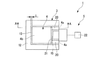
図1及び図2に示すように、本実施形態の圧力センサ1は、所定の周波数帯域の圧力変動を検出するセンサであって、例えばシリコン支持層2a、シリコン酸化膜等の酸化層2b、及びシリコン活性層2cを熱的に張り合わせたSOI基板2を利用して形成され、センサ本体3と、カンチレバー4と、変位測定部5と、を備えている。
Hereinafter, embodiments of a pressure sensor according to the present invention will be described with reference to the drawings.
<Configuration of pressure sensor>
As shown in FIGS. 1 and 2, the
上記センサ本体3は、例えばSOI基板2におけるシリコン支持層2a及び酸化層2bによって、上方に開口する有底筒状に形成されている。センサ本体3の内部空間は、キャビティ(空気室)10として機能し、上方に開口した部分はキャビティ10の内部と外部とを連通する連通開口11として機能する。
なお、図示の例では、センサ本体3は平面視長方形状に形成されているが、この形状に限定されるものではない。
The
In the illustrated example, the
上記カンチレバー4は、センサ本体3の長手方向に沿いながら基端部4aから自由端とされた先端部4bに向けて一方向に延びる板状に形成されており、基端部4aがセンサ本体3に片持ち状に支持された状態で連通開口11の内側に配設されている。
The cantilever 4 is formed in a plate shape extending in one direction from the
より具体的には、このカンチレバー4は、例えばSOI基板2におけるシリコン活性層2cからなり、基端部4aを介してセンサ本体3における周壁部3aの一部の上面に一体的に固定されることで、片持ち支持されている。この際、カンチレバー4のサイズとしては、連通開口11の開口端に近接する平面視長方形状とされており、連通開口11を略閉塞している。これにより、カンチレバー4は、基端部4aを中心としてキャビティ10の内部と外部との圧力差に応じて撓み変形可能とされる。
More specifically, the cantilever 4 is made of, for example, a silicon
なお、センサ本体3における周壁部3aの残りの部分の上面には、SOI基板2におけるシリコン活性層2cからなる枠部12が一体的に固定されている。また、カンチレバー4の外周縁と連通開口11の開口端との間には、カンチレバー4の外周縁に沿って幅Gのギャップ13が平面視コの字状に形成されている。
A
なお、図示の例では、センサ本体3の長手方向側の幅と、短手方向側の幅と、が共に同じ幅Gで形成されたギャップ13を例にしているが、例えば、長手方向側の幅と、短手方向側の幅と、が異なる幅となるようにギャップ13を形成しても良いし、幅寸法が適宜変化するようにギャップ13を形成しても構わない。
この場合、最も幅広とされた部分の幅寸法を幅Gとして、後述する式(1)で用いれば良い。
In the illustrated example, the
In this case, the width dimension of the widest portion may be used as the width G in the expression (1) described later.
カンチレバー4の基端部4aには、平面視コの字状の貫通孔15が形成されており、該カンチレバー4が撓み変形し易い設計とされている。但し、この貫通孔15の形状は、上記形状に限定されるものではない。また、この貫通孔15は、必須なものではなく、形成されていなくても構わない。
The
更に、カンチレバー4の基端部4aには、該カンチレバー4の撓み量(変位量)に応じて抵抗値が変化するピエゾ抵抗20が、貫通孔15をセンサ本体3の短手方向から挟み込むように形成されている。これらピエゾ抵抗20には、導電性材料からなる配線部21が接続されており、この配線部21及びピエゾ抵抗20を含む全体的な形状が平面視U字状とされている。また、ピエゾ抵抗20には、該ピエゾ抵抗20の抵抗値変化に基づいてカンチレバー4の変位を測定する検出回路22が接続されている。
Further, a
これにより、検出回路22を通じて一方のピエゾ抵抗20に所定電圧が印加されると、この電圧印加に起因する電流は、貫通孔15を回り込むようにして、一方のピエゾ抵抗20から配線部21を経由して他方のピエゾ抵抗20に流れる。
そのため、検出回路22は、カンチレバー4の変位(撓み変形)に応じて変化するピエゾ抵抗20の抵抗値変化を電気的な出力信号として取り出すことが可能とされている。従って、この出力信号(センサ出力)に基づいてカンチレバー4の変位を測定でき、圧力変動を検出することが可能となる。
As a result, when a predetermined voltage is applied to one
Therefore, the
なお、上記ピエゾ抵抗20は、例えばリン等のドープ剤(不純物)をイオン注入法や拡散法等の各種の方法によりドーピングされることで形成されている。また、ピエゾ抵抗20及び配線部21上には、図示しない絶縁膜が保護膜として被膜されており、外部との電気的な接触の防止がなされている。
また、上記したピエゾ抵抗20、配線部21及び検出回路22は、カンチレバー4の変位を測定する変位測定部5として機能する。
The
The
(圧力センサの作動)
次に、上述した圧力センサ1を利用して、圧力変動を検出する場合について説明する。
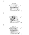
はじめに、図3(A)に示す期間Aのように、キャビティ10の外部の圧力(以下、外気圧Poutと称する)と、キャビティ10の内部の圧力(以下、内気圧Pinと称する)との圧力差がゼロである場合には、図4(A)に示すように、カンチレバー4は撓み変形することがない。
(Pressure sensor operation)
Next, a case where pressure fluctuation is detected using the
First, as in the period A shown in FIG. 3 (A), the external pressure of the cavity 10 (hereinafter, referred to as the outside pressure P out), the pressure in the cavity 10 (hereinafter, referred to as the inner pressure P in) and When the pressure difference is zero, the cantilever 4 does not bend and deform as shown in FIG.
ここで、図3(A)に示す時刻t1以降の期間Bのように、例えば外気圧Poutがステップ状に上昇すると、キャビティ10の外部と内部との間に圧力差が生じるので、図4(B)に示すようにカンチレバー4はキャビティ10の内部に向けて撓み変形する。
すると、カンチレバー4の撓み変形に応じてピエゾ抵抗20に歪が生じ、抵抗値が変化するので、図3(B)に示すように上記出力信号が増大する。
Here, as in the period B after time t1 shown in FIG. 3A, for example, when the external air pressure Pout rises stepwise, a pressure difference is generated between the outside and the inside of the
Then, distortion occurs in the
また、外気圧Poutの上昇以降、ギャップ13を介してキャビティ10の外部から内部へと圧力伝達媒体が流動するので、図3(A)に示すように、内気圧Pinが時間の経過と共に外気圧Poutよりも遅れながら、且つ外気圧Poutの変動よりも緩やかな応答で上昇する。
これにより、内気圧Pinが外気圧Poutに徐々に近づくので、キャビティ10の外部と内部との圧力が均衡状態になりはじめ、カンチレバー4の撓みが徐々に小さくなり、図3(B)に示すように上記出力信号が徐々に低下する。
Further, since increase in the outside air pressure P out, the pressure transmission medium from the outside to the inside of the
Thus, since the inner pressure P in gradually approaches the external atmospheric pressure P out, initially becomes pressure equilibrium between the external and
そして、図3(A)に示す時刻t2以降の期間Cのように、内気圧Pinが外気圧Poutに等しくなると、図4(C)に示すように、カンチレバー4の撓み変形が解消されて元の状態に復帰し、図3(B)に示すように上記出力信号が再びゼロになる。 Then, as in the period C after the time t2 shown in FIG. 3 (A), when the inner pressure P in is equal to the outside pressure P out, as shown in FIG. 4 (C), the flexural deformation of the cantilever 4 is eliminated Then, the original state is restored, and the output signal becomes zero again as shown in FIG.
このように、カンチレバー4の変位に基づいた出力信号の変動をモニタすることで、圧力変動を検出することができる。
特に、SOI基板2のシリコン活性層2cを利用して半導体プロセス技術によりカンチレバー4を形成できるので、従来の圧電素子に比べて薄型化(例えば数十〜数百nm)し易い。従って、微小な圧力変動の検出を精度良く行うことができる。
Thus, by monitoring the fluctuation of the output signal based on the displacement of the cantilever 4, the pressure fluctuation can be detected.
In particular, since the cantilever 4 can be formed by a semiconductor process technique using the silicon
そして、本実施形態の圧力センサ1は、以下の各種用途に適用することができる。
例えば、自動車用ナビゲーション装置に適用することが可能である。この場合、例えば圧力センサ1を利用して高低差に基づく気圧差を検出できるので、高架道路と高架下道路とを正確に判別してナビゲーション結果に反映させることができる。
また、携帯用ナビゲーション装置に適用することも可能である。この場合、例えば圧力センサ1を利用して高低差に基づく気圧差を検出できるので、ユーザが建物内の何階に位置しているのかを正確に判別してナビゲーション結果に反映させることができる。
更には、室内の気圧変化を検出することが可能であるので、例えば建物や自動車の防犯装置に適用することも可能である。
And the
For example, the present invention can be applied to a car navigation device. In this case, for example, the pressure difference based on the height difference can be detected by using the
Further, the present invention can be applied to a portable navigation device. In this case, for example, the pressure difference based on the height difference can be detected by using the
Furthermore, since it is possible to detect a change in the atmospheric pressure in the room, the present invention can be applied to a crime prevention device for a building or an automobile, for example.
このように、圧力センサ1を各種用途に適用することが可能であるが、本実施形態の圧力センサ1によればその用途に応じて、検出することができる圧力変動の周波数帯域(Hz)を予め設定しておくことが可能である。この点、以下に詳細に説明する。
As described above, the
はじめに、上限周波数については、カンチレバー4の最大共振周波数とすることができるので、例えばカンチレバー4のサイズ、材質や厚み等により振動特性を適宜変化させることで、所望する値に設定することが可能である。 First, since the upper limit frequency can be the maximum resonance frequency of the cantilever 4, it can be set to a desired value by appropriately changing the vibration characteristics depending on the size, material, thickness, etc. of the cantilever 4, for example. is there.
次いで、下限周波数の設定について説明する。
まず、ギャップ13の幅Gが大きい場合には、キャビティ10の内部と外部との圧力差が得られ難くなるので、圧力変動の下限周波数が上昇する傾向になる。これに対して、ギャップ13の幅Gが小さい場合には、キャビティ10の内部と外部との圧力差を維持しておき易いので、微小な圧力変動であっても検出し易く、圧力変動の下限周波数が低下する傾向にある。
Next, the setting of the lower limit frequency will be described.
First, when the width G of the
また、キャビティ10の容積Vが小さい場合には、ギャップ13の幅Gが大きい場合と同様に、キャビティ10の内部と外部との圧力差が得られ難くなるので、圧力変動の下限周波数が上昇する傾向になる。これに対して、キャビティ10の容積Vが大きい場合には、ギャップ13の幅Gが小さい場合と同様に、キャビティ10の内部と外部との圧力差を維持しておき易いので、圧力変動の下限周波数が低下する傾向にある。
In addition, when the volume V of the
ここで、本発明者らは、上記した一般的な関係をさらにつきつめて、下限周波数と、ギャップ13の幅Gと、キャビティ10の容積Vと、が下記式(1)の関係式を満たすことを見出した。
Here, the present inventors further investigate the above general relationship, and the lower limit frequency, the width G of the
下限周波数(fLOW )>k・(G2/V)・・・(1)
式中、Gはギャップ13の幅(μm)、Vはキャビティ10の容積(ml)である。また、kは比例定数であって、例えば0.005〜0.02の範囲内で選択される。
Lower limit frequency (f LOW )> k · (G 2 / V) (1)
In the equation, G is the width (μm) of the
これにより、ギャップ13の幅G及びキャビティ10の容積Vの値を変化させるだけの簡便な設計で、従来ではなしえなかった圧力変動の下限周波数を所望する値に設定することが可能となる。
従って、上限周波数及び下限周波数の両方を自在に設定でき、検出することができる圧力変動の周波数帯域を任意に設定することができ、各種の用途に幅広く対応でき、且つ最適な性能を発揮し易い高品質な圧力センサ1とすることができる。
As a result, it is possible to set the lower limit frequency of the pressure fluctuation, which cannot be achieved in the past, to a desired value with a simple design that only changes the value of the width G of the
Therefore, both the upper limit frequency and the lower limit frequency can be freely set, the frequency band of pressure fluctuation that can be detected can be set arbitrarily, can be widely used for various applications, and can easily exhibit optimum performance. A high-
以下、上記式(1)の根拠について、その検証試験結果と共に説明する。
まず、上述したように圧力変動が生じた際、カンチレバー4は撓み変形するが、その変形は、図3からも明らかなように外気圧Poutと内気圧Pinとの差(差圧)に比例する。このとき、外気圧Poutの変動が遅くなるほど(周波数が小さいほど)、カンチレバー4の撓み変形は小さくなると共に、外気圧Poutに対してカンチレバー4の撓み変形の位相が進んで、その位相差は大きくなる。
図5に、外気圧Poutの周波数を変化させた場合における、外気圧Poutと、内気圧Pinと、(外気圧Pout−内気圧Pin)と、の関係を示す。
Hereinafter, the grounds of the above formula (1) will be described together with the verification test results.
First, when the pressure variation as described above occurs, the cantilever 4 is deformed, but the deformation is the difference (differential pressure) between the outside air pressure P out and the inner pressure P in As apparent from FIG. 3 Proportional. At this time, the slower the fluctuation of the external air pressure Pout (the smaller the frequency), the smaller the bending deformation of the cantilever 4, and the phase of the bending deformation of the cantilever 4 advances with respect to the external air pressure Pout . Will grow.
5, in the case of changing the frequency of the outside air pressure P out, and outside air pressure P out, the inner pressure P in, - denoted (outside air pressure P out inner pressure P in), the relationship.
図5に示すように、上記位相差は外気圧Poutの周波数が1Hzの場合が最も小さく、外気圧Poutの周波数が0.5Hz、0.1Hzと小さくなるにつれて大きくなっていることが明らかに認められる。この点は、ギャップ13の幅G及びキャビティ10の容積Vの値に関係なく、共通して認められる現象である。
As shown in FIG. 5, apparent that the phase difference when the frequency of the external atmospheric pressure P out of 1Hz is smallest, is greater as the frequency of the outside air pressure P out 0.5 Hz, smaller and 0.1Hz Recognized. This is a phenomenon that is commonly recognized regardless of the value of the width G of the
次いで、ギャップ13の幅G及びキャビティ10の容積Vの値をそれぞれ変化させた場合における、検証試験結果について、図6〜図13を参照して説明する。
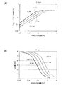
具体的には、ギャップ13の幅G及びキャビティ10の容積Vの値をそれぞれ変化させた場合における、外気圧Poutと、外気圧Poutと内気圧Pinとの差圧(センサ出力)と、の関係について検証を行った。
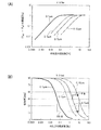
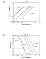
図6〜図13における各図において、
(A)は、外気圧Poutの周波数を変化させた場合における、外気圧Poutと内気圧Pinとの差圧の振幅をプロットしたものであり、
(B)は、外気圧Poutの周波数を変化させた場合における、位相差をプロットしたものである。
Next, verification test results when the width G of the
Specifically, in the case of changing each value of the volume V of the width G and the
In each figure in FIGS.
(A) is, in the case of changing the frequency of the outside air pressure P out, a plot of the amplitude of the pressure difference between the outside air pressure P out and the inner pressure P in,
(B) is a plot of the phase difference when the frequency of the external air pressure Pout is changed.
(検証試験1)
キャビティ10の容積Vを0.5mlとし、ギャップ13の幅Gが1μm、3μm、5μm、10μmとされた4つの圧力センサについて検証試験を行った。この際、外気圧Poutを1.2paで周期的に変動させた。なお、各圧力センサは、ギャップ13の幅Gが異なるだけで、その構成は上記実施形態の圧力センサ1と同一である。
(Verification test 1)
A verification test was performed on four pressure sensors in which the volume V of the
その結果、図6(A)に示すように、ギャップ13の幅Gが小さいほど、検出することができる外気圧Poutの圧力変動の下限周波数が実際に低下することが確認できた。また、図6(B)に示すように、特定の位相差において、外気圧Poutの圧力変動の下限周波数はギャップ13の幅Gの2乗にほぼ比例していることが確認できた。
As a result, as shown in FIG. 6A , it was confirmed that the lower limit frequency of the pressure fluctuation of the external air pressure Pout that can be detected actually decreases as the width G of the
具体的には、図6(B)に示すように、例えば位相差45degとなる下限周波数は、ギャップ13の幅Gが1μmの場合に比べて、10μmの方が100倍程度大きいことが認められる。また、ギャップ13の幅Gが5μmの場合に比べて、10μmの方が4倍程度大きいことが認められる。
Specifically, as shown in FIG. 6B, for example, the lower limit frequency at which the phase difference is 45 deg is recognized to be about 100 times larger in 10 μm than in the case where the width G of the
(検証試験2)
次いで、キャビティ10の容積Vを1mlに変更し、ギャップ13の幅Gが1μm、3μm、5μm、10μmとされた4つの圧力センサについて検証試験を行った。その結果、図7(A)、(B)に示すように、この場合であっても検証試験1と同様の結果を得ることができた。
(Verification test 2)
Next, a verification test was performed on four pressure sensors in which the volume V of the
(検証試験3)
次いで、キャビティ10の容積Vを2mlに変更し、ギャップ13の幅Gが1μm、3μm、5μm、10μmとされた4つの圧力センサについて検証試験を行った。その結果、図8(A)、(B)に示すように、この場合であっても検証試験1と同様の結果を得ることができた。
(Verification test 3)
Next, a verification test was performed on four pressure sensors in which the volume V of the
(検証試験4)
次いで、キャビティ10の容積Vを4mlに変更し、ギャップ13の幅Gが1μm、3μm、5μm、10μmとされた4つの圧力センサについて検証試験を行った。その結果、図9(A)、(B)に示すように、この場合であっても検証試験1と同様の結果を得ることができた。
(Verification test 4)
Next, the verification test was performed on four pressure sensors in which the volume V of the
(検証試験5)
次いで、ギャップ13の幅Gを1μmとし、キャビティ10の容積Vを0.5ml、1ml、2ml、4mlとされた4つの圧力センサについて検証試験を行った。この際、外気圧Poutを1.2paで周期的に変動させた。なお、各圧力センサ1は、ギャップ13の幅Gが異なるだけで、その構成は上記実施形態の圧力センサ1と同一である。
(Verification test 5)
Next, a verification test was performed on four pressure sensors in which the width G of the
その結果、図10(A)に示すように、キャビティ10の容積Vが大きくなるほど、検出することができる外気圧Poutの圧力変動の下限周波数が実際に低下することが確認できた。また、図10(B)に示すように、特定の位相差において、気圧Poutの圧力変動の下限周波数はキャビティ10の容積Vにほぼ反比例していることが確認できた。
As a result, as shown in FIG. 10A, it was confirmed that the lower limit frequency of the pressure fluctuation of the external air pressure Pout that can be detected actually decreases as the volume V of the
具体的には、図10(B)に示すように、例えば位相差45degとなる下限周波数は、キャビティ10の容積Vが4ml、2ml、1ml、0.5mlの順に小さくなるにつれて、それぞれ2倍程度大きくなることが認められる。
Specifically, as shown in FIG. 10B, for example, the lower limit frequency at which the phase difference is 45 deg is about twice as the volume V of the
(検証試験6)
次いで、ギャップ13の幅Gを3μmに変更し、キャビティ10の容積Vが0.5ml、1ml、2ml、4mlとされた4つの圧力センサについて検証試験を行った。その結果、図11(A)、(B)に示すように、この場合であっても検証試験5と同様の結果を得ることができた。
(Verification test 6)
Next, a verification test was performed on four pressure sensors in which the width G of the
(検証試験7)
次いで、ギャップ13の幅Gを5μmに変更し、キャビティ10の容積Vが0.5ml、1ml、2ml、4mlとされた4つの圧力センサについて検証試験を行った。その結果、図12(A)、(B)に示すように、この場合であっても検証試験5と同様の結果を得ることができた。
(Verification test 7)
Next, a verification test was performed on four pressure sensors in which the width G of the
(検証試験8)
次いで、ギャップ13の幅Gを10μmに変更し、キャビティ10の容積Vが0.5ml、1ml、2ml、4mlとされた4つの圧力センサについて検証試験を行った。その結果、図13(A)、(B)に示すように、この場合であっても検証試験5と同様の結果を得ることができた。
(Verification test 8)
Next, a verification test was performed on four pressure sensors in which the width G of the
以上の各検証試験の結果から、圧力変動の下限周波数は、特定の位相差において、ギャップ13の幅Gの2乗に比例し、且つキャビティ10の容積Vに反比例することが認められた。このことにより、上記式(1)を見出すことができた。
From the results of the above verification tests, it has been recognized that the lower limit frequency of pressure fluctuation is proportional to the square of the width G of the
なお、比例定数kは、下限周波数の補正値であり、0.005〜0.02の範囲内で選択されることが好ましい。特に、ギャップ13の幅Gが1μm〜10μmの範囲内で、且つキャビティ10の容積Vが0.5ml〜5mlの範囲内において、下限周波数をより正確に所望する値に設定し易い。
The proportionality constant k is a correction value for the lower limit frequency, and is preferably selected within the range of 0.005 to 0.02. In particular, when the width G of the
なお、本発明の技術範囲は上記実施の形態に限定されるものではなく、本発明の趣旨を逸脱しない範囲において種々の変更を加えることが可能である。 The technical scope of the present invention is not limited to the above embodiment, and various modifications can be made without departing from the spirit of the present invention.
例えば、上記実施形態において、圧力変動の下限周波数を設定する際に、下記式(2)に基づいて設定することが好ましい。
fLOW >k・(G2/V)>fnoise・・・(2)
式中、fnoiseは、ノイズ周波数(Hz)である。
こうすることで、圧力変動の下限周波数をノイズカットしたい周波数よりも高くすることができるので、例えば大気圧変動の影響を受けにくい圧力センサとすることができ、センサとしての価値をさらに高めることができる。
For example, in the above embodiment, when setting the lower limit frequency of pressure fluctuation, it is preferable to set based on the following equation (2).
f LOW > k · (G 2 / V)> f noise (2)
In the formula, f noise is a noise frequency (Hz).
By doing so, the lower limit frequency of pressure fluctuation can be made higher than the frequency at which noise is desired to be cut, so that, for example, a pressure sensor that is not easily affected by atmospheric pressure fluctuation can be obtained, and the value as a sensor can be further increased. it can.
また、上記実施形態では、ピエゾ抵抗20を利用してカンチレバー4の変位を測定する構成としたが、例えば、カンチレバー4に検出光を照射し、その反射光の受光位置に基づいてカンチレバー4の変位を測定する方式(いわゆる光てこ方式)であっても構わない。
但し、上記実施形態のように、ピエゾ抵抗20を利用することで自己変位検出型のカンチレバーとすることができるので、外光等の影響を受けることなく、圧力変動の検出を高精度に行い易い。
In the above embodiment, the displacement of the cantilever 4 is measured using the
However, since the self-displacement detection type cantilever can be obtained by using the
また、上記実施形態において、図14に示すように、レファレンス用のカンチレバー30をさらに備え、検出回路22が2つのカンチレバー4、30の出力の差分を検出するように構成しても構わない。
上記レファレンス用のカンチレバー30は、カンチレバー4と構成が同一とされ、例えばセンサ本体3に一体的に片持ち支持された状態で固定されている。但し、このレファレンス用のカンチレバー30は、外気に対して開放状態とされており、外気圧Poutの圧力変動に起因して撓み変形しない構成とされている。
Further, in the above embodiment, as shown in FIG. 14, a
The
また、この場合の検出回路22は、例えば図15に示すように、ブリッジ回路31(ホイートストンブリッジ回路)と、基準電圧発生回路32と、作動増幅回路33と、出力回路34と、を備えている。
Further, the
ブリッジ回路31は、カンチレバー4のピエゾ抵抗20〔以下、第1ピエゾ抵抗40(抵抗値R1)と称する〕、及び、レファレンス用のカンチレバー30のピエゾ抵抗〔以下、第2ピエゾ抵抗41(抵抗値R2)と称する〕が直列接続されてなる枝辺と、固定抵抗42(抵抗値R3)と固定抵抗43(抵抗値R4)とが直列接続されてなる枝辺と、が基準電圧発生回路32に対して並列に接続されている。
The
なお、ブリッジ回路31において、第1ピエゾ抵抗40と第2ピエゾ抵抗41との接続点は作動増幅回路33の反転入力端子に接続され、固定抵抗42、43同士の接続点は作動増幅回路33の非反転入力端子に接続されている。
In the
基準電圧発生回路32は、ブリッジ回路31に対して所定の基準電圧Vccを印加する。作動増幅回路33は、ブリッジ回路31における2つの固定抵抗42、43同士の接続点と、第1ピエゾ抵抗40と第2ピエゾ抵抗41との接続点と、の間の電位差を検出し、その電位差を所定増幅率にて増幅して出力する。
なお、上記電位差は、第1ピエゾ抵抗40の抵抗値と第2ピエゾ抵抗41の抵抗値との差分(R1−R2)、つまりカンチレバー4と、レファレンス用のカンチレバー30と、の出力の差分に応じた値となる。
The reference
The potential difference depends on the difference between the resistance value of the
このように検出回路22を構成することで、温度変化等の環境変化や、振動等の外乱に起因する出力変動分(ノイズ分)を相殺することができ、外気圧Poutの圧力変動に応じた出力信号だけを取り出すことが可能となる。従って、所望の周波数帯域の圧力変動をさらに精度良く検出することが可能となる。
By thus configuring the
1…圧力センサ
3…センサ本体
4…カンチレバー
4b…カンチレバーの先端部
4a…カンチレバーの基端部
5…変位測定部
10…キャビティ
11…連通開口
20…ピエゾ抵抗
DESCRIPTION OF
Claims (4)
キャビティと、該キャビティの内部と外部とを連通する連通開口と、が形成されたセンサ本体と、
半導体材料により基端部から先端部に向けて一方向に延びる板状に形成され、基端部が前記センサ本体に片持ち状に支持された状態で前記連通開口の内側に配設され、前記キャビティの内部と外部との圧力差に応じて撓み変形するカンチレバーと、
前記カンチレバーの変位を測定する変位測定部と、を備え、
前記カンチレバーの外周縁と前記連通開口の開口端との間には、該カンチレバーの外周縁に沿ってギャップが形成され、
前記周波数帯域における下限周波数fLOW(Hz)は、下記式(1)によって設定されていることを特徴とする圧力センサ。
fLOW >k・(G2/V)・・・(1)
〔式中、kは比例定数、Gは前記ギャップの幅(μm)、Vは前記キャビティの容積(ml)である。〕 A pressure sensor for detecting pressure fluctuations in a predetermined frequency band,
A sensor body in which a cavity and a communication opening for communicating the inside and the outside of the cavity are formed;
It is formed in a plate shape extending in one direction from the base end portion to the tip end portion by a semiconductor material, and the base end portion is disposed inside the communication opening in a state where the base end portion is supported in a cantilevered manner, A cantilever that bends and deforms according to the pressure difference between the inside and outside of the cavity;
A displacement measuring unit for measuring the displacement of the cantilever,
Between the outer periphery of the cantilever and the opening end of the communication opening, a gap is formed along the outer periphery of the cantilever,
The lower limit frequency f LOW (Hz) in the frequency band is set according to the following formula (1).
f LOW > k · (G 2 / V) (1)
[Wherein, k is a proportional constant, G is the width (μm) of the gap, and V is the volume (ml) of the cavity. ]
前記比例定数kは、0.005〜0.02の範囲内とされていることを特徴とする圧力センサ。 The pressure sensor according to claim 1.
The proportionality constant k is in the range of 0.005 to 0.02.
前記下限周波数fLOW は、下記式(2)を満たすことを特徴とする圧力センサ。
fLOW >k・(G2/V)>fnoise・・・(2)
〔式中、fnoiseは、ノイズ周波数(Hz)である。〕 The pressure sensor according to claim 2,
The lower limit frequency f LOW satisfies the following expression (2).
f LOW > k · (G 2 / V)> f noise (2)
[ Where f noise is the noise frequency (Hz). ]
前記変位測定部は、前記カンチレバーの基端部に形成されたピエゾ抵抗を備えることを特徴とする圧力センサ。 The pressure sensor according to any one of claims 1 to 3,
The displacement sensor includes a piezoresistor formed at a proximal end of the cantilever.
Priority Applications (5)
| Application Number | Priority Date | Filing Date | Title |
|---|---|---|---|
| JP2012105306A JP5778619B2 (en) | 2012-05-02 | 2012-05-02 | Pressure sensor |
| EP13785081.4A EP2846143B1 (en) | 2012-05-02 | 2013-03-19 | Pressure sensor |
| CN201380022589.9A CN104272074B (en) | 2012-05-02 | 2013-03-19 | Pressure sensor |
| US14/394,647 US9551621B2 (en) | 2012-05-02 | 2013-03-19 | Pressure sensor having cantilever and displacement measurement unit |
| PCT/JP2013/057765 WO2013164927A1 (en) | 2012-05-02 | 2013-03-19 | Pressure sensor |
Applications Claiming Priority (1)
| Application Number | Priority Date | Filing Date | Title |
|---|---|---|---|
| JP2012105306A JP5778619B2 (en) | 2012-05-02 | 2012-05-02 | Pressure sensor |
Publications (2)
| Publication Number | Publication Date |
|---|---|
| JP2013234853A JP2013234853A (en) | 2013-11-21 |
| JP5778619B2 true JP5778619B2 (en) | 2015-09-16 |
Family
ID=49514328
Family Applications (1)
| Application Number | Title | Priority Date | Filing Date |
|---|---|---|---|
| JP2012105306A Active JP5778619B2 (en) | 2012-05-02 | 2012-05-02 | Pressure sensor |
Country Status (5)
| Country | Link |
|---|---|
| US (1) | US9551621B2 (en) |
| EP (1) | EP2846143B1 (en) |
| JP (1) | JP5778619B2 (en) |
| CN (1) | CN104272074B (en) |
| WO (1) | WO2013164927A1 (en) |
Cited By (5)
| Publication number | Priority date | Publication date | Assignee | Title |
|---|---|---|---|---|
| JP2016125980A (en) * | 2015-01-08 | 2016-07-11 | 国立大学法人 東京大学 | Pressure sensor |
| JP6073512B1 (en) * | 2016-03-10 | 2017-02-01 | 株式会社フジクラ | Differential pressure detection element, flow rate measuring device, and differential pressure detection element manufacturing method |
| CN106716094A (en) * | 2014-10-06 | 2017-05-24 | 国立大学法人东京大学 | Pressure sensor |
| JP2018063224A (en) * | 2016-10-14 | 2018-04-19 | 株式会社フジクラ | Differential pressure detection element and flow rate measurement device |
| JP2020134364A (en) * | 2019-02-21 | 2020-08-31 | セイコーインスツル株式会社 | Pressure sensor, method for driving pressure sensor, and method for carrying pressure sensor |
Families Citing this family (22)
| Publication number | Priority date | Publication date | Assignee | Title |
|---|---|---|---|---|
| US10817096B2 (en) | 2014-02-06 | 2020-10-27 | Apple Inc. | Force sensor incorporated into display |
| EP2954392B1 (en) | 2013-02-08 | 2022-12-28 | Apple Inc. | Force determination based on capacitive sensing |
| US9671889B1 (en) | 2013-07-25 | 2017-06-06 | Apple Inc. | Input member with capacitive sensor |
| JP6294083B2 (en) * | 2014-01-09 | 2018-03-14 | セイコーインスツル株式会社 | Electronics |
| WO2015111581A1 (en) | 2014-01-24 | 2015-07-30 | 国立大学法人 東京大学 | Sensor |
| JP6276867B2 (en) | 2014-02-12 | 2018-02-07 | アップル インコーポレイテッド | Force determination using sheet sensor and capacitive array |
| JP6292932B2 (en) * | 2014-03-13 | 2018-03-14 | セイコーインスツル株式会社 | Pressure sensor |
| JP6350952B2 (en) * | 2014-03-13 | 2018-07-04 | セイコーインスツル株式会社 | Pressure sensor |
| JP6440431B2 (en) * | 2014-03-26 | 2018-12-19 | セイコーインスツル株式会社 | In-vehicle device |
| US10393608B2 (en) | 2014-06-25 | 2019-08-27 | Seiko Instruments Inc. | Pressure change measuring apparatus and pressure change measuring method |
| WO2016047315A1 (en) * | 2014-09-24 | 2016-03-31 | セイコーインスツル株式会社 | Pressure change measurement device, altitude measurement device, and pressure change measurement method |
| JP6474619B2 (en) * | 2015-01-15 | 2019-02-27 | 国立大学法人 東京大学 | Pressure measuring device and pressure measuring method |
| JP6521442B2 (en) * | 2015-06-26 | 2019-05-29 | 国立大学法人 東京大学 | Pressure sensor |
| JP6521441B2 (en) * | 2015-06-26 | 2019-05-29 | 国立大学法人 東京大学 | Pressure sensor |
| US20180164134A1 (en) * | 2015-07-28 | 2018-06-14 | Nazhiyuan Technology (Tangshan), LLC. | Pneumatic sensor in electronic cigarette, device for processing airflow, and electronic cigarette |
| JP2018527592A (en) * | 2015-09-21 | 2018-09-20 | オプセンス ソリューションズ インコーポレイテッド | Optical pressure sensor with reduced mechanical stress |
| US10007343B2 (en) * | 2016-03-31 | 2018-06-26 | Apple Inc. | Force sensor in an input device |
| JP7178229B2 (en) * | 2018-09-27 | 2022-11-25 | セイコーインスツル株式会社 | pulse wave sensor |
| JP7199187B2 (en) * | 2018-09-27 | 2023-01-05 | セイコーインスツル株式会社 | pulse wave sensor |
| JP7166120B2 (en) * | 2018-09-27 | 2022-11-07 | セイコーインスツル株式会社 | Pulse wave sensor and pulse wave measuring method |
| JP7130517B2 (en) * | 2018-09-28 | 2022-09-05 | セイコーインスツル株式会社 | Pulse wave sensor and vibration sensor |
| JP7410707B2 (en) * | 2019-12-23 | 2024-01-10 | セイコーインスツル株式会社 | Flow sensing devices and pump systems |
Family Cites Families (15)
| Publication number | Priority date | Publication date | Assignee | Title |
|---|---|---|---|---|
| DE68926601T2 (en) * | 1988-09-02 | 1997-01-23 | Honda Motor Co Ltd | Semiconductor sensor |
| US5079958A (en) * | 1989-03-17 | 1992-01-14 | Olympus Optical Co., Ltd. | Sensor having a cantilever |
| JPH071215B2 (en) | 1990-10-31 | 1995-01-11 | 住友金属鉱山株式会社 | Air pressure change detector |
| JP2800112B2 (en) * | 1996-02-28 | 1998-09-21 | 株式会社エスアイアイ・アールディセンター | Semiconductor device |
| DE19648424C1 (en) | 1996-11-22 | 1998-06-25 | Siemens Ag | Micromechanical sensor |
| CN1166933C (en) | 2002-12-17 | 2004-09-15 | 林江 | Horizontal polarized sound wave mode adopted resonance type quartz pressure sensor |
| US20050172717A1 (en) * | 2004-02-06 | 2005-08-11 | General Electric Company | Micromechanical device with thinned cantilever structure and related methods |
| DE102006024381B3 (en) * | 2006-05-24 | 2007-12-06 | Fraunhofer-Gesellschaft zur Förderung der angewandten Forschung e.V. | MEMS vacuum sensor based on the friction principle |
| JP4916006B2 (en) | 2007-02-28 | 2012-04-11 | 株式会社山武 | Pressure sensor |
| KR100908124B1 (en) * | 2007-07-09 | 2009-07-16 | 삼성전자주식회사 | Pressure sensor for measuring blood pressure and manufacturing method thereof |
| US8120232B2 (en) * | 2009-01-20 | 2012-02-21 | Palo Alto Research Center Incorporated | Sensors and actuators using piezo polymer layers |
| EP2309241B1 (en) * | 2009-10-07 | 2016-11-30 | ams international AG | MEMS pressure sensor |
| CN102297741B (en) * | 2010-06-25 | 2013-06-05 | 中国科学院电子学研究所 | Silicon resonant air pressure sensor based on Micro-Electro-Mechanical Systems |
| EP2669648A4 (en) | 2011-01-28 | 2017-03-01 | The University of Tokyo | Differential pressure sensor |
| JP5867821B2 (en) * | 2012-03-08 | 2016-02-24 | セイコーインスツル株式会社 | Pressure sensor |
-
2012
- 2012-05-02 JP JP2012105306A patent/JP5778619B2/en active Active
-
2013
- 2013-03-19 WO PCT/JP2013/057765 patent/WO2013164927A1/en active Application Filing
- 2013-03-19 CN CN201380022589.9A patent/CN104272074B/en active Active
- 2013-03-19 EP EP13785081.4A patent/EP2846143B1/en active Active
- 2013-03-19 US US14/394,647 patent/US9551621B2/en active Active
Cited By (10)
| Publication number | Priority date | Publication date | Assignee | Title |
|---|---|---|---|---|
| CN106716094A (en) * | 2014-10-06 | 2017-05-24 | 国立大学法人东京大学 | Pressure sensor |
| JPWO2016056419A1 (en) * | 2014-10-06 | 2017-06-29 | 国立大学法人 東京大学 | Pressure sensor |
| CN106716094B (en) * | 2014-10-06 | 2019-10-25 | 国立大学法人东京大学 | Pressure sensor |
| JP2016125980A (en) * | 2015-01-08 | 2016-07-11 | 国立大学法人 東京大学 | Pressure sensor |
| JP6073512B1 (en) * | 2016-03-10 | 2017-02-01 | 株式会社フジクラ | Differential pressure detection element, flow rate measuring device, and differential pressure detection element manufacturing method |
| WO2017154424A1 (en) * | 2016-03-10 | 2017-09-14 | 株式会社フジクラ | Differential pressure detection element, flow rate measurement device, and method for manufacturing differential pressure detection element |
| US10175073B2 (en) | 2016-03-10 | 2019-01-08 | Fujikura Ltd. | Differential pressure detection element, flow rate measurement device, and method of manufacturing differential pressure detection element |
| JP2018063224A (en) * | 2016-10-14 | 2018-04-19 | 株式会社フジクラ | Differential pressure detection element and flow rate measurement device |
| JP2020134364A (en) * | 2019-02-21 | 2020-08-31 | セイコーインスツル株式会社 | Pressure sensor, method for driving pressure sensor, and method for carrying pressure sensor |
| JP7156969B2 (en) | 2019-02-21 | 2022-10-19 | セイコーインスツル株式会社 | Pressure sensor driving method |
Also Published As
| Publication number | Publication date |
|---|---|
| EP2846143A1 (en) | 2015-03-11 |
| CN104272074A (en) | 2015-01-07 |
| EP2846143B1 (en) | 2021-07-28 |
| CN104272074B (en) | 2016-05-25 |
| US20150096388A1 (en) | 2015-04-09 |
| JP2013234853A (en) | 2013-11-21 |
| WO2013164927A1 (en) | 2013-11-07 |
| EP2846143A4 (en) | 2015-11-11 |
| US9551621B2 (en) | 2017-01-24 |
Similar Documents
| Publication | Publication Date | Title |
|---|---|---|
| JP5778619B2 (en) | Pressure sensor | |
| JP6209801B2 (en) | Pressure sensor | |
| JP5867820B2 (en) | Pressure sensor | |
| US10393608B2 (en) | Pressure change measuring apparatus and pressure change measuring method | |
| JP6144540B2 (en) | Pressure sensor | |
| JP6292932B2 (en) | Pressure sensor | |
| JP5867821B2 (en) | Pressure sensor | |
| Tian et al. | The novel structural design for pressure sensors | |
| US11274983B2 (en) | Electromechanical pressure sensor | |
| JP6184006B2 (en) | Pressure sensor | |
| Tang et al. | An electrothermally excited dual beams silicon resonant pressure sensor with temperature compensation | |
| JP6685766B2 (en) | Pressure change measuring device, altitude measuring device, and pressure change measuring method | |
| Rahman et al. | Analysis of MEMS diaphragm of piezoresistive intracranial pressure sensor | |
| CN104990648B (en) | A kind of pressure sensor and its pressure detection method and pressure-detecting device | |
| JP6985086B2 (en) | Pressure sensor | |
| JP6403007B2 (en) | Pressure sensor | |
| JP6837349B2 (en) | Pressure change measuring device, altitude measuring device, and pressure change measuring method | |
| JP6521442B2 (en) | Pressure sensor | |
| JP6815900B2 (en) | Pressure sensor | |
| JP6521441B2 (en) | Pressure sensor | |
| Je et al. | Surface Micromachined Pressure Sensor with Internal Substrate Vacuum Cavity | |
| Gonzalez Ruiz et al. | Characterization of Poly-SiGe Pressure Sensors | |
| JP2020180847A (en) | Pressure sensor |
Legal Events
| Date | Code | Title | Description |
|---|---|---|---|
| A621 | Written request for application examination |
Free format text: JAPANESE INTERMEDIATE CODE: A621 Effective date: 20150306 |
|
| A131 | Notification of reasons for refusal |
Free format text: JAPANESE INTERMEDIATE CODE: A131 Effective date: 20150401 |
|
| TRDD | Decision of grant or rejection written | ||
| A01 | Written decision to grant a patent or to grant a registration (utility model) |
Free format text: JAPANESE INTERMEDIATE CODE: A01 Effective date: 20150616 |
|
| A61 | First payment of annual fees (during grant procedure) |
Free format text: JAPANESE INTERMEDIATE CODE: A61 Effective date: 20150709 |
|
| R150 | Certificate of patent or registration of utility model |
Ref document number: 5778619 Country of ref document: JP Free format text: JAPANESE INTERMEDIATE CODE: R150 |
|
| R250 | Receipt of annual fees |
Free format text: JAPANESE INTERMEDIATE CODE: R250 |
|
| R250 | Receipt of annual fees |
Free format text: JAPANESE INTERMEDIATE CODE: R250 |
|
| R250 | Receipt of annual fees |
Free format text: JAPANESE INTERMEDIATE CODE: R250 |
|
| R250 | Receipt of annual fees |
Free format text: JAPANESE INTERMEDIATE CODE: R250 |
|
| R250 | Receipt of annual fees |
Free format text: JAPANESE INTERMEDIATE CODE: R250 |
|
| R250 | Receipt of annual fees |
Free format text: JAPANESE INTERMEDIATE CODE: R250 |