JP5776257B2 - Fixing apparatus and image forming apparatus - Google Patents

Fixing apparatus and image forming apparatus Download PDF

Info

Publication number
JP5776257B2
JP5776257B2 JP2011068766A JP2011068766A JP5776257B2 JP 5776257 B2 JP5776257 B2 JP 5776257B2 JP 2011068766 A JP2011068766 A JP 2011068766A JP 2011068766 A JP2011068766 A JP 2011068766A JP 5776257 B2 JP5776257 B2 JP 5776257B2
Authority
JP
Japan
Prior art keywords
pressing
metal plate
longitudinal direction
endless belt
roller
Prior art date
Legal status (The legal status is an assumption and is not a legal conclusion. Google has not performed a legal analysis and makes no representation as to the accuracy of the status listed.)
Active
Application number
JP2011068766A
Other languages
Japanese (ja)
Other versions
JP2012203259A (en
Inventor
誠 淵上
誠 淵上
和敏 御園生
和敏 御園生
Current Assignee (The listed assignees may be inaccurate. Google has not performed a legal analysis and makes no representation or warranty as to the accuracy of the list.)
Fujifilm Business Innovation Corp
Original Assignee
Fuji Xerox Co Ltd
Fujifilm Business Innovation Corp
Priority date (The priority date is an assumption and is not a legal conclusion. Google has not performed a legal analysis and makes no representation as to the accuracy of the date listed.)
Filing date
Publication date
Application filed by Fuji Xerox Co Ltd, Fujifilm Business Innovation Corp filed Critical Fuji Xerox Co Ltd
Priority to JP2011068766A priority Critical patent/JP5776257B2/en
Priority to US13/209,127 priority patent/US8594550B2/en
Priority to CN201110353344.7A priority patent/CN102692856B/en
Publication of JP2012203259A publication Critical patent/JP2012203259A/en
Application granted granted Critical
Publication of JP5776257B2 publication Critical patent/JP5776257B2/en
Active legal-status Critical Current
Anticipated expiration legal-status Critical

Links

Images

Classifications

    • HELECTRICITY
    • H05ELECTRIC TECHNIQUES NOT OTHERWISE PROVIDED FOR
    • H05BELECTRIC HEATING; ELECTRIC LIGHT SOURCES NOT OTHERWISE PROVIDED FOR; CIRCUIT ARRANGEMENTS FOR ELECTRIC LIGHT SOURCES, IN GENERAL
    • H05B3/00Ohmic-resistance heating
    • H05B3/0033Heating devices using lamps
    • H05B3/0038Heating devices using lamps for industrial applications
    • H05B3/0066Heating devices using lamps for industrial applications for photocopying
    • GPHYSICS
    • G03PHOTOGRAPHY; CINEMATOGRAPHY; ANALOGOUS TECHNIQUES USING WAVES OTHER THAN OPTICAL WAVES; ELECTROGRAPHY; HOLOGRAPHY
    • G03GELECTROGRAPHY; ELECTROPHOTOGRAPHY; MAGNETOGRAPHY
    • G03G15/00Apparatus for electrographic processes using a charge pattern
    • G03G15/20Apparatus for electrographic processes using a charge pattern for fixing, e.g. by using heat
    • G03G15/2003Apparatus for electrographic processes using a charge pattern for fixing, e.g. by using heat using heat
    • G03G15/2014Apparatus for electrographic processes using a charge pattern for fixing, e.g. by using heat using heat using contact heat
    • G03G15/206Structural details or chemical composition of the pressure elements and layers thereof

Landscapes

  • Physics & Mathematics (AREA)
  • General Physics & Mathematics (AREA)
  • Fixing For Electrophotography (AREA)

Description

本発明は、定着装置および画像形成装置に関する。   The present invention relates to a fixing device and an image forming apparatus.

特許文献1には、フィルム加熱方式の加熱装置について、加熱体の消費する電力の低減と所定温度までの立ち上げ時間の短縮を図ることを目的とし、固定の加熱体19と、この加熱体を保持する加熱体保持部材14と、前記加熱体19に内面が対向圧接されて移動駆動されるエンドレスの耐熱性フィルム21と、該耐熱性フィルム21の内部に設けられたフィルム案内部材15・16と、前記加熱体19との間に前記フィルム21を挟み込んでニップ部を形成し、そのニップ部におけるフィルム外面との間に導入された、顕画像を支持する記録材をフィルム21を介して加熱体19に圧接させる部材10と、を有し、前記加熱体保持部材14と、前記フィルム案内部材15・16は一体に高耐熱性・高剛性の熱硬化性樹脂で形成されていることが開示されている。   Patent Document 1 discloses a heating device of a film heating method, in order to reduce the power consumed by the heating body and shorten the start-up time to a predetermined temperature. A heating member holding member 14 to be held; an endless heat-resistant film 21 whose inner surface is pressed against and opposed to the heating member 19; and film guide members 15 and 16 provided inside the heat-resistant film 21; The film 21 is sandwiched between the heating body 19 to form a nip portion, and a recording material that supports the visible image introduced between the film 21 and the outer surface of the film in the nip portion is heated through the film 21. The heating body holding member 14 and the film guide members 15 and 16 are integrally formed of a thermosetting resin having high heat resistance and high rigidity. There has been disclosed.

特許文献2には、ウォームアップ時間を短縮するとともに、高い定着性能を得ることを課題とし、加熱部材(30)によりトナー溶融に必要な温度まで加熱される定着ベルト(20)と、定着ベルトの内側に配置され、定着ベルトを加圧ローラに押圧して定着ニップを形成する押圧部材(40)とを備え、押圧部材は表層に樹脂層を有し、内部に気泡を有する一体成形された部材からなり、押圧部材の硬度が加圧ローラの硬度よりも高くしていることが開示されている。   Patent Document 2 aims to shorten the warm-up time and obtain high fixing performance, and includes a fixing belt (20) heated to a temperature necessary for melting the toner by a heating member (30), and a fixing belt. And a pressing member (40) that is disposed inside and presses the fixing belt against the pressure roller to form a fixing nip, and the pressing member has a resin layer as a surface layer and has an air bubble inside. It is disclosed that the hardness of the pressing member is higher than the hardness of the pressure roller.

特許文献3には、定着部材に内包された輻射源からの輻射により定着部材の表面側を直接加熱する定着方式の定着装置において、十分な定着性を得るための加圧力を被定着材に加えることを課題とし、輻射源6・7と、前記輻射源を内包し、少なくとも前記輻射源からの輻射を透過する輻射透過層4a・4bと、前記輻射透過層を透過した輻射を吸収して発熱する輻射吸収層4aとを有する多層構成の定着部材4と、前記定着部材とニップ部Nを形成する対向部材3と、を備え、未定着像Tを形成担持させた被定着材Sを前記ニップ部で挟持搬送しつつ加熱して被定着材上に未定着像を定着させる定着装置において、前記対向部材に対して前記定着部材を前記輻射透過層側から前記ニップ部に圧接せしめる加圧部材7を有することが開示されている。   Japanese Patent Application Laid-Open No. H10-260260 applies a pressing force for obtaining a sufficient fixing property to a fixing material in a fixing type fixing device that directly heats the surface side of the fixing member by radiation from a radiation source included in the fixing member. The problem is that the radiation sources 6 and 7 contain the radiation source, and at least the radiation transmission layers 4a and 4b that transmit the radiation from the radiation source, and the radiation transmitted through the radiation transmission layer is absorbed to generate heat. A fixing member 4 having a multilayer structure having a radiation absorbing layer 4a and a counter member 3 that forms a nip portion N with the fixing member, and a fixing material S on which an unfixed image T is formed and supported is fixed to the nip. In a fixing device for fixing an unfixed image on a material to be fixed while being nipped and conveyed by a portion, a pressure member 7 presses the fixing member against the nip portion from the radiation transmission layer side with respect to the opposing member. Is disclosed to have There.

特許文献4には、低消費電力でウェイトタイムの短縮を可能にし、フルカラー画像のようなトナー量の多い画像の加熱定着に対しても高画質を維持し、かつ高速化にも対応できる等の特長を有する電磁誘導加熱方式の加熱装置を得ることを課題とし、磁場発生手段18・19と、該磁場発生手段の磁場の作用で電磁誘導発熱する部材10と、該電磁誘導発熱性部材と相互圧接して被加熱材Pの加熱ニップ部Nを形成する加圧部材30を有し、電磁誘導発熱性部材の発熱で被加熱材を加熱する加熱装置であり、磁場発生手段は励磁コイル18を有し、該励磁コイルは給電部を除いた部分を絶縁体19で成形被覆した、コイルと絶縁体の一体成形体(絶縁体モールド体)20であり、このコイルと絶縁体の一体成形体20と加圧部材30が電磁誘導発熱性部材10を介して相互圧接して被加熱材Pの加熱ニップ部Nを形成していることが開示されている。   In Patent Document 4, it is possible to reduce the wait time with low power consumption, maintain high image quality even for heat fixing of an image with a large amount of toner such as a full color image, and cope with high speed. An object of the present invention is to obtain a heating device of an electromagnetic induction heating system having features, and the magnetic field generating means 18 and 19, the member 10 that generates electromagnetic induction heat by the action of the magnetic field of the magnetic field generating means, and the electromagnetic induction heat generating member. The heating device includes a pressure member 30 that press-contacts to form a heating nip portion N of the material to be heated P, and heats the material to be heated by the heat generated by the electromagnetic induction heat-generating member. The exciting coil is a coil-insulator integrated molded body (insulator molded body) 20 in which a portion excluding the power feeding portion is molded and covered with an insulator 19, and this coil and insulator integrated molded body 20. And pressure member 30 is electromagnetic induction It was mutually pressed via the exothermic member 10 to form a heating nip portion N of the material to be heated P is disclosed.

特開平6−149104号公報JP-A-6-149104 特開2008−64924号公報JP 2008-64924 A 特開2006−133294号公報JP 2006-133294 A 特開平9−292786号公報JP-A-9-292786

本発明は、無端状ベルトの回転移動を案内する案内部を構成するリブにクラックが生じるのを抑制するようにした定着装置を提供することを目的とする。   SUMMARY OF THE INVENTION An object of the present invention is to provide a fixing device that suppresses occurrence of cracks in a rib that constitutes a guide portion that guides the rotational movement of an endless belt.

本発明の請求項1の定着装置は、熱源を有し、回転可能なローラと、前記ローラに接触し、前記ローラの回転と共に回転移動する無端状ベルトと、長尺な形状を呈し、前記無端状ベルトの内側において長手方向を前記ローラの回転軸方向に向けられて配置される長尺な板材と、長尺の形状を呈し、長手方向を前記板材の短手方向における一端側において前記板材の長手方向に沿って取り付けられ、前記無端状ベルトを前記ローラに押し付ける押付部と、長尺の形状を呈し、長手方向を前記板材の短手方向における他端側において前記板材の長手方向に沿って取り付けられる長尺部と、前記板材の長手方向において間を隔てて設けられ、前記押付部と前記長尺部のいずれか一方に接続され、前記押付部と前記長尺部の他方に向けて延びるが前記他方には接続されない複数のリブと、を備え、前記無端状ベルトの回転移動を案内する案内部と、を有する According to a first aspect of the present invention, there is provided a fixing device having a heat source, a rotatable roller, an endless belt that contacts the roller and rotates with the rotation of the roller, has a long shape, and has the endless shape. A long plate disposed in the inner side of the belt, the longitudinal direction of which is oriented in the rotation axis direction of the roller, and a long shape, and the longitudinal direction of the plate at one end in the short direction of the plate A pressing portion that is attached along the longitudinal direction, presses the endless belt against the roller, and has a long shape, and the longitudinal direction is along the longitudinal direction of the plate material at the other end side in the short direction of the plate material. The long part to be attached and the longitudinal direction of the plate member are provided to be spaced apart from each other, connected to one of the pressing part and the long part, and extended toward the other of the pressing part and the long part. Said Write To and a plurality of ribs are not connected, having a guide portion for guiding the rotational movement of the endless belt.

そして、前記押付部は、長手方向における中央部の厚みが端部の厚みよりも厚く形成されており、前記複数のリブの内、前記押付部の長手方向において中央部に設けられるリブは、前記長尺部に接続され、前記押付部に向けて延びるが前記押付部には接続されないことを特徴とする。 And, the said pressing portion, the thickness of the central portion in the longitudinal direction is formed larger than the thickness of the end portion, of the plurality of ribs, the ribs provided in the central portion in the longitudinal direction of the pressing portion, It is connected to the elongate portion and extends toward the pressing portion, but is not connected to the pressing portion.

本発明の請求項の画像形成装置は、静電潜像が形成される像保持体と、前記像保持体に形成された静電潜像をトナーで現像する現像装置と、前記現像装置によって現像されたトナー像を被転写体に転写する転写装置と、前記被転写体に転写されたトナー像を前記被転写体に定着させるための請求項1記載の定着装置と、を有することを特徴とする。 An image forming apparatus according to a second aspect of the present invention includes an image carrier on which an electrostatic latent image is formed, a developing device that develops the electrostatic latent image formed on the image carrier with toner, and the developing device. a transfer device for transferring the developed toner image to a transfer member, to have a, a fixing device according to claim 1 for fixing a toner image the is transferred to the transfer medium to the transfer object Features.

(削除)   (Delete)

本発明の請求項に記載の定着装置によれば、押付部の長手方向において中央部に設けられるリブを押付部に接続する場合に比べて、押付部の中央部において熱収縮部(ひけ)が生じるのを抑制することができる。 According to the fixing device of the first aspect of the present invention, compared to the case where the rib provided at the central portion in the longitudinal direction of the pressing portion is connected to the pressing portion, the heat shrinking portion (sink) is formed at the central portion of the pressing portion. Can be suppressed.

本発明の請求項に記載の画像形成装置によれば、請求項1記載の定着装置を備えない場合に比べて、定着性が良好な画像形成装置を提供することができる。 According to the image forming apparatus of the second aspect of the present invention, it is possible to provide an image forming apparatus having a good fixing property as compared with the case where the fixing apparatus of the first aspect is not provided.

本発明の実施形態に係る画像形成装置の構成を全体的に示す全体構成図である。1 is an overall configuration diagram illustrating the overall configuration of an image forming apparatus according to an embodiment of the present invention. 本発明の実施形態に係る定着装置の構成を示す断面図である。1 is a cross-sectional view illustrating a configuration of a fixing device according to an embodiment of the present invention. 本発明の実施形態に係る定着装置の押付部材の金属板を示す斜視図である。It is a perspective view which shows the metal plate of the pressing member of the fixing device which concerns on embodiment of this invention. 本発明の実施形態に係る定着装置の押付部材のシート部材を示す斜視図である。FIG. 6 is a perspective view showing a sheet member of a pressing member of the fixing device according to the embodiment of the present invention. 本発明の実施形態に係る定着装置の押付部材を示す斜視図である。FIG. 3 is a perspective view showing a pressing member of the fixing device according to the embodiment of the present invention. 本発明の実施形態に係る定着装置の押付部材を示す図5とは反対側から見た場合の斜視図である。FIG. 6 is a perspective view showing a pressing member of the fixing device according to the embodiment of the present invention when viewed from the side opposite to FIG. 5. 本発明の実施形態に係る定着装置の押付部材の下面図である。It is a bottom view of a pressing member of the fixing device according to the embodiment of the present invention. (A):本発明の実施形態に係る定着装置の押付部材の上面図である。(B)(C):(A)に示す第1のリブ群とは別の形態の第1のリブ群を有する押付部材の上面図である。(A): It is a top view of the pressing member of the fixing device according to the embodiment of the present invention. (B) (C): It is a top view of the pressing member which has the 1st rib group of a form different from the 1st rib group shown to (A). 本発明の実施形態に係る定着装置の押付部材の押付部側から見た場合の側面図である。FIG. 4 is a side view of the fixing device according to the embodiment of the present invention when viewed from the pressing portion side of the pressing member. 本発明の実施形態に係る定着装置の押付部材の長尺部側から見た場合の側面図である。FIG. 5 is a side view of the pressing member of the fixing device according to the embodiment of the present invention when viewed from the long side. (A):本発明の実施形態に係る定着装置の押付部材の比較例としての押付部材を示す斜視図である。(B):その分解斜視図である。(A): It is a perspective view which shows the pressing member as a comparative example of the pressing member of the fixing device which concerns on embodiment of this invention. (B): It is the exploded perspective view. 本発明の実施形態に係る定着装置の押付部材の比較例としての押付部材を用いた場合の定着装置を示す断面図である。FIG. 5 is a cross-sectional view showing a fixing device when a pressing member is used as a comparative example of the pressing member of the fixing device according to the embodiment of the present invention. 本発明の実施形態に係る定着装置の押付部材の比較例として、第1のリブ群の各リブを長尺部と押付部との両方に接続した構成の押付部材において、リブの接続基端に生じるクラックを示す図である。As a comparative example of the pressing member of the fixing device according to the embodiment of the present invention, in the pressing member configured to connect each rib of the first rib group to both the long portion and the pressing portion, the connection base end of the rib It is a figure which shows the crack which arises. 本発明の実施形態に係る定着装置の押付部材の製造に用いられる金型を示す断面図である。It is sectional drawing which shows the metal mold | die used for manufacture of the pressing member of the fixing device which concerns on embodiment of this invention. 図14に示す金型に対してインサート部品としての金属板とシート部材を配置した状態の金型を示す断面図である。It is sectional drawing which shows the metal mold | die of the state which has arrange | positioned the metal plate and sheet | seat member as insert components with respect to the metal mold | die shown in FIG. 図15に示す金型を型締めした場合の状態を示す金型の断面図である。It is sectional drawing of the metal mold | die which shows the state at the time of clamping the metal mold | die shown in FIG. 図16に示す金型を型開きしインサート成形品である押付部材を取り出す状態を示す金型の断面図である。It is sectional drawing of the metal mold | die which shows the state which opens the metal mold | die shown in FIG. 16, and takes out the pressing member which is an insert molded product. 図14に示す金型の挟持部材を主として示す斜視図である。It is a perspective view which mainly shows the clamping member of the metal mold | die shown in FIG. (A)(B):溶融樹脂の流れを示す説明図である。(A) (B): It is explanatory drawing which shows the flow of molten resin. (A):シート部材がインサート成形によって一体化された状態を示す押付部材の断面図である。(B):シート部材が押付部の外方面側に捲れ上がりインサート成形によって一体化されない状態を示す押付部材の断面図である。(A): It is sectional drawing of the pressing member which shows the state with which the sheet | seat member was integrated by insert molding. (B): It is sectional drawing of the pressing member which shows the state which a sheet member rolls up to the outer surface side of a pressing part, and is not integrated by insert molding. インサート成形品である押付部材の製造方法を示すフロー・チャートである。It is a flowchart which shows the manufacturing method of the pressing member which is an insert molded product.

以下、本発明に係る定着装置と、画像形成装置と、定着装置の押付部材を製造するための金型装置と、インサート成形品である押付部材の製造方法の実施形態について、添付の図面に基づいて説明する。   Hereinafter, embodiments of a fixing device, an image forming apparatus, a mold device for manufacturing a pressing member of the fixing device, and a manufacturing method of a pressing member which is an insert molded product according to the present invention will be described with reference to the accompanying drawings. I will explain.

(全体構成)
図1は、本発明の実施形態に係る定着装置を有する画像形成装置の構成の一例を示している。画像形成装置10の装置本体10Aの上下方向を矢印Y方向、左右方向を矢印X方向、奥行き方向を矢印Z方向として記載する。
(overall structure)
FIG. 1 shows an example of the configuration of an image forming apparatus having a fixing device according to an embodiment of the present invention. The vertical direction of the apparatus main body 10A of the image forming apparatus 10 is described as an arrow Y direction, the horizontal direction as an arrow X direction, and the depth direction as an arrow Z direction.

図1に示すように、画像形成装置10の装置本体10Aには、複数のローラ12に張架され、モータ(図示省略)の駆動により矢印A方向に搬送される無端ベルト状の被転写体の一例としての中間転写体ベルト14が設けられている。   As shown in FIG. 1, an image forming apparatus 10 includes an endless belt-shaped transfer body that is stretched around a plurality of rollers 12 and conveyed in the direction of arrow A by driving a motor (not shown). As an example, an intermediate transfer belt 14 is provided.

画像形成装置10は、カラー画像の形成に対応しており、イエロー(Y)、マゼンタ(M)、シアン(C)、ブラック(K)の4色に対応するトナー像を形成する画像形成ユニット28Y、28M、28C、28Kを有している。画像形成ユニット28Y、28M、28C、28Kは、中間転写体ベルト14の搬送方向に沿って配置され、装置本体10Aに脱着可能に支持されている。   The image forming apparatus 10 corresponds to the formation of a color image, and an image forming unit 28Y that forms toner images corresponding to four colors of yellow (Y), magenta (M), cyan (C), and black (K). , 28M, 28C, 28K. The image forming units 28Y, 28M, 28C, and 28K are arranged along the transport direction of the intermediate transfer belt 14, and are detachably supported by the apparatus main body 10A.

尚、各色に設けられた部材については、符号の末尾に各々の色を示すアルファベット(Y/M/C/K)を付与して示す。特に色を区別せずに説明する場合は、この符号末尾のアルファベットを省略する。   In addition, about the member provided in each color, the alphabet (Y / M / C / K) which shows each color is provided to the end of a code | symbol, and is shown. In particular, when the description is made without distinguishing colors, the alphabet at the end of the code is omitted.

各画像形成ユニット28Y、28M、28C、28Kは、図示しないモータ及びギアからなる駆動手段によって時計方向へ回転する像保持体の一例としての感光体ドラム16Y、16M、16C、16Kを備えている。   Each of the image forming units 28Y, 28M, 28C, and 28K includes photosensitive drums 16Y, 16M, 16C, and 16K as an example of an image holding body that is rotated clockwise by a driving unit including a motor and a gear (not shown).

各感光体ドラム16の周面には、感光体ドラム16の表面を一定の電位に一様に帯電させるための帯電ローラ18が配置されている。帯電ローラ18は、導電性のローラであり、その周面が感光体ドラム16の周面に接触し、かつ帯電ローラ18の軸線方向と感光体ドラム16の軸線方向とが平行となるように配置されている。   A charging roller 18 for uniformly charging the surface of the photosensitive drum 16 to a constant potential is disposed on the peripheral surface of each photosensitive drum 16. The charging roller 18 is a conductive roller, and its circumferential surface is in contact with the circumferential surface of the photosensitive drum 16, and is arranged so that the axial direction of the charging roller 18 and the axial direction of the photosensitive drum 16 are parallel to each other. Has been.

各感光体ドラム16の回転方向の帯電ローラ18よりも下流側の周面には、露光装置の一例としてのLEDプリントヘッド(以下、「LPH」という)20が配置されている。LPH20は長尺であり、発光体ドラム16の軸方向に沿って配置されている。LPH20は、LED(発光ダイオード)アレイを光源として有している。LPH20は、画像データに応じて光ビームを感光体ドラム16に照射することにより、感光体ドラム16表面に静電潜像を形成させる。   An LED print head (hereinafter referred to as “LPH”) 20 as an example of an exposure device is disposed on the circumferential surface on the downstream side of the charging roller 18 in the rotation direction of each photosensitive drum 16. The LPH 20 is long and is disposed along the axial direction of the light-emitting drum 16. The LPH 20 has an LED (light emitting diode) array as a light source. The LPH 20 irradiates the photosensitive drum 16 with a light beam according to the image data, thereby forming an electrostatic latent image on the surface of the photosensitive drum 16.

各感光体ドラム16の回転方向のLPH20よりも下流側の周面には、現像装置22が配置されている。現像装置22は、感光体ドラム16表面に形成された静電潜像を各色(イエロー/マゼンタ/シアン/ブラック)のトナーによって現像してトナー像を形成させるためのものである。   A developing device 22 is disposed on the circumferential surface on the downstream side of the LPH 20 in the rotational direction of each photosensitive drum 16. The developing device 22 is for developing the electrostatic latent image formed on the surface of the photosensitive drum 16 with toner of each color (yellow / magenta / cyan / black) to form a toner image.

具体的には、現像装置22は、感光体ドラム16に近接して配置され、回転可能に設けられた円筒状の現像ローラ24を有している。現像ローラ24には、現像バイアスが印加され、現像装置22内に装填されたトナーが周面に付着される。現像ローラ24の回転により、現像ローラ24に付着されたトナーが感光体ドラム16の表面に搬送され、トナーが感光体ドラム16に擦りつけられて、感光体ドラム16表面に形成された静電潜像がトナー像として現像される構成となっている。   Specifically, the developing device 22 includes a cylindrical developing roller 24 that is disposed in the vicinity of the photosensitive drum 16 and is rotatably provided. A developing bias is applied to the developing roller 24, and the toner loaded in the developing device 22 is attached to the peripheral surface. Due to the rotation of the developing roller 24, the toner attached to the developing roller 24 is conveyed to the surface of the photosensitive drum 16, and the toner is rubbed against the photosensitive drum 16 to form an electrostatic latent image formed on the surface of the photosensitive drum 16. The image is developed as a toner image.

各感光体ドラム16の回転方向の現像装置22よりも下流側の周面には、各感光体ドラム16上のトナー像を中間転写体ベルト14に転写する転写装置の一例としての転写ローラ30が設けられている。転写ローラ30は、一定の電位に帯電されると共に、反時計方向に回転して中間転写体ベルト14を一定の速度で搬送し、中間転写体ベルト14を感光体ドラム16に押し付けている。これにより、感光体ドラム16表面のトナー像が中間転写体ベルト14上に転写されるようになっている。   A transfer roller 30 as an example of a transfer device that transfers the toner image on each photoconductive drum 16 to the intermediate transfer belt 14 is disposed on the peripheral surface downstream of the developing device 22 in the rotation direction of each photoconductive drum 16. Is provided. The transfer roller 30 is charged to a constant potential and rotates counterclockwise to convey the intermediate transfer belt 14 at a constant speed, and presses the intermediate transfer belt 14 against the photosensitive drum 16. As a result, the toner image on the surface of the photosensitive drum 16 is transferred onto the intermediate transfer belt 14.

各感光体ドラム16の周面の転写ローラ30よりも下流側の周面には、クリーニングブレード26が配置されている。クリーニングブレード26は、一端が感光体ドラム16の表面に接触するように配設されており、中間転写体ベルト14に転写されずに感光体ドラム16上に残留したトナーや、転写時に感光体ドラム16上に付着してしまった他の色のトナーを削ぎとって回収するものである。   A cleaning blade 26 is disposed on the peripheral surface of each photosensitive drum 16 on the downstream side of the transfer roller 30. The cleaning blade 26 is disposed so that one end thereof is in contact with the surface of the photosensitive drum 16, and toner remaining on the photosensitive drum 16 without being transferred to the intermediate transfer belt 14 or the photosensitive drum at the time of transfer. The toner of the other color that has adhered to 16 is scraped off and collected.

各画像形成ユニット28により形成された各トナー像は、中間転写体ベルト14のベルト面上で、互いに重なり合うように転写される。これにより、中間転写体ベルト14上にカラーのトナー像が形成される。このようにして4色のトナー像が重ねて転写されたトナー像を、以下、「最終トナー像」と称する。   The toner images formed by the image forming units 28 are transferred so as to overlap each other on the belt surface of the intermediate transfer belt 14. As a result, a color toner image is formed on the intermediate transfer belt 14. The toner image onto which the four color toner images are transferred in this manner is hereinafter referred to as a “final toner image”.

4つの感光体ドラム16よりも中間転写体ベルト14の搬送方向下流側には、対向する2つのローラ34A、34Bを含んで構成される二次転写装置34が配設されている。二次転写装置34では、画像形成装置10の底部に設けられた用紙トレイ36から取り出されてローラ34A、34Bの間に搬送されてきた記録用紙Pに、中間転写体ベルト14上に形成された最終トナー像が転写されるようになっている。   A secondary transfer device 34 including two rollers 34 </ b> A and 34 </ b> B facing each other is disposed downstream of the four photosensitive drums 16 in the conveyance direction of the intermediate transfer belt 14. The secondary transfer device 34 is formed on the intermediate transfer belt 14 on the recording paper P taken out from the paper tray 36 provided at the bottom of the image forming apparatus 10 and conveyed between the rollers 34A and 34B. The final toner image is transferred.

最終トナー像が転写された記録用紙Pの搬送経路には、定着装置100が設けられている。定着装置100は加熱ローラ110と加圧ローラ120とを含んで構成されており、定着装置100に搬送された記録用紙Pは加熱ローラ110と加圧ローラ120とによって挟持搬送される。それにより、記録用紙P上のトナーは溶融されると共に記録用紙Pに圧着されて記録用紙Pに定着される。   A fixing device 100 is provided on the conveyance path of the recording paper P onto which the final toner image has been transferred. The fixing device 100 includes a heating roller 110 and a pressure roller 120, and the recording paper P conveyed to the fixing device 100 is nipped and conveyed by the heating roller 110 and the pressure roller 120. As a result, the toner on the recording paper P is melted and pressed onto the recording paper P and fixed on the recording paper P.

一方、中間転写体ベルト14の外周面において、二次転写装置34よりも中間転写体ベルト14の搬送方向下流側には、二次転写装置34によって記録用紙Pに転写されずに中間転写体ベルト14上に残留したトナーを回収するクリーナ装置42が配設されている。クリーナ装置42は、中間転写体ベルト14に接するブレード44を有しており、中間転写体ベルト14上に残留したトナーを擦り取ることによって回収するようになっている。   On the other hand, on the outer peripheral surface of the intermediate transfer body belt 14, the intermediate transfer body belt is not transferred to the recording paper P by the secondary transfer apparatus 34 on the downstream side of the secondary transfer apparatus 34 in the transport direction of the intermediate transfer body 14. A cleaner device 42 for collecting the toner remaining on 14 is disposed. The cleaner device 42 has a blade 44 that contacts the intermediate transfer belt 14 and collects the toner remaining on the intermediate transfer belt 14 by scraping.

上記構成による画像形成装置10では、次のようにして画像が形成される。   In the image forming apparatus 10 configured as described above, an image is formed as follows.

まず、帯電ローラ18によって感光体ドラム16の表面が一様にマイナス帯電される。次いで、帯電された感光体ドラム16表面に対し、LHP20によって印刷すべき画像データに基づいて露光が行われ、感光体ドラム16表面に静電潜像が形成される。   First, the surface of the photosensitive drum 16 is uniformly negatively charged by the charging roller 18. Next, the charged surface of the photosensitive drum 16 is exposed based on image data to be printed by the LHP 20, and an electrostatic latent image is formed on the surface of the photosensitive drum 16.

次いで、感光体ドラム16表面の静電潜像が現像装置22の現像ローラ24を通過すると、静電気力によってトナーが静電潜像に付着し、静電潜像はトナー像として可視化される。   Next, when the electrostatic latent image on the surface of the photosensitive drum 16 passes through the developing roller 24 of the developing device 22, the toner adheres to the electrostatic latent image by electrostatic force, and the electrostatic latent image is visualized as a toner image.

次いで、可視化された各色のトナー像は、転写ローラ30によって中間転写体ベルト14へ順次転写され、中間転写体ベルト14上にカラーの最終トナー像が形成される。   Next, the visualized toner images of the respective colors are sequentially transferred to the intermediate transfer body belt 14 by the transfer roller 30, and a color final toner image is formed on the intermediate transfer body belt 14.

次いで、中間転写体ベルト14上の最終トナー像は二次転写装置34のローラ34A、34Bの間に送り込まれ、用紙トレイ36から取り出されてローラ34A、34Bの間に搬送されてきた記録用紙Pに対してこの最終トナー像が転写される。   Next, the final toner image on the intermediate transfer belt 14 is sent between the rollers 34A and 34B of the secondary transfer device 34, taken out from the paper tray 36, and conveyed between the rollers 34A and 34B. This final toner image is transferred.

次いで、記録用紙Pに転写されたトナー像は定着装置100で定着され、永久画像とされる。定着装置100を通過した記録用紙Pは、装置外へ排出される。   Next, the toner image transferred to the recording paper P is fixed by the fixing device 100 to be a permanent image. The recording paper P that has passed through the fixing device 100 is discharged out of the device.

(定着装置100の構成)
次に、定着装置100の詳細について説明する。
(Configuration of Fixing Device 100)
Next, details of the fixing device 100 will be described.

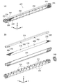
図2に示すように、定着装置100はローラの一例としての加熱ローラ110と加圧ローラ120を備えている。加熱ローラ110は中心部に熱源の一例として例えばハロゲンランプ112を有している。ハロゲンランプ112は、長尺の形状を呈し、長手方向を矢印Z方向に向けられて配置されている。加熱ローラ110のローラ部114は、ハロゲンランプ112から発せられる熱によって加熱される。ローラ部114はモータなどの駆動源(図示省略)によって回転駆動される構成となっている。即ち、加熱ローラ110は熱源を有する回転可能な駆動ローラとして構成されている。   As shown in FIG. 2, the fixing device 100 includes a heating roller 110 and a pressure roller 120 as examples of rollers. The heating roller 110 has, for example, a halogen lamp 112 as an example of a heat source at the center. The halogen lamp 112 has a long shape and is arranged with its longitudinal direction directed in the arrow Z direction. The roller portion 114 of the heating roller 110 is heated by heat generated from the halogen lamp 112. The roller unit 114 is configured to be rotationally driven by a drive source (not shown) such as a motor. That is, the heating roller 110 is configured as a rotatable driving roller having a heat source.

加圧ローラ120は、加熱ローラ110のローラ部114の回転に従動して(ローラ部114の回転と共に)回転移動する無端状ベルト122と、無端状ベルト122の内側に配置されて無端状ベルト122の回転移動を案内すると共に無端状ベルト122を加熱ローラ110に押し付けるための押付部材124とを備えている。   The pressure roller 120 is driven by the rotation of the roller part 114 of the heating roller 110 (with the rotation of the roller part 114), and the endless belt 122 is arranged inside the endless belt 122 and the endless belt 122. And a pressing member 124 for guiding the endless belt 122 against the heating roller 110.

押付部材124は矢印Z方向における両端側に設けられるバネ等の付勢部材(図示省略)によって矢印X方向において加熱ローラ110側に付勢されており、その付勢力によって無端状ベルト122を加熱ローラ110に押し付けている。無端状ベルト122が押付部材124によって加熱ローラ110に押し付けられることで、無端状ベルト122と加熱ローラ110との間には記録用紙Pを挟持搬送しつつトナーを記録用紙Pに定着させるためのニップ部Nが形成される。尚、加熱ローラ110の熱はニップ部Nを介して無端状ベルト122に伝わることとなる。   The pressing member 124 is urged toward the heating roller 110 in the arrow X direction by urging members (not shown) such as springs provided at both ends in the arrow Z direction, and the endless belt 122 is heated by the urging force. 110. When the endless belt 122 is pressed against the heating roller 110 by the pressing member 124, a nip for fixing the toner onto the recording sheet P while nipping and conveying the recording sheet P between the endless belt 122 and the heating roller 110. Part N is formed. The heat of the heating roller 110 is transmitted to the endless belt 122 via the nip portion N.

押付部材124は、無端状ベルト122の回転移動を案内する案内部126と、無端状ベルト122を加熱ローラ110に押し付ける押付部128と、案内部126と押付部128とを保持するための例えば鋼材から構成される板材の一例としての金属板130とを有している。   The pressing member 124 is, for example, a steel material for holding the guide portion 126 that guides the rotational movement of the endless belt 122, the pressing portion 128 that presses the endless belt 122 against the heating roller 110, and the guide portion 126 and the pressing portion 128. And a metal plate 130 as an example of a plate material composed of

図3に示すように、金属板130は矢印Z方向に長手の長尺状を呈すると共に、短手方向(矢印X方向)において片側が直角に折り曲げられており、断面L字状を呈している。金属板130の長手方向における両端側には、長手方向において外方に突出する突出部132が形成されている。前記した付勢部材の一端部は、突出部132に取り付けられている。   As shown in FIG. 3, the metal plate 130 has a long and long shape in the arrow Z direction, and one side is bent at a right angle in the short direction (arrow X direction), and has an L-shaped cross section. . Protruding portions 132 that protrude outward in the longitudinal direction are formed on both ends in the longitudinal direction of the metal plate 130. One end of the biasing member described above is attached to the protrusion 132.

図2に示すように、金属板130の長手方向は加熱ローラ110の回転軸方向(矢印Z方向)に向けられて配置されている。金属板130は短手方向における一端側で押付部128を保持しており、他端側で案内部126を保持している。   As shown in FIG. 2, the longitudinal direction of the metal plate 130 is arranged so as to be directed in the rotation axis direction (arrow Z direction) of the heating roller 110. The metal plate 130 holds the pressing portion 128 on one end side in the short side direction and holds the guide portion 126 on the other end side.

押付部128と無端状ベルト122の内周面との間には、シート部材134が配置されている。シート部材134は例えばポリテトラフルオロエチレン(PTFE)を素材とし、無端状ベルト122のニップNにおける摺動抵抗を低減させるためのものである。   A sheet member 134 is disposed between the pressing portion 128 and the inner peripheral surface of the endless belt 122. The sheet member 134 is made of, for example, polytetrafluoroethylene (PTFE), and is for reducing the sliding resistance at the nip N of the endless belt 122.

図4に示すように、シート部材134は肉薄のシート状を呈しており、可撓性を有している。シート部材134の短手方向(矢印Y方向)の一端側には、複数個(例えば8個)の貫通孔136が長手方向(矢印Z方向)に沿って設けられている。図2に示すように、シート部材134は貫通孔136に通された係止部162(後述)によって押付部128の内方面128aに係止されており、押付部128の外方面128bに沿うように折り返され、その大部分が押付部128と無端状ベルト122の内周面との間に配置されている。   As shown in FIG. 4, the sheet member 134 has a thin sheet shape and has flexibility. On one end side of the sheet member 134 in the short direction (arrow Y direction), a plurality of (for example, eight) through holes 136 are provided along the longitudinal direction (arrow Z direction). As shown in FIG. 2, the sheet member 134 is locked to the inner surface 128 a of the pressing portion 128 by a locking portion 162 (described later) that is passed through the through hole 136, and extends along the outer surface 128 b of the pressing portion 128. The most part is disposed between the pressing portion 128 and the inner peripheral surface of the endless belt 122.

図2、図5、図6に示すように、押付部128は、長尺の形状を呈し、金属板130の短手方向における一端側において長手方向を金属板130の長手方向に沿うようにして取り付けられている。   As shown in FIGS. 2, 5, and 6, the pressing portion 128 has a long shape, and the longitudinal direction is along the longitudinal direction of the metal plate 130 at one end side in the short direction of the metal plate 130. It is attached.

図2〜図10に示すように、案内部126は、金属板130の短手方向における他端側において金属板130の長手方向に沿うように取り付けられる長尺の長尺部138と、長尺部138に接続されて押付部128に向けて延びる複数のリブの一例としての第1のリブ群140と、第1のリブ群140とは金属板130を挟んで反対側に設けられると共に長尺部138に接続されて押付部128に向けて延びる第2のリブ群142と、長尺部138から矢印X方向において押付部128とは反対側の外方に突出する第3のリブ群144とを備えている。   As shown in FIGS. 2 to 10, the guide portion 126 includes a long elongate portion 138 attached along the longitudinal direction of the metal plate 130 on the other end side in the short side direction of the metal plate 130, and a long length. The first rib group 140 as an example of a plurality of ribs connected to the portion 138 and extending toward the pressing portion 128, and the first rib group 140 are provided on the opposite side with the metal plate 130 interposed therebetween and are long. A second rib group 142 connected to the portion 138 and extending toward the pressing portion 128; and a third rib group 144 projecting outward from the long portion 138 on the opposite side of the pressing portion 128 in the arrow X direction; It has.

図5、図6に示すように、押付部128と長尺部138は長手方向(矢印Z方向)における両端側においてサイド部146によって接続されている。サイド部146は矢印Z方向から見た場合において略円形を呈しており、サイド部146の内の一方は、外周から張り出す張出部148を有しており、図2に示すように、無端状ベルト122の矢印Z方向の位置を規定するようになっている。尚、図5、図6に示す押付部材124に対して、無端状ベルト122を他方のサイド部146の側から装着し(無端状ベルト122を装着する際、シート部材134は押付部128の外方面128bに沿うように折り返される)、他方のサイド部146に張出部148と同様な形状を有するキャップ部材(図示省略)を嵌め込むことで、無端状ベルト122が押付部材124から抜け落ちないように構成されている。   As shown in FIGS. 5 and 6, the pressing portion 128 and the long portion 138 are connected by side portions 146 at both ends in the longitudinal direction (arrow Z direction). The side portion 146 has a substantially circular shape when viewed from the direction of the arrow Z, and one of the side portions 146 has an overhanging portion 148 that projects from the outer periphery. As shown in FIG. The position of the belt 122 in the direction of arrow Z is defined. 5 and 6, the endless belt 122 is mounted from the other side portion 146 side (when the endless belt 122 is mounted, the sheet member 134 is attached to the outer side of the pressing portion 128). The endless belt 122 is prevented from falling off the pressing member 124 by fitting a cap member (not shown) having the same shape as the overhanging portion 148 into the other side portion 146. It is configured.

押付部128、長尺部138、第1のリブ群140、第2のリブ群142、第3のリブ群144およびサイド部146は、例えばポリエチレンテレフタレート(PET)などの樹脂材から構成されている。押付部材124は、後述するように、金型304のキャビティ302に金属板130とシート部材134とを入れ込んだ状態で樹脂材(溶融樹脂)を注入することにより、金属板130とシート部材134が樹脂材で一体化されるように形成されたインサート成形品である。   The pressing part 128, the long part 138, the first rib group 140, the second rib group 142, the third rib group 144, and the side part 146 are made of a resin material such as polyethylene terephthalate (PET). . As will be described later, the pressing member 124 injects a resin material (molten resin) in a state where the metal plate 130 and the sheet member 134 are inserted into the cavity 302 of the mold 304, so that the metal plate 130 and the sheet member 134. Is an insert-molded product formed so as to be integrated with a resin material.

図2に示すように、長尺部138の無端状ベルト122の内周面と対向する位置には、不織布(フェルト)150が矢印Z方向に沿って取り付けられている。不織布150には潤滑油が染み込まされており、無端状ベルト122が不織布150に接触しつつ回転移動することで、不織布150から潤滑油が持ち運ばれるようになっている。無端状ベルト122の内周面に潤滑油が行き渡ることにより、無端状ベルト122の摺動抵抗が低減し無端状ベルト122の回転移動が滑らかとなる。   As shown in FIG. 2, a non-woven fabric (felt) 150 is attached along the arrow Z direction at a position facing the inner peripheral surface of the endless belt 122 of the long portion 138. The nonwoven fabric 150 is soaked with lubricating oil, and the endless belt 122 rotates while being in contact with the nonwoven fabric 150, so that the lubricating oil is carried from the nonwoven fabric 150. When the lubricating oil spreads over the inner peripheral surface of the endless belt 122, the sliding resistance of the endless belt 122 is reduced, and the rotational movement of the endless belt 122 becomes smooth.

図2、図6、図8(A)に示すように、第1のリブ群140は、無端状ベルトの回転方向においてニップ部Nよりも下流側に位置し、金属板130の長手方向(矢印Z方向)において間を隔てて設けられる複数個(例えば10個)のリブ152から構成されている。第1のリブ群140の各リブ152は、金属板130から矢印Y方向において張り出すように形成されており、その先端部は無端状ベルト122の回転移動を案内するように矢印Z軸方向から見た場合において円弧状を呈している。第1のリブ群140には、各リブ152同士を連結する連結部154が形成されている。   As shown in FIGS. 2, 6, and 8 (A), the first rib group 140 is located downstream of the nip portion N in the rotational direction of the endless belt, and the longitudinal direction (arrows) of the metal plate 130. It is composed of a plurality of (for example, ten) ribs 152 that are spaced apart in the Z direction. Each rib 152 of the first rib group 140 is formed so as to protrude from the metal plate 130 in the direction of the arrow Y, and its tip end portion extends from the direction of the arrow Z axis so as to guide the rotational movement of the endless belt 122. When viewed, it has an arc shape. In the first rib group 140, a connecting portion 154 that connects the ribs 152 to each other is formed.

第1のリブ群140の各リブ152は、長尺部138に接続されて押付部128に向けて延びるが押付部128には接続されないように構成されている。具体的には、押付部128には第1のリブ群140の各リブ152が接続されないように逃げ溝156が形成されている。   Each rib 152 of the first rib group 140 is configured to be connected to the long portion 138 and extend toward the pressing portion 128, but not connected to the pressing portion 128. Specifically, a relief groove 156 is formed in the pressing portion 128 so that each rib 152 of the first rib group 140 is not connected.

図8(B)に示すように、図8(A)に示す第1のリブ群140の別の形態として、第1のリブ群140の各リブ152を押付部128に接続させ、長尺部138に逃げ溝156を形成して長尺部138に接続されないように構成してもよい。   As shown in FIG. 8 (B), as another form of the first rib group 140 shown in FIG. 8 (A), each rib 152 of the first rib group 140 is connected to the pressing portion 128, and a long portion is formed. A clearance groove 156 may be formed in 138 so as not to be connected to the long portion 138.

このように第1のリブ群140の各リブ152を押付部128と長尺部138のいずれか一方に接続し、他方には接続しない構成とするのは、図13に示すように、第1のリブ群140の各リブ152を押付部128と長尺部138との両方に接続した場合、定着装置100のヒートサイクルにおいて押付部128と長尺部138との熱膨張差による熱歪みが各リブ152に作用し、各リブ152の接続基端にクラック157が生じてしまうためである。   In this way, each rib 152 of the first rib group 140 is connected to one of the pressing portion 128 and the long portion 138 and not connected to the other, as shown in FIG. When the ribs 152 of the rib group 140 are connected to both the pressing portion 128 and the long portion 138, thermal distortion due to the difference in thermal expansion between the pressing portion 128 and the long portion 138 occurs in the heat cycle of the fixing device 100. This is because it acts on the rib 152 and a crack 157 occurs at the connection base end of each rib 152.

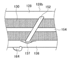
図8(B)に示すように、第1のリブ群140の各リブ152を押付部128に接続する構成とした場合、押付部128の外方面128bの矢印Z方向における中央部のリブ接続箇所に対応する位置には、熱収縮部(ヒケ)158が生じる。これは、押付部128は長手方向(矢印Z方向)における中央部の厚みが端部の厚みよりも厚く形成されており(ここでの厚みは、矢印X方向における厚みをいい、中央部と端部との厚みの差は極僅かであるため、図中では明確に示されていないが、押付部128の外方面128bは中央部で厚み方向おいて凸状に湾曲するようなプロファイルを有している。)、押付部128の外方面128bのリブ接続箇所に対応する位置におけるインサート成形時の熱収縮量が端部よりも中央部の方が多くなるためである。押付部128の外方面128bに熱収縮部158が生じると、無端状ベルト122を加熱ロール110に押し付ける押付力が低下することとなるため、定着装置100の定着性能を低下させる要因となる。   As shown in FIG. 8B, when each rib 152 of the first rib group 140 is connected to the pressing portion 128, the rib connecting portion in the central portion in the arrow Z direction of the outer surface 128b of the pressing portion 128 is used. A thermal contraction (sink) 158 is generated at a position corresponding to. This is because the pressing portion 128 is formed such that the thickness of the central portion in the longitudinal direction (arrow Z direction) is thicker than the thickness of the end portion (the thickness here refers to the thickness in the arrow X direction; Although the difference in thickness with the portion is very small, it is not clearly shown in the figure, but the outer surface 128b of the pressing portion 128 has a profile that curves in a convex shape in the thickness direction at the center portion. This is because the amount of heat shrinkage at the time of insert molding at the position corresponding to the rib connecting portion of the outer surface 128b of the pressing portion 128 is larger in the center portion than in the end portion. If the heat contraction portion 158 is generated on the outer surface 128b of the pressing portion 128, the pressing force for pressing the endless belt 122 against the heating roll 110 is reduced, which causes a reduction in fixing performance of the fixing device 100.

押付部128の外方面128bに熱収縮部158を生じさせないためには、第1のリブ群140の各リブ152の接続態様は、図8(B)に示す接続態様よりも図8(A)に示す接続態様の方が望ましい。尚、図8(C)に示すように、第1のリブ群140の各リブ152の内、中央部のリブ152のみを長尺部138に接続して押付部128に接続しない接続態様としてもよい。   In order not to generate the heat shrinkage part 158 on the outer surface 128b of the pressing part 128, the connection mode of the ribs 152 of the first rib group 140 is shown in FIG. 8A rather than the connection mode shown in FIG. 8B. The connection mode shown in FIG. As shown in FIG. 8C, a connection mode in which only the central rib 152 of the first ribs 140 in the first rib group 140 is connected to the long portion 138 and is not connected to the pressing portion 128 is also possible. Good.

図2、図5、図7に示すように、第2のリブ群142は、金属板130の長手方向(矢印Z方向)において間を隔てて設けられる複数個(例えば12個)のリブ160から構成されている。第2のリブ群142の各リブ160は、金属板130から矢印Y方向において張り出すように形成されており、その先端部は無端状ベルト122の回転移動を案内するように矢印Z軸方向から見た場合において円弧状を呈している。   As shown in FIGS. 2, 5, and 7, the second rib group 142 includes a plurality of (for example, twelve) ribs 160 that are spaced apart in the longitudinal direction (the arrow Z direction) of the metal plate 130. It is configured. Each rib 160 of the second rib group 142 is formed so as to protrude from the metal plate 130 in the direction of the arrow Y, and the tip portion thereof extends from the direction of the arrow Z axis so as to guide the rotational movement of the endless belt 122. When viewed, it has an arc shape.

12個のリブ160の内の矢印Z方向における中央寄りの4個のリブ160は、長尺部138に接続されて押付部128に向けて延びるが押付部128には接続されていない。残りの両端寄りの8個のリブ160は、長尺部138に接続されて押付部128に向けて延び、柱状の係止部162を通じて押付部128に接続されている。各係止部162はシート部材134の対応する各貫通孔136に通されており、シート部材134は各リブ160と押付部128の内方面128aとの間から抜けないようになっている。別言すれば、押付部材124は、シート部材134の短手方向における一端部が第2のリブ群142の各リブ160と押付部128との間で保持されるようにインサート成形されている。   Of the twelve ribs 160, the four ribs 160 closer to the center in the arrow Z direction are connected to the long portion 138 and extend toward the pressing portion 128, but are not connected to the pressing portion 128. The remaining eight ribs 160 near both ends are connected to the long portion 138 and extend toward the pressing portion 128, and are connected to the pressing portion 128 through a columnar locking portion 162. Each locking portion 162 is passed through each corresponding through hole 136 of the sheet member 134, and the sheet member 134 is prevented from coming off between each rib 160 and the inner surface 128 a of the pressing portion 128. In other words, the pressing member 124 is insert-molded such that one end portion of the sheet member 134 in the short direction is held between each rib 160 of the second rib group 142 and the pressing portion 128.

第2のリブ群142において中央寄りの4個のリブ160に係止部162を設けないようにしたのは、図8(B)に関して説明したように、押付部128の外方面128bに熱収縮部(ヒケ)158を生じさせないようにするためである。   In the second rib group 142, the four ribs 160 closer to the center are not provided with the locking portions 162 because the outer surface 128b of the pressing portion 128 is thermally contracted as described with reference to FIG. This is to prevent the generation of the part (sink) 158.

図2、図10に示すように、第3のリブ群144は、長尺部138の長手方向(矢印Z方向)において間を隔てて設けられる複数個(例えば12個)のリブ164から構成されている。第3のリブ群144の各リブ164の先端部は無端状ベルト122の回転移動を案内するように矢印Z軸方向から見た場合において円弧状を呈している。   As shown in FIGS. 2 and 10, the third rib group 144 is composed of a plurality of (for example, twelve) ribs 164 provided at an interval in the longitudinal direction (arrow Z direction) of the long portion 138. ing. The tip of each rib 164 of the third rib group 144 has an arc shape when viewed from the arrow Z-axis direction so as to guide the rotational movement of the endless belt 122.

尚、図10に示すように、第1のリブ群140と第2のリブ群142と第3のリブ群144の各リブ152、160、164は、長手方向の中央に対して対称に形成され、無端状ベルト122の回転方向Bを上向きとして見た場合に、「ハ」の字状に形成されている。これは、無端状ベルト122の内側において無端状ベルト122の回転移動によって潤滑油が矢印Z方向における中央に寄るようにし、潤滑油がサイド部146における隙間から漏れ出すのを抑制するためである。   As shown in FIG. 10, the ribs 152, 160, 164 of the first rib group 140, the second rib group 142, and the third rib group 144 are formed symmetrically with respect to the center in the longitudinal direction. When the rotation direction B of the endless belt 122 is viewed upward, the endless belt 122 is formed in a “C” shape. This is to prevent the lubricating oil from leaking from the gap in the side portion 146 by causing the lubricating oil to move toward the center in the arrow Z direction due to the rotational movement of the endless belt 122 inside the endless belt 122.

図11(A)は、図5などに示す本実施形態の押付部材124に対する比較例としての押付部材224を示す斜視図である。図11(B)は、その分解斜視図である。図12は、比較例としての押付部材224を有する定着装置200を示す図2と同様な断面図である。   FIG. 11A is a perspective view showing a pressing member 224 as a comparative example with respect to the pressing member 124 of the present embodiment shown in FIG. 5 and the like. FIG. 11B is an exploded perspective view thereof. FIG. 12 is a cross-sectional view similar to FIG. 2 showing a fixing device 200 having a pressing member 224 as a comparative example.

図11(B)に示すように、押付部材224はインサート成形品ではなく、案内部226と押付部228とサイド部246と金属板230とシート部材234とは別部品として構成されており、これら5部品を組み立てることで形成される集合部品である。   As shown in FIG. 11B, the pressing member 224 is not an insert molded product, and the guide portion 226, the pressing portion 228, the side portion 246, the metal plate 230, and the sheet member 234 are configured as separate parts. It is a collective part formed by assembling five parts.

押付部材224の案内部226は断面U字状の箱型を呈する形状を有しており、その外周面に無端状ベルト122の内周面と接触するリブ222が複数形成されている。金属板230は案内部226の内部に収容されるように組み立てられている。シート部材234は、その一端部に設けられる貫通孔236が押付部228に設けられた係止部262に通されることで、押付部228に取り付けられている。   The guide portion 226 of the pressing member 224 has a box shape with a U-shaped cross section, and a plurality of ribs 222 that contact the inner peripheral surface of the endless belt 122 are formed on the outer peripheral surface thereof. The metal plate 230 is assembled so as to be accommodated in the guide portion 226. The sheet member 234 is attached to the pressing portion 228 by passing a through hole 236 provided at one end thereof through a locking portion 262 provided in the pressing portion 228.

押付部材224の案内部226とサイド部246の片側はポリエチレンテレフタレート(PET)などの樹脂材から構成されているが、押付部228は例えば液晶ポリマー(LCP)といったポリエチレンテレフタレート(PET)に比較して強度の高い材料から構成されている。押付部材224の押付部228に高強度の材料が用いられるのは、押付部228に曲げ剛性が要求されるためである。   One side of the guide part 226 and the side part 246 of the pressing member 224 is made of a resin material such as polyethylene terephthalate (PET), but the pressing part 228 is, for example, in comparison with polyethylene terephthalate (PET) such as liquid crystal polymer (LCP). Consists of high strength materials. The reason why the high-strength material is used for the pressing portion 228 of the pressing member 224 is that bending rigidity is required for the pressing portion 228.

これに対し、本実施形態の押付部材124では、押付部128をポリエチレンテレフタレート(PET)から構成しているが、案内部126と押付部128とサイド部146と金属板130がインサート成形によって一体化されることで、押付部128は十分な曲げ剛性を有するものとなっている。   On the other hand, in the pressing member 124 of the present embodiment, the pressing portion 128 is made of polyethylene terephthalate (PET), but the guide portion 126, the pressing portion 128, the side portion 146, and the metal plate 130 are integrated by insert molding. As a result, the pressing portion 128 has sufficient bending rigidity.

図2と図12とを参照しつつ本実施形態の押付部材124と比較例としての押付部材224とを対比して説明すると、押付部材124では、案内部126が、長尺部138から矢印Z方向において間隔をおいて立脚される第1のリブ群140と第2のリブ群142を有しているので、金属板130はその大部分において無端状ベルト122の内周面と向い合うようになっている。別言すれば、押付部材124は、金属板130と無端状ベルト122の内周面とが向い合う部分(図7、図8(A)で示す露出部分166)を有するようにインサート成形されている。   The pressing member 124 of this embodiment and the pressing member 224 as a comparative example will be described with reference to FIG. 2 and FIG. 12. In the pressing member 124, the guide portion 126 is moved from the long portion 138 to the arrow Z. Since the first rib group 140 and the second rib group 142 are erected at intervals in the direction, the metal plate 130 faces most of the inner peripheral surface of the endless belt 122. It has become. In other words, the pressing member 124 is insert-molded so as to have a portion (the exposed portion 166 shown in FIGS. 7 and 8A) where the metal plate 130 and the inner peripheral surface of the endless belt 122 face each other. Yes.

金属板130と無端状ベルト122の内周面とが相対する部分では、図2中の矢印Cで示すように、無端状ベルト122からの輻射熱は金属板130の表面で反射され無端状ベルト122に戻されるといったリフレクター効果が生じる。このため、無端状ベルト122において加熱ロール110からの熱が無駄に損失されるのが抑制される。即ち、リフレクター効果により、無端状ベルト122の熱は有効利用されることとなる。これに対して押付部材224では、図12に示すように、案内部226が断面U字状の箱型に形成され金属板230を内部に収容するように構成されていることから、矢印Z方向において金属板230が無端状ベルト122の内周面と相対する部分を有さない。そのため、押付部材224ではリフレクター効果が生じることがない。   At a portion where the metal plate 130 and the inner peripheral surface of the endless belt 122 face each other, the radiant heat from the endless belt 122 is reflected by the surface of the metal plate 130 as indicated by an arrow C in FIG. This creates a reflector effect that returns to For this reason, in the endless belt 122, it is suppressed that the heat from the heating roll 110 is lost vainly. That is, the heat of the endless belt 122 is effectively used due to the reflector effect. On the other hand, in the pressing member 224, as shown in FIG. 12, the guide portion 226 is formed in a box shape having a U-shaped cross section and is configured to accommodate the metal plate 230 therein. The metal plate 230 does not have a portion facing the inner peripheral surface of the endless belt 122. Therefore, the pressing member 224 does not produce a reflector effect.

また、押付部材124では、図2中の矢印Dで示すように、不織布150から供給される潤滑油の大部分は、シート部材134と無端状ベルト122が接触する位置で掻き取られて不織布150に戻されるようになっている。これに対して押付部材224では、図12中の矢印Eで示すように、シート部材234と無端状ベルト122が接触する位置で掻き取られた潤滑油が案内部236の内部に入り込み、不織布150に戻らない潤滑油が生じるため、潤滑油の利用率が低下することとなる。   In the pressing member 124, as indicated by an arrow D in FIG. 2, most of the lubricating oil supplied from the nonwoven fabric 150 is scraped off at a position where the sheet member 134 and the endless belt 122 come into contact, and the nonwoven fabric 150. It is supposed to be returned to. On the other hand, in the pressing member 224, as indicated by an arrow E in FIG. 12, the lubricating oil scraped off at the position where the sheet member 234 and the endless belt 122 are in contact enters the inside of the guide portion 236, and the nonwoven fabric 150 As a result, there is a lubricant that does not return to, so the utilization factor of the lubricant is reduced.

さらに、押付部材124で使用される樹脂量は、押付部材224に使用される樹脂量に比べて約23%低減されている。また、押付部材224の押付部228には高価な液晶ポリマー(LCP)を用いている。即ち、押付部材124は押付部材224に比べると材料費において低コストとなっている。   Further, the amount of resin used in the pressing member 124 is reduced by about 23% compared to the amount of resin used in the pressing member 224. Further, an expensive liquid crystal polymer (LCP) is used for the pressing portion 228 of the pressing member 224. That is, the pressing member 124 is lower in material cost than the pressing member 224.

また、押付部材224では、5部品を組み立てるための作業を要するが、押付部材124では、案内部126、押付部128、サイド部146およびインサート部品としての金属板130とシート部材134とを一体的に成形しているため、組み立て作業を要しない。即ち、押付部材124は押付部材224に比べると組立費において低コストとなっている。   Further, in the pressing member 224, an operation for assembling five parts is required, but in the pressing member 124, the guide part 126, the pressing part 128, the side part 146, the metal plate 130 as the insert part, and the sheet member 134 are integrated. Because it is molded in, no assembly work is required. That is, the pressing member 124 is lower in assembly cost than the pressing member 224.

本実施形態の押付部材124の構成について付言すると、図2に示すように、加熱ローラ110と無端状ベルト122の回転の方向が見える横断面から見た場合において、金属板130の矢印X方向を向く部分の中心線L1は、加熱ローラ110の回転中心と無端状ベルト122の回転中心とを含む中心線L2から矢印Y方向に片寄った(オフセットした)位置に設けられている。これは、ニップ部Nを通過した記録用紙Pの自己剥離性を向上させるべく、ニップ部Nの記録用紙Pの搬送方向における中央部よりも下流側で最も強く押付力を付与しており、この最も強い押付力を付与する位置に金属板130を配置することで、押付部128に曲がりが生じるのを抑制するためである。   If it adds about the structure of the pressing member 124 of this embodiment, when it sees from the cross section which can see the direction of rotation of the heating roller 110 and the endless belt 122, as shown in FIG. 2, the arrow X direction of the metal plate 130 is shown. The center line L1 of the facing portion is provided at a position offset (offset) in the arrow Y direction from the center line L2 including the rotation center of the heating roller 110 and the rotation center of the endless belt 122. In order to improve the self-peeling property of the recording paper P that has passed through the nip portion N, the pressing force is most strongly applied on the downstream side of the central portion in the conveyance direction of the recording paper P in the nip portion N. This is because the bending of the pressing portion 128 is suppressed by arranging the metal plate 130 at a position where the strongest pressing force is applied.

一方、金属板130を挟んで存在する両側の樹脂量が均等でない場合、インサート成形における樹脂材の熱収縮量に差に起因して金属板130に反りが生じるため、第1のリブ群140に連結部154を設け、金属板130の中心線L2からオフセットした側の樹脂量を補うようにしている。即ち、押付部材124では、第1のリブ群140に連結部154を設けることで、金属板130の中心線L1を挟んで存在する両側の樹脂材の量が均等となるようにし、金属板130に反りが生じるのを抑制するように構成している。ここで、「金属板130を挟んで存在する両側(金属板130の両側)」は、金属板130を構成する複数の平面の内、面積の最も大きい平面の外側と、当該面積の最も大きい平面と対向する平面の外側であるとも言える。   On the other hand, if the amount of resin on both sides of the metal plate 130 is not uniform, the metal plate 130 is warped due to a difference in the amount of thermal shrinkage of the resin material in the insert molding. A connecting portion 154 is provided to compensate for the amount of resin on the side offset from the center line L2 of the metal plate 130. That is, in the pressing member 124, the first rib group 140 is provided with the connecting portion 154 so that the amount of the resin material on both sides across the center line L 1 of the metal plate 130 is equalized. It is configured to suppress the occurrence of warpage. Here, “both sides present on both sides of the metal plate 130 (both sides of the metal plate 130)” are the outside of the plane having the largest area and the plane having the largest area among the plurality of planes constituting the metal plate 130. It can also be said that it is outside the plane opposite to.

(金型装置)
次に、インサート成形品である押付部材124の製造に用いられる金型装置300について図14〜図20を用いて説明する。金型装置300の上下方向を矢印y方向、左右方向を矢印x方向、奥行き方向を矢印z方向として記載する。
(Molding equipment)
Next, a mold apparatus 300 used for manufacturing the pressing member 124 that is an insert-molded product will be described with reference to FIGS. The vertical direction of the mold apparatus 300 is described as an arrow y direction, the horizontal direction as an arrow x direction, and the depth direction as an arrow z direction.

図14〜図17に示すように、金型装置300は、断面視において略円筒状を呈すると共に矢印z方向に長尺なキャビティ302を有する金型304を備えている。金型304は、装置の基台(図示省略)に固定される固定側金型306と、矢印x方向に可動する可動側金型308とを有している。金型304の外部には、固定側金型306と可動側金型308とに接続されて固定側金型306と可動側金型308と加熱するための加熱装置310が設けられている。ここで、加熱装置310とは、媒体(水、油等)を介して、金型304および挟持部材318を予め定められた温度に温度コントロールする温度調整装置(温度コントローラ)のことである。   As shown in FIGS. 14 to 17, the mold apparatus 300 includes a mold 304 that has a substantially cylindrical shape in a sectional view and has a cavity 302 that is long in the arrow z direction. The mold 304 has a fixed side mold 306 that is fixed to a base (not shown) of the apparatus, and a movable side mold 308 that is movable in the arrow x direction. A heating device 310 for heating the fixed side mold 306 and the movable side mold 308 connected to the fixed side mold 306 and the movable side mold 308 is provided outside the mold 304. Here, the heating device 310 is a temperature adjusting device (temperature controller) that controls the temperature of the mold 304 and the holding member 318 to a predetermined temperature via a medium (water, oil, or the like).

固定側金型306には、射出機(図示省略)から射出された溶融樹脂(樹脂材)をキャビティに注入するための注入口312が設けられている。注入口312は、固定側金型306の矢印z方向における一端側のキャビティ302を臨む位置に1個設けられている。   The fixed mold 306 is provided with an injection port 312 for injecting molten resin (resin material) injected from an injection machine (not shown) into the cavity. One inlet 312 is provided at a position facing the cavity 302 on one end side in the arrow z direction of the fixed mold 306.

固定側金型306には、その壁面にシート部材134を吸引して固定するための吸引口314が設けられている。吸引口314は、矢印z方向に沿って間を隔てて複数個設けられおり(図中では1個のみ示す)、シート部材134は、その長手方向を矢印z方向に向けられると共に、その短手方向(矢印y方向)における一端部がキャビティ302に挿入されるように固定側金型306に吸引固定される。   The stationary mold 306 is provided with a suction port 314 for sucking and fixing the sheet member 134 to the wall surface thereof. A plurality of suction ports 314 are provided at intervals along the arrow z direction (only one is shown in the figure), and the sheet member 134 has its longitudinal direction oriented in the arrow z direction and its short side. One end in the direction (arrow y direction) is sucked and fixed to the fixed mold 306 so as to be inserted into the cavity 302.

可動側金型308には、金属板130をキャビティ302内で位置決めするための位置決め溝316(図14、図17参照)が設けられている。位置決め溝316は、可動側金型308の矢印z方向における両端側にそれぞれ1個ずつ設けられている(図14、図17では1個のみ示す)。   The movable mold 308 is provided with a positioning groove 316 (see FIGS. 14 and 17) for positioning the metal plate 130 in the cavity 302. One positioning groove 316 is provided on each of both end sides in the arrow z direction of the movable mold 308 (only one is shown in FIGS. 14 and 17).

図14、図15に示すように、金属板130は、その長手方向をキャビティ302の長手方向(矢印z方向)に向けられ、位置決め溝316に金属板130の突出部132を嵌め入れることによってキャビティ302内において位置決めされる。   As shown in FIGS. 14 and 15, the metal plate 130 has its longitudinal direction oriented in the longitudinal direction (arrow z direction) of the cavity 302, and the protrusion 132 of the metal plate 130 is fitted into the positioning groove 316. Positioned within 302.

可動側金型308には、矢印y方向に可動自在な挟持部材318が設けられている。挟持部材318は上部可動コア320と下部可動コア322から構成されており、図15に示すように、上部可動コア320と下部可動コア322はそれぞれ可動側金型308の型締め方向Fへの移動に連動して金属板130を挟持する挟持方向Gに移動するようになっている。また、図17に示すように、上部可動コア320と下部可動コア322はそれぞれ可動側金型308の型開き方向Hへの移動に連動して金属板130を挟持しない非挟持方向Iに移動するようになっている。   The movable mold 308 is provided with a clamping member 318 that is movable in the direction of the arrow y. The sandwiching member 318 includes an upper movable core 320 and a lower movable core 322. As shown in FIG. 15, the upper movable core 320 and the lower movable core 322 move in the mold clamping direction F of the movable mold 308, respectively. It moves to the clamping direction G which clamps the metal plate 130 in conjunction with. Further, as shown in FIG. 17, the upper movable core 320 and the lower movable core 322 move in the non-clamping direction I where the metal plate 130 is not clamped in conjunction with the movement of the movable mold 308 in the mold opening direction H. It is like that.

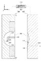
図16に示すように、金属板130は、キャビティ302の横断面(キャビティ302の短手方向断面)から見た場合において、キャビティ302の中心からオフセットした位置において挟持部材318によって挟持される。ここで、キャビティ302の中心を別言すると、キャビティ302内でインサート成形されたインサート成形品(押付部材124)に無端状ベルト122を装着したと仮定した場合に、当該無端状ベルト122の回転中心(設計値)のことである。樹脂材は、挟持部材318によって金属板130を挟持した状態でキャビティ302に注入される。前述したように、インサート成形における樹脂材の熱収縮量に差に起因して金属板130に反りが生じるのを抑制するため、キャビティ302において金属板130を挟んで存在する両側の樹脂材の量が均等となるように固定側金型306と可動側金型308と上部可動コア320と下部可動コア322の形状が決定されている。   As shown in FIG. 16, the metal plate 130 is sandwiched by the sandwiching member 318 at a position offset from the center of the cavity 302 when viewed from the cross section of the cavity 302 (cross section of the cavity 302 in the short direction). Here, in other words, when the endless belt 122 is assumed to be attached to an insert molded product (pressing member 124) insert-molded in the cavity 302, the center of rotation of the endless belt 122 will be described. (Design value). The resin material is injected into the cavity 302 with the metal plate 130 held between the holding members 318. As described above, in order to suppress the warpage of the metal plate 130 due to the difference in the heat shrinkage amount of the resin material in the insert molding, the amount of the resin material on both sides existing between the metal plate 130 in the cavity 302. The shapes of the fixed side mold 306, the movable side mold 308, the upper movable core 320, and the lower movable core 322 are determined so as to be uniform.

具体的には、図18に示すように、上部可動コア320と下部可動コア322にはそれぞれ、第1のリブ群140と第2のリブ群142を形成するためのリブ用溝324が形成されており、上部可動コア320には、さらに連結部154を形成するための連結部用溝326が形成されている。連結部用溝326を設けることにより、キャビティ302において金属板130を挟んで存在する両側の樹脂材の量が均等とされるようになっている。   Specifically, as shown in FIG. 18, rib grooves 324 for forming the first rib group 140 and the second rib group 142 are formed in the upper movable core 320 and the lower movable core 322, respectively. The upper movable core 320 is further provided with a connecting portion groove 326 for forming a connecting portion 154. By providing the connecting portion groove 326, the amount of the resin material on both sides of the cavity 302 with the metal plate 130 interposed therebetween is made equal.

図18に示すように、上部可動コア320と下部可動コア322はそれぞれ、リブ用溝324によってキャビティ302の長手方向(矢印z方向)において分割された複数の挟持部328によって金属板130を挟持する構成となっている(上部可動コア320は、さらに連結部用溝326によって短手方向(矢印x方向)においても分割されている)。また、上部可動コア320と下部可動コア322の挟持部328は、金属板130を押し切る(金属板130の厚みを縮小させる)ように金属板130を挟持するように構成されている。別言すれば、金型304を型締めする際、上部可動コア320と下部可動コア322の挟持方向Gの移動量が、金属板130を押し切る(金属板130の厚みを縮小させる)ように設定されている。それにより、挟持部328と金属板130との間に樹脂材が入り込むことがなくバリが生じるのが抑制される。   As shown in FIG. 18, the upper movable core 320 and the lower movable core 322 each sandwich the metal plate 130 by a plurality of sandwiching portions 328 divided in the longitudinal direction of the cavity 302 (arrow z direction) by rib grooves 324. The upper movable core 320 is further divided in the short direction (arrow x direction) by the connecting portion groove 326). Further, the sandwiching portion 328 between the upper movable core 320 and the lower movable core 322 is configured to sandwich the metal plate 130 so as to push through the metal plate 130 (reduce the thickness of the metal plate 130). In other words, when the mold 304 is clamped, the amount of movement in the clamping direction G between the upper movable core 320 and the lower movable core 322 is set to push the metal plate 130 (reducing the thickness of the metal plate 130). Has been. Thereby, the resin material does not enter between the sandwiching portion 328 and the metal plate 130, and the occurrence of burrs is suppressed.

図16、図18に示すように、シート部材134の短手方向(矢印y方向)における一端部は矢印z方向において下部可動コア322の複数の挟持部328に渡って配置されつつキャビティ302に挿入されている。シート部材134は、矢印z方向において各貫通孔136が各リブ用溝324に一致するように配置されている。   As shown in FIGS. 16 and 18, one end portion of the sheet member 134 in the short direction (arrow y direction) is inserted into the cavity 302 while being arranged across the plurality of sandwiching portions 328 of the lower movable core 322 in the arrow z direction. Has been. The sheet member 134 is disposed such that each through hole 136 coincides with each rib groove 324 in the arrow z direction.

以下、シート部材134の捲れ上がりと注入口312から注入される樹脂材の流れとの関係について説明する。   Hereinafter, the relationship between the rising of the sheet member 134 and the flow of the resin material injected from the injection port 312 will be described.

図19(A)に示すように、キャビティ302内において押付部相当部330を流れる樹脂材の流れが長尺部相当部332を流れる樹脂材の流れよりも速い場合、図16、図18、図19(A)において矢印Jで示すように、樹脂材はリブ用溝324を押付部相当部330側から長尺部相当部332側に向かって通過する。この場合、シート部材134には複数の挟持部328に押し付けられる方向の力が加わる。その結果、図20(A)に示すように、インサート成形された押付部材124において、シート部材134は押付部128の外方面128b側に捲れ上がることなく押付部128の内方面128aと第2のリブ群142との間に保持され一体化されることになる。   As shown in FIG. 19A, when the flow of the resin material flowing through the pressing portion equivalent portion 330 is faster than the flow of the resin material flowing through the long portion equivalent portion 332 in the cavity 302, FIG. 19A, the resin material passes through the rib groove 324 from the pressing portion equivalent portion 330 side toward the long portion equivalent portion 332 side. In this case, a force in a direction in which the sheet member 134 is pressed against the plurality of sandwiching portions 328 is applied. As a result, as shown in FIG. 20 (A), in the pressing member 124 formed by insert molding, the sheet member 134 does not roll up to the outer surface 128b side of the pressing portion 128 and the inner surface 128a of the pressing portion 128 and the second surface 128a. It is held and integrated with the rib group 142.

一方、図19(B)に示すように、キャビティ302内において押付部相当部330を流れる樹脂材の流れが長尺部相当部332を流れる樹脂材の流れよりも遅い場合、図16、図18、図19(B)において矢印Kで示すように、樹脂材はリブ用溝324を長尺部相当部332側から押付部相当部330側に向かって通過する。この場合、シート部材134には複数の挟持部328から引き離される方向の力が加わる。その結果、図20(B)に示すように、インサート成形された押付部材124において、シート部材134は押付部128の外方面128b側に捲れ上がり一体化されないことになる。   On the other hand, as shown in FIG. 19B, when the flow of the resin material flowing through the pressing portion equivalent portion 330 in the cavity 302 is slower than the flow of the resin material flowing through the long portion equivalent portion 332, FIGS. 19B, the resin material passes through the rib groove 324 from the long portion equivalent portion 332 side toward the pressing portion equivalent portion 330 side. In this case, the sheet member 134 is applied with a force in a direction in which the sheet member 134 is separated from the plurality of sandwiching portions 328. As a result, as shown in FIG. 20B, in the pressing member 124 formed by insert molding, the sheet member 134 is rolled up toward the outer surface 128b of the pressing portion 128 and is not integrated.

ここで、本実施形態の金型装置300の注入口312は固定側金型306に設けられている。即ち、注入口312はシート部材134に対して複数の挟持部328とは反対側に設けられているため、注入口312から注入される樹脂材のリブ用溝324を通過する方向は、矢印Jで示す方向となり、シート部材134には複数の挟持部328に押し付けられる方向の力が加わる。そのため、図20(A)に示すように、インサート成形された押付部材124においてシート部材134は押付部128の外方面128b側に捲れ上がることなく押付部128の内方面128aと第2のリブ群142との間に保持され一体化されることになる。   Here, the inlet 312 of the mold apparatus 300 of this embodiment is provided in the fixed mold 306. That is, since the inlet 312 is provided on the opposite side of the sheet member 134 from the plurality of sandwiching portions 328, the direction of passing through the rib groove 324 of the resin material injected from the inlet 312 is indicated by the arrow J The sheet member 134 is applied with a force in a direction in which the sheet member 134 is pressed against the plurality of sandwiching portions 328. Therefore, as shown in FIG. 20 (A), in the insert-molded pressing member 124, the sheet member 134 does not roll up toward the outer surface 128b of the pressing portion 128, and the second rib group and the inner surface 128a of the pressing portion 128. 142 to be held and integrated with each other.

(インサート成形品の製造方法)
次に、インサート成形品である押付部材124の製造方法について図14〜図17、図21を用いて説明する。
(Method for manufacturing insert molded products)
Next, the manufacturing method of the pressing member 124 which is an insert molded product is demonstrated using FIGS. 14-17, FIG.

図21に示すように、先ずS10において、インサート部品の内の1つである金属板130を予備加熱する(金属板加熱工程)。この予備加熱は、金属板130をキャビティ302に設置する前に金型装置300とは別に準備される加熱器(図示省略)によって行われる。金属板130は、金型304と同温度(例えば、120℃)となるまで予備加熱される。ここで、同温度とは、金属板130と金型304の温度が等しい場合のみならず、金属板130と金型304の温度が等しい温度であるとみなして差し支えない略同温度である場合も含まれる。   As shown in FIG. 21, first, in S10, the metal plate 130 which is one of the insert parts is preheated (metal plate heating step). This preheating is performed by a heater (not shown) prepared separately from the mold apparatus 300 before the metal plate 130 is installed in the cavity 302. The metal plate 130 is preheated until it reaches the same temperature as the mold 304 (for example, 120 ° C.). Here, the same temperature is not only when the temperature of the metal plate 130 and the mold 304 is equal, but also when the temperature of the metal plate 130 and the mold 304 may be regarded as the same temperature. included.

次いでS12に進み、インサート部品である金属板130とシート部材134とを金型304に設置する。具体的には、図14、図15に示すように、金属板130の突出部132を可動側金型308に設けられた位置決め溝316に嵌め入れ、金属板130を金型304に設置する。また、シート部材134の一端部がキャビティ302に挿入されるようにシート部材134を固定側金型306の壁面に吸引固定し、シート部材134を金型304に設置する。   Next, in S12, the metal plate 130 and the sheet member 134, which are insert parts, are installed in the mold 304. Specifically, as shown in FIGS. 14 and 15, the protruding portion 132 of the metal plate 130 is fitted into a positioning groove 316 provided in the movable mold 308, and the metal plate 130 is installed in the mold 304. In addition, the sheet member 134 is sucked and fixed to the wall surface of the stationary mold 306 so that one end of the sheet member 134 is inserted into the cavity 302, and the sheet member 134 is placed on the mold 304.

次いでS14に進み、インサート部品である金属板130とシート部材134とを金型304で挟持する(挟持工程)。具体的には、図15、図16に示すように、可動側金型308を固定側金型306の方へ可動させて型締めすることで、上部可動コア320と下部可動コア322によって金属板130を挟持すると共に、下部可動コア322と固定側金型306の間でシート部材を挟持する。   Next, the process proceeds to S14, and the metal plate 130 and the sheet member 134, which are insert parts, are clamped by the mold 304 (a clamping process). Specifically, as shown in FIGS. 15 and 16, the movable side mold 308 is moved toward the fixed side mold 306 and is clamped, whereby the upper movable core 320 and the lower movable core 322 are used to form a metal plate. The sheet member 130 is sandwiched between the lower movable core 322 and the fixed mold 306.

この場合は、金属板加熱工程において金属板130は金型304と同温度に加熱されているので、挟持工程が完了した時点で金属板130は金型304と同温度になっている。金属板130と金型304を同温度にする理由は後述するが、金属板130と金型304を同温度にすることができれば、金属板加熱工程は、挟持工程の後であっても良い。すなわち、先ずS12においてインサート部品である金属板130の突出部132を可動側金型308に設けられた位置決め溝316に嵌め入れ、シート部材134の一端部がキャビティ302に挿入されるようにシート部材134を固定側金型306の壁面に吸引固定する。その後、S14においてインサート部品である金属板130とシート部材134とを金型304で挟持する(挟持工程)。そうすると、加熱装置310によって固定側金型306と可動側金型308は、一定温度、例えば120℃(予め定められた温度)に温度コントロールされているので、固定側金型306と可動側金型308からの熱伝導により、挟持部材318である上部可動コア320と下部可動コア322を介して、金属板130も120℃まで加熱される。   In this case, since the metal plate 130 is heated to the same temperature as the mold 304 in the metal plate heating process, the metal plate 130 is at the same temperature as the mold 304 when the clamping process is completed. Although the reason why the metal plate 130 and the mold 304 are set to the same temperature will be described later, the metal plate heating process may be performed after the sandwiching process as long as the metal plate 130 and the mold 304 can be set to the same temperature. That is, first in S 12, the protrusion 132 of the metal plate 130 that is an insert part is fitted into the positioning groove 316 provided in the movable mold 308, and the sheet member is inserted into the cavity 302 at one end of the sheet member 134. 134 is sucked and fixed to the wall surface of the fixed mold 306. Thereafter, in S14, the metal plate 130 and the sheet member 134, which are insert parts, are clamped by the mold 304 (a clamping process). Then, the fixed mold 306 and the movable mold 308 are temperature-controlled by the heating device 310 at a constant temperature, for example, 120 ° C. (predetermined temperature). Due to heat conduction from 308, the metal plate 130 is also heated to 120 ° C. via the upper movable core 320 and the lower movable core 322 that are the clamping members 318.

次いでS18に進み、溶融樹脂(樹脂材)を注入する(注入工程)。具体的には、射出機(図示省略)から射出された溶融樹脂を注入口312からキャビティ302に注入し、溶融樹脂をキャビティ302に充填させる。   Next, in S18, molten resin (resin material) is injected (injecting step). Specifically, molten resin injected from an injection machine (not shown) is injected into the cavity 302 from the injection port 312 and filled with the molten resin.

次いでS20に進み、インサート部品である金属板130とシート部材134とを一体化する(一体化工程)。具体的には、加熱装置310により、固定側金型306と可動側金型308を一定温度(例えば、120℃)に温度調整することで、例えば300℃の溶融樹脂を120℃まで冷却して固化させ、インサート成形品として金属板130とシート部材134とを一体化する。   Next, in S20, the metal plate 130 and the sheet member 134, which are insert parts, are integrated (integration step). Specifically, the temperature of the fixed mold 306 and the movable mold 308 is adjusted to a constant temperature (for example, 120 ° C.) by the heating device 310, so that the molten resin at 300 ° C. is cooled to 120 ° C., for example. The metal plate 130 and the sheet member 134 are integrated as an insert molded product.

次いでS20に進み、インサート成形品である押付部材124をキャビティ302からから取り出す(取出工程)。具体的には、図17に示すように、可動側金型308を固定側金型306から離すように可動させて型開きすることで、上部可動コア320と下部可動コア322とを非挟持方向Iに可動させ、キャビティ302からインサート成形品である押付部材124を取り出す。   Next, in S20, the pressing member 124, which is an insert-molded product, is taken out from the cavity 302 (extraction process). Specifically, as shown in FIG. 17, by moving the movable mold 308 away from the fixed mold 306 and opening the mold, the upper movable core 320 and the lower movable core 322 are not clamped. The pressing member 124, which is an insert molded product, is taken out from the cavity 302.

上記の如く、金属板130を予め加熱しておき、または金型304の熱により金属板130と金型304とを同温度とした上で溶融樹脂をキャビティ302に注入するようにしているので、溶融樹脂が冷却されて固化するに際して、キャビティ302内に充填された溶融樹脂の冷却が均一に進み、金属板130に接触する樹脂材と金属板130に接触しない樹脂材との間に冷却歪みが生じるのが抑制される。そのため、押付部材124をキャビティ302から取り出した後に生じる変形量も抑制され、押付部材124の形成精度を向上させられる。   As described above, the metal plate 130 is heated in advance, or the molten resin is injected into the cavity 302 after the metal plate 130 and the die 304 are set to the same temperature by the heat of the die 304. When the molten resin is cooled and solidified, cooling of the molten resin filled in the cavity 302 proceeds uniformly, and cooling distortion occurs between the resin material that contacts the metal plate 130 and the resin material that does not contact the metal plate 130. It is suppressed from occurring. Therefore, the amount of deformation that occurs after the pressing member 124 is taken out of the cavity 302 is also suppressed, and the formation accuracy of the pressing member 124 can be improved.

尚、本実施形態に係る画像形成装置10では、中間転写ベルト14を有し一次転写と二次転写を行う形式のものについて説明したが、感光体ドラム16に保持されるトナー像を記録用紙Pに直接転写する形式の画像形成装置についても本発明を適用可能である。   In the image forming apparatus 10 according to the present embodiment, the type having the intermediate transfer belt 14 and performing the primary transfer and the secondary transfer has been described. However, the toner image held on the photosensitive drum 16 is recorded on the recording paper P. The present invention can also be applied to an image forming apparatus of a type that directly transfers to an image.

10 画像形成装置
14 中間転写体ベルト(被転写体の一例)
16 発光体ドラム(像保持体の一例)
18 帯電ローラ
20 LEDプリントヘッド(LPH)(露光装置の一例)
22 現像装置
24 現像ローラ
26 クリーニングブレード
28 画像形成ユニット
30 転写ローラ(転写装置の一例)
34 二次転写装置
100 定着装置
110 加熱ロール(ローラの一例)
112 ハロゲンランプ(熱源の一例)
114 ローラ部
120 加圧ローラ
122 無端状ベルト
124 押付部材
126 案内部
128 押付部
128a 内方面
128b 外方面
130 金属板(板材の一例)
132 突出部
134 シート部材
136 貫通孔
138 長尺部
140 第1のリブ群(複数のリブの一例)
142 第2のリブ群
144 第3のリブ群
146 サイド部
148 張出部
150 不織布
152 リブ
154 連結部
156 逃げ溝
158 熱収縮部
160 リブ
162 係止部
164 リブ
166 露出部分
300 金型装置
302 キャビティ
304 金型
306 固定側金型
308 可動側金型
310 加熱装置
312 注入口
314 吸引口
316 位置決め溝
318 挟持部材
320 下部可動コア
320 上部可動コア
322 下部可動コア
324 リブ用溝
326 連結部用溝
328 挟持部
330 押付部相当部
332 長尺部相当部
10 Image forming apparatus 14 Intermediate transfer belt (an example of a transfer medium)
16 Luminescent drum (an example of an image carrier)
18 Charging roller 20 LED print head (LPH) (an example of an exposure apparatus)
22 Developing device 24 Developing roller 26 Cleaning blade 28 Image forming unit 30 Transfer roller (an example of a transfer device)
34 Secondary transfer device 100 Fixing device 110 Heating roll (an example of a roller)
112 Halogen lamp (an example of a heat source)
114 roller portion 120 pressure roller 122 endless belt 124 pressing member 126 guide portion 128 pressing portion 128a inner surface 128b outer surface 130 metal plate (an example of plate material)
132 projecting portion 134 sheet member 136 through hole 138 long portion 140 first rib group (an example of a plurality of ribs)
142 Second rib group 144 Third rib group 146 Side portion 148 Overhang portion 150 Non-woven fabric 152 Rib 154 Connecting portion 156 Escape groove 158 Heat contraction portion 160 Rib 162 Locking portion 164 Rib 166 Exposed portion 300 Mold device 302 Cavity 304 Mold 306 Fixed mold 308 Movable mold 310 Heating device 312 Inlet 314 Suction port 316 Positioning groove 318 Holding member 320 Lower movable core 320 Upper movable core 322 Lower movable core 324 Rib groove 326 Connecting section groove 328 Clamping part 330 Pressing part equivalent part 332 Long part equivalent part

Claims (2)

熱源を有し、回転可能なローラと、
前記ローラに接触し、前記ローラの回転と共に回転移動する無端状ベルトと、
長尺な形状を呈し、前記無端状ベルトの内側において長手方向を前記ローラの回転軸方向に向けられて配置される長尺な板材と、
長尺の形状を呈し、長手方向を前記板材の短手方向における一端側において前記板材の長手方向に沿って取り付けられ、前記無端状ベルトを前記ローラに押し付ける押付部と、
長尺の形状を呈し、長手方向を前記板材の短手方向における他端側において前記板材の長手方向に沿って取り付けられる長尺部と、前記板材の長手方向において間を隔てて設けられ、前記押付部と前記長尺部のいずれか一方に接続され、前記押付部と前記長尺部の他方に向けて延びるが前記他方には接続されない複数のリブと、を備え、前記無端状ベルトの回転移動を案内する案内部と、
を有し、
前記押付部は、長手方向における中央部の厚みが端部の厚みよりも厚く形成されており、前記複数のリブの内、前記押付部の長手方向において中央部に設けられるリブは、前記長尺部に接続され、前記押付部に向けて延びるが前記押付部には接続されない
定着装置。
A rotatable roller having a heat source;
An endless belt that contacts the roller and rotates with the rotation of the roller;
A long plate material that exhibits a long shape and is disposed with its longitudinal direction directed toward the rotation axis of the roller inside the endless belt;
Presenting a long shape, the longitudinal direction is attached along the longitudinal direction of the plate material at one end side in the short direction of the plate material, and a pressing portion that presses the endless belt against the roller;
Presenting a long shape, the longitudinal direction is provided along the longitudinal direction of the plate material on the other end side in the short direction of the plate material, and provided with a gap in the longitudinal direction of the plate material, A plurality of ribs connected to one of the pressing part and the long part and extending toward the other of the pressing part and the long part, but not connected to the other, and rotating the endless belt A guide that guides the movement;
I have a,
The pressing portion is formed such that the thickness of the central portion in the longitudinal direction is thicker than the thickness of the end portion, and among the plurality of ribs, the rib provided at the central portion in the longitudinal direction of the pressing portion is the long A fixing device that is connected to the pressing portion and extends toward the pressing portion but is not connected to the pressing portion .
静電潜像が形成される像保持体と、An image carrier on which an electrostatic latent image is formed;
前記像保持体に形成された静電潜像をトナーで現像する現像装置と、A developing device for developing the electrostatic latent image formed on the image carrier with toner;
前記現像装置によって現像されたトナー像を被転写体に転写する転写装置と、A transfer device for transferring the toner image developed by the developing device to a transfer target;
前記被転写体に転写されたトナー像を前記被転写体に定着させるための請求項1に記載の定着装置と、The fixing device according to claim 1, wherein the toner image transferred to the transfer body is fixed to the transfer body;
を有する画像形成装置。An image forming apparatus.
JP2011068766A 2011-03-25 2011-03-25 Fixing apparatus and image forming apparatus Active JP5776257B2 (en)

Priority Applications (3)

Application Number Priority Date Filing Date Title
JP2011068766A JP5776257B2 (en) 2011-03-25 2011-03-25 Fixing apparatus and image forming apparatus
US13/209,127 US8594550B2 (en) 2011-03-25 2011-08-12 Fixing device and image forming apparatus
CN201110353344.7A CN102692856B (en) 2011-03-25 2011-11-09 Fixing device and image forming apparatus

Applications Claiming Priority (1)

Application Number Priority Date Filing Date Title
JP2011068766A JP5776257B2 (en) 2011-03-25 2011-03-25 Fixing apparatus and image forming apparatus

Publications (2)

Publication Number Publication Date
JP2012203259A JP2012203259A (en) 2012-10-22
JP5776257B2 true JP5776257B2 (en) 2015-09-09

Family

ID=46858407

Family Applications (1)

Application Number Title Priority Date Filing Date
JP2011068766A Active JP5776257B2 (en) 2011-03-25 2011-03-25 Fixing apparatus and image forming apparatus

Country Status (3)

Country Link
US (1) US8594550B2 (en)
JP (1) JP5776257B2 (en)
CN (1) CN102692856B (en)

Families Citing this family (5)

* Cited by examiner, † Cited by third party
Publication number Priority date Publication date Assignee Title
JP5772131B2 (en) * 2011-03-25 2015-09-02 富士ゼロックス株式会社 Mold apparatus and method of manufacturing insert molded product
JP6638469B2 (en) 2016-02-29 2020-01-29 ブラザー工業株式会社 Guide member manufacturing method, end guide member manufacturing method, and fixing device
JP7119549B2 (en) * 2018-05-09 2022-08-17 京セラドキュメントソリューションズ株式会社 Fixing device and image forming device
JP6835197B2 (en) * 2019-12-26 2021-02-24 ブラザー工業株式会社 Manufacturing method of end guide member and fixing device
JP2021173962A (en) * 2020-04-30 2021-11-01 京セラドキュメントソリューションズ株式会社 Fixing device and image forming apparatus

Family Cites Families (13)

* Cited by examiner, † Cited by third party
Publication number Priority date Publication date Assignee Title
JP3119002B2 (en) 1992-11-13 2000-12-18 キヤノン株式会社 Heating equipment
JP3524265B2 (en) 1996-04-26 2004-05-10 キヤノン株式会社 Heating equipment
JPH09325629A (en) * 1996-05-31 1997-12-16 Canon Inc Heating device and image forming device
DE60125853T2 (en) * 2000-03-27 2007-10-31 Canon K.K. Image forming method
JP3714156B2 (en) * 2000-11-14 2005-11-09 富士ゼロックス株式会社 Heat fixing member, heat pressure fixing device, and image forming apparatus
JP2005249992A (en) * 2004-03-03 2005-09-15 Fuji Xerox Co Ltd Fixing device and image forming apparatus
JP2005266716A (en) * 2004-03-22 2005-09-29 Fuji Xerox Co Ltd Fixing device and image forming apparatus
JP2005321462A (en) * 2004-05-06 2005-11-17 Fuji Xerox Co Ltd Fixing device, low frictional sheet and image forming apparatus
JP2006133294A (en) 2004-11-02 2006-05-25 Canon Inc Heating device
US7761044B2 (en) * 2005-08-24 2010-07-20 Ricoh Company, Ltd. Fixing device and image forming apparatus using the same
JP2007322773A (en) * 2006-06-01 2007-12-13 Konica Minolta Business Technologies Inc Fixing device and image forming apparatus
JP2008064924A (en) 2006-09-06 2008-03-21 Seiko Epson Corp Fixing device and image forming apparatus
JP2008151923A (en) * 2006-12-15 2008-07-03 Canon Inc Thermal fixing device

Also Published As

Publication number Publication date
JP2012203259A (en) 2012-10-22
CN102692856A (en) 2012-09-26
CN102692856B (en) 2015-11-04
US8594550B2 (en) 2013-11-26
US20120243921A1 (en) 2012-09-27

Similar Documents

Publication Publication Date Title
JP5776256B2 (en) Fixing apparatus and image forming apparatus
JP5669010B2 (en) Fixing device and image forming apparatus provided with the fixing device
EP2177955B1 (en) Fixing Device and Image Forming Apparatus with Heating Member Heated Uniformly in Circumferential Direction
JP5776257B2 (en) Fixing apparatus and image forming apparatus
JP6111657B2 (en) Fixing apparatus and image forming apparatus
JP6160227B2 (en) Fixing device and image forming apparatus having the same
JP2014186211A (en) Fixing device and image forming apparatus
JP2012252338A (en) Fixing device and image forming apparatus
JP6350137B2 (en) Fixing apparatus and image forming apparatus
JP2017173774A (en) Cooling device and image forming apparatus
JP2014048624A5 (en)
JP5772131B2 (en) Mold apparatus and method of manufacturing insert molded product
US20150110529A1 (en) Fuser for uniforming temperature of heating device
JP2020071247A (en) Fixing device and image forming apparatus
JP6665526B2 (en) Fixing device and image forming device
JP2010042633A (en) Line head, lens array for line head, and method for producing its mold
JP6578754B2 (en) Fixing apparatus and image forming apparatus
JP2014174381A (en) Fixing device and image forming apparatus
JP7356077B2 (en) Fixing device and image forming device
JP7127496B2 (en) Fixing device and image forming device
CN115390407A (en) Resistance heat generating member, method of manufacturing the same, fixing device, and image forming apparatus
JP2022066948A (en) Fixing device
JP2014174531A (en) Fixing device and image forming apparatus
JP5645037B2 (en) Fixing apparatus and image forming apparatus
JP2021148956A (en) Heating device, fixing device, and image forming apparatus

Legal Events

Date Code Title Description
A621 Written request for application examination

Free format text: JAPANESE INTERMEDIATE CODE: A621

Effective date: 20140218

A977 Report on retrieval

Free format text: JAPANESE INTERMEDIATE CODE: A971007

Effective date: 20141222

A131 Notification of reasons for refusal

Free format text: JAPANESE INTERMEDIATE CODE: A131

Effective date: 20150106

A521 Request for written amendment filed

Free format text: JAPANESE INTERMEDIATE CODE: A523

Effective date: 20150115

TRDD Decision of grant or rejection written
A01 Written decision to grant a patent or to grant a registration (utility model)

Free format text: JAPANESE INTERMEDIATE CODE: A01

Effective date: 20150609

A61 First payment of annual fees (during grant procedure)

Free format text: JAPANESE INTERMEDIATE CODE: A61

Effective date: 20150622

R150 Certificate of patent or registration of utility model

Ref document number: 5776257

Country of ref document: JP

Free format text: JAPANESE INTERMEDIATE CODE: R150

S533 Written request for registration of change of name

Free format text: JAPANESE INTERMEDIATE CODE: R313533

R350 Written notification of registration of transfer

Free format text: JAPANESE INTERMEDIATE CODE: R350