JP5774952B2 - MOTOR CONTROL CIRCUIT AND SERVO DEVICE MOUNTING THE CIRCUIT - Google Patents
MOTOR CONTROL CIRCUIT AND SERVO DEVICE MOUNTING THE CIRCUIT Download PDFInfo
- Publication number
- JP5774952B2 JP5774952B2 JP2011207559A JP2011207559A JP5774952B2 JP 5774952 B2 JP5774952 B2 JP 5774952B2 JP 2011207559 A JP2011207559 A JP 2011207559A JP 2011207559 A JP2011207559 A JP 2011207559A JP 5774952 B2 JP5774952 B2 JP 5774952B2
- Authority
- JP
- Japan
- Prior art keywords
- signal
- difference data
- drive
- frequency
- setting information
- Prior art date
- Legal status (The legal status is an assumption and is not a legal conclusion. Google has not performed a legal analysis and makes no representation as to the accuracy of the status listed.)
- Active
Links
Images


Classifications
-
- H—ELECTRICITY
- H02—GENERATION; CONVERSION OR DISTRIBUTION OF ELECTRIC POWER
- H02P—CONTROL OR REGULATION OF ELECTRIC MOTORS, ELECTRIC GENERATORS OR DYNAMO-ELECTRIC CONVERTERS; CONTROLLING TRANSFORMERS, REACTORS OR CHOKE COILS
- H02P27/00—Arrangements or methods for the control of AC motors characterised by the kind of supply voltage
- H02P27/04—Arrangements or methods for the control of AC motors characterised by the kind of supply voltage using variable-frequency supply voltage, e.g. inverter or converter supply voltage
- H02P27/06—Arrangements or methods for the control of AC motors characterised by the kind of supply voltage using variable-frequency supply voltage, e.g. inverter or converter supply voltage using dc to ac converters or inverters
- H02P27/08—Arrangements or methods for the control of AC motors characterised by the kind of supply voltage using variable-frequency supply voltage, e.g. inverter or converter supply voltage using dc to ac converters or inverters with pulse width modulation
-
- G—PHYSICS
- G11—INFORMATION STORAGE
- G11B—INFORMATION STORAGE BASED ON RELATIVE MOVEMENT BETWEEN RECORD CARRIER AND TRANSDUCER
- G11B7/00—Recording or reproducing by optical means, e.g. recording using a thermal beam of optical radiation by modifying optical properties or the physical structure, reproducing using an optical beam at lower power by sensing optical properties; Record carriers therefor
- G11B7/004—Recording, reproducing or erasing methods; Read, write or erase circuits therefor
- G11B7/0045—Recording
- G11B7/00456—Recording strategies, e.g. pulse sequences
-
- G—PHYSICS
- G05—CONTROLLING; REGULATING
- G05B—CONTROL OR REGULATING SYSTEMS IN GENERAL; FUNCTIONAL ELEMENTS OF SUCH SYSTEMS; MONITORING OR TESTING ARRANGEMENTS FOR SUCH SYSTEMS OR ELEMENTS
- G05B11/00—Automatic controllers
- G05B11/01—Automatic controllers electric
- G05B11/26—Automatic controllers electric in which the output signal is a pulse-train
-
- H—ELECTRICITY
- H02—GENERATION; CONVERSION OR DISTRIBUTION OF ELECTRIC POWER
- H02P—CONTROL OR REGULATION OF ELECTRIC MOTORS, ELECTRIC GENERATORS OR DYNAMO-ELECTRIC CONVERTERS; CONTROLLING TRANSFORMERS, REACTORS OR CHOKE COILS
- H02P23/00—Arrangements or methods for the control of AC motors characterised by a control method other than vector control
- H02P23/22—Controlling the speed digitally using a reference oscillator, a speed proportional pulse rate feedback and a digital comparator
-
- G—PHYSICS
- G05—CONTROLLING; REGULATING
- G05B—CONTROL OR REGULATING SYSTEMS IN GENERAL; FUNCTIONAL ELEMENTS OF SUCH SYSTEMS; MONITORING OR TESTING ARRANGEMENTS FOR SUCH SYSTEMS OR ELEMENTS
- G05B19/00—Programme-control systems
- G05B19/02—Programme-control systems electric
- G05B19/18—Numerical control [NC], i.e. automatically operating machines, in particular machine tools, e.g. in a manufacturing environment, so as to execute positioning, movement or co-ordinated operations by means of programme data in numerical form
- G05B19/402—Numerical control [NC], i.e. automatically operating machines, in particular machine tools, e.g. in a manufacturing environment, so as to execute positioning, movement or co-ordinated operations by means of programme data in numerical form characterised by control arrangements for positioning, e.g. centring a tool relative to a hole in the workpiece, additional detection means to correct position
Landscapes
- Engineering & Computer Science (AREA)
- Power Engineering (AREA)
- Physics & Mathematics (AREA)
- General Physics & Mathematics (AREA)
- Automation & Control Theory (AREA)
- Toys (AREA)
- Control Of Electric Motors In General (AREA)
- Control Of Position Or Direction (AREA)
Description
本発明は、例えばヘリコプター、飛行機、自動車、船舶等の各種模型又は無人操作される産業用機械等の無線により遠隔操作される被操作体に搭載されるサーボ装置を駆動制御するモータ制御回路及び該回路を備えたサーボ装置に関するものである。 The present invention relates to a motor control circuit that drives and controls a servo device mounted on an object to be remotely operated by radio such as various models such as helicopters, airplanes, automobiles, and ships, or industrial machines that are operated unattended. The present invention relates to a servo device provided with a circuit.
サーボ装置は、入力信号に応じて操作部位を正確に駆動するものであり、電波等による無線通信により被操作体(各種模型や産業機械を含む)を遠隔操縦する遠隔操作装置においては、被操作体に搭載される。そして、送信機側によるユーザの操作量に応じて被操作体の各操作部位(例えば、模型飛行機等であれば、ラダー、エレベータ、エンジンスロットル、エルロン等)が正確に駆動されるような駆動機構として用いられている。なお、この種のサーボ装置としては、例えば下記特許文献1に開示されるものが公知である。
The servo device accurately drives the operating part in response to an input signal. In a remote control device that remotely controls an object to be operated (including various models and industrial machines) by radio communication using radio waves, etc. Mounted on the body. And a drive mechanism that accurately drives each operation part (for example, a ladder, an elevator, an engine throttle, an aileron, etc. in the case of a model airplane, etc.) according to the user's operation amount on the transmitter side It is used as. As this type of servo device, for example, one disclosed in
ところで、被操作体を操縦するにあたり、その操縦感覚にはユーザ個々の好み(例えばアナログサーボ(モータの駆動周波数が送信機からの送信周期(受信機からの信号のパルス周期)に同期しており、緻密な操作には向かないが、モータの低速回転時のトルクを高くすることができるサーボ装置)を実機に搭載した場合の操縦舵のダンパーが効いたような動きが好みな場合、またデジタルサーボ(モータの駆動周波数を送信機からの送信周期よりも短くしているので、アナログサーボに対してモータを駆動する最小駆動パルス幅を小さく設定でき、応答性を高めることができるサーボ装置)のようにダンパーが硬い感じが好みな場合等)がある。 By the way, when manipulating the object to be manipulated, the sense of maneuvering depends on the user's preference (for example, analog servo (the motor drive frequency is synchronized with the transmission cycle from the transmitter (the pulse cycle of the signal from the receiver)). If you prefer the movement that the damper of the steering rudder works when you install the actual machine with a servo device that is not suitable for precise operation but can increase the torque at low speed rotation of the motor, it is also digital The servo (servo device that can reduce the minimum drive pulse width for driving the motor relative to the analog servo and increase the responsiveness because the motor drive frequency is shorter than the transmission cycle from the transmitter) For example, the damper feels hard.
しかしながら、現状、特許文献1の装置を含む従来のサーボ装置では、駆動周波数が装置毎に固定であるため、ユーザの所望の操縦感覚で被操作体を操縦する場合には、その都度、操縦感覚の好みに合ったサーボ装置を用意しなければならず煩雑であった。
However, in the current servo devices including the device of
そこで、本発明は上記問題点に鑑みてなされたものであって、ユーザの所望の操縦感覚で被操作体を操縦するべく、簡易的にサーボ装置の駆動周波数を適宜変更することができるモータ制御回路及び該回路を実装したサーボ装置を提供することを目的としている。 Accordingly, the present invention has been made in view of the above-described problems, and is a motor control that can easily change the drive frequency of the servo device as appropriate in order to steer the operated body with a user's desired steering feeling. An object of the present invention is to provide a circuit and a servo device in which the circuit is mounted.
上記目的を達成するため、本発明の請求項1に記載されたモータ制御回路は、制御対象であるモータを所定の駆動量で制御するための操縦信号のパルス幅から、前記モータの出力軸の回転位置から検出した位置信号のパルス幅を差し引いて得られる差分データを用いて駆動信号を生成し、前記モータの駆動制御を行うモータ制御回路であって、
前記差分データの更新タイミングを示す差分データタイミング信号に同期して、所定の値までカウントアップを行うパルス生成用カウンタと、
前記モータの駆動信号を所定の駆動周波数に変換処理するための駆動周波数設定情報のうち、現在選択された前記駆動周波数設定情報に基づき、前記パルス生成用カウンタでカウントされたカウント値のうち、どのカウント範囲まで使用するかを設定したカウント値範囲信号を出力するカウント値範囲設定部と、
現在選択された前記駆動周波数設定情報に基づく駆動周波数となるように、前記差分データタイミング信号に同期して取り込んだ前記差分データを周波数変換処理した差分データ変換信号を出力する差分データ変換部と、
前記カウント値範囲設定部からの前記カウント値範囲信号によって設定されたカウント値の範囲で、前記差分データ変換部からの前記差分データ変換信号を現在選択された前記駆動周波数設定情報の駆動周波数となる駆動信号に生成して出力するパルス生成部と、
を備えたことを特徴とする。
In order to achieve the above object, a motor control circuit according to a first aspect of the present invention is based on a pulse width of a control signal for controlling a motor to be controlled with a predetermined drive amount, so that the output shaft of the motor is controlled. A motor control circuit that generates a drive signal using difference data obtained by subtracting the pulse width of the position signal detected from the rotational position, and performs drive control of the motor,
A pulse generation counter that counts up to a predetermined value in synchronization with a differential data timing signal indicating the update timing of the differential data;
Of the drive frequency setting information for converting the drive signal of the motor to a predetermined drive frequency, which of the count values counted by the pulse generation counter is based on the currently selected drive frequency setting information A count value range setting unit that outputs a count value range signal that sets whether to use the count range,
A difference data conversion unit that outputs a difference data conversion signal obtained by frequency-converting the difference data captured in synchronization with the difference data timing signal so as to be a drive frequency based on the currently selected drive frequency setting information;
The difference data conversion signal from the difference data conversion unit becomes the drive frequency of the currently selected drive frequency setting information within the count value range set by the count value range signal from the count value range setting unit. A pulse generator that generates and outputs a drive signal;
It is provided with.
請求項2記載のモータ制御回路は、請求項1記載のモータ制御回路において、前記駆動周波数設定情報は、前記差分データタイミング信号に同期してカウントしたカウント値のうち、選択された駆動周波数に応じてどのカウント範囲まで前記差分データ変換信号を使用するかを指示するカウント値範囲設定情報と、
前記カウント値範囲設定情報に合せて選択された駆動周波数となるように前記差分データを2n 倍(n=正又は負の整数)して周波数変換処理するための差分データ変換設定情報とを、所定の駆動周波数毎に関連付けした状態で記憶されていることを特徴とする。
The motor control circuit according to claim 2 is the motor control circuit according to
Differential data conversion setting information for performing frequency conversion processing by multiplying the difference data by 2 n times (n = positive or negative integer) so as to be a driving frequency selected according to the count value range setting information, It is stored in a state of being associated with each predetermined drive frequency.
請求項3記載のサーボ装置は、送信機の操作部の所定操作量に応じた操縦信号を受信し、この操縦信号を駆動信号に変換して駆動機構を駆動制御する制御部に備えたサーボ装置であって、
前記制御部は、
前記操縦信号のパルス幅から前記駆動機構の出力軸の回転位置から検出した位置信号のパルス幅を差し引いて得られる差分データを、前記差分データの更新タイミングを示す差分データタイミング信号に同期して、所定の値までカウントアップを行うパルス生成用カウンタと、
前記駆動機構の駆動信号を所定の駆動周波数に変換処理するための駆動周波数設定情報のうち、現在選択された前記駆動周波数設定情報に基づき、前記パルス生成用カウンタでカウントされたカウント値のうち、どのカウント範囲まで使用するかを設定したカウント値範囲信号を出力するカウント値範囲設定部と、
現在選択された前記駆動周波数設定情報に基づく駆動周波数となるように、前記差分データタイミング信号に同期して取り込んだ前記差分データを周波数変換処理した差分データ変換信号を出力する差分データ変換部と、
前記カウント値範囲設定部からの前記カウント値範囲信号によって設定されたカウント値の範囲で、前記差分データ変換部からの前記差分データ変換信号を現在選択された前記駆動周波数設定情報の駆動周波数となる駆動信号に生成して出力するパルス生成部と、
を備えたことを特徴とする。
A servo device according to claim 3 is provided in a control unit that receives a steering signal corresponding to a predetermined operation amount of an operation unit of a transmitter, converts the steering signal into a driving signal, and controls driving of the driving mechanism. Because
The controller is
The difference data obtained by subtracting the pulse width of the position signal detected from the rotational position of the output shaft of the drive mechanism from the pulse width of the steering signal is synchronized with the difference data timing signal indicating the update timing of the difference data, A pulse generation counter that counts up to a predetermined value;
Of the drive frequency setting information for converting the drive signal of the drive mechanism into a predetermined drive frequency, based on the currently selected drive frequency setting information, among the count values counted by the pulse generation counter, A count value range setting unit that outputs a count value range signal in which up to which count range is used;
A difference data conversion unit that outputs a difference data conversion signal obtained by frequency-converting the difference data captured in synchronization with the difference data timing signal so as to be a drive frequency based on the currently selected drive frequency setting information;
The difference data conversion signal from the difference data conversion unit becomes the drive frequency of the currently selected drive frequency setting information within the count value range set by the count value range signal from the count value range setting unit. A pulse generator that generates and outputs a drive signal;
It is provided with.
請求項4記載のサーボ装置は、請求項3記載のサーボ装置において、前記駆動周波数設定情報は、前記差分データタイミング信号に同期してカウントしたカウント値のうち、選択された駆動周波数に応じてどのカウント範囲まで前記差分データ変換信号を使用するかを指示するカウント値範囲設定情報と、
前記カウント値範囲設定情報に合せて選択された駆動周波数となるように前記差分データを2n 倍(n=正又は負の整数)して周波数変換処理するための差分データ変換設定情報とを、所定の駆動周波数毎に関連付けした状態で記憶されていることを特徴とする。
The servo device according to claim 4 is the servo device according to claim 3, wherein the drive frequency setting information is selected according to a selected drive frequency among count values counted in synchronization with the differential data timing signal. Count value range setting information for instructing whether to use the difference data conversion signal up to the count range;
Differential data conversion setting information for performing frequency conversion processing by multiplying the difference data by 2 n times (n = positive or negative integer) so as to be a driving frequency selected according to the count value range setting information, It is stored in a state of being associated with each predetermined drive frequency.
本発明によれば、送信機からの操縦信号をユーザの操作感覚に応じて任意に設定した駆動周波数に変換することができるため、ユーザの好みに応じたサーボ装置を、可動部位に応じて用意することなく所望の操作感覚で操縦することができるようになる。また、使用環境、被操作体の状態、天候等の変化が生じた場合であっても、その都度、PC等の各種設定機器を接続して設定する必要がなく、簡易的に、且つ柔軟に駆動性能の調整を行うことができる。 According to the present invention, since the steering signal from the transmitter can be converted into a driving frequency arbitrarily set according to the user's operational feeling, a servo device according to the user's preference is prepared according to the movable part This makes it possible to operate with a desired operation feeling without having to do so. In addition, even if there is a change in the operating environment, the state of the object to be operated, the weather, etc., it is not necessary to connect and set various setting devices such as a PC each time. The drive performance can be adjusted.
以下、本発明を実施するための形態について、添付した図面を参照しながら詳細に説明する。なお、この実施の形態によりこの発明が限定されるものではなく、この形態に基づいて当業者等によりなされる実施可能な他の形態、実施例及び運用技術等はすべて本発明の範疇に含まれる。 Hereinafter, embodiments for carrying out the present invention will be described in detail with reference to the accompanying drawings. It should be noted that the present invention is not limited by this embodiment, and all other forms, examples, operation techniques, etc. that can be implemented by those skilled in the art based on this form are included in the scope of the present invention. .
[装置構成]
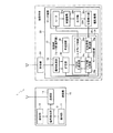
まず、図1〜4を参照しながら、本発明に係るモータ制御回路を実装するサーボ装置を備えた遠隔操作装置の構成要件について説明する。
図1に示すように、本例の遠隔操作装置1では、遠隔操作対象である被操作体(例えば、ヘリコプター、飛行機、車、船舶、ロボット等の各種模型又は産業機械)に対して送信する各種制御信号(操縦信号又は周波数設定信号)を生成する送信機10と、被操作体に搭載され、受信機20を介して受信した制御信号に基づき可動部位の動作量を制御したり、所望の駆動周波数の設定がなされるサーボ装置30とを備えて概略構成されている。
[Device configuration]
First, with reference to FIGS. 1 to 4, the configuration requirements of a remote control device including a servo device that mounts a motor control circuit according to the present invention will be described.
As shown in FIG. 1, in the
なお、受信機20には、サーボ装置30が複数接続されていてもよい。また、サーボ装置30以外にもジャイロ装置やモータコントローラー等の機器を任意に接続した構成でもよい。
Note that a plurality of
<送信機>
送信機10は、被操縦体に搭載されるサーボ装置30を操縦するための制御信号を生成して送信する装置であり、操作部11と、設定部12と、信号発生部13と、送信部14とを備えて構成される。
<Transmitter>
The
操作部11は、スティックレバー等の各種レバーやスイッチ類で構成され、各種レバーによる上下左右の操作、スイッチ類の押下操作に基づく操作量に応じたアナログ信号を、各チャンネルに対する操作信号として信号発生部13に出力する。
The
設定部12は、例えば液晶ディスプレイ等の表示装置の表示画面上に設けられたタッチパネルやエディットキー等の各種操作キーで構成され、各種設定やその設定変更を行う際に操作される。具体的には、表示装置の表示画面にサーボ装置30の駆動周波数設定画面を表示させ、これを参照しながらユーザが操作キー又はタッチパネルを所定操作することで、操縦時の操縦感覚に応じた駆動周波数の選択(本形態では、4種類の駆動周波数「駆動周波数1」〜「駆動周波数4」に対応した「設定1」〜「設定4」を選択する例とする)が行われる。そして、設定された内容に基づくディジタル信号を設定操作信号として信号発生部13に出力している。
The
信号発生部13は、操作部11からの操作信号又は設定部12からの設定操作信号を入力すると、送信部14を介してサーボ装置30に対して出力する制御信号(操縦信号又は周波数設定信号)を生成する周知の信号生成回路で構成されている。具体的には、信号発生部13は、操作部11からの操作信号をA/D変換し、時分割的に所定の周期(例えば1送信周期14〜20mSの周期で、各チャンネルのパルス幅が1520μS±600μS)で送出するような信号処理を行い、この処理により生成された制御信号を、後述する駆動機構32を所定の駆動量で駆動制御するための操縦信号(PWM信号)として送信部14に出力している。
When the operation signal from the
また、信号発生部13は、設定部12からの設定操作信号を含むシリアルデータとなるような信号処理を行い、この処理により生成された制御信号を周波数設定信号として送信部14に出力している。
In addition, the
送信部14は、信号発生部13からの制御信号(操縦信号又は周波数設定信号)を高周波変調(例えば、AM変調やFM変調)や、スペクトル拡散等で変調した後、アンテナから電波として受信機20を介してサーボ装置30に送信している。
The
<受信機>
受信機20は、アンテナから電波として受信した送信機10からの受信電波を増幅し、制御信号に復調してサーボ装置30に出力する周知の受信装置である。
<Receiver>
The
<サーボ装置>
サーボ装置30は、受信機20を介して受信した操縦信号に基づき、被操作体における可動部位(例えば、被操作体が模型飛行機であれば、ラダー、エルロン、エレベータ、エンジンスロットル等に相当)をそれぞれ独立して駆動制御するための装置であり、制御部31と、駆動機構32とを備えて構成される。
<Servo device>
Based on the control signal received via the
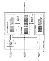
制御部31は、送信機10からの操縦信号に基づき駆動機構32を駆動制御する、所謂モータ制御回路として機能する制御用LSI(Large Scale Integration )であり、信号処理部33と、モータ制御部34と、記憶部35とを備えて各部の駆動制御を行っている。なお、制御部31を構成する各部の駆動制御は、例えば水晶発振器や分周回路で構成される周知の発振回路36からのクロック信号に同期して動作している。
The
信号処理部33は、受信機20を介して入力した制御信号のパルス幅を検出し、その検出したパルス幅情報に基づき、入力した制御信号の種類を特定して、操縦信号又は周波数設定信号を生成して一時的に保持する。そして、信号処理部33は、一時保持した操縦信号又は周波数設定信号を抽出して、後述する記憶部35の所定領域(操縦信号記憶手段35a又は周波数情報記憶手段35b)に書き込みを行っている。
The
モータ制御部34は、後述する位置検出部32dからの位置情報(駆動機構32の出力軸32cの回転位置を示す情報)に応じたパルス信号である位置信号を生成して出力する位置信号発生部34aと、記憶部35に記憶された操縦信号に応じたパルス幅(目標値)と位置信号のパルス幅(実測値)から差分データ(偏差)及びこのデータの更新タイミング(言い換えれば、差分データのサンプリング間隔)に同期したタイミング信号である差分データタイミング信号を生成して出力するパルス幅比較部34bと、比較出力である差分データを選択された駆動周波数の駆動信号となるよう信号生成して出力するPWM生成回路34cと、この駆動信号に応じた正又は逆方向の電流を流して駆動機構32の回転方向を駆動制御するドライブ回路34dとを備えている。
The
なお、パルス幅比較部34bは、位置信号の入力に際し、モータ32aの速度情報と回転方法に応じて僅かに変化させるように、速度補償が行われている。
The pulse
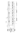
パルス幅比較部34bにおける差分データの取得方法としては、図2に示すように目標値である送信機10からの操縦信号のパルス幅から目標値を保持し、実測値である位置信号発生部34aからの位置信号のパルス幅からサンプリング毎に差分(偏差)を算出し、差分データを取得している。そして、図示のように、操縦信号である目標値が目標値A→目標値B→目標値Cと順に変化した場合は、目標値が変化した次のタイミングで各目標値に応じた差分データに適宜調整される。
As a method for acquiring the difference data in the pulse
次に、本発明の主要部であるPWM生成回路34cについて詳述する。
図3に示すように、PWM生成回路34cは、パルス生成用カウンタ34eと、カウント値範囲設定部34fと、差分データ変換部34gと、パルス生成部34hとを備えて構成され、パルス幅比較部34bからの差分データと差分データタイミング信号とに基づき、ユーザが所望する操縦感覚となるように駆動信号の駆動周波数を変換処理している。
Next, the
As shown in FIG. 3, the
パルス生成用カウンタ34eは、図4に示すようにパルス幅比較部34bからの差分データタイミング信号に同期して所定の値(18bit)までカウントアップを行い、カウント値をカウント値範囲設定部34fに出力している。
As shown in FIG. 4, the
カウント値範囲設定部34fは、記憶部35に記憶される現在選択された駆動周波数設定情報に基づき、パルス生成用カウンタ34eでカウントされたカウント値(本形態では18bitカウント)のうち、どのカウント範囲まで使用するかを設定し、その設定内容をカウント値範囲信号としてパルス生成部34hに出力している。
The count value
すなわち、カウント値範囲設定部34fは、例えばユーザが送信機10において「設定2」を選択した場合、記憶される駆動周波数設定情報のうち「駆動周波数2」が選択されるため、記憶部35に記憶された「駆動周波数2」の設定内容に基づき、カウントした18bit分のうち下位17bit分を使用することを指示するカウント値範囲信号をパルス生成部34hに出力している。
That is, for example, when the user selects “setting 2” in the
差分データ変換部34gは、記憶部35に記憶される現在選択された駆動周波数設定情報に基づき、パルス幅比較部34bから差分データタイミング信号に同期して取り込んだ差分データ(本形態では16bitのデータ)の周波数変換処理(差分データの周波数を2n 倍(n=正又は負の整数)倍する変換処理)し、その変換処理した信号を差分データ変換信号としてパルス生成部34hに出力している。
なお、差分データの周波数変換処理としては、図4(図例では何れもデューティー比50%(モータの駆動周波数1周期においてモータONの期間(すなわちモータが回転する期間)が50%である)の駆動周波数)に示すように、駆動周波数1が選択されたときの駆動周波数を「f」としたとき、駆動周波数2の周波数は「f」を2倍に変換して「2f」、駆動周波数3の周波数は「f」を4倍に変換して「4f」、駆動周波数4の周波数は「f」を8倍に変換して「8f」となるようにそれぞれ変換処理される。
The difference
Note that the frequency conversion processing of the difference data is shown in FIG. 4 (in each example, the duty ratio is 50% (the motor ON period (that is, the motor rotation period) is 50% in one cycle of the motor driving frequency). As shown in (Drive frequency), when the drive frequency when the
すなわち、差分データ変換部34gは、例えばユーザが送信機10において「設定2」を選択した場合、記憶される駆動周波数設定情報のうち「駆動周波数2」が選択されるため、記憶部35に記憶された「駆動周波数2」の設定内容に基づき、16bitで入力した差分データを21 倍(2倍)して17bit化させたデータを差分データ変換信号としてパルス生成部34hに出力している。
That is, for example, when the user selects “setting 2” in the
パルス生成部34hは、記憶部35に記憶される選択された駆動周波数設定情報と、カウント値範囲設定部34fからのカウント値範囲信号と、差分データ変換部34gからの差分データ変換信号とを基に、現在選択された駆動周波数設定情報の駆動周波数となるように駆動信号(駆動パルス)を信号生成してドライブ回路34dに出力している。
The
すなわち、パルス生成部34hは、例えばユーザが送信機10において「設定2」を選択した場合、カウント値範囲設定部34fからのカウント値範囲信号を基に、差分データ変換部34gからの差分データ変換信号のうち、下位17bit分の差分データ変換信号を実際に駆動機構32を駆動するための駆動信号(17bit周期の駆動信号)として生成し、ドライブ回路34dに出力している。
That is, for example, when the user selects “setting 2” in the
なお、モータ制御部34を1つのLSIとしてワンチップに実装したカスタムICの例であるが、当然、各部をそれぞれ独立した個々の回路として構成してもよい。
In addition, although it is an example of custom IC which mounted the
記憶部35は、EEPROM(登録商標)等の書き換え可能な不揮発性メモリで構成されている。記憶部35は、図5に示すように、操縦信号を記憶する操縦信号記憶手段35aと、実装される被操作体の仕様やユーザの操縦感覚に応じて予め設定された複数の駆動周波数設定情報と、周波数設定信号に基づく駆動周波数設定情報の選択状況を記憶する周波数情報記憶手段35bとを備え、信号処理部33からの操縦信号又は周波数設定信号をそれぞれ更新記憶している。
The
操縦信号記憶手段35aは、信号処理部33からの操縦信号を記憶する記憶領域である。操縦信号記憶手段35aは、信号処理部33から操縦信号を入力すると、パルス幅比較部34bで差分データを取得する際の目標値として更新記憶している。
The steering
周波数情報記憶手段35bは、実装される被操作体の仕様やユーザの操縦感覚に応じて予め設定された複数の駆動周波数設定情報(本形態では4つ)を各領域に分割して記憶する記憶領域である。周波数情報記憶手段35bは、図5に示すように、信号処理部33から周波数設定信号を入力すると、その信号に該当する駆動周波数情報が選択された状態(図5では、ユーザが送信機10において「設定1」を選択した場合、これに対応する「駆動周波数情報1」のフラグ「○」を立てた状態)とする。なお、信号処理部33から現在選択されている駆動周波数と異なる駆動周波数に該当する周波数設定信号を入力すると、現在選択された駆動周波数設定情報のフラグを解除して、新たに入力した周波数設定信号に該当する駆動周波数設定情報のフラグを立てた状態とする。
The frequency
ここで、駆動周波数設定情報について説明する。駆動周波数設定情報は、ユーザが所望する操縦感覚となるようにパルス幅比較部34bからの差分データを選択され駆動周波数に変換するための処理情報であり、カウント値範囲設定情報と、差分データ変換設定情報とが、所定の駆動周波数毎に関連付けした状態で記憶されている。
Here, the drive frequency setting information will be described. The drive frequency setting information is processing information for selecting the difference data from the pulse
駆動周波数設定情報毎に設定された駆動周波数は、ユーザが所望する操作感覚となるように予め実験等により得られた周波数である。本形態では、図5に示すように、所定の駆動周波数「f」を用いる場合を「駆動周波数1」とした場合、「駆動周波数2」では「f」の2倍の駆動周波数である「2f」とし、「駆動周波数3」では「f」の4倍の駆動周波数である「4f」とし、「駆動周波数4」では「f」の8倍の駆動周波数である「8f」とし、それぞれ周波数毎に別領域に記憶している。
なお、「駆動周波数1」〜「駆動周波数4」は、送信機10で選択された「設定1」〜「設定4」とそれぞれ対応している。
The driving frequency set for each piece of driving frequency setting information is a frequency obtained in advance through experiments or the like so as to obtain an operation feeling desired by the user. In the present embodiment, as shown in FIG. 5, when “predetermined drive frequency“ f ”” is used as “
Note that “driving
(カウント値範囲設定情報について)
カウント値範囲設定情報は、パルス生成用カウンタ34eでカウントされたカウント値(ビット数、本形態では「18bit」とする)のうち、現在選択された駆動周波数設定情報の駆動周波数に応じてどのカウント範囲まで差分データ変換信号を使用するかを指示するための設定情報である。
(About count value range setting information)
The count value range setting information indicates which count value (number of bits, “18 bits” in this embodiment) of the count value counted by the
本形態では、図5に示すように、パルス生成用カウンタ34eでカウントされた所定のカウント値(18bit)のうち「駆動周波数1」では「18bit分を使用する」、「駆動周波数2」では「下位17bit分を使用する」、「駆動周波数3」では「下位16bit分を使用する」、「駆動周波数4」では「下位15bit分を使用する」、としてそれぞれ設定している。
よって、カウント値範囲設定情報は、例えばユーザが送信機10において「設定1」を選択した場合、記憶される駆動周波数設定情報のうち「駆動周波数1」が選択され、パルス生成用カウンタ34eでカウントした18bit分の差分データ変換信号を駆動信号に変換処理するための設定情報として使用される。
In the present embodiment, as shown in FIG. 5, among the predetermined count values (18 bits) counted by the
Thus, for example, when the user selects “setting 1” in the
(差分データ変換設定情報について)
差分データ変換設定情報は、パルス幅比較部34bからの差分データを、現在選択された駆動周波数設定情報の駆動周波数となるようにカウント値範囲設定情報に合せて周波数変換処理(取り込んだ差分データの周波数を2n 倍(n=正又は負の整数)する変換処理)をするための設定情報である。
(About difference data conversion setting information)
The difference data conversion setting information is a frequency conversion process (of the acquired difference data) that matches the difference data from the pulse
本形態では、図5に示すように、差分データを16bitのデータとし、パルス生成用カウンタ34eでカウントされた所定のカウント値の最大が18bitとした場合、「駆動周波数1」では「22 倍(4倍)して18bit化する」、「駆動周波数2」では「21 倍(2倍)して17bit化する」、「駆動周波数3」では「20 倍(1倍)して16bitのまま使用する」、「駆動周波数4」では「2-1倍(1/2倍)して15bit化する」、としてそれぞれ設定している。
よって、差分データ変換設定情報は、例えばユーザが送信機10において「設定1」を選択した場合、記憶される駆動周波数設定情報のうち「駆動周波数1」が選択され、16bitデータとして入力した差分データを22 倍(4倍)して18bit化の差分データ変換信号に変換処理するための設定情報として使用される。
In the present embodiment, as shown in FIG. 5, when the difference data is 16-bit data and the maximum of the predetermined count value counted by the
Therefore, for example, when the user selects “setting 1” in the
駆動機構32は、ドライバ回路34dから供給される駆動信号に基づく電流量によりモータ32aが駆動し、減速機構32bを介して接続される出力軸32cの回転によって可動部位を可動する動力伝達機構である。また、出力軸32cの回転位置は位置検出部32d(例えば、ポテンショメータ、ロータリーエンコーダ、レゾルバ等の出力軸32cの位置検出(回転角度)が可能な機器であればよい)によって検出され、その位置情報が位置信号発生部34aに出力される。
The
[処理動作]
次に、本例のモータ制御回路を実装したサーボ装置30の一連の処理動作について説明する。ここでは、駆動周波数設定をした際の処理動作と、実際に被操作体を操縦した際の処理動作についてそれぞれ説明する。
[Processing operation]
Next, a series of processing operations of the
(駆動周波数数設定時の処理動作)
まず、ユーザは、送信機10を所定操作して操縦対象となる被操作体の操縦感覚に応じた駆動周波数を選択するため、操作画面上で「設定1」〜「設定4」を任意に選択する。そして、選択した駆動周波数で被操作体を駆動させるため、設定内容に応じた周波数設定信号を制御信号としてサーボ装置30に送信する。
(Processing operation when setting the number of drive frequencies)
First, the user arbitrarily selects “Setting 1” to “Setting 4” on the operation screen in order to select a driving frequency in accordance with the operation feeling of the operation target to be operated by performing a predetermined operation on the
サーボ装置30は、受信機20を介して受信した制御信号を信号処理部33に出力する。信号処理部33は、入力した制御信号のシリアルデータから周波数設定信号であると特定し、周波数設定信号を生成した後、一時的に保持する。そして、一時的に保持した周波数設定信号を記憶部35の周波数情報記憶手段35bに書き込みを行う。
The
これにより、図3に示すように周波数情報記憶手段35bに記憶される駆動周波数設定情報のうち、ユーザが送信機10で設定した駆動周波数に該当する駆動周波数設定情報が選択された状態(フラグが立った状態)となる。以降、新たな周波数設定信号が入力されるまでの間は、選択された駆動周波数設定情報に基づき、操縦信号の駆動周波数変更処理を行う。
Thereby, as shown in FIG. 3, among the drive frequency setting information stored in the frequency
(被操作体操縦時の処理動作)
まず、ユーザは、被操作体の操縦に際し、送信機10の所定操作に基づく操作信号に応じた操縦信号を制御信号としてサーボ装置30に送信する。
(Processing when manipulating the object)
First, the user transmits a control signal corresponding to an operation signal based on a predetermined operation of the
サーボ装置30は、受信機20を介して受信した制御信号を信号処理部33に出力する。信号処理部33は、入力した制御信号のパルス幅から操縦信号であると特定し、操縦信号を生成した後、一時的に保持する。そして、一時的に保持した操縦信号を記憶部35の操縦信号記憶手段35aに書き込みを行う。
The
パルス幅比較部34bは、操縦信号記憶手段35aに記憶される操縦信号のパルス幅と、駆動機構32の出力軸32cの回転位置に基づく位置情報から得られた位置信号のパルス幅から差分データを求め、PWM生成回路34cに出力する。
The pulse
PWM生成回路34cでは、まずカウント値範囲設定部34fが、現在選択されている駆動周波数設定情報におけるカウント値範囲信号を周波数情報記憶手段35bから読み出す。また、差分データ変換部34gでは、現在選択されている駆動周波数設定情報における差分データ変換設定情報を周波数情報記憶手段35bから読み出す。
In the
次に、パルス生成用カウンタ34eは、パルス幅比較部34bから差分データタイミング信号を入力すると、差分データタイミング信号に同期したサンプリング間隔tでカウントし、カウントが終了すると、それを示すカウント終了情報をカウント値範囲設定部34fに出力する。
Next, when the differential data timing signal is input from the pulse
次に、カウント値範囲設定部34fは、パルス生成用カウンタ34eからのカウント終了情報を入力すると、読み出したカウント値範囲設定情報に基づき、パルス生成用カウンタ34eでカウントされたカウント値をどのカウント範囲まで使用するかを設定し、その設定内容をカウント値範囲信号としてパルス生成部34hに出力する。さらに、差分データ変換部34gは、読み出した差分データ変換設定情報に基づき、パルス幅比較部34bから差分データタイミング信号に同期して取り込んだ差分データをカウント値範囲設定情報に合せて所定の駆動周波数となるように周波数変換処理し、その変換処理した信号を差分データ変換信号としてパルス生成部34hに出力する。
Next, when the count value
そして、パルス生成部34hによって、カウント値範囲設定部34fからのカウント値範囲設定情報と、差分データ変換部34gからの差分データ変換信号とに基づき、現在選択された駆動周波数設定情報の駆動周波数となるように駆動信号を生成し、駆動機構32に出力してモータ32aを駆動制御する。
Then, based on the count value range setting information from the count value
以上説明したように、上述したサーボ装置30は、受信機20を介して送信機10から制御信号として周波数設定信号を受信すると、予め記憶した駆動周波数設定情報のうち、受信した周波数設定信号に応じた情報を選択する。また、送信機10から制御信号である操縦信号を入力すると、パルス幅比較部34bから差分データタイミング信号に同期して取り込んだ差分データを選択された駆動周波数に対応するように周波数変換処理する。そして、パルス生成用カウンタ34eでカウントしたカウント値のうち対応するカウント範囲までの差分データ変換信号から駆動信号を生成して、ユーザが所望する操作感覚となるように駆動機構32の駆動制御を行っている。
As described above, when the
これにより、送信機10からの操縦信号をユーザの操作感覚に応じて任意に設定した駆動周波数に変換することができるため、ユーザの好みに応じたサーボ装置30を、可動部位に応じて用意することなく所望の操作感覚で操縦することができるようになる。例えば駆動周波数を高くすることで、操縦信号のパルス幅の変化量が小さい場合にも十分な回転トルクが得られるようにし、被操作体における可動部位を所定の位置まで素早く動作させることができる。また、モータ32aを駆動する最小駆動パルス幅を小さく設定できてモータ32aを滑らかに回転させることでモータ32aの回転効率を高め、さらにはモータ32aの高寿命化を図ることができるというメリットがある。
逆に、駆動周波数を低くすると、モータの回転トルクはモータに印加されるデューティー比が小さい状態となり、十分な起動トルクを得ることはできないが、被操作体を操縦するにあたり、その操縦感覚は実機に搭載した場合の操縦舵のダンパーが効いたような動きにすることができ、ユーザ個々の好みにより低速回転時のトルクを高めることできる。
Thereby, since the steering signal from the
Conversely, when the drive frequency is lowered, the rotational torque of the motor is in a state where the duty ratio applied to the motor is small, and sufficient starting torque cannot be obtained. It is possible to achieve a movement in which the damper of the steering rudder when it is mounted is effective, and it is possible to increase the torque during low-speed rotation according to the user's individual preference.
また、使用環境、被操作体の状態、天候等の変化が生じた場合であっても、その都度、PC等の各種設定機器を接続して設定する必要がなく、簡易的に、且つ柔軟に駆動性能の調整を行うことができる。 In addition, even if there is a change in the operating environment, the state of the object to be operated, the weather, etc., it is not necessary to connect and set various setting devices such as a PC each time. The drive performance can be adjusted.
ところで、上述した形態では、サーボ装置30の設定用としての設定部12、サーボ装置30の操作用としての操作部11として別構成で説明したが、例えば周波数設定の際に、設定部12における表示画面を見ながら操作部11による操作で設定内容を変更するように操作部11を設定部12の設定操作手段として利用する構成とすることもできる。
By the way, in the above-described embodiment, the setting
また、上記説明では、記憶部35に予め記憶させた駆動周波数設定情報を送信機10からの周波数設定情報によって選択したが、これに限定されることはない。例えば、図6に示すように、サーボ装置30に記憶部35に記憶した駆動周波数設定情報に対応したスイッチ機構37を具備させ、被操作体の操作前に所望の操縦感覚となる駆動周波数に該当するスイッチを切り替えることで選択する構成とすることもできる。
In the above description, the drive frequency setting information stored in advance in the
さらに、駆動周波数設定情報は、予めPC等の外部機器を介して記憶部35に記憶させることもできるが、送信機10から周波数設定信号の代わりに使用する駆動周波数に応じた駆動周波数設定情報を設定情報として送信し、サーボ装置30に設定する構成とすることもできる。
Further, the drive frequency setting information can be stored in advance in the
1…遠隔操作装置
10…送信機
11…操作部
12…設定部
13…信号発生部
14…送信部
20…受信機
30…サーボ装置
31…制御部
32…駆動機構(32a…モータ、32b…減速機構、32c…出力軸、32d…位置検出部)
33…信号処理部
34…モータ制御部(34a…位置信号発生部、34b…パルス幅比較部、34c…PWM生成回路、34d…ドライブ回路、34e…パルス生成用カウンタ部、34f…カウント値範囲設定部、34g…差分データ変換部、34h…パルス生成部)
35…記憶部(35a…操縦信号記憶手段、35b…周波数情報記憶手段)
36…発振回路
37…スイッチ機構
DESCRIPTION OF
33 ...
35 ... Storage section (35a ... Steering signal storage means, 35b ... Frequency information storage means)
36 ...
Claims (4)
前記差分データの更新タイミングを示す差分データタイミング信号に同期して、所定の値までカウントアップを行うパルス生成用カウンタと、
前記モータの駆動信号を所定の駆動周波数に変換処理するための駆動周波数設定情報のうち、現在選択された前記駆動周波数設定情報に基づき、前記パルス生成用カウンタでカウントされたカウント値のうち、どのカウント範囲まで使用するかを設定したカウント値範囲信号を出力するカウント値範囲設定部と、
現在選択された前記駆動周波数設定情報に基づく駆動周波数となるように、前記差分データタイミング信号に同期して取り込んだ前記差分データを周波数変換処理した差分データ変換信号を出力する差分データ変換部と、
前記カウント値範囲設定部からの前記カウント値範囲信号によって設定されたカウント値の範囲で、前記差分データ変換部からの前記差分データ変換信号を現在選択された前記駆動周波数設定情報の駆動周波数となる駆動信号に生成して出力するパルス生成部と、
を備えたことを特徴とするモータ制御回路。 A drive signal using difference data obtained by subtracting the pulse width of the position signal detected from the rotational position of the output shaft of the motor from the pulse width of the steering signal for controlling the motor to be controlled with a predetermined drive amount. A motor control circuit for controlling the drive of the motor,
A pulse generation counter that counts up to a predetermined value in synchronization with a differential data timing signal indicating the update timing of the differential data;
Of the drive frequency setting information for converting the drive signal of the motor to a predetermined drive frequency, which of the count values counted by the pulse generation counter is based on the currently selected drive frequency setting information A count value range setting unit that outputs a count value range signal that sets whether to use the count range,
A difference data conversion unit that outputs a difference data conversion signal obtained by frequency-converting the difference data captured in synchronization with the difference data timing signal so as to be a drive frequency based on the currently selected drive frequency setting information;
The difference data conversion signal from the difference data conversion unit becomes the drive frequency of the currently selected drive frequency setting information within the count value range set by the count value range signal from the count value range setting unit. A pulse generator that generates and outputs a drive signal;
A motor control circuit comprising:
前記カウント値範囲設定情報に合せて選択された駆動周波数となるように前記差分データを2n 倍(n=正又は負の整数)して周波数変換処理するための差分データ変換設定情報とを、所定の駆動周波数毎に関連付けした状態で記憶されていることを特徴とする請求項1記載のモータ制御回路。 The drive frequency setting information is a count value range that indicates to which count range the difference data conversion signal is used according to the selected drive frequency among the count values counted in synchronization with the difference data timing signal Configuration information and
Differential data conversion setting information for performing frequency conversion processing by multiplying the difference data by 2 n times (n = positive or negative integer) so as to be a driving frequency selected according to the count value range setting information, The motor control circuit according to claim 1, wherein the motor control circuit is stored in a state of being associated with each predetermined drive frequency.
前記制御部は、
前記操縦信号のパルス幅から前記駆動機構の出力軸の回転位置から検出した位置信号のパルス幅を差し引いて得られる差分データを、前記差分データの更新タイミングを示す差分データタイミング信号に同期して、所定の値までカウントアップを行うパルス生成用カウンタと、
前記駆動機構の駆動信号を所定の駆動周波数に変換処理するための駆動周波数設定情報のうち、現在選択された前記駆動周波数設定情報に基づき、前記パルス生成用カウンタでカウントされたカウント値のうち、どのカウント範囲まで使用するかを設定したカウント値範囲信号を出力するカウント値範囲設定部と、
現在選択された前記駆動周波数設定情報に基づく駆動周波数となるように、前記差分データタイミング信号に同期して取り込んだ前記差分データを周波数変換処理した差分データ変換信号を出力する差分データ変換部と、
前記カウント値範囲設定部からの前記カウント値範囲信号によって設定されたカウント値の範囲で、前記差分データ変換部からの前記差分データ変換信号を現在選択された前記駆動周波数設定情報の駆動周波数となる駆動信号に生成して出力するパルス生成部と、
を備えたことを特徴とするサーボ装置。 A servo device provided in a control unit that receives a control signal corresponding to a predetermined operation amount of an operation unit of a transmitter, converts the control signal into a drive signal, and drives and controls the drive mechanism,
The controller is
The difference data obtained by subtracting the pulse width of the position signal detected from the rotational position of the output shaft of the drive mechanism from the pulse width of the steering signal is synchronized with the difference data timing signal indicating the update timing of the difference data, A pulse generation counter that counts up to a predetermined value;
Of the drive frequency setting information for converting the drive signal of the drive mechanism into a predetermined drive frequency, based on the currently selected drive frequency setting information, among the count values counted by the pulse generation counter, A count value range setting unit that outputs a count value range signal in which up to which count range is used;
A difference data conversion unit that outputs a difference data conversion signal obtained by frequency-converting the difference data captured in synchronization with the difference data timing signal so as to be a drive frequency based on the currently selected drive frequency setting information;
The difference data conversion signal from the difference data conversion unit becomes the drive frequency of the currently selected drive frequency setting information within the count value range set by the count value range signal from the count value range setting unit. A pulse generator that generates and outputs a drive signal;
A servo device comprising:
前記カウント値範囲設定情報に合せて選択された駆動周波数となるように前記差分データを2n 倍(n=正又は負の整数)して周波数変換処理するための差分データ変換設定情報とを、所定の駆動周波数毎に関連付けした状態で記憶されていることを特徴とする請求項3記載のサーボ装置。 The drive frequency setting information is a count value range that indicates to which count range the difference data conversion signal is used according to the selected drive frequency among the count values counted in synchronization with the difference data timing signal Configuration information and
Differential data conversion setting information for performing frequency conversion processing by multiplying the difference data by 2 n times (n = positive or negative integer) so as to be a driving frequency selected according to the count value range setting information, 4. The servo device according to claim 3, wherein the servo device is stored in a state of being associated with each predetermined driving frequency.
Priority Applications (6)
| Application Number | Priority Date | Filing Date | Title |
|---|---|---|---|
| JP2011207559A JP5774952B2 (en) | 2011-09-22 | 2011-09-22 | MOTOR CONTROL CIRCUIT AND SERVO DEVICE MOUNTING THE CIRCUIT |
| US13/612,092 US8729849B2 (en) | 2011-09-22 | 2012-09-12 | Motor control circuit and servo device provided with the same |
| KR1020120104525A KR101341582B1 (en) | 2011-09-22 | 2012-09-20 | Motor control circuit and servo device having the same |
| CN201210356893.4A CN103023429B (en) | 2011-09-22 | 2012-09-21 | Electromotor control circuit and be provided with the servo device of this circuit |
| DE102012108951.5A DE102012108951B4 (en) | 2011-09-22 | 2012-09-21 | Motor control circuit and equipped with the same servo device |
| TW101134646A TWI450057B (en) | 2011-09-22 | 2012-09-21 | Motor control circuit and servo device mounted with same |
Applications Claiming Priority (1)
| Application Number | Priority Date | Filing Date | Title |
|---|---|---|---|
| JP2011207559A JP5774952B2 (en) | 2011-09-22 | 2011-09-22 | MOTOR CONTROL CIRCUIT AND SERVO DEVICE MOUNTING THE CIRCUIT |
Publications (3)
| Publication Number | Publication Date |
|---|---|
| JP2013066601A JP2013066601A (en) | 2013-04-18 |
| JP2013066601A5 JP2013066601A5 (en) | 2014-07-10 |
| JP5774952B2 true JP5774952B2 (en) | 2015-09-09 |
Family
ID=47828066
Family Applications (1)
| Application Number | Title | Priority Date | Filing Date |
|---|---|---|---|
| JP2011207559A Active JP5774952B2 (en) | 2011-09-22 | 2011-09-22 | MOTOR CONTROL CIRCUIT AND SERVO DEVICE MOUNTING THE CIRCUIT |
Country Status (6)
| Country | Link |
|---|---|
| US (1) | US8729849B2 (en) |
| JP (1) | JP5774952B2 (en) |
| KR (1) | KR101341582B1 (en) |
| CN (1) | CN103023429B (en) |
| DE (1) | DE102012108951B4 (en) |
| TW (1) | TWI450057B (en) |
Families Citing this family (5)
| Publication number | Priority date | Publication date | Assignee | Title |
|---|---|---|---|---|
| JP6174341B2 (en) * | 2013-03-11 | 2017-08-02 | トヨタ自動車株式会社 | Communication system, tuner, and setting method |
| JP6177590B2 (en) * | 2013-05-30 | 2017-08-09 | 三和電子機器株式会社 | Receiver for model transmission / reception system |
| TWI562530B (en) * | 2015-11-17 | 2016-12-11 | En Technologies Corp | System and way for motor-driven spreading |
| TWI621329B (en) * | 2017-07-20 | 2018-04-11 | 東元電機股份有限公司 | Motor drive control system and method thereof |
| CN109286354B (en) * | 2017-07-21 | 2020-09-15 | 东元电机股份有限公司 | Motor drive control system and method thereof |
Family Cites Families (19)
| Publication number | Priority date | Publication date | Assignee | Title |
|---|---|---|---|---|
| US5170108A (en) * | 1991-01-31 | 1992-12-08 | Daylighting, Inc. | Motion control method and apparatus for motorized window blinds and and the like |
| JP2773017B2 (en) * | 1993-04-30 | 1998-07-09 | 双葉電子工業株式会社 | Motor control device for radio control |
| US5742136A (en) * | 1994-09-20 | 1998-04-21 | Yokogawa Electric Corporation | Linear motor drive system |
| DE19526218C1 (en) * | 1995-07-18 | 1997-04-03 | Siemens Ag | Circuit device for controlling an actuator |
| JP3412730B2 (en) | 1996-01-09 | 2003-06-03 | 日本遠隔制御株式会社 | Servo motor controller |
| JPH10295950A (en) * | 1997-04-22 | 1998-11-10 | Futaba Corp | Remote control transmitting device |
| JP3573625B2 (en) * | 1998-08-10 | 2004-10-06 | 近藤科学株式会社 | Drive circuit of the model body |
| TW483232B (en) * | 2000-08-15 | 2002-04-11 | Umax Data Systems Inc | Combination system for induction motor and stepping motor, and the operating method thereof |
| JP3542032B2 (en) * | 2000-12-11 | 2004-07-14 | 株式会社ダイヘン | Servo control method and apparatus for DC motor |
| JP3948343B2 (en) * | 2002-05-10 | 2007-07-25 | 双葉電子工業株式会社 | Radio control device |
| US6897630B2 (en) * | 2002-08-16 | 2005-05-24 | Wayne-Dalton Corp. | System and related methods for sensing forces on a movable barrier |
| US7576509B2 (en) * | 2003-09-10 | 2009-08-18 | Ricoh Company, Limited | Drive control method, drive control device, belt apparatus, image forming apparatus, image reading apparatus, computer product |
| JP4716158B2 (en) * | 2004-03-24 | 2011-07-06 | 富士ゼロックス株式会社 | Motor control apparatus and image forming apparatus |
| JP4617378B2 (en) * | 2005-06-20 | 2011-01-26 | ジーメンス ヴィディーオー オートモーティヴ アクチエンゲゼルシャフト | Method and apparatus for monitoring signals |
| US8395321B2 (en) * | 2006-07-26 | 2013-03-12 | Panasonic Corporation | Vehicle headlamp control apparatus, vehicle headlamp control system and vehicle headlamp, high intensity discharge lamp control apparatus, high intensity discharge lamp control system and vehicle headlamp |
| JP2008099412A (en) * | 2006-10-11 | 2008-04-24 | Futaba Corp | Motor control device |
| WO2009040965A1 (en) * | 2007-09-27 | 2009-04-02 | Mitsubishi Electric Corporation | Controller of rotary electric machine |
| JP2009153618A (en) * | 2007-12-25 | 2009-07-16 | Futaba Corp | Motor controller for radio control |
| TW201207243A (en) * | 2010-08-06 | 2012-02-16 | Hon Hai Prec Ind Co Ltd | Method and system for controlling rotation speed of fans |
-
2011
- 2011-09-22 JP JP2011207559A patent/JP5774952B2/en active Active
-
2012
- 2012-09-12 US US13/612,092 patent/US8729849B2/en not_active Expired - Fee Related
- 2012-09-20 KR KR1020120104525A patent/KR101341582B1/en active IP Right Grant
- 2012-09-21 DE DE102012108951.5A patent/DE102012108951B4/en not_active Expired - Fee Related
- 2012-09-21 TW TW101134646A patent/TWI450057B/en active
- 2012-09-21 CN CN201210356893.4A patent/CN103023429B/en active Active
Also Published As
| Publication number | Publication date |
|---|---|
| US20130076288A1 (en) | 2013-03-28 |
| US8729849B2 (en) | 2014-05-20 |
| TW201329657A (en) | 2013-07-16 |
| CN103023429A (en) | 2013-04-03 |
| DE102012108951A1 (en) | 2013-03-28 |
| TWI450057B (en) | 2014-08-21 |
| DE102012108951B4 (en) | 2014-03-20 |
| KR20130032258A (en) | 2013-04-01 |
| KR101341582B1 (en) | 2013-12-16 |
| JP2013066601A (en) | 2013-04-18 |
| CN103023429B (en) | 2015-10-28 |
Similar Documents
| Publication | Publication Date | Title |
|---|---|---|
| JP5774952B2 (en) | MOTOR CONTROL CIRCUIT AND SERVO DEVICE MOUNTING THE CIRCUIT | |
| JP5944625B2 (en) | Auxiliary user interface for transmitter controller | |
| JPH062190B2 (en) | Radio transmitter | |
| TWI552793B (en) | Multi-function electronic device-enabled transmit controller | |
| US9165459B2 (en) | Radio control transmitter | |
| US8660710B2 (en) | Radio control transmitter, a method for transmitting steering signal in the radio control transmitter | |
| CN105700615A (en) | Airplane active side lever system | |
| US20140064040A1 (en) | Analog electronic timepiece | |
| JP2008206667A (en) | Control apparatus for wireless remote-control model and operating parameter setup system thereof | |
| JP5836655B2 (en) | Servo device and remote control device equipped with the device | |
| US10503123B2 (en) | Analog electronic timepiece and hand drive control device | |
| KR20060018244A (en) | Model traveling device, model having such traveling device, and remote-controlled toy | |
| JP6787672B2 (en) | Electronic clock, computer and hand movement control system | |
| JP2004140499A (en) | Remote control toy | |
| JPH10295950A (en) | Remote control transmitting device | |
| JP6941218B2 (en) | Electronic clocks, computers and hand movement control systems | |
| JP2010233725A (en) | Radio-control transmitter | |
| CN105771275A (en) | Toy aircraft remote control intelligent control system | |
| CN202388505U (en) | Manipulator controller with rotary knob | |
| JP2007313940A (en) | Automatic shift system for bicycle | |
| JPH0639759Y2 (en) | Radio transmitter | |
| JPH06227094A (en) | Control information memory changeable printing device | |
| JP2006054646A (en) | Channel expansion communication system | |
| JPS6124308Y2 (en) | ||
| CN106669165A (en) | Steering gear simulation operation debugger |
Legal Events
| Date | Code | Title | Description |
|---|---|---|---|
| A521 | Request for written amendment filed |
Free format text: JAPANESE INTERMEDIATE CODE: A523 Effective date: 20140527 |
|
| A621 | Written request for application examination |
Free format text: JAPANESE INTERMEDIATE CODE: A621 Effective date: 20140527 |
|
| A977 | Report on retrieval |
Free format text: JAPANESE INTERMEDIATE CODE: A971007 Effective date: 20150526 |
|
| TRDD | Decision of grant or rejection written | ||
| A01 | Written decision to grant a patent or to grant a registration (utility model) |
Free format text: JAPANESE INTERMEDIATE CODE: A01 Effective date: 20150602 |
|
| A61 | First payment of annual fees (during grant procedure) |
Free format text: JAPANESE INTERMEDIATE CODE: A61 Effective date: 20150702 |
|
| R150 | Certificate of patent or registration of utility model |
Ref document number: 5774952 Country of ref document: JP Free format text: JAPANESE INTERMEDIATE CODE: R150 |
|
| R250 | Receipt of annual fees |
Free format text: JAPANESE INTERMEDIATE CODE: R250 |
|
| R250 | Receipt of annual fees |
Free format text: JAPANESE INTERMEDIATE CODE: R250 |
|
| R250 | Receipt of annual fees |
Free format text: JAPANESE INTERMEDIATE CODE: R250 |
|
| R250 | Receipt of annual fees |
Free format text: JAPANESE INTERMEDIATE CODE: R250 |
|
| R250 | Receipt of annual fees |
Free format text: JAPANESE INTERMEDIATE CODE: R250 |
|
| R250 | Receipt of annual fees |
Free format text: JAPANESE INTERMEDIATE CODE: R250 |