JP5774836B2 - Digital price indicator and ESL system including the same - Google Patents
Digital price indicator and ESL system including the same Download PDFInfo
- Publication number
- JP5774836B2 JP5774836B2 JP2010242017A JP2010242017A JP5774836B2 JP 5774836 B2 JP5774836 B2 JP 5774836B2 JP 2010242017 A JP2010242017 A JP 2010242017A JP 2010242017 A JP2010242017 A JP 2010242017A JP 5774836 B2 JP5774836 B2 JP 5774836B2
- Authority
- JP
- Japan
- Prior art keywords
- display
- price indicator
- digital price
- container
- digital
- Prior art date
- Legal status (The legal status is an assumption and is not a legal conclusion. Google has not performed a legal analysis and makes no representation as to the accuracy of the status listed.)
- Expired - Fee Related
Links
Images


Classifications
-
- G—PHYSICS
- G09—EDUCATION; CRYPTOGRAPHY; DISPLAY; ADVERTISING; SEALS
- G09F—DISPLAYING; ADVERTISING; SIGNS; LABELS OR NAME-PLATES; SEALS
- G09F3/00—Labels, tag tickets, or similar identification or indication means; Seals; Postage or like stamps
- G09F3/08—Fastening or securing by means not forming part of the material of the label itself
- G09F3/18—Casings, frames or enclosures for labels
- G09F3/20—Casings, frames or enclosures for labels for adjustable, removable, or interchangeable labels
- G09F3/204—Casings, frames or enclosures for labels for adjustable, removable, or interchangeable labels specially adapted to be attached to a shelf or the like
-
- G—PHYSICS
- G06—COMPUTING; CALCULATING OR COUNTING
- G06Q—INFORMATION AND COMMUNICATION TECHNOLOGY [ICT] SPECIALLY ADAPTED FOR ADMINISTRATIVE, COMMERCIAL, FINANCIAL, MANAGERIAL OR SUPERVISORY PURPOSES; SYSTEMS OR METHODS SPECIALLY ADAPTED FOR ADMINISTRATIVE, COMMERCIAL, FINANCIAL, MANAGERIAL OR SUPERVISORY PURPOSES, NOT OTHERWISE PROVIDED FOR
- G06Q30/00—Commerce
- G06Q30/06—Buying, selling or leasing transactions
-
- G—PHYSICS
- G09—EDUCATION; CRYPTOGRAPHY; DISPLAY; ADVERTISING; SEALS
- G09F—DISPLAYING; ADVERTISING; SIGNS; LABELS OR NAME-PLATES; SEALS
- G09F3/00—Labels, tag tickets, or similar identification or indication means; Seals; Postage or like stamps
- G09F3/08—Fastening or securing by means not forming part of the material of the label itself
- G09F3/16—Fastening or securing by means not forming part of the material of the label itself by clamps
-
- G—PHYSICS
- G09—EDUCATION; CRYPTOGRAPHY; DISPLAY; ADVERTISING; SEALS
- G09F—DISPLAYING; ADVERTISING; SIGNS; LABELS OR NAME-PLATES; SEALS
- G09F3/00—Labels, tag tickets, or similar identification or indication means; Seals; Postage or like stamps
- G09F3/08—Fastening or securing by means not forming part of the material of the label itself
- G09F3/18—Casings, frames or enclosures for labels
- G09F3/20—Casings, frames or enclosures for labels for adjustable, removable, or interchangeable labels
- G09F3/208—Electronic labels, Labels integrating electronic displays
-
- G—PHYSICS
- G09—EDUCATION; CRYPTOGRAPHY; DISPLAY; ADVERTISING; SEALS
- G09F—DISPLAYING; ADVERTISING; SIGNS; LABELS OR NAME-PLATES; SEALS
- G09F9/00—Indicating arrangements for variable information in which the information is built-up on a support by selection or combination of individual elements
- G09F9/30—Indicating arrangements for variable information in which the information is built-up on a support by selection or combination of individual elements in which the desired character or characters are formed by combining individual elements
- G09F9/35—Indicating arrangements for variable information in which the information is built-up on a support by selection or combination of individual elements in which the desired character or characters are formed by combining individual elements being liquid crystals
Description
本発明は、デジタル価格表示器に係り、より詳細には、実時間で価格及び製品の仕様などを表示するとともに、商品情報を便利に入力することができるデジタル価格表示器及びそれを含むESL(Electronic Shelf Label)システムに関するものである。 The present invention relates to a digital price indicator, and more particularly, displays a price and product specifications in real time, and a digital price indicator capable of conveniently inputting product information and an ESL ( Electronic Shelf Label) system.
近年、デパートまたは大型スーパーのような商店では、流通及び物流産業の発展に伴って多くの製品を陳列棚に陳列し、該陳列棚には、陳列される製品の価格及び情報などを表示するための価格表示具が装着される。 In recent years, stores such as department stores or large supermarkets display many products on display shelves with the development of the distribution and logistics industries, and the display shelves display prices and information of products to be displayed. The price indicator is installed.
この価格表示具は、陳列棚にプレートを固定し、該プレートに、製品の単価、産地、特徴、広報文句などを記載可能な表示領域が設けられた表示パネルが着脱可能に装着される。 In this price indicator, a plate is fixed to a display shelf, and a display panel provided with a display area in which a unit price of a product, a place of production, a feature, a publicity phrase and the like can be described is detachably mounted on the plate.
しかし、従来の価格表示具は、通常、プレートの位置が固定されており、売り場の管理者は、表示パネルの位置を必要によって変更し難いという問題点がある。 However, the conventional price indicator usually has a problem that the position of the plate is fixed and it is difficult for the manager of the sales floor to change the position of the display panel if necessary.
そして、従来の価格表示具は、表示パネルが着脱可能な構造とされているので、売り場を訪ねた顧客が不注意でまたは誤って表示パネルをプレートから落として紛失する恐れもある。 Since the conventional price indicator has a structure in which the display panel can be attached and detached, a customer who visits the sales floor may inadvertently or accidentally drop the display panel from the plate and lose it.
また、従来の価格表示具は、陳列される製品ごとにプレートに装着される表示パネルを別々に製作し、様々な形態、色及び文字を表現できるが、該当の品物が価格変動や売り切れなどによりそれ以上販売されない場合には、表示パネルを廃棄しなければならず、材料の浪費が多かった。 In addition, the conventional price indicator can produce display panels to be mounted on the plate separately for each product to be displayed, and can express various forms, colors, and letters. If it was not sold any more, the display panel had to be discarded, which was a waste of material.
一方、大型スーパーには、陳列商品に関する情報及びその価格を表示する価格表示板が使用される。 On the other hand, for large supermarkets, price display boards for displaying information on displayed products and their prices are used.
既存の価格表示板は、使用者が手作業でいちいち商品名及び価格を記載したり、商品名及び価格の記載されたボードをはさむ方式で、商品情報を入力した。このような手作業による商品情報入力方法は非常に面倒であり、商品情報入力作業の効率性が低下する。 For the existing price display board, the user inputs the product information by manually entering the product name and price one by one or by sandwiching the board on which the product name and price are written. Such a manual product information input method is very troublesome, and the efficiency of the product information input operation is reduced.
このような既存の商品情報入力方法の面倒さを解消する目的で、電子的ディスプレイ装置を用いたデジタル価格表示器が登場した。デジタル価格表示器は、所望の情報を表示できるLCDなどのディスプレイ装置に、陳列商品に関する情報及びその価格を表示する。 In order to eliminate the troublesomeness of the existing product information input method, a digital price indicator using an electronic display device has appeared. The digital price indicator displays information about the displayed product and its price on a display device such as an LCD that can display desired information.
このデジタル価格表示器は、筆記ツールによる手書きやボードなどをはめる機械的作業ではなく、表示しようとする情報をキーボードなどを介して入力することによって、商品情報入力作業の効率性を高めることができる。 This digital price indicator can improve the efficiency of product information input work by inputting information to be displayed through a keyboard, etc., rather than mechanical work to put handwriting or a board with a writing tool. .
しかし、このデジタル価格表示器においても、使用者が情報を直接入力しなければならず、面倒だった。 However, even in this digital price indicator, the user has to input information directly, which is troublesome.
本発明は上記問題点を改善するために案出されたもので、その目的は、売り場の管理者にとっては、容易に製品の在庫及び販売現況を把握できるとともに、製品の陳列される陳列棚に着脱自在に容易に結合させることができるが、顧客は陳列棚から分離し難い、デジタル価格表示器を提供することにある。 The present invention has been devised in order to improve the above-mentioned problems. The purpose of the present invention is to make it easy for sales floor managers to grasp the stock and sales status of products and to display shelves on which products are displayed. The customer is to provide a digital price indicator that can be easily detachably coupled but is difficult to separate from the display shelf.
本発明の他の目的は、使用者が商品情報を直接入力する面倒さを解消し、效率的に商品情報入力作業を行うことができるデジタル価格表示器を提供することにある。 Another object of the present invention is to provide a digital price indicator that eliminates the troublesome direct input of product information by a user and can efficiently perform product information input operations.
本発明のさらに他の目的は、商品情報を便利に入力できるデジタル価格表示器を含むESL(Electronic Shelf Label)システムを提供することにある。 Still another object of the present invention is to provide an ESL (Electronic Shelf Label) system including a digital price indicator that allows convenient input of merchandise information.
上記の目的を達成するために、本発明の第1実施例によるデジタル価格表示器は、
製品の陳列される陳列棚に装着されて、電源を供給する電源供給部と、
前記陳列棚に着脱可能に結合されて、前記電源供給部から供給される電源で充電し、陳列棚に陳列される製品の価格、仕様及び広報イメージを出力する表示本体と、
前記陳列棚に設けられて、前記表示本体が固定されるとその表示本体が前記電源供給部と電気的に連結されるように、一側には陽極が形成され、他側には陰極が形成される収容具と、
前記表示本体に設けられ、前記収容具にスライディング結合して前記陽極及び陰極と電気的に連結され、前記収容具から分離されることを制限する結合具と、
を含む。
In order to achieve the above object, a digital price indicator according to a first embodiment of the present invention includes:
A power supply unit that is mounted on a display shelf on which products are displayed and supplies power;
A display main body that is detachably coupled to the display shelf, is charged by a power source supplied from the power supply unit, and outputs a price, a specification, and a publicity image of a product displayed on the display shelf;
An anode is formed on one side and a cathode is formed on the other side so that when the display body is fixed on the display shelf, the display body is electrically connected to the power supply unit. With a storage device,
A coupling provided on the display body, slidingly coupled to the container and electrically connected to the anode and the cathode, and restricting separation from the container;
including.
また、本発明の第2実施例によるデジタル価格表示器は、
商品のバーコードをスキャンして認識するバーコードスキャナーと、
商品に関する情報を記憶するメモリーと、
前記メモリーに記憶された商品に関する情報を表示するディスプレイ装置と、
ESL(Electronic Shelf Label)サーバーと通信を行う通信モジュールと、
前記バーコードスキャナーが認識した商品のバーコード情報を、前記通信モジュールを通じて前記ESLサーバーに伝送し、前記ESLサーバーから前記商品に関する情報を受信して前記メモリーに記憶させる制御部と、
を含む。
The digital price indicator according to the second embodiment of the present invention is:
A barcode scanner that scans and recognizes product barcodes;
A memory to store information about the product,
A display device for displaying information about the product stored in the memory;
A communication module that communicates with an ESL (Electronic Shelf Label) server;
A controller that transmits the barcode information of the product recognized by the barcode scanner to the ESL server through the communication module, receives information about the product from the ESL server, and stores the information in the memory;
including.
また、本発明の第3実施例によるデジタル価格表示器は、
商品に付着されたRFタグを読み取るRFIDリーダと、
商品に関する情報を表示するディスプレイ装置と、
ESLサーバーと通信を行う通信モジュールと、
前記RFIDリーダが読み取ったタグ情報を、前記通信モジュールを通じて前記ESLサーバーに伝送し、前記ESLサーバーから前記タグに関する商品情報を受信して前記ディスプレイ装置に表示する制御部と、
を含む。
The digital price indicator according to the third embodiment of the present invention is:
An RFID reader that reads an RF tag attached to a product;
A display device for displaying information about the product;
A communication module for communicating with the ESL server;
Tag information read by the RFID reader is transmitted to the ESL server through the communication module, receives product information about the tag from the ESL server, and displays it on the display device;
including.
また、上記の目的を達成するために、本発明によるデジタル価格表示器を含むESLシステムは、
商品に付着されたタグに記録された情報を読み取って伝送するデジタル価格表示器と、
前記デジタル価格表示器から伝送された情報を受信して、対応する情報を前記デジタル価格表示器に伝送するESLサーバーと、を含むESLシステムであって、
前記デジタル価格表示器は、
商品に付着されたタグに記録された情報を読み取るタグ読み取りモジュールと、
商品に関する情報を表示するディスプレイ装置と、
前記ESLサーバーと通信を行う第1通信モジュールと、
前記タグ読み取りモジュールにより読み取られた前記タグの情報を、前記第1通信モジュールを通じて前記ESLサーバーに伝送し、前記ESLサーバーから前記タグに関する商品情報を受信して前記ディスプレイ装置に表示する第1制御部と、を含み、
前記ESLサーバーは、
前記デジタル価格表示器と通信を行う第2通信モジュールと、
商品に関する情報を記憶するメモリーと、
前記デジタル価格表示器から前記タグの情報を前記第2通信モジュールを通じて受信すると、前記タグに関する商品情報を前記メモリーから検索して前記デジタル価格表示器に伝送する第2制御部と、を含む。
In order to achieve the above object, an ESL system including a digital price indicator according to the present invention includes:
A digital price indicator that reads and transmits the information recorded on the tag attached to the product;
An ESL server that receives information transmitted from the digital price indicator and transmits corresponding information to the digital price indicator;
The digital price indicator
A tag reading module that reads information recorded on a tag attached to the product;
A display device for displaying information about the product;
A first communication module for communicating with the ESL server;
A first control unit that transmits information on the tag read by the tag reading module to the ESL server through the first communication module, receives product information about the tag from the ESL server, and displays the product information on the display device. And including
The ESL server is
A second communication module for communicating with the digital price indicator;
A memory to store information about the product,
And a second controller that retrieves product information related to the tag from the memory and transmits the information to the digital price indicator when the tag information is received from the digital price indicator through the second communication module.
以下、添付の図面を参照しつつ、本発明の好適な実施例について説明する。図面において、構成要素の大きさや形状などは、説明の明瞭性と便宜のために誇張して示すことができ、本発明の構成及び作用を考慮して特別に定義された用語は、使用者、運用者の意図または慣例によって可変し、よって、それらの用語に対する定義は、本明細書全般にわたる内容に基づいてなされるべきである。 Hereinafter, preferred embodiments of the present invention will be described with reference to the accompanying drawings. In the drawings, the size and shape of components can be exaggerated for the sake of clarity and convenience, and terms specifically defined in view of the configuration and operation of the present invention are the user, It varies according to the operator's intention or practice, and therefore the definitions for these terms should be made based on the contents throughout this specification.
図1は、本発明の一実施例によるデジタル価格表示器の結合関係を示す概念図であり、図2は、本発明の主要部である表示本体の一実施例を示す概念図であり、図3及び図4は、本発明の主要部である収容具の様々な実施例を示す概念図であり、図5及び図6は、本発明の主要部である結合具の様々な実施例を示す概念図である。 FIG. 1 is a conceptual diagram showing a coupling relationship of a digital price indicator according to an embodiment of the present invention, and FIG. 2 is a conceptual diagram showing an embodiment of a display body which is a main part of the present invention. 3 and 4 are conceptual diagrams showing various embodiments of the container that is the main part of the present invention, and FIGS. 5 and 6 show various examples of the coupler that is the main part of the present invention. It is a conceptual diagram.
本発明のデジタル価格表示器は、陳列棚700に固定される表示本体300と、フェンス800に設けられた収容具400と、表示本体300に設けられた結合具500と、を含む。
The digital price indicator of the present invention includes a display
電源供給部900は、製品の陳列される陳列棚700の一側に装着されて、後述する表示本体300に電源を供給する。
The
表示本体300は、陳列棚700に着脱可能に結合されて、電源供給部900から供給される電源で充電しながら、陳列棚700に陳列される製品の価格、仕様及び広報イメージを表示するもので、後述する結合具500が設けられる空間を提供する。
The display
収容具400は、陳列棚700の長さ方向に沿って、一側には陽極401が形成され、他側には陰極402が形成され、表示本体300が収容具400固定されながら電源供給部900と電気的に連結される。
The
収容具400は、既存の陳列棚や組立式アングル等を含む既存の設備に形成されるものとすることができる。
The
結合具500は、表示本体300に設けられ、収容具400にスライディング結合すると陽極401及び陰極402と電気的に連結され、表示本体300が収容具400から分離されることを制限する。
The
すなわち、結合具500は、収容具400への結合は容易であるが、収容具400から分離するためには別の分離用ツールを使用しなければならない構造となっている。
In other words, the
本発明は、上記の構成によって適用及び実施が可能であり、他の実施例の説明のために、以下、主要構成要素別に説明する。 The present invention can be applied and implemented by the above-described configuration, and will be described below according to main components for the description of other embodiments.
まず、陳列棚700には、結合具500が前記に結合されることで、表示本体300を固定するフェンス800が設けられ、収容具400は、フェンス800の長さ方向に沿って形成される。
First, the
フェンス800は、製品(図示せず)の陳列される陳列棚700の縁に沿って設置されて、陳列される製品が陳列棚700から落下することを防ぎながら、収容具400の設けられる空間及び表示本体300の装着される空間を提供する。
The
電源供給部900は、上記のように、表示本体300に電源を供給するもので、蓄電池910及び過負荷回路920を含む。
As described above, the
蓄電池910は、収容具400の両側にそれぞれ設置された陽極401及び陰極402と外部電力線901とを電気的に連結する。
The
過負荷回路920は、外部電力線901と蓄電池910との間に設置されて、過負荷による蓄電池910の損傷を防止する役割を果たす。
The
ここで、過負荷回路920と外部電力線901との間には、外部電力線901から供給される交流を直流に変換するDCアダプター930がさらに設けられる。
Here, a
したがって、電源供給部900は、外部電力線901と連結された状態では持続して表示本体300に電源供給をしながら、同時に蓄電池910に表示本体300の駆動電源を蓄積する。
Accordingly, the
また、電源供給部900は、停電や外部電力線901の欠陥などで電源供給が遮断されると、蓄積された駆動電源が消耗されるまで、フェンス800に装着された表示本体300に電源を供給する。
In addition, when the power supply is interrupted due to a power failure or a defect in the
表示本体300は、陳列棚700に陳列される製品の価格、仕様及び広報イメージを、サーバー(図示せず)から有線または無線ネットワークを通じて受信する。
The display
表示本体300は、サーバーと有線または無線ネットワークで連結されて、該当の製品の在庫及び探したい製品の位置を把握し易くなるように、小型の画像カメラや感知センサーなどをさらに含むこともできる。
The display
そのために、表示本体300は、図2に示すように、ボディー310と、ディスプレイモジュール320と、通信モジュール330と、マイクロプロセッサユニット(Micro Processor Unit:以下、「MPU」という。)340と、充電池350と、を含む。
Therefore, as shown in FIG. 2, the display
未説明符号301は、操作ボタンを表す。
An
ボディー310は、フェンス800に固定されるもので、後述するディスプレイモジュール320、通信モジュール330、MPU340及び充電池350などを内蔵する空間を有する。
The
ディスプレイモジュール320は、ボディー310に内蔵されて、陳列棚700に陳列される製品の価格、仕様及び広報イメージを切り替えつつ出力する画面を提供する。
The
通信モジュール330は、ボディー310に内蔵されて、サーバーから、有線または無線ネットワーク通信を通じて、陳列棚700に陳列される製品の価格、仕様及び広報イメージに関する情報などを受信してディスプレイモジュール320に伝達する。
The
MPU 340は、ボディー310に内蔵されて、ディスプレイモジュール320の画面出力及び通信モジュール330の通信を制御し、該画面出力プロセス及び通信プロセスで処理される情報量の送受信による一連の計算を行う。
The
充電池350は、ボディー310に内蔵されて、ボディー310がフェンス800に固定されると電源供給部900と電気的に連結されながらディスプレイモジュール320、通信モジュール330及びMPU340の駆動のための電源を供給する。
The
収容具400は、フェンス800の長さ方向に沿って形成されたスリット状のレール410の形態にすることもでき、フェンス800の長さ方向に沿って穿設された複数の孔420の形態にすることもできる。この場合、レール410に図5のように対応する形態、または孔420に図6のように対応する形態の後述する結合具500を結合することができる。
The
ここで、レール410では、フェンス800の長さ方向に沿って、一側に陽極401が設けられ、他側に陰極402が設けられ、孔420では、一周縁部に陽極401が設けられ、他周縁部に陰極402が設けられる。
Here, in the
この場合、フェンス800は、陽極401及び陰極402が後述の結合具500と結合する部位を除いては、使用者の不注意により感電事故が起きないように、全体的に絶縁処理をする。
In this case, the
結合具500は、収容具400への結合は容易であるが、収容具400、すなわち、フェンス800からの分離は、別のツール無しでは、し難い構造を有するもので、第1片部510、第2片部520及び第1フック530を含む。
The
第1片部510は、収容具400、すなわち、レール410または孔420に収容されるピン状のもので、結合具500の重心を取る骨組の役割を果たす。
The
第2片部520は、収容具400の幅lに対応するように第1片部510の両側に離隔形成されて弾性変形及び弾性復元を許容するもので、第2片部520のそれぞれの外側から第1片部510側に向かう全体距離l'は、収容具400の幅lと同一である。
The
第1フック530は、第2片部520の先端部に設けられ、先端に行くほど第1片部510側に向かって次第に狭まる傾斜面を形成し、この傾斜面が収容具400にスライディングして引っ掛かることで表示本体300の分離を制限する。
The
ここで、第2片部520の基端部には、陽極401及び陰極402と接触する電極端子521が設けられ、したがって、結合具500が収容具400に挿着すると電源供給部900に電気的に連結される。
Here, an
一方、本発明のデジタル価格表示器は、図7及び図8に示すような実施例を適用することもできる。 On the other hand, the embodiment as shown in FIGS. 7 and 8 can be applied to the digital price display of the present invention.
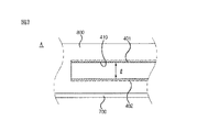
図7は、本発明の他の実施例によるデジタル価格表示器の結合関係を示す分解斜視図であり、図8は、本発明の他の実施例によるデジタル価格表示器の結合関係を示す背面概念図である。 FIG. 7 is an exploded perspective view showing a connection relationship of a digital price indicator according to another embodiment of the present invention, and FIG. 8 is a rear view showing a connection relationship of a digital price indicator according to another embodiment of the present invention. FIG.
図7及び図8を参照すると、他の実施例による本発明のデジタル価格表示器は、陳列棚700に設けられたフェンス800と、フェンス800に固定される表示本体300と、フェンス800に設けられた収容具400と、表示本体300に設けられた結合具500と、収容具400と結合具500とを固定させる固定具600と、を含む。
7 and 8, a digital price indicator according to another embodiment of the present invention is provided on a
フェンス800、表示本体300及び収容具400は、上記の一実施例のデジタル価格表示器と略同様に構成されるので、便宜上、その詳細は省略する。
Since the
参考として、図7及び図8に表示されていない図面符号は、図1乃至図6のそれを参照すれば良く、図7及び図8では、収容具400は孔420とし、結合具500は突起550とする。
For reference, the reference numerals not shown in FIGS. 7 and 8 may refer to those in FIGS. 1 to 6. In FIGS. 7 and 8, the
また、図7乃至図10では、図面の理解を助けるために、便宜上、陽極401、陰極402及び電極端子521は省略しており、陽極401及び陰極402と電極端子521との具体的な結合関係は、図1乃至図6を参照されたい。
7 to 10, for the sake of convenience, the
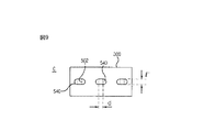
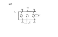
結合具500、すなわち、突起550は、表示本体300に設けられて、収容具400、すなわち、孔420に収容されるもので、図9に示すような突条540、または図10に示すような突起550とすることができる。
The
突条540は、図3に示すようなレール410に対応して表示本体300から少なくとも一つが突設され、レール410の形成方向と直交する方向にスリット502が貫通形成される。
At least one
突起550は、孔420に対応して表示本体300から少なくとも一つが突設され、フェンス800の長さ方向と直交する方向にスリット502が貫通形成される。
At least one
スリット502には、後述する固定具600が係合する。
A fixing tool 600 described later is engaged with the
ここで、突条540と突起550の幅l"は、収容具400の幅lに対応する。
Here, the width l ″ of the
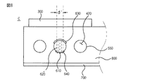
固定具600は、結合具500にスライディング結合し、結合具500から分離されることを制限し、両端がフェンス800に固定されるもので、前記収容具400と前記結合具500が締結された状態で結合され、第3片部610、第4片部620、固定片部630、及び第2フック640を含む。
The fixture 600 is slidingly coupled to the
第3片部610は、スリット502より長いまたは等しい長さで製作され、スリット502への挿入において重心を取る骨組の役割を果たす。
The
第4片部620は、スリット502の幅dに対応するように第3片部610の両側に一定の距離d'で離隔形成され、弾性変形及び弾性復元しつつスリット502に挿固定される。ここで、幅dと距離d'は同一である。
The
固定片部630は、第3片部610の一端及び第4片部620の一端に結合され、スリット502の一側に引っ掛かりながら固定される。
The fixed
第2フック640は、第4片部620の他端に設けられ、先端に行くほど第3片部610側に向かって次第に狭まる傾斜面とされ、スリット502にスライディングして結合しつつ第4片部620の弾性変形及び弾性復元を許容し、最終的には結合具500からの分離を制限する。
The
以上のように、本発明は、売り場の管理者にとっては、容易に製品の在庫及び販売現況を把握できるとともに、製品の陳列される陳列棚に着脱自在に結合させることができ、顧客は陳列棚から分離し難いデジタル価格表示器を提供することを基本的な技術思想としている。 As described above, the present invention makes it easy for the manager of the sales floor to grasp the stock and the current sales status of the product, and can be detachably coupled to the display shelf on which the product is displayed. The basic technical philosophy is to provide a digital price indicator that is difficult to separate.
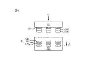
一方、図11は、本発明の一実施例によるESLシステムの概略的な構成を示す図である。 On the other hand, FIG. 11 is a diagram showing a schematic configuration of an ESL system according to an embodiment of the present invention.
図11を参照すると、ESLシステムは、商品管理のためのデータを記憶し分配するESLサーバー200と、ESLサーバー200から商品情報を受信してディスプレイ装置に表示するデジタル価格表示器100と、を含む。
Referring to FIG. 11, the ESL system includes an
デジタル価格表示器100は、商品の陳列された陳列棚において購買者が見やすい位置に装着され、その近辺に陳列された商品に関する情報(例:商品名及び価格)を表示する。
The
ESLサーバー200とデジタル価格表示器100とは、中継器500を介して通信チャンネルを形成することができる。ESLサーバー200と中継器500とは、イーサーネットなどの有線ネットワークまたはワイファイ(WiFi(登録商標))などの無線ネックワークで連結することができる。中継器500とデジタル価格表示器100とは、ワイファイ、ブルートゥス等の無線ネックワークで連結することができる。
The
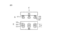
図12は、本発明の他の実施例によるデジタル価格表示器を示す図である。 FIG. 12 illustrates a digital price indicator according to another embodiment of the present invention.
図12を参照すると、デジタル価格表示器101は、商品タグ読み取りモジュールで、商品に付着されたタグのバーコードをスキャンして認識するバーコードスキャナー111と、商品に関する情報を記憶するメモリー121と、メモリー121に記憶された商品に関する情報を表示するディスプレイ装置141と、ESLサーバー200(図11参照)と通信を行う通信モジュール161と、バーコードスキャナー111で認識した商品のバーコード情報を、通信モジュール161を通じてESLサーバー200に伝送し、ESLサーバー200から当該商品に関する情報を受信してメモリー121に記憶させる制御部181と、を含む。一方、デジタル価格表示器101が商品情報を入力するように指示する管理者の指令を受け付ける操作部191をさらに含むことができる。
Referring to FIG. 12, the
ディスプレイ装置141は、LCD、PDP、LED、CRTなどを含む装置とすることができる。
The
バーコードスキャナー111は、様々な形態に具現することができる。一例として、ディスプレイ装置141が設置された面の上部に位置している商品のバーコードをスキャンしうるように設置することができる。これは、主に、価格表示器の価格表示面が、使用者の見やすい方に向かっており、商品のバーコードを認識する時にも、この価格表示面に商品を当て易いことを勘案したものである。
The
他の例として、バーコードスキャナー111は、デジタル価格表示器101の本体を独立して構成し、この本体にコイル状の導線で連結された形態とすることもできる。
As another example, the
図11で、ESLサーバー200の通信モジュールは、別途の中継器500を介してデジタル価格表示器101(図11では、参照番号100を付してデジタル価格表示器を代表的に示している。)と通信を行う。中継器500がブルートゥス(Bluetooth(登録商標))、ジグビー(Zigbee(登録商標))等の近距離無線通信を支援する場合、デジタル価格表示器101の通信モジュール161は、近距離通信モジュールとすれば良い。
In FIG. 11, the communication module of the
または、ESLサーバー200とデジタル価格表示器101とがイーサーネット等の有線ネットワークで直接連結された場合、デジタル価格表示器101の通信モジュール161は、有線ネットワーク用ランカードとすれば良い。
Alternatively, when the
操作部191は、デジタル価格表示器101が商品情報入力作業を行うように売り場の管理者が指示する旨を受け付けるものである。操作部191のキーパッドは、入力用ユーザインターフェース装置とすることができる。
The
制御部181は、デジタル価格表示器101の全体構成要素の動作を制御することができる。制御部181は、操作部191で商品情報入力指示を受け付けると、図13に示すような商品情報表示方法を行うことができる。
The
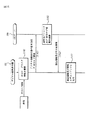
図13に示す商品情報表示方法は、デジタル価格表示器100のバーコードスキャナーが商品のバーコードを認識する段階(S130)と、デジタル価格表示器100からESLサーバー200に、認識したバーコード情報を伝送する段階(S140)と、ESLサーバー200が当該バーコード情報を受信し、デジタル価格表示器100及び商品を登録する段階(S150)と、ESLサーバー200から登録されたデジタル価格表示器100に、登録された商品に関する情報を伝送する段階(S160)と、デジタル価格表示器100に伝送された商品情報をディスプレイする段階(S170)と、を含む。
In the product information display method shown in FIG. 13, the barcode scanner of the
上記S130段階では、従来のバーコード認識端末機を用いた商品バーコード入力過程と略同様の過程が行われる。売り場の管理者が、デジタル価格表示器100の近傍の陳列領域に陳列されている(または陳列される)商品を取って、この商品に付着されたバーコードをデジタル価格表示器100のバーコードスキャナーにスキャンすると、上記S130段階が行われる。
In step S130, substantially the same process as a product barcode input process using a conventional barcode recognition terminal is performed. The manager of the sales floor takes a product displayed (or displayed) in a display area in the vicinity of the
上記S140段階では、無線通信ネットワークを用いてデジタル価格表示器100からESLサーバー200に、認識した商品のバーコード情報及びデジタル価格表示器100の識別情報(例:ID)を伝送することができる。
In step S140, the barcode information of the recognized product and the identification information (eg, ID) of the
上記S150段階で、ESLサーバー200は、内部データベースにデジタル価格表示器100の識別情報(例:ID)及び該デジタル価格表示器100に表示する商品を記録することができる。
In step S150, the
上記S160段階では、各登録されたデジタル価格表示器100ごとに、該当のデジタル価格表示器100に表示する商品に関する情報(例:商品名及び価格)を伝送することができる。
In step S <b> 160, for each registered
上記S170段階で、デジタル価格表示器100は、上記S160段階で伝送された商品に関する情報を、内部メモリーに記憶し、ディスプレイ装置に、その近傍の陳列領域に陳列された(または陳列される)商品に関する情報(例:商品名及び価格)を表示することができる。
In step S170, the
デジタル価格表示器100を操作する売り場の管理者は、下記のような過程に従って商品情報をデジタル価格表示器100に表示することができる。
The manager of the sales floor who operates the
多数個のデジタル価格表示器100が装着された陳列棚に対して、陳列棚に陳列された商品を管理する使用者は、各デジタル価格表示器100のバーコードスキャナー111に、近傍の陳列領域に陳列された(または陳列される)商品をスキャンする。
For a display shelf with a large number of
これにより、デジタル価格表示器100では、上記S130段階及びS140段階が行われる。
As a result, the
続いて、ESLサーバー200で上記S150段階乃至S160段階が行われ、デジタル価格表示器100でS170段階が行われることで、デジタル価格表示器100には、その近傍の陳列領域に陳列された商品の商品名及び価格が表示される。
Subsequently, the steps S150 to S160 are performed in the
以上の商品情報表示方法によると、使用者が商品情報を直接入力する面倒さを解消し、效率的に商品情報を入力する作業を行うことができる。 According to the merchandise information display method described above, it is possible to eliminate the trouble of the user directly entering merchandise information and to efficiently enter merchandise information.
図14は、本発明のさらに他の実施例によるデジタル価格表示器を示す図である。 FIG. 14 illustrates a digital price indicator according to another embodiment of the present invention.
図14を参照すると、デジタル価格表示器102は、商品タグ読み取りモジュールで、商品に付着されたRFタグを読み取るRFIDリーダ112と、商品に関する情報を記憶するメモリー122と、メモリーに記憶された商品に関する情報を表示するディスプレイ装置142と、ESLサーバー200(図11参照)と通信を行う通信モジュール160と、RFIDリーダ112で読み取ったタグ情報を前記通信モジュール160を通じて前記ESLサーバー200に伝送し、ESLサーバーから当該商品に関する情報を受信して、メモリーに記憶させる制御部182と、を含む。一方、デジタル価格表示器102が商品情報を入力するように指示する管理者の指示を受け付ける操作部192をさらに含むことができる。
Referring to FIG. 14, the
RFIDリーダ112は、様々な形態に具現することができる。一例として、ディスプレイ装置142が設置された面の上部に位置している商品のRFIDタグをスキャンしうるように設置されることができる。より具体的に、RFIDリーダ112の環状のループアンテナを、ディスプレイ装置142の縁部に配置することができる。
The RFID reader 112 can be embodied in various forms. As an example, it may be installed so as to scan an RFID tag of a product located on the upper surface of the
これは、主に、価格表示器の価格表示面が、使用者の見やすい方に向かっており、商品のRFIDタグを認識する時にも、価格表示面が商品を当てやすいことを勘案したものである。 This is mainly due to the fact that the price display surface of the price indicator is facing the direction that is easy for the user to see and the price display surface is easy to hit the product when recognizing the RFID tag of the product. .
他の例として、RFIDリーダ112は、デジタル価格表示器101の本体を独立して構成し、この本体にコイル状の導線で連結された形態にすることもできる。
As another example, the RFID reader 112 may be configured such that the main body of the
メモリー122、ディスプレイ装置142、通信モジュール162は、図12におけると同一の構成を有するので、その重複説明は省略する。
The
制御部182も、図12の制御部と略同様の動作を行う。ただし、図12のバーコードに比べて認識範囲が広いRFIDの特性を用いて付加サービスをさらに行うことができる。例えば、デジタル価格表示器102で商品情報(例:価格及び商品名)を表示している時に、RFIDリーダ112を通じて表示している商品情報と一致しない商品のRFIDが所定時間感知されると、これをESLサーバー200に通報することができる。
The
こうすると、売り場の顧客または管理者の不注意により、陳列棚に陳列される商品以外の商品が位置するようになった場合、この事実を売り場の管理者に通報して訂正することができる。 In this way, when a product other than the product displayed on the display shelf is positioned due to carelessness of the customer or manager of the sales floor, this fact can be reported to the sales floor manager and corrected.
制御部182は、下記図15に示すような商品情報表示方法を行うことができる。
The
図15に示す商品情報表示方法は、デジタル価格表示器100のRFIDリーダが、商品に付着されたRFIDタグを読み取る段階(S132)と、デジタル価格表示器100からESLサーバー200に、読み取ったタグ情報を伝送する段階(S142)と、ESLサーバー200で当該タグ情報を受信して、デジタル価格表示器100及び商品を登録する段階(S152)と、ESLサーバー200が、登録されたデジタル価格表示器100に、登録された商品に関する情報を伝送する段階(S162)と、デジタル価格表示器100で、受信した商品情報をディスプレイする段階(S172)と、を含む。
In the product information display method shown in FIG. 15, the RFID reader of the
上記S132段階は、従来のバーコード認識端末機を用いた商品バーコード入力過程と略同様である。売り場の管理者が、デジタル価格表示器100の近傍の陳列領域に陳列された(または、陳列される)商品を、デジタル価格表示器100のRFIDリーダの読み取り領域に位置させると、上記S132段階が行われる。
Step S132 is substantially the same as a product barcode input process using a conventional barcode recognition terminal. When the manager of the sales floor places the product displayed (or displayed) in the display area near the
上記S142段階では、無線通信ネットワークを用いてデジタル価格表示器100からESLサーバー200に、認識した商品のタグ情報及びデジタル価格表示器100の識別情報(例:ID)を伝送することができる。
In step S142, the tag information of the recognized product and the identification information (for example, ID) of the
上記S152段階乃至S172段階は、図13の場合と同一なので、その重複説明は省略する。 Steps S152 to S172 are the same as those in FIG. 13, and a duplicate description thereof is omitted.
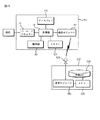
図16は、本発明の一実施例によるデジタル価格表示器及びESLサーバーからなるESLシステムを示す図である。 FIG. 16 is a diagram illustrating an ESL system including a digital price indicator and an ESL server according to an embodiment of the present invention.
図16を参照すると、ESLシステムは、商品に付着されたタグに記録された情報を読み取るタグ読み取りモジュールを備えたデジタル価格表示器101と、ESLサーバー200と、中継器500と、を含むことができる。
Referring to FIG. 16, the ESL system may include a
デジタル価格表示器101は、タグ読み取りモジュールとしてのバーコードスキャナー111と、商品に関する情報を表示するディスプレイ装置141と、ESLサーバー200と通信を行う通信モジュール(第1通信モジュール)161と、バーコードスキャナー111で読み取ったタグの情報を、通信モジュール(第1通信モジュール)161を通じてESLサーバー200に伝送し、ESLサーバー200から当該タグに関する商品情報を受信して、ディスプレイ装置141に表示させる制御部(第1制御部)181と、を含む。
The
ESLサーバー200は、デジタル価格表示器101と通信を行う通信モジュール(第2通信モジュール)180と、デジタル価格表示器101と陳列される商品に関する情報が記録されたメモリーとしての登録DB240と、デジタル価格表示器101から伝送されたデジタル価格表示器100の識別情報及び陳列される商品のタグ情報を、通信モジュール(第2通信モジュール180)を通じて受信して、登録DB240に登録させる制御部(第2制御部)220と、を含む。ここで、制御部(第2制御部)220は、タグの情報を伝送したデジタル価格表示器101と該タグに対する商品との関係を、メモリーとしての登録DB240に記録する。
The
ESLサーバー200の通信モジュール180は、別途の中継器500を介してデジタル価格表示器101と通信を行う。ESLサーバー200と中継器500とがイーサーネット等の有線ネットワークで連結された場合、通信モジュール180は、有線ネットワーク用ランカードとすれば良い。
The
以上では具体的な実施例に挙げて本発明を説明してきたが、これらの具体例は例示的なものに過ぎず、当該技術分野における通常の知識を有する者には、本発明の一実施例による表示本体を、価格及び製品情報に限定せずに、多数の品物を一目僚然に整理する必要がある時、管理者にとっては結合が容易であるが、第3者によっては容易に分離されないようにすべき場所、すなわち、簡略なタイトルや情報を表示する必要がある図書館や倉庫などにも適用することができるなど、様々な変形及び均等な範囲の実施例が可能であるということが理解できる。したがって、本発明の真の技術的保護範囲は、添付の特許請求の範囲によって定められるべきである。 Although the present invention has been described above with reference to specific embodiments, these specific examples are merely illustrative, and for those having ordinary knowledge in the art, one embodiment of the present invention. When the display body is not limited to price and product information, but it is necessary to organize a large number of items at a glance, it is easy for administrators to combine, but not easily separated by third parties It can be understood that various modifications and equivalent scope embodiments are possible, such as being applicable to places where it should be done, that is, libraries and warehouses that need to display simple titles and information. it can. Accordingly, the true technical protection scope of the present invention should be determined by the appended claims.
Claims (13)
前記陳列棚に着脱可能に結合されて、前記電源供給部から供給された電源で充電し、陳列棚に陳列される製品の価格、仕様及び広報イメージを出力する表示本体と、
前記陳列棚に設けられて、前記表示本体が固定されるとその表示本体が前記電源供給部と電気的に連結されるように、一側には陽極が形成され、他側には陰極が形成される収容具と、
前記表示本体に設けられて、前記収容具にスライディング結合して前記陽極及び陰極と電気的に連結され、前記収容具から分離されることを制限する結合具と、
を含み、
前記陳列棚には、前記結合具が結合されることで、前記表示本体を固定するフェンスが設けられ、前記収容具は、前記フェンスの長さ方向に沿って形成される、デジタル価格表示器。 A power supply unit that is mounted on a display shelf on which products are displayed and supplies power;
A display main body that is detachably coupled to the display shelf, is charged with a power source supplied from the power supply unit, and outputs a price, a specification, and a publicity image of a product displayed on the display shelf;
An anode is formed on one side and a cathode is formed on the other side so that when the display body is fixed on the display shelf, the display body is electrically connected to the power supply unit. With a storage device,
A coupling provided on the display body, slidingly coupled to the container, electrically connected to the anode and the cathode, and restricting separation from the container;
Including
The display shelf is provided with a fence for fixing the display body by being coupled with the coupling tool, and the container is formed along a length direction of the fence.
前記陽極及び前記陰極と外部電力線とを電気的に連結する蓄電池と、
前記外部電力線と前記蓄電池との間に設置されて、過負荷による前記蓄電池の損傷を防止する過負荷回路と、
を含む、請求項1に記載のデジタル価格表示器。 The power supply unit
A storage battery that electrically connects the anode and the cathode to an external power line;
An overload circuit installed between the external power line and the storage battery to prevent damage to the storage battery due to overload;
The digital price indicator of claim 1, comprising:
前記陳列棚に固定されるボディーと、
前記ボディーに内蔵されて、前記陳列棚に陳列される製品の価格、仕様及び広報イメージを転換しながら出力するディスプレイモジュールと、
前記ボディーに内蔵されて、前記サーバーと有線または無線ネットワークを通じて通信する通信モジュールと、
前記ボディーに内蔵されて、前記ディスプレイモジュールの画面出力と前記通信モジュールの通信を制御するマイクロプロセッサユニット(MPU)と、
前記ボディーに内蔵されて、前記ディスプレイモジュール、前記通信モジュール及び前記マイクロプロセッサユニットの駆動のための電源を供給する充電池と、
を含む、請求項4に記載のデジタル価格表示器。 The display body is
A body fixed to the display shelf;
A display module that is built in the body and outputs while changing the price, specifications, and publicity image of the product displayed on the display shelf;
A communication module embedded in the body and communicating with the server via a wired or wireless network;
A microprocessor unit (MPU) that is built in the body and controls screen output of the display module and communication of the communication module;
A rechargeable battery built in the body for supplying power for driving the display module, the communication module and the microprocessor unit;
The digital price indicator of claim 4, comprising:
前記レールまたは孔には、前記フェンスの長さ方向に沿って、一側に前記陽極が設けられ、他側に前記陰極が設けられる、請求項1に記載のデジタル価格表示器。 The container is a slit-shaped rail or a plurality of holes,
The digital price indicator according to claim 1, wherein the rail or the hole is provided with the anode on one side and the cathode on the other side along the length direction of the fence.
前記陳列棚に着脱可能に結合されて、前記電源供給部から供給された電源で充電し、陳列棚に陳列される製品の価格、仕様及び広報イメージを出力する表示本体と、
前記陳列棚に設けられて、前記表示本体が固定されるとその表示本体が前記電源供給部と電気的に連結されるように、一側には陽極が形成され、他側には陰極が形成される収容具と、
前記表示本体に設けられて、前記収容具にスライディング結合して前記陽極及び陰極と電気的に連結され、前記収容具から分離されることを制限する結合具と、
を含み、
前記結合具は、
前記収容具に収容されるピン形状の第1片部と、
前記収容具の幅に対応するように前記第1片部の両側に離隔形成されて弾性変形及び弾性復元を許容する第2片部と、
前記第2辺部の先端部に設けられて、前記収容具にスライディング結合して引っ掛かりながら前記表示本体の分離を制限する第1フックと、を含み、
前記第2片部の外側に前記陽極及び前記陰極と接触する電極端子が設けられて前記電源供給部と電気的に連結される、デジタル価格表示器。 A power supply unit that is mounted on a display shelf on which products are displayed and supplies power;
A display main body that is detachably coupled to the display shelf, is charged with a power source supplied from the power supply unit, and outputs a price, a specification, and a publicity image of a product displayed on the display shelf;
An anode is formed on one side and a cathode is formed on the other side so that when the display body is fixed on the display shelf, the display body is electrically connected to the power supply unit. With a storage device,
A coupling provided on the display body, slidingly coupled to the container, electrically connected to the anode and the cathode, and restricting separation from the container;
Including
The coupler is
A pin-shaped first piece housed in the container;
A second piece part formed on both sides of the first piece part so as to correspond to the width of the container and allowing elastic deformation and elastic recovery;
A first hook that is provided at a distal end of the second side part and restricts separation of the display body while being hooked by sliding coupling to the container;
The digital price indicator, wherein electrode terminals that are in contact with the anode and the cathode are provided outside the second piece and are electrically connected to the power supply unit.
前記固定具は、前記収容具と前記結合具とが結合した状態で結合される、請求項1に記載のデジタル価格表示器。 The display body further includes a fixture that slidingly couples to the coupler, limits the separation from the coupler, and both ends are fixed to the fence,
The digital price indicator according to claim 1, wherein the fixture is coupled in a state where the container and the coupling are coupled.
前記レールに対応して突出し、前記レールの形成方向と直交する方向にスリットが貫通している突条である、請求項9に記載のデジタル価格表示器。 The coupler is
The digital price indicator according to claim 9, wherein the digital price indicator is a ridge protruding corresponding to the rail and having a slit penetrating in a direction orthogonal to the rail forming direction.
前記孔に対応して突出し、前記フェンスの長さ方向と直交する方向にスリットが貫通している少なくとも一つの突起である、請求項10に記載のデジタル価格表示器。 The coupler is
11. The digital price indicator according to claim 10, wherein the digital price indicator is at least one protrusion protruding corresponding to the hole and having a slit extending in a direction perpendicular to a length direction of the fence.
前記スリットより長いまたは等しい長さの第3片部と、
前記スリットの幅に対応するように前記第3片部の両側に離隔形成されて弾性変形及び弾性復元を許容する第4片部と、
前記第3片部の一端及び前記第4片部の一端を固定し、前記スリットの一側に固定される固定片部と、
前記第4片部の他端に設けられる第2フックと、
を含む、請求項11に記載のデジタル価格表示器。 The fixture is
A third piece having a length longer than or equal to the slit;
A fourth piece part formed on both sides of the third piece part so as to correspond to the width of the slit and allowing elastic deformation and elastic recovery;
Fixing one end of the third piece part and one end of the fourth piece part, and fixing piece part fixed to one side of the slit;
A second hook provided at the other end of the fourth piece,
The digital price indicator of claim 11, comprising:
Applications Claiming Priority (4)
| Application Number | Priority Date | Filing Date | Title |
|---|---|---|---|
| KR10-2009-0102737 | 2009-10-28 | ||
| KR1020090102737A KR101753387B1 (en) | 2009-10-28 | 2009-10-28 | Digital price indicator |
| KR10-2009-0107735 | 2009-11-09 | ||
| KR1020090107735A KR101583087B1 (en) | 2009-11-09 | 2009-11-09 | Digital price displayer and esl system comprising it |
Publications (2)
| Publication Number | Publication Date |
|---|---|
| JP2011092722A JP2011092722A (en) | 2011-05-12 |
| JP5774836B2 true JP5774836B2 (en) | 2015-09-09 |
Family
ID=43924795
Family Applications (1)
| Application Number | Title | Priority Date | Filing Date |
|---|---|---|---|
| JP2010242017A Expired - Fee Related JP5774836B2 (en) | 2009-10-28 | 2010-10-28 | Digital price indicator and ESL system including the same |
Country Status (2)
| Country | Link |
|---|---|
| US (1) | US8698606B2 (en) |
| JP (1) | JP5774836B2 (en) |
Cited By (1)
| Publication number | Priority date | Publication date | Assignee | Title |
|---|---|---|---|---|
| CN109191707A (en) * | 2018-08-17 | 2019-01-11 | 厦门翔动力信息科技有限公司 | Play advertising method and mobile power source leasing system |
Families Citing this family (43)
| Publication number | Priority date | Publication date | Assignee | Title |
|---|---|---|---|---|
| US10339495B2 (en) | 2004-02-03 | 2019-07-02 | Rtc Industries, Inc. | System for inventory management |
| US8938396B2 (en) | 2004-02-03 | 2015-01-20 | Rtc Industries, Inc. | System for inventory management |
| US9898712B2 (en) | 2004-02-03 | 2018-02-20 | Rtc Industries, Inc. | Continuous display shelf edge label device |
| US9818148B2 (en) | 2013-03-05 | 2017-11-14 | Rtc Industries, Inc. | In-store item alert architecture |
| KR20110110642A (en) * | 2010-04-01 | 2011-10-07 | 엘지이노텍 주식회사 | Digital price indicator |
| US8919233B2 (en) * | 2010-12-30 | 2014-12-30 | Kimberly-Clark Worldwide, Inc. | Electronic pre-cut sheet dispenser with dispensing adjustments |
| KR101765916B1 (en) * | 2010-12-31 | 2017-08-23 | 엘지이노텍 주식회사 | An eletronic shelf label and a managing method thereof |
| WO2012154254A1 (en) * | 2011-02-16 | 2012-11-15 | Zealer Carl | Configurable advertising and content rendering |
| US20120326849A1 (en) * | 2011-06-24 | 2012-12-27 | Sensormatic Electronics, LLC | Electronic price label system and method |
| US11288472B2 (en) | 2011-08-30 | 2022-03-29 | Digimarc Corporation | Cart-based shopping arrangements employing probabilistic item identification |
| US10474858B2 (en) | 2011-08-30 | 2019-11-12 | Digimarc Corporation | Methods of identifying barcoded items by evaluating multiple identification hypotheses, based on data from sensors including inventory sensors and ceiling-mounted cameras |
| US9367770B2 (en) * | 2011-08-30 | 2016-06-14 | Digimarc Corporation | Methods and arrangements for identifying objects |
| AU2013207414B2 (en) * | 2012-01-06 | 2016-02-11 | Sunrise R&D Holdings, Llc | Display shelf modules with projectors for displaying product information and modular shelving systems comprising the same |
| FI123635B (en) * | 2012-02-14 | 2013-08-30 | Marisense Oy | Arrangement of electronic price tag |
| US9224184B2 (en) | 2012-10-21 | 2015-12-29 | Digimarc Corporation | Methods and arrangements for identifying objects |
| DE102013100987B4 (en) * | 2013-01-31 | 2023-06-29 | Phoenix Contact Gmbh & Co. Kg | connection module |
| US10357118B2 (en) | 2013-03-05 | 2019-07-23 | Rtc Industries, Inc. | Systems and methods for merchandizing electronic displays |
| US9031872B1 (en) * | 2013-03-12 | 2015-05-12 | Target Brands, Inc. | Digital sign with incorrectly stocked item identification |
| GB201403055D0 (en) * | 2014-02-21 | 2014-04-09 | Advider Ltd | A digital advertising unit |
| US20150310385A1 (en) * | 2014-04-28 | 2015-10-29 | E Smart Labels LLC | System for Managing Expiration-Dated Products |
| KR101532081B1 (en) * | 2014-09-17 | 2015-06-29 | 주식회사 라인어스 | Electronic label apparatus |
| KR102307196B1 (en) | 2014-11-03 | 2021-09-30 | (주)에이텍아이오티 | Electric Shelf Label |
| US11182738B2 (en) | 2014-11-12 | 2021-11-23 | Rtc Industries, Inc. | System for inventory management |
| US11109692B2 (en) | 2014-11-12 | 2021-09-07 | Rtc Industries, Inc. | Systems and methods for merchandizing electronic displays |
| KR20160070505A (en) | 2014-12-10 | 2016-06-20 | 엘지이노텍 주식회사 | Electric Shelf Label, Power Supply apparatus and Electric shelf Label System |
| DE102015200330A1 (en) | 2015-01-13 | 2016-07-14 | Umdasch Shopfitting Gmbh | Inclusion for electronic price tags, electronic price tag, combination of pickup and price tag, and shelf with a receptacle and / or a combination of pickup and price tag |
| EP3146871B1 (en) | 2015-01-13 | 2021-11-10 | umdasch Store Makers Management GmbH | Holder for electronic price tags |
| WO2016116663A1 (en) | 2015-01-19 | 2016-07-28 | Mariella Labels Oy | Electronic price label and a battery unit for an electronic price label |
| FI128341B (en) * | 2015-01-19 | 2020-03-31 | Marisense Oy | Electronic price label and a battery unit for an electronic price label |
| SG11201708296SA (en) * | 2015-04-10 | 2017-11-29 | Razer (Asia-Pacific) Pte Ltd | Mobile radio communication devices, communication devices, methods for controlling a mobile radio communication device, and methods for controlling a communication device |
| KR20160124542A (en) | 2015-04-20 | 2016-10-28 | 삼성전기주식회사 | Electronic shelf label and method of manufacturing the same |
| CN106203227B (en) * | 2016-06-28 | 2018-09-18 | 无锡威峰科技股份有限公司 | The method that positioning refreshing is carried out to electronic price label by graphic code |
| US20190266566A1 (en) * | 2016-09-07 | 2019-08-29 | Trevor I. Blumenau | Shelf Tag Apparatus, Systems, and Methods for Inventory Picking and Tracking |
| WO2018102058A1 (en) * | 2016-11-29 | 2018-06-07 | Walmart Apollo, Llc | Systems and methods for determining label positions |
| WO2018227060A1 (en) | 2017-06-08 | 2018-12-13 | Walmart Apollo, Llc | Methods and systems for an electronic shelf label system |
| US11293813B1 (en) | 2017-07-05 | 2022-04-05 | E Smart Labels LLC | Temperature monitoring and labeling system |
| US20190279578A1 (en) * | 2018-03-07 | 2019-09-12 | Shelfbucks, Inc. | Retail system for identifying and locating products and electronic displays, and providing environmental index information for display near relevant products |
| US10591906B2 (en) | 2018-03-14 | 2020-03-17 | Morris Controls, Inc. | Manufacturing environment management system |
| US11227293B2 (en) * | 2018-08-16 | 2022-01-18 | Best Brands Consumer Products, Inc. | Digital price display |
| US10956884B2 (en) * | 2018-10-26 | 2021-03-23 | Sunrise R&D Holdings, Llc | System and method for product display |
| JP7409774B2 (en) * | 2019-02-18 | 2024-01-09 | サトーホールディングス株式会社 | Product management support system, product management support method, and program |
| EP3751486A1 (en) | 2019-06-11 | 2020-12-16 | Solum Co., Ltd. | Electronic label management apparatus and method |
| KR20210144156A (en) | 2020-05-21 | 2021-11-30 | 주식회사 라인어스 | Electronic shelf label controlling method |
Family Cites Families (9)
| Publication number | Priority date | Publication date | Assignee | Title |
|---|---|---|---|---|
| JPH08234677A (en) * | 1994-10-06 | 1996-09-13 | Ncr Internatl Inc | Electronic display module |
| JP4003311B2 (en) * | 1998-09-09 | 2007-11-07 | ミツミ電機株式会社 | Charge control device |
| AT410382B (en) * | 2000-06-28 | 2003-04-25 | Fronius Schweissmasch Prod | Electronic circuit for fitting to a battery charging device connects an energy-supplying device to an energy source via terminals to convert energy from an AC voltage into a DC voltage and pass converted energy to a consumer. |
| US7152040B1 (en) * | 2003-05-27 | 2006-12-19 | Microsoft Corporation | Electronic shelf label |
| JP2005241752A (en) * | 2004-02-24 | 2005-09-08 | Seiko Epson Corp | Information display apparatus and information display system |
| JP2006109995A (en) * | 2004-10-13 | 2006-04-27 | Toyota Industries Corp | Article display apparatus |
| JP2008200083A (en) * | 2007-02-16 | 2008-09-04 | Sii Data Service Kk | Information display system, information display device, information display method, and program thereof |
| JP2008217738A (en) * | 2007-03-08 | 2008-09-18 | Seiko Epson Corp | Electronic price tag system and electronic price tag device |
| JP5288392B2 (en) * | 2007-06-11 | 2013-09-11 | コクヨ株式会社 | Power supply rail, power supply system, and display shelf |
-
2010
- 2010-10-27 US US12/913,444 patent/US8698606B2/en not_active Expired - Fee Related
- 2010-10-28 JP JP2010242017A patent/JP5774836B2/en not_active Expired - Fee Related
Cited By (1)
| Publication number | Priority date | Publication date | Assignee | Title |
|---|---|---|---|---|
| CN109191707A (en) * | 2018-08-17 | 2019-01-11 | 厦门翔动力信息科技有限公司 | Play advertising method and mobile power source leasing system |
Also Published As
| Publication number | Publication date |
|---|---|
| US8698606B2 (en) | 2014-04-15 |
| US20110102155A1 (en) | 2011-05-05 |
| JP2011092722A (en) | 2011-05-12 |
Similar Documents
| Publication | Publication Date | Title |
|---|---|---|
| JP5774836B2 (en) | Digital price indicator and ESL system including the same | |
| US7894081B2 (en) | Configuration recognizing system, configuration recognizing method, and computer readable medium storing configuration recognizing program of device | |
| JP4831979B2 (en) | Electronic shelf label system | |
| JPH0785159A (en) | Space management device | |
| KR20120077949A (en) | An eletronic shelf label and a managing method thereof | |
| US20110102144A1 (en) | Information display system and management device | |
| JP2007153577A (en) | Sorting system | |
| JP3814613B2 (en) | Wiring connection management system | |
| JP2010134635A (en) | Electronic shelf label and product management system | |
| JP4765357B2 (en) | Parts assembly work support system | |
| US20200251042A1 (en) | Electronic shelf display apparatus | |
| JP2008217738A (en) | Electronic price tag system and electronic price tag device | |
| JP4899811B2 (en) | Electronic POP device, control method and program for electronic POP device | |
| JP5200352B2 (en) | Electronic price tag system and electronic price tag device | |
| US20210398098A1 (en) | Information processing system, information processing method, and storage medium | |
| KR20110051076A (en) | Digital price displayer and esl system comprising it | |
| JP5245239B2 (en) | Product information display device, product information display system, control method and program for product information display system | |
| US8489471B2 (en) | Product management system and product management method | |
| JP2011048631A (en) | Electronic shelf label system | |
| JP2006033038A (en) | Optical communication system and receiver employing solar cell | |
| US20210248099A1 (en) | Information processing apparatus, information processing method, and storage medium | |
| KR20170052300A (en) | Electronic shelf label and electronic shelf label system including the same | |
| KR101753387B1 (en) | Digital price indicator | |
| JP2011090647A (en) | Information display system, management device, information display device, and electronic shelf label terminal | |
| US11966931B2 (en) | Information processing apparatus, information processing method, and storage medium |
Legal Events
| Date | Code | Title | Description |
|---|---|---|---|
| A621 | Written request for application examination |
Free format text: JAPANESE INTERMEDIATE CODE: A621 Effective date: 20131003 |
|
| A977 | Report on retrieval |
Free format text: JAPANESE INTERMEDIATE CODE: A971007 Effective date: 20140509 |
|
| A131 | Notification of reasons for refusal |
Free format text: JAPANESE INTERMEDIATE CODE: A131 Effective date: 20140701 |
|
| A521 | Request for written amendment filed |
Free format text: JAPANESE INTERMEDIATE CODE: A523 Effective date: 20141001 |
|
| A131 | Notification of reasons for refusal |
Free format text: JAPANESE INTERMEDIATE CODE: A131 Effective date: 20150224 |
|
| A521 | Request for written amendment filed |
Free format text: JAPANESE INTERMEDIATE CODE: A523 Effective date: 20150515 |
|
| TRDD | Decision of grant or rejection written | ||
| A01 | Written decision to grant a patent or to grant a registration (utility model) |
Free format text: JAPANESE INTERMEDIATE CODE: A01 Effective date: 20150602 |
|
| A61 | First payment of annual fees (during grant procedure) |
Free format text: JAPANESE INTERMEDIATE CODE: A61 Effective date: 20150702 |
|
| R150 | Certificate of patent or registration of utility model |
Ref document number: 5774836 Country of ref document: JP Free format text: JAPANESE INTERMEDIATE CODE: R150 |
|
| R250 | Receipt of annual fees |
Free format text: JAPANESE INTERMEDIATE CODE: R250 |
|
| R250 | Receipt of annual fees |
Free format text: JAPANESE INTERMEDIATE CODE: R250 |
|
| S111 | Request for change of ownership or part of ownership |
Free format text: JAPANESE INTERMEDIATE CODE: R313113 |
|
| S531 | Written request for registration of change of domicile |
Free format text: JAPANESE INTERMEDIATE CODE: R313531 |
|
| R350 | Written notification of registration of transfer |
Free format text: JAPANESE INTERMEDIATE CODE: R350 |
|
| R250 | Receipt of annual fees |
Free format text: JAPANESE INTERMEDIATE CODE: R250 |
|
| S111 | Request for change of ownership or part of ownership |
Free format text: JAPANESE INTERMEDIATE CODE: R313113 |
|
| LAPS | Cancellation because of no payment of annual fees | ||
| R350 | Written notification of registration of transfer |
Free format text: JAPANESE INTERMEDIATE CODE: R350 |