JP5765575B2 - Imaging area display device - Google Patents
Imaging area display device Download PDFInfo
- Publication number
- JP5765575B2 JP5765575B2 JP2011282208A JP2011282208A JP5765575B2 JP 5765575 B2 JP5765575 B2 JP 5765575B2 JP 2011282208 A JP2011282208 A JP 2011282208A JP 2011282208 A JP2011282208 A JP 2011282208A JP 5765575 B2 JP5765575 B2 JP 5765575B2
- Authority
- JP
- Japan
- Prior art keywords
- image
- explicit
- area
- captured
- displayed
- Prior art date
- Legal status (The legal status is an assumption and is not a legal conclusion. Google has not performed a legal analysis and makes no representation as to the accuracy of the status listed.)
- Expired - Fee Related
Links
Images

Landscapes
- Closed-Circuit Television Systems (AREA)
Description
本発明は、車両の表示画面に表示される画像の撮影領域を明示する撮影領域明示装置に関する。 The present invention relates to a photographing region specifying device that clearly shows a photographing region of an image displayed on a display screen of a vehicle.
車両の周囲には運転者の位置から視認できない死角があり、運転者は車両の運転にあたり当該車両の周囲に細心の注意を払う必要がある。特に、車両を後退して駐車させる場合には、駐車自体に苦手意識を持っているユーザも多く、精神的疲労も少なくない。そこで、従来、車両の周囲の障害物を監視する技術が利用されてきた(例えば特許文献1及び2)。
There are blind spots around the vehicle that cannot be seen from the position of the driver, and the driver needs to pay close attention to the periphery of the vehicle when driving the vehicle. In particular, when the vehicle is moved backward and parked, there are many users who are not good at parking itself, and there is not a lot of mental fatigue. Thus, conventionally, techniques for monitoring obstacles around the vehicle have been used (for example,
特許文献1に記載の車両の障害物警報装置は、横移動障害物検出手段と、横移動方向検出手段と、横移動情報提供手段とを備えて構成される。横移動障害物検出手段は車両前方において進行方向を横切る方向に移動する障害物を検出する。横移動方向検出手段は横移動障害物検出手段により検出された障害物の横移動方向を検出する。横移動情報提供手段は横移動方向検出手段により検出された障害物の横移動方向に関する情報をドライバーに提供する。この際、横移動情報提供手段は表示部に横移動方向検出手段により検出された横移動方向を表わす矢印をディスプレイに表示する。
The vehicle obstacle alarm device described in
特許文献2に記載の車両周囲監視装置は、撮像手段と、障害物検出手段と、表示手段とを備えて構成される。撮像手段は自車両の一部を含む車両周囲を撮像する。障害物検出手段は車両周囲に位置する障害物を検出し、検出した障害物と自車両との距離を算出する。表示手段は撮像手段によって撮像された撮像画像と障害物検出手段によって算出された距離を示す障害物表示画像とを1つの画面に表示する。
The vehicle surrounding monitoring apparatus described in
特許文献1や特許文献2に記載の技術のように車両の周囲の障害物を検出し、当該障害物を明示する情報(矢印等)を画面表示することで運転者に車両の周囲の障害物の存在を報知することが可能である。しかしながら、車両に搭載されるディスプレイ(表示手段)の画面サイズは大きいものではない。このため、ディスプレイに表示される車両の周囲の状況を示す画像上に矢印等を表示すると、車両の周囲の状況が見難くなったり障害物を把握できなくなったりする可能性がある。
Obstacles around the vehicle are detected by detecting obstacles around the vehicle as in the techniques described in
そこで、広視野角で撮影して取得された画像から所定の領域を切り出して表示する形態が考えられる。しかしながら、このような形態の場合には、広視野角で撮影した画像を表示しているのか、切り出した画像を表示しているのか、直感的に把握し難い。 Therefore, a form in which a predetermined region is cut out and displayed from an image obtained by photographing with a wide viewing angle is conceivable. However, in the case of such a form, it is difficult to intuitively grasp whether an image taken with a wide viewing angle is displayed or a cut image is displayed.
本発明の目的は、上記問題に鑑み、表示装置に表示される画像が、切り出す前の画像であるか、或いは切り出した後の画像であるかを運転者に明示することが可能な撮影領域明示装置を提供することにある。 In view of the above problems, an object of the present invention is to clearly indicate to the driver whether an image displayed on a display device is an image before being cut out or an image after being cut out. To provide an apparatus.
上記目的を達成するための本発明に係る撮影領域明示装置の特徴構成は、
車両の後方の情景を撮影した撮影画像を取得する撮影画像取得部と、
前記撮影画像の中央部分を注目撮影画像として生成する注目撮影画像生成部と、
表示画面に表示されている、前記撮影画像を用いて生成された画像の撮影領域が、前記撮影画像に対応する撮影領域であるか、或いは前記注目撮影画像に対応する撮影領域であるかを、前記注目撮影画像に対応する撮影領域を示す第1明示領域、及び当該第1明示領域の横方向両側に当該第1明示領域と共に前記撮影画像の撮影領域を示す第2明示領域の少なくとも一方を用いて明示する撮影領域明示画像を生成する撮影領域明示画像生成部と、
前記表示画面に前記撮影画像と共に、前記第1明示領域と前記第2明示領域とからなる撮影領域明示画像が表示されている際に、前記第1明示領域と前記第2明示領域との境界に、前記注目撮影画像に対応する撮影領域の境界を明示する境界明示画像を表示する境界明示画像生成部と、
を備えている点にある。
In order to achieve the above object, the characteristic configuration of the imaging region specifying device according to the present invention is as follows:
A captured image acquisition unit that acquires a captured image of a scene behind the vehicle;
A noticeable photographed image generating unit for generating a central part of the photographed image as a noticeable photographed image;
Is displayed on the display screen, the imaging area of the image that is generated using the captured image, the or the captured image is an imaging area corresponding, or whether the imaging area corresponding to the target captured images, At least one of a first explicit area indicating a shooting area corresponding to the target captured image and a second explicit area indicating a shooting area of the captured image together with the first explicit area on both lateral sides of the first explicit area is used. a photographing area expressly image generation unit for generating a manifest imaging area expressly image Te,
When a shooting area explicit image composed of the first explicit area and the second explicit area is displayed together with the shot image on the display screen, the boundary between the first explicit area and the second explicit area is displayed. , the boundary explicit image generation unit that displays demonstrating boundaries explicit image boundaries of the imaging area corresponding to the target captured images,
It is in the point equipped with.
このような特徴構成とすれば、車両の表示装置(モニタ)に撮影画像取得部により取得された撮影画像が表示されている場合には撮影領域明示画像内に境界明示画像を含んで表示され、表示装置に撮影画像取得部により取得された撮影画像に基づいて生成された注目撮影画像が表示されている場合には撮影領域明示画像内に境界明示画像が含まれないので、車両の乗員は境界明示画像の有無により表示装置に表示されている画像の種別を特定することが可能となる。このため、乗員が表示装置に表示されている画像の撮影領域を直感的に認識し易くなる。このように、本発明によれば、表示装置に表示される画像が、撮影画像取得部により取得された撮影画像(切り出す前の画像)であるか、或いは撮影画像に基づいて生成された注目撮影画像(切り出した後の画像)であるかを運転者に明示することができる。 With such a feature configuration, when the captured image acquired by the captured image acquisition unit is displayed on the display device (monitor) of the vehicle, the boundary explicit image is displayed in the captured region explicit image, When the attention photographed image generated based on the photographed image acquired by the photographed image acquisition unit is displayed on the display device, the boundary explicit image is not included in the photographing region explicit image. The type of image displayed on the display device can be specified by the presence or absence of the explicit image. For this reason, it becomes easy for an occupant to intuitively recognize the imaging region of the image displayed on the display device. As described above, according to the present invention, the image displayed on the display device is the captured image (the image before being cut out) acquired by the captured image acquisition unit, or the captured image of interest generated based on the captured image. Whether it is an image (image after being cut out) can be clearly shown to the driver.
また、前記撮影領域明示画像は半透明であり、前記表示画面に表示されている画像に重畳して表示される構成とすると好適である。 In addition, it is preferable that the photographing region explicit image is translucent and is displayed so as to be superimposed on the image displayed on the display screen.
このような構成とすれば、撮影領域明示画像が重畳された撮影画像や注目撮影画像が見えなくなることを防止できる。したがって、撮影領域明示画像を表示したことによる車両の周囲の情景の見落としを避けることができる。 With such a configuration, it is possible to prevent the photographed image or the noticeable photographed image on which the photographing region explicit image is superimposed from becoming invisible. Therefore, it is possible to avoid oversight of a scene around the vehicle due to the display of the shooting area explicit image.
また、前記撮影領域明示画像は、前記表示画面の上部に配置されると好適である。 In addition, it is preferable that the shooting area explicit image is arranged at an upper portion of the display screen.
一般的に、表示画面の上部には空が映る。したがって、撮影領域明示画像を表示画面の上部に配置した場合には、車両の周囲の情景が隠れることを防ぐことができる。 Generally, the sky appears at the top of the display screen. Therefore, when the shooting area explicit image is arranged at the upper part of the display screen, it is possible to prevent the scene around the vehicle from being hidden.
また、前記撮影領域明示画像生成部は、前記表示画面の表示が、前記撮影画像から前記注目撮影画像に変更される場合に、前記撮影領域明示画像のうち、前記注目撮影画像に対応する撮影領域のみを拡大する構成とすると好適である。 Further, the imaging region explicit image generation unit, when the display on the display screen is changed from the captured image to the focused captured image, the captured region corresponding to the focused captured image in the captured region explicit image. It is preferable that only the configuration is enlarged.
このような構成とすれば、撮影画像に映る物体が、注目撮影画像においては拡大して表示されることになる。したがって、車両の乗員が物体を見落とすことを防止できる。 With such a configuration, an object appearing in the captured image is enlarged and displayed in the focused captured image. Therefore, it is possible to prevent the vehicle occupant from overlooking the object.
また、前記撮影領域明示画像に、少なくとも前記車両の後部の鳥瞰画像が含まれると好適である。 In addition, it is preferable that at least a bird's-eye view of the rear portion of the vehicle is included in the imaging region explicit image.
このような構成とすれば、車両の乗員が当該車両との位置関係を容易に認識し易くすることができる。 With such a configuration, a vehicle occupant can easily recognize the positional relationship with the vehicle.
以下、本発明の実施の形態について、詳細に説明する。本発明に係る撮影領域明示装置100は、車両のモニタにカメラで撮影して取得した画像を表示する際、撮影領域を明示する機能を備えている。以下、図面を用いて説明する。
Hereinafter, embodiments of the present invention will be described in detail. The imaging
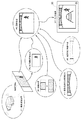
図1は、撮影領域明示装置100の構成を模式的に示したブロック図である。図1に示されるように、撮影領域明示装置100は、撮影画像取得部11、注目撮影画像生成部12、画像決定部16、撮影領域明示画像生成部17、合成画像生成部18、境界明示画像生成部19の各機能部を備えて構成される。各機能部はCPUを中核部材として車両1の乗員にモニタ50に表示される画像の撮影領域を明示する種々の処理を行うための上述の機能部がハードウェア又はソフトウェア或いはその両方で構築されている。
FIG. 1 is a block diagram schematically showing the configuration of the imaging
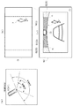
撮影画像取得部11は、車両1の後方の情景を撮影した撮影画像Gを取得する。ここで、車両1にはカメラ5が備えられる。本実施形態におけるカメラ5は、CCD(charge coupled device)やCIS(CMOS image sensor)などの撮像素子を内蔵するとともに、撮影した情報を動画情報として出力するデジタルカメラにより構成される。このようなカメラ5は、図2(a)に示されるように、車両1の外側後部に備えられるライセンスプレートの近傍、或いは車両1の外側後部に備えられるエンブレムの近傍等に、車両1の後方に向けてやや俯角を有して配設される。また、カメラ5は広角レンズ(図示せず)を備えて構成される。これにより、車両1の後方を略180度に亘って、車両1の周囲の情景を撮影することができる。このような撮影範囲は、図2(a)の「広視野角」として示される。このカメラ5は、リアルタイムで動画を撮影画像Gとして出力する性能を有する。このような撮影画像Gは、撮影画像取得部11に伝達される。
The captured
このような撮影画像Gの一例が図2(b)に示される。図2(b)の全幅は、図2(a)の広視野角に対応する。ここで、撮影画像Gは、図2(a)に示されるような車両1から後方を見て左側にいる物体7が、図2(b)に示されるように撮影画像G内の右側にいるように鏡像処理が行われる。これは、モニタ50に車両1の後方の情景を表示する際、車両1の運転者が撮影画像Gに含まれる物体7が車両1の左側にいるのか右側にいるのかを感覚的に理解し易くするためである。
An example of such a captured image G is shown in FIG. The full width of FIG. 2 (b) corresponds to the wide viewing angle of FIG. 2 (a). Here, in the photographed image G, the
図1に戻り、注目撮影画像生成部12は、撮影画像Gに基づいて注目撮影画像Cを生成する。本実施形態では、撮影画像Gの撮影範囲は広視野角である。このため、注目撮影画像生成部12は、撮影画像Gの中央部分である狭視野領域Nを注目撮影画像Cとして生成する。撮影画像Gは上述の撮影画像取得部11から伝達される。本実施形態では、注目撮影画像Cは、図2(b)に示される撮影画像Gの横方向の中央部分が相当する。このような狭視野領域Nは、図1(a)の「狭視野角」のような例えば車両1の後方120〜130度程度の領域とすると好適である。また、狭視野領域Nは車両1が後退する際の進行可能範囲に近いので、撮影画像Gのうち特に注目すべき領域であることから「注目撮影画像」と称される。このような注目撮影画像Cは、後述するモニタ50に表示される表示画像に対応する(図2(c)参照)。なお、本実施形態では、「注目撮影画像」は「狭視野領域」の画像であるとして説明する。
Returning to FIG. 1, the noticeable photographed
画像決定部16は、モニタ50に撮影画像Gを表示するか、注目撮影画像Cを表示するかを決定する。この決定は、車両1の乗員によるスイッチの操作に応じて行っても良いし、本撮影領域明示装置100の上位システムからの命令により行ってもよい。乗員のスイッチの操作による場合には、図示はしないがメカ的なスイッチを設けることも可能であるし、モニタ50をタッチパネルで構成した場合には当該タッチパネルへのタッチ入力による形態とすることも可能である。画像決定部16によるいずれの画像を表示するかを示す決定結果は撮影領域明示画像生成部17及び合成画像生成部18に伝達される。
The
撮影領域明示画像生成部17は、表示画面(モニタ50)に表示されている画像の撮影領域が、撮影画像Gに対応する撮影領域か注目撮影画像Cに対応する撮影領域かを明示する撮影領域明示画像Sを生成する。モニタ50に撮影画像Gが表示されているか又は注目撮影画像Cが表示されているかは、上述の画像決定部16から伝達される検出結果に基づき特定することが可能である。撮影領域明示画像Sは、車両1の乗員にモニタ50に表示されている画像の撮影領域を示す画像である。
The shooting area explicit
撮影領域明示画像Sには、少なくとも車両1の後部の鳥瞰画像が含まれる。本実施形態では、図2(c)に示されるように、車両1の後部の鳥瞰画像が示される。この鳥瞰画像は、予め自車の写真を取得しておいたものを表示しても良いし、或いは写真ではないイメージ画像を表示しても良い。本実施形態では、イメージ画像として自車イメージ画像CIが表示される。撮影領域明示画像Sは、モニタ50の横方向中央部に注目撮影領域の撮影領域を示す第1明示領域S1と、当該第1明示領域S1の横方向両側に当該第1明示領域S1と共に撮影画像Gの撮影領域を示す第2明示領域S2とで構成される。すなわち、第1明示領域S1で注目撮影画像Cの撮影領域を示し、第1明示領域S1及び第2明示領域S2で撮影画像Gの撮影領域を示す。
The imaging region explicit image S includes at least a bird's-eye image of the rear part of the
したがって、モニタ50に撮影画像Gが表示されている場合には撮影領域明示画像Sとして、第1明示領域S1、第2明示領域S2、及び自車イメージ画像CIが表示される。一方、モニタ50に注目撮影画像Cが表示されている場合には撮影領域明示画像Sとして、第1明示領域S1及び自車イメージ画像CIが表示される。
Therefore, when the captured image G is displayed on the
また、モニタ50の表示が、撮影画像Gから注目撮影画像Cに変更される場合に、撮影領域明示画像Sのうち、注目撮影画像Cに対応する撮影領域のみを拡大する。ここで、モニタ50に表示される画像のサイズは、モニタ50の表示サイズに合わせて拡大または縮小して表示される。このため、モニタ50の表示を、広視野角の撮影画像Gから当該狭視野角の注目撮影画像Cに切り替える場合には、撮影画像Gの一部が切り出されて拡大して表示されることになる。したがって、撮影画像G及び注目撮影画像Cに同一の物体7が含まれる場合には、当該物体7の表示画面内のサイズは撮影画像Gの場合よりも注目撮影画像Cの場合の方が大きくなる。
Further, when the display of the
撮影領域明示画像生成部17は、このような撮影画像Gから注目撮影画像Cに切り替える場合には、事前に第1明示領域S1及び自車イメージ画像CIを拡大して表示し、その後、注目撮影画像Cに切り替える。これにより、乗員に前もってモニタ50の表示が、撮影画像Gから注目撮影画像Cに切り替えられることを暗示することが可能となる。
The imaging region explicit
本実施形態では、このような撮影領域明示画像生成部17は、第1明示領域S1を拡大する前に、撮影領域明示画像Sの少なくとも一部を点滅させる。本実施形態では、第1明示領域S1を所定時間点滅させる。これにより、乗員に対して第1明示領域S1が拡大されることを暗示できると共に、その後、注目撮影画像Cが表示されることを暗示することが可能となる。
In the present embodiment, such an imaging area explicit
境界明示画像生成部19は、モニタ50に撮影画像Gに対応する撮影領域を示す撮影領域明示画像Sが表示されている際に、注目撮影画像Cに対応する撮影領域の境界を明示する境界明示画像Kを表示する。撮影画像Gに対応する撮影領域を示す撮影領域明示画像Sとは、第1明示領域S1及び第2明示領域S2である。一方、モニタ50に注目撮影画像Cが表示されている場合には、当該注目撮影画像Cに対応する撮影領域を示す第1明示領域S1が表示される。したがって、注目撮影画像Cに対応する撮影領域の境界とは、第1明示領域S1と第2明示領域S2との境界が相当する。境界明示画像生成部19は、このような第1明示領域S1と第2明示領域S2との境界に境界明示画像Kを表示する。本実施形態では、境界明示画像Kは、第1明示領域S1と第2明示領域S2との境界において、カメラ5で撮影して取得された画像をそのまま表示させる無色透明の画像である。
The boundary explicit
合成画像生成部18は、撮影画像G及び注目撮影画像Cの一方と、撮影領域明示画像Sとを合成してモニタ50に表示させる表示を生成する。上述のように、モニタ50には、撮影画像G及び注目撮影画像Cの一方が表示される。合成画像生成部18は、これらのうちの一方と撮影領域明示画像Sを合成する。撮影画像G及び注目撮影画像Cのいずれを用いるかは、上述の画像決定部16からの決定結果に基づき特定される。また、撮影領域明示画像Sは、画像決定部16による決定結果に基づき撮影領域明示画像生成部17により生成され、合成画像生成部18に伝達される。以上により、合成画像生成部18は、所定の画像と、撮影領域明示画像Sとを合成する。これによりモニタ50に適切な画像が表示される。
The composite
ここで、撮影領域明示画像Sは半透明であり、モニタ50に表示されている画像に重畳して表示される。これにより、車両1の周囲の状況を示す撮影画像G又は注目撮影画像Cに撮影領域明示画像Sを重畳した場合でも、乗員が車両1の周囲の状況の視認性が妨げられることはない。
Here, the imaging region explicit image S is translucent, and is displayed superimposed on the image displayed on the
また、撮影領域明示画像Sは、表示画面の上部に配置される。ここで、一般的にモニタ50に表示される画面の上部には、空が表示される。したがって、このような空の部分に撮影領域明示画像Sを表示することにより、車両1の周囲の状況の視認性が悪化することを防止できる。
In addition, the imaging region explicit image S is arranged at the top of the display screen. Here, sky is generally displayed at the top of the screen displayed on the
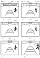
上述の境界明示画像Kを重畳して表示する一連の画像の一例が、図3に示される。図3(a)においては、広視野角の撮影画像Gが表示されている。この場合には、表示画面の上部に、撮影画像Gの撮影領域を示す第1明示領域S1及び第2明示領域S2も表示される。更には、自車イメージ画像CIも表示される。また、第1明示領域S1と第2明示領域S2との間には、境界明示画像Kが表示される。 An example of a series of images displayed by superimposing the above-described boundary explicit image K is shown in FIG. In FIG. 3A, a captured image G with a wide viewing angle is displayed. In this case, the first explicit area S1 and the second explicit area S2 indicating the shooting area of the shot image G are also displayed at the top of the display screen. Furthermore, the vehicle image CI is also displayed. A boundary explicit image K is displayed between the first explicit area S1 and the second explicit area S2.
この状態で、乗員により注目撮影画像Cへの切り替え操作が行われると、図3(a)及び(b)を所定の回数だけ繰り返すことにより第1明示領域S1の点滅が行われる。これにより、撮影画像Gが注目撮影画像Cに切り替えられることを暗示することができる。その後、第1明示領域S1が表示画面の横方向のサイズになるまで徐々に拡大される(図3(c)及び(e))。 In this state, when the occupant performs a switching operation to the noticed captured image C, the first explicit area S1 is blinked by repeating FIGS. 3A and 3B a predetermined number of times. Thereby, it can be implied that the photographed image G is switched to the noticeable photographed image C. Thereafter, the first explicit area S1 is gradually enlarged until it reaches the horizontal size of the display screen (FIGS. 3C and 3E).
第1明示領域S1が拡大されると、その後、車両1の後方の状況を示す画像も、撮影画像Gから注目撮影画像Cに切り替えられる(図3(f))。このような境界明示画像Kを表示画面内に表示することにより、車両1の乗員が表示画面に表示される画像の種別を直感的に把握することができる。
When the first explicit area S1 is enlarged, the image indicating the situation behind the
また、モニタ50に注目撮影画像Cが表示される場合には、上述のように撮影領域明示画像Sとして、第1明示領域S1のみが表示され、第2明示領域S2が表示されないので、境界明示画像Kは表示されない(図3(f)参照)。
Further, when the noticed photographed image C is displayed on the
次に、撮影領域明示装置100が、境界明示画像Kを表示する一連の処理について、図4の模式図を用いて説明する。まず、撮影画像取得部11が、車両1のカメラ5により撮影された撮影画像Gを取得する(ステップ#1)。
Next, a series of processes in which the imaging
次に、注目撮影画像生成部12が、取得された撮影画像Gの中央部分を注目撮影画像Cとして生成する(ステップ#2)。一方、画像決定部16が、モニタ50に表示する画像を撮影画像Gにするか、或いは注目撮影画像Cにするかを決定する(ステップ#3)。また、撮影領域明示画像生成部17により、撮影領域明示画像Sが生成される(ステップ#4)。更に、また、境界明示画像生成部19が、第1明示領域S1と第2明示領域S2との境界を示す境界明示画像Kを生成する(ステップ#5)。
Next, the noticeable captured
合成画像生成部18は、ステップ#1において取得された撮影画像G、及びステップ#2において生成された注目撮影画像Cから、ステップ#3により決定された画像を選択し、当該選択された画像に、ステップ#4で生成された撮影領域明示画像Sを重畳して合成画像を生成する(ステップ#6)。この際、画像決定部16により、撮影画像Gが表示されると決定された場合には、境界明示画像生成部19により生成された境界明示画像Kも合成される。生成された合成画像は、モニタ50に表示される(ステップ#7)。このように撮影画像G又は注目撮影画像Cに撮影領域明示画像Sを重畳して表示することにより車両1の乗員にモニタ50に表示される画像の撮影範囲を明示することが可能となる。
The composite
このように本発明に係る撮影領域明示装置100によれば、車両1のモニタ50に撮影画像取得部11により取得された撮影画像Gが表示されている場合には撮影領域明示画像S内に境界明示画像Kを含んで表示され、モニタ50に撮影画像取得部11により取得された撮影画像Gに基づいて生成された注目撮影画像Cが表示されている場合には撮影領域明示画像S内に境界明示画像Kが含まれないので、車両1の乗員は境界明示画像Kの有無によりモニタ50に表示されている画像の種別を特定することが可能となる。このため、乗員がモニタ50に表示されている画像の撮影領域を直感的に認識し易くなる。このように、本発明によれば、モニタ50に表示される画像が、カメラ5で撮影した画像(撮影画像G)であるのか、或いは撮影画像Gの一部の画像(注目撮影画像)であるかを運転者に明示することができる。
As described above, according to the imaging region
〔その他の実施形態〕
上記実施形態では、境界明示画像Kが撮影画像Gの画像をそのまま表示するものであるとして説明した。しかしながら、本発明の適用範囲はこれに限定されるものではない。境界明示画像Kを所定の色で彩色して構成することも可能である。
[Other Embodiments]
In the above-described embodiment, the boundary explicit image K is described as displaying the image of the captured image G as it is. However, the scope of application of the present invention is not limited to this. It is also possible to construct the boundary explicit image K by coloring it with a predetermined color.
上記実施形態では、撮影領域明示画像生成部17は、第1明示領域S1の拡大を行う前に、第1明示領域S1を点滅させるとして説明した。しかしながら、本発明の適用範囲はこれに限定されるものではない。第1明示領域S1を点滅させないように構成することも当然に可能である。或いは、第1明示領域S1を点灯させるように構成することも当然に可能である。また、撮影領域明示画像S全体を点滅させるように構成することも可能である。
In the above embodiment, the imaging area explicit
また、撮影領域明示画像生成部17は、第1明示領域S1の拡大を行う前に、第1明示領域S1を点滅させるだけでなく、モニタ50の表示を注目撮影画像Cから撮影画像Gに切り替える際において、第1明示領域S1の縮小を行う前に、第1明示領域S1を点滅させる構成とすることも当然に可能である。
Further, the shooting area explicit
上記実施形態では、撮影領域明示画像Sは半透明であるとして説明した。しかしながら、本発明の適用範囲はこれに限定されるものではない。撮影領域明示画像Sを半透明にすることなく、すなわち透明度を0%として構成することも当然に可能である。また、半透明とは、透明度が50%に限定されるものではなく、フレキシブルに変更することが可能である(0%<透明度<100%に変更することが可能である)。 In the above embodiment, the imaging region explicit image S has been described as being translucent. However, the scope of application of the present invention is not limited to this. Of course, it is also possible to configure the imaging region explicit image S without making it semi-transparent, that is, with a transparency of 0%. The term “translucent” means that the transparency is not limited to 50% and can be changed flexibly (0% <transparency <100% can be changed).
上記実施形態では、撮影領域明示画像Sは、表示画面の上部に配置されるとして説明した。しかしながら、本発明の適用範囲はこれに限定されるものではない。撮影領域明示画像Sを表示画像の上部以外の位置に表示することも当然に可能である。 In the above embodiment, the imaging region explicit image S has been described as being arranged at the top of the display screen. However, the scope of application of the present invention is not limited to this. Of course, it is also possible to display the imaging region explicit image S at a position other than the upper part of the display image.
上記実施形態では、画像決定部16は乗員のスイッチ操作や上位システムによりモニタ50に表示する画像を決定するとして説明した。しかしながら、本発明の適用範囲はこれに限定されるものではない。例えば、車両1に当該車両1に接近する物体7を検知する物体検知手段を備え、当該物体検知手段が物体7を検知した場合に画像を切り替える構成とすることも可能である。このような物体検知手段として、カメラ5により取得された撮影画像Gを用いて画像認識処理を行って物体7を検知する構成とすることも可能であるし、車両1に例えばソナーを搭載し、当該ソナーの検出結果に基づき物体7を検知する構成とすることも可能である。もちろん、他の検知手段を備えて検知する構成とすることも当然に可能である。
In the above-described embodiment, the
上記実施形態では、撮影領域明示画像生成部17は、モニタ50の表示が、撮影画像Gから注目撮影画像Cに変更される場合に、撮影領域明示画像Sのうち、注目撮影画像Cに対応する撮影領域のみを拡大するとして説明した。しかしながら、本発明の適用範囲はこれに限定されるものではない。別途用意した注目撮影画像Cを表示する構成とすることも当然に可能である。
In the above-described embodiment, when the display on the
上記実施形態では、撮影領域明示画像Sに、少なくとも車両1の後部の鳥瞰画像が含まれるとして説明した。しかしながら、本発明の適用範囲はこれに限定されるものではない。撮影領域明示画像Sに、車両1の後部の鳥瞰画像を含まずに構成することも可能である。また、撮影領域明示画像Sに、車両1の全体の鳥瞰画像を含んで構成することも当然に可能である。
In the above embodiment, the imaging region explicit image S has been described as including at least the bird's-eye view of the rear portion of the
本発明は、車両に接近する障害物の存在を乗員に明示する撮影領域明示装置に関する。 The present invention relates to an imaging region indicating device that clearly indicates to an occupant the presence of an obstacle approaching a vehicle.
1:車両
11:撮影画像取得部
12:注目撮影画像生成部
17:撮影領域明示画像生成部
19:境界明示画像生成部
100:撮影領域明示装置
C:注目撮影画像
G:撮影画像
S:撮影領域明示画像
K:境界明示画像
DESCRIPTION OF SYMBOLS 1: Vehicle 11: Captured image acquisition unit 12: Attention captured image generation unit 17: Shooting region explicit image generation unit 19: Boundary explicit image generation unit 100: Shooting region explicit device C: Attention captured image G: Captured image S: Imaging region Explicit image K: Boundary explicit image
Claims (5)
前記撮影画像の中央部分を注目撮影画像として生成する注目撮影画像生成部と、
表示画面に表示されている、前記撮影画像を用いて生成された画像の撮影領域が、前記撮影画像に対応する撮影領域であるか、或いは前記注目撮影画像に対応する撮影領域であるかを、前記注目撮影画像に対応する撮影領域を示す第1明示領域、及び当該第1明示領域の横方向両側に当該第1明示領域と共に前記撮影画像の撮影領域を示す第2明示領域の少なくとも一方を用いて明示する撮影領域明示画像を生成する撮影領域明示画像生成部と、
前記表示画面に前記撮影画像と共に、前記第1明示領域と前記第2明示領域とからなる撮影領域明示画像が表示されている際に、前記第1明示領域と前記第2明示領域との境界に、前記注目撮影画像に対応する撮影領域の境界を明示する境界明示画像を表示する境界明示画像生成部と、
を備える撮影領域明示装置。 A captured image acquisition unit that acquires a captured image of a scene behind the vehicle;
A noticeable photographed image generating unit for generating a central part of the photographed image as a noticeable photographed image;
Is displayed on the display screen, the imaging area of the image that is generated using the captured image, the or the captured image is an imaging area corresponding, or whether the imaging area corresponding to the target captured images, At least one of a first explicit area indicating a shooting area corresponding to the target captured image and a second explicit area indicating a shooting area of the captured image together with the first explicit area on both lateral sides of the first explicit area is used. a photographing area expressly image generation unit for generating a manifest imaging area expressly image Te,
When a shooting area explicit image composed of the first explicit area and the second explicit area is displayed together with the shot image on the display screen, the boundary between the first explicit area and the second explicit area is displayed. , the boundary explicit image generation unit that displays demonstrating boundaries explicit image boundaries of the imaging area corresponding to the target captured images,
An imaging region specifying device comprising:
Priority Applications (2)
| Application Number | Priority Date | Filing Date | Title |
|---|---|---|---|
| JP2011282208A JP5765575B2 (en) | 2011-12-22 | 2011-12-22 | Imaging area display device |
| PCT/JP2012/079405 WO2013094345A1 (en) | 2011-12-22 | 2012-11-13 | Imaging-region-specifying device |
Applications Claiming Priority (1)
| Application Number | Priority Date | Filing Date | Title |
|---|---|---|---|
| JP2011282208A JP5765575B2 (en) | 2011-12-22 | 2011-12-22 | Imaging area display device |
Publications (2)
| Publication Number | Publication Date |
|---|---|
| JP2013132024A JP2013132024A (en) | 2013-07-04 |
| JP5765575B2 true JP5765575B2 (en) | 2015-08-19 |
Family
ID=48909239
Family Applications (1)
| Application Number | Title | Priority Date | Filing Date |
|---|---|---|---|
| JP2011282208A Expired - Fee Related JP5765575B2 (en) | 2011-12-22 | 2011-12-22 | Imaging area display device |
Country Status (1)
| Country | Link |
|---|---|
| JP (1) | JP5765575B2 (en) |
Family Cites Families (3)
| Publication number | Priority date | Publication date | Assignee | Title |
|---|---|---|---|---|
| JP4654723B2 (en) * | 2005-03-22 | 2011-03-23 | 日産自動車株式会社 | Video display device and video display method |
| JP2008301091A (en) * | 2007-05-30 | 2008-12-11 | Aisin Seiki Co Ltd | Periphery-monitoring system for vehicle |
| JP5696872B2 (en) * | 2010-03-26 | 2015-04-08 | アイシン精機株式会社 | Vehicle periphery monitoring device |
-
2011
- 2011-12-22 JP JP2011282208A patent/JP5765575B2/en not_active Expired - Fee Related
Also Published As
| Publication number | Publication date |
|---|---|
| JP2013132024A (en) | 2013-07-04 |
Similar Documents
| Publication | Publication Date | Title |
|---|---|---|
| JP5692403B2 (en) | Obstacle alarm device | |
| JP6014442B2 (en) | Image generation apparatus, image display system, and image generation method | |
| JP5099451B2 (en) | Vehicle periphery confirmation device | |
| JP5500369B2 (en) | Vehicle peripheral image generation device | |
| WO2013065341A1 (en) | Obstacle alert device | |
| JP2010130647A (en) | Vehicle periphery checking system | |
| JP5131152B2 (en) | Visual support device | |
| JP5861449B2 (en) | Obstacle alarm device | |
| JP5660395B2 (en) | Obstacle alarm device | |
| JP5845909B2 (en) | Obstacle alarm device | |
| JP5974476B2 (en) | Obstacle alarm device | |
| JPWO2019216087A1 (en) | Image processors, mobile devices, and methods, and programs | |
| WO2013065122A1 (en) | Obstacle alert device | |
| JP5754605B2 (en) | Obstacle alarm device | |
| JP5787168B2 (en) | Obstacle alarm device | |
| JP5704416B2 (en) | Obstacle alarm device | |
| JP5765575B2 (en) | Imaging area display device | |
| JP5765576B2 (en) | Obstacle alarm device | |
| JP5825091B2 (en) | Imaging area display device | |
| KR102125738B1 (en) | A parking assisting system | |
| WO2013094345A1 (en) | Imaging-region-specifying device | |
| JP5704417B2 (en) | Obstacle alarm device | |
| JP5674071B2 (en) | Obstacle alarm device | |
| JP2013131178A (en) | Obstacle alarm device | |
| WO2013094496A1 (en) | Obstacle alarm device |
Legal Events
| Date | Code | Title | Description |
|---|---|---|---|
| A621 | Written request for application examination |
Free format text: JAPANESE INTERMEDIATE CODE: A621 Effective date: 20140217 |
|
| A131 | Notification of reasons for refusal |
Free format text: JAPANESE INTERMEDIATE CODE: A131 Effective date: 20150226 |
|
| A521 | Request for written amendment filed |
Free format text: JAPANESE INTERMEDIATE CODE: A523 Effective date: 20150403 |
|
| TRDD | Decision of grant or rejection written | ||
| A01 | Written decision to grant a patent or to grant a registration (utility model) |
Free format text: JAPANESE INTERMEDIATE CODE: A01 Effective date: 20150521 |
|
| A61 | First payment of annual fees (during grant procedure) |
Free format text: JAPANESE INTERMEDIATE CODE: A61 Effective date: 20150603 |
|
| R151 | Written notification of patent or utility model registration |
Ref document number: 5765575 Country of ref document: JP Free format text: JAPANESE INTERMEDIATE CODE: R151 |
|
| LAPS | Cancellation because of no payment of annual fees |