JP5765086B2 - Terahertz wave generator, camera, imaging device, and measuring device - Google Patents
Terahertz wave generator, camera, imaging device, and measuring device Download PDFInfo
- Publication number
- JP5765086B2 JP5765086B2 JP2011141089A JP2011141089A JP5765086B2 JP 5765086 B2 JP5765086 B2 JP 5765086B2 JP 2011141089 A JP2011141089 A JP 2011141089A JP 2011141089 A JP2011141089 A JP 2011141089A JP 5765086 B2 JP5765086 B2 JP 5765086B2
- Authority
- JP
- Japan
- Prior art keywords
- light source
- terahertz wave
- pulse
- light
- electrodes
- Prior art date
- Legal status (The legal status is an assumption and is not a legal conclusion. Google has not performed a legal analysis and makes no representation as to the accuracy of the status listed.)
- Expired - Fee Related
Links
- 238000003384 imaging method Methods 0.000 title claims description 23
- 230000003287 optical effect Effects 0.000 claims description 74
- 230000006835 compression Effects 0.000 claims description 51
- 238000007906 compression Methods 0.000 claims description 51
- 238000001514 detection method Methods 0.000 claims description 46
- 238000005259 measurement Methods 0.000 claims description 14
- 239000004065 semiconductor Substances 0.000 claims description 8
- 238000009826 distribution Methods 0.000 description 30
- 239000000758 substrate Substances 0.000 description 23
- 238000005253 cladding Methods 0.000 description 14
- 230000003321 amplification Effects 0.000 description 13
- 238000003199 nucleic acid amplification method Methods 0.000 description 13
- 239000000126 substance Substances 0.000 description 13
- 238000000034 method Methods 0.000 description 10
- 238000005530 etching Methods 0.000 description 9
- 238000005549 size reduction Methods 0.000 description 7
- 238000010586 diagram Methods 0.000 description 6
- 238000011088 calibration curve Methods 0.000 description 5
- 238000003860 storage Methods 0.000 description 5
- OMOVVBIIQSXZSZ-UHFFFAOYSA-N [6-(4-acetyloxy-5,9a-dimethyl-2,7-dioxo-4,5a,6,9-tetrahydro-3h-pyrano[3,4-b]oxepin-5-yl)-5-formyloxy-3-(furan-3-yl)-3a-methyl-7-methylidene-1a,2,3,4,5,6-hexahydroindeno[1,7a-b]oxiren-4-yl] 2-hydroxy-3-methylpentanoate Chemical compound CC12C(OC(=O)C(O)C(C)CC)C(OC=O)C(C3(C)C(CC(=O)OC4(C)COC(=O)CC43)OC(C)=O)C(=C)C32OC3CC1C=1C=COC=1 OMOVVBIIQSXZSZ-UHFFFAOYSA-N 0.000 description 4
- 230000000694 effects Effects 0.000 description 4
- 230000005540 biological transmission Effects 0.000 description 3
- 238000000701 chemical imaging Methods 0.000 description 3
- 239000004020 conductor Substances 0.000 description 3
- 239000006185 dispersion Substances 0.000 description 3
- 229910000980 Aluminium gallium arsenide Inorganic materials 0.000 description 2
- 229910001218 Gallium arsenide Inorganic materials 0.000 description 2
- 239000006096 absorbing agent Substances 0.000 description 2
- 238000010521 absorption reaction Methods 0.000 description 2
- 230000004888 barrier function Effects 0.000 description 2
- 238000001228 spectrum Methods 0.000 description 2
- 238000004458 analytical method Methods 0.000 description 1
- 239000000470 constituent Substances 0.000 description 1
- 230000001066 destructive effect Effects 0.000 description 1
- 230000005684 electric field Effects 0.000 description 1
- 239000002117 illicit drug Substances 0.000 description 1
- 238000007689 inspection Methods 0.000 description 1
- NLYAJNPCOHFWQQ-UHFFFAOYSA-N kaolin Chemical compound O.O.O=[Al]O[Si](=O)O[Si](=O)O[Al]=O NLYAJNPCOHFWQQ-UHFFFAOYSA-N 0.000 description 1
- 238000004519 manufacturing process Methods 0.000 description 1
- 239000000463 material Substances 0.000 description 1
- 239000011159 matrix material Substances 0.000 description 1
- 230000010363 phase shift Effects 0.000 description 1
Images


Classifications
-
- G—PHYSICS
- G01—MEASURING; TESTING
- G01J—MEASUREMENT OF INTENSITY, VELOCITY, SPECTRAL CONTENT, POLARISATION, PHASE OR PULSE CHARACTERISTICS OF INFRARED, VISIBLE OR ULTRAVIOLET LIGHT; COLORIMETRY; RADIATION PYROMETRY
- G01J3/00—Spectrometry; Spectrophotometry; Monochromators; Measuring colours
- G01J3/02—Details
- G01J3/10—Arrangements of light sources specially adapted for spectrometry or colorimetry
-
- G—PHYSICS
- G01—MEASURING; TESTING
- G01J—MEASUREMENT OF INTENSITY, VELOCITY, SPECTRAL CONTENT, POLARISATION, PHASE OR PULSE CHARACTERISTICS OF INFRARED, VISIBLE OR ULTRAVIOLET LIGHT; COLORIMETRY; RADIATION PYROMETRY
- G01J3/00—Spectrometry; Spectrophotometry; Monochromators; Measuring colours
- G01J3/28—Investigating the spectrum
- G01J3/2823—Imaging spectrometer
-
- G—PHYSICS
- G01—MEASURING; TESTING
- G01N—INVESTIGATING OR ANALYSING MATERIALS BY DETERMINING THEIR CHEMICAL OR PHYSICAL PROPERTIES
- G01N21/00—Investigating or analysing materials by the use of optical means, i.e. using sub-millimetre waves, infrared, visible or ultraviolet light
- G01N21/17—Systems in which incident light is modified in accordance with the properties of the material investigated
- G01N21/25—Colour; Spectral properties, i.e. comparison of effect of material on the light at two or more different wavelengths or wavelength bands
- G01N21/31—Investigating relative effect of material at wavelengths characteristic of specific elements or molecules, e.g. atomic absorption spectrometry
- G01N21/35—Investigating relative effect of material at wavelengths characteristic of specific elements or molecules, e.g. atomic absorption spectrometry using infrared light
- G01N21/3581—Investigating relative effect of material at wavelengths characteristic of specific elements or molecules, e.g. atomic absorption spectrometry using infrared light using far infrared light; using Terahertz radiation
-
- G—PHYSICS
- G02—OPTICS
- G02F—OPTICAL DEVICES OR ARRANGEMENTS FOR THE CONTROL OF LIGHT BY MODIFICATION OF THE OPTICAL PROPERTIES OF THE MEDIA OF THE ELEMENTS INVOLVED THEREIN; NON-LINEAR OPTICS; FREQUENCY-CHANGING OF LIGHT; OPTICAL LOGIC ELEMENTS; OPTICAL ANALOGUE/DIGITAL CONVERTERS
- G02F2/00—Demodulating light; Transferring the modulation of modulated light; Frequency-changing of light
- G02F2/02—Frequency-changing of light, e.g. by quantum counters
-
- G—PHYSICS
- G02—OPTICS
- G02F—OPTICAL DEVICES OR ARRANGEMENTS FOR THE CONTROL OF LIGHT BY MODIFICATION OF THE OPTICAL PROPERTIES OF THE MEDIA OF THE ELEMENTS INVOLVED THEREIN; NON-LINEAR OPTICS; FREQUENCY-CHANGING OF LIGHT; OPTICAL LOGIC ELEMENTS; OPTICAL ANALOGUE/DIGITAL CONVERTERS
- G02F2203/00—Function characteristic
- G02F2203/13—Function characteristic involving THZ radiation
Landscapes
- Physics & Mathematics (AREA)
- Spectroscopy & Molecular Physics (AREA)
- General Physics & Mathematics (AREA)
- Health & Medical Sciences (AREA)
- Toxicology (AREA)
- Life Sciences & Earth Sciences (AREA)
- Chemical & Material Sciences (AREA)
- Analytical Chemistry (AREA)
- Biochemistry (AREA)
- General Health & Medical Sciences (AREA)
- Immunology (AREA)
- Pathology (AREA)
- Nonlinear Science (AREA)
- Optics & Photonics (AREA)
- Investigating Or Analysing Materials By Optical Means (AREA)
Description
本発明は、テラヘルツ波発生装置、カメラ、イメージング装置および計測装置に関するものである。 The present invention relates to a terahertz wave generation device, a camera, an imaging device, and a measurement device.
近年、100GHz以上、30THz以下の周波数を有する電磁波であるテラヘルツ波が注目されている。テラヘルツ波は、例えば、イメージング、分光計測等の各計測、非破壊検査等に用いることができる。
このテラヘルツ波を発生するテラヘルツ波発生装置は、サブp秒(数百f秒)程度のパルス幅をもつ光パルス(パルス光)を発生する光源装置と、光源装置で発生した光パルスが照射されることによりテラヘルツ波を発生するアンテナとを有している(例えば、特許文献1参照)。なお、従来のテラヘルツ波発生装置では、1つの光源装置から、アンテナの1対の電極の電極間に光パルスを照射するようになっている。
しかしながら、前記従来のテラヘルツ波発生装置では、一定の周波数分布を有するテラヘルツ波のみしか発生することができないという欠点がある。
In recent years, a terahertz wave, which is an electromagnetic wave having a frequency of 100 GHz or more and 30 THz or less, has attracted attention. The terahertz wave can be used for, for example, each measurement such as imaging and spectroscopic measurement, non-destructive inspection, and the like.
This terahertz wave generating device that generates a terahertz wave is irradiated with a light source device that generates a light pulse (pulse light) having a pulse width of about sub-p seconds (several hundreds of seconds), and a light pulse generated by the light source device. And an antenna that generates a terahertz wave (see, for example, Patent Document 1). In the conventional terahertz wave generator, a light pulse is emitted from one light source device between a pair of electrodes of an antenna.
However, the conventional terahertz wave generator has a drawback that only terahertz waves having a certain frequency distribution can be generated.
本発明の目的は、テラヘルツ波の周波数分布を調整することができるテラヘルツ波発生装置、カメラ、イメージング装置および計測装置を提供することにある。 An object of the present invention is to provide a terahertz wave generation device, a camera, an imaging device, and a measurement device that can adjust the frequency distribution of terahertz waves.
このような目的は、下記の本発明により達成される。
本発明のテラヘルツ波発生装置は、パルス光を発生する第1の光源および第2の光源と、
前記第1の光源および前記第2の光源にて発生したパルス光が照射されることによりテラヘルツ波を発生するアンテナとを備え、
前記アンテナは、ギャップを介して対向配置された1対の電極を有しており、
前記第1の光源および前記第2の光源は、前記1対の電極間に、互いにタイミングをずらしてパルス光を照射するよう構成されていることを特徴とする。
これにより、容易かつ確実に、テラヘルツ波の周波数分布を調整することができる。
Such an object is achieved by the present invention described below.
The terahertz wave generator of the present invention includes a first light source and a second light source that generate pulsed light,
An antenna that generates terahertz waves by being irradiated with pulsed light generated by the first light source and the second light source,
The antenna has a pair of electrodes opposed to each other through a gap,
The first light source and the second light source are configured to emit pulsed light between the pair of electrodes at different timings.
Thereby, the frequency distribution of the terahertz wave can be adjusted easily and reliably.
本発明のテラヘルツ波発生装置では、前記パルス光の照射タイミングのずれ量は、該パルス光のパルス幅よりも小さいことが好ましい。
これにより、容易かつ確実に、テラヘルツ波の周波数分布を調整することができる。
本発明のテラヘルツ波発生装置では、前記第1の光源および前記第2の光源は、それぞれ半導体レーザーであることが好ましい。
これにより、小型で簡易なテラヘルツ波発生装置を提供することができる。
本発明のテラヘルツ波発生装置では、前記第1の光源と前記第2の光源とが一体化されていることが好ましい。
これにより、テラヘルツ波発生装置の小型化を図ることができる。
In the terahertz wave generation device of the present invention, it is preferable that the amount of deviation of the irradiation timing of the pulsed light is smaller than the pulse width of the pulsed light.
Thereby, the frequency distribution of the terahertz wave can be adjusted easily and reliably.
In the terahertz wave generator of the present invention, it is preferable that each of the first light source and the second light source is a semiconductor laser.
Thereby, a small and simple terahertz wave generator can be provided.
In the terahertz wave generator of the present invention, it is preferable that the first light source and the second light source are integrated.
Thereby, size reduction of a terahertz wave generator can be achieved.
本発明のテラヘルツ波発生装置は、パルス光を発生する第1の光源、第2の光源、第3の光源および第4の光源と、
前記第1の光源、前記第2の光源、前記第3の光源および前記第4の光源にて発生したパルス光が照射されることによりテラヘルツ波を発生するアンテナとを備え、
前記アンテナは、ギャップを介して対向配置された第1の1対の電極と、第2の1対の電極とを有しており、
前記第1の光源および前記第2の光源は、前記第1の1対の電極間に、互いにタイミングをずらしてパルス光を照射するよう構成され、
前記第3の光源および前記第4の光源は、前記第2の1対の電極間に、互いにタイミングをずらしてパルス光を照射するよう構成され、
前記第1の光源から発せられるパルス光と前記第2の光源から発せられるパルス光との少なくとも一方と、前記第3の光源から発せられるパルス光と前記第4の光源から発せられるパルス光との少なくとも一方との位相が異なることを特徴とする。
これにより、容易かつ確実に、テラヘルツ波の周波数分布を調整することができ、また、テラヘルツ波の出射方向を変更することができる。
The terahertz wave generation device of the present invention includes a first light source, a second light source, a third light source, and a fourth light source that generate pulsed light,
An antenna that generates a terahertz wave by being irradiated with pulsed light generated by the first light source, the second light source, the third light source, and the fourth light source,
The antenna includes a first pair of electrodes opposed to each other with a gap interposed therebetween, and a second pair of electrodes.
The first light source and the second light source are configured to emit pulsed light between the first pair of electrodes while shifting the timing with respect to each other.
The third light source and the fourth light source are configured to emit pulsed light between the second pair of electrodes while shifting the timing with respect to each other.
At least one of pulsed light emitted from the first light source and pulsed light emitted from the second light source, pulsed light emitted from the third light source, and pulsed light emitted from the fourth light source The phase is different from that of at least one.
Thereby, the frequency distribution of the terahertz wave can be adjusted easily and reliably, and the emission direction of the terahertz wave can be changed.
本発明のテラヘルツ波発生装置では、前記第1の1対の電極間に照射されるパルス光の照射タイミングのずれ量は、該パルス光のパルス幅よりも小さく、前記第2の1対の電極間に照射されるパルス光の照射タイミングのずれ量は、該パルス光のパルス幅よりも小さいことが好ましい。
これにより、容易かつ確実に、テラヘルツ波の周波数分布を調整することができる。
In the terahertz wave generation device of the present invention, the amount of deviation of the irradiation timing of the pulsed light irradiated between the first pair of electrodes is smaller than the pulse width of the pulsed light, and the second pair of electrodes It is preferable that the amount of deviation of the irradiation timing of the pulsed light emitted between them is smaller than the pulse width of the pulsed light.
Thereby, the frequency distribution of the terahertz wave can be adjusted easily and reliably.
本発明のテラヘルツ波発生装置では、前記第1の光源から発せられるパルス光および前記第2の光源から発せられるパルス光と、前記第3の光源から発せられるパルス光および前記第4の光源から発せられるパルス光との互いに位相が異なるパルス光同士のずれは、該パルス光のパルス幅よりも小さいことが好ましい。
これにより、容易かつ確実に、テラヘルツ波の出射方向を変更することができる。
In the terahertz wave generator of the present invention, the pulsed light emitted from the first light source and the pulsed light emitted from the second light source, the pulsed light emitted from the third light source, and the fourth light source It is preferable that the deviation between the pulse lights having different phases from the pulse light to be generated is smaller than the pulse width of the pulse light.
Thereby, the emission direction of the terahertz wave can be changed easily and reliably.
本発明のテラヘルツ波発生装置では、前記第1の光源、前記第2の光源、前記第3の光源および前記第4の光源は、それぞれ半導体レーザーであることが好ましい。
これにより、小型で簡易なテラヘルツ波発生装置を提供することができる。
本発明のテラヘルツ波発生装置では、前記第1の光源と、前記第2の光源と、前記第3の光源と、前記第4の光源とが一体化されていることが好ましい。
これにより、テラヘルツ波発生装置の小型化を図ることができる。
本発明のテラヘルツ波発生装置では、前記第1の1対の電極の一方と前記第2の1対の電極の一方とが電気的に接続されていることが好ましい。
これにより、簡易なテラヘルツ波発生装置を提供することができる。
In the terahertz wave generation device of the present invention, it is preferable that each of the first light source, the second light source, the third light source, and the fourth light source is a semiconductor laser.
Thereby, a small and simple terahertz wave generator can be provided.
In the terahertz wave generation device of the present invention, it is preferable that the first light source, the second light source, the third light source, and the fourth light source are integrated.
Thereby, size reduction of a terahertz wave generator can be achieved.
In the terahertz wave generation device of the present invention, it is preferable that one of the first pair of electrodes and one of the second pair of electrodes are electrically connected.
Thereby, a simple terahertz wave generator can be provided.
本発明のカメラは、テラヘルツ波を発生するテラヘルツ波発生装置と、
前記テラヘルツ波発生装置から出射し、対象物を透過または反射したテラヘルツ波を検出するテラヘルツ波検出装置とを備え、
前記テラヘルツ波発生装置は、パルス光を発生する第1の光源および第2の光源と、
前記第1の光源および前記第2の光源にて発生したパルス光が照射されることによりテラヘルツ波を発生するアンテナとを備え、
前記アンテナは、ギャップを介して対向配置された1対の電極を有しており、
前記第1の光源および前記第2の光源は、前記1対の電極間に、互いにタイミングをずらしてパルス光を照射するよう構成されていることを特徴とする。
これにより、前記本発明の効果を有するカメラを提供することができる。
The camera of the present invention includes a terahertz wave generator that generates a terahertz wave;
A terahertz wave detecting device that detects a terahertz wave that is emitted from the terahertz wave generating device and is transmitted or reflected by an object;
The terahertz wave generator includes a first light source and a second light source that generate pulsed light,
An antenna that generates terahertz waves by being irradiated with pulsed light generated by the first light source and the second light source,
The antenna has a pair of electrodes opposed to each other through a gap,
The first light source and the second light source are configured to emit pulsed light between the pair of electrodes at different timings.
Thereby, a camera having the effect of the present invention can be provided.
本発明のイメージング装置は、テラヘルツ波を発生するテラヘルツ波発生装置と、
前記テラヘルツ波発生装置から出射し、対象物を透過または反射したテラヘルツ波を検出するテラヘルツ波検出装置と、
前記テラヘルツ波検出装置の検出結果に基づいて、前記対象物の画像を生成する画像形成部とを備え、
前記テラヘルツ波発生装置は、パルス光を発生する第1の光源および第2の光源と、
前記第1の光源および前記第2の光源にて発生したパルス光が照射されることによりテラヘルツ波を発生するアンテナとを備え、
前記アンテナは、ギャップを介して対向配置された1対の電極を有しており、
前記第1の光源および前記第2の光源は、前記1対の電極間に、互いにタイミングをずらしてパルス光を照射するよう構成されていることを特徴とする。
これにより、前記本発明の効果を有するイメージング装置を提供することができる。
An imaging apparatus of the present invention includes a terahertz wave generator that generates a terahertz wave;
A terahertz wave detection device that detects a terahertz wave that is emitted from the terahertz wave generation device and is transmitted or reflected by an object;
An image forming unit that generates an image of the object based on a detection result of the terahertz wave detection device;
The terahertz wave generator includes a first light source and a second light source that generate pulsed light,
An antenna that generates terahertz waves by being irradiated with pulsed light generated by the first light source and the second light source,
The antenna has a pair of electrodes opposed to each other through a gap,
The first light source and the second light source are configured to emit pulsed light between the pair of electrodes at different timings.
Thereby, an imaging apparatus having the effects of the present invention can be provided.
本発明の計測装置は、テラヘルツ波を発生するテラヘルツ波発生装置と、
前記テラヘルツ波発生装置から出射し、対象物を透過または反射したテラヘルツ波を検出するテラヘルツ波検出装置と、
前記テラヘルツ波検出装置の検出結果に基づいて、前記対象物を計測する計測部とを備え、
前記テラヘルツ波発生装置は、パルス光を発生する第1の光源および第2の光源と、
前記第1の光源および前記第2の光源にて発生したパルス光が照射されることによりテラヘルツ波を発生するアンテナとを備え、
前記アンテナは、ギャップを介して対向配置された1対の電極を有しており、
前記第1の光源および前記第2の光源は、前記1対の電極間に、互いにタイミングをずらしてパルス光を照射するよう構成されていることを特徴とする。
これにより、前記本発明の効果を有する計測装置を提供することができる。
The measuring device of the present invention includes a terahertz wave generator that generates a terahertz wave;
A terahertz wave detection device that detects a terahertz wave that is emitted from the terahertz wave generation device and is transmitted or reflected by an object;
Based on the detection result of the terahertz wave detection device, comprising a measurement unit that measures the object,
The terahertz wave generator includes a first light source and a second light source that generate pulsed light,
An antenna that generates terahertz waves by being irradiated with pulsed light generated by the first light source and the second light source,
The antenna has a pair of electrodes opposed to each other through a gap,
The first light source and the second light source are configured to emit pulsed light between the pair of electrodes at different timings.
Thereby, the measuring device which has the effect of the above-mentioned present invention can be provided.
以下、本発明のテラヘルツ波発生装置、カメラ、イメージング装置および計測装置を添付図面に示す好適な実施形態に基づいて詳細に説明する。
<第1実施形態>
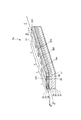
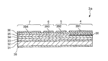
図1は、本発明のテラヘルツ波発生装置の第1実施形態を摸式的に示斜視図、図2は、図1に示すテラヘルツ波発生装置の光源装置の断面斜視図、図3は、図2中のA−A線での断面図、図4は、図2中のB−B線での断面図である。なお、図1では、一点鎖線で囲った部分を拡大して示す。
Hereinafter, a terahertz wave generation device, a camera, an imaging device, and a measurement device according to the present invention will be described in detail based on preferred embodiments shown in the accompanying drawings.
<First Embodiment>
FIG. 1 is a perspective view schematically showing a first embodiment of a terahertz wave generator according to the present invention, FIG. 2 is a cross-sectional perspective view of a light source device of the terahertz wave generator shown in FIG. 1, and FIG. 2 is a cross-sectional view taken along line AA in FIG. 2, and FIG. 4 is a cross-sectional view taken along line BB in FIG. In addition, in FIG. 1, the part enclosed with the dashed-dotted line is expanded and shown.
図1に示すように、テラヘルツ波発生装置1は、基板181と、基板181上に設置されたサブマウント基板182と、サブマウント基板182上に設置され、並設された2つの光源装置3a、3bを有し、出射のタイミング、すなわち位相の異なる2つの光パルス(パルス光)を発生する光源ユニット10と、基板181上に設置され、光源ユニット10で発生した光パルスが照射されることによりテラヘルツ波を発生するアンテナ2とを備えている。なお、各光源装置3a、3bで発生する光パルスの形状は、それぞれ、特に限定されず、1つの光パルスを見たときの形状としては、例えば、1つの波の形状、矩形等が挙げられる。また、光源装置3aにより第1の光源が構成され、光源装置3bにより第2の光源が構成される。
As shown in FIG. 1, the terahertz wave generator 1 includes a
アンテナ2は、本実施形態では、ダイポール形状光伝導アンテナ(PCA)であり、半導体基板である基板21と、基板21上に設けられ、ギャップ23を介して対向配置された1対の電極22とを有している。1対の電極22の電極間には、図示しない電圧源が接続され、その電圧源により所定の電圧が印加されており、その1対の電極22の電極間に光パルス(パルス光)が照射されると、アンテナ2は、テラヘルツ波を発生する。なお、テラヘルツ波とは、周波数が、100GHz以上30THz以下の電磁波、特に、300GHz以上3THz以下の電磁波を言う。
In this embodiment, the antenna 2 is a dipole photoconductive antenna (PCA), a
基板21の形状は、図示の構成では、平面視で四角形をなしている。なお、基板21の形状は、四角形には限定されず、この他、例えば、円形、楕円形、三角形、五角形、6角形等が挙げられる。
また、1対の電極22の電極間距離dは、特に限定されず、諸条件に応じて適宜設定されるものであるが、1μm以上10μm以下であることが好ましい。
In the illustrated configuration, the
Further, the inter-electrode distance d between the pair of
また、1対の電極22の幅wは、特に限定されず、諸条件に応じて適宜設定されるものであるが、1μm以上10μm以下であることが好ましい。
また、アンテナ2の寸法は、特に限定されず、諸条件に応じて適宜設定されるものであるが、100μm以上10mm以下×100μm以上10mm以下であることが好ましい。
また、光源ユニット10の光パルスを出射する部位とアンテナ2との間の距離Lは、特に限定されず、諸条件に応じて適宜設定されるものであるが、0.5μm以上50mm以下であることが好ましい。
Further, the width w of the pair of
The dimensions of the antenna 2 are not particularly limited, and are appropriately set according to various conditions, but are preferably 100 μm or more and 10 mm or less × 100 μm or more and 10 mm or less.
Further, the distance L between the portion of the
ここで、このテラヘルツ波発生装置1では、光源ユニット10の光源装置3a、3bから、それぞれ、共通の1対の電極22の電極間に光パルスを照射する。そして、光源ユニット10により、共通の1対の電極22の電極間に、互いにタイミング、すなわち互いに位相をずらして光パルスを照射する。これにより、1対の電極22の電極間において、光パルスの照射タイミングをずらさない場合や、光源装置3a、3bの一方からのみ光パルスを照射した場合を基準として、アンテナ2で発生するテラヘルツ波の周波数分布が変更される。すなわち、アンテナ2で発生するテラヘルツ波の周波数分布を調整することができる。
Here, in the terahertz wave generation device 1, light pulses are irradiated between the electrodes of the common pair of
なお、テラヘルツ波の周波数分布は、例えば、グラフの横軸にテラヘルツ波の周波数、縦軸にテラヘルツ波の電界強度をとった場合のそのグラフで示すことができる。この場合、例えば、1対の電極22の電極間において、光パルスの照射タイミングをずらさない場合に、テラヘルツ波の周波数分布を示す前記グラフが山型をなしているものを、光パルスの照射タイミングをずらすことにより、前記グラフが波型になるように変更することができる。
The frequency distribution of the terahertz wave can be shown, for example, in the graph when the horizontal axis of the graph is the frequency of the terahertz wave and the vertical axis is the electric field strength of the terahertz wave. In this case, for example, when the irradiation timing of the optical pulse is not shifted between the electrodes of the pair of
また、光パルスの照射タイミングのずれ量は、特に限定されず、発生するテラヘルツ波の目標の周波数分布や、諸条件に応じて適宜設定されるものであるが、光パルスのパルス幅よりも小さいことが好ましい。具体的には、光パルスの照射タイミングのずれ量は、光パルスのパルス幅の1%以上50%以下であることが好ましく、3%以上40%以下であることがより好ましい。なお、光パルスのパルス幅とは、例えば、1つの光パルスを見たときの形状が1つの波の形状である場合は、光パルスの半値幅であり、また、1つの光パルスを見たときの形状が矩形である場合は、光パルスの全幅である。 Further, the amount of deviation of the irradiation timing of the optical pulse is not particularly limited, and is appropriately set according to the target frequency distribution of the generated terahertz wave and various conditions, but is smaller than the pulse width of the optical pulse. It is preferable. Specifically, the deviation amount of the irradiation timing of the light pulse is preferably 1% or more and 50% or less of the pulse width of the light pulse, and more preferably 3% or more and 40% or less. The pulse width of the optical pulse is, for example, the half-value width of the optical pulse when the shape when one optical pulse is viewed is the shape of one wave, and when one optical pulse is viewed When the shape is rectangular, it is the full width of the light pulse.
また、光源装置3aで発生する光パルスの強度のピーク値(波高)をα1、光源装置3bで発生する1つの光パルスの強度のピーク値をα2としたとき、その比α1/α2は、特に限定されず、発生するテラヘルツ波の目標の周波数分布や、諸条件に応じて適宜設定されるものであるが、1以上10以下であることが好ましく、1以上5以下であることがより好ましい。
When the peak value (wave height) of the light pulse generated in the
なお、前記光パルスの照射タイミングのずれ量を調整すること、または、照射タイミングのずれ量およびα1/α2を調整することにより、テラヘルツ波の周波数分布を調整することができる。
これは、テラヘルツ波発生装置1に対して、予め、照射タイミングのずれ量と、テラヘルツ波の周波数分布との関係を示す演算式やテーブル等の検量線、または、照射タイミングのずれ量およびα1/α2と、テラヘルツ波の周波数分布との関係を示す演算式やテーブル等の検量線を実験的に求め、テラヘルツ波発生装置1の図示しない記憶部に記憶し、必要時にそれを読み出して使用するように構成することで実現することができる。
Note that the frequency distribution of the terahertz wave can be adjusted by adjusting the amount of deviation of the irradiation timing of the light pulse or by adjusting the amount of deviation of the irradiation timing and α1 / α2.
This is because, for the terahertz wave generator 1, a calibration curve such as an arithmetic expression or a table indicating the relationship between the irradiation timing shift amount and the terahertz wave frequency distribution, or the irradiation timing shift amount and α1 / A calibration curve such as an arithmetic expression or a table indicating the relationship between α2 and the frequency distribution of the terahertz wave is experimentally obtained, stored in a storage unit (not shown) of the terahertz wave generator 1, and read out and used when necessary. It is realizable by comprising.
次に、光源ユニット10について説明する。
光源ユニット10は、第1の光源である光源装置3aと、第2の光源である光源装置3bとを有している。光源装置3aと光源装置3bとは同様であるので、以下、代表的に、光源装置3aについて説明する。
図2〜図4に示すように、光源装置3aは、本実施形態では、光パルスを発生する光パルス発生部4と、光パルス発生部4で発生した光パルスに対し、パルス圧縮を行う第1のパルス圧縮部5と、第1のパルス圧縮部5でパルス圧縮がなされた光パルスに対し、パルス圧縮を行う第2のパルス圧縮部7と、光パルスを増幅する増幅部6とを有している。
Next, the
The
As shown in FIGS. 2 to 4, in the present embodiment, the
増幅部6は、第1のパルス圧縮部5の前段、または第1のパルス圧縮部5と第2のパルス圧縮部7との間に設けられるが、図示の構成では、増幅部6は、第1のパルス圧縮部5と第2のパルス圧縮部7との間に設けられている。これにより、第1のパルス圧縮部5でパルス圧縮がなされた光パルスが、増幅部6で増幅され、増幅部6で増幅された光パルスが、第2のパルス圧縮部7でパルス圧縮がなされる。
The amplifying
また、光源装置3aから出射する光パルスのパルス幅(半値幅)は、特に限定されないが、10f秒以上800f秒以下であることが好ましい。
また、光パルス発生部4は、例えば、DBRレーザー、DFBレーザー、モード同期レーザー等、いわゆる半導体レーザーを用いることができる。この光パルス発生部4で発生する光パルスのパルス幅は、特に限定されないが、1p秒以上100p秒以下であることが好ましい。
The pulse width (half width) of the light pulse emitted from the
The optical pulse generator 4 may be a so-called semiconductor laser such as a DBR laser, a DFB laser, or a mode-locked laser. The pulse width of the optical pulse generated by the optical pulse generator 4 is not particularly limited, but is preferably 1 psec or more and 100 psec or less.
また、第1のパルス圧縮部5は、可飽和吸収に基づくパルス圧縮を行うものである。すなわち、第1のパルス圧縮部5は、可飽和吸収体を有しており、その可飽和吸収体により、光パルスを圧縮し、そのパルス幅を減少させる。
また、第2のパルス圧縮部7は、群速度分散補償に基づくパルス圧縮を行うものである。すなわち、第2のパルス圧縮部7は、群速度分散補償媒体、本実施形態では、結合導波路構造を有しており、その結合導波路構造により、光パルスを圧縮し、そのパルス幅を減少させる。
The first
The second
また、光源装置3aの光パルス発生部4と、第1のパルス圧縮部5と、増幅部6と、第2のパルス圧縮部7とは、一体化、すなわち同一基板上に集積されている。
具体的には、光源装置3aは、半導体基板である基板31と、基板31上に設けられたクラッド層32と、クラッド層32上に設けられた活性層33と、活性層33上に設けられた導波路構成プロセス用エッチングストップ層34と、導波路構成プロセス用エッチングストップ層34上に設けられたクラッド層35と、クラッド層35上に設けられたコンタクト層36と、導波路構成プロセス用エッチングストップ層34上に設けられた絶縁層37と、基板31の表面に設けられたクラッド層32側の電極38と、コンタクト層36および絶縁層37の表面に設けられたクラッド層35側の電極391、392、393、394および395とを有している。また、光パルス発生部4の導波路構成プロセス用エッチングストップ層34と、クラッド層35との間には、回折格子30が設けられている。なお、導波路構成プロセス用エッチングストップ層は、活性層の直上に限らず、例えば、クラッド層の中に設けられていてもよい。
In addition, the optical pulse generation unit 4, the first
Specifically, the
なお、各部の構成材料は、特に限定されないが、一例として、基板31、コンタクト層36としては、それぞれ、例えば、GaAs等が挙げられる。また、クラッド層32、35、導波路構成プロセス用エッチングストップ層34、回折格子30としては、それぞれ、例えば、AlGaAs等が挙げられる。また、活性層33としては、例えば、多重量子井戸と呼ばれる量子効果を用いた構成等が挙げられる。具体的には、活性層33としては、例えば、井戸層(GaAs井戸層)とバリア層(AlGaAsバリア層)とを交互に複数ずつ設けてなる多重量子井戸等で構成された分布屈折率型多重量子井戸と呼ばれる称される構造のもの等が挙げられる。
In addition, although the constituent material of each part is not specifically limited, As an example, as the board |
また、図示の構成では、光源装置3aにおける導波路は、クラッド層32と、活性層33と、導波路構成プロセス用エッチングストップ層34と、クラッド層35とで構成されている。また、クラッド層35は、導波路の上部にのみ、その導波路に対応した形状に設けられている。また、クラッド層35は、不要な部分をエッチングにより除去することにより形成されている。なお、製造方法によっては、導波路構成プロセス用エッチングストップ層34を省略してもよい。
In the configuration shown in the figure, the waveguide in the
また、クラッド層35およびコンタクト層36は、それぞれ、2つずつ設けられている。一方のクラッド層35およびコンタクト層36は、光パルス発生部4と、第1のパルス圧縮部5と、増幅部6と、第2のパルス圧縮部7の一部を構成し、連続的に設けられており、他方のクラッド層35およびコンタクト層36は、第2のパルス圧縮部7の一部を構成している。すなわち、第2のパルス圧縮部7には、1対のクラッド層35と、1対のコンタクト層36とが設けられている。
Two
また、電極391は、光パルス発生部4のクラッド層35に対応するように設けられ、また、電極392は、第1のパルス圧縮部5のクラッド層35に対応するように設けられ、また、電極393は、増幅部6のクラッド層35に対応するように設けられ、また、電極394および395は、それぞれ、第2のパルス圧縮部7の2つのクラッド層35に対応するように設けられている。なお、電極38は、光パルス発生部4、第1のパルス圧縮部5、増幅部6および第2のパルス圧縮部7の共通の電極である。そして、電極38と電極391とで光パルス発生部4の1対の電極が構成され、また、電極38と電極392とで第1のパルス圧縮部5の1対の電極が構成され、また、電極38と電極393とで増幅部6の1対の電極が構成され、また、電極38と電極394、電極38と電極395とで第2のパルス圧縮部7の2対の電極が構成される。
なお、光源装置3aの全体形状は、図示の構成では、直方体をなしているが、これに限定されないことは、言うまでもない。
また、光源装置3aの寸法は、特に限定されないが、例えば、1mm以上10mm以下×0.5mm以上5mm以下×0.1mm以上1mm以下とすることができる。
In addition, the
In addition, although the whole shape of the
Moreover, although the dimension of the
次に、テラヘルツ波発生装置1の作用について説明する。
テラヘルツ波発生装置1では、まず、光源ユニット10の光源装置3a、3bの光パルス発生部4で、それぞれ、光パルスを発生する。以下、代表的に1つの光源装置3aについて説明する。光パルス発生部4で発生した光パルスのパルス幅は、目標のパルス幅に比べて大きい。その光パルス発生部4で発生した光パルスは、導波路を通り、第1のパルス圧縮部5、増幅部6、第2のパルス圧縮部7をこの順序で順次通過する。
Next, the operation of the terahertz wave generator 1 will be described.
In the terahertz wave generation device 1, first, light pulses are generated by the light pulse generation units 4 of the
まず、第1のパルス圧縮部5で、光パルスに対し、可飽和吸収に基づくパルス圧縮がなされ、光パルスのパルス幅が減少する。次に、増幅部6で、光パルスが増幅される。最後に、第2のパルス圧縮部7で、光パルスに対し、群速度分散補償に基づくパルス圧縮がなされ、光パルスのパルス幅がさらに減少する。このようにして、目標のパルス幅の光パルスが発生し、第2のパルス圧縮部7から出射する。この場合、光源装置3a、3bからは、互いにタイミング(位相)をずらして光パルスを出射する。
First, in the first
光源装置3a、3bから出射した光パルスは、それぞれ、アンテナ2の1対の電極22の電極間に、互いにタイミング(位相)をずらして照射され、そのアンテナ2で、テラヘルツ波が発生する。前述したように、光パルスの照射タイミングのずれ量を調整することにより、テラヘルツ波の周波数分布を調整することができる。
以上説明したように、このテラヘルツ波発生装置1によれば、容易かつ確実に、テラヘルツ波の周波数分布を調整することができる。
The light pulses emitted from the
As described above, according to the terahertz wave generator 1, the frequency distribution of the terahertz wave can be adjusted easily and reliably.
また、各光源装置3a、3bが第1のパルス圧縮部5、増幅部6および第2のパルス圧縮部7を有しているので、光源装置3a、3bの小型化、ひいてはテラヘルツ波発生装置1の小型化を図りつつ、所望の波高で、かつ所望のパルス幅の光パルスを発生することができ、これにより、所望のテラヘルツ波を確実に発生することができる。また、光源装置3a、3bの駆動信号のタイミングを変えことにより、容易に光源装置3a、3bの発光タイミングを変えてアンテナ2に照射することができる。すなわち、アンテナ2に照射する光パルスのタイミングを変えるために遅延素子などの追加構成を設ける必要がなく、簡易な構成とすることができる。
なお、光源ユニット10の光源装置の数は、2つには限定されず、3つ以上であってもよい。
また、アンテナ2の1対の電極22の数は、1つには限定されず、2つ以上であってもよい。
Moreover, since each
The number of light source devices of the
Further, the number of the pair of
<第2実施形態>
図5は、本発明のテラヘルツ波発生装置の第2実施形態を摸式的に示す斜視図、図6は、図5に示すテラヘルツ波発生装置の光源装置の断面斜視図である。なお、図5では、単位ユニット8a、8bの互いの境界を破線で示す。
以下、第2実施形態について、前述した第1実施形態との相違点を中心に説明し、同様の事項については、その説明を省略する。
Second Embodiment
FIG. 5 is a perspective view schematically showing a second embodiment of the terahertz wave generator of the present invention, and FIG. 6 is a cross-sectional perspective view of the light source device of the terahertz wave generator shown in FIG. In FIG. 5, the boundary between the
Hereinafter, the second embodiment will be described with a focus on the differences from the first embodiment described above, and the description of the same matters will be omitted.
図5および図6に示すように、第2実施形態のテラヘルツ波発生装置1では、光源ユニット10は、光パルス発生部4と、第1のパルス圧縮部5と、増幅部6と、第2のパルス圧縮部7とを有する第1の光源である単位ユニット8aと、第2の光源である単位ユニット8bとを備えており、これらの単位ユニット8a、8bが並設され、一体化、すなわちアレイ化されている。これにより、光源ユニット10の小型化を図ることができ、これによって、テラヘルツ波発生装置1の小型化を図ることができる。なお、各単位ユニット8a、8bは、それぞれ、前記第1実施形態における光源装置3a、3bに対応している。
なお、この第2実施形態は、後述する第4実施形態、第5実施形態および第6実施形態にも適用することができる。
As shown in FIGS. 5 and 6, in the terahertz wave generation device 1 of the second embodiment, the
Note that the second embodiment can also be applied to a fourth embodiment, a fifth embodiment, and a sixth embodiment described later.
<第3実施形態>
図7は、本発明のテラヘルツ波発生装置の第3実施形態を摸式的に示す斜視図である。なお、図7では、単位ユニット8a、8b、8c、8dの互いの境界を破線で示す。
以下、第3実施形態について、前述した実施形態との相違点を中心に説明し、同様の事項については、その説明を省略する。
<Third Embodiment>
FIG. 7 is a perspective view schematically showing a third embodiment of the terahertz wave generator of the present invention. In FIG. 7, the boundaries of the
Hereinafter, the third embodiment will be described with a focus on differences from the above-described embodiment, and description of similar matters will be omitted.
図7に示すように第2実施形態のテラヘルツ波発生装置1では、光源ユニット10は、第1の光源である単位ユニット8aと、第2の光源である単位ユニット8bと、第3の光源である単位ユニット8cと、第4の光源である単位ユニット8dとを備えており、これらの単位ユニット8a、8b、8c、8dが一体化、すなわちアレイ化されている。これにより、光源ユニット10の小型化を図ることができ、これによって、テラヘルツ波発生装置1の小型化を図ることができる。なお、各単位ユニット8a、8bは、それぞれ、前記第2実施形態における単位ユニット8a、8bに対応し、また、各単位ユニット8c、8dは、それぞれ、単位ユニット8a、8bと同様のものである。また、単位ユニット8a、8bは、並設され、単位ユニット8c、8dは、それぞれ、単位ユニット8a、8bの下方に位置し、並設されている。
As shown in FIG. 7, in the terahertz wave generation device 1 of the second embodiment, the
アンテナ2は、半導体基板である基板21と、基板21上に設けられ、ギャップ23を介して対向配置された第1の1対の電極である1対の電極22aと、ギャップ23を介して対向配置された第2の1対の電極である1対の電極22bとを有している。1対の電極22aの電極間、1対の電極22bの電極間には、それそれ、所定の電圧が印加されており、その1対の電極22aの電極間、1対の電極22bの電極間に光パルスが照射されると、アンテナ2は、テラヘルツ波を発生する。
The antenna 2 is opposed to a
この場合、本実施形態では、1対の電極22a、1対の電極22bのうち一方の側同士、すなわち一方の側の電極22a、22b同士が導電体24で電気的に接続されており、他方の側同士、すなわち他方の側の電極22a、22b同士が導電体24で電気的に接続されている。そして、その一方の側同士、すなわち一方の側の電極22a、22b同士、または他方の側同士、すなわち他方の側の電極22a、22b同士には、同一の電圧が印加される。すなわち、一方の側の電極22a、22bと、他方の側の電極22a、22bとの間に、図示しない電圧源が接続され、その電圧源により所定の電圧が印加されている。なお、1対の電極22aの電極間、1対の電極22bの電極間のそれぞれに個別に電圧源を接続し、各電極間に個別に電圧を印加してもよい。
また、電極22a、22bのピッチpは、特に限定されず、諸条件に応じて適宜設定されるものであるが、10μm以上1mm以下であることが好ましい。
In this case, in this embodiment, one side of the pair of
Further, the pitch p of the
ここで、このテラヘルツ波発生装置1では、光源ユニット10の単位ユニット8a、8bから、それぞれ、共通の1対の電極22aの電極間に光パルスを照射する。そして、光源ユニット10により、共通の1対の電極22aの電極間に、互いにタイミング、すなわち互いに位相をずらして光パルスを照射する。これにより、1対の電極22aの電極間において、光パルスの照射タイミングをずらさない場合や、単位ユニット8a、8bの一方からのみ光パルスを照射した場合を基準として、アンテナ2で発生するテラヘルツ波の周波数分布が変更される。すなわち、アンテナ2で発生するテラヘルツ波の周波数分布を調整することができる。
Here, in the terahertz wave generation device 1, a light pulse is irradiated between the electrodes of the common pair of
同様に、光源ユニット10の単位ユニット8c、8dから、それぞれ、共通の1対の電極22bの電極間に光パルスを照射する。そして、光源ユニット10により、共通の1対の電極22bの電極間に、互いにタイミング、すなわち互いに位相をずらして光パルスを照射する。これにより、1対の電極22bの電極間において、光パルスの照射タイミングをずらさない場合や、単位ユニット8c、8dの一方からのみ光パルスを照射した場合を基準として、アンテナ2で発生するテラヘルツ波の周波数分布が変更される。すなわち、アンテナ2で発生するテラヘルツ波の周波数分布を調整することができる。
Similarly, a light pulse is irradiated between the electrodes of the common pair of
なお、1対の電極22aの電極間における光パルスの照射タイミングのずれ量、1対の電極22bの電極間における光パルスの照射タイミングのずれ量を調整すること、または、1対の電極22aの電極間における光パルスの照射タイミングのずれ量、1対の電極22bの電極間における光パルスの照射タイミングのずれ量、各α1/α2を調整することにより、テラヘルツ波の周波数分布を調整することができる。
It should be noted that the amount of deviation of the irradiation timing of the light pulse between the electrodes of the pair of
これは、テラヘルツ波発生装置1に対して、予め、各照射タイミングのずれ量と、テラヘルツ波の周波数分布との関係を示す演算式やテーブル等の検量線、または、各照射タイミングのずれ量および各α1/α2と、テラヘルツ波の周波数分布との関係を示す演算式やテーブル等の検量線を実験的に求め、テラヘルツ波発生装置1の図示しない記憶部に記憶し、必要時にそれを読み出して使用するように構成することで実現することができる。 This is because, with respect to the terahertz wave generator 1, a calibration curve such as an arithmetic expression or a table indicating the relationship between the deviation amount of each irradiation timing and the frequency distribution of the terahertz wave, or the deviation amount of each irradiation timing and A calibration curve such as an arithmetic expression or a table indicating the relationship between each α1 / α2 and the frequency distribution of the terahertz wave is experimentally obtained, stored in a storage unit (not shown) of the terahertz wave generator 1, and read out when necessary. It can be realized by configuring to use.
また、このテラヘルツ波発生装置1では、光源ユニット10により、1対の電極22aの電極間と、1対の電極22bの電極間とに、互いにタイミング、すなわち互いに位相をずらして光パルスを照射する。すなわち、単位ユニット8aから発せられる光パルスと単位ユニット8bから発せられる光パルスとの少なくとも一方と、単位ユニット8cから発せられる光パルスと単位ユニット8dから発せられる光パルスとの少なくとも一方との位相が異なる。本実施形態では、単位ユニット8aから発せられる光パルスと単位ユニット8cから発せられる光パルスとの位相が異なり、また、単位ユニット8bから発せられる光パルスと単位ユニット8dから発せられる光パルスとの位相が異なる。これにより、1対の電極22aの電極間と、1対の電極22bの電極間とにおいて、互いに位相の異なるテラヘルツ波が発生し、それらのテラヘルツ波が合成され、前記光パルスの照射タイミングをずらさない場合を基準として、アンテナ2で発生するテラヘルツ波の出射方向が変更される。すなわち、アンテナ2で発生するテラヘルツ波の出射方向を調整することができる。
Further, in this terahertz wave generating device 1, the
また、単位ユニット8aから発せられ、1対の電極22aの電極間に照射される光パルスと、単位ユニット8cから発せられ、1対の電極22bの電極間に照射される光パルスとのずれ量、単位ユニット8bから発せられ、1対の電極22aの電極間に照射される光パルスと、単位ユニット8dから発せられ、1対の電極22bの電極間に照射される光パルスとのずれ量は、それぞれ、特に限定されず、発生するテラヘルツ波の目標の出射方向や、諸条件に応じて適宜設定されるものであるが、光パルスのパルス幅よりも小さいことが好ましい。具体的には、光パルスの照射タイミングのずれ量は、光パルスのパルス幅の1%以上50%以下であることが好ましく、3%以上40%以下であることがより好ましい。
Further, the amount of deviation between the light pulse emitted from the
なお、1対の電極22aの電極間と1対の電極22bの電極間とにおける光パルスの照射タイミングのずれ量を調整することにより、テラヘルツ波の出射方向を調整することができる。
これは、テラヘルツ波発生装置1に対して、予め、照射タイミングのずれ量と、テラヘルツ波の出射方向との関係を示す演算式やテーブル等の検量線を実験的に求め、テラヘルツ波発生装置1の図示しない記憶部に記憶し、必要時にそれを読み出して使用するように構成することで実現することができる。
Note that the emission direction of the terahertz wave can be adjusted by adjusting the amount of light pulse irradiation timing between the pair of
This is because the terahertz wave generator 1 is experimentally determined in advance to obtain a calibration curve such as an arithmetic expression or a table indicating the relationship between the amount of deviation in irradiation timing and the emission direction of the terahertz wave. This can be realized by storing in a storage unit (not shown), and reading and using it when necessary.
以上説明したように、このテラヘルツ波発生装置1によれば、テラヘルツ波の周波数分布を調整することができ、また、テラヘルツ波の出射方向を変更することができる。
なお、光源ユニット10の単位ユニット(光源装置)の数は、4つには限定されず、5つ以上であってもよい。
また、アンテナ2の1対の電極22の数は、2つには限定されず、3つ以上であってもよい。
なお、この第3実施形態は、後述する第4実施形態、第5実施形態および第6実施形態にも適用することができる。
As described above, according to the terahertz wave generator 1, the frequency distribution of the terahertz wave can be adjusted, and the emission direction of the terahertz wave can be changed.
The number of unit units (light source devices) of the
Further, the number of the pair of
This third embodiment can also be applied to a fourth embodiment, a fifth embodiment, and a sixth embodiment which will be described later.
<第4実施形態>
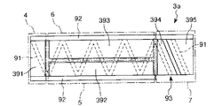
図8は、本発明のテラヘルツ波発生装置の第4実施形態における光源装置を摸式的に示す平面図である。なお、図8では、導波路91を破線で示し、また、第1のパルス圧縮部5、増幅部6および第2のパルス圧縮部7をそれぞれ破線で囲って示す。
以下、第4実施形態について、前述した実施形態との相違点を中心に説明し、同様の事項については、その説明を省略する。
<Fourth embodiment>
FIG. 8 is a plan view schematically showing a light source device in the fourth embodiment of the terahertz wave generation device of the present invention. In FIG. 8, the
Hereinafter, the fourth embodiment will be described with a focus on differences from the above-described embodiment, and description of similar matters will be omitted.
図8に示すように、第4実施形態のテラヘルツ波発生装置1の光源装置3aでは、導波路91が複数回、交互に折り曲げられている。すなわち、導波路91は、ジグザグに形成されている。
また、第1のパルス圧縮部5は、図8中下側に位置し、また、増幅部6は、図8中上側に位置している。そして、第1のパルス圧縮部5および増幅部6において、それぞれ導波路91が複数回折り曲げられている。また、光パルス発生部4と第1のパルス圧縮部5との境界部、増幅部6と第2のパルス圧縮部7との境界部において、それぞれ導波路91が1回折り曲げられている。
As shown in FIG. 8, in the
The first
また、光源装置3aは、導波路91の折り曲げ部分に、光パルスを反射させる反射膜92を有している。この反射膜92は、光源装置の1対の側面に、それぞれ設けられている。この反射膜92により、光パルスが導波路91に沿って進むようにその光パルスを反射させることができる。
なお、光源装置3aの光パルスの出射部93には、反射膜92は設けられていない。また、出射部93には、反射防止膜(図示せず)を設けてもよい。
このテラヘルツ波発生装置1によれば、光源装置3aの導波路91が複数回折り曲げられているので、光路長、すなわち、導波路91の直線距離を長くすることができ、これにより、光源装置3aの長さを短くすることができ、さらに小型化を図ることができる。
Further, the
Note that the
According to the terahertz wave generating device 1, since the
<第5実施形態>
図9は、本発明のテラヘルツ波発生装置の第5実施形態における光源装置を模式的に示す平面図である。なお、図9では、導波路を破線で示し、また、第1のパルス圧縮部5、増幅部6および第2のパルス圧縮部7をそれぞれ破線で囲って示す。
<Fifth Embodiment>
FIG. 9 is a plan view schematically showing a light source device in the fifth embodiment of the terahertz wave generation device of the present invention. In FIG. 9, the waveguide is indicated by a broken line, and the first
以下、第5実施形態について、前述した実施形態との相違点を中心に説明し、同様の事項については、その説明を省略する。
図9に示すように、第4実施形態のテラヘルツ波発生装置1の光源装置3aでは、導波路91が3回、交互に折り曲げられており、増幅部6においては、導波路91は、1回だけ折り曲げられている。
なお、増幅部6を第1のパルス圧縮部5の前段に設ける場合は、第1のパルス圧縮部5において、導波路91は、1回だけ折り曲げられる。
Hereinafter, the fifth embodiment will be described with a focus on differences from the above-described embodiments, and description of similar matters will be omitted.
As shown in FIG. 9, in the
When the
<第6実施形態>
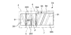
図10は、本発明のテラヘルツ波発生装置の第6実施形態における光源装置を摸式的に示す平面図である。なお、図10では、導波路を破線で示し、また、第1のパルス圧縮部5、増幅部6および第2のパルス圧縮部7をそれぞれ破線で囲って示す。
以下、第6実施形態について、前述した実施形態との相違点を中心に説明し、同様の事項については、その説明を省略する。
<Sixth Embodiment>
FIG. 10 is a plan view schematically showing a light source device in the sixth embodiment of the terahertz wave generation device of the present invention. In FIG. 10, the waveguide is indicated by a broken line, and the first
Hereinafter, the sixth embodiment will be described with a focus on differences from the above-described embodiment, and description of similar matters will be omitted.
図10に示すように、第6実施形態のテラヘルツ波発生装置1の光源装置3aでは、反射膜92は省略されている。
また、導波路91の折り曲げ部分における図10に示す角度θは、臨界角以上に設定されている。これにより、導波路91の折り曲げ部分に反射膜92を設けることなく、光パルスを反射させることができ、構造を簡素化することができる。
また、光源装置3aの光パルスの出射部93に反射防止膜94が設けられている。これにより、出射部93から光パルスを出射させることができる。
なお、この第6実施形態は、前記第4実施形態にも適用することができる。
As shown in FIG. 10, the
Further, the angle θ shown in FIG. 10 at the bent portion of the
Further, an
The sixth embodiment can also be applied to the fourth embodiment.
<イメージング装置の実施形態>
図11は、本発明のイメージング装置の実施形態を示すブロック図である。図12は、図11に示すイメージング装置のテラヘルツ波検出装置を示す平面図である。
図11に示すように、イメージング装置100は、テラヘルツ波を発生するテラヘルツ波発生装置1と、テラヘルツ波発生装置1から出射し、対象物150を透過または反射したテラヘルツ波を検出するテラヘルツ波検出装置11と、テラヘルツ波検出装置11の検出結果に基づいて、対象物150の画像、すなわち、画像データを生成する画像形成部12とを備えている。
<Embodiment of Imaging Apparatus>
FIG. 11 is a block diagram showing an embodiment of the imaging apparatus of the present invention. 12 is a plan view showing a terahertz wave detecting device of the imaging apparatus shown in FIG.
As illustrated in FIG. 11, an
テラヘルツ波発生装置1としては、本実施形態では、前記第1実施形態〜第6実施形態のうちのいずれかのものを用いる。
また、テラヘルツ波検出装置11としては、例えば、目的の波長のテラヘルツ波を通過させるフィルター15と、フィルター15を通過した前記目的の波長のテラヘルツ波を熱に変換して検出する検出部17とを備えたものを用いる。また、検出部17としては、例えば、テラヘルツ波を熱に変換して検出するもの、すなわち、テラヘルツ波を熱に変換し、そのテラヘルツ波のエネルギー(強度)を検出し得るものを用いる。このような検出部としては、例えば、焦電センサー、ボロメーター等が挙げられる。なお、テラヘルツ波検出装置11としては、前記の構成のものに限定されないことは、言うまでもない。
As the terahertz wave generating device 1, any one of the first to sixth embodiments is used in the present embodiment.
The terahertz
また、フィルター15は、2次元的に配置された複数の画素(単位フィルター部)16を有している。すなわち、各画素16は、行列状に配置されている。
また、各画素16は、互いに異なる波長のテラヘルツ波を通過させる複数の領域、すなわち、通過させるテラヘルツ波の波長(以下、「通過波長」とも言う)が互いに異なる複数の領域を有している。なお、図示の構成では、各画素16は、第1の領域161、第2の領域162、第3の領域163および第4の領域164を有している。
The
Each
また、検出部17は、フィルター15の各画素16の第1の領域161、第2の領域162、第3の領域163および第4の領域164に対応してそれぞれ設けられた第1の単位検出部171、第2の単位検出部172、第3の単位検出部173および第4の単位検出部174を有している。各第1の単位検出部171、各第2の単位検出部172、各第3の単位検出部173および各第4の単位検出部174は、それぞれ、各画素16の第1の領域161、第2の領域162、第3の領域163および第4の領域164を通過したテラヘルツ波を熱に変換して検出する。これにより、各画素16のそれぞれにおいて、4つの目的の波長のテラヘルツ波をそれぞれ確実に検出することができる。
The
次に、イメージング装置100の使用例について説明する。
まず、分光イメージングの対象となる対象物150は、3つの物質A、BおよびCで構成されている。イメージング装置100は、この対象物150の分光イメージングを行う。また、ここでは、一例として、テラヘルツ波検出装置11は、対象物150を反射したテラヘルツ波を検出することとする。
Next, a usage example of the
First, an
図13は、対象物150のテラヘルツ帯でのスペクトルを示すグラフである。
テラヘルツ波検出装置11のフィルター15の各画素16においては、第1の領域161および第2の領域162を使用する。
また、第1の領域161の通過波長をλ1、第2の領域162の通過波長をλ2とし、対象物150で反射したテラヘルツ波の波長λ1の成分の強度をα1、波長λ2の成分の強度をα2としたとき、その強度α2と強度α1の差分(α2−α1)が、物質Aと物質Bと物質Cとで、互いに顕著に区別できるように、前記第1の領域161の通過波長λ1および第2の領域162の通過波長λ2が設定されている。
FIG. 13 is a graph showing a spectrum of the
In each
Further, the transmission wavelength of the
図13に示すように、物質Aにおいては、対象物150で反射したテラヘルツ波の波長λ2の成分の強度α2と波長λ1の成分の強度α1の差分(α2−α1)は、正値となる。
また、物質Bにおいては、強度α2と強度α1の差分(α2−α1)は、零となる。
また、物質Cにおいては、強度α2と強度α1の差分(α2−α1)は、負値となる。
As shown in FIG. 13, in the substance A, the difference (α2−α1) between the intensity α2 of the component of wavelength λ2 of the terahertz wave reflected by the
In the substance B, the difference (α2−α1) between the intensity α2 and the intensity α1 is zero.
Further, in the substance C, the difference (α2−α1) between the intensity α2 and the intensity α1 is a negative value.
イメージング装置100により、対象物150の分光イメージングを行う際は、まず、テラヘルツ波発生装置1により、テラヘルツ波を発生し、そのテラヘルツ波を対象物150に照射する。そして、対象物150で反射したテラヘルツ波をテラヘルツ波検出装置11で、α1およびα2として検出する。この検出結果は、画像形成部12に送出される。なお、この対象物150へのテラヘルツ波の照射および対象物150で反射したテラヘルツ波の検出は、対象物150の全体に対して行う。この場合、前記対象物150へのテラヘルツ波の照射は、光源ユニット10により、各1対の電極22間に、互いにタイミングをずらして光パルスを照射し、その光パルスの照射タイミングのずれ量を変更することにより、テラヘルツ波の出射方向を変更して行う。
When spectral imaging of the
画像形成部12においては、前記検出結果に基づいて、フィルター15の第2の領域162を通過したテラヘルツ波の波長λ2の成分の強度α2と、第1の領域161を通過したテラヘルツ波の波長λ1の成分の強度α1の差分(α2−α1)を求める。そして、対象物150のうち、前記差分が正値となる部位を物質A、前記差分が零となる部位を物質B、前記差分が負値となる部位を物質Cと判断し、特定する。
In the
また、画像形成部12では、図14に示すように、対象物150の物質A、BおよびCの分布を示す画像の画像データを作成する。この画像データは、画像形成部12から図示しないモニターに送出され、そのモニターにおいて、対象物150の物質A、BおよびCの分布を示す画像が表示される。この場合、例えば、対象物150の物質Aの分布する領域は黒色、物質Bの分布する領域は灰色、物質Cの分布する領域は白色に色分けして表示される。このイメージング装置100では、以上のように、対象物150を構成する各物質の同定と、その各部質の分布測定とを同時に行うことができる。
なお、イメージング装置100の用途は、前記のものに限らず、例えば、人物に対してテラヘルツ波を照射し、その人物を透過または反射したテラヘルツ波を検出し、画像形成部12において処理を行うことにより、その人物が、拳銃、ナイフ、違法な薬物等を所持しているか否かを判別することもできる。
Further, as shown in FIG. 14, the
The application of the
<計測装置の実施形態>
図15は、本発明の計測装置の実施形態を示すブロック図である。
以下、計測装置の実施形態について、前述したイメージング装置の実施形態との相違点を中心に説明し、同様の事項については、その説明を省略する。
図15に示すように、計測装置200は、テラヘルツ波を発生するテラヘルツ波発生装置1と、テラヘルツ波発生装置1から出射し、対象物160を透過または反射したテラヘルツ波を検出するテラヘルツ波検出装置11と、テラヘルツ波検出装置11の検出結果に基づいて、対象物160を計測する計測部13とを備えている。
<Embodiment of measuring device>
FIG. 15 is a block diagram showing an embodiment of the measuring apparatus of the present invention.
Hereinafter, the embodiment of the measurement apparatus will be described focusing on the differences from the above-described embodiment of the imaging apparatus, and the description of the same matters will be omitted.
As shown in FIG. 15, the measuring
次に、計測装置200の使用例について説明する。
計測装置200により、対象物160の分光計測を行う際は、まず、テラヘルツ波発生装置1により、テラヘルツ波を発生し、そのテラヘルツ波を対象物160に照射する。そして、対象物160を透過または反射したテラヘルツ波をテラヘルツ波検出装置11で検出する。この検出結果は、計測部13に送出される。なお、この対象物160へのテラヘルツ波の照射および対象物160を透過または反射したテラヘルツ波の検出は、対象物160の全体に対して行う。この場合、前記対象物160へのテラヘルツ波の照射は、光源ユニット10により、各1対の電極22間に、互いにタイミングをずらして光パルスを照射し、その光パルスの照射タイミングのずれ量を変更することにより、テラヘルツ波の出射方向を変更して行う。
計測部13においては、前記検出結果から、フィルター15の第1の領域161、第2の領域162、第3の領域163および第4の領域164を通過したテラヘルツ波のそれぞれの強度を把握し、対象物160の成分およびその分布の分析等を行う。
Next, a usage example of the measuring
When performing spectroscopic measurement of the
In the
<カメラの実施形態>
図16は、本発明のカメラの実施形態を示すブロック図である。
以下、カメラの実施形態について、前述したイメージング装置の実施形態との相違点を中心に説明し、同様の事項については、その説明を省略する。
図16に示すように、カメラ300は、テラヘルツ波を発生するテラヘルツ波発生装置1と、テラヘルツ波発生装置1から出射し、対象物170を透過または反射したテラヘルツ波を検出するテラヘルツ波検出装置11とを備えている。
<Embodiment of Camera>
FIG. 16 is a block diagram showing an embodiment of the camera of the present invention.
Hereinafter, the embodiment of the camera will be described focusing on the differences from the above-described embodiment of the imaging apparatus, and the description of the same matters will be omitted.
As illustrated in FIG. 16, the
次に、カメラ300の使用例について説明する。
カメラ300により、対象物170を撮像する際は、まず、テラヘルツ波発生装置1により、テラヘルツ波を発生し、そのテラヘルツ波を対象物170に照射する。そして、対象物170を透過または反射したテラヘルツ波をテラヘルツ波検出装置11で検出する。この検出結果は、記憶部14に送出され、記憶される。なお、この対象物170へのテラヘルツ波の照射および対象物170を透過または反射したテラヘルツ波の検出は、対象物170の全体に対して行う。この場合、前記対象物170へのテラヘルツ波の照射は、光源ユニット10により、各1対の電極22間に、互いにタイミングをずらして光パルスを照射し、その光パルスの照射タイミングのずれ量を変更することにより、テラヘルツ波の出射方向を変更して行う。また、前記検出結果は、例えば、パーソナルコンピューター等の外部装置に送信することもできる。パーソナルコンピューターでは、前記検出結果に基づいて、各処理を行うことができる。
Next, a usage example of the
When the
以上、本発明のテラヘルツ波発生装置、カメラ、イメージング装置および計測装置を、図示の実施形態に基づいて説明したが、本発明はこれに限定されるものではなく、各部の構成は、同様の機能を有する任意の構成のものに置換することができる。また、本発明に、他の任意の構成物が付加されていてもよい。
また、本発明は、前記各実施形態のうちの、任意の2以上の構成(特徴)を組み合わせたものであってもよい。
なお、本発明では、光源装置(光源ユニット)において、光パルス発生部が別体になっていてもよい。
The terahertz wave generation device, camera, imaging device, and measurement device of the present invention have been described based on the illustrated embodiment. However, the present invention is not limited to this, and the configuration of each unit has the same function. Can be replaced with any structure having In addition, any other component may be added to the present invention.
Further, the present invention may be a combination of any two or more configurations (features) of the above embodiments.
In the present invention, in the light source device (light source unit), the light pulse generator may be a separate body.
1…テラヘルツ波発生装置 2…アンテナ 21…基板 22、22a、22b…電極 23…ギャップ 24…導電体 3a、3b…光源装置 30…回折格子 31…基板 32、35…クラッド層 33…活性層 34…導波路構成プロセス用エッチングストップ層 36…コンタクト層 37…絶縁層 38、391〜395…電極 4…光パルス発生部 5…第1のパルス圧縮部 6…増幅部 7…第2のパルス圧縮部 8a、8b、8c、8d…単位ユニット 91…導波路 92…反射膜 93…出射部 94…反射防止膜 10…光源ユニット 11…テラヘルツ波検出装置 12…画像形成部 13…計測部 14…記憶部 15…フィルター 16…画素 161…第1の領域 162…第2の領域 163…第3の領域 164…第4の領域 17…検出部 171…第1の単位検出部 172…第2の単位検出部 173…第3の単位検出部 174…第4の単位検出部 181…基板 182…サブマウント基板 100…イメージング装置 150、160、170…対象物 200…計測装置 300…カメラ
DESCRIPTION OF SYMBOLS 1 ... Terahertz wave generator 2 ...
Claims (13)
前記第1の光源および前記第2の光源にて発生したパルス光が照射されることによりテラヘルツ波を発生するアンテナとを備え、
前記第1の光源および前記第2の光源は、
光パルスを発生する光パルス発生部と、
前記光パルス発生部で発生した光パルスに対しパルス圧縮を行うパルス圧縮部と、をそれぞれ有し、
前記アンテナは、ギャップを介して対向配置された1対の電極を有しており、
前記第1の光源および前記第2の光源には、それぞれ異なる駆動信号が入力され、
前記第1の光源および前記第2の光源は、前記1対の電極間に、互いにタイミングをずらしてパルス光を照射するよう構成されていることを特徴とするテラヘルツ波発生装置。 A first light source and a second light source for generating pulsed light;
An antenna that generates terahertz waves by being irradiated with pulsed light generated by the first light source and the second light source,
The first light source and the second light source are:
An optical pulse generator for generating optical pulses;
A pulse compression unit that performs pulse compression on the optical pulse generated by the optical pulse generation unit,
The antenna has a pair of electrodes opposed to each other through a gap,
Different drive signals are input to the first light source and the second light source ,
The terahertz wave generator according to claim 1, wherein the first light source and the second light source are configured to irradiate pulsed light between the pair of electrodes at different timings.
前記第1の光源、前記第2の光源、前記第3の光源および前記第4の光源にて発生したパルス光が照射されることによりテラヘルツ波を発生するアンテナとを備え、
前記第1の光源、前記第2の光源、前記第3の光源および前記第4の光源は、
光パルスを発生する光パルス発生部と、
前記光パルス発生部で発生した光パルスに対しパルス圧縮を行うパルス圧縮部と、をそれぞれ有し、
前記アンテナは、ギャップを介して対向配置された第1の1対の電極と、第2の1対の電極とを有しており、
前記第1の光源および前記第2の光源には、それぞれ異なる駆動信号が入力され、
前記第1の光源および前記第2の光源は、前記第1の1対の電極間に、互いにタイミングをずらしてパルス光を照射するよう構成され、
前記第3の光源および前記第4の光源には、それぞれ異なる駆動信号が入力され、
前記第3の光源および前記第4の光源は、前記第2の1対の電極間に、互いにタイミングをずらしてパルス光を照射するよう構成され、
前記第1の光源から発せられるパルス光と前記第2の光源から発せられるパルス光との少なくとも一方と、前記第3の光源から発せられるパルス光と前記第4の光源から発せられるパルス光との少なくとも一方との位相が異なることを特徴とするテラヘルツ波発生装置。 A first light source that generates pulsed light, a second light source, a third light source, and a fourth light source;
An antenna that generates a terahertz wave by being irradiated with pulsed light generated by the first light source, the second light source, the third light source, and the fourth light source,
The first light source, the second light source, the third light source, and the fourth light source are:
An optical pulse generator for generating optical pulses;
A pulse compression unit that performs pulse compression on the optical pulse generated by the optical pulse generation unit,
The antenna includes a first pair of electrodes opposed to each other with a gap interposed therebetween, and a second pair of electrodes.
Different drive signals are input to the first light source and the second light source ,
The first light source and the second light source are configured to emit pulsed light between the first pair of electrodes while shifting the timing with respect to each other.
Different drive signals are input to the third light source and the fourth light source ,
The third light source and the fourth light source are configured to emit pulsed light between the second pair of electrodes while shifting the timing with respect to each other.
At least one of pulsed light emitted from the first light source and pulsed light emitted from the second light source, pulsed light emitted from the third light source, and pulsed light emitted from the fourth light source A terahertz wave generator characterized by having a phase different from that of at least one.
前記テラヘルツ波発生装置から出射し、対象物を透過または反射したテラヘルツ波を検出するテラヘルツ波検出装置とを備え、
前記テラヘルツ波発生装置は、パルス光を発生する第1の光源および第2の光源と、
前記第1の光源および前記第2の光源にて発生したパルス光が照射されることによりテラヘルツ波を発生するアンテナとを備え、
前記第1の光源および前記第2の光源は、
光パルスを発生する光パルス発生部と、
前記光パルス発生部で発生した光パルスに対しパルス圧縮を行うパルス圧縮部と、をそれぞれ有し、
前記アンテナは、ギャップを介して対向配置された1対の電極を有しており、
前記第1の光源および前記第2の光源には、それぞれ異なる駆動信号が入力され、
前記第1の光源および前記第2の光源は、前記1対の電極間に、互いにタイミングをずらしてパルス光を照射するよう構成されていることを特徴とするカメラ。 A terahertz wave generator for generating terahertz waves;
A terahertz wave detecting device that detects a terahertz wave that is emitted from the terahertz wave generating device and is transmitted or reflected by an object;
The terahertz wave generator includes a first light source and a second light source that generate pulsed light,
An antenna that generates terahertz waves by being irradiated with pulsed light generated by the first light source and the second light source,
The first light source and the second light source are:
An optical pulse generator for generating optical pulses;
A pulse compression unit that performs pulse compression on the optical pulse generated by the optical pulse generation unit,
The antenna has a pair of electrodes opposed to each other through a gap,
Different drive signals are input to the first light source and the second light source ,
The camera, wherein the first light source and the second light source are configured to emit pulsed light between the pair of electrodes at different timings.
前記テラヘルツ波発生装置から出射し、対象物を透過または反射したテラヘルツ波を検出するテラヘルツ波検出装置と、
前記テラヘルツ波検出装置の検出結果に基づいて、前記対象物の画像を生成する画像形成部とを備え、
前記テラヘルツ波発生装置は、パルス光を発生する第1の光源および第2の光源と、
前記第1の光源および前記第2の光源にて発生したパルス光が照射されることによりテラヘルツ波を発生するアンテナとを備え、
前記第1の光源および前記第2の光源は、
光パルスを発生する光パルス発生部と、
前記光パルス発生部で発生した光パルスに対しパルス圧縮を行うパルス圧縮部と、をそれぞれ有し、
前記アンテナは、ギャップを介して対向配置された1対の電極を有しており、
前記第1の光源および前記第2の光源には、それぞれ異なる駆動信号が入力され、
前記第1の光源および前記第2の光源は、前記1対の電極間に、互いにタイミングをずらしてパルス光を照射するよう構成されていることを特徴とするイメージング装置。 A terahertz wave generator for generating terahertz waves;
A terahertz wave detection device that detects a terahertz wave that is emitted from the terahertz wave generation device and is transmitted or reflected by an object;
An image forming unit that generates an image of the object based on a detection result of the terahertz wave detection device;
The terahertz wave generator includes a first light source and a second light source that generate pulsed light,
An antenna that generates terahertz waves by being irradiated with pulsed light generated by the first light source and the second light source,
The first light source and the second light source are:
An optical pulse generator for generating optical pulses;
A pulse compression unit that performs pulse compression on the optical pulse generated by the optical pulse generation unit,
The antenna has a pair of electrodes opposed to each other through a gap,
Different drive signals are input to the first light source and the second light source ,
The imaging apparatus, wherein the first light source and the second light source are configured to irradiate pulsed light between the pair of electrodes at different timings.
前記テラヘルツ波発生装置から出射し、対象物を透過または反射したテラヘルツ波を検出するテラヘルツ波検出装置と、
前記テラヘルツ波検出装置の検出結果に基づいて、前記対象物を計測する計測部とを備え、
前記テラヘルツ波発生装置は、パルス光を発生する第1の光源および第2の光源と、
前記第1の光源および前記第2の光源にて発生したパルス光が照射されることによりテラヘルツ波を発生するアンテナとを備え、
前記第1の光源および前記第2の光源は、
光パルスを発生する光パルス発生部と、
前記光パルス発生部で発生した光パルスに対しパルス圧縮を行うパルス圧縮部と、をそれぞれ有し、
前記アンテナは、ギャップを介して対向配置された1対の電極を有しており、
前記第1の光源および前記第2の光源には、それぞれ異なる駆動信号が入力され、
前記第1の光源および前記第2の光源は、前記1対の電極間に、互いにタイミングをずらしてパルス光を照射するよう構成されていることを特徴とする計測装置。 A terahertz wave generator for generating terahertz waves;
A terahertz wave detection device that detects a terahertz wave that is emitted from the terahertz wave generation device and is transmitted or reflected by an object;
Based on the detection result of the terahertz wave detection device, comprising a measurement unit that measures the object,
The terahertz wave generator includes a first light source and a second light source that generate pulsed light,
An antenna that generates terahertz waves by being irradiated with pulsed light generated by the first light source and the second light source,
The first light source and the second light source are:
An optical pulse generator for generating optical pulses;
A pulse compression unit that performs pulse compression on the optical pulse generated by the optical pulse generation unit,
The antenna has a pair of electrodes opposed to each other through a gap,
Different drive signals are input to the first light source and the second light source ,
The measurement apparatus, wherein the first light source and the second light source are configured to emit pulsed light between the pair of electrodes at different timings.
Priority Applications (3)
| Application Number | Priority Date | Filing Date | Title |
|---|---|---|---|
| JP2011141089A JP5765086B2 (en) | 2011-06-24 | 2011-06-24 | Terahertz wave generator, camera, imaging device, and measuring device |
| US13/494,240 US8859970B2 (en) | 2011-06-24 | 2012-06-12 | Terahertz wave generating device, camera, imaging device, and measurement device |
| CN2012102109955A CN102842839A (en) | 2011-06-24 | 2012-06-20 | Terahertz wave generating device, camera, imaging device, and measurement device |
Applications Claiming Priority (1)
| Application Number | Priority Date | Filing Date | Title |
|---|---|---|---|
| JP2011141089A JP5765086B2 (en) | 2011-06-24 | 2011-06-24 | Terahertz wave generator, camera, imaging device, and measuring device |
Publications (3)
| Publication Number | Publication Date |
|---|---|
| JP2013007679A JP2013007679A (en) | 2013-01-10 |
| JP2013007679A5 JP2013007679A5 (en) | 2014-07-31 |
| JP5765086B2 true JP5765086B2 (en) | 2015-08-19 |
Family
ID=47360956
Family Applications (1)
| Application Number | Title | Priority Date | Filing Date |
|---|---|---|---|
| JP2011141089A Expired - Fee Related JP5765086B2 (en) | 2011-06-24 | 2011-06-24 | Terahertz wave generator, camera, imaging device, and measuring device |
Country Status (3)
| Country | Link |
|---|---|
| US (1) | US8859970B2 (en) |
| JP (1) | JP5765086B2 (en) |
| CN (1) | CN102842839A (en) |
Families Citing this family (7)
| Publication number | Priority date | Publication date | Assignee | Title |
|---|---|---|---|---|
| JP5799538B2 (en) * | 2011-03-18 | 2015-10-28 | セイコーエプソン株式会社 | Terahertz wave generator, camera, imaging device, measuring device, and light source device |
| JP2014235146A (en) * | 2013-06-05 | 2014-12-15 | セイコーエプソン株式会社 | Terahertz wave detecting apparatus, camera, imaging apparatus, and measuring apparatus |
| JP2014235145A (en) * | 2013-06-05 | 2014-12-15 | セイコーエプソン株式会社 | Terahertz wave detecting apparatus, camera, imaging apparatus, and measuring apparatus |
| CN103368042A (en) * | 2013-07-05 | 2013-10-23 | 中国科学院半导体研究所 | Terahertz source equipment based on semiconductor ultra-short pulsed laser |
| JP2015159176A (en) * | 2014-02-24 | 2015-09-03 | セイコーエプソン株式会社 | Photoconductive antenna, camera, imaging device, and measuring device |
| JP6457803B2 (en) * | 2014-12-08 | 2019-01-23 | 公立大学法人大阪府立大学 | Photoconductive element, terahertz wave generating device, terahertz wave detecting device, terahertz wave generating method, and terahertz wave detecting method |
| US11804839B1 (en) * | 2020-01-28 | 2023-10-31 | Government Of The United States As Represented By The Secretary Of The Air Force | Integrated trigger photoconductive semiconductor switch |
Family Cites Families (9)
| Publication number | Priority date | Publication date | Assignee | Title |
|---|---|---|---|---|
| US6348683B1 (en) * | 1998-05-04 | 2002-02-19 | Massachusetts Institute Of Technology | Quasi-optical transceiver having an antenna with time varying voltage |
| JP3919344B2 (en) * | 1998-07-27 | 2007-05-23 | 浜松ホトニクス株式会社 | Terahertz wave generator |
| GB2359716B (en) * | 2000-02-28 | 2002-06-12 | Toshiba Res Europ Ltd | An imaging apparatus and method |
| JP2004055626A (en) * | 2002-07-16 | 2004-02-19 | Nippon Telegr & Teleph Corp <Ntt> | PULSE WIDTH CONTROLLER, THz ELECTROMAGNETIC WAVE GENERATOR AND GENERATING METHOD |
| JP2005317669A (en) * | 2004-04-27 | 2005-11-10 | Research Foundation For Opto-Science & Technology | Terahertz wave generator and measuring instrument using it |
| JP2006010319A (en) | 2004-06-22 | 2006-01-12 | Matsushita Electric Ind Co Ltd | Terahertz electromagnetic wave generation/detection device |
| DE102006014801A1 (en) * | 2006-03-29 | 2007-10-04 | Rwth Aachen University | Terahertz antenna-array, has electrodes arranged at distance over displacement region, and lateral region formed between antennas of array in non-conducting manner, where lateral region is free from practically non-conductive material |
| JP2007324310A (en) * | 2006-05-31 | 2007-12-13 | Osaka Univ | Electromagnetic wave generator |
| JP4978515B2 (en) * | 2008-03-04 | 2012-07-18 | ソニー株式会社 | Probe apparatus and terahertz spectrometer |
-
2011
- 2011-06-24 JP JP2011141089A patent/JP5765086B2/en not_active Expired - Fee Related
-
2012
- 2012-06-12 US US13/494,240 patent/US8859970B2/en not_active Expired - Fee Related
- 2012-06-20 CN CN2012102109955A patent/CN102842839A/en active Pending
Also Published As
| Publication number | Publication date |
|---|---|
| US20120326036A1 (en) | 2012-12-27 |
| US8859970B2 (en) | 2014-10-14 |
| CN102842839A (en) | 2012-12-26 |
| JP2013007679A (en) | 2013-01-10 |
Similar Documents
| Publication | Publication Date | Title |
|---|---|---|
| JP5799538B2 (en) | Terahertz wave generator, camera, imaging device, measuring device, and light source device | |
| JP5765086B2 (en) | Terahertz wave generator, camera, imaging device, and measuring device | |
| JP2012222303A (en) | Terahertz wave generator, camera, imaging apparatus, and measuring apparatus | |
| JP6003063B2 (en) | Photoconductive antenna, terahertz wave generator, camera, imaging device, and measuring device | |
| US10976477B2 (en) | Optical filter and spectrometer including sub-wavelength reflector, and electronic apparatus including the spectrometer | |
| US20180196012A1 (en) | Devices and methods for quartz enhanced photoacoustic spectroscopy | |
| JP2014165412A (en) | Short optical pulse generation device, terahertz wave generation device, camera, imaging apparatus, and measuring device | |
| JP5998479B2 (en) | Photoconductive antenna, terahertz wave generator, camera, imaging device, and measuring device | |
| JP6294696B2 (en) | Far-infrared imaging device and far-infrared imaging method | |
| JP5910064B2 (en) | Photoconductive antenna, terahertz wave generator, camera, imaging device, and measuring device | |
| JP2014053346A (en) | Short optical pulse generator, terahertz wave generator, camera, imaging device, and measuring device | |
| US20130120584A1 (en) | Short light pulse generating device, terahertz wave generating device, camera, imaging device, and measuring device | |
| JP4662831B2 (en) | Sample analyzer | |
| KR20210055450A (en) | Optical filter, and spectrometer and electronic apparatus including the optical filter | |
| JP5987346B2 (en) | Antenna, terahertz wave generation device, camera, imaging device, and measurement device | |
| JPH08201278A (en) | Spectrum measuring device | |
| US9269853B2 (en) | Luminescent device, optical coherence tomographic imaging apparatus provided with the luminescent device and control method of the luminescent device | |
| JP2017084991A (en) | Terahertz wave generator, imaging device, camera, and measurement device | |
| JP2015119034A (en) | Short optical pulse generation device, terahertz wave generation device, camera, imaging device and measurement device | |
| US20150168296A1 (en) | Short optical pulse generator, terahertz wave generator, camera, imaging apparatus, and measurement apparatus | |
| JP2015118245A (en) | Short optical pulse generation device, terahertz wave generation device, camera, imaging device and measurement device | |
| JP2017083175A (en) | Breath diagnosis device | |
| JP2016219586A (en) | Photoconductive antenna, terahertz wave generation device, camera, imaging device, and measurement device |
Legal Events
| Date | Code | Title | Description |
|---|---|---|---|
| A521 | Written amendment |
Free format text: JAPANESE INTERMEDIATE CODE: A523 Effective date: 20140616 |
|
| A621 | Written request for application examination |
Free format text: JAPANESE INTERMEDIATE CODE: A621 Effective date: 20140616 |
|
| A977 | Report on retrieval |
Free format text: JAPANESE INTERMEDIATE CODE: A971007 Effective date: 20150130 |
|
| A131 | Notification of reasons for refusal |
Free format text: JAPANESE INTERMEDIATE CODE: A131 Effective date: 20150217 |
|
| A521 | Written amendment |
Free format text: JAPANESE INTERMEDIATE CODE: A523 Effective date: 20150417 |
|
| TRDD | Decision of grant or rejection written | ||
| A01 | Written decision to grant a patent or to grant a registration (utility model) |
Free format text: JAPANESE INTERMEDIATE CODE: A01 Effective date: 20150519 |
|
| A61 | First payment of annual fees (during grant procedure) |
Free format text: JAPANESE INTERMEDIATE CODE: A61 Effective date: 20150601 |
|
| R150 | Certificate of patent or registration of utility model |
Ref document number: 5765086 Country of ref document: JP Free format text: JAPANESE INTERMEDIATE CODE: R150 |
|
| S531 | Written request for registration of change of domicile |
Free format text: JAPANESE INTERMEDIATE CODE: R313531 |
|
| R350 | Written notification of registration of transfer |
Free format text: JAPANESE INTERMEDIATE CODE: R350 |
|
| LAPS | Cancellation because of no payment of annual fees |