JP5765022B2 - Fine particle analyzer and fine particle analysis method - Google Patents
Fine particle analyzer and fine particle analysis method Download PDFInfo
- Publication number
- JP5765022B2 JP5765022B2 JP2011080621A JP2011080621A JP5765022B2 JP 5765022 B2 JP5765022 B2 JP 5765022B2 JP 2011080621 A JP2011080621 A JP 2011080621A JP 2011080621 A JP2011080621 A JP 2011080621A JP 5765022 B2 JP5765022 B2 JP 5765022B2
- Authority
- JP
- Japan
- Prior art keywords
- current
- light source
- light
- laser
- optical fiber
- Prior art date
- Legal status (The legal status is an assumption and is not a legal conclusion. Google has not performed a legal analysis and makes no representation as to the accuracy of the status listed.)
- Expired - Fee Related
Links
- 239000010419 fine particle Substances 0.000 title claims description 24
- 238000004458 analytical method Methods 0.000 title claims description 14
- 239000011859 microparticle Substances 0.000 claims description 48
- 239000013307 optical fiber Substances 0.000 claims description 27
- 239000004065 semiconductor Substances 0.000 claims description 12
- 238000001514 detection method Methods 0.000 claims description 11
- 230000001678 irradiating effect Effects 0.000 claims description 5
- 238000010586 diagram Methods 0.000 description 8
- 230000005284 excitation Effects 0.000 description 8
- 210000004027 cell Anatomy 0.000 description 7
- 238000005259 measurement Methods 0.000 description 7
- 239000002245 particle Substances 0.000 description 7
- 230000010355 oscillation Effects 0.000 description 6
- 230000003287 optical effect Effects 0.000 description 5
- 239000000835 fiber Substances 0.000 description 4
- 238000000684 flow cytometry Methods 0.000 description 4
- 239000007788 liquid Substances 0.000 description 4
- 238000000034 method Methods 0.000 description 4
- 230000000694 effects Effects 0.000 description 3
- 244000005700 microbiome Species 0.000 description 3
- 238000012986 modification Methods 0.000 description 3
- 230000004048 modification Effects 0.000 description 3
- VYPSYNLAJGMNEJ-UHFFFAOYSA-N Silicium dioxide Chemical compound O=[Si]=O VYPSYNLAJGMNEJ-UHFFFAOYSA-N 0.000 description 2
- 229910010272 inorganic material Inorganic materials 0.000 description 2
- 239000011147 inorganic material Substances 0.000 description 2
- 239000007769 metal material Substances 0.000 description 2
- 210000003463 organelle Anatomy 0.000 description 2
- 229920000620 organic polymer Polymers 0.000 description 2
- 239000002861 polymer material Substances 0.000 description 2
- 210000003705 ribosome Anatomy 0.000 description 2
- CHRJZRDFSQHIFI-UHFFFAOYSA-N 1,2-bis(ethenyl)benzene;styrene Chemical compound C=CC1=CC=CC=C1.C=CC1=CC=CC=C1C=C CHRJZRDFSQHIFI-UHFFFAOYSA-N 0.000 description 1
- 241000894006 Bacteria Species 0.000 description 1
- 241000196324 Embryophyta Species 0.000 description 1
- 241000588724 Escherichia coli Species 0.000 description 1
- 241000233866 Fungi Species 0.000 description 1
- 235000008694 Humulus lupulus Nutrition 0.000 description 1
- 108091005461 Nucleic proteins Proteins 0.000 description 1
- 239000004793 Polystyrene Substances 0.000 description 1
- 240000004808 Saccharomyces cerevisiae Species 0.000 description 1
- 241000723873 Tobacco mosaic virus Species 0.000 description 1
- 241000700605 Viruses Species 0.000 description 1
- 229910052782 aluminium Inorganic materials 0.000 description 1
- XAGFODPZIPBFFR-UHFFFAOYSA-N aluminium Chemical compound [Al] XAGFODPZIPBFFR-UHFFFAOYSA-N 0.000 description 1
- 230000003321 amplification Effects 0.000 description 1
- 210000004102 animal cell Anatomy 0.000 description 1
- 210000000601 blood cell Anatomy 0.000 description 1
- 238000004364 calculation method Methods 0.000 description 1
- 210000000349 chromosome Anatomy 0.000 description 1
- 238000007796 conventional method Methods 0.000 description 1
- 239000013078 crystal Substances 0.000 description 1
- 230000007423 decrease Effects 0.000 description 1
- 238000006073 displacement reaction Methods 0.000 description 1
- 238000005516 engineering process Methods 0.000 description 1
- 239000007863 gel particle Substances 0.000 description 1
- 239000011521 glass Substances 0.000 description 1
- PCHJSUWPFVWCPO-UHFFFAOYSA-N gold Chemical compound [Au] PCHJSUWPFVWCPO-UHFFFAOYSA-N 0.000 description 1
- 239000004816 latex Substances 0.000 description 1
- 229920000126 latex Polymers 0.000 description 1
- 239000002502 liposome Substances 0.000 description 1
- 239000000696 magnetic material Substances 0.000 description 1
- 238000000691 measurement method Methods 0.000 description 1
- 210000003470 mitochondria Anatomy 0.000 description 1
- 238000003199 nucleic acid amplification method Methods 0.000 description 1
- 102000039446 nucleic acids Human genes 0.000 description 1
- 108020004707 nucleic acids Proteins 0.000 description 1
- 150000007523 nucleic acids Chemical class 0.000 description 1
- 229920003229 poly(methyl methacrylate) Polymers 0.000 description 1
- 229920000642 polymer Polymers 0.000 description 1
- 239000004926 polymethyl methacrylate Substances 0.000 description 1
- 229920002223 polystyrene Polymers 0.000 description 1
- 102000004169 proteins and genes Human genes 0.000 description 1
- 230000005855 radiation Effects 0.000 description 1
- 239000000377 silicon dioxide Substances 0.000 description 1
- 238000001228 spectrum Methods 0.000 description 1
- 238000007619 statistical method Methods 0.000 description 1
Images


Classifications
-
- G—PHYSICS
- G01—MEASURING; TESTING
- G01N—INVESTIGATING OR ANALYSING MATERIALS BY DETERMINING THEIR CHEMICAL OR PHYSICAL PROPERTIES
- G01N15/00—Investigating characteristics of particles; Investigating permeability, pore-volume, or surface-area of porous materials
- G01N15/10—Investigating individual particles
- G01N15/14—Electro-optical investigation, e.g. flow cytometers
- G01N15/1434—Electro-optical investigation, e.g. flow cytometers using an analyser being characterised by its optical arrangement
-
- G—PHYSICS
- G01—MEASURING; TESTING
- G01N—INVESTIGATING OR ANALYSING MATERIALS BY DETERMINING THEIR CHEMICAL OR PHYSICAL PROPERTIES
- G01N15/00—Investigating characteristics of particles; Investigating permeability, pore-volume, or surface-area of porous materials
- G01N15/10—Investigating individual particles
- G01N15/14—Electro-optical investigation, e.g. flow cytometers
- G01N15/1456—Electro-optical investigation, e.g. flow cytometers without spatial resolution of the texture or inner structure of the particle, e.g. processing of pulse signals
- G01N15/1459—Electro-optical investigation, e.g. flow cytometers without spatial resolution of the texture or inner structure of the particle, e.g. processing of pulse signals the analysis being performed on a sample stream
-
- G—PHYSICS
- G01—MEASURING; TESTING
- G01N—INVESTIGATING OR ANALYSING MATERIALS BY DETERMINING THEIR CHEMICAL OR PHYSICAL PROPERTIES
- G01N15/00—Investigating characteristics of particles; Investigating permeability, pore-volume, or surface-area of porous materials
- G01N15/10—Investigating individual particles
- G01N2015/1006—Investigating individual particles for cytology
Description
本技術は、微小粒子等の試料を光学的に検出する微小粒子分析装置及び微小粒子分析方法に関する。より詳しくは、光源に半導体レーザを使用した微小粒子分析装置及び微小粒子分析方法に関する。 The present technology relates to a microparticle analysis apparatus and a microparticle analysis method for optically detecting a sample such as microparticles. More specifically, the present invention relates to a fine particle analyzing apparatus and a fine particle analyzing method using a semiconductor laser as a light source.
一般に、細胞、微生物及びリポソームなどの生体関連微小粒子を識別する場合は、フローサイトメトリー(フローサイトメーター)を用いた光学的測定方法が利用されている(例えば、非特許文献1参照。)。フローサイトメトリーは、流路内を1列になって通流する微小粒子に特定波長のレーザ光を照射し、各微小粒子から発せられた蛍光又は散乱光を検出することで、複数の微小粒子を1個ずつ識別する方法である。 In general, in order to identify biologically relevant microparticles such as cells, microorganisms, and liposomes, an optical measurement method using flow cytometry (flow cytometer) is used (for example, see Non-Patent Document 1). Flow cytometry irradiates laser light of a specific wavelength to minute particles that flow in a line in a flow path, and detects fluorescence or scattered light emitted from each minute particle, thereby detecting a plurality of minute particles. This is a method for identifying one by one.
具体的には、流路内において、測定対象の微小粒子を含むサンプル液と、その周囲を流れるシース(鞘)液とで層流を形成し、サンプル液中に含まれる複数の微小粒子を1列に並べる。その状態で流路に向けてレーザ光を照射すると、微小粒子がレーザービームを横切るように1個ずつ通過する。このとき、レーザ光により励起されて各微小粒子から発せられた蛍光及び/又は散乱光を、CCD(Charge Coupled Device;電荷結合素子)又はPMT(Photo-Multiplier Tube;光電子増倍管)などの光検出器を用いて検出する。そして、光検出器で検出した光を電気的信号に変換して数値化し、統計解析を行うことにより、個々の微小粒子の種類、大きさ及び構造などを判定する。 Specifically, in the flow channel, a laminar flow is formed by a sample liquid containing microparticles to be measured and a sheath liquid flowing around the sample liquid, and a plurality of microparticles contained in the sample liquid are 1 Line up in a row. In this state, when laser light is irradiated toward the flow path, the fine particles pass one by one so as to cross the laser beam. At this time, fluorescence and / or scattered light emitted from each microparticle when excited by laser light is used as light from a CCD (Charge Coupled Device) or a PMT (Photo-Multiplier Tube). Detect using a detector. Then, the light detected by the photodetector is converted into an electrical signal, digitized, and subjected to statistical analysis to determine the type, size, structure, etc. of each individual microparticle.
一方、前述したフローサイトメトリーにおいて、試料を定量的及び安定的に分析するためには、試料に照射される励起光(レーザ光)の光量を常に一定にしておくことが望ましい。しかしながら、一般に、励起光(レーザ光)のビームスポットは数十μmと小さく、また、ビームスポット内でも、3次元方向(光軸深さ方向及び光軸と直交する方向)において、パワー密度にばらつきが生じてしまう。 On the other hand, in the above-described flow cytometry, in order to analyze a sample quantitatively and stably, it is desirable to always keep the amount of excitation light (laser light) irradiated to the sample constant. However, in general, the beam spot of excitation light (laser light) is as small as several tens of μm, and even within the beam spot, the power density varies in the three-dimensional direction (the optical axis depth direction and the direction perpendicular to the optical axis). Will occur.
そこで、従来、レーザ駆動を制御することにより、光源に由来するノイズ低減を図った微小粒子分析装置が提案されている(特許文献1〜4参照)。例えば、特許文献1に記載の装置では、光源にシングルモード発振型半導体レーザを使用し、このレーザに内蔵された光量センサの出力が一定になるようにレーザ電流を制御すると共に、モードホップを検出した時点でレーザの温度制御における設定温度を切り換えている。
In view of this, conventionally, a fine particle analyzer that reduces noise derived from a light source by controlling laser driving has been proposed (see
一方、特許文献2に記載の装置では、直流電流に高周波成分を重畳した駆動電流を出力するレーザ駆動回路によって、光源であるレーザダイオードを駆動し、このレーザダイオードの縦モードをマルチモードにしている。また、特許文献3に記載の装置では、レーザダイオードがマルチモード発振するように、直流駆動回路から出力される直流電流回路から出力された直流電流の大きさに応じて、高周波重畳回路から出力される高周波の振幅を制御している。更に、特許文献4に記載の装置では、半導体レーザの駆動電流に、発振器からの高周波電流成分を重畳することにより、半導体レーザの発振中心波長を共振波長に追従させている。 On the other hand, in the apparatus described in Patent Document 2, a laser diode that is a light source is driven by a laser drive circuit that outputs a drive current in which a high-frequency component is superimposed on a direct current, and the longitudinal mode of the laser diode is set to a multimode. . Further, in the apparatus described in Patent Document 3, the laser diode is output from the high frequency superposition circuit according to the magnitude of the direct current output from the direct current circuit output from the direct current drive circuit so that the laser diode performs multimode oscillation. The amplitude of the high frequency is controlled. Furthermore, in the apparatus described in Patent Document 4, the oscillation center wavelength of the semiconductor laser is made to follow the resonance wavelength by superimposing a high-frequency current component from the oscillator on the drive current of the semiconductor laser.
フローサイトメーターなどの微小粒子分析装置は、励起光(レーザ光)の照射スポットの位置ずれによる検出信号の変化が大きいため、装置性能を安定化し、測定精度を向上させるためには、照射スポットの位置を常に一定にしておく必要がある。しかしながら、シングルモードファイバを用いた場合、励起光のスポット位置ずれを厳しく管理する必要があるにもかかわらず、実際には装置に加わる振動や温度変化などで容易に発生し、また、経時的に自然にずれが生じることもある。特に、マイクロチップを使用して測定する場合、チップを交換する毎に光軸調整を行わなければならず、更に、チップに形成された流路の位置精度や装置にチップを取り付ける際の精度も影響するため、調整が適正に行われていないと、検出信号が劣化するという問題点がある。 In microparticle analyzers such as flow cytometers, the detection signal changes greatly due to the displacement of the irradiation spot of the excitation light (laser light). Therefore, in order to stabilize the instrument performance and improve the measurement accuracy, It is necessary to keep the position constant. However, when a single mode fiber is used, although it is necessary to strictly control the spot position deviation of the excitation light, it actually occurs easily due to vibrations or temperature changes applied to the apparatus, and over time. There may be a natural shift. In particular, when measuring using a microchip, the optical axis must be adjusted each time the chip is replaced, and the positional accuracy of the flow path formed in the chip and the accuracy when attaching the chip to the device are also improved. Therefore, there is a problem that the detection signal is deteriorated if the adjustment is not properly performed.
一方、特許文献1〜4に記載されている装置のようにレーザ駆動を制御すると、照射スポットの光量などを一定にすることが可能であるが、これらの従来の技術は、シングルモードファイバの使用を前提としている。このため、そのままトップハットファイバに適用すると、ビーム強度のプロファイルがスポット内で一様にならず、斑(スペックル)が発生し、スポットと細胞の流れる流路の位置によっては、検出信号の信号成分対ノイズ成分(S/N比)が低下する。
On the other hand, when the laser drive is controlled as in the devices described in
そこで、本開示は、光源に起因するノイズが少なく、マイクロチップを使用した測定においても高精度な測定を安定して行うことができる微小粒子分析装置及び微小粒子分析方法を提供することを主目的とする。 Therefore, the present disclosure mainly provides a microparticle analysis apparatus and a microparticle analysis method that can stably perform high-precision measurement even in measurement using a microchip with less noise caused by a light source. And
本開示に係る微小粒子分析装置は、流路内を通流する微小粒子にレーザ光を照射する光照射部と、前記レーザ光が照射された微小粒子から発せられた光を検出する検出部と、を有し、前記光照射部は、少なくとも、半導体レーザからなる光源と、該光源から発生したレーザ光のビームパターンをトップハット型に変換する光ファイバと、前記光源に直流電流に高周波電流を重畳した駆動電流を供給する光源駆動制御部と、を備える。
この装置は、前記光源駆動制御部に、少なくとも、高周波発振器と、広帯域増幅器と、電流スイッチ回路とを設け、これらを直流的に結合してもよい。
その場合、前記電流スイッチ回路をエミッタ結合型回路とし、光源に接続されていない出力端子から取り出された平均電流に基づいて重畳電流を調節することができる。
また、前記光ファイバの出射端側のコアの断面形状は、矩形状又は略矩形状にすることができる。
A microparticle analysis apparatus according to the present disclosure includes a light irradiation unit that irradiates a microparticle flowing in a flow path with a laser beam, and a detection unit that detects light emitted from the microparticle irradiated with the laser beam. The light irradiation unit includes at least a light source composed of a semiconductor laser, an optical fiber that converts a beam pattern of the laser light generated from the light source into a top-hat type, and a high-frequency current to a direct current to the light source. A light source drive control unit that supplies the superimposed drive current.
In this apparatus, at least the high-frequency oscillator, the broadband amplifier, and the current switch circuit may be provided in the light source drive control unit, and these may be coupled in a DC manner.
In that case, the current switch circuit can be an emitter-coupled circuit, and the superimposed current can be adjusted based on the average current extracted from the output terminal not connected to the light source.
Further, the cross-sectional shape of the core on the emission end side of the optical fiber can be a rectangular shape or a substantially rectangular shape.
本開示に係る微小粒子分析方法は、半導体レーザからなる光源から出射したレーザ光を光ファイバに入射し、該光ファイバにより前記レーザ光のビームパターンをトップハット型に変換した後、流路内を通流する微小粒子に変換後のレーザ光を照射する工程と、前記レーザ光が照射された微小粒子から発せられた光を検出する工程と、
を有し、直流電流に高周波電流を重畳した駆動電流を、前記光源に供給する。
In the microparticle analysis method according to the present disclosure, laser light emitted from a light source composed of a semiconductor laser is incident on an optical fiber, and the beam pattern of the laser light is converted into a top hat type by the optical fiber, and then the inside of the flow path is A step of irradiating the converted microparticles with flowing laser light, a step of detecting light emitted from the microparticles irradiated with the laser light, and
And a driving current obtained by superimposing a high-frequency current on a direct current is supplied to the light source.
本開示によれば、トップハットファイバを介して励起光を照射すると共に、光源となる半導体レーザの駆動電流に大振幅の高周波電流を重畳しているため、光源に起因するノイズが少なく、マイクロチップを使用した測定においても高精度な測定を安定して行うことができる。 According to the present disclosure, the excitation light is irradiated through the top hat fiber, and the high-frequency high-frequency current is superimposed on the drive current of the semiconductor laser that is the light source. High-precision measurement can be stably performed even in measurement using the.
以下、本開示を実施するための形態について、添付の図面を参照して詳細に説明する。なお、本開示は、以下に示す各実施形態に限定されるものではない。また、説明は、以下の順序で行う。 Hereinafter, modes for carrying out the present disclosure will be described in detail with reference to the accompanying drawings. In addition, this indication is not limited to each embodiment shown below . Also, description will be given in the following order.
<1.第1の実施の形態>
[微小粒子分析装置の全体構成]
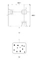
先ず、本開示の第1の実施形態に係る微小粒子分析装置の構成について説明する。図1は本実施形態の微小粒子分析装置の構成を模式的に示す図である。図1に示すように、本実施形態の微小粒子分析装置1は、サンプル流4内を1列になって通流する微小粒子5に、レーザ光を照射する光照射部2と、レーザ光が照射された微小粒子5から発せられた蛍光及び/又は散乱光を検出する検出部3が設けられている。
<1. First Embodiment>
[Overall configuration of microparticle analyzer]
First, the configuration of the fine particle analyzer according to the first embodiment of the present disclosure will be described. FIG. 1 is a diagram schematically showing the configuration of the fine particle analyzer of this embodiment. As shown in FIG. 1, the
[光照射部2]
光照射部2は、少なくとも、励起光となるレーザ光を発生する光源21と、光源21から出射したレーザ光のビームパターンをトップハット型に変換する光ファイバ25と、光源21の駆動を制御する光源駆動制御部27とを備えている。また、光照射部2には、必要に応じて、コリメータレンズ22、ミラー23、集光レンズ24,26などを設けることができる。
[Light irradiation unit 2]
The light irradiation unit 2 controls at least the
図2(a)はトップハット型光ファイバ25から出射したレーザ光のビーム強度を示す図であり、図2(b)はそのビームスポット形状を示す図である。トップハット型光ファイバ25の入射端25aから入射したレーザ光は、コア内を多くのモードに分かれて伝搬し、コア中を広がりながら進み、出射端25bからコアの全領域に均一に広がった状態で出射される。
2A is a diagram showing the beam intensity of the laser light emitted from the top hat type
そして、トップハット型光ファイバ25を通過し、サンプル流4に照射される励起光(レーザ光)の断面強度は、図2(a)に示すように、出射端25bにおけるコア形状に対応した形状(出射スポットL)で、略均一に分布する。なお、トップハット型光ファイバ25の出射端25bにおけるコア形状は、矩形状又は矩形状に近い形状(以下、略矩形状という。)であることが望ましい。これにより、微小粒子の通流位置が変動しても、レーザ光を均一に照射することができる。
Then, the cross-sectional intensity of the excitation light (laser light) that passes through the top hat type
一方、トップハット型光ファイバ25を使用した場合でも、近視野像(NFP)のスペックルにより、ビームがトップハット形状を成さなかったり、モードホップに起因する光源21の変動が生じたりすることがある(図2(a)の破線で囲った部分参照)。そして、出射スポットLにおけるビーム強度が弱い領域(図2(b)の黒で塗りつぶした部分)を微小粒子が通過すると、検出精度を低下させる原因となる。
On the other hand, even when the top-hat type
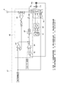
そこで、本実施形態の微小粒子分析装置1においては、光源21に半導体レーザ(レーザダイオード)を使用し、光源駆動制御部27によって、このレーザダイオードの駆動を制御する。図3は光源駆動制御部27の構成を示す図である。また、図4(a)〜(e)は図3に示す高周波駆動回路50の動作を示す図である。なお、図3においては、光源21にレーザダイオードLDを使用し、検出器33にフォトダイオードPDを使用した場合を例に示している。
Therefore, in the
光源駆動制御部27は、光源21であるレーザダイオードLDに、直流電流に大振幅の高周波電流を重畳した駆動電流を供給するものであり、少なくとも、高周波発振器(重畳信号発振回路51)と、広帯域増幅器(高周波増幅回路52)と、電流スイッチ回路(高周波駆動回路50)とを備えている。また、重畳信号発振回路51、高周波増幅回路52及び高周波駆動回路50は、直流的に結合されている。
The light
高周波駆動回路50は、光源21であるレーザダイオードLDを駆動するものであり、レーザダイオードLDの近傍に設けられており、例えば、エミッタ結合の電流スイッチ回路の構成をとることができる。ただし、電流スイッチ回路そのものの回路構成で駆動すると、重畳のONとOFFとで、レーザダイオードLDに流れる平均電流値に変化が生じてしまう。つまり、通常のエミッタ結合の電流スイッチ回路は、APC(Auto Power Control)などを経由して供給される直流電流から、パルス状の電流を引き算する形式であるため、パルス形状に応じて平均電流が低下する。
The high-
このため、低下した分の電流を補う必要があるが、仮に、APCによって電流低下分を賄おうとすると、重畳振幅を上昇させたときに、APCが自動的に平均電流を上昇させてしまうため、レーザダイオードLDの閾値電流を割り込みにくくなる。その結果、高周波重畳の効果が低くなり、更には効果がなくなる場合もある。 For this reason, it is necessary to compensate for the reduced current, but if APC tries to cover the current drop, APC automatically increases the average current when the superimposed amplitude is increased. It becomes difficult to interrupt the threshold current of the laser diode LD. As a result, the effect of high-frequency superposition is reduced, and the effect may be lost.
そこで、本実施形態の微小粒子分析装置1においては、重畳をかけても平均電流が変化しない構成を採っている。具体的には、高周波駆動回路50について、電流スイッチ回路の出力端子のうち一方をレーザダイオードLDに接続すると共に、他方を外部に接続し、レーザダイオードLDに供給されない電流を、外部に取り出す構成としている。そして、その取りだした平均電流と設定振幅で演算を行い、更に、APC60からの制御電流Dに直流電流Cを加算する。これにより、高周波重畳のON/OFFに関わらず、レーザダイオードLDに流れる平均電流を一定にすることができる。
Therefore, the
なお、光源駆動制御部27におけるAPC60は、例えば、引き算回路61,62、電流電圧変改回路63、差動増幅回路64、電圧電流変換回路65などで構成され、電源6に接続されている。
Note that the
また、高周波駆動回路50は、レーザダイオードLDの近傍(数mm以内)に配置されているが、一方の直流の加算電流Cは、APC60による制御電流Dに加算して、駆動することが可能であるため、レーザダイオードLDから離れた位置(数十cm)に配置してもよい。ただし、その場合、高周波電流と、直流電流とを混合する前に、コイルにより交流的に分離することが望ましい。
The high-
図4(a)〜(e)は図3に示す高周波駆動回路50の動作を示す図である。重畳の振幅Aを、図4(d)に示す設定にすると、図4(e)に示すように、重畳電流の平均、即ちレーザダイオードLDに接続されていない方の電流スイッチの出力が検出される。図4(a)に示すように、この値をBとすると、加算すべき直流電流はCとなる。そして、図4(b)に示すように、このCを、APC60からの制御電流D(直流)に加算して、レーザダイオードLDに印加する。
4A to 4E are diagrams showing the operation of the high-
そうすると、図4(c)に示すように、レーザダイオードLDには、C+Dの直流電流とスイッチング電流Gの引き算した電流が流れる。これにより、レーザダイオードLDへの電流平均値(D×gm−k×gm×A)+k×gm×A=D×gmとなり、レーザダイオードLDに流れる平均電流は一致することとなる。なお、図4(b)及び図4(c)の縦軸方向のディメンジョンは、図4(b)から図4(c)へは、gmをかける関係、即ちP×gm=Eとなる。なお、gmは、電圧を電流に変換するアンプの固有係数である。 Then, as shown in FIG. 4C, a current obtained by subtracting the DC current of C + D and the switching current G flows through the laser diode LD. As a result, the average current value to the laser diode LD (D × gm−k × gm × A) + k × gm × A = D × gm is obtained, and the average currents flowing through the laser diode LD coincide with each other. In addition, the dimension of the vertical axis | shaft direction of FIG.4 (b) and FIG.4 (c) becomes the relationship which applies gm from FIG.4 (b) to FIG.4 (c), ie, Pxgm = E. Gm is an intrinsic coefficient of an amplifier that converts a voltage into a current.
前述した方法により、直流電流に高周波電流を重畳した駆動電流を光源21に供給することで、トップハット型光ファイバ25の出射端25bから出射するレーザ光のスペックルを軽減できると共に、モードホップによる光源21のパワー変動を抑制することが可能となる。
By supplying a driving current in which a high-frequency current is superimposed on a direct current to the
なお、光源駆動制御部27においては、フォトダイオードPDにより検出した結果を、APC回路にフィードバックしてもよい。
Note that the light source
[検出部3]
検出部3は、例えば、CCD(Charge Coupled Device;電荷結合素子)及びPMT(Photo-Multiplier Tube;光電子増倍管)などの光検出器33、対物レンズ31、波長フィルタ32などを備えている。そして、微小粒子5から発せられた蛍光及び/又は散乱光は、対物レンズ31で集光された後、波長フィルタ32により検出対象の波長のみが反射され、光検出器33に入射する。
[Detection unit 3]
The detection unit 3 includes, for example, a
[動作]
次に、微小粒子分析装置1の動作、即ち、本実施形態の微小粒子分析装置1を使用して微小粒子を分析する方法について説明する。本実施形態の微小粒子分析方法において測定される「微小粒子」には、細胞、微生物及びリボゾームなどの生体関連微小粒子、又はラテックス粒子、ゲル粒子及び工業用粒子などの合成粒子などが広く含まれる。
[Operation]
Next, the operation of the
そして、生体関連微小粒子には、各種細胞を構成する染色体、リボゾーム、ミトコンドリア、オルガネラ(細胞小器官)などが含まれる。また、細胞には、植物細胞、動物細胞及び血球系細胞などが含まれる。更に、微生物には、大腸菌などの細菌類、タバコモザイクウイルスなどのウイルス類、イースト菌などの菌類などが含まれる。この生体関連微小粒子には、核酸や蛋白質、これらの複合体などの生体関連高分子も包含され得るものとする。 The living body-related microparticles include chromosomes, ribosomes, mitochondria, organelles (organelles) and the like that constitute various cells. The cells include plant cells, animal cells, blood cells, and the like. Furthermore, microorganisms include bacteria such as Escherichia coli, viruses such as tobacco mosaic virus, and fungi such as yeast. The biologically relevant microparticles may include biologically relevant polymers such as nucleic acids, proteins, and complexes thereof.
一方、工業用粒子としては、例えば有機高分子材料、無機材料又は金属材料などで形成されたものが挙げられる。有機高分子材料としては、ポリスチレン、スチレン・ジビニルベンゼン、ポリメチルメタクリレートなどを使用することができる。また、無機材料としては、ガラス、シリカ及び磁性材料などを使用することができる。金属材料としては、例えば金コロイド及びアルミニウムなどを使用することができる。なお、これら微小粒子の形状は、一般には球形であるが、非球形であってもよく、また大きさや質量なども特に限定されない。 On the other hand, examples of the industrial particles include those formed of an organic polymer material, an inorganic material, or a metal material. As the organic polymer material, polystyrene, styrene / divinylbenzene, polymethyl methacrylate, or the like can be used. Moreover, as an inorganic material, glass, silica, a magnetic material, etc. can be used. As the metal material, for example, gold colloid and aluminum can be used. In addition, although the shape of these fine particles is generally spherical, it may be non-spherical, and the size and mass are not particularly limited.
本実施形態の微小粒子分析装置1においては、光照射部2の光源21から出射されたレーザ光を、トップハット型光ファイバ25を介して、マイクロチップ(図示せず)に形成された流路内を通流する微小粒子5に照射する。そして、微小粒子5から発せられた蛍光及び/又は散乱光を、検出部3の対物レンズ31で捕捉した後、波長フィルタ32により試料から発せられた光以外の外乱成分を除去し、光検出器33で検出する。
In the
その際、光源駆動制御部27において、直流電流に、大振幅の高周波電流を重畳し、これを駆動電流として光源21を構成するレーザダイオードLDに供給する。具体的には、光源駆動制御部27に設けられた高周波駆動回路50において、パルス状のsink電流を生成し、レーザダイオードLDに流れる直流電流を「減らす」又は「減らさない」の動作を繰り返し行う。なお、ここでいう「大振幅の高周波電流」とは、振幅が100mAp−p以上の電流をいう。
At that time, the light source
以上詳述したように、本実施形態の微小粒子分析装置1においては、光源21から出射したレーザ光を、トップハット型光ファイバ25を介して微小粒子5に照射しているため、励起光(レーザ光)の断面強度を均一にすることができる。また、光源駆動制御部27により、高周波重畳によるレーザダイオードLDの波長スペクトルのマルチモード化を図っているため、光ファイバの出射端面から発せられるNFPのスペックルを抑制することができると共に、モードホップによる光源であるレーザダイオードLDのパワー変動を抑制することも期待できる。
As described above in detail, in the
そして、本実施形態の微小粒子分析装置1では、高周波駆動回路50を、電流で駆動する形式とし、重畳電流がレーザの微分抵抗の温度変化で変動しにくい構成としている。また、高周波重畳電流の振幅によらず、光源21を構成するレーザダイオードLDのもつ閾値電流を割り込む時間及び間隔(デューティ)が変わらないようパルス駆動としている。更に、高周波駆動回路50におけるレーザダイオードLD駆動側の電源電圧は、レーザダイオードLDの通電電圧と、APC及び重畳用の加算電流Cを利用した構成としている。
In the
その結果、光源に起因するノイズを低減することができると共に、マイクロチップを使用した測定においても、高精度でかつ安定した測定を行うことができる。これにより、光軸調整の難易度だけでなく、チップに形成される流路の位置精度や装置へのチップの取り付け精度も緩和されるため、作業者の負担が軽減されると共に、測定安定性(信頼性)の向上にも貢献することができる。 As a result, noise caused by the light source can be reduced, and highly accurate and stable measurement can be performed even in measurement using a microchip. As a result, not only the difficulty of optical axis adjustment but also the positional accuracy of the flow path formed in the chip and the mounting accuracy of the chip to the device are alleviated, reducing the burden on the operator and measuring stability. (Reliability) can also be improved.
<2.第1の実施の形態の変形例>
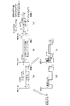
本開示の微小粒子分析装置は、図1に示す構成に限定されるものではなく、光照射部に、少なくとも、光源、トップハット型光ファイバ及び光源駆動制御部が設けられていればよい。図5は本開示の第1の実施形態の変形例に係る微小粒子分析装置の構成を模式的に示す図である。
<2. Modification of First Embodiment>
The fine particle analyzer of the present disclosure is not limited to the configuration illustrated in FIG. 1, and it is sufficient that at least a light source, a top hat type optical fiber, and a light source drive control unit are provided in the light irradiation unit. FIG. 5 is a diagram schematically illustrating a configuration of a microparticle analysis apparatus according to a modification of the first embodiment of the present disclosure.
例えば、図5に示す本開示の変形例の微小粒子分析装置41のように、光照射部42に、結晶の粗密波による回折を利用して、光の周波数を変化させる音響光学素子(AOM)28が配設されていてもよい。この場合、音響素子28は、光源21とトップハット型光ファイバ25との間に配置される。このように、音響素子28を併用することにより、出射スポット内のビーム強度を、更に均一にすることができる。即ち、音響素子28を併用することにより、トップハット型光ファイバ25によりレーザ光のビームパターンをトップハット型にした効果を、更に高めることができる。
For example, an acousto-optic device (AOM) that changes the frequency of light using the diffraction due to the density wave of the crystal in the
なお、本開示は、以下のような構成をとることもできる。
(1)
流路内を通流する微小粒子にレーザ光を照射する光照射部と、
前記レーザ光が照射された微小粒子から発せられた光を検出する検出部と、
を有し、
前記光照射部は、少なくとも、
半導体レーザからなる光源と、
該光源から発生したレーザ光のビームパターンをトップハット型に変換する光ファイバと、
前記光源に直流電流に高周波電流を重畳した駆動電流を供給する光源駆動制御部と、
を備える微小粒子分析装置。
(2)
前記光源駆動制御部には少なくとも、高周波発振器と、広帯域増幅器と、電流スイッチ回路とが設けられており、これらが直流的に結合されている(1)に記載の微小粒子分析装置。
(3)
前記電流スイッチ回路は、エミッタ結合型回路であり、光源に接続されていない出力端子から取り出された平均電流に基づいて重畳電流を調節する(2)に記載の微小粒子分析装置。
(4)
前記光ファイバの出射端側のコアの断面形状が略矩形状である(1)〜(3)のいずれかに記載の微小粒子分析装置。
(5)
半導体レーザからなる光源から出射したレーザ光を光ファイバに入射し、該光ファイバにより前記レーザ光のビームパターンをトップハット型に変換した後、流路内を通流する微小粒子に変換後のレーザ光を照射する工程と、
前記レーザ光が照射された微小粒子から発せられた光を検出する工程と、
を有し、
直流電流に高周波電流を重畳した駆動電流を、前記光源に供給する微小粒子分析方法。
In addition, this indication can also take the following structures.
(1)
A light irradiator for irradiating the fine particles flowing through the flow path with laser light;
A detection unit for detecting light emitted from the microparticles irradiated with the laser light;
Have
The light irradiation unit is at least
A light source comprising a semiconductor laser;
An optical fiber for converting a beam pattern of laser light generated from the light source into a top-hat type;
A light source drive controller for supplying a drive current in which a high-frequency current is superimposed on a direct current to the light source;
A fine particle analyzer.
(2)
The fine particle analyzer according to (1), wherein the light source drive control unit is provided with at least a high-frequency oscillator, a broadband amplifier, and a current switch circuit, which are coupled in a direct current manner.
(3)
The fine particle analyzer according to (2), wherein the current switch circuit is an emitter-coupled circuit and adjusts the superimposed current based on an average current extracted from an output terminal not connected to a light source.
(4)
The microparticle analyzer according to any one of (1) to (3), wherein a cross-sectional shape of the core on the emission end side of the optical fiber is substantially rectangular.
(5)
Laser light emitted from a light source composed of a semiconductor laser is incident on an optical fiber, the laser light beam pattern is converted into a top hat type by the optical fiber, and then converted into microparticles that flow through the flow path. Irradiating with light;
Detecting light emitted from fine particles irradiated with the laser beam;
Have
A fine particle analysis method for supplying a driving current in which a high-frequency current is superimposed on a direct current to the light source.
1、41 微小粒子分析装置
2、42 光照射部
3 検出部
4 サンプル流
5 微小粒子
6 電源
21 光源
25 光ファイバ
27 光源駆動制御部
28 音響素子
50 高周波駆動回路
51 重畳信号発振回路
52 高周波増幅回路
60 APC
DESCRIPTION OF
Claims (3)
前記レーザ光が照射された微小粒子から発せられた光を検出する検出部と、
を有し、
前記光照射部は、少なくとも、
半導体レーザからなる光源と、
該光源から発生したレーザ光のビームパターンをトップハット型に変換する光ファイバと、
前記光源に直流電流に高周波電流を重畳した駆動電流を供給する光源駆動制御部と、
を備える微小粒子分析装置であって、
前記光源駆動制御部には、少なくとも、高周波発振器と、広帯域増幅器と、エミッタ結合型回路であり前記光源に接続されていない出力端子から取り出された平均電流に基づいて重畳電流を調節する電流スイッチ回路と、が設けられており、これらが直流的に結合されている、微小粒子分析装置。 A light irradiator for irradiating the fine particles flowing through the flow path with laser light;
A detection unit for detecting light emitted from the microparticles irradiated with the laser light;
Have
The light irradiation unit is at least
A light source comprising a semiconductor laser;
An optical fiber for converting a beam pattern of laser light generated from the light source into a top-hat type;
A light source drive controller for supplying a drive current in which a high-frequency current is superimposed on a direct current to the light source;
A microparticle analyzer comprising :
The light source drive control unit includes at least a high-frequency oscillator, a broadband amplifier, and a current switch circuit that adjusts a superimposed current based on an average current extracted from an output terminal that is an emitter-coupled circuit and is not connected to the light source. Are provided, and these are coupled in a direct current manner .
前記レーザ光が照射された微小粒子から発せられた光を検出する工程と、
を有し、
高周波発振器と、広帯域増幅器と、エミッタ結合型回路であり前記光源に接続されていない出力端子から取り出された平均電流に基づいて重畳電流を調節する電流スイッチ回路と、を設け、これらを直流的に結合することにより、前記光源に直流電流に高周波電流を重畳した駆動電流を供給する微小粒子分析方法。
Laser light emitted from a light source composed of a semiconductor laser is incident on an optical fiber, the laser light beam pattern is converted into a top hat type by the optical fiber, and then converted into microparticles that flow through the flow path. Irradiating with light;
Detecting light emitted from fine particles irradiated with the laser beam;
Have
A high-frequency oscillator, a wide-band amplifier, and a current switch circuit that adjusts a superimposed current based on an average current extracted from an output terminal that is an emitter-coupled circuit and is not connected to the light source. A fine particle analysis method for supplying a driving current in which a high-frequency current is superimposed on a direct current to the light source by combining the light sources .
Priority Applications (3)
| Application Number | Priority Date | Filing Date | Title |
|---|---|---|---|
| JP2011080621A JP5765022B2 (en) | 2011-03-31 | 2011-03-31 | Fine particle analyzer and fine particle analysis method |
| US13/417,400 US8804120B2 (en) | 2011-03-31 | 2012-03-12 | Fine particle analyzing apparatus and fine particle analyzing method |
| CN201210081015.6A CN102735656B (en) | 2011-03-31 | 2012-03-23 | Fine particle analytical equipment and fine particle analytical approach |
Applications Claiming Priority (1)
| Application Number | Priority Date | Filing Date | Title |
|---|---|---|---|
| JP2011080621A JP5765022B2 (en) | 2011-03-31 | 2011-03-31 | Fine particle analyzer and fine particle analysis method |
Publications (3)
| Publication Number | Publication Date |
|---|---|
| JP2012215458A JP2012215458A (en) | 2012-11-08 |
| JP2012215458A5 JP2012215458A5 (en) | 2014-04-10 |
| JP5765022B2 true JP5765022B2 (en) | 2015-08-19 |
Family
ID=46926863
Family Applications (1)
| Application Number | Title | Priority Date | Filing Date |
|---|---|---|---|
| JP2011080621A Expired - Fee Related JP5765022B2 (en) | 2011-03-31 | 2011-03-31 | Fine particle analyzer and fine particle analysis method |
Country Status (3)
| Country | Link |
|---|---|
| US (1) | US8804120B2 (en) |
| JP (1) | JP5765022B2 (en) |
| CN (1) | CN102735656B (en) |
Families Citing this family (8)
| Publication number | Priority date | Publication date | Assignee | Title |
|---|---|---|---|---|
| JPWO2013145836A1 (en) * | 2012-03-30 | 2015-12-10 | ソニー株式会社 | Microchip type optical measuring apparatus and optical position adjusting method in the apparatus |
| JP6537252B2 (en) * | 2014-11-14 | 2019-07-03 | シスメックス株式会社 | Sample measurement device |
| CN105987870A (en) * | 2015-02-10 | 2016-10-05 | 博奥生物集团有限公司 | Flow cell sorting system and its focusing detection method and fluidic chip |
| US11181455B2 (en) * | 2018-11-12 | 2021-11-23 | Particle Measuring Systems, Inc. | Calibration verification for optical particle analyzers |
| KR102247677B1 (en) * | 2019-09-27 | 2021-05-03 | 주식회사 마하테크 | minute plastic detection apparatus |
| WO2021075310A1 (en) * | 2019-10-15 | 2021-04-22 | 株式会社堀場製作所 | Particle analysis device and particle analysis unit |
| KR102569612B1 (en) * | 2021-07-20 | 2023-08-25 | 한국기계연구원 | Apparatus for diluting exhaust gas |
| KR102577017B1 (en) * | 2023-06-22 | 2023-09-11 | 한남대학교 산학협력단 | Laser diode speckle reduction device |
Family Cites Families (17)
| Publication number | Priority date | Publication date | Assignee | Title |
|---|---|---|---|---|
| WO1992008120A1 (en) * | 1990-10-29 | 1992-05-14 | Macquarie University | Pulsed laser flow cytometry |
| DE69228550T2 (en) * | 1991-09-06 | 1999-08-19 | Commw Scient Ind Res Org | MEASURING METHOD AND DEVICE |
| JPH05232012A (en) | 1992-02-22 | 1993-09-07 | Horiba Ltd | Fine particle measuring device |
| JP3531199B2 (en) * | 1994-02-22 | 2004-05-24 | 三菱電機株式会社 | Optical transmission equipment |
| JPH09178645A (en) * | 1995-12-26 | 1997-07-11 | Rion Co Ltd | Light-scattering type particle counter |
| JP2002335041A (en) * | 2001-05-07 | 2002-11-22 | Sony Corp | Laser driver and laser driving method |
| US6809820B2 (en) * | 2002-04-18 | 2004-10-26 | National Research Council Of Canada | Small particle analysis by laser induced incandescence |
| US7525659B2 (en) * | 2003-01-15 | 2009-04-28 | Negevtech Ltd. | System for detection of water defects |
| JP2004257737A (en) * | 2003-02-24 | 2004-09-16 | Mitsui Eng & Shipbuild Co Ltd | Biochip reader |
| FR2856536B1 (en) * | 2003-06-20 | 2005-09-30 | Airbus France | METHOD FOR LIGHTING PARTICLES FOR THE FORMATION OF THEIR IMAGES |
| JP2005172465A (en) | 2003-12-08 | 2005-06-30 | Sysmex Corp | Particle measuring instrument |
| JP3995684B2 (en) * | 2004-12-21 | 2007-10-24 | リオン株式会社 | Particle counter |
| GB0701477D0 (en) * | 2007-01-25 | 2007-03-07 | Renishaw Plc | Spectroscopic apparatus and methods |
| JP5025388B2 (en) | 2007-08-27 | 2012-09-12 | シスメックス株式会社 | Sample analyzer and sample analysis method |
| JP2011163787A (en) * | 2010-02-05 | 2011-08-25 | Sony Corp | Fine particle analyzer and fine particle analyzing method |
| JP2011245818A (en) * | 2010-05-31 | 2011-12-08 | Fujifilm Corp | Original plate of relief printing plate for laser engraving, method for making relief printing plate, and relief printing plate |
| US8384045B2 (en) * | 2010-07-01 | 2013-02-26 | Sony Corporation | Minute particle analyzing device and method |
-
2011
- 2011-03-31 JP JP2011080621A patent/JP5765022B2/en not_active Expired - Fee Related
-
2012
- 2012-03-12 US US13/417,400 patent/US8804120B2/en not_active Expired - Fee Related
- 2012-03-23 CN CN201210081015.6A patent/CN102735656B/en not_active Expired - Fee Related
Also Published As
| Publication number | Publication date |
|---|---|
| CN102735656A (en) | 2012-10-17 |
| JP2012215458A (en) | 2012-11-08 |
| CN102735656B (en) | 2016-03-02 |
| US8804120B2 (en) | 2014-08-12 |
| US20120250018A1 (en) | 2012-10-04 |
Similar Documents
| Publication | Publication Date | Title |
|---|---|---|
| JP5765022B2 (en) | Fine particle analyzer and fine particle analysis method | |
| CN105393104B (en) | Particle analysis device and particle analysis method | |
| US9891159B2 (en) | Microparticle analysis apparatus to improve analytical precision based on detection of forward-scattered light | |
| JP4509154B2 (en) | Light irradiation apparatus, particle analysis apparatus, and light irradiation method | |
| JP4990746B2 (en) | Apparatus and method for separating biological particles contained in a liquid flow | |
| JP5534214B2 (en) | Flow cytometer and flow cytometry method | |
| JP5381741B2 (en) | Optical measuring apparatus and optical measuring method | |
| JP4556975B2 (en) | Light irradiation method, light irradiation apparatus, and particle analysis apparatus | |
| US9417173B2 (en) | Fine particle measurement device, and laminar flow monitoring method and fine particle analysis method in fine particle measurement device | |
| WO2020149042A1 (en) | Microparticle isolation device, microparticle isolation system, droplet isolation device, droplet control device, and droplet control program | |
| US10302545B2 (en) | Automated drop delay calculation | |
| JP4022830B2 (en) | Fluorescence detection device | |
| JP2014081330A (en) | Fine particle detection device and fine particle detection method | |
| JP2013160672A (en) | Optical system for fluorescence detection and fine particle analyzing apparatus | |
| JP2009063462A (en) | Optical measuring instrument and particulate analyzer | |
| JP2014115121A (en) | Microparticle analyzer, and microparticle analysis method | |
| JP2013195208A (en) | Fine particle measuring instrument | |
| US11204310B2 (en) | Optical flow cytometer for epi fluorescence measurement | |
| JP2012199359A (en) | Laser irradiation device and microparticle measuring apparatus | |
| CN115397601A (en) | Laser processing monitoring device, laser processing monitoring method, and laser processing device | |
| WO2022264481A1 (en) | Particle sorting device, particle sorting method and program | |
| JP2017142142A (en) | Particle detection sensor, portable gas monitor, and particle detection method | |
| JP6249049B2 (en) | Fine particle measuring device | |
| JPH01301146A (en) | Fine particulate characteristic measuring instrument | |
| JP2017142141A (en) | Particle detection sensor, mobile entity onboard gas monitor, and particle detection method |
Legal Events
| Date | Code | Title | Description |
|---|---|---|---|
| A521 | Request for written amendment filed |
Free format text: JAPANESE INTERMEDIATE CODE: A523 Effective date: 20140224 |
|
| A621 | Written request for application examination |
Free format text: JAPANESE INTERMEDIATE CODE: A621 Effective date: 20140224 |
|
| A977 | Report on retrieval |
Free format text: JAPANESE INTERMEDIATE CODE: A971007 Effective date: 20141003 |
|
| A131 | Notification of reasons for refusal |
Free format text: JAPANESE INTERMEDIATE CODE: A131 Effective date: 20141014 |
|
| A521 | Request for written amendment filed |
Free format text: JAPANESE INTERMEDIATE CODE: A523 Effective date: 20141201 |
|
| TRDD | Decision of grant or rejection written | ||
| A01 | Written decision to grant a patent or to grant a registration (utility model) |
Free format text: JAPANESE INTERMEDIATE CODE: A01 Effective date: 20150519 |
|
| A61 | First payment of annual fees (during grant procedure) |
Free format text: JAPANESE INTERMEDIATE CODE: A61 Effective date: 20150601 |
|
| R151 | Written notification of patent or utility model registration |
Ref document number: 5765022 Country of ref document: JP Free format text: JAPANESE INTERMEDIATE CODE: R151 |
|
| R250 | Receipt of annual fees |
Free format text: JAPANESE INTERMEDIATE CODE: R250 |
|
| R250 | Receipt of annual fees |
Free format text: JAPANESE INTERMEDIATE CODE: R250 |
|
| LAPS | Cancellation because of no payment of annual fees |