JP5763639B2 - Adjustable furniture - Google Patents
Adjustable furniture Download PDFInfo
- Publication number
- JP5763639B2 JP5763639B2 JP2012525201A JP2012525201A JP5763639B2 JP 5763639 B2 JP5763639 B2 JP 5763639B2 JP 2012525201 A JP2012525201 A JP 2012525201A JP 2012525201 A JP2012525201 A JP 2012525201A JP 5763639 B2 JP5763639 B2 JP 5763639B2
- Authority
- JP
- Japan
- Prior art keywords
- furniture
- support
- support portion
- guide
- furniture according
- Prior art date
- Legal status (The legal status is an assumption and is not a legal conclusion. Google has not performed a legal analysis and makes no representation as to the accuracy of the status listed.)
- Expired - Fee Related
Links
Images


Classifications
-
- A—HUMAN NECESSITIES
- A47—FURNITURE; DOMESTIC ARTICLES OR APPLIANCES; COFFEE MILLS; SPICE MILLS; SUCTION CLEANERS IN GENERAL
- A47C—CHAIRS; SOFAS; BEDS
- A47C1/00—Chairs adapted for special purposes
- A47C1/02—Reclining or easy chairs
- A47C1/031—Reclining or easy chairs having coupled concurrently adjustable supporting parts
- A47C1/032—Reclining or easy chairs having coupled concurrently adjustable supporting parts the parts being movably-coupled seat and back-rest
- A47C1/03294—Reclining or easy chairs having coupled concurrently adjustable supporting parts the parts being movably-coupled seat and back-rest slidingly movable in the base frame, e.g. by rollers
-
- A—HUMAN NECESSITIES
- A47—FURNITURE; DOMESTIC ARTICLES OR APPLIANCES; COFFEE MILLS; SPICE MILLS; SUCTION CLEANERS IN GENERAL
- A47C—CHAIRS; SOFAS; BEDS
- A47C1/00—Chairs adapted for special purposes
- A47C1/02—Reclining or easy chairs
- A47C1/031—Reclining or easy chairs having coupled concurrently adjustable supporting parts
- A47C1/034—Reclining or easy chairs having coupled concurrently adjustable supporting parts the parts including a leg-rest or foot-rest
- A47C1/035—Reclining or easy chairs having coupled concurrently adjustable supporting parts the parts including a leg-rest or foot-rest in combination with movably coupled seat and back-rest, i.e. the seat and back-rest being movably coupled in such a way that the extension mechanism of the foot-rest is actuated at least by the relative movements of seat and backrest
-
- A—HUMAN NECESSITIES
- A47—FURNITURE; DOMESTIC ARTICLES OR APPLIANCES; COFFEE MILLS; SPICE MILLS; SUCTION CLEANERS IN GENERAL
- A47C—CHAIRS; SOFAS; BEDS
- A47C17/00—Sofas; Couches; Beds
- A47C17/04—Seating furniture, e.g. sofas, couches, settees, or the like, with movable parts changeable to beds; Chair beds
- A47C17/16—Seating furniture changeable to beds by tilting or pivoting the back-rest
- A47C17/17—Seating furniture changeable to beds by tilting or pivoting the back-rest with coupled movement of back-rest and seat
- A47C17/175—Seating furniture changeable to beds by tilting or pivoting the back-rest with coupled movement of back-rest and seat with tilting or lifting seat-back-rest pivot
-
- A—HUMAN NECESSITIES
- A47—FURNITURE; DOMESTIC ARTICLES OR APPLIANCES; COFFEE MILLS; SPICE MILLS; SUCTION CLEANERS IN GENERAL
- A47C—CHAIRS; SOFAS; BEDS
- A47C20/00—Head -, foot -, or like rests for beds, sofas or the like
- A47C20/04—Head -, foot -, or like rests for beds, sofas or the like with adjustable inclination
-
- A—HUMAN NECESSITIES
- A47—FURNITURE; DOMESTIC ARTICLES OR APPLIANCES; COFFEE MILLS; SPICE MILLS; SUCTION CLEANERS IN GENERAL
- A47C—CHAIRS; SOFAS; BEDS
- A47C20/00—Head -, foot -, or like rests for beds, sofas or the like
- A47C20/08—Head -, foot -, or like rests for beds, sofas or the like with means for adjusting two or more rests simultaneously
-
- A—HUMAN NECESSITIES
- A47—FURNITURE; DOMESTIC ARTICLES OR APPLIANCES; COFFEE MILLS; SPICE MILLS; SUCTION CLEANERS IN GENERAL
- A47C—CHAIRS; SOFAS; BEDS
- A47C7/00—Parts, details, or accessories of chairs or stools
- A47C7/50—Supports for the feet or the legs coupled to fixed parts of the chair
-
- A—HUMAN NECESSITIES
- A47—FURNITURE; DOMESTIC ARTICLES OR APPLIANCES; COFFEE MILLS; SPICE MILLS; SUCTION CLEANERS IN GENERAL
- A47C—CHAIRS; SOFAS; BEDS
- A47C7/00—Parts, details, or accessories of chairs or stools
- A47C7/54—Supports for the arms
Landscapes
- Health & Medical Sciences (AREA)
- General Health & Medical Sciences (AREA)
- Dentistry (AREA)
- Nursing (AREA)
- Chairs For Special Purposes, Such As Reclining Chairs (AREA)
- Special Chairs (AREA)
- Chair Legs, Seat Parts, And Backrests (AREA)
- Chairs Characterized By Structure (AREA)
- Cabinets, Racks, Or The Like Of Rigid Construction (AREA)
- Legs For Furniture In General (AREA)
Description
本発明は、家具の一部の位置を別の部分に対して移動させることができる、椅子、ベッド等の調整可能な家具に関するものである。この調整は電気モータ等を用いて動力供給されてもよく、あるいは手動であってもよい。 The present invention relates to adjustable furniture, such as chairs and beds, which can move the position of one piece of furniture relative to another. This adjustment may be powered using an electric motor or the like, or may be manual.
リクライニング位置を与えるために背もたれの角度を変えることができる、および/または可動式足置きを前方かつ外側に移動させることができる調整可能な椅子が知られている。調節が手動または1以上の電気モータでなされるこの種のリクライニング椅子は有用である。一部の電動椅子は椅子の座部を傾ける機能を有し、ユーザが座位から立位へと椅子から離れる補助をする。ベッドのヘッドと上側背支持部を動かしてベッドの他の部分に対するこの部分の傾きを調整できる、調整可能なベッドも知られている。背もたれが部屋の壁または他の家具製品に近接している状態でリクライニング椅子を配置することができるだけではなく、壁と干渉することなく背もたれを傾けることができる、いわゆる「ゼロ壁」のリクライニング椅子が開発されてきた。これは、背もたれの運動が、背もたれが回動するよう連結された椅子の座部および周囲構造の運動と連動していることにより実現できる。 Adjustable chairs are known in which the angle of the backrest can be varied to provide a reclining position and / or the movable footrest can be moved forward and outward. This type of recliner chair, where the adjustment is made manually or with one or more electric motors, is useful. Some electric chairs have a function of tilting the seat of the chair, and assist the user to leave the chair from the sitting position to the standing position. Adjustable beds are also known in which the head and upper back support of the bed can be moved to adjust the inclination of this part relative to other parts of the bed. In addition to being able to position the reclining chair with the backrest close to the room wall or other furniture products, there is a so-called “zero wall” reclining chair that can tilt the backrest without interfering with the wall. Has been developed. This can be realized by the movement of the backrest being linked with the movement of the seat and the surrounding structure of the chair connected so that the backrest rotates.
通常、このような家具製品の可動部は、一般に一連の金属連結装置、ピンおよびブッシュを含む比較的複雑な支持機構に支持されており、これらの連結装置は家具の1以上の可動部がそれぞれの動作範囲を通して移動できるように可動である。このような支持機構は多くの場合、機械的に複雑で重量があり、輸送費用が掛かり、取り扱いおよび利用しにくい。これらの懸念事項は家具のデザインに厳しい制約を課してしまう。例えば、典型的な足置き付のリクライニング椅子の動作機構は約16Kg程度の重量がある。既知の支持機構における複雑な一連の連結装置および連結部には多くの場合、許容誤差などによる製造のばらつきが生じ、剛性または可動部の運動への耐性に影響を与える。これは、家具を調整するため、家具の同一部材にユーザによって異なる程度の力を適用することを必要とすることがある手動の家具の場合に特に不利となる。 Typically, the moving parts of such furniture products are generally supported by a relatively complex support mechanism including a series of metal coupling devices, pins and bushes, each of which is one or more movable parts of the furniture. It is movable so that it can move through its operating range. Such support mechanisms are often mechanically complex and heavy, expensive to transport, and difficult to handle and use. These concerns impose severe constraints on furniture design. For example, the operation mechanism of a typical reclining chair with a footrest has a weight of about 16 kg. In many cases, the complicated series of connecting devices and connecting parts in the known support mechanism has manufacturing variations due to tolerances and the like, which affects the rigidity or resistance to movement of the moving parts. This is particularly disadvantageous in the case of manual furniture that may require different levels of force applied by the user to the same piece of furniture to adjust the furniture.
従って、調整可能な家具製品用に改良した支持機構、特に従来の機構よりも機械的に複雑ではなく、重量がなく費用が掛からない支持機構が必要である。 Therefore, there is a need for an improved support mechanism for adjustable furniture products, particularly a support mechanism that is less mechanically complex and less expensive and less expensive than conventional mechanisms.
本発明の一態様によると、基部と、中間支持部と背支持部とを具える調整可能な家具が提供されており、この中間支持部は第1のガイド手段によって基部に対して動くようにガイドされ、背支持部は第2のガイド手段によって基部と中間支持部の双方に対して動くようにガイドされ、この第2のガイド手段は、基礎支持部および背支持部の一方に連結された少なくとも1のガイド部と、基礎支持部および背支持部の他方に連結された少なくとも1の従動部とを有する。背支持部は中間支持部に対して回動運動するように装着され、第1および第2のガイド手段は、使用時に、背支持部が中間支持部に対して回動すると中間支持部を基部に対して移動させるように配置される。 According to one aspect of the invention, there is provided an adjustable furniture comprising a base, an intermediate support and a back support, the intermediate support being moved relative to the base by a first guide means. The back support is guided by a second guide means to move relative to both the base and the intermediate support, and the second guide means is connected to one of the base support and the back support. At least one guide part and at least one driven part connected to the other of the basic support part and the back support part. The back support portion is mounted so as to rotate with respect to the intermediate support portion, and the first and second guide means are configured such that the intermediate support portion is the base when the back support portion rotates with respect to the intermediate support portion in use. It is arranged to move with respect to.
従って、本発明の上記態様は、中間支持部および背支持部が、それぞれの第1および第2のガイド手段によって連動するように互いに且つ基礎支持部に対して動く調整可能な家具を提供する。 Thus, the above aspect of the invention provides adjustable furniture in which the intermediate support and the back support move relative to each other and the base support so that they are interlocked by respective first and second guide means.
好適な一実施形態では、第1および第2のガイド手段は、連動している、基部および中間支持部に対する背支持部の回動運動と、基部に対する中間支持部の線形運動をもたらすように配置される。従って、この家具はいわゆる「ゼロ壁」機構を提供するように配置されてもよい。 In a preferred embodiment, the first and second guide means are arranged to provide interlocking rotational movement of the back support relative to the base and intermediate support and linear movement of the intermediate support relative to the base. Is done. Thus, the furniture may be arranged to provide a so-called “zero wall” mechanism.
好適には、背支持部はレバー機構の少なくとも一部を提供し、このレバー機構の運動がさらに中間部材を基部に対して移動させる。この方法では、レバーとして椅子の背もたれなどの家具製品の背支持部を利用し、例えばゼロ壁椅子の場合には前方の直線方向に中間部材を基部に対して移動させることにより、著しい機械的な利点を実現することができる。この方法では、着座したユーザの上半身の重量は分散され、背支持部を回動させて中間支持部を前方に動かすようにレバーを作動させることができる。一般に、基部に対して中間支持部を移動させて「ゼロ壁」機能を提供する電動アクチュエータを用いて背もたれを移動させることにより、調整可能なベッドの背もたれをほぼ同じ方法で利用することもできる。 Preferably, the back support provides at least a portion of the lever mechanism, and movement of the lever mechanism further moves the intermediate member relative to the base. This method uses a back support part of a furniture product such as a chair back as a lever, and in the case of a zero-wall chair, for example, by moving the intermediate member relative to the base in the linear direction of the front, Benefits can be realized. In this method, the weight of the upper body of the seated user is dispersed, and the lever can be operated to rotate the back support portion and move the intermediate support portion forward. In general, the adjustable backrest can be utilized in much the same way by moving the backrest using an electric actuator that provides a “zero wall” function by moving the intermediate support relative to the base.
好適な実施形態では、第2のガイド手段が支点を提供し、それを中心にレバー機構が機能して中間部材を基部に対して移動させる。この方法では、第2のガイド手段の固定部が機械的な利点(てこの作用)を与える支点を規定し、基部に対して中間支持部を移動させる。 In a preferred embodiment, the second guide means provides a fulcrum, about which a lever mechanism functions to move the intermediate member relative to the base. In this method, the fixed portion of the second guide means defines a fulcrum that provides a mechanical advantage (leverage action) and moves the intermediate support relative to the base.
中間支持部が基礎支持部に対して前方に移動したときに、中間支持部は基部に対して上方の斜めの直線軌道に従動するように、中間支持部は、基部に対して直線運動に、好適にはリクライニング椅子の斜めの直線運動に移動するよう配置されてもよい。この方法では、本発明の上記態様は特に、ゼロ壁のリクライニング椅子またはソファ機構での利用に適している。このような機構では、この機構は可動部が動作している間は本質的に平衡しているように、着座したユーザの上半身の体重は傾いているときの背支持部によってほぼ支持され、ユーザの下半身の体重は中間支持部によって支持されるという意味で着座したユーザの体重は釣り合いが取れている。調整可能なベッドの実施形態では、中間支持部の動きは斜めではない直線軌道に従動することが好ましいと想定される。 When the intermediate support part moves forward with respect to the base support part, the intermediate support part moves in a linear motion with respect to the base part so that the intermediate support part follows an oblique linear trajectory above the base part. Preferably it may be arranged to move in an oblique linear motion of the reclining chair. In this way, the above aspects of the invention are particularly suited for use in a zero wall reclining chair or sofa mechanism. In such a mechanism, the weight of the seated user's upper body is almost supported by the back support when tilted, so that the mechanism is essentially balanced while the moving part is in motion, The weight of the seated user is balanced in the sense that the lower body weight is supported by the intermediate support. In the adjustable bed embodiment, it is assumed that the movement of the intermediate support preferably follows a non-oblique linear track.
好適な実施形態では、背支持部は少なくとも1の連結レバーによって中間支持部に回動するよう連結されており、この連結レバーは中間支持部に回動するよう連結されている。この機構は容易に、組立式家具では一般的なように好適には取付/取外し可能な方法で、背支持部を連結レバーの一端で堅く固定することが可能であり、連結レバーの他端は中間支持部に回動するよう連結される。このレバー機構が背支持部の回動軸を規定する。 In a preferred embodiment, the back support is pivotally connected to the intermediate support by at least one connecting lever, which is connected to the intermediate support. This mechanism can be easily fixed in a manner that can be easily attached / removed as is common in prefabricated furniture, and the back support can be firmly fixed at one end of the connecting lever, the other end of the connecting lever being The intermediate support part is connected to rotate. This lever mechanism defines the rotational axis of the back support.
連結レバーは第2のガイド手段のガイドを有し、それぞれの従動部を収容することが好ましい。この方法では、ガイドおよび従動部は、家具が標準の向きにある状態で重力を受けて背支持部および連結レバーが下方に回動するのを防止する。従って、第2のガイド手段のガイドおよび従動部が係合すると、背支持部は回動軸を中心に下方に回動運動しにくい。他の実施形態では、連結レバーは第2のガイド手段の従動部を有するか連結され、基礎支持部は各ガイドを有する。 It is preferable that the connecting lever has a guide of the second guide means and accommodates each driven portion. In this method, the guide and the follower are prevented from rotating downward due to gravity when the furniture is in a standard orientation and receiving the gravity. Therefore, when the guide and the driven portion of the second guide means are engaged, the back support portion is difficult to rotate downward about the rotation axis. In another embodiment, the connecting lever has a follower of the second guide means or is connected and the foundation support has each guide.
第2のガイド手段のガイドは、1以上の湾曲部を有する曲線であることが好ましい。この方法では、回動軸を中心とした背支持部の下方運動は、基礎支持部に対する中間支持部の運動に影響を与える。 The guide of the second guide means is preferably a curve having one or more curved portions. In this method, the downward movement of the back support part around the rotation axis affects the movement of the intermediate support part relative to the base support part.
第2のガイド手段は連結レバーの支点を提供することが好ましい。この方法では、連結レバーまたはガイドに対する支点は、回動軸を中心に背支持部が回動運動している間、ガイドの長さに沿って移動する。この運動は回動軸を支点に対して移動させ、従動部が基部に対して固定された機構では、回動点をガイドの幾何学形状によって規定された経路に沿って移動させる。 The second guide means preferably provides a fulcrum for the connecting lever. In this method, the fulcrum for the connecting lever or the guide moves along the length of the guide while the back support portion is pivoting about the pivot axis. This movement moves the rotation axis with respect to the fulcrum, and in a mechanism in which the follower is fixed to the base, the rotation point is moved along a path defined by the geometry of the guide.
好適な実施形態では、各ガイドが、1以上の従動部が配置されるスロット、溝、トラックなどを具える。これは、容易に様々な支持要素の間の反力の伝達手段を提供する。 In a preferred embodiment, each guide comprises a slot, groove, track, etc. in which one or more followers are disposed. This easily provides a means for transmitting reaction forces between the various support elements.
好適な実施形態では、従動部はローラ、ベアリングなどを具える。好適には、各従動部はローラベアリングによって提供され、その外側要素はそれぞれの溝に配置される。 In a preferred embodiment, the follower comprises a roller, a bearing or the like. Preferably, each follower is provided by a roller bearing and its outer element is arranged in a respective groove.
基部は中間支持部が取り付けられるシャーシを具えることが好ましい。本発明は、シャーシが部分的または全体的に金属、木製またはプラスチックの材料または2以上のこのような材料の組み合わせで構成された実施形態を意図している。基部は、家具に加わる荷重に加えて家具の重量を支持するように床の上に家具を静置させる。基部には、家具業界で使用されるような、キャスタ、脚部などを設けてもよい。 The base preferably comprises a chassis to which the intermediate support is attached. The present invention contemplates embodiments in which the chassis is partially or wholly constructed of a metal, wood or plastic material or a combination of two or more such materials. The base rests the furniture on the floor to support the weight of the furniture in addition to the load applied to the furniture. The base may be provided with casters, legs, etc. as used in the furniture industry.
好適な実施形態では、リクライニング椅子またはソファの場合の座部支持部、あるいは調整可能なベッドの場合の上側背支持部が中間支持部に対して固定され、これにより座部または上側背支持部は、家具を調整する際に中間支持部と共に移動する。 In a preferred embodiment, the seat support in the case of a reclining chair or sofa, or the upper back support in the case of an adjustable bed is fixed to the intermediate support, so that the seat or upper back support is When moving furniture, move with the intermediate support.
第1のガイド手段は、基部および中間支持部の一方に連結された少なくとも1のガイドと、基部および中間支持部の他方に連結された少なくとも1の従動部とを有しうる。 The first guide means may have at least one guide connected to one of the base and the intermediate support and at least one follower connected to the other of the base and the intermediate support.
好適には、第1のガイド手段のガイドは中間支持部に連結され、従動部は基部に連結され、第2のガイド手段のガイドは背支持部に連結され、従動部は基部に連結される、あるいはその逆である。これについて、第1および第2のガイド手段の双方の従動部は基礎支持構造に対して有利に固定することができ、これにより従動部の位置は椅子を調整している間静止したままの状態となり、それぞれの第1および第2のガイド手段のガイドは調整時に従動部に対して移動する。 Preferably, the guide of the first guide means is connected to the intermediate support portion, the driven portion is connected to the base portion, the guide of the second guide means is connected to the back support portion, and the driven portion is connected to the base portion. Or vice versa. In this regard, the followers of both the first and second guide means can be advantageously fixed with respect to the basic support structure so that the position of the follower remains stationary while the chair is being adjusted. Thus, the guides of the first and second guide means move with respect to the follower during adjustment.
好適な一実施形態では、中間支持部は間隔が開いた一対の横側面パネルを有する。この側面パネルは、各従動部を収容する第1のガイド手段のガイドを有しうる。好適には、第1のガイド手段のガイドは側面パネルの各スロットとして提供される。この方法では、特に側面パネルがMDFまたはCNC加工法を用いて切断される同様の種類の板材で構成された家具では、ガイドスロットを各側面パネルの正確且つ繰り返し位置に容易に提供することが可能となる。 In a preferred embodiment, the intermediate support has a pair of spaced lateral side panels. This side panel may have a guide of the first guide means that accommodates each driven portion. Preferably, the guide of the first guide means is provided as a slot in the side panel. With this method, it is possible to easily provide guide slots to the exact and repeat positions of each side panel, especially for furniture made of similar types of plates where the side panels are cut using MDF or CNC machining methods. It becomes.
好適な一実施形態では各側面パネルは斜めの一対のスロットを具え、背支持部が直立または部分的に傾いた姿勢から下方に回動したときに基部に対して中間支持部を(家具の通常向きの)上方かつ前方にガイドする。 In a preferred embodiment, each side panel comprises a pair of diagonal slots, with the intermediate support (usually furniture) relative to the base when the back support is pivoted downward from an upright or partially tilted position. Guide upward and forward.
背支持部は各横側面パネルに回動するよう連結されることが好ましい。これにより、背支持部が回動軸を中心に回動したときに、背支持部は上記の方法で中間支持部を駆動させるレバーとして容易に機能することができる。 The back support is preferably connected to each lateral side panel so as to rotate. Thereby, when the back support part rotates around the rotation axis, the back support part can easily function as a lever for driving the intermediate support part by the above method.
好適な一実施形態では、中間支持部は外側支持部を規定し、基部は内側支持部を規定する。この方法では、上記の横側面パネルは、基礎支持部に対して家具の外側に配置された中間支持部の一部を構成することができる。この方法では、家具の可動部は横パネルによって保護することができる。本発明は、他の機構、特に外側支持部を形成する基礎支持部に対して中間支持部が内側支持部を形成する機構も意図している。他の実施形態は、基礎支持部および基部に連結された第1のガイド手段の関連要素が、基礎支持部(床)に面したフレームの端部に開いた内側空洞部を有して構成されたサイドアームのフレームのような、近接するパネルおよび/または家具の他の構造部品の間の空間内に実質的に配置され、基礎支持部の構成要素をその中に受ける実施形態を想定している。 In a preferred embodiment, the intermediate support defines an outer support and the base defines an inner support. In this method, the above-mentioned lateral side panel can constitute a part of the intermediate support part arranged outside the furniture with respect to the base support part. In this way, the moving parts of the furniture can be protected by a horizontal panel. The present invention also contemplates other mechanisms, particularly a mechanism in which the intermediate support forms the inner support relative to the base support that forms the outer support. In another embodiment, the associated element of the first guide means connected to the base support and the base is configured with an inner cavity open at the end of the frame facing the base support (floor). Envisioning an embodiment that is substantially disposed in a space between adjacent panels and / or other structural parts of the furniture, such as a frame of a side arm that receives the components of the foundation support therein Yes.
家具は、座席部分の1以上がリクライニング椅子として機能する、例えば二人用ソファの座部が双方とも本発明の上記態様に応じて構成され、両座部がリクライニング部として機能する機構を提供する、リクライニング椅子または複数人用のソファまたは長椅子を含みうる。 The furniture provides a mechanism in which one or more of the seat portions function as a reclining chair, for example, both seat portions of a sofa for two people are configured according to the above aspect of the present invention, and both seat portions function as a reclining portion. A reclining chair or a multi-person sofa or chaise lounge may be included.
背支持部は、リクライニング椅子または調整可能なベッドの背もたれ、または少なくとも背もたれ用のフレームを具えうる。中間支持部は、椅子の座部または座部支持部および/または1以上のアームを含む椅子の可動フレームを具えうる。基礎支持部は、運動するように中間支持部が装着された床置き部を具えうる。本発明の文中でリクライニング椅子について説明がされている場合、用語「リクライニング椅子」は、椅子だけではなく、前述のように座部の1以上がリクライニング機構を有する複数人用のソファまたは長椅子を含むと解釈されると、当然のことながら理解されたい。 The back support may comprise a reclining chair or an adjustable bed back, or at least a back frame. The intermediate support can comprise a chair seat or seat movable frame including a seat support and / or one or more arms. The base support portion may include a floor placing portion on which an intermediate support portion is mounted so as to move. When the recliner chair is described in the text of the present invention, the term “recliner chair” includes not only a chair but also a sofa or a chaise longue for one or more seats having a reclining mechanism as described above. Should be understood as a matter of course.
好適な実施形態では、第1および第2のガイド機構は、その座部または各座部がその両側のそれぞれのガイド機構によって支持されガイドされるように、椅子または複数人用ソファのリクライニング座部の両横側面に設けられる。この方法では、座部支持部は、カンチレバー型の機構のように片側のみに支持されるのではなく、椅子の両横側面の各位置で単純に支持されているとみなすことができる。従って、本発明の上記の態様は、座部または各座部が、両横側面におけるそれぞれの第1および第2のガイド手段によって支持されガイドされる機構を意図している。 In a preferred embodiment, the first and second guide mechanisms are reclined seats on a chair or multi-person sofa such that the seats or seats are supported and guided by respective guide mechanisms on both sides thereof. Provided on both lateral sides. In this method, the seat support portion is not supported only on one side as in the cantilever type mechanism, but can be regarded as simply supported at each position on both lateral sides of the chair. Thus, the above aspect of the invention contemplates a mechanism in which the seat or each seat is supported and guided by respective first and second guide means on both lateral sides.
本発明は、添付の図面を参照して、例示としてより具体的に説明されている。
本発明の実施形態に関連する一般型のリクライニング椅子が、図1の直立形態および図2のリクライニング形態に図示されている。図示された椅子は可動の背もたれと足置き台を有する布張り型の椅子であり、その足置き台は展開されたときに前方且つ外側に突出する。 A general type reclining chair associated with an embodiment of the present invention is illustrated in the upright configuration of FIG. 1 and the reclining configuration of FIG. The illustrated chair is a upholstered chair having a movable backrest and a footrest, and the footrest projects forward and outward when deployed.
ここで図3−13を参照すると、本発明の実施形態によるリクライニング椅子機構の支持機構および可動部を図示している。 Referring now to FIGS. 3-13, a support mechanism and movable part of a reclining chair mechanism according to an embodiment of the present invention is illustrated.
図3は、本発明の実施形態によるリクライニング椅子機構の支持動作機構の斜視図である。図3に示す支持動作機構10は図3−13に示すものと同一であり、支持動作機構の詳細を明らかにすべく様々な構成要素が一連の図面から取り除かれている。例えば、図3では、図6に示す横側面パネル12および足置き台14が取り除かれて、内側部分の詳細な仕組みが明らかになっている。
FIG. 3 is a perspective view of the support operation mechanism of the reclining chair mechanism according to the embodiment of the present invention. The
図面を参照すると、調整可能なリクライニング椅子用の支持動作機構10は、基礎支持部16と、中間支持部18と、背もたれまたは背支持部20とを具えている。この基礎支持部16は椅子の床置き部を構成し、椅子の側面(左右)で互いに平行に延在しているL型の細長い部材22の形状をした一対の側方シャーシ脚部を具えている。これらのシャーシ脚部は好適には金属構造、より好適には鋼材構造であって、椅子の前方および後方で前方および後方のクロス部材24および26によって互いに連結されており、クロス部材は一般に、例えばMDF板などの木製構造であるが、当然のことながら、必要に応じて金属であってもよい。クロス部材24および26は図3の図中に示されているが、図4および5の図面からは省略されており、クロス部材をそれぞれのシャーシ脚部に取り付ける固定ねじ等を受けるために、一連の開口部27がシャーシ脚部の前方および後方に設けられていることが見て取れる。シャーシ脚部22およびクロス部材24、26は、椅子が配置される床と接触するようにキャスターなど取り付けることができる床置き部材を構成している。
Referring to the drawings, an adjustable recliner
シャーシ脚部22はそれぞれ、椅子の前方近傍に位置する三角形の直立部材28と、椅子の中央と後方の間に位置する直立部材30とを含む、一対の直立部材28、30を有している。直立部材30も概ね三角形の形状を有している。この実施形態では、直立部材28および30の双方が金属、好適には鋼材から構成されており、溶接またはボルト、ねじなどの適切な固定手段によってシャーシ脚部22にそれぞれ接合される。ローラベアリング32は、直立部材28の遠位端または頂点に取り付けられる。直立部材30は、シャーシレールとその遠位端の間の長さに沿って部分的に、更なるローラベアリング34を保持する。このローラベアリングは直立部材30の外向きの面に装着されており、これにより、ベアリング34は、適切に間隔を開けた位置で横側面パネル12に設けられたそれぞれの軌道スロット36および38と係合するように、ベアリング32と同一の平面に位置する。スロット36および38は、好適にはナイロンまたはガラス強化ナイロンなどのプラスチック材料のインサートを構成し、中間支持部18の横側面パネル12それぞれの対応する形状のスロットに適合する。スロット36および38はそれぞれの側面パネルの底面エッジ40に対して傾いており、これにより、図4の方向42に示すように、椅子の前方方向に側面パネルを動かすと上方要素を有する側面パネルの運動が生じ、この上方要素が、椅子が置いてある床の上に椅子を支持するための、側面パネル12と平行に位置するそれぞれのシャーシ脚部に対して側面パネルの底面エッジ40を引き上げる。
Each
図3−5および7−13の図面では、スロットインサート36、38は他の図示された要素に対するそれぞれの本来の位置に図示されている、すなわちインサートを保持する側面パネル12がそれぞれ存在している場合の調整機構の他の部分に対して配置されていると理解されたい。
In the drawings of FIGS. 3-5 and 7-13, the slot inserts 36, 38 are illustrated in their original positions relative to other illustrated elements, i.e., there is a
後方の直立部材30にはそれぞれ、直立部材の内向きの面に垂直のタブ44が設けられている。このタブ44は図3に示すような更なるクロス部材46との連結点を提供しており、クロス部材46はMDF型の板材などで構成されるのが好ましく、ボルト、ねじまたは他の固定手段でそれぞれのタブに連結される。このクロス部材46は直立部材30の上部領域を補強し、直立部材30の遠位端は更なるローラベアリング48を保持する。ローラベアリング48は、ベアリング32および34の平面からオフセットした平面に位置している。これは、直立部材30が保持する2つのベアリング、すなわちベアリング34と48の位置の間の直立部材30の僅かなクランクまたはステップ手段によって実現する。この方法では、ベアリング48は、椅子の内側領域へと僅かにオフセットした平面に配置される。このオフセットの理由は、以下の記載から明らかとなるであろう。
Each of the rear
横側面パネル12は椅子の中間支持構造の一部を構成しており、この中間支持構造は、前述のようにベアリング32、34とそれぞれのスロット36および38とを有するガイド機構によって基礎構造に対して可動となる。本発明の状況では、ベアリング32、34および各パネル12の対応するスロット36、38が、基礎支持部に対する中間支持部の運動を決定する第1のガイド手段を構成する。
The
前述のように、図6に示す左側面パネル12は、図3、4および5の支持動作機構の図から除去されている。しかしながら、横側面パネル12はそれぞれ、椅子の後方のクロス部材50および概ね長方形の座部フレーム52によって剛性構造を形成するよう互いに連結されており、この座部フレームはそれぞれの側面パネルの長さに沿って実質的に延在し、図3に最もよく示すような複数の位置でパネルに固定されているということを理解されたい。
As mentioned above, the
座部フレーム52は外側の長方形のフレームを具え、鋼材などの金属のフレームであることが好ましいが、この座部フレームが木製またはMDF構造である実施形態も考えられる。座部フレームは、当該技術分野の当業者にとって既知の方法で椅子の座部(図示せず)を支持する。座部フレーム52の側面には複数の突出した取付ブロック54が設けられており、フレームをそれぞれの横側面パネルに連結して、側面パネルからフレームの横の細長い部分まで間隔を開けている。この点で、座部フレームは中間支持部の一部を構成し、横側面パネル12に対して固定されている中間支持部は、基礎支持部に対して側面パネルと同様に移動すると理解されたい。この運動は一対の平行なコイルばね56を設けることで抵抗を受けており、それぞれが一端でベアリング34および48の間の直立部材30にそれぞれ固定され、他端でそれぞれの側面パネル12の内向きの面のコネクタ(図示せず)に固定される。このコイルばね56は、基礎支持部および中間支持部をローラベアリング32および34がそれぞれ斜めのスロット36および38の最上端に位置する図3乃至5に示す位置に付勢していることにより、基礎支持部に対する中間支持部の運動に抵抗する。
The
背支持部20は、一対の横側面パネル60と、それぞれ下部、中央部、および上端位置にクロス部材62、64および66とを有し、当該技術分野において既知のボックス状構造を作り出す概ね長方形のフレーム58を具えている。ボックスフレームの背もたれ構造58は、MDFまたは他の板状材料で構成され、背もたれの下端近傍で外向きの側面に取り付けられた金属製ブラケット68を有することが好ましく、これにより、背もたれ58は、一対の弓形のレバーアーム72の遠位端における対応する形状のコネクタ70を断続的に滑動させることができる。レバーアーム72は背もたれの両側に設けられ、コネクタ70と反対側のレバーの端部における回動ピン74によって、背もたれをそれぞれの横側面パネル12に回動するよう連結している。各レバー72の回動ピン74が、回動ピンによって中間支持部に対して固定された背もたれの回動軸を規定する。回動軸を中心とした背もたれの運動は第2のガイド手段機構によって制約され、この第2のガイド手段機構は各レバーアーム72の内向きの面、すなわち、家具の内側を向いたレバーアームの面に形成された各スロット76を通るローラベアリング48をそれぞれ具えている。このガイドスロット76は回動点74とコネクタ70の間のレバーの中間部分に沿って設けられ、U字型の断面を形成しており、これによりローラはU字型の上縁部または壁部と係合する。ローラベアリング48とU字型断面の各上縁部80との係合は、背もたれが自身の重量を受けて回動軸を中心に下方へと落下(回動)しないよう確保する。背もたれの重量は、スロット76の上縁部または壁部80と係合するベアリング48の反力によって支持される。これについては、背もたれのフレームおよびシートクッション等を含む背支持部の重量によって与えられる回転モーメントは、ベアリング48に発生した反力による反対方向のモーメントによってベアリング48で作用し、基礎支持構造によって保持されると理解されたい。様々なベアリング32、34および48の位置、回動ピン74の位置、スロット36および38の位置および傾斜、およびガイド76の形状、特にベアリング48が係合する上縁面の間の幾何学的な関係は、背もたれの回動運動が協働するように中間支持部を前方かつ上方に駆動させ、椅子の異なる位置間の自然な推移を確保するように背もたれの運動と連動すると理解されたい。回動軸を中心とした背もたれの回動運動はベアリング48と各ガイド面80の相互係合によって制限されており、これにより、支持アームが回転するとベアリングが支持アームのカムガイド面80を追従し、基部に対してガイドスロット36、38の直線方向に背もたれおよび中間支持部を駆動させる反力を回動ピン74に生成する。
The
力が背もたれに加わって回転する、すなわち回動軸を中心に背支持部を回転させることで中間支持部に対して背もたれを傾けると、ベアリング48に発生する反力の成分が、前述のように中間支持部を上方かつ前方に移動させると理解されたい。従って、ユーザが着座した状態では、ユーザが上半身の体重を背もたれに掛けて背もたれの回動軸を中心に回転させて、中間支持部および着座したユーザの体重の他の部分を支持する付随の座部クッションを基本的に釣り合った動作で上方かつ前方に駆動させることにより、リクライニング動作を得ることができる。この点では、ユーザ自身の体重は、リクライニング運動、またはリクライニング形態から直立形態へと椅子を元に戻す逆の運動の際に、実質的に半分のユーザの体重が残りの半分と平衡する範囲に釣り合うよう分散されると理解されたい。これについて、リクライニング位置と直立位置の間で移動させるべく着座したユーザの部分に最低限の力を必要とするリクライニング椅子を提供するため、回動ピン74によって規定された回動軸は着座したユーザの腰の位置またはその近くに位置し、リクライニング椅子の平衡動作を最適にすることが好ましいと更に理解されたい。
When the force is applied to the backrest and rotates, that is, when the backrest is tilted with respect to the intermediate support portion by rotating the back support portion around the rotation axis, the reaction force component generated in the
背もたれが傾いたときの中間支持部の斜めかつ前方(上方)への運動は、背もたれの回動点が椅子の正面へと前方に移動して、椅子がこの特定の設計機能を有さずに構成された場合に生じうる障害物から離れるため、本発明のこの実施形態による椅子に、椅子の「ゼロ壁」式の特徴を与える。背もたれが回動軸を中心に下方へと回動すると、ベアリング48によって規定されるような支点の位置は、椅子をリクライニングさせているときに着座したユーザによって背もたれに掛けられた圧力の中心に対して移動する、ということを当業者は理解するであろう。
The tilting and forward (upward) movement of the intermediate support when the backrest is tilted, the pivot point of the backrest moves forward to the front of the chair and the chair does not have this specific design function The chair according to this embodiment of the present invention is provided with a “zero wall” style feature of the chair in order to be free from obstacles that may occur when constructed. When the backrest pivots downward about the pivot axis, the position of the fulcrum as defined by the
図3乃至13に示す実施形態では、図示されたリクライニング椅子は二人用ソファまたは長いすの一部を形成しており、その第2の座部(図示せず)は、横側面パネルの平面に配置された対称面、すなわち図中に示す二人用ソファの左側部分に着座したユーザが基準となるような場合には右側の側面パネルに対し、図示された座部の実質的な鏡像である。従って、図6に示すような左側の横側面パネルは家具のサイドアームを収容するために深くなっているため、この実施形態の横側面パネル12は異なっていると理解されたい。リクライニング椅子機構は両側にアームを必要とし、その結果、このような実施形態の右側の側面パネル12は図6に示す左の側面パネルと類似するものと交換できると理解されたい。
In the embodiment shown in FIGS. 3 to 13, the illustrated reclining chair forms part of a two-person sofa or a long chair, whose second seat (not shown) is the plane of the side panel. In the case where the user sitting on the left side of the sofa for two people shown in the figure becomes a reference, a substantially mirror image of the seat shown in the figure is shown on the right side panel. is there. Accordingly, it should be understood that the
本発明は更に、家具が、基礎支持部と、中間支持部と背支持部とを有する調整可能なベッドである実施形態を意図しており、背支持部は調整可能なベッドの背もたれおよび頭支持部によって提供される。調整可能なベッドの実施形態が以下に詳しく記載されている。 The present invention further contemplates embodiments in which the furniture is an adjustable bed having a foundation support, an intermediate support and a back support, the back support being an adjustable bed back and head support. Provided by the department. Embodiments of adjustable beds are described in detail below.
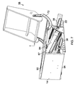
図3の図面はさらに、足置きの支持動作機構の一部を図示している。図6に示す足置き台14は、支持動作機構の様々な部分を詳しく明らかにするように、図3から省略されている。足置き台14は、以下で詳しく記載されているように、足置き板機構78に回動するよう連結され、この足置き板機構78は左右の横側面パネル12の内向きの面それぞれに固定された斜めのガイドトラック80上を引き出しのように摺動する。ガイドトラック80の位置は、可動の足置き板78がない図4および5の図面により明確に図示されている。斜めのガイド80は、板がガイド80の向きおよび傾きによって規定されるような斜めの並進運動に従動するよう制約する。係合手段(図示せず)が板78の外側エッジそれぞれに沿って設けられ、ガイド80と係合する。ガイド80は好適には金属、最適には鋼材で構成され、板78は重量を削減するために82で波形のMDFが好ましい。
The drawing of FIG. 3 further illustrates a portion of the footrest support operating mechanism. The
一対のいわゆる一定力ばね84が、椅子の内側領域から図3の86に示す方向に外側へと板78を付勢するために設けられている。この一定力ばねは、板78を方向86に外側へと展開するのに必要な駆動力を提供する。一定力ばね84はそれぞれ、巻きが戻ることに対して付勢された帯材のコイルを具え、これにより、ストリップの自由端がほどけたときに、ばねの付勢力が細長い帯の繰り出された部分を巻きいれるようになる。この種の構造は鋼材コイル型のテープメジャーなどの構成に使用されると当業者は理解されたい。本実施形態では、それぞれのコイル84は、足置き板の後部付近の上向き面に固定される。帯84の自由端は、それぞれの横側面パネル12の内向き面に固定される。コイル84は側面パネル12に近接する板78のエッジの近くに固定され、これにより、コイルから展開される帯の長さは実質的にパネル12と平行に延びる。従って、ばねの張力が、足載せ板78を外側へと方向86に作用させる。板78の移動範囲は、板が図3に示すような格納位置にある場合に表れる最大限に繰り出されたコイルばねの長さによって確定し、この板が複数の手段により保持される位置は以下に記載されている。従って、この板78は、開くように付勢されるが、当業者にはよく知られているようなラッチまたは他の保持手段によって格納位置または閉じた位置に格納もされる引き出し型の構造として機能する。
A pair of so-called constant force springs 84 are provided to bias the
前述したような足置き台14は、図6および7では格納位置に図示されている。図7では、横側面パネル12が図面から取り除かれ、椅子の支持動作機構の詳細を明らかにしている。図7では、一定力ばねの自由端87を明確に見ることができるが、当然ながら、この端部は、実際の機構では側面パネル12に固定されている。更なる詳細が図8の図面で明らかにされており、動作機構の内側を図示するために足置き台14が図面から取り除かれている。この図面では、足置き板78には下側に固定された一対のヒンジ90が設けられており、このヒンジの一部が板78の前縁に取り付けられていることが見て取れる。両ヒンジの他の部分は足置き台14の後面または下側に連結され、足置き台14を足置き板の前縁に回動可能に連結している。足置き台14は上縁92と下縁94の間の実質的に中間位置に回動するよう連結される。すなわち、上縁および下縁は、足置きが図6および7の図面に示すように格納されているときに椅子の通常の直立形態に規定される。図6に示す垂直形態からほぼ水平に展開された形態まで足置き台14を回動させることは、足置き台の上縁92と座部フレーム52、好適には図3および8に示す座部フレームの先端部材96との間に弾性材料を固定することにより実現する。ウェビングなど(図示せず)が座部フレームの前方で横断部材96に固定され、足置き台14の後部/下側の上縁92の領域に固定されてもよく、これにより、板78が前方へと移動して足置き台を展開すると、回転モーメントがウェビングまたは同様の材料の張力によって生成され、上縁92をその中心の回動軸周りに回転させる。上縁92と下縁94の間の中間点またはその近くで足置き台を回動させることにより、足置きの格納は、着座したユーザが踵で板の下縁94の領域に緩い力を加えることによって容易に実現しうると理解されたい。これにより足置き台が水平向きから斜めの向きに回転し、ユーザの下脚を更に下げると、着座したユーザの下脚の重量が一定力ばね84の付勢力に対して作用して、板を実質的に図7に示す位置へと格納する。
The
足置き台14は、図10に最もよく見られるように、ラッチ機構によって格納位置に保持される。
The
図10では、ラッチ機構98は、ピン(図示せず)を保持する足置き台14(図10には図示せず)の下側に装着されたブラケット100を有し、このピンは、クロス部材24(図10には図示せず)に固定されたブラケット104に装着されたラッチレバー102と係合する。ラッチ102は閉鎖位置に付勢され、足置き台14を図7に示すような格納位置にロックする。当該技術分野において知られているように、ラッチレバー102の遠隔操作は、ユーザによって、好適には椅子の側面から遠隔的に操作されるボーデンケーブル型の機構といったケーブルリリースによってもたらされる。
In FIG. 10, the
図示された実施形態によるリクライニング椅子では、足置きは椅子のリクライニング部分から独立して動作することができ、これにより、足置きは、格納された垂直位置から実質的に水平の位置まで、椅子のリクライニング運動から独立して展開することができる。この形態は多くの場合、「TV姿勢」と称される。動力型の実施形態では、第1に、椅子が「TV姿勢」に適応するように足置きを展開位置へと外側に駆動させるために単一の電気リニアアクチュエータが設けられてもよく、このアクチュエータの更なる拡張機能が、前述のガイドおよび回動機構により背もたれ支持部が従動した状態で、基部に対して中間支持部を前方且つ上方に駆動させる。これは、単一の線形アクチュエータが一端で基部構造の一部に固定され、他端で足置き、または図示された実施形態の足置き板78のような足置きの展開/格納機構に固定される動力型の実施形態において、容易に実現することができる。
In a reclining chair according to the illustrated embodiment, the footrest can operate independently from the reclining portion of the chair, so that the footrest can be moved from a stored vertical position to a substantially horizontal position. Can be deployed independently from the reclining movement. This form is often referred to as “TV attitude”. In the powered embodiment, first, a single electric linear actuator may be provided to drive the footrest outward to the deployed position so that the chair adapts to the “TV posture”, and this actuator This further expansion function drives the intermediate support portion forward and upward with respect to the base portion in a state where the backrest support portion is driven by the above-described guide and rotation mechanism. This is because a single linear actuator is secured at one end to a portion of the base structure and at the other end to a footrest or to a footrest deployment / retraction mechanism such as the
上記の説明は主に図3乃至6の図面を指しているが、図3乃至13の図面は同一の実施形態の様々な図面であって、図7の図面は、椅子の支持構造および動作機構の詳細を明らかにすべく横側面パネル12が取り除かれた図6の図面と類似している、ということを理解されたい。図7の図面では、ガイドスロット36および38は、取り除かれた側面パネルの対応した形状のスロット内に固定されるため概略的に図示されており、横側面パネルが存在しているように正しい位置に置かれて図示されていると理解されたい。図8では、前方の足置き台14を取り除くことで図7の図面がさらに変更され、それ故に椅子の更なる詳細が明らかとなっている。
Although the above description mainly refers to the drawings of FIGS. 3 to 6, the drawings of FIGS. 3 to 13 are various drawings of the same embodiment, and FIG. It should be understood that this is similar to the drawing of FIG. 6 with the
図9の図面では、(右側の)他の横側面パネル12が図8の図面から取り除かれているが、第2の2つの一定力ばね84を含む更なる詳細部が追加されている。 In the drawing of FIG. 9, the other lateral side panel 12 (on the right) has been removed from the drawing of FIG. 8, but with additional details including a second two constant force springs 84.
図10では、背支持部20を含む更なる詳細部が図面から取り除かれており、この実施形態では、組立式家具構造の技術ではよく知られている方法で運搬および保管のために背支持部を取り外しができるという点で、背支持部20は着脱可能に取り付けることができる。図10の図面では、ボード78だけではなく、座部フレーム支持部52も図面から取り除かれている。
In FIG. 10, additional details including the
図11の図面ではラッチ機構が取り除かれ、図12の図面では、足置き用のアクチュエータ機構が取り除かれており、これにより、ガイドスロット34および38と支持レバー72に関連する基礎支持部の主な構成要素のみが図示されている。
In the drawing of FIG. 11, the latch mechanism has been removed, and in the drawing of FIG. 12, the footrest actuator mechanism has been removed, so that the main support of the base support associated with the
図13は、図5に示すような椅子の右側にある、直立支持部30と、ローラベアリング48と、回動ピン74と、レバーアーム72とU字型のガイドスロット76の詳細部を含む、背もたれ支持部の運動をガイドする第2のガイド手段の詳細を拡大して図示している。
FIG. 13 includes details of an
図14を参照すると、本発明の第2の実施形態によるリクライニング椅子機構の一部を図示している。図14の図は、リクライニング椅子、ソファなどの支持動作機構の片側を図示しているという点で、図5に示すものと類似している。図14に示す機構の構成および動作の概略的な原理は、基礎支持部16と、中間支持部18と、背支持部20とが設けられているという点で、前述の実施形態と実質的に同一である。この実施形態では、L字型のシャーシ脚部22はスフィンクスのような形状を有する平面的な支持パネル110に置き換えられており、図14の図面に示すパネルの反対側には、図面の112、114および116に示す3カ所に3つのローラベアリングを保持している。116でパネルの反対側に回転可能に取り付けられたローラベアリング118は前述の実施形態のベアリング48と均等であるが、ガイド76の上縁部と係合する代わりに、ベアリング118は、側面パネル124に回転可能に連結された背支持アーム122の下部の湾曲面120によって係合している。この側面パネル124は中間支持部の一部を構成しており、前述の実施形態のパネル12と均等である。
Referring to FIG. 14, a part of a reclining chair mechanism according to a second embodiment of the present invention is illustrated. The view of FIG. 14 is similar to that shown in FIG. 5 in that one side of a support operation mechanism such as a reclining chair or sofa is shown. The general principle of the structure and operation of the mechanism shown in FIG. 14 is substantially the same as that of the above-described embodiment in that a
ここで図15a乃至15eを参照すると、特に図15aは、図14の125に示す方向に見た、図14の支持動作機構の側面図を示している。図15aの側面図では、側面パネル124が、前述の実施形態におけるガイドスロット36および38と均等である、一対の斜めに平行かつオフセットしたスロット126および128を具えていると理解されたい。ガイドスロット126は、114で基礎支持部材110に回転可能に取り付けられたローラベアリング130を収容する。ガイドスロット128は、112で支持部材110に回転可能に取り付けられたローラベアリング132を収容する。この点では、3つのローラベアリング118、130および132は、前述の実施形態におけるベアリング48、32および34とそれぞれ均等であると理解されたい。
Referring now to FIGS. 15a through 15e, in particular FIG. 15a shows a side view of the support operating mechanism of FIG. 14 as viewed in the direction indicated by 125 in FIG. In the side view of FIG. 15a, it will be appreciated that the
側面パネル124は、背支持アーム122の側面に回転可能に装着された一対のローラベアリング138、140を収容するラジアルスロット136を有する直立部分134をパネルの後部に有しているという点で、第1の実施形態の側面パネル12とは僅かに異なっている。従って、背支持アーム122は、スロット136の曲率中心と一致する軸を中心に中間支持パネル124に対して回転する。
The
本発明の第2の実施形態の支持動作機構は特に、MDFまたは同様の高強度の低コスト材料といった板材から製造するのに適している。この基礎支持部材110は、CNCで形状を機械加工した板などから製造されることが好ましく、その後に適所にローラベアリングが取り付けられる。同様に平面状の側面パネル124もガイドスロット等を有するようにCNC機械加工によって製造されることが好ましい。背支持アーム122もこの方法で製造されることが好ましい。リクライニング椅子は、椅子の座部の幅によって決定される距離だけ離れた、図14に示す2つのこのような支持動作機構を有していると理解されたい。好適な実施形態では、中間支持パネル124は、内側の基礎支持部材110に対して椅子の外側に配置されるが、複数の実施形態では、基礎支持部110が外側にあり中間支持パネル124が内側にある状態が想定される。
The support operating mechanism of the second embodiment of the present invention is particularly suitable for manufacturing from plate material such as MDF or similar high strength low cost material. The
図15a乃至15eは、図15aの完全に直立した位置から、図15dの完全にリクライニングした位置まで、図15b、cおよびeに示す中間位置と共に様々な位置にある図14の支持動作機構を示している。本発明の第1の実施形態のように、背支持アームが下方に回動したときに、回動軸周りの背支持アームの動作が、基部に対して直線的に上方かつ前方方向への中間支持部の動作と連動するように、3つの主な支持部である基部、中間部および背もたれが連動する。第2の実施形態におけるリクライニング椅子の支持動作機構の動作は、ベアリング118およびガイド面120に発生した反力が、第1の実施形態について前述したように中間支持部を前方かつ上方に駆動させるという点で、第1の実施形態のものと実質的に類似している。
15a to 15e show the support operating mechanism of FIG. 14 in various positions with the intermediate position shown in FIGS. 15b, c and e from the fully upright position of FIG. 15a to the fully reclined position of FIG. 15d. ing. As in the first embodiment of the present invention, when the back support arm rotates downward, the operation of the back support arm around the rotation shaft is linearly upward and forward intermediate with respect to the base. The base part, the middle part, and the backrest, which are the three main support parts, are interlocked so as to be interlocked with the operation of the support part. The operation of the support operation mechanism of the reclining chair in the second embodiment is that the reaction force generated in the
図15a乃至15eに示す運動は、図16aの完全に直立した位置から、徐々に図16dに示す完全にリクライニングした位置まで図16a乃至16dの支持動作機構を反対側から図示している。 The movement shown in FIGS. 15a to 15e illustrates the support operating mechanism of FIGS. 16a to 16d from the fully upright position of FIG. 16a to the fully reclining position of FIG. 16d from the opposite side.
ここで図17a乃至17cの一連の詳細な斜視図を参照すると、椅子の後部近傍の第2のガイド手段の領域の詳細な機構を図示しており、背支持アーム122がローラベアリング118によって軸を中心に支持されている。カム型のガイド面120の形状および湾曲が、互いおよび基礎支持部110の双方に対する可動部122および124の相対的な運動を決定する。ガイド面120の湾曲は、ガイドスロット76のように、背支持部が回動運動する際に十分な反力がベアリング118とガイド面120の間に存在するように決定され、背支持部の下方への回動運動は、ガイドスロット126、128およびそれぞれのベアリング130および132によって決定されるように、中間支持部を前方かつ上方に移動させる。ガイド面120の湾曲は、ガイドスロット76および特に上縁80も同様に、記載した支持動作機構が正確に機能するためには重要であると理解されたい。
Referring now to the series of detailed perspective views of FIGS. 17a-17c, the detailed mechanism of the region of the second guide means near the rear of the chair is illustrated, with the
図17a乃至17cは、リクライニング椅子が直立形態(図17a)、リクライニング形態(図17b)および中間位置(図17c)にあるときの支持動作機構の各部分を図示している。 Figures 17a to 17c illustrate the portions of the support operating mechanism when the reclining chair is in the upright configuration (Fig. 17a), the reclining configuration (Fig. 17b) and the intermediate position (Fig. 17c).
調整可能なリクライニング椅子用の支持動作機構10の更なる実施形態が図18−21に図示されている。図18−21の実施形態は図3乃至13の実施形態と実質的に同一であり、以下に詳しく記載するように足置き支持部および動作機構に変更を加えている。図3−13および18−21の図面では、同一の参照番号が同一の構成部品に使用されている。
A further embodiment of a
図18は、本発明の第3の実施形態による支持動作機構10の後方上部からの斜視図である。図19は、図18の支持動作機構の後方からの斜視図であり、明確にするため左側面パネルと足置きパネルが省略されている。図18乃至21の支持動作機構のリクライニング部分は、図3乃至13の実施形態を参照して上述したものと実質的に同一である。支持動作機構の足置き部分が異なっている。図18の図面に見られるように、足置き台またはパネルは、椅子の両側面に設けられた一対の細長い弓形の取付アームに回動するよう連結されている。このパネル14は、上縁92と下縁94の間の実質的に中間地点でアーム140に回動するよう連結されており、アーム140とパネル14の間の回動連結部はパネル14の平面の各開口部142に設けられている。この方法では、パネルの回動軸はパネル平面に位置し、好適にはパネルの前平面と後平面の間のパネルの中心に位置する。これは、図18に示す形態のようなパネルの最も遠い拡張した半分に僅かな量の力を適用する動作で着座したユーザによって回動軸を中心に容易に回転させることができる平衡した足置きを設けているため、足置きの展開および格納という点では有利であり、着座したユーザの踵の動作によってパネルを回転させる僅かな回転モーメントを作りだし、次いで以下に詳しく説明するように格納する。
FIG. 18 is a perspective view from the upper rear side of the
弓形の取付アームは、各側面パネル12の間の支持動作機構10の対向する側面に互いに平行に位置している。これらのアーム140は、その長さに沿って様々な位置で管状クロス部材144、146および148によって互いに連結され、剛体のフレーム構造を提供する。この剛体のフレーム構造は、図3乃至13の第1の実施形態における可動の足置き板78と均等と見なすことができると理解されたい。足置き板78と同様に、剛体のフレーム構造はブラケット80’において側面パネル12に対して運動するよう装着されており、この実施形態では、ブラケット80’には各アーム140の対応する湾曲ガイド凹部152と係合する湾曲フランジ150が設けられ、足置き板の格納位置と展開位置の間の曲線経路に沿ってアームをガイドする。
The arcuate mounting arms are positioned parallel to each other on opposite sides of the
図18の図面に最もよく見られるように、足置きを外側に展開位置へと付勢するためガスストラット154が設けられている。このガスストラットは、一端(図示せず)で中間支持構造18の一部に固定され、伸長した端部でコード156に連結されており、このコードは、足置きパネル14から最も遠い各アーム140の端部における2つの固定点158の間にガスストラットによる張力下で保持されている。ガスストラット154およびコード156は、図3乃至13の実施形態における一定力のコイルばね84と均等とみなすことができる。ガスストラット154の付勢力に対して足置きを格納(垂直)位置に保持すべく、リリースキャッチ(図示せず)が図3乃至13の第1の実施形態のリリースキャッチと同様に設けられており、このキャッチは前述した当該技術分野で知られているようなボーデンケーブルによって解放される。
As best seen in the drawing of FIG. 18, a
ここで図20および21を参照すると、図20の直立の(リクライニングしていない)TV姿勢では、足置き台14が前述した足置き動作機構によって外側且つ上方に展開されている。図21は、74の回動軸を中心に背もたれ支持部20を回転させることにより半分リクライニングした位置に移動した椅子のフレームを示しており、側面パネル12を含む中間支持部18をスロット36、38によって規定された経路に沿って基部に対して上方且つ前方に移動させている。この前方への構成要素の運動は、いわゆる「ゼロ壁」機能を提供する。
Referring now to FIGS. 20 and 21, in the upright (not reclining) TV posture of FIG. 20, the
ここで図22乃至24を参照すると、本発明の第4の実施形態によるリクライニング椅子機構の一部を図示している。図22乃至24に示す機構の構造および動作の概略的な原理は、基礎支持部16、中間支持部18および背支持部(図示せず)が設けられているという点で、前述の実施形態と実質的に同一であり、前述の実施形態の同一または類似する構成要素を示すため、同一の参照番号が図22乃至24の図面に使用されている。第4の実施形態は、第2の実施形態のように、第1および第3の実施形態のL型シャーシ脚部22が第2の実施形態の中間支持部の支持パネルに類似した平面状の支持パネル110と置き換えられているという点で、実質的に第1および第2の実施形態の複合型であると理解されたい。第4の実施形態では、パネル110は、図中の112、114および116に示す三カ所に3つのローラベアリングを保持している。116でパネルの側面に回転可能に装着されたローラベアリング118は2部分に設けられる、すなわち、2つのローラベアリング要素が同一のシャフトまたはピンに与えられ、これにより2つのベアリング要素が116において同軸上に整列している。ベアリング要素の一方118a(図中の陰影線によって、隠れた詳細部として示される)は第1および第3の実施形態のベアリング48と均等であり、背もたれのブラケット72の各ガイド76の上縁80と係合し、第2のベアリング要素(図示せず)はパネル110の第3のガイドスロット160と係合し、第3のガイドスロットおよび第2のベアリング要素は、スロット126、128とベアリング130、132を含む上記の第1のガイド手段の部分を具え、第3のスロット160は他の2つのスロット126、128と平行にパネルに配置される。図面に見られるように、図3乃至13および18乃至22の実施形態を参照して前述したように、背もたれの支持ブラケット72は、ピン74によってパネルに回動するよう装着されている。図22乃至24の実施形態では、中間支持部の側面パネル124は基礎支持パネル110の内側に配置されているが、基礎支持パネルが中間支持パネルの内側にある実施形態も想定されると理解されたい。
With reference now to FIGS. 22-24, a portion of a reclining chair mechanism according to a fourth embodiment of the present invention is illustrated. The general principles of the structure and operation of the mechanism shown in FIGS. The same reference numerals are used in the drawings of FIGS. 22 to 24 to indicate the same or similar components of the previous embodiments that are substantially the same. In the fourth embodiment, as in the second embodiment, the L-shaped
本発明の第5の実施形態は、図25乃至36に示す調整可能なベッド210を具えている。
The fifth embodiment of the present invention comprises an
本発明の実施形態は更に調整可能なベッドを含む。 Embodiments of the invention further include an adjustable bed.
図25乃至36は、本発明の第5の実施形態による調整可能なベッド200を概略的に図示している。このベッド200は、調整可能な背支持部202と、固定された中央支持部204と、調整可能な上脚支持部206と下脚支持部208とを具えている。
Figures 25 to 36 schematically illustrate an
図25乃至27、図31および32では、背支持部202、中央支持部204および脚支持部206、208が下降した状態の降下形態にあるベッド200が図示されており、近接する支持部分が基礎支持部210の上に実質的に平らに載っている。これらの支持部202、204、206、208は、それぞれ近接するマットレス支持クッションまたはパッド220、222、224、226を支持するそれぞれ隣接する平らな平面パネル212、214、216、218を具え、これらを組み合わせて適切なマットレス(図示せず)を上に支持するマットレスの支持土台を設け、いわゆる「ソフトエッジ」の調整可能なベッドを提供する。ベッド200はダブルベッドだが、本実施形態は標準的なシングルサイズのベッドから更に大きいダブルを含む、多くの異なる幅のベッドを意図している。
25 to 27, 31 and 32, the
図26に最もよく図示されているように、基礎支持部210は板型の材料によって構成されたほぼ長方形のフレームを具えており、この材料は産業用樹脂、MDF、材木または他の繊維型板などであってもよい。基礎支持フレーム210は、クロス部材パネル232、234によってそれぞれの端部付近で互いに連結された一対の細長い横側面パネル228、230を有し、長方形の箱形の構造支持フレームを形成している。基礎支持フレーム210はベッド200の床置き部分を構成しており、これについて支持フレームは、床の上に直接静置されてもよく、あるいは当該技術分野で既知のキャスター、脚部などを設けてもよい。
As best illustrated in FIG. 26, the
可動キャリッジ236の形態をした中間支持部が、体支持部202、204、206、208の下側の基礎支持フレーム210の内側領域内に取り付けられている。中間支持部236は図27および28の図中に最もよく見ることができ、体支持パネル212−218および関連するマットレス支持クッション220−226は明確にするために図面から省略されている。図27では、図示されたベッドの構成部分は、ベッドが通常の平らな形態に配置された状態で示されている。図28では、図示された部分は、ベッドが完全に直立した形態に配置された状態で図示されている。この中間支持キャリッジは、基礎支持フレームの左右の横側面パネル228、230と近接して配置された一対の細長い平行の側面パネル238、240を具えている。パネル238、240は対称的に同一であり、これによりベッドの片側の取付機構は他方と同一となる。これらのパネルは、ベッドの長さに沿って間隔が開けられた一対の平行なクロス部材242、244によって互いに堅く連結されている。パネル238、240は、家具業界に広く使用され、CNC機械加工に適しているようなMDFまたは産業用樹脂などの板材から構成されることが好ましい。クロス部材242、244は側面パネルと同一の材料から構成されてもよいが、以下により完全に記載されているように、様々な体部分を移動させるべく適用されたアクチュエータ荷重を支持するために、金属、好適には鋼材であってもよい。クロス部材242、244にはそれぞれ、その長さの中間点に各アクチュエータ取付ブラケット246が設けられる。
An intermediate support in the form of a
背支持パネル212は、当該支持パネル212の下側に取り付けられ、そこから延在している一対の荷重支持部材248によって、中間支持キャリッジに回動するよう装着されている。荷重支持部材248は、中間支持部の各側面パネル238、240に実質的に近接して、それらの内側に位置するように、間隔をあけてパネル212の横方向に離れて配置され、これにより、荷重支持部材248の側面に回転可能に取り付けられた回転要素ベアリング250a、250b、250c(図29、30および31)は、各パネル238、240の弓形スロット252それぞれに位置して、その中に係留して保持される。荷重支持部材248は、中間支持部に対して背もたれ支持部202を回動するよう装着する連結レバーを構成する。
The
上脚支持パネル216は同様に、支持パネル216の下側に取り付けられ、そこから延在している一対の荷重支持部材254によって中間支持キャリッジに回動するよう取り付けられている。荷重支持部材254は、中間支持部の各側面パネル238、240と実質的に近接して、それらの内側に位置するように、間隔をあけてパネル216の横方向に離れて配置され、これにより、荷重支持部材254の側面に回転可能に取り付けられた回転要素ベアリング256a、256b、256c(図29および30)は、各パネル238、240の弓形スロット258それぞれに位置して、その中に係留して保持される。
Similarly, the upper
中央部パネル214は、図25に示すようなベッドの降下形態における背支持パネル212と上脚支持パネル216の間に隣接して、中間支持キャリッジに対して固定される。下脚支持パネル218は、ヒンジ260により、それぞれ隣接しているエッジに沿って上脚支持パネル216に回動するよう連結されている。
The
荷重支持部材248および254は三日月形状を有する実質的な平面状であって、中間支持部の各側面パネル238、240と(数ミリメートル程度の小さいクリアランスで)実質的に同一平面に位置するよう設計されており、図26および27に示すようなベッドの降下形態における基礎支持キャリッジの枠の範囲内では、パネル212−218は基礎支持フレーム210の上辺の上に実質的に平らに、あるいはその上に単に載っている。荷重支持部材248、254にはそれぞれ、支持部材の平面に対して垂直に延在する、内側に突出した平面要素266が設けられて、各パネル212および216の下側と係合し、それに固定される取付部材を提供している。
The
荷重支持部材248はクロス部材262によって互いに堅く連結され、同様に荷重支持部材254はクロス部材264によって互いに連結される。クロス部材262、264にはそれぞれ、各線形アクチュエータ(図示せず)の一端に連結するため、長さの中間点にアクチュエータ取付ブラケット268が設けられている。
The
図29の図中に最もよく見られるように、各荷重支持部材248には、中間支持キャリッジの近接する側面パネルに面する支持部材の側面に配置された、回転要素ベアリング250a、250b、250cが設けられている。ベアリング250aおよび250bは類似した構造であり、荷重支持部材の表面から突出した直立ピンに装着される単一の回転要素ベアリングを具えている。第3のベアリング250cは、長いピン上に同軸に整列した一対のベアリング要素250c’および250c”を具えている点でわずかに異なっている。この配置は図30のベアリング250cの平面図に更に図示されており、最も外側のベアリング要素250c”は、荷重支持部材から第1のベアリング要素250c’の約2倍の距離に位置している。ベアリング250a、250bおよび250cは、図26−28の図面に示す支持部材248の反対側の270a、270bおよび270cに示す位置に配置される。
As best seen in the view of FIG. 29, each
荷重支持部材254のベアリングの配置は、3つのベアリング256a、256bおよび256c全てが250aおよび250bのような単一要素型であって、図26−28の支持部材の逆側に示すような位置272a、272bおよび272cにそれぞれ配置されるという点を除き、支持部材248に関して上述された配置と類似している。
The bearing arrangement of the
ベッドの両側には、支持部材の運動がスロット258内のベアリングの運動によって制約されるように、ベアリング256a、256bおよび256cがスロット258内に配置されている。これは、スロット258の曲率中心によって規定された回動軸、およびスロットの長さおよびスロット内のベアリング要素256aおよび256cの離隔によって決定される移動範囲について、パネル216ひいては上脚支持部206に中間支持部を基準とした回動運動をもたらす。支持部材254の回動運動の範囲は、スロット258の両端、およびベアリングのそれぞれ1つがスロットの各端部と接合することによる各ベアリング256aおよび256cの離隔によって規定される。ベアリング256aおよび256cは、湾曲したスロット258の約半分の長さに対応する最大距離まで間隔が開いてもよい。
On both sides of the bed,
同様に、ベアリング250a、250bおよび250c’はスロット252に配置され、これにより支持部材の運動はスロット252内のベアリングの運動によって制約される。これは、スロット252の曲率中心によって規定された回転軸、およびスロットの長さおよびスロット内のベアリング要素250aおよび250c’の離隔よって決定される移動範囲について、パネル212ひいては背支持部202に中間支持部を基準とした回転運動をもたらす。支持部材248の回動運動の範囲は、スロット252の両端、およびベアリングのそれぞれ1つがスロットの各端部と接合することによる各ベアリング250aおよび250c’の離隔によって規定される。ベアリング250aおよび250c’は、湾曲したスロット252の約半分の長さに対応する最大距離まで間隔が開いてもよい。
Similarly,
スロット252および258の位置は図31の図中で最もよく見ることができ、ベッドの調整機構をより詳しく図示すべく明確にするために、側面パネル228は省略されている。中間支持部のパネル228の一方のみが図31の側面図に図示されているが、パネル228、230は実質的に互いに同一であって、前述のような支持ベアリング250a−c’および256a−cを収容するための一対の湾曲したガイドスロット252、258をそれぞれ有していると理解されたい。第1のガイドスロット252はパネル228の後方半分に設けられ、第2のスロット258はパネルの前方半分に設けられる。第2のスロット258の曲率中心274は近接するマットレス支持クッション222、224の隣接エッジに位置し、これにより使用時に様々な位置間でベッドを調整しても、隣接エッジの領域にある支持クッションの上に位置するマットレスを圧縮させない。同様に、第1のスロット252の曲率中心276は、隣接するマットレス支持クッション220、222の隣接エッジに位置し、これにより使用時に様々な位置間でベッドを調整しても、隣接エッジの領域にある支持クッションの上に位置するクッションまたはマットレスを圧縮させない。
The location of
ベッドが降下形態にあるときのベアリング要素250a−cおよび256a−cの位置が図31の図面に示されており、前方スロット258の後端にベアリング256cが、後方スロット252の前端にベアリング250aが位置している。
The position of bearing
ベアリング要素250a−cおよび256a−cの位置は図32の図面にも図示されており、さらに詳細を示すべく側面パネル240も取り除かれている。この図では、前方および後方のスロットの位置がスロットインサート252’および258’によって表されており、これらのインサートは側面パネル240があるかのように本来の位置に図示されている。インサート252’および258’はベアリング要素250a−c’および256a−cに対する耐摩耗性のベアリング表面を提供し、中間支持キャリッジの各側面パネルにおける適切なサイズのスロットに嵌合し、上述の実施形態のスロットインサート32、38と同様に機能する。図32の図中では、降下形態にあるベッドについて、スロット252および258と荷重支持部材248、254の相対位置を見ることができる。図32の側面図は、荷重支持部材254の前端における角度が付いた接合面278を含む、荷重支持部材248および254の形状をより明確に図示しており、この接合面の目的は以下に詳しく記載する。
The locations of the
図31および32の図面は更に、中間支持キャリッジが基礎支持部210に対して可動して取り付けられるように図示している。各側面パネル238、240には、各パネルの長さに沿って間隔を開けた位置に配置され、各パネルの表面から直立し、基礎支持部の近接する外側パネル228、230の方へと突出しているベアリングピンに装着された3つの回転要素ベアリング280a−cが設けられており、各スロットインサート282a’−c’を受けるべくベアリング係合スロット282a−cが設けられている。インサート282a’−c’が装着される側面パネル240は図示するために省略されているが、これらのインサート282a’−c’は、図31および32の図のそれぞれ本来の位置に図示されている。インサート282a’−c’は、各側面パネル228、230の内向きの面に設けられたブラインドスロットに配置される。後方のスロットインサート282c’の一部は図26の図中に見ることができ、前方のスロットインサート282a’の一部は図33の図中に見ることができる。
31 and 32 further illustrate that the intermediate support carriage is movably attached to the
スロット282a−c及び対応するインサート282a’−c’は直線的であって、パネル228、230の長さに沿って整列しており、様々な位置の間でベッドを調整する際に、中間支持キャリッジを基礎支持部に対して斜めではない直線的な平行方向に誘導する。スロットおよびインサートは実質的に同一であり、ベッドの中央部に沿ってほぼ等間隔に離れている。スロット280a−cは、パネル228、230の側面に開口部を作らないという点で眼には見えないが、各インサートおよび中間支持キャリッジに固定された回転要素ベアリング280a−cを収容できる程度の深さである。この機構は、本発明のこの実施形態に前述の第1のガイド手段を構成する。
第4のスロット284およびインサート284’の組み合わせは、後方の荷重支持部材248に取り付けられたベアリング要素250c”を収容するパネル228、230の後方付近に設けられている。この機構は、本実施形態に前述の第2のガイド手段を構成する。第4のスロット284は、第1および第2の湾曲部分286、288を有する曲線形である。第1の部分286はスロット252に対応する湾曲部を有し、ベッドが完全に降下した位置と図34の半分上昇した位置の間の位置にある場合にスロットの後方と一致する。この相対運動の範囲では、背支持部が図34の半分上昇した位置まで上昇するときにベアリング250c”は第1の部分286内を自由に移動し、スロットの曲率および方向が突然変化する。第2の部分288は第1の部分とは異なる曲率中心を有しており、パネル228、230の長さに沿って第1の部分よりもなだらかに上昇する。この曲率の変化はベアリング要素250c”とスロットの第2の部分288の間に反力を生成し、この反力は、回転モーメントが(アクチュエータの1つまたはそれ以外のものによって)ベッドの背支持部分に適用されると、ガイド280a−cに沿って中間支持キャリッジを基礎支持部に対して前方に押し付ける。背支持部分が図34の中間位置を越えて上昇すると、ベアリング250c”がスロットの第2の部分に沿って移動するように押し進められ、ベアリング要素とスロット288の上面との反作用によって生成される抵抗が中間部を基礎支持部に対して前方に駆動させる。結果として得られる動作は、背もたれが移動する前述した実施形態の椅子機構の支持部と中間支持部分の相対運動に類似している。本実施形態では、ベッドの背支持部がベッドの直立形態となる背もたれを提供するように上昇した場合、この背支持部分が移動したときに同様の協働運動が起こる。従って、本実施形態に記載されたベッドはさらに、家具製品のゼロ壁としても機能する。これは、ユーザは家具等の横へのアクセスを保持することができ、背もたれが上昇または降下したときに家具に対するユーザの相対位置は変化せず、体支持部分が取り付けられる中間支持キャリッジの直線的な前方または後方運動によって運動が釣り合うため、調整可能なベッドの状況において特に有意である。
The combination of the
ベッドの形態が完全に降下した形態から完全に上昇した形態まで調整されたときのベッドの様々な部分の相対位置は、以下の図32(完全に降下)から、図34(半分上昇)、図35(半分上昇と完全に上昇の間の中間)、図36(完全に上昇)までの一連の図面のに見ることができる。各図面は図32のようなベッド構造の同じ部分の側面図を表しており、ベッドがある形態から別の形態に移動したときの各スロット内のベアリングの相対位置を図示している。 The relative position of the various parts of the bed when the bed configuration is adjusted from a fully lowered configuration to a fully elevated configuration is shown in FIG. 32 (fully lowered), FIG. 34 (half raised), FIG. 35 (intermediate between half rise and full rise), can be seen in the series of drawings up to FIG. 36 (full rise). Each drawing represents a side view of the same portion of the bed structure as in FIG. 32, illustrating the relative positions of the bearings in each slot as the bed moves from one configuration to another.
図示された実施形態では、図示された様々な位置にわたるベッドの運動は、クロス部材242上のブラケット246とクロス部材262上のブラケット268の間に連結された、背支持部202を動かすための第1のアクチュエータ(図示せず)と、クロス部材244上のブラケット246とクロス部材264上のブラケット268の間に連結された、脚支持部206を動かすための第2の線形アクチュエータ(図示せず)とを含む、調整可能な家具の機構に広く利用される2の線形電気式アクチュエータによって行われる。ベッド200の下側における線形アクチュエータジャックの相対位置は特に有意であると当業者は理解するであろう。その理由は、第1に、アクチュエータの両端は前述の各ブラケットに回動するよう連結されているため、アクチュエータによって適用される力のベクトルが実際には荷重支持パネルが移動するときのその動作に追従するためであり、第2に、アクチュエータによって生成される回転モーメントが適用される各回動軸274、276まで、力のベクトルは常に著しい距離オフセットしており、それ故に多くの機械的な利点を有する動力機構を提供するためである。
In the illustrated embodiment, the movement of the bed across the various illustrated positions is the first to move the
図32および34の図面を比較することで最もよく見られるように、各荷重支持部材254の端部にある角度が付いた接合面278は、パネル216と218の間のヒンジ連結部260での回動運動の範囲を制限するように機能する。支持部材が274の回動軸を中心に回転し始めると部分208および206の両方が上昇し始めるが、接合面278がパネル218の下側と係合して図34の位置に達するまでヒンジが開く。これは、肢の上部または下部の快適な相対位置が最初に得られるまでユーザの下脚が上がらない場合に、有用な「膝の故障用」機能を提供する。
As best seen by comparing the drawings of FIGS. 32 and 34, the
Claims (34)
前記背支持部は前記中間支持部に対して回動運動するよう取り付けられ、前記第1および第2のガイド手段は、使用時の前記中間支持部に対する前記背支持部の回動が前記中間支持部を前記基礎支持部に対して動かすように配置され、
前記背支持部がレバー機構の少なくとも一部を提供し、その回動運動がさらに前記基礎支持部に対して前記中間支持部を動かし、
前記第2のガイド手段は背支持部の回動中心から間隔をおいて配置されることを特徴とする家具。 In adjustable furniture comprising a base support, an intermediate support and a back support, the intermediate support is guided to move relative to the base support by a first guide means and the back support The portion is guided by a second guide means so as to move relative to both the base support portion and the intermediate support portion, and the second guide means is at least connected to one of the base support portion and the back support portion. A curved line having one guide portion and at least one driven portion connected to the other of the foundation support portion and the back support portion, and the guide portion of the second guide means has one or more curved portions. Is in shape ;
The back support portion is attached so as to rotate with respect to the intermediate support portion, and the first and second guide means are configured so that the rotation of the back support portion relative to the intermediate support portion in use is the intermediate support. Arranged to move the part relative to the foundation support ,
The back support provides at least a portion of a lever mechanism, and its rotational movement further moves the intermediate support relative to the base support;
The furniture characterized in that the second guide means is disposed at a distance from the center of rotation of the back support portion .
34. The furniture according to claim 32 or 33 , wherein the first and second guide means are provided on both sides of the bed so that adjustable parts are supported and guided by the guide means on both sides of the bed. Furniture characterized by being.
Applications Claiming Priority (5)
| Application Number | Priority Date | Filing Date | Title |
|---|---|---|---|
| GB0914436.1 | 2009-08-18 | ||
| GB0914436A GB0914436D0 (en) | 2009-08-18 | 2009-08-18 | Adjustable furniture |
| GB0918685.9 | 2009-10-23 | ||
| GBGB0918685.9A GB0918685D0 (en) | 2009-10-23 | 2009-10-23 | Adjustable furniture |
| PCT/GB2010/001565 WO2011021002A2 (en) | 2009-08-18 | 2010-08-18 | Adjustable furniture |
Publications (2)
| Publication Number | Publication Date |
|---|---|
| JP2013502255A JP2013502255A (en) | 2013-01-24 |
| JP5763639B2 true JP5763639B2 (en) | 2015-08-12 |
Family
ID=42938152
Family Applications (1)
| Application Number | Title | Priority Date | Filing Date |
|---|---|---|---|
| JP2012525201A Expired - Fee Related JP5763639B2 (en) | 2009-08-18 | 2010-08-18 | Adjustable furniture |
Country Status (16)
| Country | Link |
|---|---|
| US (2) | US9241571B2 (en) |
| EP (1) | EP2467044B1 (en) |
| JP (1) | JP5763639B2 (en) |
| CN (1) | CN102686129B (en) |
| AU (1) | AU2010284834B2 (en) |
| BR (1) | BR112012003558A2 (en) |
| CA (1) | CA2774433C (en) |
| DK (1) | DK2467044T3 (en) |
| ES (1) | ES2544729T3 (en) |
| GB (3) | GB2472920B (en) |
| IN (1) | IN2012DN02203A (en) |
| MX (1) | MX2012002037A (en) |
| MY (1) | MY159810A (en) |
| NZ (1) | NZ598420A (en) |
| WO (1) | WO2011021002A2 (en) |
| ZA (1) | ZA201202004B (en) |
Families Citing this family (68)
| Publication number | Priority date | Publication date | Assignee | Title |
|---|---|---|---|---|
| GB0708053D0 (en) | 2007-04-26 | 2007-06-06 | Leuven | Adjustable furniture |
| GB0918685D0 (en) | 2009-10-23 | 2009-12-09 | Integrated Furniture Technolog | Adjustable furniture |
| BR112012003558A2 (en) | 2009-08-18 | 2019-09-24 | Integrated Furniture Tech Limited | adjustable furniture item |
| GB201015084D0 (en) * | 2010-09-09 | 2010-10-27 | Integrated Furniture Technologies Ltd | Lift-recliner chair |
| US10004334B2 (en) | 2010-09-09 | 2018-06-26 | Integrated Furniture Technologies Limited | Lift-recliner chair |
| US9145072B2 (en) | 2010-11-24 | 2015-09-29 | Everett Sollars | Power disc style seat recliner |
| US8550559B2 (en) * | 2010-11-24 | 2013-10-08 | Everett Sollars | Power disc style seat recliner |
| JP5774883B2 (en) * | 2011-03-28 | 2015-09-09 | アトムメディカル株式会社 | Medical table |
| WO2013062423A2 (en) * | 2011-10-25 | 2013-05-02 | Wayne Smeaton Manson | Bed chair |
| GB201211027D0 (en) * | 2012-06-21 | 2012-08-01 | Fletcher Richard | Lifting units |
| EP2956106B1 (en) * | 2013-02-18 | 2022-01-05 | Mascull, Roger Thomas and Mascull, Elizabeth Jocelyn as trustees of the RT and EJ Mascull Family Trust | A backrest angle adjustment system on a seat for a physically disabled person |
| JP6186613B2 (en) * | 2013-02-22 | 2017-08-30 | 株式会社タカギセイコー | Chair |
| GB2518394A (en) | 2013-09-20 | 2015-03-25 | Sherborne Upholstery Ltd | Adjustable bed |
| GB2520253A (en) * | 2013-11-12 | 2015-05-20 | Integrated Furniture Technologies Ltd | Adjustable bed |
| US9635943B2 (en) * | 2014-03-28 | 2017-05-02 | L&P Property Management Company | Wall-proximity reclining mechanism with consistent-height seat |
| DE102014115126A1 (en) * | 2014-07-18 | 2016-01-21 | Deon Group AG | Electromotive adjustable support device |
| DE102014115033A1 (en) * | 2014-07-18 | 2016-01-21 | Deon Group AG | Electromotive adjustable support device |
| CN107205551B (en) * | 2014-12-11 | 2020-09-25 | 德沃特奥金有限公司 | Adjustable furniture |
| GB201504140D0 (en) | 2015-03-11 | 2015-04-22 | Motus Mechanics Ltd | Adjustable bed |
| GB201610212D0 (en) | 2016-06-13 | 2016-07-27 | Motus Mech Ltd | Adjustable bed |
| WO2017003518A1 (en) * | 2015-06-29 | 2017-01-05 | Zodiac Seats Us Llc | Ramp mount |
| US10092106B2 (en) * | 2015-07-14 | 2018-10-09 | La-Z-Boy Incorporated | Recliner and legrest mechanism for a furniture member |
| US10021979B2 (en) * | 2016-02-22 | 2018-07-17 | John Hart Miller | Rotating and non-rotating reclining chairs with tilting mechanisms |
| US10959894B2 (en) * | 2016-03-03 | 2021-03-30 | Stryker Corporation | Patient support apparatus with actuator feedback |
| WO2017176902A1 (en) * | 2016-04-05 | 2017-10-12 | Pride Mobility Products Corporation | Seat positioning system for a wheelchair |
| WO2018035363A1 (en) * | 2016-08-17 | 2018-02-22 | Durden Allan Fitzgerald | Pillow lifting system |
| US9986835B2 (en) | 2016-09-22 | 2018-06-05 | La-Z-Boy Incorporated | Furniture member having cam tilt mechanism |
| CN106617880A (en) * | 2016-11-17 | 2017-05-10 | 嘉兴意合机电有限公司 | Manual adjustable chair system |
| CN106617858A (en) * | 2016-11-17 | 2017-05-10 | 嘉兴意合机电有限公司 | Electric adjustable seat system for old people |
| CN106617835A (en) * | 2016-11-17 | 2017-05-10 | 嘉兴意合机电有限公司 | Dual-motor electric adjustable seat |
| CN117678866A (en) | 2017-02-10 | 2024-03-12 | 高登科技公司 | Reclining chair or lifting reclining chair with changeable lifting posture |
| US10485347B2 (en) | 2017-02-24 | 2019-11-26 | L&P Property Management Company | All-linkage recline mechanism for high leg seating units |
| US10390621B2 (en) * | 2017-02-24 | 2019-08-27 | L&P Property Management Company | Modular assembly for high leg row seating |
| US10383443B2 (en) * | 2017-02-24 | 2019-08-20 | L&P Property Management Company | Modular assembly for high leg row seating |
| US10213020B2 (en) * | 2017-02-24 | 2019-02-26 | L&P Property Management Company | Modular assembly for high leg row seating |
| US10568428B2 (en) | 2017-04-07 | 2020-02-25 | La-Z-Boy Incorporated | Furniture member having flexible seatback |
| US10537178B2 (en) | 2017-04-07 | 2020-01-21 | La-Z-Boy Incorporated | Furniture member having flexible seatback |
| IT201700079483A1 (en) * | 2017-07-14 | 2019-01-14 | Malvestio S P A | BED STRUCTURE FOR DEGENCE |
| CN107319816A (en) * | 2017-07-26 | 2017-11-07 | 广州视源电子科技股份有限公司 | Foldable handrail and seat |
| US10537177B2 (en) | 2017-09-20 | 2020-01-21 | La-Z-Boy Incorporated | Furniture member with adjustable seat depth |
| US10285502B2 (en) | 2017-09-20 | 2019-05-14 | La-Z-Boy Incorporated | Furniture member with adjustable seat height |
| US10561244B2 (en) | 2017-09-20 | 2020-02-18 | La-Z-Boy Incorporated | Furniture member with recline and tilt |
| US10492613B2 (en) | 2017-09-20 | 2019-12-03 | La-Z-Boy Incorporated | Legrest mechanism for furniture member |
| US10874222B2 (en) | 2017-09-22 | 2020-12-29 | Ashley Furniture Industries, Inc. | Ready to assemble furniture |
| NO343925B1 (en) * | 2017-10-20 | 2019-07-08 | Ekornes Asa | Sit Module |
| MX2020004234A (en) * | 2017-10-25 | 2020-07-22 | L&P Property Man Co | Modular assembly for high leg row seating. |
| TWI667000B (en) * | 2018-03-22 | 2019-08-01 | 漢翔航空工業股份有限公司 | Chair back linkage seat disk mechanism |
| US10524575B2 (en) | 2018-04-16 | 2020-01-07 | La-Z-Boy Incorporated | Furniture member with foldable pawl and ratchet assembly |
| USD889864S1 (en) | 2018-05-14 | 2020-07-14 | Bombardier Inc. | Lounge chair |
| EP3569503A1 (en) | 2018-05-14 | 2019-11-20 | Bombardier Inc. | Lounge chair for aircraft |
| US10524574B2 (en) | 2018-05-18 | 2020-01-07 | La-Z-Boy Incorporated | Furniture member with powered wall-proximity mechanism |
| US10820708B2 (en) | 2018-05-18 | 2020-11-03 | La-Z-Boy Incorporated | Furniture member with wall-proximity mechanism and locking trigger |
| GB201813009D0 (en) | 2018-08-09 | 2018-09-26 | Eevolv Ltd | A drive mechanism |
| US10632031B2 (en) * | 2018-08-21 | 2020-04-28 | Pride Mobility Products Corporation | Adjustable lift chair frame |
| CN109247745A (en) * | 2018-10-24 | 2019-01-22 | 中源家居股份有限公司 | A kind of slide rail type sofa |
| CN109171305A (en) * | 2018-10-24 | 2019-01-11 | 中源家居股份有限公司 | It is a kind of can any adjusting angle of backrest sofa |
| GB201901010D0 (en) * | 2019-01-24 | 2019-03-13 | Eevolv Ltd | Lay-flat chair |
| US11259641B2 (en) | 2019-01-25 | 2022-03-01 | L&P Property Management Company | Synchronization of motion furniture with multiple actuators |
| DE202019101920U1 (en) * | 2019-04-03 | 2020-07-06 | Innotec Motion GmbH | Seating furniture chassis |
| WO2020227658A1 (en) | 2019-05-09 | 2020-11-12 | La-Z-Boy Incorporated | Reclining chaise |
| US20210177679A1 (en) * | 2019-12-16 | 2021-06-17 | Stryker Corporation | Patient support with lift assembly |
| CN111568103B (en) * | 2020-05-21 | 2022-04-08 | 海宁高点家具有限公司 | Massage sofa |
| CN116157043A (en) | 2020-07-22 | 2023-05-23 | 佛姆维家具有限公司 | Chair |
| US11197549B1 (en) | 2020-09-28 | 2021-12-14 | La-Z-Boy Incorporated | Wall-proximity furniture member having sync mechanism |
| CN114451728B (en) * | 2020-11-10 | 2024-03-22 | 博格睿(重庆)科技有限公司 | Multifunctional sofa |
| US20220248862A1 (en) * | 2021-02-11 | 2022-08-11 | Hhc Changzhou Corporation | Ready to assemble structural system for a bed |
| EP4340679A1 (en) * | 2021-05-17 | 2024-03-27 | Remacro Machinery & Technology (Wujiang) Co., Ltd. | Mechanical extension apparatus for extendable seat and extendable seat |
| TWI803397B (en) * | 2022-07-21 | 2023-05-21 | 施權航 | electric bed |
Family Cites Families (81)
| Publication number | Priority date | Publication date | Assignee | Title |
|---|---|---|---|---|
| DE7302408U (en) * | 1973-08-30 | Hess E | Adjustable bed, reclining furniture or the like | |
| US638466A (en) * | 1899-09-30 | 1899-12-05 | J A Kelly & Bros Inc | Sofa-bedstead. |
| US912214A (en) | 1908-07-18 | 1909-02-09 | Lloyd W Ward | Invalid-bed. |
| GB191322022A (en) * | 1913-09-30 | 1914-08-20 | Albert Tyzack | Improvements in or connected with Reclining Chairs having Adjustable Seats and Backs. |
| GB101239A (en) * | 1916-02-15 | 1916-08-31 | Albert Glenister | Improvements in or relating to Chairs, Couches or the like. |
| US1238078A (en) * | 1916-06-06 | 1917-08-28 | Harvey N Ault | Adjustable chair. |
| GB173772A (en) | 1921-01-04 | 1922-12-14 | Albert Edwin Gell | Improvements in reclining adjustable chairs and seats |
| GB329834A (en) * | 1929-05-17 | 1930-05-29 | Abraham Hart | Improvements in or relating to chairs, seats and the like |
| GB414464A (en) | 1933-03-28 | 1934-08-09 | H J Searle & Son Ltd | Improvements in and relating to adjustable chairs and settees |
| US2400588A (en) * | 1943-11-19 | 1946-05-21 | Reconstruction Finance Corp | Seat |
| GB775679A (en) | 1954-06-15 | 1957-05-29 | Greaves & Thomas Ltd | Improvements in and relating to reclining chairs |
| US2954072A (en) * | 1956-07-17 | 1960-09-27 | Fossati Mario | Hinged rods mechanism for reclinable armchairs |
| US3086814A (en) * | 1959-06-15 | 1963-04-23 | Anton Lorenz | Reclining chair of the multiple movement type |
| DE1404651C3 (en) * | 1959-09-17 | 1975-07-24 | Fridtjof F. 1000 Berlin Schliephacke | Reclining armchair with swiveling leg support |
| US3202453A (en) * | 1963-07-09 | 1965-08-24 | Ford Motor Co | Retractable seat |
| US3269767A (en) * | 1963-10-18 | 1966-08-30 | Marzocchi Lorenzo | Folding-frame chair |
| US3369767A (en) | 1965-09-27 | 1968-02-20 | Greenfield Company | Seat belt retractor |
| US3873152A (en) | 1974-01-09 | 1975-03-25 | John Garas | Adjustable orthopedic lounger |
| FR2527061B1 (en) * | 1982-05-19 | 1985-11-15 | Ami | ARTICULATED SEAT |
| EP0107882B1 (en) * | 1982-10-28 | 1986-07-23 | FLIGHT EQUIPMENT & ENGINEERING LIMITED | Vehicle seats |
| DE3440634C2 (en) | 1984-11-07 | 1986-09-11 | J.M. Voith Gmbh, 7920 Heidenheim | Device for double-sided coating of moving webs |
| US5197781A (en) * | 1988-07-18 | 1993-03-30 | Hirofumi Tada | Reclining apparatus |
| JPH0289947U (en) * | 1988-12-28 | 1990-07-17 | ||
| US4996731A (en) | 1989-04-19 | 1991-03-05 | Kruyt Robert A | Adjustable bed |
| US5246266A (en) * | 1990-09-18 | 1993-09-21 | Chairworks Taiwan Limited | Chair |
| DE4135948C2 (en) * | 1991-10-31 | 1993-12-23 | Rolf Voelkle | Chair, in particular office swivel chair |
| DE4224458A1 (en) * | 1992-07-24 | 1994-01-27 | Brose Fahrzeugteile | Seat cushion adjustment for vehicle seat - has mechanical drive providing movement between two extreme positions |
| NO300754B1 (en) * | 1994-10-14 | 1997-07-21 | Handicare Ind As | Adjustable chair |
| GB9425078D0 (en) * | 1994-12-13 | 1995-02-08 | British Airways Plc | A seating unit |
| JP3605161B2 (en) | 1994-12-21 | 2004-12-22 | シロキ工業株式会社 | Reclining device |
| US5640730A (en) | 1995-05-11 | 1997-06-24 | Maxwell Products, Inc. | Adjustable articulated bed with tiltable head portion |
| JPH08308680A (en) * | 1995-05-17 | 1996-11-26 | Tenryu Ind Co Ltd | Leg rest for vehicle seat |
| IT1282278B1 (en) * | 1995-12-29 | 1998-03-16 | Bortoluzzi Mobili Srl | BED WITH SUPPORT PLATFORM WITH RECLINING SECTIONS USING A SEMI-AUTOMATIC MANUALLY OPERATED MECHANISM |
| DE19711944C2 (en) * | 1997-03-21 | 2000-08-31 | Girsberger Holding Ag Buetzber | Vehicle seat |
| US5897462A (en) * | 1997-04-18 | 1999-04-27 | St. Germain; Robert J. | Exercise apparatus |
| DE59806685D1 (en) | 1997-07-16 | 2003-01-30 | Huelsta Werke Huels Kg | Bed slatted frame with adjustable grate parts |
| DE29715343U1 (en) | 1997-08-27 | 1997-11-27 | Unimet Zentrallager Nord Gmbh | Seating furniture, in particular garden armchairs |
| JPH11244096A (en) * | 1998-03-06 | 1999-09-14 | Tsunayoshi Morikawa | Reclining bed with waist sliding mechanism |
| DE19906547B4 (en) * | 1999-02-17 | 2004-03-25 | Innovint Einrichtungs Gmbh | Child seat for mobile use in an aircraft |
| IT1306152B1 (en) * | 1999-06-02 | 2001-05-30 | Aviointeriors Spa | ARMCHAIR WITH PERFECTED CRADLE MOVEMENT, IN PARTICULAR AIRCRAFT. |
| AU9137401A (en) * | 2000-11-18 | 2002-05-23 | Moon Ho Choi | Safety device for car seat |
| GB0101239D0 (en) | 2001-01-17 | 2001-02-28 | 3M Innovative Properties Co | Medicinal aerosols |
| JP2003199641A (en) * | 2001-01-25 | 2003-07-15 | Hirobumi Tada | Reclining device |
| AU2002248713A1 (en) * | 2001-03-27 | 2002-10-08 | Hill-Rom Services, Inc. | Hospital bed |
| CA2625107C (en) * | 2001-08-09 | 2009-11-03 | Virgin Atlantic Airways Limited | A seating system and a passenger accomodation unit for a vehicle |
| JP4902070B2 (en) * | 2001-08-22 | 2012-03-21 | コンビ株式会社 | child seat |
| DE10152227C2 (en) * | 2001-10-20 | 2003-10-09 | Sichelschmidt Stanzwerk | seating |
| ES2192476B2 (en) * | 2002-01-18 | 2004-06-01 | Sebastian Aramburu Echevarria | RECLINING ARMCHAIR. |
| US20030172455A1 (en) * | 2002-03-18 | 2003-09-18 | Roma John K. | Spring-assisted futon frame |
| US6739661B1 (en) * | 2002-07-15 | 2004-05-25 | David N. Dukes | Pivotable reclining child safety car seat |
| ITMI20022194A1 (en) * | 2002-10-16 | 2004-04-17 | Icf Spa | CHAIR WITH SEAT AND FURNITURE BACK. |
| GB0325358D0 (en) | 2003-10-30 | 2003-12-03 | Peter Cook Internat Plc | Powered furniture |
| GB2409607A (en) | 2003-12-23 | 2005-06-29 | Symbian Ltd | Caller ID using a movie clip |
| GB2415759B (en) | 2004-06-29 | 2007-06-13 | Newfrey Llc | A threaded insert |
| US7325265B2 (en) | 2004-07-30 | 2008-02-05 | Hill-Rom Services, Inc. | Advanced articulation system and mattress support for a bed |
| JP2008509790A (en) | 2004-08-16 | 2008-04-03 | ヒル−ロム サービシーズ,インコーポレイティド | Chair |
| GB0422205D0 (en) | 2004-10-07 | 2004-11-03 | Arthurs Alfred W | Chair incorporating mechanism to assist rising |
| DE102005016943B4 (en) * | 2005-04-12 | 2006-11-30 | Stanzwerk Wetter Sichelschmidt Gmbh & Co. Kg | Ottoman |
| MY144523A (en) * | 2005-08-18 | 2011-09-30 | Itoki Corp | Chair having a unit to move a lumbar support |
| JP4934146B2 (en) * | 2005-11-21 | 2012-05-16 | ナイトギア エルエルシー | Seat assembly |
| US7585018B2 (en) * | 2006-01-10 | 2009-09-08 | La-Z-Boy Incorporated | Wall proximity reclining chair with in-line linkage mechanism |
| US7455360B2 (en) | 2006-04-21 | 2008-11-25 | L & P Property Management | Seating furniture with lift mechanism |
| WO2008004583A1 (en) * | 2006-07-07 | 2008-01-10 | Maruichi Selling Inc. | Reclining chair structure |
| US7703851B2 (en) * | 2006-09-21 | 2010-04-27 | Mazda Motor Corporation | Seat device |
| US7445279B2 (en) * | 2006-11-13 | 2008-11-04 | L & P Property Management Company | Pivot-over-arm reclining mechanism for a seating unit |
| US7766421B2 (en) * | 2006-12-21 | 2010-08-03 | L & P Property Management Company | Recliner lift chair with power lift and reclining units |
| GB0704546D0 (en) * | 2007-03-08 | 2007-04-18 | Contour Premium Aircraft Seati | Adjustable seat |
| DE102007024218A1 (en) * | 2007-05-11 | 2008-11-13 | Appeltshauser, Georg, Dipl.-Ing. | Seating furniture e.g. armchair, has head element adjustable as whole in height relative to seat part, where head element is adjustable by guide along carrier for head element, and guide runs curvedly in adjustment direction of head element |
| US7641277B2 (en) | 2008-01-02 | 2010-01-05 | L & P Property Management Co. | Zero-wall clearance linkage mechanism for a high-leg seating unit |
| US20090178201A1 (en) | 2008-01-15 | 2009-07-16 | L&P Property Management Company | Adjustable Bed Having Movable Lumbar Support |
| TW201002242A (en) * | 2008-07-09 | 2010-01-16 | Joy Ride Tech Co Ltd | Fitness lounge chair |
| GB0918685D0 (en) | 2009-10-23 | 2009-12-09 | Integrated Furniture Technolog | Adjustable furniture |
| BR112012003558A2 (en) | 2009-08-18 | 2019-09-24 | Integrated Furniture Tech Limited | adjustable furniture item |
| US8226162B2 (en) * | 2009-09-11 | 2012-07-24 | Campbell Corey A | Child safety seat |
| DE102010014126B4 (en) | 2010-04-07 | 2011-11-10 | Ferdinand Lusch Gmbh & Co. Kg | Seating furniture with a seat pivotable in a standing-up assistance position |
| US8403415B2 (en) * | 2010-08-16 | 2013-03-26 | Be Aerospace, Inc. | Aircraft passenger seat recline mechanism |
| GB201015084D0 (en) | 2010-09-09 | 2010-10-27 | Integrated Furniture Technologies Ltd | Lift-recliner chair |
| US10004334B2 (en) | 2010-09-09 | 2018-06-26 | Integrated Furniture Technologies Limited | Lift-recliner chair |
| US8534758B2 (en) * | 2010-09-13 | 2013-09-17 | Tropitone Furniture Co., Inc. | Reclinable seating apparatus and method |
| WO2014183112A2 (en) | 2013-05-10 | 2014-11-13 | L & P Property Management Company | Linkage mechanism for hi-leg seating unit |
| CN107087394B (en) | 2014-10-14 | 2019-08-02 | 马尔韦斯蒂奥股份公司 | Bed for being hospitalized |
-
2010
- 2010-08-18 BR BR112012003558A patent/BR112012003558A2/en not_active IP Right Cessation
- 2010-08-18 ES ES10749893.3T patent/ES2544729T3/en active Active
- 2010-08-18 DK DK10749893.3T patent/DK2467044T3/en active
- 2010-08-18 JP JP2012525201A patent/JP5763639B2/en not_active Expired - Fee Related
- 2010-08-18 CN CN201080046829.5A patent/CN102686129B/en active Active
- 2010-08-18 NZ NZ598420A patent/NZ598420A/en not_active IP Right Cessation
- 2010-08-18 EP EP20100749893 patent/EP2467044B1/en active Active
- 2010-08-18 AU AU2010284834A patent/AU2010284834B2/en not_active Ceased
- 2010-08-18 CA CA2774433A patent/CA2774433C/en active Active
- 2010-08-18 GB GB1013879.0A patent/GB2472920B/en active Active
- 2010-08-18 GB GB1308695.4A patent/GB2501993B/en active Active
- 2010-08-18 GB GB1120973.1A patent/GB2486335A/en not_active Withdrawn
- 2010-08-18 MX MX2012002037A patent/MX2012002037A/en active IP Right Grant
- 2010-08-18 US US13/390,985 patent/US9241571B2/en active Active
- 2010-08-18 WO PCT/GB2010/001565 patent/WO2011021002A2/en active Application Filing
- 2010-08-18 MY MYPI2012000719A patent/MY159810A/en unknown
-
2012
- 2012-03-14 IN IN2203DEN2012 patent/IN2012DN02203A/en unknown
- 2012-03-16 ZA ZA2012/02004A patent/ZA201202004B/en unknown
-
2015
- 2015-12-16 US US14/971,231 patent/US10405660B2/en active Active
Also Published As
| Publication number | Publication date |
|---|---|
| BR112012003558A2 (en) | 2019-09-24 |
| US9241571B2 (en) | 2016-01-26 |
| AU2010284834A1 (en) | 2012-03-15 |
| CA2774433C (en) | 2018-10-23 |
| DK2467044T3 (en) | 2015-06-29 |
| GB201120973D0 (en) | 2012-01-18 |
| AU2010284834B2 (en) | 2016-01-07 |
| GB201013879D0 (en) | 2010-09-29 |
| MX2012002037A (en) | 2012-09-07 |
| GB201308695D0 (en) | 2013-06-26 |
| EP2467044A2 (en) | 2012-06-27 |
| US20120193946A1 (en) | 2012-08-02 |
| EP2467044B1 (en) | 2015-05-13 |
| ZA201202004B (en) | 2012-11-28 |
| ES2544729T3 (en) | 2015-09-03 |
| CN102686129B (en) | 2015-12-02 |
| GB2472920A (en) | 2011-02-23 |
| WO2011021002A3 (en) | 2011-05-26 |
| GB2501993B (en) | 2014-04-16 |
| CN102686129A (en) | 2012-09-19 |
| US10405660B2 (en) | 2019-09-10 |
| CA2774433A1 (en) | 2011-02-24 |
| WO2011021002A2 (en) | 2011-02-24 |
| IN2012DN02203A (en) | 2015-08-21 |
| GB2501993A (en) | 2013-11-13 |
| US20160120315A1 (en) | 2016-05-05 |
| GB2472920B (en) | 2014-02-05 |
| MY159810A (en) | 2017-02-15 |
| NZ598420A (en) | 2014-02-28 |
| GB2486335A (en) | 2012-06-13 |
| JP2013502255A (en) | 2013-01-24 |
Similar Documents
| Publication | Publication Date | Title |
|---|---|---|
| JP5763639B2 (en) | Adjustable furniture | |
| EP2490574B1 (en) | Adjustable furniture | |
| AU641262B2 (en) | Chaise lounge reclining chair | |
| US5217276A (en) | Chair mechanism | |
| US8438676B2 (en) | Seating unit convertible to bed | |
| US9642468B2 (en) | Seating unit convertible to bed | |
| US5011220A (en) | Chair mechanism | |
| US7681945B1 (en) | Wall-avoiding convertible ottoman | |
| AU670469B2 (en) | Two-way high-leg recliner | |
| EP2981195B1 (en) | Seating unit convertible to bed | |
| IL99795A (en) | Chair mechanism |
Legal Events
| Date | Code | Title | Description |
|---|---|---|---|
| A621 | Written request for application examination |
Free format text: JAPANESE INTERMEDIATE CODE: A621 Effective date: 20130718 |
|
| A131 | Notification of reasons for refusal |
Free format text: JAPANESE INTERMEDIATE CODE: A131 Effective date: 20140701 |
|
| A601 | Written request for extension of time |
Free format text: JAPANESE INTERMEDIATE CODE: A601 Effective date: 20141001 |
|
| A602 | Written permission of extension of time |
Free format text: JAPANESE INTERMEDIATE CODE: A602 Effective date: 20141008 |
|
| A601 | Written request for extension of time |
Free format text: JAPANESE INTERMEDIATE CODE: A601 Effective date: 20141031 |
|
| A602 | Written permission of extension of time |
Free format text: JAPANESE INTERMEDIATE CODE: A602 Effective date: 20141110 |
|
| A601 | Written request for extension of time |
Free format text: JAPANESE INTERMEDIATE CODE: A601 Effective date: 20141201 |
|
| A602 | Written permission of extension of time |
Free format text: JAPANESE INTERMEDIATE CODE: A602 Effective date: 20141208 |
|
| A521 | Written amendment |
Free format text: JAPANESE INTERMEDIATE CODE: A523 Effective date: 20141226 |
|
| TRDD | Decision of grant or rejection written | ||
| A01 | Written decision to grant a patent or to grant a registration (utility model) |
Free format text: JAPANESE INTERMEDIATE CODE: A01 Effective date: 20150512 |
|
| A61 | First payment of annual fees (during grant procedure) |
Free format text: JAPANESE INTERMEDIATE CODE: A61 Effective date: 20150611 |
|
| R150 | Certificate of patent or registration of utility model |
Ref document number: 5763639 Country of ref document: JP Free format text: JAPANESE INTERMEDIATE CODE: R150 |
|
| LAPS | Cancellation because of no payment of annual fees |