JP5758354B2 - Wireless communication system - Google Patents
Wireless communication system Download PDFInfo
- Publication number
- JP5758354B2 JP5758354B2 JP2012150810A JP2012150810A JP5758354B2 JP 5758354 B2 JP5758354 B2 JP 5758354B2 JP 2012150810 A JP2012150810 A JP 2012150810A JP 2012150810 A JP2012150810 A JP 2012150810A JP 5758354 B2 JP5758354 B2 JP 5758354B2
- Authority
- JP
- Japan
- Prior art keywords
- base station
- unit
- path
- identification information
- route
- Prior art date
- Legal status (The legal status is an assumption and is not a legal conclusion. Google has not performed a legal analysis and makes no representation as to the accuracy of the status listed.)
- Active
Links
- 230000006854 communication Effects 0.000 title claims description 125
- 238000004891 communication Methods 0.000 title claims description 125
- 238000005259 measurement Methods 0.000 claims description 79
- 230000004044 response Effects 0.000 claims description 78
- 230000005540 biological transmission Effects 0.000 claims description 40
- 238000012546 transfer Methods 0.000 claims description 20
- 238000012508 change request Methods 0.000 claims description 12
- 238000010586 diagram Methods 0.000 description 26
- 238000012986 modification Methods 0.000 description 17
- 230000004048 modification Effects 0.000 description 17
- 238000004590 computer program Methods 0.000 description 16
- 230000006870 function Effects 0.000 description 7
- 230000000694 effects Effects 0.000 description 6
- CIWBSHSKHKDKBQ-JLAZNSOCSA-N Ascorbic acid Chemical compound OC[C@H](O)[C@H]1OC(=O)C(O)=C1O CIWBSHSKHKDKBQ-JLAZNSOCSA-N 0.000 description 3
- 230000001276 controlling effect Effects 0.000 description 3
- 230000011664 signaling Effects 0.000 description 3
- 230000007175 bidirectional communication Effects 0.000 description 2
- 230000008859 change Effects 0.000 description 2
- 238000005516 engineering process Methods 0.000 description 2
- 230000007774 longterm Effects 0.000 description 2
- 238000000034 method Methods 0.000 description 2
- 230000009471 action Effects 0.000 description 1
- 238000006243 chemical reaction Methods 0.000 description 1
- 238000013461 design Methods 0.000 description 1
- 238000009434 installation Methods 0.000 description 1
- 238000012545 processing Methods 0.000 description 1
- 230000001105 regulatory effect Effects 0.000 description 1
- 230000008054 signal transmission Effects 0.000 description 1
Images


Classifications
-
- H—ELECTRICITY
- H04—ELECTRIC COMMUNICATION TECHNIQUE
- H04W—WIRELESS COMMUNICATION NETWORKS
- H04W88/00—Devices specially adapted for wireless communication networks, e.g. terminals, base stations or access point devices
- H04W88/16—Gateway arrangements
-
- H—ELECTRICITY
- H04—ELECTRIC COMMUNICATION TECHNIQUE
- H04W—WIRELESS COMMUNICATION NETWORKS
- H04W76/00—Connection management
- H04W76/10—Connection setup
-
- H—ELECTRICITY
- H04—ELECTRIC COMMUNICATION TECHNIQUE
- H04W—WIRELESS COMMUNICATION NETWORKS
- H04W36/00—Hand-off or reselection arrangements
- H04W36/0005—Control or signalling for completing the hand-off
- H04W36/0083—Determination of parameters used for hand-off, e.g. generation or modification of neighbour cell lists
- H04W36/0085—Hand-off measurements
-
- H—ELECTRICITY
- H04—ELECTRIC COMMUNICATION TECHNIQUE
- H04W—WIRELESS COMMUNICATION NETWORKS
- H04W36/00—Hand-off or reselection arrangements
- H04W36/0005—Control or signalling for completing the hand-off
- H04W36/0083—Determination of parameters used for hand-off, e.g. generation or modification of neighbour cell lists
- H04W36/00835—Determination of neighbour cell lists
-
- H—ELECTRICITY
- H04—ELECTRIC COMMUNICATION TECHNIQUE
- H04W—WIRELESS COMMUNICATION NETWORKS
- H04W40/00—Communication routing or communication path finding
- H04W40/02—Communication route or path selection, e.g. power-based or shortest path routing
-
- H—ELECTRICITY
- H04—ELECTRIC COMMUNICATION TECHNIQUE
- H04W—WIRELESS COMMUNICATION NETWORKS
- H04W76/00—Connection management
- H04W76/20—Manipulation of established connections
- H04W76/22—Manipulation of transport tunnels
-
- H—ELECTRICITY
- H04—ELECTRIC COMMUNICATION TECHNIQUE
- H04W—WIRELESS COMMUNICATION NETWORKS
- H04W24/00—Supervisory, monitoring or testing arrangements
- H04W24/10—Scheduling measurement reports ; Arrangements for measurement reports
-
- H—ELECTRICITY
- H04—ELECTRIC COMMUNICATION TECHNIQUE
- H04W—WIRELESS COMMUNICATION NETWORKS
- H04W88/00—Devices specially adapted for wireless communication networks, e.g. terminals, base stations or access point devices
- H04W88/08—Access point devices
- H04W88/085—Access point devices with remote components
Landscapes
- Engineering & Computer Science (AREA)
- Computer Networks & Wireless Communication (AREA)
- Signal Processing (AREA)
- Mobile Radio Communication Systems (AREA)
Description
本発明は、無線通信システムに関する。 The present invention relates to a wireless communication system.
3GPP(Third Generation Partnership Project)規格に従う様々な無線通信システムが活用されている。3GPPに規定されるLTE/SAE(Long Term Evolution / System Architecture Evolution)規格に従う無線通信システムにおいては、ユーザデータの通信に使用される論理的な通信経路(ユーザプレーン経路(Uプレーン経路))が、サービングゲートウェイ(Serving Gateway)及び基地局であるeNB(evolved Node B)を経由してパケットゲートウェイ(PDN Gateway)とユーザ装置とに確立される。ユーザ装置は、確立されたUプレーン経路を用いて外部ネットワーク(インターネット等)との通信を実行することが可能である。 Various wireless communication systems complying with 3GPP (Third Generation Partnership Project) standards are used. In a wireless communication system in accordance with LTE / SAE (Long Term Evolution / System Architecture Evolution) standard defined in 3GPP, a logical communication path (user plane path (U-plane path)) used for user data communication is A packet gateway (PDN Gateway) and a user apparatus are established via a serving gateway and a base station eNB (evolved Node B). The user apparatus can execute communication with an external network (such as the Internet) using the established U-plane path.
より詳細には、パケットゲートウェイとユーザ装置とに確立されるUプレーン経路(EPSベアラ)は、パケットゲートウェイとサービングゲートウェイとに確立されるUプレーン経路(S5/S8ベアラ)、サービングゲートウェイと基地局(eNB)とに確立されるUプレーン経路(S1−Uベアラ)、及び基地局(eNB)とユーザ装置とに確立されるUプレーン経路(データ無線ベアラ)を含む。以上のUプレーン経路の制御(確立、変更、解放等)は、交換局であるMME(Mobile Management Entity)の主導の下に実行され得る。例えば、S1−Uベアラは、そのS1−Uベアラの端点となるサービングゲートウェイ及び基地局(eNB)を交換局が制御する(すなわち、制御プレーン経路(Cプレーン経路)を介して、交換局がサービングゲートウェイ及び基地局と制御信号を送受信する)ことにより確立される。 More specifically, the U plane path (EPS bearer) established between the packet gateway and the user equipment is the U plane path (S5 / S8 bearer) established between the packet gateway and the serving gateway, the serving gateway and the base station ( e-plane) and U-plane path (data radio bearer) established between the base station (eNB) and the user equipment. The above U-plane path control (establishment, change, release, etc.) can be executed under the leadership of an MME (Mobile Management Entity) as an exchange. For example, an S1-U bearer controls a serving gateway and a base station (eNB) serving as end points of the S1-U bearer (that is, the switching station serves via a control plane path (C plane path)). Established by transmitting and receiving control signals to and from the gateway and base station.
以上の無線通信システムが、eNBに加えて新たな種別の基地局を備えることを想定する。想定される新たな種別の基地局は、eNBが接続するのとは異なるサービングゲートウェイに接続することが可能である。また、想定される新たな種別の基地局の一部は交換局に対するCプレーン経路を有さない。したがって、交換局がサービングゲートウェイと従来の基地局(eNB)とに確立されるUプレーン経路の制御を実行する従来の無線通信システムによれば、以上のような新たな種別の基地局を備えるシステム構成を実現することが困難である。 It is assumed that the above wireless communication system includes a new type of base station in addition to the eNB. An assumed new type of base station can be connected to a different serving gateway from which the eNB is connected. Also, some of the assumed new types of base stations do not have a C-plane path to the switching center. Therefore, according to the conventional wireless communication system in which the switching center executes control of the U-plane path established between the serving gateway and the conventional base station (eNB), a system including the above new types of base stations It is difficult to realize the configuration.
以上の事情を考慮して、本発明は、新たな種別の基地局を備える無線通信システムを実現することを目的とする。 In view of the above circumstances, an object of the present invention is to realize a wireless communication system including a new type of base station.
本発明の無線通信システムは、ユーザ装置と、前記ユーザ装置と無線通信可能な複数の基地局と、複数のサービングゲートウェイと、ユーザデータ信号を伝送する経路であって前記基地局と前記サービングゲートウェイとに設定される論理経路であるユーザプレーン経路を制御する交換局とを備え、前記複数の基地局には、制御信号を伝送する経路であって前記交換局に対して設定される論理経路である制御プレーン経路を有する第1基地局と、前記交換局に対する制御プレーン経路を有さない第2基地局とが含まれ、前記ユーザ装置は、各基地局から受信した無線信号の受信品質に関する測定情報と前記各測定情報に対応する基地局の識別情報とを含む報告情報を、無線接続中の第1基地局に報告する報告部を備え、前記第1基地局は、複数の第2基地局の識別情報を記憶する基地局リストを記憶する記憶部と、前記ユーザ装置から報告された前記測定情報に基づいて、当該測定情報に対応する基地局を1つの端点とするユーザプレーン経路を設定すべきか否かを判定する経路設定判定部と、前記ユーザ装置から報告された前記識別情報に基づいて、当該識別情報に対応する基地局が第2基地局であるか否かを前記基地局リストを用いて判定する基地局判定部とを備える。 The wireless communication system of the present invention includes a user apparatus, a plurality of base stations capable of wireless communication with the user apparatus, a plurality of serving gateways, a path for transmitting a user data signal, and the base station and the serving gateway And a switching center that controls a user plane path that is a logical path set to the plurality of base stations, a path that transmits a control signal to the plurality of base stations and is a logical path that is set for the switching station A first base station having a control plane path and a second base station not having a control plane path for the exchange are included, and the user apparatus measures measurement information related to reception quality of a radio signal received from each base station And a report unit that reports report information including base station identification information corresponding to each measurement information to the first base station that is wirelessly connected. A storage unit that stores a base station list that stores identification information of the second base station, and a user who has one base point corresponding to the measurement information based on the measurement information reported from the user apparatus Based on the identification information reported from the user apparatus, whether or not the base station corresponding to the identification information is the second base station, based on the identification information reported from the user apparatus. A base station determination unit that determines using the base station list.
本発明の好適な態様において、前記第1基地局は、前記経路設定判定部が前記ユーザプレーン経路を設定すべきと判定した場合であって、前記ユーザプレーン経路の1つの端点となるべき基地局が第2基地局であると前記基地局判定部が判定したときに、前記交換局に対し、前記制御プレーン経路を介して、前記ユーザプレーン経路を設定することを要求する経路設定要求を送信する経路設定要求部を備え、前記交換局は、前記経路設定要求が設定することを要求する前記ユーザプレーン経路の別の端点となるサービングゲートウェイを選択するゲートウェイ選択部を備える。 In a preferred aspect of the present invention, the first base station is a base station that is to be set as one end point of the user plane path when the path setting determination unit determines that the user plane path should be set. When the base station determination unit determines that is a second base station, a path setting request is transmitted to the switching center for requesting setting of the user plane path via the control plane path. A path setting request unit; and the switching center includes a gateway selection unit that selects a serving gateway serving as another end point of the user plane path that is requested to be set by the path setting request.
本発明の好適な態様において、前記第1基地局の前記記憶部が記憶する前記基地局リストは、第2基地局の識別情報と、当該識別情報に対応する第2基地局を1つの端点とするユーザプレーン経路の別の端点となるサービングゲートウェイの識別情報とを対応付けて記憶し、前記第1基地局は、前記経路設定判定部が前記ユーザプレーン経路を設定すべきと判定した場合であって、前記ユーザプレーン経路の1つの端点となるべき基地局が第2基地局であると前記基地局判定部が判定したときに、前記ユーザプレーン経路の別の端点となるサービングゲートウェイを、前記基地局リストを用いて選択するゲートウェイ選択部と、前記第2基地局と、前記ゲートウェイ選択部が選択した前記サービングゲートウェイとに前記ユーザプレーン経路を設定することを要求する経路設定要求を、前記制御プレーン経路を介して前記交換局に送信する経路設定要求部とを備える。 In a preferred aspect of the present invention, the base station list stored in the storage unit of the first base station includes identification information of the second base station and a second base station corresponding to the identification information as one end point. This is a case where the first base station determines that the user plane route should be set by the route setting determination unit in association with the identification information of the serving gateway serving as another endpoint of the user plane route to be performed. When the base station determination unit determines that the base station that should be one end point of the user plane path is the second base station, a serving gateway that is another end point of the user plane path is The user plane route to the gateway selection unit selected using the station list, the second base station, and the serving gateway selected by the gateway selection unit Set path setting request which requests to, and a route setting request unit that transmits to the switching center via the control plane path.
本発明の好適な態様において、前記交換局は、前記基地局リストを生成する基地局リスト生成部と、生成された前記基地局リストを前記第1基地局に動的に送信する基地局リスト送信部とを備える。 In a preferred aspect of the present invention, the exchange station transmits a base station list that generates the base station list and a base station list that dynamically transmits the generated base station list to the first base station. A part.
本発明の他の無線通信システムは、ユーザ装置と、前記ユーザ装置と無線通信可能な複数の基地局と、複数のサービングゲートウェイと、ユーザデータ信号を伝送する経路であって前記基地局と前記サービングゲートウェイとに設定される論理経路であるユーザプレーン経路を制御する交換局とを備え、前記複数の基地局には、制御信号を伝送する経路であって前記交換局に対して設定される論理経路である制御プレーン経路を有する第1基地局と、前記交換局に対する制御プレーン経路を有さない第2基地局とが含まれ、前記ユーザ装置は、各基地局から受信した無線信号の受信品質に関する測定情報と前記各測定情報に対応する基地局の識別情報とを含む報告情報を、無線接続中の第1基地局に報告する報告部を備え、前記第1基地局は、前記ユーザ装置から報告された前記報告情報を、前記制御プレーン経路を介して前記交換局に送信する基地局送信部を備え、前記交換局は、複数の第2基地局の識別情報を記憶する基地局リストを記憶する記憶部と、前記ユーザ装置から報告された前記測定情報に基づいて、当該測定情報に対応する基地局を1つの端点とするユーザプレーン経路を設定すべきか否かを判定する経路設定判定部と、前記ユーザ装置から報告された前記識別情報に基づいて、当該識別情報に対応する基地局が第2基地局であるか否かを前記基地局リストを用いて判定する基地局判定部とを備える。 Another wireless communication system of the present invention includes a user apparatus, a plurality of base stations capable of wireless communication with the user apparatus, a plurality of serving gateways, and a path for transmitting a user data signal, the base station and the serving A switching center that controls a user plane path that is a logical path set to the gateway, and a logical path that is set to the switching station and that is a path for transmitting a control signal to the plurality of base stations A first base station having a control plane path and a second base station not having a control plane path for the exchange, and the user equipment relates to reception quality of a radio signal received from each base station A reporting unit for reporting report information including measurement information and base station identification information corresponding to each measurement information to a first base station that is wirelessly connected; A base station transmitter that transmits the report information reported from the user apparatus to the switching center via the control plane path, wherein the switching center stores identification information of a plurality of second base stations. Based on the measurement information reported from the user device, a storage unit that stores a station list, and a path for determining whether or not a user plane path with a base station corresponding to the measurement information as one endpoint should be set A base station determination that uses the base station list to determine whether the base station corresponding to the identification information is a second base station based on the identification information reported from the setting determination unit and the user apparatus A part.
本発明の好適な態様において、前記交換局は、前記経路設定判定部が前記ユーザプレーン経路を設定すべきと判定した場合であって、前記ユーザプレーン経路の1つの端点となるべき基地局が第2基地局であると前記基地局判定部が判定したときに、当該第2基地局を1つの端点とする前記ユーザプレーン経路の別の端点となるサービングゲートウェイを選択するゲートウェイ選択部を備える。 In a preferred aspect of the present invention, the exchange station determines that the route setting determination unit determines that the user plane route should be set, and the base station that is to be one end point of the user plane route is the first one. When the base station determination unit determines that there are two base stations, a gateway selection unit that selects a serving gateway serving as another endpoint of the user plane route having the second base station as one endpoint is provided.
本発明の別の無線通信システムは、ユーザ装置と、前記ユーザ装置と無線通信可能な複数の基地局と、複数のサービングゲートウェイと、ユーザデータ信号を伝送する経路であって前記基地局と前記サービングゲートウェイとに設定される論理経路であるユーザプレーン経路を制御する交換局とを備え、前記複数の基地局には、制御信号を伝送する経路であって前記交換局に対して設定される論理経路である制御プレーン経路を有する第1基地局と、前記交換局に対する制御プレーン経路を有さない第2基地局とが含まれ、前記ユーザ装置は、複数の第2基地局の識別情報を記憶する第1の基地局リストを記憶する記憶部と、各基地局から受信した無線信号の受信品質に関する測定情報を取得する測定情報取得部と、前記各測定情報に対応する基地局の識別情報を取得する識別情報取得部と、前記識別情報取得部が取得した前記識別情報に基づいて、当該識別情報に対応する基地局が第2基地局であるか否かを前記基地局リストを用いて判定する基地局判定部と、前記各測定情報と、当該測定情報に対応する基地局の前記識別情報と、当該識別情報に対応する基地局が第2基地局であるか否かを示す判定情報とを含む報告情報を、無線接続中の第1基地局に報告する報告部を備える。 Another wireless communication system of the present invention includes a user apparatus, a plurality of base stations capable of wireless communication with the user apparatus, a plurality of serving gateways, and a path for transmitting a user data signal, the base station and the serving A switching center that controls a user plane path that is a logical path set to the gateway, and a logical path that is set to the switching station and that is a path for transmitting a control signal to the plurality of base stations A first base station having a control plane path and a second base station not having a control plane path for the exchange, and the user apparatus stores identification information of a plurality of second base stations A storage unit that stores the first base station list, a measurement information acquisition unit that acquires measurement information related to the reception quality of the radio signal received from each base station, and the measurement information corresponding to each measurement information Based on the identification information acquired by the identification information acquisition unit acquired by the identification information acquisition unit and the identification information acquired by the identification information acquisition unit, it is determined whether the base station corresponding to the identification information is a second base station. A base station determination unit for determination using a station list, each of the measurement information, the identification information of the base station corresponding to the measurement information, and whether the base station corresponding to the identification information is a second base station A report unit that reports report information including determination information indicating to the first base station that is wirelessly connected.
本発明の好適な態様において、前記第1基地局は、前記ユーザ装置から報告された前記測定情報に基づいて、当該測定情報に対応する基地局を1つの端点とするユーザプレーン経路を設定すべきか否かを判定する経路設定判定部と、第2基地局の識別情報と、当該識別情報に対応する第2基地局を1つの端点とするユーザプレーン経路の別の端点となるサービングゲートウェイの識別情報と、を対応付ける第2の基地局リストを記憶する記憶部と、前記経路設定判定部が前記ユーザプレーン経路を設定すべきと判定した場合であって、前記ユーザ装置から報告された前記判定情報が、前記ユーザプレーン経路の1つの端点となるべき基地局が第2基地局であることを示すときに、前記ユーザプレーン経路の別の端点となるサービングゲートウェイを、前記第2の基地局リストを用いて選択するゲートウェイ選択部と、前記第2基地局と、前記ゲートウェイ選択部が選択した前記サービングゲートウェイとに前記ユーザプレーン経路を設定することを要求する経路設定要求を、前記制御プレーン経路を介して前記交換局に送信する経路設定要求部とを備える。 In a preferred aspect of the present invention, whether the first base station should set a user plane path having one base point corresponding to the measurement information based on the measurement information reported from the user apparatus A path setting determination unit that determines whether or not, identification information of a second base station, and identification information of a serving gateway serving as another end point of a user plane route having the second base station corresponding to the identification information as one end point And a storage unit that stores a second base station list that correlates to each other, and the route setting determination unit determines that the user plane route should be set, and the determination information reported from the user device is A serving gateway serving as another endpoint of the user plane path when indicating that a base station that is to be an endpoint of the user plane path is a second base station. Requesting that the user plane path is set to the gateway selection unit that selects the second base station list using the second base station list, the second base station, and the serving gateway selected by the gateway selection unit. A route setting request unit that transmits a route setting request to the exchange via the control plane route.
本発明の好適な態様において、前記第1基地局は、前記ユーザ装置から報告された前記報告情報を、前記制御プレーン経路を介して前記交換局に送信する基地局送信部を備え、前記交換局は、前記第1基地局から送信された前記報告情報に含まれる前記測定情報に基づいて、当該測定情報に対応する基地局を1つの端点とするユーザプレーン経路を設定すべきか否かを判定する経路設定判定部と、前記経路設定判定部が前記ユーザプレーン経路を設定すべきと判定した場合であって、前記報告情報に含まれる前記判定情報が、前記ユーザプレーン経路の1つの端点となるべき基地局が第2基地局であることを示すときに、前記ユーザプレーンの別の端点となるサービングゲートウェイを選択するゲートウェイ選択部とを備える。 In a preferred aspect of the present invention, the first base station includes a base station transmission unit that transmits the report information reported from the user apparatus to the switching center via the control plane path, and Determines, based on the measurement information included in the report information transmitted from the first base station, whether or not to set up a user plane route with one base point corresponding to the measurement information The route setting determination unit and the route setting determination unit determine that the user plane route should be set, and the determination information included in the report information should be one end point of the user plane route A gateway selection unit that selects a serving gateway serving as another end point of the user plane when the base station indicates the second base station.
本発明の好適な態様において、前記交換局は、前記第1の基地局リストを生成する基地局リスト生成部と、生成された前記第1の基地局リストを前記第1基地局を介して前記ユーザ装置に動的に送信する基地局リスト送信部とを備える。 In a preferred aspect of the present invention, the exchange station includes a base station list generation unit that generates the first base station list, and the generated first base station list via the first base station. And a base station list transmitter that dynamically transmits to the user apparatus.
本発明の好適な態様において、前記交換局は、前記ゲートウェイ選択部が選択した、前記ユーザプレーン経路の別の端点となる前記サービングゲートウェイに対し、前記サービングゲートウェイと前記第2基地局とに前記ユーザプレーンを設定することを指示する第1経路設定指示を送信する経路制御部を備え、前記サービングゲートウェイは、前記交換局からの前記第1経路設定指示の受信に応じて、当該サービングゲートウェイの識別情報を含む第1経路設定指示応答を前記交換局に送信する応答部を備え、前記交換局の前記経路制御部は、前記サービングゲートウェイからの前記第1経路設定指示応答の受信に応じて、前記サービングゲートウェイの前記識別情報を含む第2経路設定指示を、前記制御プレーン経路を介して前記第1基地局に送信し、前記第1基地局は、前記第2経路設定指示を前記第2基地局に転送する転送部を備え、前記第2基地局は、前記第1基地局から転送された前記第2経路設定指示に含まれる前記サービングゲートウェイの前記識別情報を用いて、上りリンクの前記ユーザプレーン経路を設定する経路設定部と、上りリンクの前記ユーザプレーン経路が設定された後に、当該第2基地局の識別情報を含む第2経路設定指示応答を前記第1基地局に送信する応答部とを備え、前記第1基地局の前記転送部は、前記第2経路設定指示応答を前記制御プレーン経路を介して前記交換局に転送し、前記交換局の前記経路制御部は、前記第1基地局からの前記第2経路設定指示応答の受信に応じて、前記第2基地局の前記識別情報を含む第3経路設定指示を前記サービングゲートウェイに送信し、前記サービングゲートウェイは、前記交換局から送信された前記第3経路設定指示に含まれる前記第2基地局の前記識別情報を用いて、下りリンクの前記ユーザプレーン経路を設定する経路設定部を備える。 In a preferred aspect of the present invention, the switching center selects the user to the serving gateway and the second base station with respect to the serving gateway that is another endpoint of the user plane route selected by the gateway selection unit. A path control unit that transmits a first path setting instruction that instructs to set a plane, and the serving gateway receives identification information of the serving gateway in response to reception of the first path setting instruction from the exchange A response unit that transmits a first path setting instruction response including the response to the switching center, wherein the path control unit of the switching center receives the first path setting instruction response from the serving gateway in response to receiving the first path setting instruction response. A second route setting instruction including the identification information of the gateway is sent to the first group via the control plane route. The first base station includes a transfer unit that transfers the second route setting instruction to the second base station, and the second base station transmits the second base station transferred from the first base station. A path setting unit configured to set the uplink user plane path using the identification information of the serving gateway included in the two path setting instruction; and after the uplink user plane path is set, the second base A response unit that transmits a second path setting instruction response including station identification information to the first base station, and the transfer unit of the first base station transmits the second path setting instruction response to the control plane path. The path control unit of the switching center transmits the identification information of the second base station in response to reception of the second path setting instruction response from the first base station. Including the third route setting instruction To the serving gateway, and the serving gateway sets the downlink user plane path using the identification information of the second base station included in the third path setting instruction transmitted from the exchange. A route setting unit.
本発明の好適な態様において、前記サービングゲートウェイの前記経路設定部は、下りリンクの前記ユーザプレーン経路が設定されると、第3経路設定指示応答を前記交換局に送信し、前記交換局の前記経路制御部は、前記第1基地局を介したユーザプレーン経路が確立されている場合に、前記第3経路設定指示応答の受信に応じて当該ユーザプレーン経路を解放すべきか否かを判定し、解放すべきと判定したときに、当該ユーザプレーン経路を解放するように前記第1基地局および自局を制御する。 In a preferred aspect of the present invention, when the downlink user plane route is set, the route setting unit of the serving gateway transmits a third route setting instruction response to the switching center, and The path control unit determines whether or not to release the user plane path in response to reception of the third path setting instruction response when a user plane path via the first base station is established, When it is determined that the user plane path should be released, the first base station and the own station are controlled to release the user plane path.
本発明の好適な態様において、前記第1基地局は、前記第2基地局に対して設定される、複数のプロトコルレイヤを有する第1インタフェースと、前記交換局に対して設定される、複数のプロトコルレイヤを有する第2インタフェースとを有し、前記第1基地局の前記転送部は、前記複数のプロトコルレイヤのいずれかに対応する宛先ノードの識別情報を書き換えることにより、前記交換局からの制御情報を前記第2基地局へ転送し、前記第2基地局からの制御情報を前記交換局へ転送する。 In a preferred aspect of the present invention, the first base station includes a first interface having a plurality of protocol layers set for the second base station, and a plurality of sets set for the switching center. A second interface having a protocol layer, wherein the transfer unit of the first base station rewrites identification information of a destination node corresponding to any of the plurality of protocol layers, thereby controlling from the switching center Information is transferred to the second base station, and control information from the second base station is transferred to the exchange.
本発明の好適な態様において、前記第1基地局の前記転送部は、前記複数のプロトコルレイヤに含まれるS1−APレイヤに対応する識別情報であるトンネルエンドポイント識別子を書き換えることにより、前記交換局からの制御情報を前記第2基地局へ転送し、前記第2基地局からの制御情報を前記交換局へ転送する。 In a preferred aspect of the present invention, the transfer unit of the first base station rewrites a tunnel endpoint identifier, which is identification information corresponding to an S1-AP layer included in the plurality of protocol layers, to thereby change the switching center. The control information from is transferred to the second base station, and the control information from the second base station is transferred to the exchange.
本発明の好適な態様において、前記第1基地局の前記転送部は、前記複数のプロトコルレイヤに含まれるIPレイヤに対応する識別情報であるIPアドレスを書き換えることにより、前記交換局からの制御情報を前記第2基地局へ転送し、前記第2基地局からの制御情報を前記交換局へ転送する。 In a preferred aspect of the present invention, the transfer unit of the first base station rewrites an IP address, which is identification information corresponding to an IP layer included in the plurality of protocol layers, to thereby control information from the switching center. Is transferred to the second base station, and control information from the second base station is transferred to the exchange.
本発明の好適な態様において、前記交換局は、前記第1基地局から送信された前記経路設定要求の受信に応じて、前記ゲートウェイ選択部が選択した前記ユーザプレーン経路の別の端点となる前記サービングゲートウェイに対する経路設定要求を送信する要求送信部を備え、前記サービングゲートウェイは、前記交換局からの前記経路設定要求の受信に応じて、当該サービングゲートウェイの識別情報を含む経路設定要求完了応答を前記交換局に送信する応答部を備え、前記交換局は、前記サービングゲートウェイからの前記経路設定要求完了応答の受信に応じて、前記サービングゲートウェイの前記識別情報を含む、前記第1基地局に対する経路設定要求完了応答を送信する応答送信部を備え、前記第1基地局の前記経路設定要求部は、前記交換局からの前記経路設定要求完了応答の受信に応じて、前記サービングゲートウェイの前記識別情報を含む経路設定要求を前記第2基地局に送信し、前記第2基地局は、前記第1基地局から送信された前記経路設定要求に含まれる前記サービングゲートウェイの前記識別情報を用いて、上りリンクの前記ユーザプレーン経路を設定する経路設定部と、上りリンクの前記ユーザプレーン経路が設定された後に、当該第2基地局の識別情報を含む経路設定要求完了応答を前記第1基地局に送信する応答部とを備え、前記第1基地局の前記経路設定要求部は、前記第2基地局からの前記経路設定要求完了応答の受信に応じて、前記第2基地局の前記識別情報を含む経路変更要求を前記交換局に送信し、前記交換局の前記要求送信部は、前記第1基地局かの前記経路変更要求の受信に応じて、前記サービングゲートウェイに対する経路変更要求を送信し、前記サービングゲートウェイは、前記交換局から送信された前記経路変更要求に含まれる前記第2基地局の前記識別情報を用いて、下りリンクの前記ユーザプレーン経路を設定する経路設定部を備える。 In a preferred aspect of the present invention, the exchange serves as another end point of the user plane route selected by the gateway selection unit in response to reception of the route setting request transmitted from the first base station. A request transmission unit configured to transmit a route setting request to the serving gateway, wherein the serving gateway receives a route setting request completion response including identification information of the serving gateway in response to reception of the route setting request from the exchange. A response unit configured to transmit to the switching center, wherein the switching center includes the identification information of the serving gateway in response to reception of the path setting request completion response from the serving gateway. A response transmission unit that transmits a request completion response, and the route setting request unit of the first base station In response to receiving the path setting request completion response from the switching center, the path setting request including the identification information of the serving gateway is transmitted to the second base station, and the second base station transmits the first base station. A path setting unit that sets the uplink user plane path using the identification information of the serving gateway included in the path setting request transmitted from, and after the uplink user plane path is set, A response unit that transmits a path setting request completion response including identification information of the second base station to the first base station, and the path setting request unit of the first base station receives a response from the second base station. In response to receiving the path setting request completion response, the path changing request including the identification information of the second base station is transmitted to the switching center, and the request transmitting unit of the switching station is configured to In response to reception of the route change request from the ground station, the route change request to the serving gateway is transmitted, and the serving gateway includes the second base station included in the route change request transmitted from the switching center. A path setting unit configured to set the downlink user plane path using the identification information;
本発明の好適な態様において、前記サービングゲートウェイの前記経路設定部は、下りリンクの前記ユーザプレーン経路が設定されると、経路変更要求完了応答を前記交換局に送信し、前記交換局の前記応答送信部は、前記サービングゲートウェイからの前記経路変更要求完了応答を前記第1基地局に送信し、前記第1基地局は、前記第1基地局を介したユーザプレーン経路が確立されている場合に、前記経路変更要求完了応答の受信に応じて当該ユーザプレーン経路を解放すべきか否かを判定し、解放すべきと判定したときに、当該ユーザプレーン経路を解放するように前記交換局および自局を制御する経路解放部を備える。 In a preferred aspect of the present invention, when the downlink user plane route is set, the route setting unit of the serving gateway transmits a route change request completion response to the exchange, and the response of the exchange The transmission unit transmits the path change request completion response from the serving gateway to the first base station, and the first base station is in a case where a user plane path through the first base station is established. Determining whether or not to release the user plane path in response to receiving the path change request completion response, and when determining that the user plane path should be released, the switching station and the local station are configured to release the user plane path. A path release unit for controlling
本発明の好適な態様において、前記第1基地局は、前記第2基地局に対して設定される、複数のプロトコルレイヤを有する第1インタフェースと、前記交換局に対して設定される、複数のプロトコルレイヤを有する第2インタフェースとを有し、前記第1インタフェースは、前記第1基地局を上位、前記第2基地局を下位として非対称的に設定され、前記第2インタフェースは、前記第1基地局を上位、前記交換局を下位として非対称的に設定される。 In a preferred aspect of the present invention, the first base station includes a first interface having a plurality of protocol layers set for the second base station, and a plurality of sets set for the switching center. A second interface having a protocol layer, wherein the first interface is set asymmetrically with the first base station as an upper level and the second base station as a lower level, and the second interface is configured with the first base It is set asymmetrically with the station as the upper level and the exchange as the lower level.
本発明によれば、ユーザ装置から送信された報告情報に含まれる識別情報に基づいて、その識別情報に対応する基地局が第2基地局であるか否かが判定される。したがって、ユーザプレーン経路を確立すべき基地局が、交換局に対する制御プレーン経路を有する第1基地局であるか、交換局に対する制御プレーン経路を有さない第2基地局であるかが明らかとなり、新たな種別の基地局(第2基地局)を備える無線通信システムが実現される。 According to the present invention, based on identification information included in report information transmitted from a user apparatus, it is determined whether or not a base station corresponding to the identification information is a second base station. Therefore, it is clear whether the base station to establish the user plane path is the first base station having a control plane path for the switching center or the second base station having no control plane path for the switching center, A wireless communication system including a new type of base station (second base station) is realized.
第1実施形態
1(1). 無線通信システムの構成
図1は、本発明の第1実施形態に係る無線通信システムCSを示すブロック図である。無線通信システムCSは、ユーザ装置UEと、第1基地局eNBと、第2基地局PhNBと、交換局MMEと、第1サービングゲートウェイSGW1と、第2サービングゲートウェイSGW2と、パケットゲートウェイPGWとを要素として備える。また、ネットワークNWは、無線通信システムCSが備える以上の要素のうちユーザ装置UE以外の要素を全て備える。
First Embodiment 1 (1). Configuration of Radio Communication System FIG. 1 is a block diagram showing a radio communication system CS according to the first embodiment of the present invention. The radio communication system CS includes user equipment UE, a first base station eNB, a second base station PhNB, a switching center MME, a first serving gateway SGW1, a second serving gateway SGW2, and a packet gateway PGW. Prepare as. Further, the network NW includes all elements other than the user apparatus UE among the elements included in the radio communication system CS.
無線通信システムCS内の各要素は、所定のアクセス技術(Access Technology)、例えば3GPP規格(Third Generation Partnership Project)に規定されるLTE/SAE(Long Term Evolution / System Architecture Evolution)に従って通信を実行する。3GPP規格に規定された用語に従うと、ユーザ装置UEはUser Equipmentであり、第1基地局eNBはevolved Node Bであり、交換局MMEはMobile Management Entityであり、第1サービングゲートウェイSGW1及び第2サービングゲートウェイSGW2の各々はServing Gatewayであり、パケットゲートウェイPGWはPacket Data Network (PDN) Gatewayである。また、第2基地局PhNBは、第1基地局eNBとは異なる、新たな種別の基地局であり、その詳細は後述される。
本実施形態では、原則として、無線通信システムCSがLTE/SAEに従って動作する形態を例示して説明するが、本発明の技術的範囲を限定する趣旨ではない。本発明は、必要な設計上の変更を施した上で、他のアクセス技術にも適用可能である。
Each element in the radio communication system CS executes communication according to a predetermined access technology (LTE / SAE (Long Term Evolution / System Architecture Evolution) defined in 3GPP standard (Third Generation Partnership Project), for example. According to the terms defined in the 3GPP standard, the user equipment UE is User Equipment, the first base station eNB is evolved Node B, the switching center MME is a Mobile Management Entity, the first serving gateway SGW1 and the second serving. Each of the gateways SGW2 is a Serving Gateway, and the packet gateway PGW is a Packet Data Network (PDN) Gateway. The second base station PhNB is a new type of base station that is different from the first base station eNB, and details thereof will be described later.
In the present embodiment, in principle, a mode in which the radio communication system CS operates in accordance with LTE / SAE will be described as an example, but this is not intended to limit the technical scope of the present invention. The present invention can be applied to other access technologies with necessary design changes.
ユーザ装置UEは、第1基地局eNBおよび第2基地局PhNBと無線通信することが可能である。ユーザ装置UEと各基地局(eNB,PhNB)との無線通信の方式は任意である。例えば、下りリンクではOFDMA(Orthogonal Frequency Division Multiple Access)が採用され得、上りリンクではSC−FDMA(Single-Carrier Frequency Division Multiple Access)が採用され得る。 The user apparatus UE can wirelessly communicate with the first base station eNB and the second base station PhNB. A method of radio communication between the user apparatus UE and each base station (eNB, PhNB) is arbitrary. For example, OFDMA (Orthogonal Frequency Division Multiple Access) may be employed in the downlink, and SC-FDMA (Single-Carrier Frequency Division Multiple Access) may be employed in the uplink.
第1基地局eNBは、第2基地局PhNB、交換局MME、および第1サービングゲートウェイSGW1と有線にて接続される。第2基地局PhNBは、第1基地局eNBおよび第2サービングゲートウェイSGW2と有線にて接続される。なお、第1基地局eNBと第2基地局PhNBとが無線にて接続される構成も採用可能である。交換局MMEは、第1基地局eNBの他、第1サービングゲートウェイSGW1および第2サービングゲートウェイSGW2と有線にて接続される。パケットゲートウェイPGWは、各サービングゲートウェイSGWと接続される他、無線通信システムCSの外部ネットワークであるインターネットINに接続される。すなわち、パケットゲートウェイPGWは、外部ネットワークとの接続点(アクセスポイント)として機能する。 The first base station eNB is connected to the second base station PhNB, the exchange MME, and the first serving gateway SGW1 by wire. The second base station PhNB is connected to the first base station eNB and the second serving gateway SGW2 by wire. A configuration in which the first base station eNB and the second base station PhNB are wirelessly connected can also be employed. The exchange MME is connected to the first serving gateway SGW1 and the second serving gateway SGW2 by wire in addition to the first base station eNB. The packet gateway PGW is connected to each serving gateway SGW and to the Internet IN which is an external network of the radio communication system CS. That is, the packet gateway PGW functions as a connection point (access point) with an external network.
1(2). ユーザ信号および制御信号の送受信
図1において、実線がユーザ信号(音声信号、データ信号等のユーザデータを示す信号)の送受信に用いられる経路を示し、破線が制御信号の送受信に用いられる経路を示す。すなわち、実線はUプレーン(ユーザプレーン,User Plane)のインタフェースを示し、破線はCプレーン(制御プレーン,Control Plane)のインタフェースを示す。Uプレーンのインタフェースを介してUプレーン経路が確立され、Cプレーンのインタフェースを介してCプレーン経路が確立される。なお、図1に示される通り、第1基地局eNBと交換局MMEとの間にはCプレーンのインタフェース(S1−MMEインタフェース)が存在し、第2基地局PhNBと交換局MMEとの間にはCプレーンのインタフェースが存在しない。
1 (2). Transmission / reception of user signal and control signal In FIG. 1, a solid line indicates a path used for transmission / reception of a user signal (a signal indicating user data such as a voice signal and a data signal), and a broken line indicates a path used for transmission / reception of a control signal. . That is, a solid line indicates an interface of a U plane (user plane, User Plane), and a broken line indicates an interface of a C plane (control plane, Control Plane). A U-plane path is established through the U-plane interface, and a C-plane path is established through the C-plane interface. As shown in FIG. 1, there is a C-plane interface (S1-MME interface) between the first base station eNB and the exchange MME, and between the second base station PhNB and the exchange MME. There is no C plane interface.
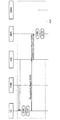
以上のインタフェースにおいては、原則として、3GPPに規定されるEPS(Evolved Packet System)のプロトコル構成が採用される。第1基地局eNBと第2基地局PhNBとに設定されるインタフェースとしては、例えば、図2のような、交換局MMEと第1基地局eNBとに設定されるインタフェースであるS1−APインタフェースを拡張した、拡張S1−AP(S1-AP extended)インタフェースが採用されると好適である。以上のインタフェースの双方は、複数のプロトコルレイヤを有する。交換局MMEから第2基地局PhNBへ送信される制御信号は、S1−APレイヤのレベルで第1基地局eNBから第2基地局PhNBに転送されてもよいし(図2)、IPレイヤのレベルで第1基地局eNBから第2基地局PhNBへ転送されてもよい(図3)。さらに、その他のレイヤのレベルで転送されてもよい。第2基地局PhNBから交換局MMEへ送信される制御信号についても同様である。 In principle, the above interface employs an Evolved Packet System (EPS) protocol configuration defined in 3GPP. As an interface set in the first base station eNB and the second base station PhNB, for example, an S1-AP interface which is an interface set in the exchange MME and the first base station eNB as shown in FIG. It is preferable that an extended S1-AP (S1-AP extended) interface is adopted. Both of the above interfaces have a plurality of protocol layers. The control signal transmitted from the switching center MME to the second base station PhNB may be transferred from the first base station eNB to the second base station PhNB at the level of the S1-AP layer (FIG. 2), or It may be transferred from the first base station eNB to the second base station PhNB at a level (FIG. 3). Furthermore, it may be transferred at the level of other layers. The same applies to the control signal transmitted from the second base station PhNB to the exchange MME.
無線通信システムCS内において、論理的な経路であるベアラ(Bearer)を介して信号が送受信される。ベアラは、必要に応じて確立され解放される動的な論理経路である。Uプレーンに関して、ユーザ装置UEと第1基地局eNB、またはユーザ装置UEと第2基地局PhNBとにデータ無線ベアラが確立される。第1基地局eNBと第1サービングゲートウェイSGW1、または第2基地局PhNBと第2サービングゲートウェイSGW2とにS1−UベアラS1Bが確立される。第1サービングゲートウェイSGW1とパケットゲートウェイPGW、または第2サービングゲートウェイSGW2とパケットゲートウェイPGWとにS5/S8ベアラが確立される。 In the radio communication system CS, signals are transmitted and received via a bearer that is a logical path. A bearer is a dynamic logical path that is established and released as needed. Regarding the U plane, a data radio bearer is established between the user apparatus UE and the first base station eNB or between the user apparatus UE and the second base station PhNB. An S1-U bearer S1B is established between the first base station eNB and the first serving gateway SGW1, or between the second base station PhNB and the second serving gateway SGW2. An S5 / S8 bearer is established in the first serving gateway SGW1 and the packet gateway PGW, or in the second serving gateway SGW2 and the packet gateway PGW.
無線通信システムCS内のノードは、それぞれ固有の識別情報を有する。識別情報には、そのノードのIPアドレス、TEID(トンネルエンドポイント識別子)、ネットワークアドレス等が含まれ得る。また、第1基地局eNBおよび第2基地局PhNBの識別情報には、その基地局が形成するセルCを識別するための物理セルID(Physical Cell ID)が含まれ得る。IPアドレスは、無線通信システムCS内でそのノードを一意に識別するアドレス値である。TEIDは、ノード間を論理的に接続するベアラ(GTPトンネル)の端点を識別する識別子である。ネットワークアドレスは、無線通信システムCSが複数のサブネットに分割されている場合に、そのノードが属するサブネットを識別するアドレス値である。無線通信システムCS内のノードは、他のノードの識別情報に基づいて他のノードを識別し、識別したノードと信号を送受信することが可能である。 Each node in the radio communication system CS has unique identification information. The identification information may include an IP address of the node, a TEID (tunnel endpoint identifier), a network address, and the like. Further, the identification information of the first base station eNB and the second base station PhNB may include a physical cell ID (Physical Cell ID) for identifying the cell C formed by the base station. The IP address is an address value that uniquely identifies the node in the radio communication system CS. The TEID is an identifier that identifies an end point of a bearer (GTP tunnel) that logically connects nodes. The network address is an address value for identifying a subnet to which the node belongs when the radio communication system CS is divided into a plurality of subnets. A node in the wireless communication system CS can identify another node based on the identification information of the other node, and can transmit / receive a signal to / from the identified node.
1(3). 各要素の構成
1(3)−1. ユーザ装置の構成
図4は、第1実施形態に係るユーザ装置UEの構成を示すブロック図である。ユーザ装置UEは、無線通信部110と記憶部120と制御部130とを備える。音声・映像等を出力する出力装置およびユーザからの指示を受け付ける入力装置等の図示は便宜的に省略されている。無線通信部110は、第1基地局eNBおよび第2基地局PhNBと無線通信を実行するための要素であり、送受信アンテナと、無線信号(電波)を受信して電気信号に変換する受信回路と、制御信号、ユーザ信号等の電気信号を無線信号(電波)に変換して送信する送信回路とを含む。制御部130は、測定情報取得部132と識別情報取得部134と報告部138とデータ送受信部150とを備える。測定情報取得部132、識別情報取得部134、及び報告部138の動作の詳細は後述される。データ送受信部150は、データ無線ベアラを介して各基地局(eNB,PhNB)とユーザ信号を送受信する。制御部130及び制御部130に含まれる以上の各要素は、ユーザ装置UE内の不図示のCPU(Central Processing Unit)が、記憶部120に記憶されたコンピュータプログラムを実行し、そのコンピュータプログラムに従って機能することにより実現される機能ブロックである。
1 (3). Configuration of each element 1 (3) -1. Configuration of User Device FIG. 4 is a block diagram illustrating a configuration of the user device UE according to the first embodiment. The user apparatus UE includes a
1(3)−2. 第1基地局の構成
図5は、第1実施形態に係る第1基地局eNBの構成を示すブロック図である。第1基地局eNBは、無線通信部210とネットワーク通信部220と記憶部230と制御部240とを備える。無線通信部210は、ユーザ装置UEと無線通信を実行するための要素であり、ユーザ装置UEの無線通信部110と同様の構成を有する。ネットワーク通信部220は、ネットワークNW内の他のノード(第2基地局PhNB、交換局MME、サービングゲートウェイSGW等)と通信を実行するための要素であり、他のノードと電気信号を送受信する。記憶部230は、通信制御に関する情報、特に、図6に示すような第2基地局PhNBの識別情報がリストされた基地局リストBL1を記憶する(詳細は後述される)。制御部240は、報告情報受信部242と経路設定判定部244と基地局判定部246と経路設定要求部250と転送部252と経路解放部254とデータ送受信部270とを備える。データ送受信部270は、データ無線ベアラを介してユーザ装置UEとユーザ信号を送受信(中継)すると共に、S1−UベアラS1Bを介して第1サービングゲートウェイSGW1とユーザ信号を送受信(中継)する。制御部240が含むその他の要素の動作については後述される。制御部240及び制御部240に含まれる以上の各要素は、第1基地局eNB内の不図示のCPUが、記憶部230に記憶されたコンピュータプログラムを実行し、そのコンピュータプログラムに従って機能することにより実現される機能ブロックである。
1 (3) -2. Configuration of First Base Station FIG. 5 is a block diagram showing a configuration of the first base station eNB according to the first embodiment. The first base station eNB includes a
1(3)−3. 第2基地局の構成
図7は、第1実施形態に係る第2基地局PhNBの構成を示すブロック図である。第2基地局PhNBは、無線通信部310とネットワーク通信部320と記憶部330と制御部340とを備える。無線通信部310は、ユーザ装置UEと無線通信を実行するための要素であり、第1基地局eNBの無線通信部210と同様の構成を有する。ネットワーク通信部320は、第1基地局eNBおよび第2サービングゲートウェイSGW2と通信を実行するための要素であり、他のノードと電気信号を送受信する。記憶部330は通信制御に関する情報を有する。制御部340は、経路設定部342と応答部344とデータ送受信部350とを備える。データ送受信部350は、データ無線ベアラを介してユーザ装置UEとユーザ信号を送受信(中継)すると共に、S1−UベアラS1Bを介して第2サービングゲートウェイSGW2とユーザ信号を送受信(中継)する。制御部340が含むその他の要素の動作については後述される。制御部340及び制御部340に含まれる以上の各要素は、第2基地局PhNB内の不図示のCPUが、記憶部330に記憶されたコンピュータプログラムを実行し、そのコンピュータプログラムに従って機能することにより実現される機能ブロックである。
1 (3) -3. Configuration of Second Base Station FIG. 7 is a block diagram showing a configuration of the second base station PhNB according to the first embodiment. The second base station PhNB includes a
1(3)−4. 交換局の構成
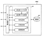
図8は、第1実施形態に係る交換局MMEの構成を示すブロック図である。交換局MMEは、ネットワーク通信部410と記憶部420と制御部430とを備える。ネットワーク通信部410は、ネットワークNW内の他のノード(サービングゲートウェイSGW(SGW1,SGW2)、第1基地局eNB等)と通信を実行するための要素であり、第1基地局eNBのネットワーク通信部220と同様の構成を有する。記憶部420は、通信制御に関する情報を記憶する。制御部430は、基地局リスト生成部432と基地局リスト送信部434とゲートウェイ選択部440と経路制御部442とを備える。制御部430が含む以上の要素の動作については後述される。制御部430及び制御部430に含まれる以上の各要素は、交換局MME内の不図示のCPUが、記憶部420に記憶されたコンピュータプログラムを実行し、そのコンピュータプログラムに従って機能することにより実現される機能ブロックである。
1 (3) -4. Configuration of Switching Center FIG. 8 is a block diagram showing a configuration of the switching center MME according to the first embodiment. The switching center MME includes a
1(3)−5. サービングゲートウェイの構成
図9は、第1実施形態に係るサービングゲートウェイSGW(SGW1,SGW2)の構成を示すブロック図である。サービングゲートウェイSGWは、ネットワーク通信部510と記憶部520と制御部530とを備える。ネットワーク通信部510は、ネットワークNW内の他のノード(第1基地局eNB又は第2基地局PhNB、交換局MME、パケットゲートウェイPGW等)と通信を実行するための要素であり、第1基地局eNBのネットワーク通信部220と同様の構成を有する。記憶部520は、通信制御に関する情報を記憶する。制御部530は、通信制御部532と応答部534と経路設定部536とデータ送受信部540とを備える。データ送受信部540は、S1−UベアラS1Bを介して第1基地局eNBまたは第2基地局PhNBとユーザ信号を送受信(中継)すると共に、S5/S8ベアラを介してパケットゲートウェイPGWとユーザ信号を送受信(中継)する。制御部530が含むその他の要素の動作については後述される。制御部530及び制御部530に含まれる以上の各要素は、サービングゲートウェイSGW内の不図示のCPUが、記憶部520に記憶されたコンピュータプログラムを実行し、そのコンピュータプログラムに従って機能することにより実現される機能ブロックである。
1 (3) -5. Configuration of Serving Gateway FIG. 9 is a block diagram illustrating a configuration of the serving gateway SGW (SGW1, SGW2) according to the first embodiment. The serving gateway SGW includes a
1(3)−6. パケットゲートウェイの構成
図10は、第1実施形態に係るパケットゲートウェイPGWの構成を示すブロック図である。パケットゲートウェイPGWはネットワーク通信部610と外部ネットワーク通信部620と記憶部630と制御部640とを備える。ネットワーク通信部610は、ネットワークNW内の他のノード(サービングゲートウェイSGW等)と通信を実行するための要素であり他のノードと電気信号を送受信する。外部ネットワーク通信部620は、インターネットINと通信を実行するための要素であり、必要に応じて電気信号(データ信号)のプロトコル変換を実行する。記憶部630は、通信制御に関する情報を記憶する。制御部640は、通信制御部642とデータ送受信部644とを備える。通信制御部642は無線通信システムCSの通信制御を実行する要素であり、サービングゲートウェイSGW(SGW1,SGW2)等とネットワーク通信部610を介して制御信号を送受信する。データ送受信部634は、ネットワーク通信部610を介して受信したユーザ装置UE発のデータ信号を、外部ネットワーク通信部620を介してインターネットIN(インターネットIN内の外部サーバ)に送信(中継)するとともに、外部ネットワーク通信部620を介してインターネットIN(インターネットIN内の外部サーバ)から受信したデータ信号を、ネットワーク通信部610を介してユーザ装置UEに送信(中継)する。制御部640及び制御部640に含まれる以上の各要素は、パケットゲートウェイPGW内の不図示のCPUが、記憶部630に記憶されたコンピュータプログラムを実行し、そのコンピュータプログラムに従って機能することにより実現される機能ブロックである。
1 (3) -6. Configuration of Packet Gateway FIG. 10 is a block diagram showing a configuration of the packet gateway PGW according to the first embodiment. The packet gateway PGW includes a
1(4). サービングゲートウェイの選択及びS1−Uベアラの設定
図11を参照して、第1実施形態のサービングゲートウェイの選択(S10)及びS1−Uベアラの設定(S50)の動作の一例を説明する。図11の例では、第1基地局eNBと第1サービングゲートウェイSGW1とにS1−UベアラS1Bが確立されていると想定する。そして、以上のS1−UベアラS1Bに対応するデータ無線ベアラが第1基地局eNBとユーザ装置UEとに確立され、以上のS1−UベアラS1Bに対応するS5/S8ベアラが第1サービングゲートウェイSGW1とパケットゲートウェイPGWとに確立されていると想定する。したがって、以上の想定において、当初、ユーザ装置UEは、第1基地局eNB、第1サービングゲートウェイSGW1、及びパケットゲートウェイPGWを経由してインターネットINと通信を実行する。また、Cプレーンに関しては、第1基地局eNBとユーザ装置UEとにシグナリング無線ベアラが確立されていると想定する。以上から理解される通り、ユーザ装置UEは、図11の当初、第1基地局eNBに無線接続している。
1 (4). Selection of Serving Gateway and Setting of S1-U Bearer With reference to FIG. 11, an example of operation of selection of a serving gateway (S10) and setting of an S1-U bearer (S50) according to the first embodiment will be described. In the example of FIG. 11, it is assumed that the S1-U bearer S1B is established between the first base station eNB and the first serving gateway SGW1. Then, the data radio bearer corresponding to the above S1-U bearer S1B is established in the first base station eNB and the user apparatus UE, and the S5 / S8 bearer corresponding to the above S1-U bearer S1B is the first serving gateway SGW1. And the packet gateway PGW. Therefore, in the above assumption, initially, the user apparatus UE executes communication with the Internet IN via the first base station eNB, the first serving gateway SGW1, and the packet gateway PGW. Moreover, regarding the C plane, it is assumed that a signaling radio bearer is established between the first base station eNB and the user apparatus UE. As understood from the above, the user apparatus UE is wirelessly connected to the first base station eNB at the beginning of FIG.
ユーザ装置UEの無線通信部110は、近傍の各基地局(第1基地局eNB、第2基地局PhNB)から無線信号を受信する。ユーザ装置UEの測定情報取得部132は各基地局から受信した無線信号の受信品質に関する測定情報を取得する(S100)。より具体的には、ユーザ装置UEの測定情報取得部132は、各基地局(第1基地局eNB、第2基地局PhNB)が送信する無線信号に含まれる参照信号の受信電力(又は受信品質)を測定情報として取得する。また、ユーザ装置UEの識別情報取得部134は、各基地局が送信する無線信号に含まれるその基地局の識別情報(物理セルID)を取得する。すなわち、ユーザ装置UEの識別情報取得部134は受信した各測定情報に対応する基地局の識別情報を取得する(S100)。その後、ユーザ装置UEの報告部138は、基地局毎に取得した測定情報および識別情報を含むMeasurement Reportメッセージ(報告情報)を、無線接続中の第1基地局に送信(報告)する(S120)。
The
第1基地局eNBの報告情報受信部242が、ユーザ装置UEから送信されたMeasurement Reportメッセージを受信する。報告情報受信部242は、Measurement Reportメッセージに含まれる測定情報を経路設定判定部244に供給すると共に、Measurement Reportメッセージに含まれる識別情報を基地局判定部246に供給する。経路設定判定部244は、測定情報に基づいて、その測定情報に対応する基地局を1つの端点とするS1−UベアラS1Bを設定すべきか否かを判定し、その判定結果を経路設定要求部250に供給する(S140)。本例では、第1基地局eNBからの無線信号の受信電力よりも第2基地局PhNBからの無線信号の受信電力が大きいことに基づき、第2基地局PhNBを1つの端点とするS1−UベアラS1Bを設定すべきと、経路設定判定部244が判定すると想定する。また、基地局判定部246は、基地局の識別情報に基づいて、その識別情報に対応する基地局が第2基地局PhNBであるか否かを、記憶部230に記憶された基地局リストBL1を用いて判定し、その判定結果を経路設定要求部250に供給する(S140)。基地局リストBL1は、第2基地局PhNBの識別情報を記憶するリストである。したがって、基地局判定部246は、ある基地局の識別情報が基地局リストBL1に記憶されていることに基づいて、その基地局が第2基地局PhNBであると判定できる。
The report
第1基地局eNBの経路設定要求部250は、経路設定判定部244がS1−UベアラS1Bを設定すべきと判定した場合であって、そのS1−UベアラS1Bの1つの端点となるべき基地局が第2基地局PhNBであると基地局判定部246が判定したときに、交換局MMEに対し、そのS1−UベアラS1Bを設定することを要求するBearer Setup Requestメッセージ(経路設定要求)を、Cプレーン経路を介して送信する(S160)。交換局MMEのゲートウェイ選択部440は、第1基地局eNBから受信したBearer Setup Requestメッセージが設定を要求するS1−UベアラS1Bの別の端点となるサービングゲートウェイSGWを選択する(S180)。サービングゲートウェイSGWの選択基準は任意であるが、例えば、第2基地局PhNBとの論理的距離の近さや、サービングゲートウェイSGWの輻輳度合い等(またはこれらの組合せ)が、選択基準として採用され得る。本例では、ゲートウェイ選択部440が、S1−UベアラS1Bの別の端点として、第2基地局PhNBと接続される第2サービングゲートウェイSGW2を選択すると想定する。
以降、以上のステップS100からS180までの第1実施形態のサービングゲートウェイ選択動作を、纏めてステップS10と称する。
The route
Henceforth, the serving gateway selection operation | movement of 1st Embodiment from the above step S100 to S180 is collectively called step S10.
交換局MMEの経路制御部442は、ゲートウェイ選択部440が選択した、以上のS1−UベアラS1Bの別の端点となる第2サービングゲートウェイSGW2に対し、その第2サービングゲートウェイSGW2と第2基地局PhNBとにS1−UベアラS1Bを設定することを指示するBearer Setup Requirementメッセージ(第1経路設定指示)を送信する(S500)。第2サービングゲートウェイSGW2の通信制御部532は、交換局MMEからBearer Setup Requirementメッセージを受信すると、応答部534を制御して(S520)、その第2サービングゲートウェイSGW2の識別情報(TEID等)を含むBearer Setup Ackメッセージ(第1経路設定指示応答)を交換局MMEに送信させる(S540)。
The
交換局MMEの経路制御部442は、第2サービングゲートウェイSGW2からのBearer Setup Ackメッセージを受信すると、第2サービングゲートウェイSGW2の識別情報を含むBearer Setup Requirementメッセージ(第2経路設定指示)を生成し(S560)、Cプレーン経路を介して第1基地局eNBに送信する(S580)。第1基地局eNBの転送部252は、交換局MMEから送信されたBearer Setup Requirementメッセージを第2基地局PhNBに転送する(S600)。より具体的には、転送部252は、Bearer Setup Requirementメッセージに含まれる宛先ノードの識別情報を、第1基地局eNBの識別情報から第2基地局PhNBの識別情報に書き換える。以上の宛先ノードの識別情報は、いずれのプロトコルレイヤの識別情報でもよい。例えば、S1−APレイヤの識別情報であるトンネルエンドポイント識別子でもよいし、IPレイヤの識別情報であるIPアドレスでもよい(図2、図3)。
When receiving the Bearer Setup Ack message from the second serving gateway SGW2, the
第2基地局PhNBの経路設定部342は、第1基地局eNBから転送されたBearer Setup Requirementメッセージに含まれる第2サービングゲートウェイSGW2の識別情報を用いて、上りリンクのS1−UベアラS1B−Uを設定する(S620)。上りリンクのS1−UベアラS1B−Uが設定されると、応答部344は、以上のベアラ設定が完了したことを示す、第2基地局PhNBの識別情報を含むSetup Completeメッセージ(第2経路設定指示応答)を第1基地局eNBに送信する(S640)。第1基地局eNBの転送部252は、第2基地局PhNBから送信されたSetup Completeメッセージを、Cプレーン経路を介して交換局MMEに転送する(S660)。
The
交換局MMEの経路制御部442は、第1基地局eNBから転送されたSetup Completeメッセージを受信すると、そのSetup Completeメッセージが含む第2基地局PhNBの識別情報を含めたBearer Setup Requirementメッセージ(第3経路設定指示)を生成し(S680)、第2サービングゲートウェイSGW2に送信する(S700)。第2サービングゲートウェイSGW2の経路設定部536は、交換局MMEから送信されたBearer Setup Requirementメッセージに含まれる第2基地局PhNBの識別情報を用いて、下りリンクのS1−UベアラS1B−Dを設定する(S720)。第2サービングゲートウェイSGW2の経路設定部536は、下りリンクのS1−UベアラS1B−Dが設定されると、Setup Completeメッセージ(第3経路設定指示応答)を交換局MMEに送信する(S740)。以上の動作により、双方向的に通信可能なS1−UベアラS1Bが設定される。なお、S1−UベアラS1Bの設定後も、ユーザ装置UEと第1基地局eNBとに確立されたCプレーン経路(シグナリング無線ベアラ)は維持される。
以降、以上のステップS500からS740までの第1実施形態のS1−Uベアラ設定動作を、纏めてステップS50と称する。
When receiving the Setup Complete message transferred from the first base station eNB, the
Hereinafter, the S1-U bearer setting operation of the first embodiment from the above steps S500 to S740 will be collectively referred to as step S50.
1(5). 本実施形態の効果
以上に説明した第1実施形態によれば、第1基地局eNBとは異なる新たな種別の第2基地局PhNBを備える無線通信システムが実現される。以上の構成によれば、ユーザ装置UEから送信された報告情報に含まれる識別情報に基づいて、その識別情報に対応する基地局が第2基地局PhNBであるか否かが判定される。したがって、S1−UベアラS1Bを確立すべき基地局が、交換局MMEに対するCプレーン経路を有する第1基地局eNBであるか、交換局MMEに対するCプレーン経路を有さない第2基地局PhNBであるかが明らかとなり、以降の判定に役立てられる。
1 (5). Effects of the present embodiment According to the first embodiment described above, a radio communication system including a new type of second base station PhNB different from the first base station eNB is realized. According to the above configuration, based on the identification information included in the report information transmitted from the user apparatus UE, it is determined whether or not the base station corresponding to the identification information is the second base station PhNB. Therefore, the base station to establish the S1-U bearer S1B is the first base station eNB having a C plane path to the switching center MME or the second base station PhNB not having a C plane path to the switching center MME. It becomes clear whether it is present or not, and this is useful for subsequent determinations.
また、S1−UベアラS1Bが確立されるべきと判定され、S1−UベアラS1Bの1つの端点が第2基地局PhNBである場合に、第2基地局PhNBの接続先(S1−UベアラS1Bの設定先)となるサービングゲートウェイSGWを交換局MMEが選択する。したがって、S1−UベアラS1Bの端点である第2基地局PhNBに適した接続先(S1−UベアラS1Bの設定先)が選択され得る。 When it is determined that the S1-U bearer S1B should be established and one end point of the S1-U bearer S1B is the second base station PhNB, the connection destination of the second base station PhNB (S1-U bearer S1B The switching station MME selects the serving gateway SGW that becomes the setting destination). Therefore, the connection destination (setting destination of the S1-U bearer S1B) suitable for the second base station PhNB that is the end point of the S1-U bearer S1B can be selected.
さらに、交換局MMEが、第2サービングゲートウェイSGW2及び第2基地局PhNBを主導的に制御してS1−UベアラS1Bを確立する。交換局MMEは、第1基地局eNBを経由して第2基地局PhNBと制御信号を送受信する。したがって、以上の構成においては、第2基地局PhNBと交換局MMEとの間にCプレーン経路が存在しないにも関わらず、第2基地局PhNBに対するUプレーン経路が設定され得る。 Further, the switching center MME establishes the S1-U bearer S1B by controlling the second serving gateway SGW2 and the second base station PhNB. The exchange MME transmits and receives control signals to and from the second base station PhNB via the first base station eNB. Therefore, in the above configuration, the U plane path for the second base station PhNB can be set even though the C plane path does not exist between the second base station PhNB and the switching center MME.
第2実施形態
本発明の第2実施形態を以下に説明する。以下に例示する各実施形態において、作用、機能が第1実施形態と同等である要素については、以上の説明で参照した符号を流用して各々の説明を適宜に省略する。
Second Embodiment A second embodiment of the present invention will be described below. In each embodiment illustrated below, about the element which an effect | action and a function are equivalent to 1st Embodiment, the code | symbol referred by the above description is diverted and each description is abbreviate | omitted suitably.
第1実施形態では、S1−UベアラS1Bを設定すべきサービングゲートウェイSGWを交換局MMEが選択する(S10)。また、交換局MMEの主導の下にS1−UベアラS1Bが設定される(S50)。第2実施形態では、S1−UベアラS1Bを設定すべきサービングゲートウェイSGWを第1基地局eNBが選択する(S12)。また、第1基地局eNBの主導の下にS1−UベアラS1Bが設定される(S52)。 In the first embodiment, the switching center MME selects the serving gateway SGW in which the S1-U bearer S1B is to be set (S10). Further, the S1-U bearer S1B is set under the initiative of the switching center MME (S50). In 2nd Embodiment, the 1st base station eNB selects the serving gateway SGW which should set S1-U bearer S1B (S12). Further, the S1-U bearer S1B is set under the initiative of the first base station eNB (S52).
2(1). 各要素の構成
2(1)−1. 第1基地局の構成
図12は、第2実施形態の第1基地局eNBに関するインタフェースの一例を示す図である。第1基地局eNBと第2基地局PhNBとに設定されるインタフェースとしては、例えば、第1基地局eNB同士に設定される従来のX2−APインタフェースを改変したX3−APインタフェースが採用されると好適である。X3−APインタフェースは、複数のプロトコルレイヤを有するインタフェースであり、第1基地局eNBを上位、第2基地局PhNBを下位として非対称的に設定される。また、第1基地局eNBと交換局MMEとに設定されるインタフェースとしては、例えば、交換局MMEを上位、第1基地局eNBを下位として非対称的に設定される従来のS1−APインタフェースを改変したS1e−APインタフェースが採用されると好適である。S1e−APインタフェースは、第1基地局eNBを上位、交換局MMEを下位として(すなわち、S1−APインタフェースとは逆に)非対称的に設定される。換言すると、以上の第2実施形態のインタフェースは、第1基地局eNBの制御部240によって主導的に制御される。
2 (1). Configuration of each element 2 (1) -1. Configuration of First Base Station FIG. 12 is a diagram illustrating an example of an interface related to the first base station eNB of the second embodiment. As an interface set in the first base station eNB and the second base station PhNB, for example, an X3-AP interface obtained by modifying a conventional X2-AP interface set between the first base stations eNB is adopted. Is preferred. The X3-AP interface is an interface having a plurality of protocol layers, and is set asymmetrically with the first base station eNB as the upper level and the second base station PhNB as the lower level. Further, as an interface set in the first base station eNB and the switching center MME, for example, a conventional S1-AP interface that is set asymmetrically with the switching center MME as the upper level and the first base station eNB as the lower level is modified. The S1e-AP interface is preferably used. The S1e-AP interface is set asymmetrically with the first base station eNB as the upper level and the switching center MME as the lower level (that is, contrary to the S1-AP interface). In other words, the interface of the above second embodiment is controlled predominantly by the
図13は、第2実施形態に係る第1基地局eNBの構成を示すブロック図である。第2実施形態の第1基地局eNBの制御部240は、ゲートウェイ選択部248をさらに有する。ゲートウェイ選択部248は、制御部240内の他の要素と同様に、コンピュータプログラムの実行により実現される機能ブロックである。また、第2実施形態の第1基地局eNBが備える記憶部230は、図14に示すような、第2基地局PhNBの識別情報と、各識別情報に対応する第2基地局PhNBを1つの端点とするS1−UベアラS1Bの別の端点となるべきサービングゲートウェイSGWの識別情報とを対応付けて記憶する基地局リストBL2を記憶する。
FIG. 13 is a block diagram illustrating a configuration of the first base station eNB according to the second embodiment. The
2(1)−2. 交換局の構成
図15は、第2実施形態に係る交換局MMEの構成を示すブロック図である。第2実施形態の交換局MMEの制御部430は、第1実施形態の制御部430が備えるゲートウェイ選択部440および経路制御部442に代えて、要求送信部444と応答送信部446と経路解放部448とを備える。要求送信部444、応答送信部446、および経路解放部448は、制御部430内の他の要素と同様に、コンピュータプログラムの実行により実現される機能ブロックである。
2 (1) -2. Configuration of Switching Center FIG. 15 is a block diagram showing the configuration of the switching center MME according to the second embodiment. The
2(2). サービングゲートウェイの選択及びS1−Uベアラの設定
図16を参照して、第2実施形態のサービングゲートウェイの選択及びS1−Uベアラの設定の動作の一例を説明する。Uプレーンのベアラ及びCプレーンのベアラに関する当初の想定は、図11と同様である。ユーザ装置UEは、第1実施形態と同様にして、測定情報および識別情報を取得する(S100)。ユーザ装置UE(報告部138)は、取得された測定情報と識別情報とを含むMeasurement Reportメッセージ(報告情報)を、無線接続中の第1基地局eNBに送信する(S120)。第1基地局eNB(報告情報受信部242)がMeasurement Reportメッセージを受信した後、測定情報が経路設定判定部244に供給され、識別情報が基地局判定部246に供給される。
2 (2). Selection of Serving Gateway and Setting of S1-U Bearer With reference to FIG. 16, an example of the operation of selecting the serving gateway and setting the S1-U bearer according to the second embodiment will be described. The initial assumptions regarding the U-plane bearer and the C-plane bearer are the same as in FIG. The user apparatus UE acquires measurement information and identification information as in the first embodiment (S100). The user apparatus UE (report unit 138) transmits a Measurement Report message (report information) including the acquired measurement information and identification information to the first base station eNB that is wirelessly connected (S120). After the first base station eNB (report information reception unit 242) receives the Measurement Report message, the measurement information is supplied to the route setting
経路設定判定部244は、測定情報に基づいて、その測定情報に対応する基地局を1つの端点とするS1−UベアラS1Bを設定すべきか否かを判定し、その判定結果をゲートウェイ選択部248に供給する(S140)。本例では、前述と同様に、第2基地局PhNBを1つの端点とするS1−UベアラS1Bを設定すべきと、経路設定判定部244が判定すると想定する。また、基地局判定部246は、基地局の識別情報に基づいて、その識別情報に対応する基地局が第2基地局PhNBであるか否かを、記憶部230に記憶された基地局リストBL2を用いて判定し、その判定結果をゲートウェイ選択部248に供給する(S140)。前述のように、基地局リストBL2は第2基地局PhNBの識別情報を記憶するから、基地局判定部246は、ある基地局の識別情報が基地局リストBL2に記憶されていることに基づいて、その基地局が第2基地局PhNBであると判定できる。
Based on the measurement information, the route setting
第1基地局eNBのゲートウェイ選択部248は、経路設定判定部244がS1−UベアラS1Bを設定すべきと判定した場合であって、そのS1−UベアラS1Bの1つの端点となるべき基地局が第2基地局PhNBであると基地局判定部246が判定したときに、そのS1−UベアラS1Bの別の端点となるサービングゲートウェイSGWを、基地局リストBL2を用いて選択し、選択されたサービングゲートウェイSGWを示す情報を経路設定要求部250に供給する(S150)。前述のように、基地局リストBL2は第2基地局PhNBの識別情報とサービングゲートウェイSGWの識別情報とを対応付けて記憶するから、ゲートウェイ選択部248は、基地局判定部246に判定された第2基地局PhNBに対応するサービングゲートウェイSGWを1つ選択することが可能である。本例では、ゲートウェイ選択部248が、S1−UベアラS1Bの別の端点として、第2基地局PhNBと接続される第2サービングゲートウェイSGW2を選択すると想定する。第1基地局eNBの経路設定要求部250は、第2基地局PhNBと、ゲートウェイ選択部248が選択した第2サービングゲートウェイSGW2とにS1−UベアラS1Bを設定することを要求するBearer Setup Requirementメッセージ(経路設定要求)を、Cプレーン経路を介して交換局MMEに送信する(S170)。
以降、以上のステップS100からS170までの第2実施形態のサービングゲートウェイ選択動作を、纏めてステップS12と称する。
The
Henceforth, the serving gateway selection operation | movement of 2nd Embodiment from the above step S100 to S170 is collectively called step S12.
交換局MMEの要求送信部444は、第1基地局eNBの経路設定要求部250から送信されたBearer Setup Requirementメッセージを受信すると、ゲートウェイ選択部248が選択したS1−UベアラS1Bの別の端点となる第2サービングゲートウェイSGW2に対するBearer Setup Requirementメッセージを送信する(S510)。第2サービングゲートウェイSGW2の通信制御部532は、交換局MMEからBearer Setup Requirementメッセージを受信すると、応答部534を制御して(S530)、その第2サービングゲートウェイSGW2の識別情報を含むBearer Setup Ackメッセージ(経路設定要求完了応答)を交換局MMEに送信させる(S550)。交換局MMEの応答送信部446は、第2サービングゲートウェイSGW2からBearer Setup Ackメッセージを受信すると、第2サービングゲートウェイSGW2の識別情報を含む、第1基地局eNBに対するBearer Setup Ackメッセージを、Cプレーン経路を介して送信する(S570)。
Upon receiving the Bearer Setup Requirement message transmitted from the route
第1基地局eNBの経路設定要求部250は、交換局MMEからBearer Setup Ackメッセージを受信すると、第2サービングゲートウェイSGW2の識別情報を含むBearer Setup Requirementメッセージ(経路設定要求)を生成し(S590)、第2基地局PhNBに送信する(S610)。第2基地局PhNBの経路設定部342は、第1基地局eNBの経路設定要求部250から送信されたBearer Setup Requirementメッセージに含まれる第2サービングゲートウェイSGW2の識別情報を用いて、上りリンクのS1−UベアラS1B−Uを設定する(S630)。上りリンクのS1−UベアラS1B−Uが設定されると、応答部344は、以上のベアラ設定が完了したことを示す、第2基地局PhNBの識別情報を含むSetup Completeメッセージ(経路設定要求完了応答)を第1基地局eNBに送信する(S650)。
When receiving the Bearer Setup Ack message from the switching center MME, the route
第1基地局eNBの経路設定要求部250は、Setup Completeメッセージを受信すると、第2基地局PhNBの識別情報を含むBearer Modify Requestメッセージ(経路変更要求)を生成し(S670)、Cプレーン経路を介して交換局MMEに送信する(S690)。交換局MMEの要求送信部444は、第1基地局eNBの経路設定要求部250からのBearer Modify Requestメッセージを受信すると、第2サービングゲートウェイSGW2に対するBearer Modify Requestメッセージを送信する(S710)。第2サービングゲートウェイSGW2の経路設定部536は、交換局MMEから送信されたBearer Modify Requestメッセージに含まれる第2基地局PhNBの識別情報を用いて、下りリンクのS1−UベアラS1B−Dを設定する(S730)。第2サービングゲートウェイSGW2の経路設定部536は、下りリンクのS1−UベアラS1B−Dが設定されると、Modify Completeメッセージ(経路変更要求完了応答)を交換局MMEに送信する(S750)。交換局MMEの応答送信部446は、第2サービングゲートウェイSGW2からのModify Completeメッセージを第1基地局eNBに送信する(S770)。以上の動作により、双方向的に通信可能なS1−UベアラS1Bが設定される。なお、S1−UベアラS1Bの設定後も、ユーザ装置UEと第1基地局eNBとに確立されたCプレーン経路(シグナリング無線ベアラ)は維持される。
以降、以上のステップS510からS770までの第2実施形態のS1−Uベアラ設定動作を、纏めてステップS52と称する。
When receiving the Setup Complete message, the route
Hereinafter, the S1-U bearer setting operation of the second embodiment from the above steps S510 to S770 is collectively referred to as step S52.
2(3). 本実施形態の効果
以上に説明した第2実施形態によれば、第1実施形態と同様に、第1基地局eNBとは異なる新たな種別の第2基地局PhNBを備える無線通信システムが実現される。以上の構成によれば、ユーザ装置UEから送信された報告情報に含まれる識別情報に基づいて、その識別情報に対応する基地局が第2基地局PhNBであるか否かが判定される。したがって、S1−UベアラS1Bを確立すべき基地局が、交換局MMEに対するCプレーン経路を有する第1基地局eNBであるか、交換局MMEに対するCプレーン経路を有さない第2基地局PhNBであるかが明らかとなり、以降の判定に役立てられる。
2 (3). Effects of this Embodiment According to the second embodiment described above, a radio communication system including a new type of second base station PhNB different from the first base station eNB is realized, as in the first embodiment. The According to the above configuration, based on the identification information included in the report information transmitted from the user apparatus UE, it is determined whether or not the base station corresponding to the identification information is the second base station PhNB. Therefore, the base station to establish the S1-U bearer S1B is the first base station eNB having a C plane path to the switching center MME or the second base station PhNB not having a C plane path to the switching center MME. It becomes clear whether it is present or not, and this is useful for subsequent determinations.
また、S1−UベアラS1Bが確立されるべきと判定され、S1−UベアラS1Bの1つの端点が第2基地局PhNBである場合に、第2基地局PhNBの接続先(S1−UベアラS1Bの設定先)となるサービングゲートウェイSGWを第1基地局eNBが選択する。したがって、S1−UベアラS1Bの端点である第2基地局PhNBに適した接続先(S1−UベアラS1Bの設定先)が選択され得る。 When it is determined that the S1-U bearer S1B should be established and one end point of the S1-U bearer S1B is the second base station PhNB, the connection destination of the second base station PhNB (S1-U bearer S1B The first base station eNB selects a serving gateway SGW to be a setting destination). Therefore, the connection destination (setting destination of the S1-U bearer S1B) suitable for the second base station PhNB that is the end point of the S1-U bearer S1B can be selected.
さらに、交換局MMEではなく、第1基地局eNBが第2サービングゲートウェイSGW2及び第2基地局PhNBを主導的に制御してS1−UベアラS1Bを確立する。したがって、以上の構成においては、第2基地局PhNBと交換局MMEとの間にCプレーン経路が存在しないにも関わらず、第2基地局PhNBに対するUプレーン経路が設定され得る。 Further, the first base station eNB, not the switching center MME, controls the second serving gateway SGW2 and the second base station PhNB to establish the S1-U bearer S1B. Therefore, in the above configuration, the U plane path for the second base station PhNB can be set even though the C plane path does not exist between the second base station PhNB and the switching center MME.
第3実施形態
第1実施形態および第2実施形態においては、第1基地局eNB(経路設定判定部244)が、ユーザ装置UEから報告された測定情報に基づいて、その測定情報に対応する基地局にS1−UベアラS1Bを設定すべきか否かを判定する。第3実施形態では、交換局MMEがそのような経路設定判定部を備える。
3rd Embodiment In 1st Embodiment and 2nd Embodiment, the 1st base station eNB (path | route setting determination part 244) is a base corresponding to the measurement information based on the measurement information reported from the user apparatus UE. It is determined whether or not the S1-U bearer S1B should be set in the station. In the third embodiment, the exchange MME includes such a route setting determination unit.
3(1). 交換局の構成
図17は、第3実施形態に係る交換局MMEの構成を示すブロック図である。第3実施形態の交換局MMEの記憶部420は、図6に示される基地局リストBL1を記憶する。また、第3実施形態の交換局MMEの制御部430は、経路設定判定部436と基地局判定部438とを更に備える。経路設定判定部436および基地局判定部438は、制御部430内の他の要素と同様に、コンピュータプログラムの実行により実現される機能ブロックである。
3 (1). Configuration of Switching Center FIG. 17 is a block diagram showing a configuration of the switching center MME according to the third embodiment. The
3(2). サービングゲートウェイの選択
図18を参照して、第3実施形態のサービングゲートウェイの選択動作の一例を説明する。Uプレーンのベアラ及びCプレーンのベアラに関する当初の想定は、図11と同様である。ユーザ装置UEは、第1実施形態と同様にして、測定情報および識別情報を取得する(S200)。ユーザ装置UE(報告部138)は、取得された測定情報と識別情報とを含むMeasurement Reportメッセージ(報告情報)を、無線接続中の第1基地局eNBに送信する(S220)。第1基地局eNBの転送部252は、受信したMeasurement Reportメッセージを、Cプレーン経路を介して交換局MMEに送信する(S240)。すなわち、転送部252は、基地局送信部として機能する。
3 (2). Serving Gateway Selection An example of the serving gateway selection operation of the third embodiment will be described with reference to FIG. The initial assumptions regarding the U-plane bearer and the C-plane bearer are the same as in FIG. The user apparatus UE acquires measurement information and identification information in the same manner as in the first embodiment (S200). The user apparatus UE (report unit 138) transmits a Measurement Report message (report information) including the acquired measurement information and identification information to the first base station eNB that is wirelessly connected (S220). The
交換局MMEの経路設定判定部436は、Measurement Reportメッセージに含まれる測定情報基づいて、その測定情報に対応する基地局を1つの端点とするS1−UベアラS1Bを設定すべきか否かを判定し、その判定結果をゲートウェイ選択部440に供給する(S260)。本例では、前述の実施形態と同様に、第2基地局PhNBを1つの端点とするS1−UベアラS1Bを設定すべきと、経路設定判定部436が判定すると想定する。また、交換局MMEの基地局判定部438は、Measurement Reportメッセージに含まれる基地局の識別情報に基づいて、その識別情報に対応する基地局が第2基地局PhNBであるか否かを、前述の実施形態と同様に、記憶部420に記憶された基地局リストBL1を用いて判定し、その判定結果をゲートウェイ選択部440に供給する(S260)。交換局MMEのゲートウェイ選択部440は、経路設定判定部436がS1−UベアラS1Bを設定すべきと判定した場合であって、そのS1−UベアラS1Bの1つの端点となるべき基地局が第2基地局PhNBであると基地局判定部438が判定したときに、そのS1−UベアラS1Bの別の端点となるサービングゲートウェイSGWを選択する(S280)。
以降、以上のステップS200からS280までの第3実施形態のサービングゲートウェイ選択動作を、纏めてステップS20と称する。
Based on the measurement information included in the Measurement Report message, the path setting
Henceforth, the serving gateway selection operation | movement of 3rd Embodiment from the above step S200 to S280 is collectively called step S20.
以上のステップS20が完了すると、交換局MMEは、S1−UベアラS1Bの別の端点として選択されたサービングゲートウェイSGWを把握している状態となる。以上の状態は、第1実施形態のステップS10が完了した状態および第2実施形態のステップS12が完了した状態と同様であると理解できる。したがって、第3実施形態のステップS20の完了後には、第1実施形態のステップS50によるS1−Uベアラ設定動作が実行されてもよいし、第2実施形態のステップS52によるS1−Uベアラ設定動作が実行されてもよい。 When the above step S20 is completed, the switching center MME is in a state of grasping the serving gateway SGW selected as another end point of the S1-U bearer S1B. It can be understood that the above state is the same as the state in which step S10 of the first embodiment is completed and the state in which step S12 of the second embodiment is completed. Therefore, after step S20 of the third embodiment is completed, the S1-U bearer setting operation according to step S50 of the first embodiment may be executed, or the S1-U bearer setting operation according to step S52 of the second embodiment. May be executed.
3(3). 本実施形態の効果
以上に説明した第3実施形態によれば、第1実施形態および第2実施形態と同様に、第1基地局eNBとは異なる新たな種別の第2基地局PhNBを備える無線通信システムが実現される。また、以上の構成によれば、前述の実施形態と同様の効果が奏される。
3 (3). Advantages of the present embodiment According to the third embodiment described above, similarly to the first embodiment and the second embodiment, a radio having a new type of second base station PhNB different from the first base station eNB. A communication system is realized. Moreover, according to the above structure, the effect similar to the above-mentioned embodiment is show | played.
第4実施形態
第1実施形態および第2実施形態では、識別情報に対応する基地局が第2基地局であるか否かを第1基地局eNB(基地局判定部246)が判定し、第3実施形態では、識別情報に対応する基地局が第2基地局であるか否かを交換局MME(基地局判定部438)が判定する。第4実施形態では、第2基地局であるか否かを判定する基地局判定部をユーザ装置UEが備える。
Fourth Embodiment In the first embodiment and the second embodiment, the first base station eNB (base station determination unit 246) determines whether or not the base station corresponding to the identification information is the second base station, and the first In the third embodiment, the switching center MME (base station determination unit 438) determines whether or not the base station corresponding to the identification information is the second base station. In 4th Embodiment, the user apparatus UE is provided with the base station determination part which determines whether it is a 2nd base station.
4(1). 各要素の構成
4(1)−1. ユーザ装置の構成
図19は、第4実施形態に係るユーザ装置UEの構成を示すブロック図である。第4実施形態のユーザ装置UEの記憶部120は、図6に示される基地局リストBL1を記憶する。また、第4実施形態のユーザ装置UEの制御部130は、基地局判定部136を更に備える。基地局判定部136は、制御部130内の他の要素と同様に、コンピュータプログラムの実行により実現される機能ブロックである。
4 (1). Configuration 4 of each element (1) -1. Configuration of User Device FIG. 19 is a block diagram illustrating a configuration of a user device UE according to the fourth embodiment. The
4(1)−2. 第1基地局の構成
図20は、第4実施形態に係る第1基地局eNBの構成を示すブロック図である。第4実施形態の第1基地局eNBの記憶部230は、図14に示される基地局リストBL2を記憶する。また、第4実施形態の第1基地局eNBの制御部240は、基地局判定部246を備えない。
4 (1) -2. Configuration of First Base Station FIG. 20 is a block diagram showing a configuration of the first base station eNB according to the fourth embodiment. The
4(2). サービングゲートウェイの選択
図21を参照して、第4実施形態のサービングゲートウェイの選択動作の一例を説明する。Uプレーンのベアラ及びCプレーンのベアラに関する当初の想定は、図11と同様である。ユーザ装置UEは、第1実施形態と同様にして、測定情報および識別情報を取得する(S300)。ユーザ装置UEの基地局判定部136は、識別情報取得部134から供給された識別情報に対応する基地局が第2基地局PhNBであるか否かを、前述の実施形態と同様に、記憶部120に記憶された基地局リストBL1を用いて判定し、判定結果を報告部138に供給する(S320)。報告部138は、取得された測定情報および識別情報、並びに識別情報に対応する基地局が第2基地局であるか否かを示す判定情報を含むMeasurement Reportメッセージ(報告情報)を、無線接続中の第1基地局eNBに送信する(S340)。第1基地局eNB(報告情報受信部242)がMeasurement Reportメッセージを受信した後、測定情報が経路設定判定部244に供給され、識別情報および判定情報がゲートウェイ選択部248に供給される。
4 (2). Selection of Serving Gateway An example of the selection operation of the serving gateway according to the fourth embodiment will be described with reference to FIG. The initial assumptions regarding the U-plane bearer and the C-plane bearer are the same as in FIG. The user apparatus UE acquires measurement information and identification information as in the first embodiment (S300). The base
経路設定判定部244は、測定情報に基づいて、その測定情報に対応する基地局を1つの端点とするS1−UベアラS1Bを設定すべきか否かを判定し、その判定結果をゲートウェイ選択部248に供給する(S360)。本例では、前述と同様に、第2基地局PhNBを1つの端点とするS1−UベアラS1Bを設定すべきと、経路設定判定部244が判定すると想定する。ゲートウェイ選択部248は、経路設定判定部244がS1−UベアラS1Bを設定すべきと判定した場合であって、ユーザ装置UEから報告された判定情報が、そのS1−UベアラS1Bの1つの端点となるべき基地局が第2基地局PhNBであることを示すときに、そのS1−UベアラS1Bの別の端点となるサービングゲートウェイSGWを、前述と同様に、基地局リストBL2を用いて選択し、選択されたサービングゲートウェイSGWを示す情報を経路設定要求部250に供給する(S380)。経路設定要求部250は、第2基地局PhNBと、ゲートウェイ選択部248が選択した第2サービングゲートウェイSGW2とにS1−UベアラS1Bを設定することを要求するBearer Setup Requirementメッセージ(経路設定要求)を、Cプレーン経路を介して交換局MMEに送信する(S400)。
以降、以上のステップS300からS400までの第4実施形態のサービングゲートウェイ選択動作を、纏めてステップS30と称する。
Based on the measurement information, the route setting
Henceforth, the serving gateway selection operation | movement of 4th Embodiment from the above step S300 to S400 is collectively called step S30.
以上のステップS30が完了すると、交換局MMEは、S1−UベアラS1Bの別の端点として選択されたサービングゲートウェイSGWを把握している状態となる。以上の状態は、第1実施形態のステップS10が完了した状態および第2実施形態のステップS12が完了した状態と同様であると理解できる。したがって、第4実施形態のステップS30の完了後には、第1実施形態のステップS50によるS1−Uベアラ設定動作が実行されてもよいし、第2実施形態のステップS52によるS1−Uベアラ設定動作が実行されてもよい。 When the above step S30 is completed, the switching center MME is in a state of grasping the serving gateway SGW selected as another end point of the S1-U bearer S1B. It can be understood that the above state is the same as the state in which step S10 of the first embodiment is completed and the state in which step S12 of the second embodiment is completed. Therefore, after step S30 of the fourth embodiment is completed, the S1-U bearer setting operation according to step S50 of the first embodiment may be executed, or the S1-U bearer setting operation according to step S52 of the second embodiment. May be executed.
4(3). 第4実施形態の変形例
以上の第4実施形態においては、第1基地局eNBがS1−UベアラS1Bの端点となるべきサービングゲートウェイSGWを選択するが、交換局MMEがサービングゲートウェイSGWを選択する構成も採用可能である。例えば、図22に示すように、交換局MMEの制御部430が、経路設定判定部436とゲートウェイ選択部440を備えると好適である。より具体的な動作を図23を参照して以下に説明する。
4 (3). Modified Example of Fourth Embodiment In the above fourth embodiment, the first base station eNB selects the serving gateway SGW that should be the end point of the S1-U bearer S1B, but the switching center MME selects the serving gateway SGW. A configuration can also be employed. For example, as illustrated in FIG. 22, it is preferable that the
前述と同様にして、ユーザ装置UEから第1基地局eNBへMeasurement Reportメッセージが報告される(S300〜S340)。第1基地局eNBの転送部252は、Measurement ReportメッセージをCプレーン経路を介して交換局MMEに送信する(S370)。すなわち、転送部252は基地局送信部として機能する。交換局MMEの経路設定判定部436は、第1基地局eNBから送信されたMeasurement Reportメッセージに含まれる測定情報に基づいて、その測定情報に対応する基地局を1つの端点とするS1−UベアラS1Bを設定すべきか否かを判定し、判定結果をゲートウェイ選択部440に供給する(S390)。ゲートウェイ選択部440は、経路設定判定部436がS1−UベアラS1Bを設定すべきと判定した場合であって、Measurement Reportメッセージに含まれる判定情報が、そのS1−UベアラS1Bの1つの端点となるべき基地局が第2基地局PhNBであることを示すときに、そのS1−UベアラS1Bの別の端点となるサービングゲートウェイSGWを選択する(S410)。
以降、以上のステップS300からS410までの第4実施形態の変形例のサービングゲートウェイ選択動作を、纏めてステップS32と称する。
Similarly to the above, the Measurement Report message is reported from the user apparatus UE to the first base station eNB (S300 to S340). The
Henceforth, the serving gateway selection operation | movement of the modification of 4th Embodiment from the above step S300 to S410 is collectively called step S32.
以上のステップS32が完了すると、前述と同様に、交換局MMEは、S1−UベアラS1Bの別の端点として選択されたサービングゲートウェイSGWを把握している状態となるから、ステップS32の完了後には、第1実施形態のステップS50によるS1−Uベアラ設定動作が実行されてもよいし、第2実施形態のステップS52によるS1−Uベアラ設定動作が実行されてもよい。 When step S32 is completed or, in the same manner as described above, the mobile switching center MME, because the state to know the selected serving gate U E Lee SGW Another end point of the S1-U bearer S1B, in step S32 After completion, the S1-U bearer setting operation in step S50 of the first embodiment may be executed, or the S1-U bearer setting operation in step S52 of the second embodiment may be executed.
4(4). 本実施形態の効果
以上に説明した第4実施形態によれば、第1実施形態および第2実施形態と同様に、第1基地局eNBとは異なる新たな種別の第2基地局PhNBを備える無線通信システムが実現される。また、以上の構成によれば、前述の実施形態と同様の効果が奏される。
4 (4). Effects of this Embodiment According to the fourth embodiment described above, similarly to the first embodiment and the second embodiment, a radio having a new type of second base station PhNB different from the first base station eNB. A communication system is realized. Moreover, according to the above structure, the effect similar to the above-mentioned embodiment is show | played.
5. 変形例
以上の実施の形態は多様に変形される。具体的な変形の態様を以下に例示する。以上の実施の形態および以下の例示から任意に選択された2以上の態様は、相互に矛盾しない限り適宜に併合され得る。
5. Modifications The above embodiment can be variously modified. Specific modifications are exemplified below. Two or more aspects arbitrarily selected from the above embodiments and the following examples can be appropriately combined as long as they do not contradict each other.
5(1). 変形例1
第2実施形態のステップS12が完了すると、交換局MMEは、S1−UベアラS1Bの別の端点として選択されたサービングゲートウェイSGWを把握している状態となる。以上の状態は、第1実施形態のステップS10が完了した状態と同様であると理解できる。したがって、第2実施形態のステップS12の完了後には、第2実施形態のステップS52に代えて、第1実施形態のステップS50によるS1−Uベアラ設定動作が実行されてもよい。また、同様にして、第1実施形態のステップS10の完了後には、第1実施形態のステップS50に代えて、第2実施形態のステップS52によるS1−Uベアラ設定動作が実行されてもよい。
5 (1).
When step S12 of the second embodiment is completed, the switching center MME is in a state of grasping the serving gateway SGW selected as another end point of the S1-U bearer S1B. It can be understood that the above state is the same as the state in which step S10 of the first embodiment is completed. Therefore, after step S12 of the second embodiment is completed, the S1-U bearer setting operation according to step S50 of the first embodiment may be executed instead of step S52 of the second embodiment. Similarly, after step S10 in the first embodiment is completed, the S1-U bearer setting operation in step S52 in the second embodiment may be executed instead of step S50 in the first embodiment.
5(2). 変形例2
以上の実施形態では1つのS1−UベアラS1B(Uプレーン経路)が設定される。以上の経路設定は、新規にS1−UベアラS1Bを確立する際にも採用可能であるし、既に確立されたS1−UベアラS1Bを経路変更する場合にも採用可能である。例えば、S1−UベアラS1Bが確立されていない場合に、新たにS1−UベアラS1Bを確立するために以上の経路設定が適用され得る。また、既にS1−UベアラS1Bが第1基地局eNBと第1サービングゲートウェイSGW1とに確立されている場合に、更に新たなS1−UベアラS1Bを第2基地局PhNBと第2サービングゲートウェイSGW2とに確立するために以上の経路設定が適用され得る。さらに、第1基地局eNBと第1サービングゲートウェイSGW1とを介してS1−UベアラS1Bが確立されている場合に、そのS1−UベアラS1Bを、第2基地局PhNB及び第2サービングゲートウェイSGW2を経由するように経路変更する際にも以上の経路設定が適用され得る。
5 (2). Modification 2
In the above embodiment, one S1-U bearer S1B (U-plane path) is set. The above route setting can be adopted when newly establishing the S1-U bearer S1B, and can also be adopted when changing the route of the already established S1-U bearer S1B. For example, when the S1-U bearer S1B is not established, the above path setting can be applied to newly establish the S1-U bearer S1B. In addition, when the S1-U bearer S1B has already been established in the first base station eNB and the first serving gateway SGW1, a new S1-U bearer S1B is added to the second base station PhNB and the second serving gateway SGW2. The above routing can be applied to establish. Furthermore, when the S1-U bearer S1B is established via the first base station eNB and the first serving gateway SGW1, the S1-U bearer S1B is changed to the second base station PhNB and the second serving gateway SGW2. The above route setting can also be applied when changing the route so as to pass through.
5(3). 変形例3
以上の実施形態で各記憶部(120,230,420)に記憶される基地局リストBL(BL1,BL2)の設定方法は任意である。例えば、その記憶部を有するノード(ユーザ装置UE、第1基地局eNB、交換局MME)に基地局リストBL(BL1,BL2)が予め設定されていてもよい。また、交換局MMEの基地局リスト生成部432が基地局リストBL(BL1,BL2)を生成し、生成された基地局リストBL(BL1,BL2)を基地局リスト送信部434が各ノード(ユーザ装置UE、第1基地局eNB)に動的に(例えば、リストの更新に応じて)送信してもよい。以上の構成によれば、無線通信システムCSの状態(例えば、第2基地局PhNBの設置状態、サービングゲートウェイSGWの輻輳状態等)に応じて、基地局リストBL(BL1,BL2)が生成され送信される。したがって、基地局リストBL(BL1,BL2)を用いた判定が、無線通信システムCSの状態をより反映したものとなる。
5 (3). Modification 3
The setting method of base station list BL (BL1, BL2) memorize | stored in each memory | storage part (120,230,420) in the above embodiment is arbitrary. For example, the base station list BL (BL1, BL2) may be set in advance in a node (the user apparatus UE, the first base station eNB, the exchange MME) having the storage unit. In addition, the base station
以上の実施形態では、基地局リストBL1が第2基地局PhNBの識別情報を記憶するが、基地局リストBL1が第1基地局eNBの識別情報と第2基地局PhNBの識別情報とを記憶し、各識別情報と、その識別情報に対応する基地局が第1基地局eNBであるか第2基地局PhNBであるかを示す情報とが対応付けられて記憶されてもよい。基地局リストBL2についても同様である。 In the above embodiment, the base station list BL1 stores the identification information of the second base station PhNB, but the base station list BL1 stores the identification information of the first base station eNB and the identification information of the second base station PhNB. Each identification information and information indicating whether the base station corresponding to the identification information is the first base station eNB or the second base station PhNB may be stored in association with each other. The same applies to the base station list BL2.
5(4). 変形例4
以上の実施形態において、S1−UベアラS1Bの設定(第1実施形態のステップS50および第2実施形態のステップS52)が終了した後に、以上の設定開始以前から確立されていたS1−UベアラS1Bが解放されてもよい。
5 (4). Modification 4
In the above embodiment, after the setting of the S1-U bearer S1B (step S50 of the first embodiment and step S52 of the second embodiment) is completed, the S1-U bearer S1B established before the start of the setting described above. May be released.
図24を参照して、S1−UベアラS1Bの解放の一例を説明する。第1基地局eNBを介したS1−UベアラS1Bが確立されている場合に、交換局MMEの経路制御部442が、Setup Completeメッセージの受信(S740)に応じて、その既存のS1−UベアラS1Bを解放すべきか否かを判定する(S760)。その既存のS1−UベアラS1Bを解放すべきと判定すると、経路制御部442は、Context Releaseメッセージを第1基地局eNBに送信する(S780)。Context Releaseメッセージを受信すると、第1基地局eNBの経路解放部254は、自局が記憶するその既存のS1−UベアラS1Bに関する設定情報(コンテキスト情報)を削除し(S800)、Context Release Completeメッセージを交換局MMEに送信する(S820)。Context Release Completeメッセージを受信すると、交換局MMEの経路制御部442は、自局が記憶するその既存のS1−UベアラS1Bに関する設定情報(コンテキスト情報)を削除する(S840)。以上の動作により、既存のS1−UベアラS1Bが解放される。以上の解放動作は、交換局MMEが制御を主導する第1実施形態の構成(S50の完了後)において採用されると好適である。
An example of releasing the S1-U bearer S1B will be described with reference to FIG. When the S1-U bearer S1B via the first base station eNB is established, the
図25を参照して、S1−UベアラS1Bの解放の別の一例を説明する。第1基地局eNBを介したS1−UベアラS1Bが確立されている場合に、第1基地局eNBの経路解放部254が、Modify Completeメッセージの受信(S770)に応じて、その既存のS1−UベアラS1Bを解放すべきか否かを判定する(S790)。その既存のS1−UベアラS1Bを解放すべきと判定すると、経路解放部254は、Context Releaseメッセージを交換局MMEに送信する(S810)。Context Releaseメッセージを受信すると、交換局MMEの経路解放部448は、自局が記憶するその既存のS1−UベアラS1Bに関する設定情報(コンテキスト情報)を削除し(S830)、Context Release Completeメッセージを第1基地局eNBに送信する(S850)。Context Release Completeメッセージを受信すると、第1基地局eNBの経路解放部254は、自局が記憶するその既存のS1−UベアラS1Bに関する設定情報(コンテキスト情報)を削除する(S870)。以上の動作により、既存のS1−UベアラS1Bが解放される。以上の解放動作は、第1基地局eNBが制御を主導する第2実施形態の構成(S52の完了後)において採用されると好適である。
With reference to FIG. 25, another example of releasing the S1-U bearer S1B will be described. When the S1-U bearer S1B via the first base station eNB is established, the
以上の変形例において、S1−UベアラS1Bを解放すべきか否かの判定基準は任意であるが、例えば、経路制御部442または経路解放部254が、そのS1−UベアラS1Bが設定されている基地局(以上の例では第1基地局eNB)からの無線信号の受信電力が所定値以下である場合に、そのS1−UベアラS1Bを解放すべきと判定する構成が採用され得る。
In the above modification, the criterion for determining whether or not the S1-U bearer S1B should be released is arbitrary. For example, the
5(5). 変形例5
以上の実施形態においては、様々な名称の制御メッセージ(例えば、Bearer Setup Requestメッセージ、Bearer Setup Requirementメッセージ等)が用いられる。しかし、各制御メッセージの名称は任意であることは当然に理解される。各制御メッセージは、同等の機能を有する任意の制御信号を包摂する概念である。
5 (5). Modification 5
In the above embodiment, control messages of various names (for example, Bearer Setup Request message, Bearer Setup Requirement message, etc.) are used. However, it will be understood that the name of each control message is arbitrary. Each control message is a concept that includes an arbitrary control signal having an equivalent function.
5(6). 変形例6
以上の実施形態では、各基地局がその周囲に形成するセルC(電波が有効に到達する範囲)の大きさは任意である。例えば、第1基地局eNBの無線送信能力(平均送信電力、最大送信電力等)が第2基地局PhNBの無線送信能力と比較して大きく、第1基地局eNBが形成するセル(マクロセルC1)の大きさが第2基地局PhNBが形成するセル(スモールセルC2)の大きさを上回る構成が採用され得る。以上の構成においては、例えば、図26に示すように、スモールセルC2がマクロセルC1の内部に重層的に形成される(オーバレイされる)と好適である(作図の便宜上、マクロセルC1が示される平面とスモールセルC2が示される平面とが相違しているが、実際には、同一の平面(地表等)上にマクロセルC1とスモールセルC2とが重畳され得る)。一方で、第1基地局eNBと第2基地局PhNBとが略同一の大きさのセルCを形成する構成も採用可能である。
5 (6). Modification 6
In the above embodiment, the size of the cell C (range in which radio waves effectively reach) formed around each base station is arbitrary. For example, the cell (macrocell C1) formed by the first base station eNB, where the radio transmission capability (average transmission power, maximum transmission power, etc.) of the first base station eNB is larger than the radio transmission capability of the second base station PhNB. May be adopted that exceeds the size of the cell (small cell C2) formed by the second base station PhNB. In the above configuration, for example, as shown in FIG. 26, it is preferable that the small cells C2 are formed in layers (overlaid) inside the macrocell C1 (a plane on which the macrocell C1 is shown for convenience of drawing). Is different from the plane on which the small cell C2 is shown, but actually, the macro cell C1 and the small cell C2 may be superimposed on the same plane (the ground surface or the like). On the other hand, a configuration in which the first base station eNB and the second base station PhNB form a cell C having substantially the same size can also be employed.
5(7). 変形例7
第1基地局eNBが送信する電波の周波数帯と第2基地局PhNBが送信する電波の周波数帯とが相違する構成も採用可能である。例えば、第1基地局eNBが第1周波数帯(例えば、2GHz帯)を用いて無線通信し、第2基地局PhNBが第1周波数帯より高い第2周波数帯(例えば、3.5GHz帯)を用いて無線通信する構成を想定する。周波数が高いほど伝搬損失が大きくなることから、第2周波数帯を用いた無線通信よりも第1周波数帯を用いた無線通信の方が安定性が高い場合が多い。以上の実施形態にて説明した通り、ユーザ装置UEとの制御信号(制御メッセージ)の送受信(Cプレーンの通信)は第1基地局eNBが実行する。したがって、この変形例の構成を採用すれば、より安定性の高い第1周波数帯にて制御信号の送受信(Cプレーンの通信)が実行されるので、より確実なユーザ装置UEの制御が実現され得る。
5 (7). Modification 7
A configuration in which the frequency band of the radio wave transmitted by the first base station eNB and the frequency band of the radio wave transmitted by the second base station PhNB are different can also be adopted. For example, the first base station eNB performs radio communication using a first frequency band (for example, 2 GHz band), and the second base station PhNB uses a second frequency band (for example, 3.5 GHz band) higher than the first frequency band. It is assumed that the wireless communication is used. Since the propagation loss increases as the frequency increases, the wireless communication using the first frequency band is often more stable than the wireless communication using the second frequency band. As described in the above embodiment, the first base station eNB performs transmission / reception of the control signal (control message) with the user apparatus UE (communication on the C plane). Therefore, if the configuration of this modified example is adopted, control signal transmission / reception (C-plane communication) is performed in the more stable first frequency band, so that more reliable control of the user apparatus UE is realized. obtain.
5(8). 変形例8
以上の実施形態においては、第1基地局eNBは、3GPP規格に規定されるevolved Node Bである。しかし、第1基地局eNBは任意の無線基地局であり得る。例えば、第1基地局eNBが前述のスモールセルC2を形成する基地局であってもよい。
5 (8). Modification 8
In the above embodiment, the 1st base station eNB is evolved Node B prescribed | regulated to 3GPP specification. However, the first base station eNB may be any radio base station. For example, the first base station eNB may be a base station that forms the aforementioned small cell C2.
5(9). 変形例9
以上の実施形態では、第2基地局PhNBはユーザ装置UEと制御信号を送受信しない。しかしながら、第2基地局PhNBが下位レイヤ(例えば、L1レイヤ,L2レイヤ)の制御信号を送受信可能な構成も採用可能である。以上の構成においても、第2基地局PhNBは、無線リソース制御に関する信号(RRCレイヤの制御信号)を送受信しない。
5 (9). Modification 9
In the above embodiment, 2nd base station PhNB does not transmit / receive a control signal with the user apparatus UE. However, a configuration in which the second base station PhNB can transmit and receive control signals of lower layers (for example, the L1 layer and the L2 layer) can also be employed. Even in the above configuration, the second base station PhNB does not transmit or receive a signal (RRC layer control signal) related to radio resource control.
5(10). 変形例10
ユーザ装置UEは、第1基地局eNBおよび第2基地局PhNBと無線通信が可能な任意の装置である。ユーザ装置UEは、例えば、フィーチャーフォンまたはスマートフォン等の携帯電話端末でもよく、デスクトップ型パーソナルコンピュータでもよく、ノート型パーソナルコンピュータでもよく、UMPC(Ultra-Mobile Personal Computer)でもよく、携帯用ゲーム機でもよく、その他の無線端末でもよい。
5 (10).
The user apparatus UE is an arbitrary apparatus capable of wireless communication with the first base station eNB and the second base station PhNB. The user apparatus UE may be, for example, a mobile phone terminal such as a feature phone or a smartphone, a desktop personal computer, a notebook personal computer, a UMPC (Ultra-Mobile Personal Computer), or a portable game machine. Other wireless terminals may be used.
5(11). 変形例11
無線通信システムCS内の各要素(ユーザ装置UE、第1基地局eNB、第2基地局PhNB、交換局MME、サービングゲートウェイSGW、パケットゲートウェイPGW)においてCPUが実行する各機能は、CPUの代わりに、ハードウェアで実行してもよいし、例えばFPGA(Field Programmable Gate Array)、DSP(Digital Signal Processor)等のプログラマブルロジックデバイスで実行してもよい。
5 (11). Modification 11
Each function executed by the CPU in each element (user apparatus UE, first base station eNB, second base station PhNB, switching center MME, serving gateway SGW, packet gateway PGW) in the radio communication system CS is instead of the CPU. The program may be executed by hardware, or may be executed by a programmable logic device such as an FPGA (Field Programmable Gate Array) or a DSP (Digital Signal Processor).
UE……ユーザ装置、110……無線通信部、120……記憶部、130……制御部、132……測定情報取得部、134……識別情報取得部、136……基地局判定部、138……報告部、150……データ送受信部、eNB……第1基地局、210……無線通信部、220……ネットワーク通信部、230……記憶部、240……制御部、242……報告情報受信部、244……経路設定判定部、246……基地局判定部、248……ゲートウェイ選択部、250……経路設定要求部、252……転送部、254……経路解放部、270……データ送受信部、PhNB……第2基地局、310……無線通信部、320……ネットワーク通信部、330……記憶部、340……制御部、342……経路設定部、344……応答部、350……データ送受信部、MME……交換局、410……ネットワーク通信部、420……記憶部、430……制御部、432……基地局リスト生成部、434……基地局リスト送信部、436……経路設定判定部、438……基地局判定部、440……ゲートウェイ選択部、442……経路制御部、444……要求送信部、446……応答送信部、448……経路解放部、SGW……サービングゲートウェイ、510……ネットワーク通信部、520……記憶部、530……制御部、532……通信制御部、534……応答部、536……経路設定部、540……データ送受信部、PGW……パケットゲートウェイ、610……ネットワーク通信部、620……外部ネットワーク通信部、630……記憶部、634……データ送受信部、640……制御部、642……通信制御部、644……データ送受信部、BL……基地局リスト、C……セル、C1……マクロセル、C2……スモールセル、CS……無線通信システム、IN……インターネット、NW……ネットワーク、S1B……S1−Uベアラ、S1B−D……下りリンクS1−Uベアラ、S1B−U……上りリンクS1−Uベアラ。
UE ......
Claims (10)
前記ユーザ装置と無線通信可能な複数の基地局と、
複数のサービングゲートウェイと、
ユーザデータ信号を伝送する経路であって前記基地局と前記サービングゲートウェイとに設定される論理経路であるユーザプレーン経路を制御する交換局と
を備え、
前記複数の基地局には、
制御信号を伝送する経路であって前記交換局に対して設定される論理経路である制御プレーン経路を有する第1基地局と、
前記交換局に対する制御プレーン経路を有さない第2基地局とが含まれ、
前記ユーザ装置は、
各基地局から受信した無線信号の受信品質に関する測定情報と前記各測定情報に対応する基地局の識別情報とを含む報告情報を、無線接続中の第1基地局に報告する報告部を備え、
前記第1基地局は、
前記ユーザ装置から報告された前記測定情報に基づいて、当該測定情報に対応する基地局を1つの端点とするユーザプレーン経路を設定すべきか否かを判定する経路設定判定部と、
前記ユーザ装置から報告された前記識別情報に基づいて、当該識別情報に対応する基地局が第2基地局であるか否かを判定する基地局判定部とを備える
無線通信システム。 A user device;
A plurality of base stations capable of wireless communication with the user apparatus;
Multiple serving gateways,
A switching center that controls a user plane path that is a path for transmitting a user data signal and is a logical path set in the base station and the serving gateway;
The plurality of base stations include
A first base station having a control plane path that is a path for transmitting a control signal and is a logical path set for the switching center;
A second base station that does not have a control plane path to the switching center,
The user equipment is
A report unit for reporting report information including measurement information on reception quality of radio signals received from each base station and identification information of a base station corresponding to each measurement information to a first base station that is wirelessly connected;
Wherein the first base station,
Based on the measurement information reported from the previous SL user device, a route setting determination unit determines whether to set the user plane path to the base station the one end point corresponding to the measurement information,
Wireless communication system comprising said based on the identification information reported from the user equipment, the base station determining unit that the base station corresponding to the identification information to determine the constant whether the second base station.
前記経路設定判定部が前記ユーザプレーン経路を設定すべきと判定した場合であって、前記ユーザプレーン経路の1つの端点となるべき基地局が第2基地局であると前記基地局判定部が判定したときに、前記交換局に対し、前記制御プレーン経路を介して、前記ユーザプレーン経路を設定することを要求する経路設定要求を送信する経路設定要求部を備え、
前記交換局は、
前記経路設定要求が設定することを要求する前記ユーザプレーン経路の別の端点となるサービングゲートウェイを選択するゲートウェイ選択部を備える
請求項1に記載の無線通信システム。 The first base station is
When the route setting determination unit determines that the user plane route should be set, the base station determination unit determines that the base station that should be one end point of the user plane route is the second base station. A path setting request unit that transmits a path setting request for requesting the switching center to set the user plane path via the control plane path,
The exchange is
The wireless communication system according to claim 1, further comprising: a gateway selection unit that selects a serving gateway that is another end point of the user plane route that is requested to be set by the route setting request.
複数の第2基地局の識別情報を記憶する基地局リストを生成する基地局リスト生成部と、
生成された前記基地局リストを前記第1基地局に動的に送信する基地局リスト送信部とを備える
請求項1または請求項2の無線通信システム。 The exchange is
A base station list generation unit that generates a base station list that stores identification information of a plurality of second base stations ;
Radio communications system according to claim 1 or claim 2 comprising the generated said base station list and the base station list transmitting unit that dynamically transmitted to the first base station.
前記ユーザ装置と無線通信可能な複数の基地局と、
複数のサービングゲートウェイと、
ユーザデータ信号を伝送する経路であって前記基地局と前記サービングゲートウェイとに設定される論理経路であるユーザプレーン経路を制御する交換局と
を備え、
前記複数の基地局には、
制御信号を伝送する経路であって前記交換局に対して設定される論理経路である制御プレーン経路を有する第1基地局と、
前記交換局に対する制御プレーン経路を有さない第2基地局とが含まれ、
前記ユーザ装置は、
各基地局から受信した無線信号の受信品質に関する測定情報と前記各測定情報に対応する基地局の識別情報とを含む報告情報を、無線接続中の第1基地局に報告する報告部を備え、
前記第1基地局は、
前記ユーザ装置から報告された前記報告情報を、前記制御プレーン経路を介して前記交換局に送信する基地局送信部を備え、
前記交換局は、
前記ユーザ装置から報告された前記測定情報に基づいて、当該測定情報に対応する基地局を1つの端点とするユーザプレーン経路を設定すべきか否かを判定する経路設定判定部と、
前記ユーザ装置から報告された前記識別情報に基づいて、当該識別情報に対応する基地局が第2基地局であるか否かを判定する基地局判定部とを備える
無線通信システム。 A user device;
A plurality of base stations capable of wireless communication with the user apparatus;
Multiple serving gateways,
A switching center that controls a user plane path that is a path for transmitting a user data signal and is a logical path set in the base station and the serving gateway;
The plurality of base stations include
A first base station having a control plane path that is a path for transmitting a control signal and is a logical path set for the switching center;
A second base station that does not have a control plane path to the switching center,
The user equipment is
A report unit for reporting report information including measurement information on reception quality of radio signals received from each base station and identification information of a base station corresponding to each measurement information to a first base station that is wirelessly connected;
The first base station is
A base station transmitter that transmits the report information reported from the user apparatus to the exchange via the control plane path;
The exchange station,
Based on the measurement information reported from the previous SL user device, a route setting determination unit determines whether to set the user plane path to the base station the one end point corresponding to the measurement information,
Wireless communication system comprising said based on the identification information reported from the user equipment, the base station determining unit that the base station corresponding to the identification information to determine the constant whether the second base station.
前記経路設定判定部が前記ユーザプレーン経路を設定すべきと判定した場合であって、前記ユーザプレーン経路の1つの端点となるべき基地局が第2基地局であると前記基地局判定部が判定したときに、当該第2基地局を1つの端点とする前記ユーザプレーン経路の別の端点となるサービングゲートウェイを選択するゲートウェイ選択部を備える
請求項4に記載の無線通信システム。 The exchange is
When the route setting determination unit determines that the user plane route should be set, the base station determination unit determines that the base station that should be one end point of the user plane route is the second base station. The wireless communication system according to claim 4 , further comprising: a gateway selection unit that selects a serving gateway serving as another end point of the user plane route having the second base station as one end point.
前記ユーザ装置と無線通信可能な複数の基地局と、
複数のサービングゲートウェイと、
ユーザデータ信号を伝送する経路であって前記基地局と前記サービングゲートウェイとに設定される論理経路であるユーザプレーン経路を制御する交換局と
を備え、
前記複数の基地局には、
制御信号を伝送する経路であって前記交換局に対して設定される論理経路である制御プレーン経路を有する第1基地局と、
前記交換局に対する制御プレーン経路を有さない第2基地局とが含まれ、
前記ユーザ装置は、
各基地局から受信した無線信号の受信品質に関する測定情報を取得する測定情報取得部と、
前記各測定情報に対応する基地局の識別情報を取得する識別情報取得部と、
前記識別情報取得部が取得した前記識別情報に基づいて、当該識別情報に対応する基地局が第2基地局であるか否かを判定する基地局判定部と、
前記各測定情報と、当該測定情報に対応する基地局の前記識別情報と、当該識別情報に対応する基地局が第2基地局であるか否かを示す判定情報とを含む報告情報を、無線接続中の第1基地局に報告する報告部を備え、
前記第1基地局は、
前記ユーザ装置から報告された前記報告情報を、前記制御プレーン経路を介して前記交換局に送信する基地局送信部を備え、
前記交換局は、
前記第1基地局から送信された前記報告情報に含まれる前記測定情報に基づいて、当該測定情報に対応する基地局を1つの端点とするユーザプレーン経路を設定すべきか否かを判定する経路設定判定部と、
前記経路設定判定部が前記ユーザプレーン経路を設定すべきと判定した場合であって、前記報告情報に含まれる前記判定情報が、前記ユーザプレーン経路の1つの端点となるべき基地局が第2基地局であることを示すときに、前記ユーザプレーン経路の別の端点となるサービングゲートウェイを選択するゲートウェイ選択部とを備える
無線通信システム。 A user device;
A plurality of base stations capable of wireless communication with the user apparatus;
Multiple serving gateways,
A switching center that controls a user plane path that is a path for transmitting a user data signal and is a logical path set in the base station and the serving gateway;
The plurality of base stations include
A first base station having a control plane path that is a path for transmitting a control signal and is a logical path set for the switching center;
A second base station that does not have a control plane path to the switching center,
Said user equipment,
A measurement information acquisition unit for acquiring measurement information related to reception quality of a radio signal received from each base station;
An identification information acquisition unit that acquires identification information of a base station corresponding to each measurement information;
And on the basis of the said identification information identifying information acquiring unit has acquired, the base station determining unit that the base station corresponding to the identification information to determine the constant whether the second base station,
Report information including each measurement information, the identification information of the base station corresponding to the measurement information, and determination information indicating whether or not the base station corresponding to the identification information is a second base station, A reporting unit for reporting to the connected first base station ;
The first base station is
A base station transmitter that transmits the report information reported from the user apparatus to the exchange via the control plane path;
The exchange is
Route setting for determining whether or not to set a user plane route having one base point corresponding to the measurement information based on the measurement information included in the report information transmitted from the first base station A determination unit;
In the case where the route setting determination unit determines that the user plane route should be set, the determination information included in the report information indicates that the base station that should be one end point of the user plane route is a second base A wireless communication system comprising: a gateway selection unit that selects a serving gateway serving as another end point of the user plane route when indicating a station .
前記ゲートウェイ選択部が選択した、前記ユーザプレーン経路の別の端点となる前記サービングゲートウェイに対し、前記サービングゲートウェイと前記第2基地局とに前記ユーザプレーン経路を設定することを指示する第1経路設定指示を送信する経路制御部を備え、
前記サービングゲートウェイは、
前記交換局からの前記第1経路設定指示の受信に応じて、当該サービングゲートウェイの識別情報を含む第1経路設定指示応答を前記交換局に送信する応答部を備え、
前記交換局の前記経路制御部は、
前記サービングゲートウェイからの前記第1経路設定指示応答の受信に応じて、前記サービングゲートウェイの前記識別情報を含む第2経路設定指示を、前記制御プレーン経路を介して前記第1基地局に送信し、
前記第1基地局は、
前記第2経路設定指示を前記第2基地局に転送する転送部を備え、
前記第2基地局は、
前記第1基地局から転送された前記第2経路設定指示に含まれる前記サービングゲートウェイの前記識別情報を用いて、上りリンクの前記ユーザプレーン経路を設定する経路設定部と、
上りリンクの前記ユーザプレーン経路が設定された後に、当該第2基地局の識別情報を含む第2経路設定指示応答を前記第1基地局に送信する応答部とを備え、
前記第1基地局の前記転送部は、
前記第2経路設定指示応答を前記制御プレーン経路を介して前記交換局に転送し、
前記交換局の前記経路制御部は、
前記第1基地局からの前記第2経路設定指示応答の受信に応じて、前記第2基地局の前記識別情報を含む第3経路設定指示を前記サービングゲートウェイに送信し、
前記サービングゲートウェイは、
前記交換局から送信された前記第3経路設定指示に含まれる前記第2基地局の前記識別情報を用いて、下りリンクの前記ユーザプレーン経路を設定する経路設定部を備える
請求項2、5および6のいずれか1項に記載の無線通信システム。 The exchange is
First path setting that instructs the serving gateway selected by the gateway selection unit to be another end point of the user plane path to set the user plane path to the serving gateway and the second base station. A route control unit for transmitting instructions;
The serving gateway is
In response to receiving the first route setting instruction from the exchange, a response unit that transmits a first route setting instruction response including identification information of the serving gateway to the exchange,
The route control unit of the exchange is
In response to receiving the first route setting instruction response from the serving gateway, a second route setting instruction including the identification information of the serving gateway is transmitted to the first base station via the control plane route,
The first base station is
A transfer unit for transferring the second route setting instruction to the second base station;
The second base station is
A path setting unit configured to set the uplink user plane path using the identification information of the serving gateway included in the second path setting instruction transferred from the first base station;
A response unit that transmits a second path setting instruction response including identification information of the second base station to the first base station after the uplink user plane path is set;
The transfer unit of the first base station is
Transferring the second route setting instruction response to the exchange via the control plane route;
The route control unit of the exchange is
In response to receiving the second route setting instruction response from the first base station, a third route setting instruction including the identification information of the second base station is transmitted to the serving gateway.
The serving gateway is
Using the identification information of the second base station included in the transmitted said third path setting instruction from the switching center, according to claim 2, 5 and comprises a route setting unit that sets the user plane path of the downlink The radio communication system according to any one of 6 .
前記第2基地局に対して設定される、複数のプロトコルレイヤを有する第1インタフェースと、前記交換局に対して設定される、複数のプロトコルレイヤを有する第2インタフェースとを有し、
前記第1基地局の前記転送部は、
前記複数のプロトコルレイヤのいずれかに対応する宛先ノードの識別情報を書き換えることにより、前記交換局からの制御情報を前記第2基地局へ転送し、前記第2基地局からの制御情報を前記交換局へ転送する
請求項7に記載の無線通信システム。 The first base station is
A first interface having a plurality of protocol layers set for the second base station, and a second interface having a plurality of protocol layers set for the exchange,
The transfer unit of the first base station is
By rewriting identification information of a destination node corresponding to any of the plurality of protocol layers, control information from the exchange is transferred to the second base station, and control information from the second base station is exchanged The wireless communication system according to claim 7 , wherein the wireless communication system is transferred to a station.
前記複数のプロトコルレイヤに含まれるIPレイヤに対応する識別情報であるIPアドレスを書き換えることにより、前記交換局からの制御情報を前記第2基地局へ転送し、前記第2基地局からの制御情報を前記交換局へ転送する
請求項8に記載の無線通信システム。 The transfer unit of the first base station is
The control information from the exchange is transferred to the second base station by rewriting the IP address that is identification information corresponding to the IP layer included in the plurality of protocol layers, and the control information from the second base station The wireless communication system according to claim 8 , wherein the wireless communication system is transferred to the exchange.
前記第1基地局から送信された前記経路設定要求の受信に応じて、前記ゲートウェイ選択部が選択した前記ユーザプレーン経路の別の端点となる前記サービングゲートウェイに対する経路設定要求を送信する要求送信部を備え、
前記サービングゲートウェイは、
前記交換局からの前記経路設定要求の受信に応じて、当該サービングゲートウェイの識別情報を含む経路設定要求完了応答を前記交換局に送信する応答部を備え、
前記交換局は、
前記サービングゲートウェイからの前記経路設定要求完了応答の受信に応じて、前記サービングゲートウェイの前記識別情報を含む、前記第1基地局に対する経路設定要求完了応答を送信する応答送信部を備え、
前記第1基地局の前記経路設定要求部は、
前記交換局からの前記経路設定要求完了応答の受信に応じて、前記サービングゲートウェイの前記識別情報を含む経路設定要求を前記第2基地局に送信し、
前記第2基地局は、
前記第1基地局から送信された前記経路設定要求に含まれる前記サービングゲートウェイの前記識別情報を用いて、上りリンクの前記ユーザプレーン経路を設定する経路設定部と、
上りリンクの前記ユーザプレーン経路が設定された後に、当該第2基地局の識別情報を含む経路設定要求完了応答を前記第1基地局に送信する応答部とを備え、
前記第1基地局の前記経路設定要求部は、
前記第2基地局からの前記経路設定要求完了応答の受信に応じて、前記第2基地局の前記識別情報を含む経路変更要求を前記交換局に送信し、
前記交換局の前記要求送信部は、
前記第1基地局からの前記経路変更要求の受信に応じて、前記サービングゲートウェイに対する経路変更要求を送信し、
前記サービングゲートウェイは、
前記交換局から送信された前記経路変更要求に含まれる前記第2基地局の前記識別情報を用いて、下りリンクの前記ユーザプレーン経路を設定する経路設定部を備える
請求項2に記載の無線通信システム。 The exchange is
In response to receiving the route setting request transmitted from the first base station, a request transmitting unit that transmits a route setting request to the serving gateway serving as another end point of the user plane route selected by the gateway selecting unit. Prepared,
The serving gateway is
In response to receiving the route setting request from the exchange, the response unit transmits a route setting request completion response including identification information of the serving gateway to the exchange.
The exchange is
In response to receiving the route setting request completion response from the serving gateway, a response transmission unit that transmits the route setting request completion response to the first base station, including the identification information of the serving gateway,
The route setting request unit of the first base station is
In response to receiving the route setting request completion response from the exchange, a route setting request including the identification information of the serving gateway is transmitted to the second base station,
The second base station is
A path setting unit configured to set the uplink user plane path using the identification information of the serving gateway included in the path setting request transmitted from the first base station;
A response unit that transmits a path setting request completion response including identification information of the second base station to the first base station after the uplink user plane path is set;
The route setting request unit of the first base station is
In response to receiving the route setting request completion response from the second base station, a route change request including the identification information of the second base station is transmitted to the exchange.
The request transmitter of the exchange is
Depending on the reception of the path change request of the first base station or al, it transmits a path change request to the serving gateway,
The serving gateway is
The wireless communication according to claim 2, further comprising: a route setting unit that sets the downlink user plane route using the identification information of the second base station included in the route change request transmitted from the exchange. system.
Priority Applications (6)
| Application Number | Priority Date | Filing Date | Title |
|---|---|---|---|
| JP2012150810A JP5758354B2 (en) | 2012-07-04 | 2012-07-04 | Wireless communication system |
| KR1020147036387A KR101757679B1 (en) | 2012-07-04 | 2013-05-15 | Wireless communication system |
| CN201380035393.3A CN104429157B (en) | 2012-07-04 | 2013-05-15 | Wireless communication system |
| PCT/JP2013/063537 WO2014006982A1 (en) | 2012-07-04 | 2013-05-15 | Wireless communication system |
| EP13813298.0A EP2871913A4 (en) | 2012-07-04 | 2013-05-15 | Wireless communication system |
| US14/408,818 US9775180B2 (en) | 2012-07-04 | 2013-05-15 | Radio communication system |
Applications Claiming Priority (1)
| Application Number | Priority Date | Filing Date | Title |
|---|---|---|---|
| JP2012150810A JP5758354B2 (en) | 2012-07-04 | 2012-07-04 | Wireless communication system |
Publications (3)
| Publication Number | Publication Date |
|---|---|
| JP2014014019A JP2014014019A (en) | 2014-01-23 |
| JP2014014019A5 JP2014014019A5 (en) | 2015-05-07 |
| JP5758354B2 true JP5758354B2 (en) | 2015-08-05 |
Family
ID=49881743
Family Applications (1)
| Application Number | Title | Priority Date | Filing Date |
|---|---|---|---|
| JP2012150810A Active JP5758354B2 (en) | 2012-07-04 | 2012-07-04 | Wireless communication system |
Country Status (6)
| Country | Link |
|---|---|
| US (1) | US9775180B2 (en) |
| EP (1) | EP2871913A4 (en) |
| JP (1) | JP5758354B2 (en) |
| KR (1) | KR101757679B1 (en) |
| CN (1) | CN104429157B (en) |
| WO (1) | WO2014006982A1 (en) |
Families Citing this family (8)
| Publication number | Priority date | Publication date | Assignee | Title |
|---|---|---|---|---|
| JP5878134B2 (en) * | 2013-01-09 | 2016-03-08 | 株式会社Nttドコモ | Upper base station, lower base station, and wireless communication system |
| CN107078948B (en) * | 2014-09-30 | 2019-11-29 | 华为技术有限公司 | A kind of method and apparatus generating service path |
| WO2016165127A1 (en) * | 2015-04-17 | 2016-10-20 | Mediatek Singapore Pte. Ltd. | Multiple conectivity in millimeter wave system |
| WO2017034269A1 (en) * | 2015-08-21 | 2017-03-02 | 삼성전자 주식회사 | Method and apparatus for transmitting and receiving data in wireless communication system |
| JP6687744B2 (en) * | 2015-11-05 | 2020-04-28 | エルジー エレクトロニクス インコーポレイティド | Method for transmitting and receiving data in a wireless communication system and apparatus supporting the same |
| EP3419334B1 (en) * | 2016-02-17 | 2019-09-25 | NTT Docomo, Inc. | Gateway changeover method |
| US11051213B2 (en) * | 2017-05-23 | 2021-06-29 | Telefonaktiebolaget Lm Ericsson (Publ) | Core network node and method therein for obtaining a decision of a CN/RAN endpoint pair for user plane session in a radio communications network |
| CN112040564B (en) * | 2020-08-25 | 2023-02-28 | 北京大米科技有限公司 | Information transmission method, readable storage medium and electronic device |
Family Cites Families (15)
| Publication number | Priority date | Publication date | Assignee | Title |
|---|---|---|---|---|
| JP2004140459A (en) * | 2002-10-15 | 2004-05-13 | Toshiba Corp | Electronic apparatus capable of executing wireless communication, and wireless communication control method used in the electronic apparatus |
| EP2811771B1 (en) * | 2005-04-26 | 2016-01-20 | Vodafone Group plc | Telecommunications networks |
| FI20075297A0 (en) * | 2007-04-27 | 2007-04-27 | Nokia Siemens Networks Oy | Method, radio system and base station |
| CN101919216A (en) * | 2008-01-16 | 2010-12-15 | 日本电气株式会社 | Gateway device, system, and communication method |
| GB0907213D0 (en) | 2009-04-27 | 2009-06-10 | Sharp Kk | Relay apparatus and method |
| US9935692B2 (en) * | 2009-08-07 | 2018-04-03 | Nec Corporation | Radio communicating system, radio communicating method, radio station, control station and program |
| US8570963B2 (en) * | 2009-10-26 | 2013-10-29 | Qualcomm Incorporated | Coordinated multi-point (CoMP) network and protocol architecture |
| CA2773126C (en) * | 2009-11-02 | 2015-12-29 | Lg Electronics Inc. | Correlation id for local ip access |
| US8594688B2 (en) * | 2009-12-09 | 2013-11-26 | Qualcomm Incorporated | Method and system for rate prediction in coordinated multi-point transmission |
| JP5521739B2 (en) * | 2010-04-26 | 2014-06-18 | 富士通株式会社 | Communication system, carrier side communication apparatus, base station apparatus, and communication method |
| EP2509345A1 (en) * | 2011-04-05 | 2012-10-10 | Panasonic Corporation | Improved small data transmissions for machine-type-communication (MTC) devices |
| US8873398B2 (en) * | 2011-05-23 | 2014-10-28 | Telefonaktiebolaget L M Ericsson (Publ) | Implementing EPC in a cloud computer with openflow data plane |
| US9949189B2 (en) * | 2011-07-11 | 2018-04-17 | Interdigital Patent Holdings, Inc. | Systems and methods for establishing and maintaining multiple cellular connections and/or interfaces |
| EP3370446B1 (en) * | 2011-11-28 | 2022-05-18 | Alcatel Lucent | Support of user plane transactions over a mobile network |
| EP2974490B1 (en) * | 2013-03-15 | 2017-12-06 | Nokia Solutions and Networks Oy | Coordinated multipoint joint transmission with relaxed backhaul requirements |
-
2012
- 2012-07-04 JP JP2012150810A patent/JP5758354B2/en active Active
-
2013
- 2013-05-15 WO PCT/JP2013/063537 patent/WO2014006982A1/en active Application Filing
- 2013-05-15 EP EP13813298.0A patent/EP2871913A4/en not_active Withdrawn
- 2013-05-15 US US14/408,818 patent/US9775180B2/en active Active
- 2013-05-15 CN CN201380035393.3A patent/CN104429157B/en active Active
- 2013-05-15 KR KR1020147036387A patent/KR101757679B1/en active IP Right Grant
Also Published As
| Publication number | Publication date |
|---|---|
| KR20150029652A (en) | 2015-03-18 |
| JP2014014019A (en) | 2014-01-23 |
| US20150156802A1 (en) | 2015-06-04 |
| CN104429157B (en) | 2019-01-04 |
| EP2871913A4 (en) | 2016-03-02 |
| CN104429157A (en) | 2015-03-18 |
| KR101757679B1 (en) | 2017-07-14 |
| US9775180B2 (en) | 2017-09-26 |
| EP2871913A1 (en) | 2015-05-13 |
| WO2014006982A1 (en) | 2014-01-09 |
Similar Documents
| Publication | Publication Date | Title |
|---|---|---|
| JP5758354B2 (en) | Wireless communication system | |
| JP5758351B2 (en) | Wireless communication system | |
| US10342061B2 (en) | Radio communication system and control method | |
| WO2014073302A1 (en) | Radio communication system and communication control method | |
| JP5758352B2 (en) | Wireless communication system and base station | |
| JP6490245B2 (en) | Backhaul link establishment method, base station, and apparatus | |
| JP5770139B2 (en) | Wireless communication system, serving gateway, network, and logical route establishment method | |
| WO2014073301A1 (en) | Radio communication system and communication control method | |
| JP5878134B2 (en) | Upper base station, lower base station, and wireless communication system | |
| JP2014007500A5 (en) | ||
| WO2012155656A1 (en) | Host base station, relay node apparatus and enhanced-path switching method | |
| WO2023217105A1 (en) | Electronic device and method for wireless communication, and computer-readable storage medium |
Legal Events
| Date | Code | Title | Description |
|---|---|---|---|
| A621 | Written request for application examination |
Free format text: JAPANESE INTERMEDIATE CODE: A621 Effective date: 20140224 |
|
| A521 | Request for written amendment filed |
Free format text: JAPANESE INTERMEDIATE CODE: A523 Effective date: 20150319 |
|
| A871 | Explanation of circumstances concerning accelerated examination |
Free format text: JAPANESE INTERMEDIATE CODE: A871 Effective date: 20150413 |
|
| RD04 | Notification of resignation of power of attorney |
Free format text: JAPANESE INTERMEDIATE CODE: A7424 Effective date: 20150413 |
|
| A975 | Report on accelerated examination |
Free format text: JAPANESE INTERMEDIATE CODE: A971005 Effective date: 20150424 |
|
| TRDD | Decision of grant or rejection written | ||
| A01 | Written decision to grant a patent or to grant a registration (utility model) |
Free format text: JAPANESE INTERMEDIATE CODE: A01 Effective date: 20150512 |
|
| A61 | First payment of annual fees (during grant procedure) |
Free format text: JAPANESE INTERMEDIATE CODE: A61 Effective date: 20150603 |
|
| R150 | Certificate of patent or registration of utility model |
Ref document number: 5758354 Country of ref document: JP Free format text: JAPANESE INTERMEDIATE CODE: R150 |
|
| R250 | Receipt of annual fees |
Free format text: JAPANESE INTERMEDIATE CODE: R250 |
|
| R250 | Receipt of annual fees |
Free format text: JAPANESE INTERMEDIATE CODE: R250 |
|
| R250 | Receipt of annual fees |
Free format text: JAPANESE INTERMEDIATE CODE: R250 |
|
| R250 | Receipt of annual fees |
Free format text: JAPANESE INTERMEDIATE CODE: R250 |
|
| R250 | Receipt of annual fees |
Free format text: JAPANESE INTERMEDIATE CODE: R250 |
|
| R250 | Receipt of annual fees |
Free format text: JAPANESE INTERMEDIATE CODE: R250 |