JP5757961B2 - Bioprinting station, assembly including the bioprinting station, and bioprinting method - Google Patents
Bioprinting station, assembly including the bioprinting station, and bioprinting method Download PDFInfo
- Publication number
- JP5757961B2 JP5757961B2 JP2012555441A JP2012555441A JP5757961B2 JP 5757961 B2 JP5757961 B2 JP 5757961B2 JP 2012555441 A JP2012555441 A JP 2012555441A JP 2012555441 A JP2012555441 A JP 2012555441A JP 5757961 B2 JP5757961 B2 JP 5757961B2
- Authority
- JP
- Japan
- Prior art keywords
- bioprinting
- target area
- laser
- station
- obtained image
- Prior art date
- Legal status (The legal status is an assumption and is not a legal conclusion. Google has not performed a legal analysis and makes no representation as to the accuracy of the status listed.)
- Active
Links
Images


Classifications
-
- C—CHEMISTRY; METALLURGY
- C12—BIOCHEMISTRY; BEER; SPIRITS; WINE; VINEGAR; MICROBIOLOGY; ENZYMOLOGY; MUTATION OR GENETIC ENGINEERING
- C12M—APPARATUS FOR ENZYMOLOGY OR MICROBIOLOGY; APPARATUS FOR CULTURING MICROORGANISMS FOR PRODUCING BIOMASS, FOR GROWING CELLS OR FOR OBTAINING FERMENTATION OR METABOLIC PRODUCTS, i.e. BIOREACTORS OR FERMENTERS
- C12M33/00—Means for introduction, transport, positioning, extraction, harvesting, peeling or sampling of biological material in or from the apparatus
- C12M33/04—Means for introduction, transport, positioning, extraction, harvesting, peeling or sampling of biological material in or from the apparatus by injection or suction, e.g. using pipettes, syringes, needles
-
- B—PERFORMING OPERATIONS; TRANSPORTING
- B01—PHYSICAL OR CHEMICAL PROCESSES OR APPARATUS IN GENERAL
- B01L—CHEMICAL OR PHYSICAL LABORATORY APPARATUS FOR GENERAL USE
- B01L3/00—Containers or dishes for laboratory use, e.g. laboratory glassware; Droppers
- B01L3/02—Burettes; Pipettes
- B01L3/0241—Drop counters; Drop formers
- B01L3/0268—Drop counters; Drop formers using pulse dispensing or spraying, eg. inkjet type, piezo actuated ejection of droplets from capillaries
-
- C—CHEMISTRY; METALLURGY
- C12—BIOCHEMISTRY; BEER; SPIRITS; WINE; VINEGAR; MICROBIOLOGY; ENZYMOLOGY; MUTATION OR GENETIC ENGINEERING
- C12M—APPARATUS FOR ENZYMOLOGY OR MICROBIOLOGY; APPARATUS FOR CULTURING MICROORGANISMS FOR PRODUCING BIOMASS, FOR GROWING CELLS OR FOR OBTAINING FERMENTATION OR METABOLIC PRODUCTS, i.e. BIOREACTORS OR FERMENTERS
- C12M1/00—Apparatus for enzymology or microbiology
- C12M1/26—Inoculator or sampler
-
- C—CHEMISTRY; METALLURGY
- C12—BIOCHEMISTRY; BEER; SPIRITS; WINE; VINEGAR; MICROBIOLOGY; ENZYMOLOGY; MUTATION OR GENETIC ENGINEERING
- C12M—APPARATUS FOR ENZYMOLOGY OR MICROBIOLOGY; APPARATUS FOR CULTURING MICROORGANISMS FOR PRODUCING BIOMASS, FOR GROWING CELLS OR FOR OBTAINING FERMENTATION OR METABOLIC PRODUCTS, i.e. BIOREACTORS OR FERMENTERS
- C12M21/00—Bioreactors or fermenters specially adapted for specific uses
- C12M21/08—Bioreactors or fermenters specially adapted for specific uses for producing artificial tissue or for ex-vivo cultivation of tissue
-
- C—CHEMISTRY; METALLURGY
- C12—BIOCHEMISTRY; BEER; SPIRITS; WINE; VINEGAR; MICROBIOLOGY; ENZYMOLOGY; MUTATION OR GENETIC ENGINEERING
- C12M—APPARATUS FOR ENZYMOLOGY OR MICROBIOLOGY; APPARATUS FOR CULTURING MICROORGANISMS FOR PRODUCING BIOMASS, FOR GROWING CELLS OR FOR OBTAINING FERMENTATION OR METABOLIC PRODUCTS, i.e. BIOREACTORS OR FERMENTERS
- C12M33/00—Means for introduction, transport, positioning, extraction, harvesting, peeling or sampling of biological material in or from the apparatus
-
- B—PERFORMING OPERATIONS; TRANSPORTING
- B01—PHYSICAL OR CHEMICAL PROCESSES OR APPARATUS IN GENERAL
- B01L—CHEMICAL OR PHYSICAL LABORATORY APPARATUS FOR GENERAL USE
- B01L2200/00—Solutions for specific problems relating to chemical or physical laboratory apparatus
- B01L2200/06—Fluid handling related problems
- B01L2200/0647—Handling flowable solids, e.g. microscopic beads, cells, particles
-
- B—PERFORMING OPERATIONS; TRANSPORTING
- B01—PHYSICAL OR CHEMICAL PROCESSES OR APPARATUS IN GENERAL
- B01L—CHEMICAL OR PHYSICAL LABORATORY APPARATUS FOR GENERAL USE
- B01L2200/00—Solutions for specific problems relating to chemical or physical laboratory apparatus
- B01L2200/14—Process control and prevention of errors
- B01L2200/143—Quality control, feedback systems
-
- B—PERFORMING OPERATIONS; TRANSPORTING
- B01—PHYSICAL OR CHEMICAL PROCESSES OR APPARATUS IN GENERAL
- B01L—CHEMICAL OR PHYSICAL LABORATORY APPARATUS FOR GENERAL USE
- B01L2400/00—Moving or stopping fluids
- B01L2400/04—Moving fluids with specific forces or mechanical means
- B01L2400/0403—Moving fluids with specific forces or mechanical means specific forces
- B01L2400/0454—Moving fluids with specific forces or mechanical means specific forces radiation pressure, optical tweezers
-
- B—PERFORMING OPERATIONS; TRANSPORTING
- B01—PHYSICAL OR CHEMICAL PROCESSES OR APPARATUS IN GENERAL
- B01L—CHEMICAL OR PHYSICAL LABORATORY APPARATUS FOR GENERAL USE
- B01L3/00—Containers or dishes for laboratory use, e.g. laboratory glassware; Droppers
- B01L3/50—Containers for the purpose of retaining a material to be analysed, e.g. test tubes
- B01L3/502—Containers for the purpose of retaining a material to be analysed, e.g. test tubes with fluid transport, e.g. in multi-compartment structures
- B01L3/5027—Containers for the purpose of retaining a material to be analysed, e.g. test tubes with fluid transport, e.g. in multi-compartment structures by integrated microfluidic structures, i.e. dimensions of channels and chambers are such that surface tension forces are important, e.g. lab-on-a-chip
- B01L3/502761—Containers for the purpose of retaining a material to be analysed, e.g. test tubes with fluid transport, e.g. in multi-compartment structures by integrated microfluidic structures, i.e. dimensions of channels and chambers are such that surface tension forces are important, e.g. lab-on-a-chip specially adapted for handling suspended solids or molecules independently from the bulk fluid flow, e.g. for trapping or sorting beads, for physically stretching molecules
-
- B—PERFORMING OPERATIONS; TRANSPORTING
- B33—ADDITIVE MANUFACTURING TECHNOLOGY
- B33Y—ADDITIVE MANUFACTURING, i.e. MANUFACTURING OF THREE-DIMENSIONAL [3-D] OBJECTS BY ADDITIVE DEPOSITION, ADDITIVE AGGLOMERATION OR ADDITIVE LAYERING, e.g. BY 3-D PRINTING, STEREOLITHOGRAPHY OR SELECTIVE LASER SINTERING
- B33Y80/00—Products made by additive manufacturing
-
- G—PHYSICS
- G01—MEASURING; TESTING
- G01N—INVESTIGATING OR ANALYSING MATERIALS BY DETERMINING THEIR CHEMICAL OR PHYSICAL PROPERTIES
- G01N35/00—Automatic analysis not limited to methods or materials provided for in any single one of groups G01N1/00 - G01N33/00; Handling materials therefor
- G01N35/10—Devices for transferring samples or any liquids to, in, or from, the analysis apparatus, e.g. suction devices, injection devices
- G01N2035/1027—General features of the devices
- G01N2035/1034—Transferring microquantities of liquid
- G01N2035/1041—Ink-jet like dispensers
Landscapes
- Health & Medical Sciences (AREA)
- Life Sciences & Earth Sciences (AREA)
- Engineering & Computer Science (AREA)
- Chemical & Material Sciences (AREA)
- Bioinformatics & Cheminformatics (AREA)
- Zoology (AREA)
- Organic Chemistry (AREA)
- Wood Science & Technology (AREA)
- Biomedical Technology (AREA)
- Genetics & Genomics (AREA)
- Biotechnology (AREA)
- General Health & Medical Sciences (AREA)
- General Engineering & Computer Science (AREA)
- Sustainable Development (AREA)
- Microbiology (AREA)
- Biochemistry (AREA)
- Molecular Biology (AREA)
- Clinical Laboratory Science (AREA)
- Chemical Kinetics & Catalysis (AREA)
- Medicinal Chemistry (AREA)
- Apparatus Associated With Microorganisms And Enzymes (AREA)
- Anesthesiology (AREA)
- Hematology (AREA)
- Animal Behavior & Ethology (AREA)
- Public Health (AREA)
- Veterinary Medicine (AREA)
- Heart & Thoracic Surgery (AREA)
- Prostheses (AREA)
Description
本発明は、バイオプリンティングステーション、そのバイオプリンティングステーションを含むアセンブリ、およびバイオプリンティング法に関する。 The present invention relates to a bioprinting station, an assembly including the bioprinting station, and a bioprinting method.
特に、本発明は、
− (細胞、細胞集合体、生体材料、ナノ粒子、薬剤、および組織の細胞に生物学的作用を有する他の分子などを含む)生体物質のパターンを基材の対象領域に堆積させるように構成されたバイオプリンティング装置であって、上記対象領域は、その対象領域を基材の非対象領域と区別する特徴(凹部、特定の形態、光学特性、標識など)を有し、バイオプリンティング装置は、
堆積させる生体物質を供給するように構成された少なくとも一つの生体物質供給装置、および
基材を受容し、対象領域を上記供給装置に対して位置合わせするように構成された位置合わせシステム、
を含むものである、バイオプリンティング装置と、
− 堆積させるパターンに応じて上記供給装置および上記位置合わせシステムを互いに対して駆動するように構成された電子制御部と、
を含むバイオプリンティング(生物学的プリンティング)ステーションに関する。
In particular, the present invention
-Configured to deposit a pattern of biological material (including cells, cell aggregates, biomaterials, nanoparticles, drugs, and other molecules that have biological effects on tissue cells, etc.) on a target area of a substrate A bioprinting device, wherein the target region has characteristics (concave, specific form, optical property, label, etc.) that distinguish the target region from a non-target region of the substrate.
At least one biological material supply device configured to supply biological material to be deposited, and an alignment system configured to receive a substrate and align a target region with the supply device;
A bioprinting device that includes:
An electronic control configured to drive the supply device and the alignment system relative to each other in accordance with the pattern to be deposited;
Relates to a bioprinting station including:
特に限定されないが、本発明は、例えば、組織機能が損なわれるような外傷または疾病によって失われた(三次元で精密に組織された複数の細胞種およびマトリックス成分を含む)組織構築物の治療の分野に特に有利である。 Although not particularly limited, the present invention is in the field of treatment of tissue constructs (including multiple cell types and matrix components precisely organized in three dimensions) lost due to, for example, trauma or disease that impairs tissue function. Is particularly advantageous.
そのような組織構築物の喪失は、工学的および材料学的方法を用いて、細胞を適切に結合させ、体内における細胞のミクロ環境および組織のミクロ構築物の両方を再現する適当な生化学的および物理化学的要素を得ることを介して生体組織を生成することによって治療できることが分かっている。これに関連して、組織の機能を回復、維持もしくは改善する生物学的代替物または臓器全体を提供することを目的とした組織工学が開発されている。 The loss of such tissue constructs can be achieved by using appropriate engineering and material methods to properly bind the cells and to reproduce the appropriate biochemical and physical properties that reproduce both the cellular microenvironment and the tissue microconstruct in the body. It has been found that it can be treated by generating biological tissue via obtaining chemical elements. In this context, tissue engineering has been developed that aims to provide biological substitutes or whole organs that restore, maintain or improve tissue function.
まず、生体適合性であり最終的には生分解可能である足場(スキャフォールド)に生細胞を播種し、バイオリアクターで培養して、組織へと増殖する最初の細胞集団を形成する。生物細胞外マトリックスを再現する適当な足場(スキャフォールド)を利用して、発達する組織は、所望の臓器の形状および機能を得て、患者の体内に移植することができる。 First, live cells are seeded on a scaffold that is biocompatible and ultimately biodegradable and cultured in a bioreactor to form the first cell population that grows into tissue. Utilizing a suitable scaffold that reproduces the biological extracellular matrix, the developing tissue can be transplanted into the patient's body with the desired shape and function of the organ.
上記方法と平行して、バイオプリンティング技術による三次元的(3D)生物構造物の作製が検討されている("Application of laser printing to mammalian cells", J.A. Barron, B.R. Ringeisen, H. Kim, B.J. Spargo, et D.B. Chrisey, Thin Solid Films, vol. 453-454, Apr. 2004, 383-387; "Quantification of the activity of biomolecules in microarrays obtained by direct laser transfer", V. Dinca, A. Ranella, M. Farsari, D. Kafetzopoulos, M. Dinescu, A. Popescu, et C. Fotakis, Biomedical Microdevices, vol. 10, Oct. 2008, 719-25)。バイオプリンティングでは、細胞および細胞集合体を含む生体物質を、コンピューターを援用して自動的に積層化させて堆積、転写およびパターン化させる("Organ printing: computer-aided jet-based 3D tissue engineering", V. Mironov, T. Boland, T. Trusk, G. Forgacs, and R.R. Markwald, Trends in Biotechnology, vol. 21, Apr. 2003, 157-161; "Biofabrication: a 21st century manufacturing paradigm", V. Mironov, T. Trusk, V. Kasyanov, S. Little, R. Swaja, et R. Markwald, Biofabrication, vol. 1, 2009, p. 022001; "Jet-based methods to print living cells", B.R. Ringeisen, C.M. Othon, J.A. Barron, D. Young, et B.J. Spargo, Biotechnology Journal, vol. 1, Sep. 2006, 930-48)。近年、バイオプリンティングの定義は、“コンピューターを援用した転写プロセスの使用により、所定の2Dまたは3D組織に生物材料および非生物材料をパターン化および一体化して、再生医療、薬物動態および基礎細胞生物学研究に貢献する生物工学的構造物を製造すること”に拡大された(F. Guillemot, V. Mironov, M. Nakamura, Biofabrication, vol. 2, 2010)。 In parallel with the above method, the production of three-dimensional (3D) biological structures by bioprinting technology is being studied ("Application of laser printing to mammalian cells", JA Barron, BR Ringeisen, H. Kim, BJ Spargo). , et DB Chrisey, Thin Solid Films, vol. 453-454, Apr. 2004, 383-387; "Quantification of the activity of biomolecules in microarrays obtained by direct laser transfer", V. Dinca, A. Ranella, M. Farsari , D. Kafetzopoulos, M. Dinescu, A. Popescu, et C. Fotakis, Biomedical Microdevices, vol. 10, Oct. 2008, 719-25). In bioprinting, biological materials including cells and cell aggregates are automatically laminated with the aid of a computer to deposit, transfer and pattern ("Organ printing: computer-aided jet-based 3D tissue engineering", V. Mironov, T. Boland, T. Trusk, G. Forgacs, and RR Markwald, Trends in Biotechnology, vol. 21, Apr. 2003, 157-161; "Biofabrication: a 21 st century manufacturing paradigm", V. Mironov , T. Trusk, V. Kasyanov, S. Little, R. Swaja, et R. Markwald, Biofabrication, vol. 1, 2009, p. 022001; "Jet-based methods to print living cells", BR Ringeisen, CM Othon , JA Barron, D. Young, et BJ Spargo, Biotechnology Journal, vol. 1, Sep. 2006, 930-48). In recent years, the definition of bioprinting has been “patterning and integrating biological and non-biological materials into a given 2D or 3D tissue through the use of a computer-aided transcription process, regenerative medicine, pharmacokinetics and basal cell biology. “Manufacturing biotechnological structures that contribute to research” (F. Guillemot, V. Mironov, M. Nakamura, Biofabrication, vol. 2, 2010).
この目的のために、コンピューターを援用して設計されたテンプレートに従って生物学的集合物をパターン化するために市販のインクジェットプリンターが再設計され("Application of inkjet printing to tissue engineering", T. Boland, T. Xu, B. Damon, and X. Cui, Biotechnology Journal, vol. 1, 2006, 910-917)、あるいは、新製品が製造されている("Biocompatible inkjet printing technique for designed seeding of individual living cells", Makoto Nakamura, Akiko Kobayashi, Fumio Takagi, Akihiko Watanabe, Yuko Hiruma, Katsuhiro Ohuchi, Yasuhiko Iwasaki, Mikio Horie, Ikuo Morita, Setsuo Takatani, Tissue Eng 2006; "Delivery of human fibroblast cells by piezoelectric drop-on-demand inkjet printing", Saunders RE, Gough JE, Derby B., Biomaterials 2008; 29: 193-203.)。生細胞および細胞集合体を取扱うために、バイオプロッタなどの圧力作動型機械的押出機も開発されている("Tissue Engineering by Self-Assembly of Cells Printed into Topologically Defined Structures", K. Jakab, C. Norotte, B. Damon, F. Marga, A. Neagu, C.L. Besch-Williford, A. Kachurin, K.H. Church, H. Park, V. Mironov, R. Markwald, G. Vunjak-Novakovic, and G. Forgacs, Tissue Engineering Part A, vol. 14, 2008, 413-421)。 To this end, a commercially available inkjet printer has been redesigned to pattern biological collections according to a computer-designed template ("Application of inkjet printing to tissue engineering", T. Boland, T. Xu, B. Damon, and X. Cui, Biotechnology Journal, vol. 1, 2006, 910-917) or new products are being manufactured ("Biocompatible inkjet printing technique for designed seeding of individual living cells" , Makoto Nakamura, Akiko Kobayashi, Fumio Takagi, Akihiko Watanabe, Yuko Hiruma, Katsuhiro Ohuchi, Yasuhiko Iwasaki, Mikio Horie, Ikuo Morita, Setsuo Takatani, Tissue Eng 2006; "Delivery of human fibroblast cells by piezoelectric drop-on-demand inkjet printing ", Saunders RE, Gough JE, Derby B., Biomaterials 2008; 29: 193-203.). Pressure-actuated mechanical extruders such as bioplotters have also been developed to handle living cells and cell aggregates ("Tissue Engineering by Self-Assembly of Cells Printed into Topologically Defined Structures", K. Jakab, C. Norotte, B. Damon, F. Marga, A. Neagu, CL Besch-Williford, A. Kachurin, KH Church, H. Park, V. Mironov, R. Markwald, G. Vunjak-Novakovic, and G. Forgacs, Tissue Engineering Part A, vol. 14, 2008, 413-421).
これらのバイオプリンティング法と平行して、生体物質を一体化およびミクロパターン化するための代替法としてレーザー援用プリンティングがある。 In parallel with these bioprinting methods, laser-assisted printing is an alternative method for integrating and micropatterning biological materials.
レーザー誘導直接描画(LGDW)は、複数の細胞をレーザー光中にトラップし、それらを一定の流れとして任意の非吸収性表面上に堆積させることができる技術である("Laser-guided direct writing for three-dimensional tissue engineering" Nahmias Y, Schwartz RE, Verfaillie CM, Odde DJ, Biotechnol Bioeng 2005; 92: 129-36; "Micropatterning of living cells by laser-guided direct writing: application to fabrication of hepatic-endothelial sinusoid-like structures", Yaakov Nahmias, David J. Odde, Nat Protoc 2006)。 Laser guided direct writing (LGDW) is a technique that allows multiple cells to be trapped in a laser beam and deposited as a constant stream on any non-absorbing surface ("Laser-guided direct writing for three-dimensional tissue engineering "Nahmias Y, Schwartz RE, Verfaillie CM, Odde DJ, Biotechnol Bioeng 2005; 92: 129-36;" Micropatterning of living cells by laser-guided direct writing: application to fabrication of hepatic-endothelial sinusoid-like structures ", Yaakov Nahmias, David J. Odde, Nat Protoc 2006).
レーザー援用バイオプリンティング(LAB)は、光透過性石英支持体上に広げられた生体物質層から形成される貯留部としてのリボンから、パルスレーザーを使用して、そのリボンと近接または接触している基材へと生体物質を転写するレーザー誘起前方転写(LIFT)技術に基づいている("Laser printing of pluripotent embryonal carcinoma cells", Ringeisen BR, Kim H, Barron JA, Krizman DB, Chrisey DB, Jackman S, Auyeung RYC, Spargo BJ, Tissue Eng 2004; 10: 483-91)。 Laser-assisted bioprinting (LAB) uses a pulsed laser from a ribbon as a reservoir formed from a biological material layer spread on a light transmissive quartz support, and is in close contact with or in contact with the ribbon Based on laser-induced forward transfer (LIFT) technology to transfer biological material to the substrate ("Laser printing of pluripotent embryonal carcinoma cells", Ringeisen BR, Kim H, Barron JA, Krizman DB, Chrisey DB, Jackman S, Auyeung RYC, Spargo BJ, Tissue Eng 2004; 10: 483-91).
公知のレーザー援用バイオプリンティング法は、マトリックス援用パルスレーザー蒸発直接描画(MAPLE−DW)("Application of laser printing to mammalian cells", Barron JA, Ringeisen BR, Kim H, Spargo BJ, Chrisey DB, Thin Solid Films 2004: 383-7)、吸収膜援用LIFT(AFA−LIFT)("Survival and proliferative ability of various living cell types after laser-induced forward transfer", Bela Hopp, Tomi Smausz, Norbert Kresz, Norbert Barna, Zsolt Bor, Lajos Kolozsvari, Douglas B. Chrisey, Andras Szabo, Antal Nogradi, Tissue Eng 2006)、およびレーザー援用バイオプリンティング(LAB)("Laser-Assisted Bioprinting: a novel technique for creating heterogeneous 3-dimensional cell patterns", Barron JA, Wu P, Ladouceur HD, Ringeisen BR, Biomed Microdev 2004; 6: 139-47; "Laser printing of single cells: statistical analysis, cell viability, and stress", Barron JA, Krizman DB, Ringeisen BR, Ann Biomed Eng 2005; 33: 121-30)を含む。LABを使用すれば、適当な照射条件下で、広範なレオロジーを示す液体において、材料を、明確な形状を有する円形液滴として高度な空間的解像度で堆積させることができる。 Known laser-assisted bioprinting methods include matrix-assisted pulsed laser evaporation direct drawing (MAPLE-DW) ("Application of laser printing to mammalian cells", Barron JA, Ringeisen BR, Kim H, Spargo BJ, Chrisey DB, Thin Solid Films). 2004: 383-7), LIFT (AFA-LIFT) ("Survival and proliferative ability of various living cell types after laser-induced forward transfer", Bela Hopp, Tomi Smausz, Norbert Kresz, Norbert Barna, Zsolt Bor, Lajos Kolozsvari, Douglas B. Chrisey, Andras Szabo, Antal Nogradi, Tissue Eng 2006), and laser-assisted bioprinting (LAB) ("Laser-Assisted Bioprinting: a novel technique for creating heterogeneous 3-dimensional cell patterns", Barron JA, Wu P, Ladouceur HD, Ringeisen BR, Biomed Microdev 2004; 6: 139-47; "Laser printing of single cells: statistical analysis, cell viability, and stress", Barron JA, Krizman DB, Ringeisen BR, An n Biomed Eng 2005; 33: 121-30). Using LAB, materials can be deposited with high spatial resolution as circular droplets with well-defined shapes in liquids that exhibit a wide range of rheology under appropriate irradiation conditions.
本発明は、生体物質のパターンを堆積させるべき対象領域に正確に合致させて生体物質のパターンを堆積させるために、バイオプリンティングのパターンの決定精度を改善することを目的とする。 An object of the present invention is to improve the determination accuracy of a bioprinting pattern in order to deposit a biological material pattern precisely matching a target region on which the biological material pattern is to be deposited.
この目的のために、本発明は、基材の画像を得るように、および得られた画像上に非対象領域に対する対象領域の特徴を認識可能に表示するように構成された撮像システムを含む、上記した種類のバイオプリンティングステーションを提案し、ここで、得られた基材の画像は、得られた画像上に認識可能に表示された対象領域を検出して、得られた画像上に検出された対象領域に対応するパターンを決定するように処理される。 To this end, the present invention includes an imaging system configured to obtain an image of a substrate and recognizable display of features of a target region relative to a non-target region on the obtained image. Proposed bioprinting station of the kind described above, where the obtained substrate image is detected on the obtained image by detecting the target area displayed recognizable on the obtained image. Processing is performed to determine a pattern corresponding to the target area.
よって、本発明によるバイオプリンティングステーションでは、パターンを堆積させる対象領域を自動的に直接的に得て、得られた画像上に示された対象領域に合う特定のパターンを決定する。したがって、堆積させた生体物質のパターンは、正確に対象領域と合致することができる。この際、対象領域は、例えば、得られた基材の画像上で基材の非対象領域に対して濃淡で示され、制御部を介してオペレーターにより、あるいは制御部により自動的に検出され、バイオプリンティング全体の精度を改善することができる。 Thus, the bioprinting station according to the present invention automatically and directly obtains a target area on which a pattern is to be deposited, and determines a specific pattern that matches the target area shown on the obtained image. Therefore, the pattern of the deposited biological material can accurately match the target region. In this case, for example, the target region is shown in shades with respect to the non-target region of the base material on the obtained base material image, and is automatically detected by the operator via the control unit or by the control unit, The accuracy of the entire bioprinting can be improved.
一つの実施形態において、電子制御部は、得られた基材の画像を処理して、得られた画像上に認識可能に表示された対象領域を自動的に検出し、得られた画像上に検出された対象領域に対応するパターンを自動的に決定するように構成されている。 In one embodiment, the electronic control unit processes the obtained image of the base material, automatically detects a target area displayed recognizable on the obtained image, and on the obtained image. A pattern corresponding to the detected target area is automatically determined.
さらに、電子制御部は、バイオプリンティングステーションの参照フレームにおける対象領域の位置を決定し、決定された位置に応じて上記供給装置および上記位置合わせシステムを互いに対して駆動するように構成されていてもよい。よって、対象領域を自動的に位置合わせすることができる。 Further, the electronic control unit may be configured to determine a position of the target region in the reference frame of the bioprinting station and drive the supply device and the alignment system with respect to each other according to the determined position. Good. Therefore, the target area can be automatically aligned.
さらに、精度を向上させるため、電子制御部は、堆積させるべく決定されたパターンに対応した光経路に応じて撮像システムを駆動するように構成されていてもよい。このようにすることで、撮像システムは、生体物質の供給を追従することができる。 Furthermore, in order to improve accuracy, the electronic control unit may be configured to drive the imaging system in accordance with an optical path corresponding to a pattern determined to be deposited. By doing in this way, the imaging system can follow supply of a biological material.
特に有利な実施形態において、バイオプリンティングステーションは、レーザー援用バイオプリンティングを実行する。 In a particularly advantageous embodiment, the bioprinting station performs laser-assisted bioprinting.
この点に関し、供給装置は、
− 生体物質を含有する少なくとも一つのリボンを保持するための保持装置であって、上記リボンの少なくとも一部を受容するように構成された少なくとも一つの開放作業空間を備えており、この開放作業空間が対象領域を向くように電子制御部がこの保持装置および上記位置合わせシステムを互いに対して駆動するように構成されている、保持装置、
− レーザー光を発光するために配置されたレーザーシステムであって、生体物質をリボンから基材へ転写させるように構成されており、電子制御部が、決定されたパターンに応じて開放作業空間内にレーザー光を向けるようにこのレーザーシステムを駆動するように構成されている、レーザーシステム、を含んでいてもよい。
In this regard, the supply device
A holding device for holding at least one ribbon containing biological material, the holding device comprising at least one open work space configured to receive at least a part of the ribbon; A holding device, wherein the electronic control is configured to drive the holding device and the alignment system relative to each other such that the
-A laser system arranged to emit laser light, configured to transfer biological material from the ribbon to the substrate, and the electronic control unit in the open work space according to the determined pattern; A laser system configured to drive the laser system to direct the laser beam to
特に、レーザーシステムは、レーザー光を発光するための、赤外パルスレーザーなどのレーザー装置、および開放作業空間内にレーザー光を配向させるように構成された光学走査装置を含んでいてもよい。 In particular, the laser system may include a laser device, such as an infrared pulsed laser, for emitting laser light, and an optical scanning device configured to direct the laser light within an open work space.
生体物質の貯留部として機能するリボンは、保持装置の開放作業空間内に少なくとも部分的に受容されることができる。このリボンは、レーザーシステムの方を向く第1表面および生体物質の層を備えた第2表面を有し、この第2表面は、上記位置合わせシステムの方を向く。上記リボンは、レーザー光に対して透過性を有し、生体物質の層で覆われた支持体、および支持体と生体物質の層との間に配置された変換中間層を含んでいてもよい。 The ribbon functioning as a biological material reservoir can be received at least partially within the open working space of the holding device. The ribbon has a first surface facing the laser system and a second surface with a layer of biological material, the second surface facing the alignment system. The ribbon may include a support that is transparent to laser light and covered with a biological material layer, and a conversion intermediate layer disposed between the support and the biological material layer. .
そのようなレーザー援用バイオプリンティングステーションは、医学、物理、材料、電子工学、情報科学、ロボット工学などにおける発展が集結した結果であるコンピューター援用医療介入(CAMI)の発達に沿うものである。CAMIは、低侵襲性の医療介入を正確におよび安全に計画、シミュレーションおよび実行するために、臨床医が集学的データを合理的で定量的な方法で活用することを可能とする手段を提供することを目的としている。医療介入には、診断行為および治療行為(手術、放射線治療、薬剤の局部注射など)の両方が含まれる。この目的のために、情報科学および微小技術は、臨床診療の発展を伴い、ベッドサイドでのロボット適用の道を開いてきた。実際、CAMIにより:
(i)医療行為の準備および/またはモニタリングの際に、各患者に対してより多くのデータ(例えば、画像、信号)が取り扱われる、
(ii)トレーサビリティおよび品質管理が系統化されている、および、
(iii)診断および治療行為が、より低侵襲性となる傾向がある。
Such laser-assisted bioprinting stations are in line with the development of computer-aided medical intervention (CAMI), which is the result of a collection of developments in medicine, physics, materials, electronics, information science, robotics and the like. CAMI provides a means by which clinicians can leverage multidisciplinary data in a rational and quantitative manner to accurately and safely plan, simulate, and execute minimally invasive medical interventions The purpose is to do. Medical intervention includes both diagnostic and therapeutic actions (surgery, radiation therapy, local injection of drugs, etc.). To this end, information science and microtechnology have opened the way for bedside robotic applications with the development of clinical practice. In fact, with CAMI:
(I) More data (eg, images, signals) is handled for each patient during preparation and / or monitoring of medical practice;
(Ii) traceability and quality control are systematized, and
(Iii) Diagnosis and treatment practices tend to be less invasive.
さらに、自動化の発達により医療ロボット工学が発達し、臨床医の技能(または存在)が制限される場合においての補助となる。多くの分野と同様に、医学においてロボットを使用することによる利点として、正確性、作業を無限に繰り返す能力、コンピューター化されたデータおよびセンサーとの接続の可能性、または、厳しい環境での作業が可能なことがある。作業の観点から、ロボットが秘める特定の能力としては、例えば:
(i)形状寸法的に複雑な作業(例えば、3Dの骨空洞を機械加工する作業)を実現できる、
(ii)非常に低い値まで力を制御することができる、
(iii)(顕微鏡手術において)高解像度で高精度な動きを実行することができる、
(iv)動いている臓器に追従し、信号などに基づいて外部の事象に同期することができる、
(v)体内で作業を行うために、患者の体内に導入することができる。
In addition, the development of automation helps medical robotics and assists when clinicians' skills (or presence) are limited. As with many disciplines, the benefits of using robots in medicine include accuracy, the ability to repeat work indefinitely, the possibility of connecting to computerized data and sensors, or working in harsh environments. It may be possible. From a work perspective, specific abilities that robots have include, for example:
(I) It is possible to realize a complicated work (for example, a work for machining a 3D bone cavity).
(Ii) the force can be controlled to a very low value;
(Iii) can perform high resolution and high precision movements (in microscopic surgery);
(Iv) can follow a moving organ and can synchronize with external events based on signals, etc.
(V) It can be introduced into the patient's body for work in the body.
実際、レーザー援用バイオプリンティングステーションは、治療および外科処置に関する異なる作業を行うように構成された医療アセンブリの一部となり得る。特に、レーザー装置自体は、生体物質をリボンから基材へ転写させる以外に、切除、機械加工、加熱、溶着などの他の作業に使用することができる。 In fact, a laser-assisted bioprinting station can be part of a medical assembly that is configured to perform different tasks related to therapy and surgical procedures. In particular, the laser device itself can be used for other operations such as excision, machining, heating, and welding in addition to transferring the biological material from the ribbon to the substrate.
組織工学において利用される場合、バイオプリンティング装置は、生体物質のパターンを堆積させることにより生体組織構造物を形成するように構成されていてもよく、この場合、対象領域は、基材の非対象領域に対して特徴となる起伏部を有し、この起伏部は、ある形状寸法を有し、撮像システムは、得られた画像上にこの起伏部を認識可能に表示するように構成され、認識可能に表示された起伏部は、得られた画像上で検出され、得られた画像上で検出された起伏部の形状寸法に対応するパターンが決定され、この起伏部に対応する生体組織構造物が形成される。 When utilized in tissue engineering, a bioprinting device may be configured to form a biological tissue structure by depositing a pattern of biological material, in which case the target region is a non-target of the substrate. An undulation that characterizes the region, the undulation has a certain shape and dimension, and the imaging system is configured to recognize and display the undulation on the obtained image The undulated portion displayed in a possible manner is detected on the obtained image, and a pattern corresponding to the shape and dimension of the undulated portion detected on the obtained image is determined, and the biological tissue structure corresponding to the undulated portion is determined. Is formed.
電子制御部は、得られた画像上に認識可能に表示された起伏部を自動的に検出し、得られた画像上に検出された起伏部の形状寸法に対応するパターンを自動的に決定するように構成されていてもよい。 The electronic control unit automatically detects the undulations displayed recognizable on the obtained image, and automatically determines a pattern corresponding to the shape dimension of the undulations detected on the obtained image. It may be configured as follows.
本発明は、特に、(目的用途における細胞および細胞集合体を含む)生体物質を、対象領域としての基材の凹部上に積層化させて堆積させることにより、2Dまたは3Dで生体組織構造物を形成する用途に関する。そのような用途において、撮像システムは、基材と生体物質供給装置との間の距離の差を測定するように構成され、この差を基材の画像上に、対応する濃淡で示すように構成されている。しかしながら、本発明は、そのような用途に限定されず、他の疾病および外傷の治療などの、他の用途に利用することができる。例えば、バイオプリンティングステーションは、組織細胞に対して生物学的作用を有する薬剤または他の分子を生体物質として、基材の非対象領域に対して濃淡で示すことのできる腫瘍細胞などの特定の細胞上に上記生体物質を堆積させるために利用することができる。この点に関し、細胞は、撮像システムによって検出可能な特定の配置を有していてもよく、あるいは、適当なマーカーを予め結合させて標識することができ、それにより、撮像システム(フィルター、・・・)を適切に設定して光学的特徴を認識可能に表示することができる。 In particular, the present invention provides a biological tissue structure in 2D or 3D by laminating and depositing biological materials (including cells and cell aggregates in the intended application) on a concave portion of a base material as a target region. It relates to the application to be formed. In such applications, the imaging system is configured to measure the difference in distance between the substrate and the biological material supply device, and configured to indicate this difference on the image of the substrate with a corresponding shading. Has been. However, the present invention is not limited to such applications and can be utilized for other applications such as the treatment of other diseases and trauma. For example, a bioprinting station may be a specific cell, such as a tumor cell, that can be shown in shades of non-target areas of a substrate, with biological agents or other molecules that have biological effects on tissue cells. It can be used to deposit the biological material on top. In this regard, the cells may have a specific arrangement that can be detected by the imaging system, or can be labeled with a suitable marker pre-coupled, so that the imaging system (filter,...・) Can be set appropriately to display the optical features in a recognizable manner.
他の態様において、本発明は、上記したようなバイオプリンティングステーション、ならびに少なくとも一つの対象領域、および非対象領域を呈する基材を含むアセンブリを提案し、ここで、上記対象領域は、その対象領域を非対象領域から区別する特徴を有し、上記基材は、上記位置合わせシステム内に配置される。 In another aspect, the present invention proposes an assembly comprising a bioprinting station as described above and a substrate that exhibits at least one target region and a non-target region, wherein the target region is the target region. Is distinguished from non-target regions, and the substrate is disposed in the alignment system.
組織工学において実施される場合、上記対象領域は、基材の非対象領域に対する凹部などの起伏部を有していてもよく、この起伏部は、ある形状寸法を有し、上記バイオプリンティングステーションは、その起伏部に対応した生体組織構造物を形成するように構成されている。 When implemented in tissue engineering, the target area may have a relief such as a recess relative to a non-target area of the substrate, the relief having a certain shape and dimension, The living tissue structure corresponding to the undulating portion is formed.
別の態様において、本発明は、下記工程を含むバイオプリンティング法を提案する:
A−生体物質のパターンを堆積させるように構成されたバイオプリンティング装置を準備する、
B−少なくとも一つの対象領域、および非対象領域を呈する基材であって、対象領域が、その対象領域を非対象領域と区別する特徴を有する基材を準備する、
C−対象領域をバイオプリンティング装置に対して位置合わせする、
D−基材の画像を得て、得られた画像上に対象領域の特徴を認識可能に表示する、
E−得られた基材の画像を処理し、得られた画像上に認識可能に表示された対象領域を検出し、得られた画像上に検出された対象領域に対応するパターンを決定する、
F−決定されたパターンに応じて生体物質を対象領域上に堆積させる。
In another aspect, the present invention proposes a bioprinting method comprising the following steps:
A--providing a bioprinting device configured to deposit a pattern of biological material;
B—providing a substrate exhibiting at least one target region and a non-target region, wherein the target region has characteristics that distinguish the target region from the non-target region;
C-align the target area with the bioprinting device,
D-obtain an image of the substrate and display the features of the target area on the obtained image in a recognizable manner
E--Processing the obtained substrate image, detecting a recognizable target area on the obtained image, and determining a pattern corresponding to the detected target area on the obtained image;
F—deposit biological material on the target area according to the determined pattern.
一つの実施形態において、工程Eは、得られた画像上に認識可能に表示された対象領域を自動的に検出し、得られた画像上に検出された対象領域に対応するパターンを自動的に決定することを含んでいてもよい。 In one embodiment, step E automatically detects a target area displayed recognizable on the obtained image, and automatically detects a pattern corresponding to the target area detected on the obtained image. It may include determining.
特定の実施形態において、基材の対象領域は、基材の非対象領域に対して特徴となる起伏部を有しており、この起伏部は、ある形状寸法を有しており、工程Dは、得られた画像上にこの起伏部を認識可能に表示することを含み、工程Eは、得られた画像上に認識可能に表示された起伏部を検出すること、および得られた画像上に検出された起伏部の形状寸法に対応するパターンを決定することを含み、工程Fは、起伏部に対応した生体組織構造物を形成することを含む。 In certain embodiments, the target region of the substrate has a undulation that is characteristic of the non-target region of the substrate, the undulation having a certain shape and dimension, Including recognizing and displaying the undulations on the resulting image, wherein step E detects recognizable undulations on the obtained image and on the obtained image. Step F includes determining a pattern corresponding to the detected geometric shape of the undulation, and Step F includes forming a biological tissue structure corresponding to the undulation.
さらに、工程Eは、対象領域の位置を決定することをさらに含んでいてもよく、工程Fは、その決定された位置に生体物質を堆積させることを含んでいてもよい。 Further, Step E may further include determining a position of the target region, and Step F may include depositing a biological material at the determined position.
本発明による他の目的および他の利点は、添付の図面を参照して説明する以下の開示によって明らかとなるであろう。 Other objects and advantages of the present invention will become apparent from the following disclosure, which will be described with reference to the accompanying drawings.
図において、同一参照符号は、同一または類似の要素を指す。 In the figures, the same reference signs refer to the same or similar elements.
図1は、生体組織の治療用または外科処置用の生体物質2を基材3上に堆積させるように構成されたバイオプリンティングステーション1を概略的に示す。
FIG. 1 schematically illustrates a bioprinting station 1 configured to deposit a biological material 2 for treatment or surgical treatment of biological tissue on a
この点に関し、生体物質3は、生細胞および細胞集合体、ならびに組織細胞と相互作用するように構成された薬剤または分子などを含む、治療または外科効果を有する適当な生体物質であり得る。
In this regard, the
基材3は、支持体を形成しており、生体物質を組織細胞と相互作用させるため、生体物質を培養するため、または生体物質を成長させるために上記支持体上に生体物質を受容することができる。特に、生体物質2は、生体自体の一部により形成された基材3上に直接または間接的にプリントすることができ、堆積させた生体物質2は、引き続き、基材3と共にまたは基材3とは別に移植される。後者の場合、基材3は、細胞培養物、生体から抽出した自然組織、人工組織、もしくは特に生体適合性材料または移植可能な材料により作製された足場(スキャフォールド)、または他の基材であり得る。
The
本発明を、特に、組織工学の用途における高性能レーザー援用バイオプリンティング(HT−LAB)に特化したバイオプリンティングステーション1に関して開示するが、その開示は一例であり、本発明を限定するものではない。そのようなステーションは、異なる種類の生体物質2をミクロレベルの解像度でプリントすることが可能であり、特に、複雑な二次元(2D)または三次元(3D)の生体組織構造物の構築に用いられる。 Although the present invention is disclosed with respect to a bioprinting station 1 specializing in high performance laser assisted bioprinting (HT-LAB), particularly in tissue engineering applications, the disclosure is an example and is not intended to limit the present invention. . Such a station is capable of printing different types of biological material 2 with micro-level resolution and is used in particular for the construction of complex two-dimensional (2D) or three-dimensional (3D) biological tissue structures. It is done.
特に、記載されるレーザー援用バイオプリンティングステーション1は、欠損を有する組織に対して、その欠損の形状に正確に対応するパターンを堆積させることにより欠損組織を回復、維持または改善するための生体組織構造物を形成するために使用することができる。 In particular, the laser-assisted bioprinting station 1 described is a biological tissue structure for recovering, maintaining or improving a defective tissue by depositing a pattern that exactly corresponds to the shape of the defect on the tissue having the defect. Can be used to form objects.
図1に示されるように、修復すべき組織から直接作製された基材3、または組織細胞に対して処置後に効果または相互作用を有する他の適切な支持体から作製された基材3は、生体物質2がプリントされる少なくとも一つの対象領域3a、および非対象領域3bを有する。
As shown in FIG. 1, a
対象領域3aは、この対象領域3aを非対象領域3bと区別する特徴を有する。図示する例において、対象領域3aは、その上面が非対象領域3bの上面に対して内側に段差となっている凹部であり、それにより基材3の非対象領域3bと区別される。しかしながら、対象領域3aは、非対象領域3bに対して表面高低差を有する他の起伏部であってもよい。
The
生体物質2の堆積は、組織自体の欠損を形成している対象領域3aに対して直接的に行うことができる。あるいは、その組織とは離れた部分であって、欠損の形状寸法と合致する形状寸法を有する対象領域に対して間接的に行ってもよく、これにより得られる生体組織構造物は、次に、組織の欠損に移植される。
The deposition of the biological material 2 can be performed directly on the
なお、本発明は、例えばLGDW、MAPLE−DWまたはAFA−LIFTを用いたあらゆる種類のレーザー援用バイオプリンティングステーションとして具現化することができる。より一般的には、本発明は、インクジェットプリンター、バイオプロッタなどの圧力作動型機械的押出機、ミクロ接触プリンティング、リソグラフィーなどを含む、あらゆる種類のバイオプリンティングステーションに使用することができる。 It should be noted that the present invention can be embodied as any type of laser-assisted bioprinting station using, for example, LGDW, MAPLE-DW, or AFA-LIFT. More generally, the present invention can be used in all types of bioprinting stations, including pressure-actuated mechanical extruders such as inkjet printers, bioplotters, microcontact printing, lithography, and the like.
さらに、本発明は、組織工学への適用に限定されず、他の疾病および外傷の処置に利用することができる。実際、上記バイオプリンティングステーションは、適当な方法、例えば、基材の非対象領域の特徴とは異なる光学的特徴などの特徴を細胞に与えるマーカーの使用により識別した細胞上に、薬剤または他の有効成分を正確に堆積させるために使用することができる。 Furthermore, the present invention is not limited to tissue engineering applications and can be used to treat other diseases and trauma. In fact, the bioprinting station can be used in a suitable manner, for example, on a cell identified by the use of a marker that gives the cell characteristics such as optical characteristics that are different from those of the non-target area of the substrate. It can be used to deposit the components accurately.
バイオプリンティングステーション1は、生体物質2のパターンを堆積させるように構成され、電子制御部5によって制御されるバイオプリンティング装置4を含む。 The bioprinting station 1 includes a bioprinting apparatus 4 configured to deposit a pattern of the biological material 2 and controlled by the electronic control unit 5.
バイオプリンティング装置4は、少なくとも一つの生体物質供給装置、および図示しない位置合わせシステムを含み、この位置合わせシステムは、基材3を受容する。供給装置および位置合わせシステムは、生体物質2が基材3上に堆積されるように互いに対して配置される。電子制御部5は、供給装置および位置合わせシステムに接続され、これらのうちの少なくとも一つ、例えば位置合わせシステムを、他方に対して動かして、供給装置に対する対象領域3aの位置合わせを行う。
The bioprinting device 4 includes at least one biological material supply device and an alignment system (not shown). The alignment system receives the
レーザー援用バイオプリンティング用のレーザー援用バイオプリンティング装置4の適当な例は、"High-throughput Laser Printing of Cells and Biomaterials for Tissue Engineering", F. Guillemot, A. Souquet, S. Catros, B. Guillotin, J. Lopez, M. Faucon, B. Pippenger, R. Bareille, M. Remy, S. Bellance, P. Chabassier, J. Fricain, et J. Amedee, Acta Biomaterialia, 2009および"Self-consistent modeling of jet formation process in the nanosecond laser pulse regime", C. Mezel, L. Hallo, A. Souquet, J. Breil, D. Hebert, and F. Guillemot. Phys. Plasmas 16, 123112 (2009)に開示されている。 A suitable example of a laser-assisted bioprinting device 4 for laser-assisted bioprinting is "High-throughput Laser Printing of Cells and Biomaterials for Tissue Engineering", F. Guillemot, A. Souquet, S. Catros, B. Guillotin, J Lopez, M. Faucon, B. Pippenger, R. Bareille, M. Remy, S. Bellance, P. Chabassier, J. Fricain, et J. Amedee, Acta Biomaterialia, 2009 and "Self-consistent modeling of jet formation process in the nanosecond laser pulse regime ", C. Mezel, L. Hallo, A. Souquet, J. Breil, D. Hebert, and F. Guillemot. Phys. Plasmas 16, 123112 (2009).
位置合わせシステムは、多色のパターンをプリントし、3D生物構造物を構築する目的で、例えば、高性能5軸位置合わせシステムから構成される。基材3は、横軸xおよび縦軸yの解像度が1μm、および垂直軸zの解像度が5μmである(x、y、z)電動式マイクロメーター平行移動ステージに保持することができる。
The alignment system is composed of, for example, a high performance 5-axis alignment system for the purpose of printing multicolor patterns and building 3D biological structures. The
さらに、図1に概略的に示されるこのレーザー援用バイオプリンティング装置4において、供給装置は、
−生体物質2の貯留部を形成するリボン6であって、このリボン6は、第1表面6a、および第1表面6aに対向して、生体物質2の層を備えた第2表面6bを有し、第2表面6bが位置合わせシステムおよび基材3の方を向いている、リボン6、
−開放作業空間7aを備えた保持装置7であって、上記開放作業空間内にリボン6の中央部が延在し、リボン6の中央部の各側にある対向縁部が保持装置7により脱着可能に保持されている、保持装置7、
−生体物質2をリボン6から基材3へと転写させるように構成された、レーザー光9を発光するために配置されたレーザーシステム8であって、リボン6の中央部の第1表面6aの方を向いているレーザーシステム8、
を含んでいる。
Furthermore, in this laser-assisted bioprinting device 4 schematically shown in FIG.
A ribbon 6 forming a reservoir for biological material 2, which has a
A holding device 7 having an
A laser system 8 arranged to emit laser light 9 configured to transfer the biological material 2 from the ribbon 6 to the
Is included.
図1に示されるように、リボン6は、レーザー光に対して透過性を有する支持体、例えば、IR透過性の石英から作製された円板を含み、生体物質2の層で被覆されている。この例において、レーザー援用バイオプリンティング装置4は、吸収膜援用LIFT(AFA−LIFT)を行う。したがって、支持体と生体物質2層との間に変換中間層が配置され、レーザー光9から受けた光エネルギーを機械エネルギーへ変換し、生体物質2を転写させる。しかしながら、リボン6は、そのような変換中間層が用いられない他のあらゆる種類のレーザープリンティング法に合わせて構成することができる。 As shown in FIG. 1, the ribbon 6 includes a support made of a transparent material for a laser beam, for example, a disk made of IR transmissive quartz, and is covered with a layer of a biological material 2. . In this example, the laser-assisted bioprinting apparatus 4 performs an absorption film-assisted LIFT (AFA-LIFT). Accordingly, the conversion intermediate layer is disposed between the support and the biological material 2 layer, and the light energy received from the laser light 9 is converted into mechanical energy to transfer the biological material 2. However, the ribbon 6 can be configured for any other type of laser printing method in which such a conversion interlayer is not used.
多色プリンティングを行うため、保持装置7は、高解像度(1°角解像度)電動回転式コンベアからなっていてもよく、このコンベアは、レーザーシステム8に対して回転可能に取付けられ、異なる生体物質2を備えた複数のリボン6をそれぞれ受容する複数の開放作業空間を備えている。特に、回転式コンベアは、搭載能力として異なる五つのリボン6を搭載可能なものであってもよい。基材の位置合わせシステムおよび回転式コンベアは、間隙距離を変更することなく焦点条件を変化させる目的で、同一垂直軸上に保持される。保持装置は、各開放作業空間を基材3の対象領域3aに向けることができるように制御部5に接続される。
In order to perform multi-color printing, the holding device 7 may consist of a high resolution (1 ° angle resolution) electric rotary conveyor, which is rotatably mounted to the laser system 8 and has different biological materials. A plurality of open work spaces for receiving a plurality of ribbons 6 each having 2 are provided. In particular, the rotary conveyor may be capable of mounting five ribbons 6 having different mounting capabilities. The substrate alignment system and the carousel are held on the same vertical axis for the purpose of changing the focus condition without changing the gap distance. The holding device is connected to the control unit 5 so that each open work space can be directed to the
レーザーシステム8は、レーザー光9を発光するためのレーザー装置10、および開放作業空間7a内およびリボン6の第1表面6a上にレーザー光9を配向させるように構成された光学走査装置を含む。
The laser system 8 includes a
例えば、レーザー装置10は、使用する生体物質の変質を誘発させない波長λを有する赤外パルスレーザーであってもよい。特に、下記の仕様を有する固体Nd:YAG結晶レーザー(Navigator I,Newport Spectra Physics)を選択することができる:λ=1064nm、s=30ns、f=1〜100kHz、q=3.4mrad、TEM00,ptp<1.5%rms、P=7W。しかしながら、他の実施形態においては、UVレーザーを用いることもできる。
For example, the
さらに、リボン6の第2表面6bから液滴を発生させることによる生体物質2の堆積は、例えば、2000mm.s-1に達する走査速度を有する二つの検流ミラー11(SCANgine 14,ScanLab)、および広視野光学F−シータレンズ12(S4LFT, Sill Optics, France)(F=58mm)から構成される高速走査システムを含む光学走査装置によってレーザー光9を駆動させることにより行うことができる。
Furthermore, the deposition of the biological material 2 by generating droplets from the
レーザーシステムは、制御部に接続され、この接続部は、レーザー装置10のレーザーパラメーターを制御し、生体物質の転写を起こすために適当なパラメーターを有するレーザー光9を、決定されたパターンに応じてリボン6の第1表面6a上に向けるように、検流ミラー11および光学F−シータレンズ12を駆動させる。
The laser system is connected to a control unit, which controls the laser parameters of the
図1に示されるように、バイオプリンティングステーションはさらに、CCDカメラおよび/または解剖学的および/または機能的画像を提供するように構成された他の適当な撮像装置、例えば、光子撮像装置、MRI、fMRI、PETまたは他の装置などの撮像システム15を含み、この撮像システムは、制御部5に接続され、光学走査システム11、12を通して行われるリボン6および(x,y,z)基材の位置合わせの際に焦点を設定するために、堆積させるべく決定されたパターンに対応した光経路に応じて駆動される。
As shown in FIG. 1, the bioprinting station may further include a CCD camera and / or other suitable imaging device configured to provide anatomical and / or functional images, such as a photon imaging device, MRI, etc. , FMRI, PET or other apparatus, such as an
本発明において、撮像システム15は、例えば、光経路を基材に沿って動かすことにより行われる走査により基材3の画像を得るように、および基材3の非対象領域3bに対して凹部3aを認識可能に表示するように構成されている。特に、撮像システムは、凹部3aの上面と非対象領域3bの上面との間の表面段差を感知し、例えば濃淡によって、基材の画像上に凹部3aを示すことができる。
In the present invention, the
起伏部以外の対象領域を検出する必要のある用途において、撮像システム15は、その必要に応じて対象領域を認識可能に表示するように構成することができる。例えば、対象領域は、非対象領域とは種類の異なる細胞からなっていてもよく、撮像システム15は、対象領域の細胞を検出するように構成される。特に、それらの細胞は、他の細胞との区別が可能な空間的配置を有していてもよい。対象領域の細胞は、必要に応じて適当なフィルターおよび/または適当な設定を有する撮像システム15により認識可能に表示されるように照明されてもよく、あるいは他の手段で標識されてもよい。
In applications where it is necessary to detect a target area other than the undulations, the
制御部5は、撮像システム15により得られた基材の画像を自動的に処理して認識可能に表示された凹部を検出し、凹部3aの形状寸法に対応したパターンを決定することを可能にする指令を含んでおり、それにより、凹部3aに対応した生体組織構造物が形成される。有利には、バイオプリンティングステーションの参照フレームにおける凹部3aの配置は、制御部によって自動的に行うことができ、この際、制御部は、基材の画像を処理し、それに応じて位置合わせシステム、保持装置7および/または供給装置を駆動させる。
The control unit 5 automatically processes the image of the base material obtained by the
上記の代わりとして、撮像システム15により得られた基材の画像は、オペレーターによって処理することもできる。オペレーターは、制御部5を介して得られた画像上に認識可能に表示された凹部を検出し、場合によってはその位置を特定し、次に、その凹部に最も合致するパターンを決定して入力することができる。
As an alternative to the above, the image of the substrate obtained by the
図1に関し、バイオプリンティング法における上記バイオプリンティングステーションの利用について説明する。このバイオプリンティング法は、下記工程:
− 位置合わせシステム上に基材3を設置し、保持装置7にリボン6を設置する、
− 位置合わせシステムおよび保持装置7を互いに対して駆動させ、基材の凹部3aを開放作業空間7aに対して位置合わせする、
− 撮像装置を駆動し基材3を走査して、基材の画像を得る、ここで、撮像装置は、表面段差を感知し凹部3aを認識可能に表示する、
− 自動的に作動する、またはオペレーターによって制御される制御部により、基材の画像を処理し、それにより、認識可能に表示された凹部3aを検出し、凹部3aの位置および凹部3aの形状寸法に対応するパターンを決定する、
− 決定された位置において生体物質2を凹部上に、決定されたパターンに応じて堆積させるべく決定されたパターンに応じてレーザー光9をリボン6の第1表面6a上に動かし、凹部3aの形状寸法に対応した生体組織構造物を形成する
を含む。
The use of the bioprinting station in the bioprinting method will be described with reference to FIG. This bioprinting method consists of the following steps:
-Placing the
The alignment system and the holding device 7 are driven relative to each other to align the
-Drive the imaging device to scan the
A substrate that processes the image of the substrate by means of a control that is automatically actuated or controlled by the operator, thereby detecting the recognizable displayed
The laser light 9 is moved on the
図示した例において、高性能プロセスを目的として、パルス幅τおよび繰り返し率fを考慮することができる。さらに、システムの再現性、安定性および高解像度を確保するために、ビームの開きq、空間モードおよびパルス−パルス間(ptp)の安定性を含むビームの質を考慮に入れなければならない。 In the illustrated example, the pulse width τ and the repetition rate f can be considered for the purpose of a high performance process. In addition, to ensure system repeatability, stability and high resolution, beam quality must be taken into account, including beam opening q, spatial mode and pulse-to-pulse (ptp) stability.
実際、非接触プリンティングは、噴流の形成を通して得ることができる("Jet Formation in the laser forward transfer of liquids", M. Duocastella, J. Fernandez-Paras, P. Serra, et J. Morenza, Applied Physics A: Materials Science and Processing, vol. 93, 2008, 453-456)。この噴流形成は、液膜のレオロジー特性および厚さ、金属吸収層の厚さ、ならびにレーザーエネルギーに依存する複雑な閾値を越えて、マイクロ秒の時間的尺度で起こる("High-throughput Laser Printing of Cells and Biomaterials for Tissue Engineering", F. Guillemot, A. Souquet, S. Catros, B. Guillotin, J. Lopez, M. Faucon, B. Pippenger, R. Bareille, M. Remy, S. Bellance, P. Chabassier, J. Fricain, et J. Amedee, Acta Biomaterialia, 2009; Self-consistent modeling of jet formation process in the nanosecond laser pulse regime ", C. Mezel, L. Hallo, A. Souquet, J. Breil, D. Hebert, and F. Guillemot. Phys. Plasmas 16, 123112 (2009))。 In fact, non-contact printing can be obtained through jet formation ("Jet Formation in the laser forward transfer of liquids", M. Duocastella, J. Fernandez-Paras, P. Serra, et J. Morenza, Applied Physics A : Materials Science and Processing, vol. 93, 2008, 453-456). This jet formation occurs on a microsecond time scale, exceeding a complex threshold that depends on the rheological properties and thickness of the liquid film, the thickness of the metal absorber layer, and the laser energy ("High-throughput Laser Printing of Cells and Biomaterials for Tissue Engineering ", F. Guillemot, A. Souquet, S. Catros, B. Guillotin, J. Lopez, M. Faucon, B. Pippenger, R. Bareille, M. Remy, S. Bellance, P. Chabassier, J. Fricain, et J. Amedee, Acta Biomaterialia, 2009; Self-consistent modeling of jet formation process in the nanosecond laser pulse regime ", C. Mezel, L. Hallo, A. Souquet, J. Breil, D. Hebert, and F. Guillemot. Phys. Plasmas 16, 123112 (2009)).
他の物理学的研究との類似性から、噴流形成を気泡の動力学と関連付けることの可能性が提案されている。気泡の成長は、主に、液体の粘度および表面張力に依存し、一方、気泡の崩壊は、気泡前面と自由表面との間の距離に関連している。その結果、液滴の吐出は、気泡の動力学により駆動されるため、高性能LAB(HT−LAB)では、他の気泡により最初の気泡の崩壊に乱れが生じることを避けるために、二つのパルス間、すなわち二つの気泡間における空間的−時間的な近接を考慮することが必要である。 Due to similarities with other physical studies, the possibility of relating jet formation to bubble dynamics has been proposed. Bubble growth is primarily dependent on the viscosity and surface tension of the liquid, while bubble collapse is related to the distance between the bubble front and the free surface. As a result, since the droplet ejection is driven by bubble dynamics, in high performance LAB (HT-LAB), two bubbles are used to avoid disruption of the initial bubble collapse. It is necessary to consider the spatial-temporal proximity between pulses, ie between two bubbles.
上記高性能レーザー援用バイオプリンティングステーションは、有利には、組織工学において、欠損を有する組織に対して、その欠損の形状寸法に正確に対応するパターンを堆積させることにより欠損組織を回復、維持または改善するための生体組織構造物を二次元または三次元で形成するために用いることができる。この堆積は、欠損および組織に対して直接的に行ってもよく、あるいは、その組織とは離れて間接的に行い、引き続き組織に移植してもよい。 The high performance laser assisted bioprinting station advantageously recovers, maintains or improves the defective tissue by depositing a pattern that accurately corresponds to the geometry of the defect in tissue engineering. Can be used to form a biological tissue structure in two or three dimensions. This deposition may be performed directly on the defect and the tissue, or may be performed indirectly away from the tissue and subsequently transplanted into the tissue.
例として、上記高性能レーザー援用バイオプリンティングステーションを、以下に詳細に記載する組織工学における三つの特定の実験において、骨の修復を促進させるために利用した。 As an example, the high performance laser assisted bioprinting station was utilized to facilitate bone repair in three specific experiments in tissue engineering, described in detail below.
第1の実験
図2〜8に関連して記載される第1の実験では、ナノ−ヒドロキシアパタイト(n−HA)を、重篤な大きさのマウス頭蓋冠欠損へインビボで堆積させる。
First Experiment In a first experiment described in connection with FIGS. 2-8, nano-hydroxyapatite (n-HA) is deposited in vivo on a severely sized mouse calvarial defect.
材料および方法
プリント可能なn−HAの合成
オルトリン酸溶液(H3PO4)を水酸化カルシウム溶液(Ca(OH)2)中に滴下する湿式化学沈殿法により、ナノ−ヒドロキシアパタイト(n−HA)スラリーを室温で調製した。合成した材料を乾燥させたものをTEM分析することにより、50nm長の針状結晶が観察された。FTIR分析により、リン酸イオンの明確なバンドが559cm-1、601cm-1および1018cm-1に観察され、炭酸塩の不明確なバンドが1415cm-1に観察された。上記材料の乾燥物をX線回折(XRD)で分析することにより、ヒドロキシアパタイトに特有の六方格子パラメーターを有する結晶格子が観察された。
Materials and methods
Synthetic orthophosphoric acid solution of printable n-HA (H 3 PO 4 ) was dropped into a calcium hydroxide solution (Ca (OH) 2 ) by a wet chemical precipitation method to form a nano-hydroxyapatite (n-HA) slurry. Prepared at room temperature. When the synthesized material was dried, TEM analysis was performed, and 50 nm long needle crystals were observed. FTIR analysis, a clear band of phosphate ions was observed at 559cm -1, 601cm -1 and 1018 cm -1, unclear band carbonate was observed to 1415cm -1. When the dried material was analyzed by X-ray diffraction (XRD), a crystal lattice having hexagonal lattice parameters specific to hydroxyapatite was observed.
LAB実験のために、調製の最後に30%(v/v)グリセロールをn−HA溶液に添加した。n−HA含有懸濁液を15分間の紫外線照射により殺菌させた。粉末状物質の生物学的物性を予めin vitroおよびインビボで試験したところ、合成したn−HAは、骨芽細胞に対して生体適合性を有しており、マウス頭蓋冠欠損においてインビボでの炎症を起こさないことが示された。 For LAB experiments, 30% (v / v) glycerol was added to the n-HA solution at the end of the preparation. The n-HA containing suspension was sterilized by ultraviolet irradiation for 15 minutes. The biological properties of the powdered material were previously tested in vitro and in vivo. The synthesized n-HA was biocompatible with osteoblasts, and inflammation in vivo in mouse calvarial defects. It was shown not to cause.
リボンの調製
上述したように、リボンは、支持体、変換中間層としての薄厚金属吸収層およびn−HA懸濁液から構成されるヒドロゲル溶液の三つの層から作られる。
Ribbon Preparation As described above, ribbons are made from three layers of a hydrogel solution composed of a support, a thin metal absorbent layer as a conversion interlayer and an n-HA suspension.
支持体は、IR透過性の石英から作製された30mm径の円板である。まず、高真空チタンコーティング装置を用いてチタン(60nm)の薄厚吸収層で支持体をコーティングした。厚さは、近赤外波長(1064nm)における光学的表皮深さ(optical skin depth)よりも大きくなるように選択した。 The support is a 30 mm diameter disc made of IR transmissive quartz. First, the support was coated with a thin absorption layer of titanium (60 nm) using a high vacuum titanium coating apparatus. The thickness was chosen to be greater than the optical skin depth at near infrared wavelengths (1064 nm).
次に、上記溶液30μlを“ドクターブレード”装置(Film Applicator 3570, Elcometer, France)を用いてリボンの表面に塗布し、30μm厚のn−HAスラリー層を得た。 Next, 30 μl of the above solution was applied to the surface of the ribbon using a “doctor blade” apparatus (Film Applicator 3570, Elcometer, France) to obtain an n-HA slurry layer having a thickness of 30 μm.
マウスにおける重篤サイズの頭蓋冠欠損の作成
この研究のために、12週齢0F−1雄のマウス(Charles Rivers, France)36匹を使用した。マウス脳への赤外レーザー照射を試験するために6匹を用い、30匹をnHAのインビボプリンティングに用いた。まず、マウスにケタミン(Ketamin)およびキシラジン(Xylazine)を腹腔内注射して麻酔した。皮膚を消毒(ベタジン:Betadine)した後、頭蓋正中線を切開し、頭皮を切断して頭蓋冠を露出させ、次に、骨膜を慎重に剥離した。各動物個体について、4mm径のトレフィン(TBR, Toulouse, France)を用いて、頭蓋冠骨側部に4mm幅の欠損を二つ形成した(図2)。
Generation of severe size calvarial defects in mice For this study, 36 12-week-old 0F-1 male mice (Charles Rivers, France) were used. Six animals were used to test the infrared laser irradiation of the mouse brain, and 30 animals were used for in vivo printing of nHA. First, mice were anesthetized by intraperitoneal injection of ketamine and xylazine. After disinfecting the skin (betadine), the midline of the skull was incised, the scalp was cut to expose the calvaria, and then the periosteum was carefully removed. For each animal, two 4 mm wide defects were formed on the calvarial side using 4 mm diameter trephine (TBR, Toulouse, France) (FIG. 2).
一方の欠損は、レーザー処置に用い、対照側部は、陰性対照として処置を行わなかった。 One defect was used for laser treatment and the control side was not treated as a negative control.
生理食塩水による洗浄を継続して行いながら外科治療を行い、硬膜を傷つけないように注意を払った。次に、動物個体をバイオプリンティングステーション内に配置してインビボプリンティング実験を行った(下記参照)。実験の最後に、軟組織を元の位置に戻し、3/0バイクリル(Vicryl)を用いて縫合した。動物個体は、動物施設に戻す前に温かい環境で回復させた。 Surgery was performed while continuing to wash with saline, and care was taken not to damage the dura mater. Next, an animal individual was placed in a bioprinting station for in vivo printing experiments (see below). At the end of the experiment, the soft tissue was returned to its original position and sutured with 3/0 Vicryl. The animal individuals were allowed to recover in a warm environment before returning to the animal facility.
マウス脳への近赤外パルスレーザー照射の効果
レーザープリンティング実験に先立って、マウス硬膜へのレーザー照射の効果を評価した。6匹のOF−1雄マウスの頭蓋冠に重篤サイズの骨欠損を形成し、次に、動物個体をプリンティングステーション内に位置合わせし、一つの部位の硬膜に直接レーザーを集束させた。レーザー光を直接硬膜上に集束させたため、仮説としての硬膜への悪影響は、n−HAプリンティングの際に見られる悪影響よりも大きくなるはずである。実際、n−HAプリンティングにおいて、レーザー集束点は、硬膜表面から1.5mm上の地点であった。対照側部にはレーザーを照射せずに、陰性対照とした。実験の最後に皮膚を縫合した。
Effect of near-infrared pulsed laser irradiation on mouse brain Prior to laser printing experiments, the effect of laser irradiation on mouse dura mater was evaluated. Severe sized bone defects were formed in the calvaria of six OF-1 male mice, and then the animals were aligned in a printing station and the laser focused directly on the dura mater at one site. Since the laser light was focused directly onto the dura, the hypothetical negative impact on the dura should be greater than that seen during n-HA printing. In fact, in n-HA printing, the laser focusing point was a point 1.5 mm above the dura mater surface. The control side was not irradiated with laser and served as a negative control. The skin was sutured at the end of the experiment.
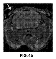
図4aおよび4bに示すように、水平型4,7Tバイオスペックシステム(horizontal 4,7°T Biospec system)(Bruker, Germany)を用いて、磁気共鳴映像法(MRI)により炎症を縦方向に追跡調査した。このシステムは、最大強度950mT/mおよび立ち上がり時間80μmが可能な6cmのグラジエントインサート(gradient insert)を備えている。マウスは、空気中で混合した1.5〜2%イソフルオラン(Centravet, La Palisse,France)で麻酔し、磁石中にうつ伏せで置き、頭部をNMRコイルの中心に置いた。TrueFISPシークエンスにより3D画像を撮影した:TE/TR=3.2/6.4ms、フリップ角:65°、FOV:30×18×18mm、マトリックス:256×96×96、解像度:117×188×188μm、スライス方向:冠状断、受信バンド幅:195Hz/pixel。平均値の合計数は、24(6 per l magnitude images)に等しく、合計取込時間は、23分26秒であった。 Inflammation is longitudinally tracked by magnetic resonance imaging (MRI) using a horizontal 4,7 ° T Biospec system (Bruker, Germany) as shown in FIGS. 4a and 4b. investigated. The system is equipped with a 6 cm gradient insert capable of a maximum strength of 950 mT / m and a rise time of 80 μm. Mice were anesthetized with 1.5-2% isofluorane (Centravet, La Palisse, France) mixed in air, placed prone in a magnet and the head placed in the center of the NMR coil. 3D images were taken with a TrueFISP sequence: TE / TR = 3.2 / 6.4 ms, flip angle: 65 °, FOV: 30 × 18 × 18 mm, matrix: 256 × 96 × 96, resolution: 117 × 188 × 188 μm Slice direction: coronal cut, reception bandwidth: 195 Hz / pixel. The total number of average values was equal to 24 (6 per l magnitude images) and the total capture time was 23 minutes 26 seconds.
高圧二酸化炭素への暴露により1週間後に3匹の動物個体を犠牲にし、残る3匹は1か月後に犠牲にした。頭蓋骨および脳を塊状に採取し、脱塩組織切片とした。すなわち、サンプルを12時間脱塩(Decalcifiant osseux BAYER, ref 70033, France)し、次にエタノール(70%、80%、95%、100%)中で脱水し、パラフィンに包埋した。10ミクロンの冠状切片を切り取り、ヘマトキシリン−エオジン−サフラン(Hematoxylin-Eosin-Saffron(HES))で染色し、顕微鏡写真機(Nikon eclipse 80i,The Netherlands)で観察した。切片について、脳/頭蓋骨界面での炎症の有無を観察した。 Three animals were sacrificed after one week by exposure to high pressure carbon dioxide, and the remaining three were sacrificed after one month. The skull and brain were collected in a lump and desalted tissue sections. That is, samples were desalted (Decalcifiant osseux BAYER, ref 70033, France) for 12 hours, then dehydrated in ethanol (70%, 80%, 95%, 100%) and embedded in paraffin. Ten micron coronal sections were cut and stained with Hematoxylin-Eosin-Saffron (HES) and observed with a micrograph (Nikon eclipse 80i, The Netherlands). The sections were observed for inflammation at the brain / skull interface.
マウス頭蓋冠欠損でのインビボプリンティング
インビボ実験を行うため、図3に示すように、マウスを受容するように構成された保持装置にマウスを設置し、頭蓋冠欠損がリボンを向くように位置合わせした。
In vivo printing with a mouse calvarial defect As shown in FIG. 3, the mouse was placed on a holding device configured to receive the mouse and aligned so that the calvarial defect was facing the ribbon, as shown in FIG. .
その結果、プリンティング法を以下のように行った:
・マウスを保持部に設置し、次にステーション内の(x、y、z)電動式平行移動ステージ上に導入した。
・ビデオシステム(すなわち、瞬間表示装置を有するCCDカメラ)を使用して頭蓋冠欠損を可視化し、マウス保持部をz軸に対して平行移動させることにより焦点を合わせた。実際、硬膜表面をz軸に沿った基材の位置としてソフトに記録した。このz位置は、基材の物理的位置としてソフトに記録した。次に、タッチスクリーンを通して(x、y)軸に沿ってマウス保持部を平行移動させて、右側の欠損の中央を対象とした。次に、この位置をプリントパターンの起点として記録した。
・ソフトによりパターン(直径3mmの円板)をコンピューター処理し、レーザーパラメーター(出力、周波数)、走査速度およびプリント間隙距離をパターンと組み合わせた。この研究の枠組みにおいて、事前に行ったn−HAのレーザープリンティングについての研究と同じように、レーザーエネルギーは12μJ/パルス(40μmスポットサイズ)、周波数は5kHz、走査速度は200mm/s、およびプリント間隙は1500μmであった。
・このパターンを30回再現することにより、3Dプリンティングを行なった。各パターンの間において、保持部を、リボン上にプリントされた二つのパターンの間の距離と等しくした任意の距離に基づき、自動的に移動させた。層を追加する前に、マウス保持部を20μm下げた。これは、n−HAの一層の厚さに対応するものである。
・プロセスの最後に、マウスとリボンとの間の接触を避けるために、保持部を適当な距離に下げる。
As a result, the printing method was performed as follows:
A mouse was placed on the holding unit and then introduced on the (x, y, z) motorized translation stage in the station.
A video system (ie a CCD camera with a momentary display) was used to visualize the calvarial defect and focused by translating the mouse holder relative to the z-axis. In fact, the dura surface was softly recorded as the position of the substrate along the z-axis. This z position was recorded softly as the physical position of the substrate. Next, the mouse holding part was translated along the (x, y) axis through the touch screen, and the center of the defect on the right side was targeted. Next, this position was recorded as the starting point of the print pattern.
-The pattern (3mm diameter disc) was processed by software and the laser parameters (output, frequency), scanning speed and print gap distance were combined with the pattern. In the framework of this study, the laser energy is 12 μJ / pulse (40 μm spot size), the frequency is 5 kHz, the scanning speed is 200 mm / s, and the print gap, as in the previous research on laser printing of n-HA. Was 1500 μm.
-3D printing was performed by reproducing this pattern 30 times. Between each pattern, the holder was automatically moved based on an arbitrary distance equal to the distance between the two patterns printed on the ribbon. Before adding the layer, the mouse holding part was lowered by 20 μm. This corresponds to the thickness of one layer of n-HA.
• At the end of the process, lower the holding part to an appropriate distance to avoid contact between the mouse and the ribbon.
この1群は、雄のOF1マウス(12週齢)を30匹含んでいた。頭蓋冠骨欠損を発生させた後、各動物個体に対して、同量の材料を与えた。この材料は、HT Bio−LPにより左側の欠損(試験部位)にプリントされた30層のn−HA(各層20μm)からなる積層であった。対照側部(右側)の欠損は、陰性対照(対照部位)として欠損したまま残した。次に、皮膚を縫合し、動物個体を動物施設に戻した。 This group contained 30 male OF1 mice (12 weeks of age). After the development of a calvarial bone defect, the same amount of material was given to each animal individual. This material was a laminate consisting of 30 layers of n-HA (each layer 20 μm) printed on the left defect (test site) by HT Bio-LP. The defect on the control side (right side) was left missing as a negative control (control site). The skin was then sutured and the animal individual was returned to the animal facility.
3か月の群に属する2匹の動物個体に対して、7日目、15日目および30日目に、MRIを非侵襲法として使用して脳の炎症をインビボで縦方向に評価した。この研究で使用したパラメーターは、上記と同様であった。
Brain inflammation was assessed longitudinally in vivo using MRI as a non-invasive method on
n−HA追跡調査および新しい骨の形成に関し、1週間後(マウスの数n=10)、1か月後(n=10)または3か月後(n=10)に、高圧二酸化炭素への暴露によりマウスを犠牲にし、頭部全体を“塊”として切除し、4%PFA中で3日間固定した。General Electric μCTを使用したX線マイクロトモグラフィーにより、全てのサンプルについてデータを取得した。X線発生のために使用した電圧および強度は、それぞれ80kVおよび60mAであった。暴露時間3000msで800枚の画像を得た。得られた解像度は、0.015mmであった。Image J Softwareを用いて、骨欠損の再構築されなかった表面を評価した。Medcalc(登録商標)software(Belgium)を用いて、統計分析を行った。三つの独立した群(非対サンプル:1週間、1か月および3か月)を、ノンパラメトリックなマン−ホイットニー(Mann-Whitney)のU−検定により比較した。p<0.05の場合、有意な差異とみなした。 For n-HA follow-up and new bone formation, after 1 week (number of mice n = 10), 1 month (n = 10) or 3 months (n = 10), The mice were sacrificed by exposure and the entire head was excised as a “chunk” and fixed in 4% PFA for 3 days. Data were acquired for all samples by X-ray microtomography using General Electric μCT. The voltage and intensity used for X-ray generation were 80 kV and 60 mA, respectively. 800 images were obtained with an exposure time of 3000 ms. The resolution obtained was 0.015 mm. Image J Software was used to assess the unreconstructed surface of the bone defect. Statistical analysis was performed using Medcalc® software (Belgium). Three independent groups (unpaired samples: 1 week, 1 month and 3 months) were compared by non-parametric Mann-Whitney U-test. A p <0.05 was considered a significant difference.
最後に、各群のサンプル三つを、組織を調べるために脱塩した。脱灰切片を上記のように調製し、ヘマトキシリン−エオジン−サフラン(Hematoxylin-Eosin-Saffron(HES))で染色し、n−HAおよび新たに形成された骨の有無を調べるために顕微鏡写真機(Nikon eclipse 80i, The Netherlands)で観察した。 Finally, three samples from each group were desalted to examine the tissue. Demineralized sections were prepared as described above, stained with Hematoxylin-Eosin-Saffron (HES), and micrographs (in order to check for the presence of n-HA and newly formed bone) Nikon eclipse 80i, The Netherlands).
結果および考察
生きたマウスに形成された重篤サイズの頭蓋冠欠損にn−HAをプリントする根拠
上記動物モデルを、インビボでのバイオプリンティングの可能性を評価するために保存した。外傷を負わせる可能性のあるプロセスであるにもかかわらず、ほとんどの動物個体は早期に回復し、感染や神経障害の兆候を全く示さなかった。
Results and Discussion
Rationale for printing n-HA on severe sized calvarial defects formed in living mice The animal model was stored to evaluate the potential for bioprinting in vivo. Despite a potentially traumatic process, most animal individuals recovered early and showed no signs of infection or neuropathy.
本発明のHT Bio−LPステーションを用いて、n−HAのインビボプリンティングを行った。 In vivo printing of n-HA was performed using the HT Bio-LP station of the present invention.
ヒドロキシアパタイトは、骨の非有機成分であるため、これを選択した。 Hydroxyapatite was chosen because it is a non-organic component of bone.
暫定的結果として、30匹の雄マウスのうち、29匹が、一連の外科処置、さらにレーザープリンティング実験を含む全プロセスの後に回復した。手術およびn−HAプリンティング後に創感染または神経障害を発症した動物個体はなかった。さらに、骨欠損を形成した後、硬膜の一体性を調べた。すなわち、脈動する血管の存在を確認することにより硬膜の一体性を確認した。 As a tentative result, 29 out of 30 male mice recovered after the entire process, including a series of surgical procedures, as well as laser printing experiments. None of the animals developed wound infection or neuropathy after surgery and n-HA printing. Furthermore, after forming a bone defect, the integrity of the dura mater was examined. That is, the integrity of the dura mater was confirmed by confirming the presence of pulsating blood vessels.
マウスの脳に対する近赤外レーザー照射の効果
248nmおよび355nmのUVパルスレーザーを用いるレーザー援用バイオプリンティングが広く研究されているが、近赤外レーザーパルスは生体組織に無害であると想定されているため、1064nmで発光するナノ秒パルスレーザーを用いた。
Effects of near-infrared laser irradiation on mouse brain Laser-assisted bioprinting using 248 nm and 355 nm UV pulse lasers has been extensively studied, but near-infrared laser pulses are assumed to be harmless to living tissue. , A nanosecond pulsed laser emitting at 1064 nm was used.
プリンティング実験と同様の暴露を用いて、6匹のマウスの硬膜に対して、レーザーを直接照射した。 Using the same exposure as in the printing experiment, the dura of 6 mice was directly irradiated with laser.
図4aおよび4bに示すように、MRI分析により、レーザー効果および外科処置による外傷について、7日目の時点で試験した側の硬膜の下にあった浮腫が、15日目で退行し、21日後に消滅したことが示された。脱灰切片において、試験欠損および対照欠損の両方で筋線維芽細胞が見られ、神経および骨組織の炎症または壊死はなかった(図5)。これらの実験に基づき、この実験で用いた赤外レーザーは、研究に使用した脳組織に対して有害な作用がないことが結論付けられた。
As shown in FIGS. 4a and 4b, by MRI analysis, the edema that was under the dura on the side tested at day 7 for laser effects and surgical trauma regressed on
頭蓋冠欠損内におけるインビボでのn−HAプリンティングおよび骨の修復
頭蓋冠欠損内でのn−HAプリンティングに関し、実験の最後に行った肉眼検査により、プリントされた材料が、コンピューター描画したパターンの形状に応じて存在することが確認された。さらに、プリントされた材料の化学的および生物学的物性は、レーザープリンティングにより変質していなかった。
For in vivo n-HA printing in calvarial defects and bone repair for n-HA printing in calvarial defects, the material printed by the macroscopic examination performed at the end of the experiment shows the shape of the computer-drawn pattern It was confirmed that it existed according to Moreover, the chemical and biological properties of the printed material were not altered by laser printing.
n−HAプリンティングを施した動物個体における脳の炎症をMRIで追跡したところ、事前にレーザー照射して得たサンプル(上記参照)と同じ炎症強度が示された。この結果より、n−HAのレーザープリンティング自体は、マウスの脳に有害な作用を引き起こさない。 When brain inflammation in an animal individual subjected to n-HA printing was followed by MRI, the same inflammation intensity as the sample obtained by laser irradiation in advance (see above) was shown. From this result, laser printing of n-HA itself does not cause harmful effects on the mouse brain.
脱灰組織切片について、マイクロコンピュータートモグラフィーにより、三つの時点(1週間後10匹のマウス、1か月後10匹のマウス、および3か月後10匹のマウス)において骨の修復を縦方向に分析した。 For decalcified tissue sections, bone repair was longitudinally performed at three time points (10 mice after 1 week, 10 mice after 1 month, and 10 mice after 3 months) by microcomputer tomography. analyzed.
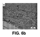
1週間後の脱灰切片では、材料が試験部位の硬膜と近接して存在していた(図6a)。1か月後では、新たに形成された成熟骨および未成熟骨、ならびにマクロファージ内のn−HA凝集物が試験部位に観察された(図6c)。一方、対照部位では骨の修復は見られなかった(図6d)。プリンティングから3か月後では、成熟骨組織が試験部位に観察された(図6e)。対照部位(図6f)では、骨の修復は多くの場合、未完全なままであった。さらに、1週間後から3か月後まで、インサイチュで観察されたn−HA粒子の量が減少した。これは、材料が骨の再構築化に取り込まれたこと、または、間質液への溶解および炎症細胞による貪食が原因と考えられる。 In the decalcified section after 1 week, material was present in close proximity to the dura mater at the test site (FIG. 6a). After one month, newly formed mature and immature bones and n-HA aggregates in macrophages were observed at the test site (FIG. 6c). On the other hand, no bone repair was seen at the control site (FIG. 6d). Three months after printing, mature bone tissue was observed at the test site (FIG. 6e). At the control site (FIG. 6f), bone repair often remained incomplete. Furthermore, the amount of n-HA particles observed in situ decreased from 1 week to 3 months later. This may be due to the material being taken up by bone remodeling or lysis into interstitial fluid and phagocytosis by inflammatory cells.
これらの結果は、X線マイクロトモグラフィー分析により確認した。図8aおよび8bに示すように、プリンティングから1か月後で骨の形成がはっきりと観察された。再構築されていない表面は、1か月後の時点で1週間後と比較して有意に低く(p<0.05)、3か月後の時点で1か月後と比較して有意に低く(p<0.01)、3か月後の時点で1週間後と比較して有意に低い(p<0.01)。さらに、陰性対照部位では、いずれの時点においても骨の形成は起こらなかった。 These results were confirmed by X-ray microtomography analysis. As shown in FIGS. 8a and 8b, bone formation was clearly observed one month after printing. The unreconstructed surface was significantly lower at 1 month after 1 week (p <0.05) and significantly after 3 months compared with 1 month. Low (p <0.01) and significantly lower (p <0.01) after 3 months compared to 1 week. Furthermore, no bone formation occurred at any time point in the negative control site.
一部の場合において、プリンティング実験に関係しなかった領域である対照側部欠損においてもn−HA材料が観察された。図6bに示すように、n−HAは、脳表面(対照部位、頭蓋冠正中線)から離れた位置で観察することができる。これらのn−HA粒子は、プリントされた材料が受容部位へと固定化されなかったために、プリントされた部位から移動していた可能性がある。よって、縫合の際、および動物個体の回復後に皮膚に加えられた圧力により、プリントされたn−HAが、プリントされた欠損から対照側部へ移動する現象を誘発した可能性がある。将来、プリントされた材料の固定化およびマウス皮膚の縫合に特定の関心が向けられるであろう。この目的のため、外科用接着剤または他の生体膜を使用することが想定される。 In some cases, n-HA material was also observed in the control side defect, a region that was not relevant to the printing experiment. As shown in FIG. 6b, n-HA can be observed at a position away from the brain surface (control site, calvarial midline). These n-HA particles may have migrated from the printed site because the printed material was not immobilized to the receiving site. Thus, the pressure applied to the skin during suturing and after recovery of the animal individual may have induced the phenomenon of printed n-HA moving from the printed defect to the control side. In the future, particular interest will be directed to immobilization of the printed material and suture of the mouse skin. For this purpose, it is envisaged to use a surgical adhesive or other biological membrane.
結論および展望
高性能レーザー援用バイオプリンティングに特化したCAD−CAMステーションを用いて、ナノ−ヒドロキシアパタイトのインビボバイオプリンティングを行った。これらの結果により、インビボプリンティングが可能であることが示され、将来、医療ロボット工学およびコンピューター援用医療介入において有用であることが証明される可能性がある。
Conclusions and prospects In vivo bioprinting of nano-hydroxyapatite was performed using a CAD-CAM station dedicated to high performance laser-assisted bioprinting. These results indicate that in vivo printing is possible and may prove useful in future in medical robotics and computer-assisted medical interventions.
バイオプリンティング機能を有する医療ロボットを改良することにより、まず、外科手術の精度を向上させることが可能になると考えられる。実際、体内において材料または薬剤をμLの体積で取り扱うことは、現在、外科医(または実際のロボット)が注射器を用いて行っているが、生物学的プリンターを使用して非常に少量の材料または薬剤を堆積させることができる。これは、生物学的プリンターがpL体積の液滴を発生させることができるからである。さらに、体積を減少させることと平行して、レーザープリンターまたは他のバイオプリンターを使用することにより、空間的解像度も大幅に改善されるであろう。 By improving a medical robot having a bioprinting function, it is considered possible to first improve the accuracy of surgery. In fact, handling a material or drug in a microliter volume in the body is currently done by a surgeon (or actual robot) using a syringe, but using a biological printer, a very small amount of material or drug Can be deposited. This is because biological printers can generate droplets of pL volume. Furthermore, in parallel with reducing the volume, using a laser printer or other bioprinter will also significantly improve the spatial resolution.
最後に、インビボバイオプリンティングがレーザー技術の独創的な使用用途となるかに関して、レーザープリンティングを他のレーザー援用プロセス(例えば、レーザー組織切除、レーザー加熱、・・・)と組み合わせることで、ロボット製造業者、したがって臨床医に対しても新たな展望が開かれるであろう。 Finally, robot manufacturers can combine laser printing with other laser-assisted processes (eg, laser tissue ablation, laser heating, ...) as to whether in vivo bioprinting will be a unique application for laser technology. Therefore, a new perspective will open to clinicians.
第2の実験
図9〜11に関連して記載される第2の実験では、ルシフェラーゼ酵素で形質転換したMG63細胞(MG63−Luc)を生体物質として、正中線マウス頭蓋冠欠損内にインビボプリンティングを行う。
Second Experiment In a second experiment described in connection with FIGS. 9-11, MG63 cells transformed with luciferase enzyme (MG63-Luc) were used as biological material for in vivo printing in the midline mouse calvarial defect. Do.
材料および方法
プリント可能なMG63−Lucの合成
この実験において、生体物質として、ルシフェラーゼ酵素で形質転換したMG63細胞(MG63−Luc)の溶液を堆積させた。細胞濃度は5000万個/mlであり、細胞は0.5%アルギン酸塩(v/v)を添加した培地に懸濁させた。
Materials and methods
Synthesis of printable MG63-Luc In this experiment, a solution of MG63 cells (MG63-Luc) transformed with luciferase enzyme was deposited as biological material. The cell concentration was 50 million cells / ml, and the cells were suspended in a medium supplemented with 0.5% alginate (v / v).
マウスにおける重篤サイズの頭蓋冠欠損の作成
この場合、直径トレフィンバー(diameter trephine burr)(TBR Toulouse,France)を用いて、ヌードマウス(Charles River,France)に4mm幅の正中線頭蓋冠欠損を形成した(図9参照)。動物個体の準備は、上記と同様の手順である。
Creating a severely sized calvarial defect in a mouse In this case, using a diameter trephine burr (TBR Toulouse, France), a nude mouse (Charles River, France) was given a 4 mm wide midline calvarial defect. Formed (see FIG. 9). The preparation of the animal individual is the same procedure as described above.
マウス頭蓋冠欠損でのインビボプリンティング
上記生物学的プリンティングステーション1を使用し、支持体を覆う生体物質層以外は第1の実験に関して記載したものと同様のリボンを調製した。
In vivo printing with mouse calvarial defects The biological printing station 1 described above was used to prepare a ribbon similar to that described for the first experiment except for the biological material layer covering the support.
受容基材3としてのマウスを、位置合わせシステムに置き(図9)、対象領域としての正中線頭蓋冠欠損を保持装置の開放作業領域およびCCDカメラに向けた。
The mouse as the receiving
欠損のビデオキャプチャーを示す図10から分かるように、生物学的プリンティングステーションの撮像システムのCCDカメラにより、欠損を検出した。 As can be seen from FIG. 10, which shows a video capture of the defect, the defect was detected by the CCD camera of the imaging system of the biological printing station.
欠損の形態に応じて、3mm径の環状パターンに決定した。環の中央を、欠損の中央に調節した。 It was determined to be a 3 mm diameter annular pattern depending on the form of the defect. The center of the ring was adjusted to the center of the defect.
結果および考察
バイオプリンティング直後に行った肉眼検査により、MG63細胞の円が見られた。
Results and Discussion A circle of MG63 cells was seen by macroscopic examination performed immediately after bioprinting.
さらに、ルシフェリン(Luciferin)を腹腔内に注射して光子撮像(Biospace, France)分析を行った。光子撮像装置で速やかに観察した結果を図11に示す。同図より、予め撮像システムで決定した位置にMG63細胞の環状パターンが存在することが証明された。 In addition, Luciferin was injected intraperitoneally to perform photon imaging (Biospace, France) analysis. The results of quick observation with a photon imaging device are shown in FIG. From this figure, it was proved that a circular pattern of MG63 cells exists at a position determined in advance by the imaging system.
この実験は、インビボでの細胞のプリンティングが実施可能であることを示している。 This experiment shows that cell printing in vivo is feasible.
第3の実験
図12に関連して示される第3の実験では、ルシフェラーゼ酵素で形質転換したマウス間充織幹細胞(ATCCから購入したD1細胞株)を生体物質(D1−Luc)として用いて、マウス頭蓋冠側部欠損でのインビボプリンティングを行う。
Third Experiment In a third experiment shown in connection with FIG. 12, mouse mesenchymal stem cells transformed with luciferase enzyme (D1 cell line purchased from ATCC) were used as biological material (D1-Luc), In vivo printing is performed on mouse calvarial lateral defects.
材料および方法
プリント可能なD1−Luc溶液の調製
この実験において、ルシフェラーゼ酵素で形質転換したD1細胞(D1−Luc)の溶液を生体物質として堆積させた。細胞濃度は5000万個/mlであり、1%アルギン酸塩(v/v)を添加した培地に細胞を懸濁させた。
Materials and methods
Preparation of printable D1-Luc solution In this experiment, a solution of D1 cells transformed with luciferase enzyme (D1-Luc) was deposited as biological material. The cell concentration was 50 million cells / ml, and the cells were suspended in a medium supplemented with 1% alginate (v / v).
マウスにおける重篤サイズの頭蓋冠欠損の作成
この場合、直径トレフィンバー(TBR Toulouse, France)を用いて、Balb/c(Charles River, France)に3.3mm幅の頭蓋冠側部欠損を二つ形成した。動物個体の準備は、上記と同様の手順ある。
Creation of severe-sized calvarial defects in mice In this case, two 3.3 mm wide calvarial lateral defects were created in Balb / c (Charles River, France) using a diameter trephine bar (TBR Toulouse, France). Formed. The preparation of the animal individual has the same procedure as described above.
マウス頭蓋冠欠損でのインビボプリンティング
上記生物学的プリンティングステーション1を使用し、支持体を覆う生体物質層以外は第2の実験に関して記載したものと同様のリボンを調製した。
In vivo printing with a mouse calvarial defect Using the biological printing station 1 described above, a ribbon similar to that described for the second experiment was prepared except for the biological material layer covering the support.
受容基材3としてのマウスを、位置合わせシステムに置き、対象領域としての一方の頭蓋冠側部欠損を保持装置の開放作業領域およびCCDカメラに向けた。
The mouse as the receiving
生物学的プリンティングステーションの撮像システムのCCDカメラにより、欠損を検出した。 Defects were detected by the CCD camera of the imaging system of the biological printing station.
欠損の形態に応じて、環状パターンを以下のように決定した:外径:3.2mm、内径:2.8mm。環の中央を、欠損の中央に調節した。 Depending on the form of the defect, the annular pattern was determined as follows: outer diameter: 3.2 mm, inner diameter: 2.8 mm. The center of the ring was adjusted to the center of the defect.
結果および考察
光子撮像装置(Biospace, France)を使用して、インビボでの細胞増殖をバイオプリンティングから3週間後まで追跡した。図12に示すように、間充織幹細胞は、バイオプリンティングから21日後まで増殖する。
Results and Discussion Cell growth in vivo was followed up to 3 weeks after bioprinting using a photon imaging device (Biospace, France). As shown in FIG. 12, mesenchymal stem cells proliferate until 21 days after bioprinting.
Claims (18)
堆積させる生体物質(2)を供給するように構成された少なくとも一つの生体物質供給装置(6、7、8)、および
基材(3)を受容し、対象領域(3a)を供給装置(6、7、8)に対して位置合わせするように構成された位置合わせシステム、
を含むものである、バイオプリンティング装置(4)と、
− 堆積させるパターンに応じて供給装置(6、7、8)および前記位置合わせシステムを互いに対して駆動するように構成された電子制御部(5)と、
を含むバイオプリンティングステーション(1)であって、
バイオプリンティングステーション(1)が、基材(3)の画像を得るように、および得られた画像上に非対象領域(3b)に対する対象領域(3a)の特徴を認識可能に表示するように構成された撮像システム(15)を含み、得られた基材(3)の画像が、得られた画像上に認識可能に表示された対象領域(3a)を検出して、得られた画像上に検出された対象領域(3a)に対応するパターンを決定するように処理されることを特徴とするバイオプリンティングステーション(1)。 A bioprinting device (4) configured to deposit a pattern of biological material (2) on a target region (3a) of a substrate (3), the target region (3a) ) And the non-target region (3b) of the substrate (3), the bioprinting device (4)
At least one biological material supply device (6, 7, 8) configured to supply the biological material (2) to be deposited, and the substrate (3), and the target region (3a) is supplied to the supply device (6 , 7, 8) an alignment system configured to align with
A bioprinting device (4), including:
An electronic control unit (5) configured to drive the supply device (6, 7, 8) and the alignment system relative to each other according to the pattern to be deposited;
A bioprinting station (1) comprising:
The bio-printing station (1) is configured to obtain an image of the base material (3) and to display recognizable features of the target area (3a) with respect to the non-target area (3b) on the obtained image. A target area (3a) that is recognizable and displayed on the obtained image by detecting the target region (3a) on the obtained image. Bioprinting station (1), characterized in that it is processed to determine a pattern corresponding to the detected target area (3a).
請求項1に記載のバイオプリンティングステーション(1)。 The electronic control unit (5) processed the image of the obtained base material (3), and automatically detected the target area (3a) displayed recognizable on the obtained image, and obtained It is configured to automatically determine a pattern corresponding to the target area (3a) detected on the image,
The bioprinting station (1) according to claim 1.
請求項2に記載のバイオプリンティングステーション(1)。 The electronic control unit (5) determines the position of the target area (3a) in the reference frame of the bioprinting station (1), and the supply device (6, 7, 8) and the alignment system according to the determined position Are configured to drive relative to each other,
The bioprinting station (1) according to claim 2.
請求項2または3に記載のバイオプリンティングステーション(1)。 The electronic control unit (5) is configured to drive the imaging system (15) according to the light path corresponding to the pattern determined to be deposited.
The bioprinting station (1) according to claim 2 or 3.
−生体物質(2)を含有する少なくとも一つのリボン(6)を保持するための保持装置(7)であって、リボン(6)の少なくとも一部を受容するように構成された少なくとも一つの開放作業空間(7a)を備えており、この開放作業空間(7a)が対象領域(3a)を向くように電子制御部(5)がこの保持装置(7)および前記位置合わせシステムを互いに対して駆動するように構成されている、保持装置(7)、
−レーザー光(9)を発光するために配置されたレーザーシステム(8)であって、生体物質(2)をリボン(6)から基材(3)へ転写させるように構成されており、電子制御部(5)が、決定されたパターンに応じて開放作業空間(7a)内にレーザー光(9)を向けるようにこのレーザーシステム(8)を駆動するように構成されている、レーザーシステム(8)、を含む、
請求項1〜4のいずれかに記載のバイオプリンティングステーション(1)。 The supply device is
A holding device (7) for holding at least one ribbon (6) containing biological material (2), at least one opening configured to receive at least part of the ribbon (6); The electronic control unit (5) drives the holding device (7) and the alignment system with respect to each other so that the work space (7a) is provided and the open work space (7a) faces the target area (3a). A holding device (7), configured to
A laser system (8) arranged to emit laser light (9), which is configured to transfer the biological material (2) from the ribbon (6) to the substrate (3); A laser system (5) configured to drive the laser system (8) so that the controller (5) directs the laser light (9) into the open work space (7a) according to the determined pattern. 8)
The bioprinting station (1) according to any one of claims 1 to 4.
請求項5に記載のバイオプリンティングステーション(1)。 A laser system (8) for emitting laser light (9) and an optical scanning device (11) configured to orient the laser light (9) in an open work space (7a). 12)
The bioprinting station (1) according to claim 5.
請求項6に記載のバイオプリンティングステーション(1)。 The laser device (10) is an infrared pulsed laser;
The bioprinting station (1) according to claim 6.
請求項5〜7のいずれかに記載のバイオプリンティングステーション(1)。 The ribbon (6) further includes a ribbon (6) received at least partially within the open working space (7a) of the holding device (7), the ribbon (6) facing the first surface (6a) towards the laser system (8). ) And a second surface (6b) with a layer of biological material (2), this second surface (6b) faces the alignment system,
The bioprinting station (1) according to any one of claims 5 to 7.
請求項8に記載のバイオプリンティングステーション(1)。 The ribbon (6) is transparent to the laser light (9), and is disposed between the support and the biological material (2) layer that is covered with the biological material (2) layer. Including a converted intermediate layer,
The bioprinting station (1) according to claim 8.
請求項1〜9のいずれかに記載のバイオプリンティングステーション(1)。 The bioprinting device (4) is configured to form a biological tissue structure by depositing a pattern of the biological material (2), and the target region is a non-target region (3b) of the base material (3). ), The undulations (3a) having a certain shape and dimensions, and the imaging system (15) has the undulations (3a) on the obtained image. The undulations displayed in a recognizable manner are detected on the obtained image, and a pattern corresponding to the shape dimension of the undulations detected on the obtained image is determined. A biological tissue structure corresponding to this undulation (3a) is formed,
The bioprinting station (1) according to any one of claims 1 to 9.
請求項10に記載のバイオプリンティングステーション(1)。 The electronic control unit (5) automatically detects the undulating portion (3a) displayed in a recognizable manner on the obtained image, and sets the shape of the undulating portion (3a) detected on the obtained image. Configured to automatically determine the corresponding pattern,
The bioprinting station (1) according to claim 10.
請求項10に従属した請求項12に記載のアセンブリ。 The target region has a undulation portion (3a) with respect to the non-target region (3b) of the base material (3), and the undulation portion (3a) has a certain shape and dimension.
An assembly according to claim 12 when dependent on claim 10.
B−少なくとも一つの対象領域(3a)、および非対象領域(3b)を呈する基材(3)(ヒトを除く)であって、対象領域(3a)が、その対象領域(3a)を非対象領域(3b)と区別する特徴を有する基材(3)を準備する工程、
C−対象領域(3a)をバイオプリンティング装置(4)に対して位置合わせする工程、
D−基材(3)の画像を得て、得られた画像上に対象領域(3a)の特徴を認識可能に表示する工程、
E−得られた基材(3)の画像を処理し、得られた画像上に認識可能に表示された対象領域(3a)を検出し、得られた画像上に検出された対象領域(3a)に対応するパターンを決定する工程、
F−決定されたパターンに応じて生体物質(2)を対象領域(3a)上に堆積させる工程、
を含むバイオプリンティング法。 A-providing a bioprinting device (4) configured to deposit a pattern of biological material (2);
B—Substrate (3) (excluding human ) presenting at least one target area (3a) and a non-target area (3b), where the target area (3a) is non-target Preparing a base material (3) having a characteristic distinguishing from the region (3b);
C—aligning the target area (3a) with respect to the bioprinting device (4),
A step of obtaining an image of the D-base material (3) and displaying the feature of the target region (3a) on the obtained image in a recognizable manner;
E—Process the image of the obtained substrate (3), detect the target area (3a) displayed recognizable on the obtained image, and detect the target area (3a) detected on the obtained image ) Determining a pattern corresponding to
F-depositing biological material (2) on the target area (3a) according to the determined pattern;
Bioprinting methods including:
請求項15に記載のバイオプリンティング法。 Step E automatically detects the target area (3a) displayed recognizable on the obtained image, and automatically detects the pattern corresponding to the target area (3a) detected on the obtained image. Including deciding,
The bioprinting method according to claim 15.
請求項15または16に記載のバイオプリンティング法。 The target region of the base material (3) has a undulation portion (3a) that is characteristic with respect to the non-target region (3b) of the base material (3), and this undulation portion (3a) has a certain shape and dimension. And the step D includes recognizable display of the undulations (3a) on the obtained image, and the step E is recognizable displayed on the obtained image. Detecting the step (3a), and determining a pattern corresponding to the shape and size of the undulations (3a) detected on the obtained image, wherein the process F corresponds to the undulations (3a). Forming a tissue structure,
The bioprinting method according to claim 15 or 16.
請求項15〜17に記載のバイオプリンティング法。 Step E further includes determining a position of the region of interest (3a), and Step F includes depositing biological material (2) at the determined position.
The bioprinting method according to claim 15.
Applications Claiming Priority (3)
| Application Number | Priority Date | Filing Date | Title |
|---|---|---|---|
| EP10305224.7 | 2010-03-04 | ||
| EP10305224 | 2010-03-04 | ||
| PCT/EP2011/053331 WO2011107599A1 (en) | 2010-03-04 | 2011-03-04 | Bioprinting station, assembly comprising such bioprinting station and bioprinting method |
Publications (3)
| Publication Number | Publication Date |
|---|---|
| JP2013521033A JP2013521033A (en) | 2013-06-10 |
| JP2013521033A5 JP2013521033A5 (en) | 2014-04-17 |
| JP5757961B2 true JP5757961B2 (en) | 2015-08-05 |
Family
ID=42950279
Family Applications (1)
| Application Number | Title | Priority Date | Filing Date |
|---|---|---|---|
| JP2012555441A Active JP5757961B2 (en) | 2010-03-04 | 2011-03-04 | Bioprinting station, assembly including the bioprinting station, and bioprinting method |
Country Status (5)
| Country | Link |
|---|---|
| US (2) | US9039998B2 (en) |
| EP (1) | EP2542659B1 (en) |
| JP (1) | JP5757961B2 (en) |
| ES (1) | ES2671594T3 (en) |
| WO (1) | WO2011107599A1 (en) |
Families Citing this family (62)
| Publication number | Priority date | Publication date | Assignee | Title |
|---|---|---|---|---|
| US8241905B2 (en) | 2004-02-24 | 2012-08-14 | The Curators Of The University Of Missouri | Self-assembling cell aggregates and methods of making engineered tissue using the same |
| WO2010008905A2 (en) | 2008-06-24 | 2010-01-21 | The Curators Of The University Of Missouri | Self-assembling multicellular bodies and methods of producing a three-dimensional biological structure using the same |
| US9149952B2 (en) | 2010-10-21 | 2015-10-06 | Organovo, Inc. | Devices, systems, and methods for the fabrication of tissue |
| AU2011329002C1 (en) | 2010-11-15 | 2017-05-25 | Accelerated Biosciences Corp. | Generation of neural stem cells from human trophoblast stem cells |
| AU2012225644B2 (en) * | 2011-03-07 | 2017-05-04 | Wake Forest University Health Sciences | Delivery system |
| WO2013023874A1 (en) * | 2011-08-16 | 2013-02-21 | Asml Netherlands B.V. | Lithographic apparatus, programmable patterning device and lithographic method |
| GB201119032D0 (en) | 2011-11-03 | 2011-12-14 | Isis Innovation | Multisomes: encapsulated droplet networks |
| US9499779B2 (en) * | 2012-04-20 | 2016-11-22 | Organovo, Inc. | Devices, systems, and methods for the fabrication of tissue utilizing UV cross-linking |
| US10668762B2 (en) * | 2012-10-21 | 2020-06-02 | Precise Bio Inc. | Multi-technology printing system |
| EP2909034A4 (en) * | 2012-10-21 | 2017-11-29 | Photon Jet Ltd. | A multi-technology printing system |
| GB201219196D0 (en) | 2012-10-25 | 2012-12-12 | Isis Innovation | Droplet assembly method |
| GB201219201D0 (en) | 2012-10-25 | 2012-12-12 | Isis Innovation | Hydrogel network |
| EP2731126A1 (en) | 2012-11-09 | 2014-05-14 | Nederlandse Organisatie voor toegepast -natuurwetenschappelijk onderzoek TNO | Method for bonding bare chip dies |
| CN113604423A (en) | 2012-11-30 | 2021-11-05 | 艾克塞利瑞提德生物技术公司 | Methods of differentiating stem cells by modulating MIR-124 |
| WO2014087175A2 (en) * | 2012-12-07 | 2014-06-12 | Isis Innovation Limited | Droplet assembly by 3d printing |
| JP6502857B2 (en) | 2013-01-14 | 2019-04-17 | スクリップス ヘルス | Tissue array printing |
| US9442105B2 (en) | 2013-03-15 | 2016-09-13 | Organovo, Inc. | Engineered liver tissues, arrays thereof, and methods of making the same |
| US10150258B2 (en) * | 2013-07-29 | 2018-12-11 | Carnegie Mellon University | Additive manufacturing of embedded materials |
| BR112016002149A2 (en) | 2013-07-31 | 2017-08-01 | Organovo Inc | automated fabric manufacturing methods, systems and devices |
| WO2015054577A1 (en) * | 2013-10-11 | 2015-04-16 | Advanced Solutions Life Sciences, Llc | System and workstation for the design, fabrication and assembly of bio-material constructs |
| EP3065875A4 (en) | 2013-11-04 | 2018-02-07 | University of Iowa Research Foundation | Bioprinter and methods of using same |
| EP2896717A1 (en) * | 2014-01-15 | 2015-07-22 | Nanotechplasma SARL | Laser direct synthesis and deposit of nanocomposite materials or nanostructures |
| US10512552B2 (en) | 2014-03-25 | 2019-12-24 | Biobots, Inc. | Methods, devices, and systems for the fabrication of materials and tissues utilizing electromagnetic radiation |
| CA2944723C (en) | 2014-04-04 | 2023-03-14 | Organovo, Inc. | Engineered three-dimensional breast tissue, adipose tissue, and tumor disease model |
| US9764515B2 (en) | 2014-05-01 | 2017-09-19 | Musc Foundation For Research Development | Multidispensor cartesian robotic printer |
| JP2017529877A (en) | 2014-10-06 | 2017-10-12 | オルガノボ インコーポレイテッド | Artificial kidney tissue, array thereof, and production method thereof |
| US20160122723A1 (en) | 2014-11-05 | 2016-05-05 | Organovo, Inc. | Engineered three-dimensional skin tissues, arrays thereof, and methods of making the same |
| JP6836990B2 (en) | 2014-11-26 | 2021-03-03 | アクセラレイテッド・バイオサイエンシズ・コーポレーション | Induced hepatocytes and their use |
| FR3030360B1 (en) * | 2014-12-17 | 2018-07-13 | Universite de Bordeaux | LASER PRINTING METHOD AND DEVICE FOR IMPLEMENTING SAME |
| FR3030361B1 (en) * | 2014-12-17 | 2017-01-20 | Univ Bordeaux | METHOD FOR PRINTING BIOLOGICAL ELEMENTS BY LASER AND DEVICE FOR IMPLEMENTING SAID METHOD |
| US10046091B2 (en) | 2015-03-20 | 2018-08-14 | Elwha Llc | Printing systems and related methods |
| USD760825S1 (en) | 2015-03-25 | 2016-07-05 | Biobots, Inc. | Bioprinter |
| CA2990631A1 (en) | 2015-06-23 | 2016-12-29 | Stryker Corporation | Delivery system and method for delivering material to a target site |
| KR102078602B1 (en) | 2015-07-23 | 2020-02-19 | 한국화학연구원 | Method for 3-dimensional co-culture of adipocytes with macrophages |
| US10655096B2 (en) * | 2015-07-31 | 2020-05-19 | Techshot, Inc. | Biomanufacturing system, method, and 3D bioprinting hardware in a reduced gravity environment |
| US11788042B2 (en) | 2015-07-31 | 2023-10-17 | Redwire Space Technologies, Inc. | Biomanufacturing system, method, and 3D bioprinting hardware in a reduced gravity environment |
| US11400183B2 (en) | 2015-09-04 | 2022-08-02 | The General Hospital Corporation | Three dimensional microtissue bioprinter |
| EP3640321B1 (en) | 2015-10-09 | 2022-04-06 | DEKA Products Limited Partnership | Method for generating a tissue for transplant |
| US10433921B2 (en) | 2015-12-28 | 2019-10-08 | Mako Surgical Corp. | Apparatus and methods for robot assisted bone treatment |
| US10675442B2 (en) | 2016-02-08 | 2020-06-09 | Nextern, Inc. | Robotically augmented catheter manipulation handle |
| US10888428B2 (en) | 2016-05-12 | 2021-01-12 | University Of Notre Dame Du Lac | Additive manufacturing device for biomaterials |
| JP2019520865A (en) * | 2016-05-26 | 2019-07-25 | スクリップス ヘルス | System and method for repairing a tissue defect |
| AU2017204355B2 (en) | 2016-07-08 | 2021-09-09 | Mako Surgical Corp. | Scaffold for alloprosthetic composite implant |
| US11254901B2 (en) | 2016-07-12 | 2022-02-22 | Deka Products Limited Partnership | System and method for printing tissue |
| US10345208B2 (en) | 2016-07-12 | 2019-07-09 | Deka Products Limited Partnership | System and method for applying force to a device |
| US20180033609A1 (en) * | 2016-07-28 | 2018-02-01 | QMAT, Inc. | Removal of non-cleaved/non-transferred material from donor substrate |
| US11299705B2 (en) | 2016-11-07 | 2022-04-12 | Deka Products Limited Partnership | System and method for creating tissue |
| CA3043791A1 (en) * | 2016-11-23 | 2018-05-31 | Institut National De La Recherche Scientifique | Method and system of laser-driven impact acceleration |
| FR3063931B1 (en) * | 2017-03-15 | 2019-03-22 | Poietis | EQUIPMENT AND METHOD FOR ADDITIVE PRINTING |
| FR3063930B1 (en) | 2017-03-15 | 2019-03-22 | Poietis | BIOIMPRESSION PROCESS |
| FR3063932B1 (en) * | 2017-03-15 | 2019-03-22 | Universite de Bordeaux | EQUIPMENT AND METHOD FOR PARTICLE DEPOSITION ON A TARGET |
| US10570362B2 (en) | 2017-07-12 | 2020-02-25 | Deka Products Limited Partnership | System and method for transferring tissue |
| DE102018005010A1 (en) * | 2017-07-13 | 2019-01-17 | Wika Alexander Wiegand Se & Co. Kg | Transfer and melting of layers |
| WO2019034954A1 (en) * | 2017-08-17 | 2019-02-21 | Clear-Cut Medical Ltd. | Tissue marking system |
| SE1850073A1 (en) * | 2018-01-24 | 2019-07-25 | Cellink Ab | 3D bioprinters |
| FR3082123B1 (en) | 2018-06-07 | 2020-10-16 | Urgo Rech Innovation Et Developpement | CELLULARIZED DRESSING AND ITS MANUFACTURING PROCESS |
| FR3087703B1 (en) * | 2018-10-25 | 2020-12-04 | Poietis | ROBOTIZED BIO-PRINTING SYSTEM |
| WO2020097083A1 (en) * | 2018-11-06 | 2020-05-14 | Cellino Biotech, Inc. | Systems for cell control |
| EP3670665A1 (en) | 2018-12-20 | 2020-06-24 | Hochschule Für Angewandte Wissenschaften München | Laser-induced cell transfer and sorting |
| EP3983200B1 (en) * | 2019-06-14 | 2023-07-12 | IO Tech Group Ltd. | Additive manufacturing of a free form object made of multicomponent materials |
| US20220040377A1 (en) * | 2020-08-06 | 2022-02-10 | PhosPrint P.C. | Laser ablation/removal and laser induced forward transfer of biological material |
| GR1010614B (en) * | 2023-01-27 | 2024-01-23 | Εθνικο Μετσοβιο Πολυτεχνειο, | Laser-induced forward transfer technique and application method threof |
Family Cites Families (10)
| Publication number | Priority date | Publication date | Assignee | Title |
|---|---|---|---|---|
| US6849462B1 (en) * | 1991-11-22 | 2005-02-01 | Affymetrix, Inc. | Combinatorial strategies for polymer synthesis |
| US6177151B1 (en) * | 1999-01-27 | 2001-01-23 | The United States Of America As Represented By The Secretary Of The Navy | Matrix assisted pulsed laser evaporation direct write |
| AU3289202A (en) * | 2000-10-24 | 2002-05-21 | Oncosis Llp | Method and device for selectively targeting cells within a three -dimensional specimen |
| US6835426B2 (en) * | 2001-01-19 | 2004-12-28 | Potomac Photonics, Inc. | Method and apparatus for pulse-position synchronization in miniature structures manufacturing processes |
| GR1004059B (en) * | 2001-12-31 | 2002-11-15 | Ιωαννα Ζεργιωτη | Fabrication of biopolymer patterns by means of laser transfer |
| DE10236029A1 (en) * | 2002-08-02 | 2004-02-19 | Cybio Systems Gmbh | Device for dispensing and monitoring the luminescence of individual samples in multi-sample arrangements |
| JP2004202126A (en) * | 2002-12-26 | 2004-07-22 | Next:Kk | Method for forming artificial bone |
| US7381440B2 (en) * | 2003-06-06 | 2008-06-03 | The United States Of America As Represented By The Secretary Of The Navy | Biological laser printing for tissue microdissection via indirect photon-biomaterial interactions |
| DE102004021904B4 (en) * | 2004-05-04 | 2011-08-18 | Carl Zeiss Microlmaging GmbH, 07745 | Method and device for generating an analysis arrangement with discrete, separate measurement ranges for biological, biochemical or chemical analysis |
| WO2011085225A1 (en) | 2010-01-08 | 2011-07-14 | Wake Forest University Health Sciences | Delivery system |
-
2011
- 2011-03-04 US US13/582,145 patent/US9039998B2/en active Active
- 2011-03-04 EP EP11707159.7A patent/EP2542659B1/en active Active
- 2011-03-04 ES ES11707159.7T patent/ES2671594T3/en active Active
- 2011-03-04 JP JP2012555441A patent/JP5757961B2/en active Active
- 2011-03-04 WO PCT/EP2011/053331 patent/WO2011107599A1/en active Application Filing
-
2015
- 2015-04-22 US US14/692,821 patent/US9629989B2/en active Active
Also Published As
| Publication number | Publication date |
|---|---|
| WO2011107599A1 (en) | 2011-09-09 |
| US9039998B2 (en) | 2015-05-26 |
| JP2013521033A (en) | 2013-06-10 |
| US9629989B2 (en) | 2017-04-25 |
| ES2671594T3 (en) | 2018-06-07 |
| US20150224291A1 (en) | 2015-08-13 |
| EP2542659B1 (en) | 2018-03-07 |
| EP2542659A1 (en) | 2013-01-09 |
| US20130017564A1 (en) | 2013-01-17 |
Similar Documents
| Publication | Publication Date | Title |
|---|---|---|
| JP5757961B2 (en) | Bioprinting station, assembly including the bioprinting station, and bioprinting method | |
| Keriquel et al. | In vivo bioprinting for computer-and robotic-assisted medical intervention: preliminary study in mice | |
| Choudhury et al. | The arrival of commercial bioprinters–Towards 3D bioprinting revolution! | |
| Leberfinger et al. | Bioprinting functional tissues | |
| Liao et al. | A material odyssey for 3D nano/microstructures: two photon polymerization based nanolithography in bioapplications | |
| Datta et al. | Essential steps in bioprinting: From pre-to post-bioprinting | |
| Zhang et al. | Tissue engineering applications of three-dimensional bioprinting | |
| Ozbolat et al. | Evaluation of bioprinter technologies | |
| Murphy et al. | 3D bioprinting of tissues and organs | |
| Colaco et al. | The potential of 3D printing in urological research and patient care | |
| JP2017514643A (en) | Methods, devices and systems for the production of materials and tissues utilizing electromagnetic radiation | |
| WO2017184839A1 (en) | Systems and methods for in vivo multi-material bioprinting | |
| EP3018531A1 (en) | Method and device for creating a three-dimensional multi-cell object | |
| JP2022507083A (en) | Compositions and Methods for Printing Tertiary Structure Corresponding to Biomaterials | |
| Bartolo et al. | 3D bioprinting: Materials, processes, and applications | |
| Kubanov et al. | Development of 3d bioprinting technology using modified natural and synthetic hydrogels for engineering construction of organs | |
| Yigci et al. | 3D bioprinted glioma models | |
| Park et al. | Three dimensional bioelectronic interfaces to small-scale biological systems | |
| Gao et al. | Three-dimensional printing of smart constructs using stimuli-responsive biomaterials: A future direction of precision medicine | |
| Wu et al. | 3D bioprinting in tissue and organ regeneration | |
| Hoehne et al. | Piezoelectric 3D bioprinting for ophthalmological applications: process development and viability analysis of the technology | |
| Buchberger et al. | Laser Structuring for Biomedical Applications | |
| Molina-Martínez et al. | 3D printed scaffolds: Challenges toward developing relevant cellular in vitro models | |
| Catros et al. | In vivo and in situ biofabrication by laser-assisted bioprinting | |
| Bhat | 3D printing equipment in medicine |
Legal Events
| Date | Code | Title | Description |
|---|---|---|---|
| A521 | Request for written amendment filed |
Free format text: JAPANESE INTERMEDIATE CODE: A523 Effective date: 20140228 |
|
| A621 | Written request for application examination |
Free format text: JAPANESE INTERMEDIATE CODE: A621 Effective date: 20140228 |
|
| A977 | Report on retrieval |
Free format text: JAPANESE INTERMEDIATE CODE: A971007 Effective date: 20141219 |
|
| A131 | Notification of reasons for refusal |
Free format text: JAPANESE INTERMEDIATE CODE: A131 Effective date: 20150106 |
|
| RD04 | Notification of resignation of power of attorney |
Free format text: JAPANESE INTERMEDIATE CODE: A7424 Effective date: 20150305 |
|
| A601 | Written request for extension of time |
Free format text: JAPANESE INTERMEDIATE CODE: A601 Effective date: 20150403 |
|
| A521 | Request for written amendment filed |
Free format text: JAPANESE INTERMEDIATE CODE: A523 Effective date: 20150414 |
|
| TRDD | Decision of grant or rejection written | ||
| A01 | Written decision to grant a patent or to grant a registration (utility model) |
Free format text: JAPANESE INTERMEDIATE CODE: A01 Effective date: 20150512 |
|
| A61 | First payment of annual fees (during grant procedure) |
Free format text: JAPANESE INTERMEDIATE CODE: A61 Effective date: 20150602 |
|
| R150 | Certificate of patent or registration of utility model |
Ref document number: 5757961 Country of ref document: JP Free format text: JAPANESE INTERMEDIATE CODE: R150 |
|
| R250 | Receipt of annual fees |
Free format text: JAPANESE INTERMEDIATE CODE: R250 |
|
| R250 | Receipt of annual fees |
Free format text: JAPANESE INTERMEDIATE CODE: R250 |
|
| R250 | Receipt of annual fees |
Free format text: JAPANESE INTERMEDIATE CODE: R250 |
|
| R250 | Receipt of annual fees |
Free format text: JAPANESE INTERMEDIATE CODE: R250 |
|
| R250 | Receipt of annual fees |
Free format text: JAPANESE INTERMEDIATE CODE: R250 |
|
| R250 | Receipt of annual fees |
Free format text: JAPANESE INTERMEDIATE CODE: R250 |