JP5754791B2 - Golf club head - Google Patents
Golf club head Download PDFInfo
- Publication number
- JP5754791B2 JP5754791B2 JP2008264852A JP2008264852A JP5754791B2 JP 5754791 B2 JP5754791 B2 JP 5754791B2 JP 2008264852 A JP2008264852 A JP 2008264852A JP 2008264852 A JP2008264852 A JP 2008264852A JP 5754791 B2 JP5754791 B2 JP 5754791B2
- Authority
- JP
- Japan
- Prior art keywords
- golf club
- club head
- axis
- range
- base point
- Prior art date
- Legal status (The legal status is an assumption and is not a legal conclusion. Google has not performed a legal analysis and makes no representation as to the accuracy of the status listed.)
- Active
Links
Images


Landscapes
- Golf Clubs (AREA)
Description
本願は、2007年9月27日出願の米国特許出願第11/863,198号の一部継続出願であり、それは、参照することによって本願に組み込まれる。
ゴルフクラブヘッドに関する他の出願および特許は、2007年10月12日出願の米国特許出願第11/871,933号、2005年2月25日出願の米国特許出願第11/067,475の継続出願である、すべてが2007年1月31に出願された、米国特許出願第11/669,891号、米国特許出願第11/669,894号、米国特許出願第11/669,900号、米国特許出願第11/669,907号、米国特許出願第11/669,910号、米国特許出願第11/669,916号、米国特許出願第11/669,920号、米国特許出願第11/669,925号、および米国特許出願第11/669,927号、2004年2月23日出願の米国特許出願第10/785,692号の一部継続出願である、現在米国特許第7,186,190号、米国特許出願第10/290,817号の一部継続出願である、現在米国特許第7,166,040号、現在米国特許第6,773,360号を含む。これらの出願は、参照することによって本願に組み込まれる。
This application is a continuation-in-part of US patent application Ser. No. 11 / 863,198, filed Sep. 27, 2007, which is incorporated herein by reference.
Other applications and patents relating to golf club heads are US patent application Ser. No. 11 / 871,933, filed Oct. 12, 2007, and US application Ser. No. 11 / 067,475, filed Feb. 25, 2005. All of which were filed on Jan. 31, 2007, U.S. Patent Application No. 11 / 669,891, U.S. Patent Application No. 11 / 669,894, U.S. Patent Application No. 11 / 669,900, U.S. Pat. No. 11 / 669,907, U.S. Patent Application No. 11 / 669,910, U.S. Patent Application No. 11 / 669,916, U.S. Patent Application No. 11 / 669,920, U.S. Patent Application No. 11/669, 925, and US patent application Ser. No. 11 / 669,927, which is a continuation-in-part of US patent application Ser. No. 10 / 785,692, filed Feb. 23, 2004. U.S. Patent No. 7,186,190, U.S. Patent Application No. 10 / 290,817, which is a continuation-in-part application, currently U.S. Patent No. 7,166,040, currently U.S. Patent No. 6,773,360 Including. These applications are incorporated herein by reference.
本願は、ゴルフクラブヘッド、より詳しくは、他の利点もあるが、打点が中心からずれた際の許容度が大きい機能を組み込んだゴルフクラブヘッドに関する。慣性モーメント、逆円錐型技術、およびクラブヘッドフェース特性の独特の組合せが記載されている。 The present application relates to a golf club head, and more particularly, to a golf club head incorporating a function having a high tolerance when the hit point is deviated from the center , although there are other advantages. Moment of inertia, inverted cone technology, and Ru unique combination is described Tei of club head face characteristics.
ゴルフクラブヘッドの製造者および設計者は、ゴルフクラブヘッドの性能を改善する方法を常に求めており、それは、美的外観を有する一方で、ゴルフクラブヘッドの許容度を有している。概して、「許容度」は、ミスヒット、すなわちゴルフクラブヘッド上のスイートスポットからずれた位置でゴルフボールを打つことによるゴルフボールの飛球線および飛距離への影響を少なくするゴルフクラブヘッドの能力として定義することができる。 Manufacturers and designers of the golf club head is constantly seeking ways to improve the performance of the golf club head, it, while having an aesthetic appearance, and has a tolerance of the golf club head. In general, "tolerance" is, miss-hit, ie the ability of the golf club head to reduce the influence of the golf ball flying line and flying distance of the ball due to the fact that hitting a golf ball at a position deviated from the sweet spot on the golf club head Can be defined as
ゴルフクラブヘッドの性能は、クラブヘッドの慣性モーメントの影響を直接受ける可能性がある。慣性モーメントは、ゴルフボールとのインパクト時の、ゴルフクラブヘッドの重心を中心とするねじれに対するクラブヘッドの耐性の大きさである。概して、ゴルフクラブヘッドの慣性モーメントが比較的大きいと、特に、ゴルフボールとの「オフセンター」のインパクトの間、ゴルフクラブヘッドは、ゴルフボールとのインパクト時のねじれをより小さくし、ゴルフクラブヘッドの許容度およびストレートなゴルフショットを打つ確率がより高くなる。さらに、より大きい慣性モーメントは、通常、ゴルフクラブヘッドとのインパクトによってより速いボールスピードをもたらし、それはゴルフショット距離の増加につながる。 The performance of a golf club head can be directly affected by the moment of inertia of the club head. The moment of inertia is the magnitude of the club head's resistance to torsion about the center of gravity of the golf club head at the time of impact with the golf ball. In general, when the moment of inertia of a golf club head is relatively large , the golf club head has less torsion upon impact with the golf ball, particularly during an “off-center” impact with the golf ball, and the golf club head the probability of hitting the tolerance and straight golf shots will be higher. In addition, greater moment of inertia, usually results in a faster ball speed by impact with a golf club head, it is that connected to the increase of the golf shot distance.
概して、所定の軸を中心とする慣性モーメントは、軸から質量までの距離の2乗に比例する。つまり、所定の軸から質量までの距離がより大きいと、所定の軸を中心とする質量の慣性モーメントはより大きくなる。したがって、ゴルフクラブヘッドの設計者および製造者は、対象の軸からのヘッドの質量の距離を増加させることによって、通常、ゴルフクラブヘッドの重心を通る軸である1つ以上のゴルフクラブヘッドの軸を中心とする慣性モーメントを増加させようと努めてきた。 Generally, the inertia moment about a predetermined axis is proportional to the square of the distance to the shaft or RaTadashi amount. In other words, the moment of inertia of the mass around the distance to the given axis or al mass is greater than the predetermined axis is greater. Accordingly, golf club head designers and manufacturers can increase the distance of the head's mass from the subject axis, thereby increasing the axis of one or more golf club heads, typically the axis that passes through the center of gravity of the golf club head. Has been trying to increase the moment of inertia centered around .
ゴルフクラブヘッドの許容度を増加させるために、ゴルフクラブヘッドの打撃面のサイズについて重点的に取り組んできたゴルフクラブヘッドの製造者もいる。概して、打撃面がより大きいと、ゴルフクラブヘッドの許容度はより大きくなる。しかしながら、打撃面の耐久性を維持するために打撃面のサイズを増大させるには、通常、打撃面を画定するフェース例えばフェースプレートの厚さを増す必要があり、それは、打撃面の反発係数(COR)すなわちボールを跳ね返す打撃面の能力、例えば、表面のスプリング効果の大きさに直接的な影響を及ぼす。簡略化された形では、CORは、United States Golf Associationのガイドラインに準拠するゴルフボールのスピードおよびクラブヘッドのスピードの測定によって、ゴルフボールとのインパクト時の、クラブヘッドのスピードに対するクラブヘッドで打たれた直後のゴルフボールのスピードの割合として表すことができる。 In order to increase the tolerance of the golf club head, there is also the manufacturer of the golf club head, which has been working to focus with the size of the striking surface of a golf club head. In general, the larger the striking surface, the greater the tolerance of the golf club head. However, to increase the size of the striking surface to maintain the durability of the striking surface, it is usually necessary to increase the thickness of the face that defines the striking surface, eg, the face plate, which is the coefficient of restitution of the striking surface ( COR) that capability of the striking surface repel the ball, for example, a direct effect on the magnitude of the spring effect of the surface. In simplified form, COR is, United States Golf by measurement of the golf ball speed and club head speed that conforms to the guidelines of the Association, at the time of impact with a golf ball, hit in the club head to the speed of the club head It can be expressed as a percentage of the speed of the golf ball immediately after sagging.
ゴルフクラブヘッドの形状、サイズおよび他の特性に関するUnited States Golf Association(USGA)の規定および制約は、ゴルフクラブヘッドによって得られる慣性モーメントおよびCORを制限する傾向がある。USGA規定の最新版によると、ゴルフクラブヘッドは、とりわけ略単純な形状で、最大包絡寸法(最大2.8inchの高さ、最大5.0inchの幅、および最大5.0inchの深さ)以下の包絡寸法を有し、最大470cm3のヘッド体積以下の体積を有していなければならない。留意すべきは、この最大470cm3の体積制限は、最大包絡寸法の体積をはるかに下回っていることである。ここで留意すべきは、470cm3のUSGAの制限は、10cm3の許容範囲(すなわち、460cm3+10cm3)を含むことである。さらに、USGA規定は、COR値が0.830未満であること、または257マイクロ秒未満の振動特性時間(PCT)を有することを要求している。このように特定されたCORおよびPCTの制限は、各々、許容範囲を含んでいる。 United States Golf Association (USGA) regulations and constraints on golf club head shape, size, and other characteristics tend to limit the moment of inertia and COR obtained by the golf club head. According to the latest edition of the USGA regulations, golf club heads are particularly simple in shape and below the maximum envelope dimensions (maximum 2.8 inch height, maximum 5.0 inch width, and maximum 5.0 inch depth). has envelope dimensions, must Tei has the following volume head volume of up to 470 cm 3. It should be noted that the body volume limit of the maximum 470 cm 3 is that far below the volume of the largest envelope dimensions. It should be noted that, USGA limit of 470 cm 3 is to include an allowable range of 10 cm 3 (ie, 460cm 3 + 10cm 3). Furthermore, USGA regulations, it COR value is less than 0.830, or 257 you are required to have a vibration characteristic time of less than microseconds (PCT). Such a specified C OR and PCT limit each include a tolerance.
ゴルフクラブの製造者は、別のものを犠牲にして、1つの性能特性を向上させる選択肢に直面する場合が多い。例えば、許容度を大きくするために打撃面のサイズの増加を犠牲にして慣性モーメントの増加に重点を置いた、従来のゴルフクラブヘッドもある。これらのゴルフクラブヘッドでは、ゴルフクラブヘッドの質量の可能な限りの部分が重心から離される。しかしながら、望ましいスイングウェート(例えば、ドライバーのクラブヘッドの質量は、通常、約185gから約215gに及ぶ)を達成しようとすることに起因する質量の制限によって、重心から遠くに分布せしめられる質量がより大きいと、フェースに対して使用できる質量がより小さくなる。フェースに使用可能な質量がより小さいと、CORおよびPCTを規定するUSGA制約内にとどまるために、ゴルフクラブヘッドのフェースの厚さ従ってクラブヘッド打撃面のサイズは制限される。したがって、これらの従来のゴルフクラブヘッドでは、ヘッドの許容度は、慣性モーメントの増大によって向上させることができるが、ゴルフクラブヘッドの打撃面のサイズに対して生じる制約によって制限される。 Golf club manufacturers often face the option of improving one performance characteristic at the expense of another. For example, there had place the emphasis on increasing the moment of inertia at the expense of increase in the size of the striking surface in order to increase the tolerance, also conventional golf club head. These golf club heads, the portion as much as possible of the mass of rubber Ruff club head is away from the center of gravity. However, due to mass limitations due to trying to achieve the desired swing weight (eg, the driver's club head mass typically ranges from about 185 g to about 215 g), more mass can be distributed far from the center of gravity. greater the mass becomes smaller, which can be used for the face. The smaller usable mass on the face limits the thickness of the golf club head face and hence the size of the club head striking surface in order to remain within the USGA constraints defining COR and PCT. Thus, in these conventional golf club heads, tolerance of the head, which can cause enhanced by increasing large moment of inertia, is limited by constraints imposed for the size of the striking surface of the golf club head.
反対に、許容度を増すために、慣性モーメントの増大を犠牲にし且つ望ましい重心(「CG」)特性をも潜在的に犠牲にして、ゴルフクラブヘッドの打撃面のサイズの増加に重点を置く従来のゴルフクラブヘッドもある。上記のように、従来のフェース設計では、打撃面のサイズがより大きいと、USGA制約に準拠するために、フェースはより厚く且つより重くならなくてはならない。フェースの質量がより大きいと、通常、重心に近い質量はより大きく、重心からの移動のために利用できる裁量質量などの質量はより小さい。したがって、これらの従来のゴルフクラブヘッドでは、ヘッドの許容度は、打撃面のサイズの増加によって増加することができるが、達成可能な慣性モーメントに対する、結果として生じる制約によって制限される。 On the contrary, put in order to increase the tolerance, and to potentially sacrifice also and desirable center of gravity ( "CG") characteristics at the expense of the increased size of the moment of inertia, the emphasis on the increase in the size of the striking surface of golf club head There are also conventional golf club heads. As noted above, in conventional face designs, the larger the striking surface size, the thicker and heavier the face must be to comply with USGA constraints. The face of the mass is greater than, typically, the mass closer to the center of gravity is larger, the mass of such discretionary mass available for transfer from the center of gravity is smaller. Thus, in these conventional golf club heads, head tolerance can be increased by increasing the size of the striking surface, but is limited by the resulting constraints on the achievable moment of inertia.
上記のように、ゴルフクラブの設計者および製造者は、許容度の改善のために、高い慣性モーメント、および大きい打撃面のサイズの両方を有するUSGA適合ゴルフクラブヘッドを設計しようと努力してきた。 As noted above, golf club designers and manufacturers have sought to design USGA compliant golf club heads that have both a high moment of inertia and a large striking face size for improved tolerance .
本願は、少なくとも前述の課題を解決し、とりわけ、改善された許容度を提供するゴルフクラブヘッドを開示する。
本願には、内部空洞を画定しているボディを備えたゴルフクラブヘッドが記載されている。また、該ゴルフクラブヘッドは、ゴルフクラブヘッドの底部に設けられているソールと、頂部に設けられているクラウンと、およびソールとクラウンとの間の外周に設けられているスカートとを含んでいる。ボディはまた、前部および後部を有している。さらに、ゴルフクラブヘッドは、ボディの前部に設けられているフェースを含み、フェースは、ゴルフクラブヘッドの基点に理想的なインパクト位置を有する打撃面を画定している。ヘッドの基点は、ヘッドが理想的に配設されたときにフェースに対して接線方向に延びており且つ地面に対して略平行であるx軸と、ヘッドが理想的に配設されたときにx軸に対して略垂直であり且つ地面に略平行であるy軸と、前記x軸とy軸との両方に対して垂直であるz軸とを有している。x軸の正方向はトウからヒールに向かう方向であり、y軸の正方向は前から後ろに向かう方向であり、z軸の正方向はソールからクラウンに向かう方向である。
The present application discloses a golf club head that solves at least the aforementioned problems and provides, among other things, improved tolerances .
The present application, a golf club head having a body defining an internal cavity is described. Are also the golf club head comprises a sole provided on a bottom portion of the golf club head, a crown which is provided at the top, and a skirt provided on the outer periphery between the sole and the crown Nde contains . Body also have a front and rear. Furthermore, the golf club head includes a face which is provided on the front of the body, the face defines a striking face having an ideal impact location as a base point of the golf club head. Origin of head, and the x axis is substantially parallel for the and ground extending tangentially against the face when the head is ideally positioned, when the head is ideally positioned for the x-axis has a y-axis is substantially parallel to the substantially perpendicular and ground, and a z-axis is perpendicular against the both the x and y axes. the positive direction of the x-axis is a direction toward the heel from the toe, the positive direction of the y-axis is the direction from front to back, positive direction of the z axis is a direction towards the crown from the sole.
第1の特徴に従って、本願には、ヘッドの基点z軸に略平行なゴルフクラブヘッドの重心z軸を中心とする慣性モーメントが約490kg・mm 2 よりも大きいゴルフクラブヘッドが開示されている。フェースは、約−10mmから約−50mmの第1の範囲、および約10mmから約50mmの第2の範囲内で、x軸座標xの少なくとも50%に対してtminからtmaxであるヘッドの基点x軸に沿った厚さを有し、このとき、 According to a first aspect, the present application, the golf club head is disclosed greater than the moment of inertia around the centroid z-axis substantially parallel golf club head origin z-axis of the head is about 490 kg · mm 2. The face is within a first range of about −10 mm to about −50 mm and a second range of about 10 mm to about 50 mm of a head that is t min to t max for at least 50% of the x-axis coordinate x. Having a thickness along the origin x-axis ,
![]()
![]()
![]()
![]()
第1の範囲および第2の範囲のそれぞれにおけるフェースの第1の部分の厚みは、該第1の範囲および第2の範囲のそれぞれにおけるフェースの第2の部分よりも、少なくとも約2mm大きい。 Thickness of the first portion of the face in each of the first range and the second range, the than the second portion of the face in each of the first range and the second range, at least about 2mm has magnitude .
幾つかの場合には、フェースの厚みは、前記第1および第2の範囲内で、x軸座標xの少なくとも80%に対してtminからtmax とされる。
第1の特徴によるゴルフクラブヘッドは、ヘッドの基点x軸に略平行なゴルフクラブヘッドの重心x軸を中心とする慣性モーメントが約280kg・mm 2 よりも大きい。
In some cases, the thickness of the face is within the first and second ranges are from t min and t max for at least 80% of the x-axis coordinate x.
In the golf club head according to the first feature, the moment of inertia about the center of gravity x-axis of the golf club head substantially parallel to the base x-axis of the head is greater than about 280 kg · mm 2 .
第1の特徴によるゴルフクラブヘッドは、x軸座標が約0.0mmから約6.0mmであり且つz軸座標が約0.0mmから約−6.0mmの重心を有している。
いくつかの実施形態では、打撃面の面積は約35,000mm2から約4,500mm2 である。
Golf club head according to the first feature, and z-axis coordinate of about 6.0mm from the x-axis coordinate of about 0.0mm are have a center of gravity of from about 0.0mm to about -6.0Mm.
In some embodiments, the area of the striking surface is from about 35,000Mm 2 to about 4,500 mm 2.
また、フェースのヘッドの基点z軸に沿った厚みは、約−10mmから約−30mmの第3の範囲および約10mmから約30mmの第4の範囲において、z軸座標zの少なくとも50%に対してtminからtmaxであり、このとき、 Further, Thickness along the origin z-axis of the face of the head, in a fourth range from the third range and about 10mm from about -10mm about -30mm about 30 mm, at least 50% of the z-axis coordinate z Ri t max der from t min for, at this time,
![]()
![]()
![]()
![]()
第2の特徴に従って、本願には、ヘッドの基点x軸に略平行なゴルフクラブヘッドの重心x軸を中心とする慣性モーメントが約280kg・mm 2 よりも大きいゴルフクラブヘッドが開示されている。フェースのヘッドの基点z軸に沿った厚みは、約−10mmから約−30mmの第1の範囲および約10mmから約30mmの第2の範囲において、z軸座標zの少なくとも50%に対してtminからtmaxであり、このとき、 According to a second aspect, the present application, the golf club head is disclosed greater than the moment of inertia about the center of gravity x-axis generally parallel golf club head origin x-axis of the head is about 280 kg · mm 2. The thickness along the origin z-axis of the head of the face is t relative to at least 50% of the z-axis coordinate z in a first range of about −10 mm to about −30 mm and a second range of about 10 mm to about 30 mm. Ri t max der from min, at this time,
![]()
![]()
![]()
![]()
第2の特徴によるゴルフクラブにおいては、第1の範囲および第2の範囲のそれぞれにおけるフェースの第1の部分の厚みは、該第1の範囲および第2の範囲のそれぞれにおけるフェースの第2の部分よりも、少なくとも約2mm大きい。 Oite golf club according to the second feature, Thickness of the first portion of the face in each of the first range and the second range, the face in each of the first range and the second range It is at least about 2 mm larger than the second part.
フェースの厚みは、前記第1および第2の範囲内で、z軸座標zの少なくとも80%に対してtminからtmax とされる。
第2の特徴によるゴルフクラブの打撃面の面積は、約3,500mm2から約4,500mm2 である。
Thickness of the face is within the first and second ranges are from t min and t max for at least 80% of the z-axis coordinate z.
Area of the striking face of a golf club according to the second aspect is from about 3,500 mm 2 to about 4,500 mm 2.
第2の特徴によるゴルフクラブのフェースの基点x軸に沿った厚みは、約−10mmから約−50mmの第3の範囲および約10mmから約50mmの第4の範囲において、x軸座標xの少なくとも50%対してtminからtmaxであり、このとき、 The thickness along the origin x-axis of the face of a golf club according to the second aspect, in the fourth range from the third range and about 10mm from about -10mm about -50mm about 50 mm, at least the x-axis coordinate x t max der from t min for 50% is, at this time,
![]()
![]()
![]()
![]()
第2の特徴によるいくつかの実施形態においては、ヘッドの基点z軸に略平行なゴルフクラブヘッドの重心z軸を中心とする慣性モーメントは、約490kg・mm 2 よりも大きい。いくつかの実施形態は、x軸座標が約0.0mmから約6.0mmであり且つz軸座標が約0.0mmから約−6.0mmの重心を有している。 In some embodiments according to the second aspect, the inertial moment about the center of gravity z-axis generally parallel golf club head origin z-axis of the head is greater than about 490 kg · mm 2. Some embodiments and z-axis coordinate x-axis coordinate is from about 0.0mm to about 6.0mm are have a center of gravity of from about 0.0mm to about -6.0Mm.
第3の特徴に従って、本願には、ヘッドの基点z軸に略平行なゴルフクラブヘッドの重心z軸を中心とする慣性モーメントが約490kg・mm 2 よりも大きく且つヘッドの基点x軸に略平行なゴルフクラブヘッドの重心x軸を中心とする慣性モーメントが約280kg・mm 2 よりも大きい、ゴルフクラブヘッドが開示されている。該ゴルフクラブヘッドは、該ゴルフクラブヘッドの基点から接線方向に且つ径方向外方へ延びている径方向の軸線に沿った厚みを有しており、該厚みは、約10mm以上および約50mm以下の放射軸に沿ったゴルフクラブヘッドの基点からの距離rの少なくとも50%に沿ってtminからtmax の範囲内にあり、このとき、 In accordance with the third feature, the present application includes a golf club head having a moment of inertia greater than about 490 kg · mm 2 that is substantially parallel to the base point z-axis of the head and substantially about the head base point x-axis. moment of inertia about the center of gravity x-axis parallel golf club head is greater than about 280 kg · mm 2, the golf club head is disclosed. The golf club head has a thickness along a radial axis that extends tangentially and radially outward from a base point of the golf club head, the thickness being about 10 mm or more and about 50 mm or less. along at least 50% distance r from the base point of the golf club head along a radial axis located from t min in the range of t max, this time,
![]()
![]()
![]()
![]()
第3の特徴によるゴルフクラブヘッドの打撃面積は、約3,500mm2から約4,500mm2 である。第3の特徴によるゴルフクラブヘッドは、x軸座標が約0.0mmから約6.0mmであり且つz軸座標が約0.0mmから約−6.0mmである重心を有している。 Hitting area of the golf club head according to the third aspect is about 3,500 mm 2 to about 4,500 mm 2. Golf club head according to the third feature, and z-axis coordinate of about 6.0mm from the x-axis coordinate of about 0.0mm are have a center of gravity is from about 0.0mm to about -6.0Mm.
第4の特徴に従って、ヘッドの基点z軸に略平行なゴルフクラブヘッドの重心z軸を中心とする慣性モーメントが約500kg・mm 2 よりも大きいゴルフクラブヘッドが開示されている。第4の特徴によるゴルフクラブヘッドのフェースは、ヘッドの基点x軸に沿って曲げ剛性を有し、該曲げ剛性は、約−10mmから約−50mmの第1の範囲および約10mmから約50mmの第2の範囲内で、x軸座標xの少なくとも50%に対してBSminからBSmaxであり、このとき、 Accordingly to a fourth aspect, Ru Tei large golf club head than the moment of inertia about 500 kg · mm 2 around the center of gravity z-axis generally parallel golf club head origin z-axis of the head is disclosed. Face of the golf club head according to the fourth aspect, have a flexural rigidity along the origin x-axis of the head, the bending stiffness is about -10mm from the first range and about 10mm to about -50mm to about 50mm Within the second range, BS min to BS max for at least 50% of the x-axis coordinate x , where
![]()
![]()
![]()
![]()
第4の特徴による幾つかの例においては、フェースは、ヘッドの基点x軸に沿って厚さを有し、該厚さは、約−10mmから約−50mmの第3の範囲および約10mmから約50mmの第4の範囲内で、x軸座標xの少なくとも50%に対してtminからtmaxであり、このとき、 In some instances due to the fourth feature, the face has a thickness along the origin x-axis of the head, the thickness of the third range and about 10mm from about -10mm about -50mm Within a fourth range of about 50 mm from t min to t max for at least 50% of the x-axis coordinate x ,
![]()
![]()
![]()
![]()
前記フェースは、ヘッドの基点z軸に沿って厚さを有することができ、該厚さは、約−10mmから約−30mmの第3の範囲および約10mmから約30mmの第4の範囲内で、z軸座標zの少なくとも50%に対してtminからtmaxであり、このとき、 The face is along the origin z-axis of the head may have a thickness, said thickness is within the range of about -10mm from third range and about 10mm to about -30mm fourth of about 30mm , From t min to t max for at least 50% of the z-axis coordinate z ,
![]()
![]()
![]()
![]()
打撃面の面積は、約3,500mm2から約4,500mm2 とすることができる。
ゴルフクラブヘッドは、x軸座標が約0.0mmから約6.0mmであり且つz軸座標が約0.0mmから約−6.0mmである重心を有することができる。
Area of the striking surface may be from about 3,500 mm 2 to about 4,500 mm 2.
The golf club head can have a center of gravity with an x-axis coordinate of about 0.0 mm to about 6.0 mm and a z-axis coordinate of about 0.0 mm to about −6.0 mm.
第5の特徴によるゴルフクラブヘッドは、ヘッドの基点x軸に略平行なゴルフクラブヘッドの重心x軸を中心とする慣性モーメントが約280kg・mm 2 よりも大きい。フェースは、ヘッドの基点z軸に沿って曲げ剛性を有し、該曲げ剛性は、約−10mmから約−30mmの第1の範囲および約10mmから約30mmの第2の範囲内で、z軸座標zの少なくとも50%に対してBSminからBSmaxであり、このとき、 In the golf club head according to the fifth feature, the moment of inertia about the center of gravity x-axis of the golf club head substantially parallel to the base x-axis of the head is greater than about 280 kg · mm 2 . Face has a bending stiffness along the origin z-axis of the head, the bending rigidity is in the second range from the first range and about 10mm from about -10mm about -30mm about 30 mm, z-axis BS min to BS max for at least 50% of the coordinate z , where
![]()
![]()
![]()
![]()
第5の特徴によるゴルフクラブヘッドは、ヘッドの基点x軸に沿って厚さを有しており、該厚さは、約−10mmから約−50mmの第3の範囲および約10mmから約50mmの第4の範囲内で、x軸座標xの少なくとも50%に対してtminからtmaxであり、このとき、 Golf club head according to the fifth feature, along the origin x-axis of the head and have a thickness, said thickness is between about -10mm from third range and about 10mm to about -50mm to about 50mm Within the fourth range, t min to t max for at least 50% of the x-axis coordinate x , where
![]()
![]()
![]()
![]()
いくつかの実施形態におけるフェースは、ヘッドの基点z軸に沿って厚さを有し、該厚さは、約−10mmから約−30mmの第3の範囲および約10mmから約30mmの第4の範囲内で、z軸座標zの少なくとも50%に対してtminからtmaxであり、このとき、 Face in some embodiments, has a thickness along the origin z-axis of the head, the thickness is about -10mm from third range and about 10mm to about -30mm fourth of about 30mm Within the range, from t min to t max for at least 50% of the z-axis coordinate z , where
![]()
![]()
![]()
![]()
打撃面の面積は、約3,500mm2から約4,500mm2 とすることができる。
第5の特徴によるゴルフクラブヘッドは、x軸座標が約0.0mmから約6.0mmであり且つz軸座標が約0.0mmから約−6.0mmの重心を有することができる。
Area of the striking surface may be from about 3,500 mm 2 to about 4,500 mm 2.
Golf club head according to the fifth aspect is, x-axis coordinate is from about 0.0mm to about 6.0mm and z-axis coordinates may have a center of gravity from about 0.0mm to about -6.0Mm.
該ゴルフクラブヘッドの先述のおよびその他の機能および利点は、添付の図面を参照してなされている以下の詳細な説明からより明らかとなるであろう。 Foregoing and other Features and BiToshi point of the golf club head would that Do more apparent from the following detailed description which is made with reference to the accompanying drawings.
以下の説明では、「上方」、「下方」、「上部」、「下部」、「水平」、「垂直」、「左」、「右」など、特定の用語を使用する場合がある。これらの用語は、特に、図示される実施形態に関して、相対関係を取り扱う際、妥当な場合、説明の多少の明確さを提供するために使用される。しかしながら、これらの用語は、絶対的な関係、位置、および/または方向を意味することを意図していない。例えば、物体に関して、「上部」表面は、単純に、物体を裏返すことによって「下部」表面になる。それでもなお、それは同一の物体である。 In the following description, specific terms such as “upper”, “lower”, “upper”, “lower”, “horizontal”, “vertical”, “left”, “right” may be used. These terms are used to provide some clarity of explanation where appropriate when dealing with relative relationships, particularly with respect to the illustrated embodiments. However, these terms are not intended to imply absolute relationships, positions, and / or directions. For example, with respect to the object, the "top" surface, simply, ing in by the turning over of the object "bottom" surfaces. Nevertheless, it is the object of the same.
図1〜8に図示されるように、ゴルフクラブヘッド2など、ウッド型(例えば、ドライバー、またはフェアウェイウッド)ゴルフクラブヘッドは、中空ボディ10を含む。ボディ10は、内部空洞79(図7〜8を参照)を画定する、クラウン12、ソール14、スカート16、打撃フェースまたはフェース部18を含んでいる。ボディ10はホーゼル20を含んでおり、ホーゼル本体20は、ゴルフクラブのシャフトを収容するように構成されているホーゼル穴24(図6を参照)を画定している。ボディ10は、ヒール部26、トウ部28、フロント部30、およびリア部32をさらに含んでいる。ゴルフクラブヘッド2はまた、クラブヘッド2の押しのけ容積に等しい立法センチメートル(cm3)で通常測定される体積を有している。いくつかの実施形態において、ゴルフクラブヘッド2は、約400cm3から約490cm3の体積、および約185gから約215gの全質量を有する。図1を参照すると、具体的な一実施形態において、ゴルフクラブヘッド2は、約458cm3の体積、および約200gの全質量を有している。
As shown in FIGS. 1-8, a wood type (eg, driver or fairway wood) golf club head, such as
クラウン12は、(1)上下方向から見ると、ゴルフクラブヘッド2の周辺輪郭34の上方にあり、(2)打撃フェース18の、ボール打撃面22の最上部後方にある、ゴルフクラブヘッド2の上部として画定されている(図6を参照)。ボール打撃面22は、打撃フェース18の前部表面、または外部表面として画定されており、ゴルフボールに衝撃を与えるように構成されている(図示せず)。いくつかの実施形態では、以下により詳しく記述されるように、打撃フェースまたはフェース部18は、溶接などの従来の接合技術を使用して、ボディ10に接合される打撃プレートである。一部の実施形態では、ボール打撃面22は、膨らんだロール巻き湾曲部を有する。例えば、図5および6を参照すると、ボール打撃面22は、それぞれ半径約305mmの膨らんだロール巻き湾曲部を有している。
The
ソール14は、クラブヘッドがX軸及びY軸が地面と平行に配置されるとき、すなわち、水平面上で、ゴルフボールに対して適切なアドレス位置にあるとき、クラブヘッドの最下点から上方に延在しているゴルフクラブヘッド2の下部として画定されている。一部の実施形態において、ソール14は、ゴルフクラブヘッド2の最下点からクラウン12までの距離の約50%から60%まで延びており、それは、場合によっては、ドライバーの場合には約15mm、およびフェアウェイウッドの場合には約10mmから12mmである。
クラブヘッド2のようなゴルフクラブヘッドは、ホーゼル20またはシャフトの長手軸線21が目標方向に対して実質的に直角であり且つ適正なライ角にあるときに適正なアドレス位置にあり、そのとき、スコアラインは実質的に水平(例えば、地面17にほぼ平行)であり且つフェースの角度は目標ラインに対してほぼスクエアである(例えば、ボール打撃面22の幾何学的中心に垂直であるベクトルの水平成分が目標ラインの方を向いている)。フェースプレート18が水平のスコアラインを有していない場合、適切なライ角19は約60度と設定される。ロフト角15は、ボール打撃面22上の理想的なインパクト位置23に対する接平面として画定されるフェース面27と、ゴルフクラブヘッド2が上記の適切なアドレス位置にあるときに地面17に対して垂直な面29との間に画定される角度である。ライ角19は、ゴルフクラブヘッド2が該適切なアドレス位置にあるとき、ホーゼル20またはシャフトの長手軸線21と、地面17との間に画定される角度である。本願において、地面17は水平面であると仮定されている。
A golf club head, such as
スカート16は、クラウン12とソール14との間のゴルフクラブヘッド2の側部を含んでおり、該側部は、ボール打撃面22を除くトウ部28からリア部32の周囲をヒール部26まで、ゴルフクラブヘッド2の外周34に沿って延びている。
図示されている実施形態では、ゴルフクラブヘッド2の理想的なインパクト位置23は、ボール打撃面22の幾何学的中心(図4を参照)に配置されている。該理想的なインパクト位置23は、通常、打撃面22の高さ(Hss)と幅(Wss)との中点の交差点として規定される。HssおよびWssの両方は打撃面曲線(Sss)を使用して決定される。該打撃面曲線は、フェースが実質的に均一な膨らみの半径(ヒールからトウまでのフェースの曲率半径)および実質的に均一なロール巻き半径(クラウンからソールまでのフェースの曲率半径)からボディへと移行するすべての点によって、その外面の境界が決められている(例えば、図4を参照)。図示されている実施例では、Hssは、フェースの幾何学的中心を通る(地面に垂直な)垂直面で測定される、Sss (打撃面曲線)のソール部に隣接した周縁から該Sssのクラウン部に隣接した周縁までの距離である。同様に、Wssは、フェースの幾何学的中心を通る(地面に平行な)水平面で測定される、Sssのヒール部に隣接した周縁から該Sssのトウ部に隣接した周縁までの距離である。打撃面の幾何学的中心を測定するための手順に関しては、USGA“Procedure for Measuring the Flexibility of a Golf Clubhead,”Revision 2.0を参照。いくつかの実施形態では、ゴルフクラブヘッドのフェースすなわちボール打撃面22の高さ(H ss )は、約45mmから約65mmであり、幅(W ss )は約75mmから約105mmである。図4を参照すると、一つの特定の実施形態では、ボール打撃面22は、約52.2mmの高さ(Hss)、約90.6mmの幅(Wss)、および約3,929mm2の総打撃面積を有している。
In Tei to an embodiment is illustrated,
いくつかの実施形態では、打撃フェース18は、米国特許出願公開第2005/0239575号、および第2004/0235584号、米国特許出願第11/642,310号、および米国仮特許出願第60/877,336号に記載されるような、複合材料で作製され、それらは、これに言及することによって本明細書に参考として組み込まれている。他の実施形態では、打撃フェース18は、合金(例えば、チタン、スチール、アルミニウム、および/またはマグネシウム)、セラミック材料、または複合合金及び/又はセラミック材料の組合せによって作製される。
In some embodiments, the
打撃フェース18は、これに言及することによって本明細書に組み入れられている米国特許第6,997,820号に記載されるような、厚みが可変の打撃プレートとすることができる。例えば、図7および8に示されているように、打撃フェース18は、ゴルフクラブヘッド2のボール打撃面22または外側表面と内部空洞43に面する内側表面40との間で画定される厚みtを有している。打撃フェース18は、ボール打撃面22上の理想的なインパクト位置26に隣接して配置されている中心部42を含んでいる。中心部42の厚みtは、実質的に一定である。また、打撃フェース18は、中心部42から放射状に外方へ延びている発散部分44を含んでいる。例えば、図9〜16を参照。発散部分44の厚みtは、中心部から放射状に外方に向かって増加している。打撃フェース18は、移行部分48を介して発散部分44に結合されている収斂部分46を有している。収斂部分46の厚みtは、発散部分44および移行部分48から放射状に外方の位置で実質的に減少している。ある種の場合には、移行部分48は、発散部分44と収斂部分46との間の頂点である。他の実施形態では、移行部分48は、発散部分44から放射状に外方に延び且つ厚みtが実質的に一定である(図9〜11を参照)。
The
いくつかの実施形態では、理想的なインパクト位置23で、打撃面に対して垂直に延びている軸に沿った、打撃フェース18の断面プロファイルは、図9〜11の場合と実質的に同様である。
In some embodiments, in an
他の実施形態では、該断面プロファイルは異なることが可能であり、例えば非対称である。例えば、ある種の実施形態では、ヘッドの基点z軸に沿った打撃フェース18の断面プロファイルは、上記のように中心、移行、発散、および収斂の各部分を含んでいる(図9〜11、および13を参照)。しかしながら、ヘッドの基点x軸に沿った、打撃フェース18の断面プロファイルは、収斂部分46から放射状に延び且つ移行部分49を介して収斂部分46につながっている第2の発散部分47を含むことができる。代替実施形態では、ヘッドの基点z軸に沿った打撃フェース18の断面プロファイルは、ヘッドの基点x軸に沿った変化に関して上述されるように、収斂部分から放射状に延び且つ収斂部分につながっている第2の発散部分を含むことができる。
In other embodiments, the cross-sectional profile is can vary, for example asymmetric. For example, in certain embodiments, the cross-sectional profile of the
打撃フェース18の厚さの変化は、軸に沿った打撃フェースの幾何学的中心からの距離によって決定することができる。典型的な一実施形態によると、10mm≦|x|≦50mmの有効範囲内のヘッドの基点x軸に沿った打撃フェース18の最小厚さtmin、最大厚さtmax、および公称厚さtnomを、以下の方程式から決定することができる。
The thickness variation of the
![]()
![]()
![]()
![]()
![]()
![]()
図12を参照すると、上記の方程式1〜3を使用して得られる典型的な厚さプロファイルが示されている。約0mm≦|x|≦10mmの有効範囲未満の打撃フェース18の部分はフェースのCORに対する影響がより少ないので、有効範囲は、打撃フェース18の幾何学的中心から約10mm離れた位置から始まる。しかしながら、特定の例示的な実施形態では、有効範囲未満での打撃フェース18の厚さtは約2mmから約5mmであり、幾つかの場合には、中心部42で約3mmである。図12にはまた、打撃フェース18の例示的な実施形態に対する厚さプロファイルが示されており、該厚さプロファイルは、有効範囲100%に沿ってtminおよびtmaxによって境界が決められており、即ちその範囲内である。
Referring to FIG. 12, Ru Tei typical thickness profile obtained using equation 1-3 above is shown. About 0 mm ≦ | x | the portion of the
上記と同様に、10mm≦|z|≦30mmの有効範囲内のヘッドの基点z軸に沿った打撃フェース18の最小厚さtmin、最大厚さtmax、および公称厚さtnom は、以下の方程式によって決定することができる。
As above, the minimum thickness t min , the maximum thickness t max , and the nominal thickness t nom of the
![]()
![]()
![]()
![]()
![]()
![]()
図13を参照すると、上記の方程式4〜6を使用して得られる典型的な厚さプロファイルが示されている。ヘッドの基点x軸に沿った有効範囲と同様に、ヘッドの基点z軸に沿った有効範囲は、約0mm≦|z|≦10mmの有効範囲未満の打撃フェース18の部分はフェースのCORに及ぼす影響がより少ないので、有効範囲は、打撃フェース18の幾何学的中心から約10mm離れた位置から始まる。図13にはまた、打撃フェース18の例示的な実施形態に対する厚さプロファイルが示されており、該厚さプロファイルは、有効範囲100%に沿ってtminおよびtmaxによって境界が決められており、即ちその範囲内である。
Referring to FIG. 13, Ru Tei typical thickness profile obtained using equation 4-6 above is shown. Similar to the effective range along the head origin x-axis, the effective range along the head origin z-axis is that the portion of the
いくつかの実施形態では、上記の方程式および制約は、ゴルフクラブヘッド2の基点からの半径方向距離によって定義することができる。例えば、打撃フェース18の最小厚さt min 、最大厚さt max 、および公称厚さt nom は、ゴルフクラブヘッド2の基点からの距離rによって以下の方程式によって決定することができる。
In some embodiments, the above equations and constraints can be therefore defined radial distance from the base point of the
![]()
![]()
![]()
![]()
![]()
![]()
式中、rは、ゴルフクラブヘッド2の基点からの距離であり、約10mm以上である。
一定の厚さのフェースと比較すると、x軸およびz軸に沿った公称厚さプロファイルは、打撃フェース18の重量を減少させ且つフェースのCORゾーンを増加させ且つUSGAのCOR制約を満たすより大きく且つより寛容なフェースを提供するための好ましい厚さプロファイルを表している。しかしながら、有効範囲の所定の部分に沿ったx軸およびz軸のそれぞれに対する最小および最大厚さプロファイルによって境界が決められているx軸およびz軸に沿った厚さプロファイルを有するフェースによって、同一または同様の利点を得ることができる。例えば、特定の実施形態によると、打撃フェース18は、有効なx軸範囲の少なくとも50%に沿った最小および最大厚さプロファイルによって境界が決められた基点x軸に沿った厚さプロファイルを有することができる。同様に、打撃フェース18は、有効なz軸範囲の少なくとも50%に沿った最小および最大厚さプロファイルによって境界が決められた基点z軸に沿った厚さプロファイルを有することができる。より具体的な実施形態では、打撃フェース18の厚さプロファイルは、有効な軸範囲の少なくとも60%、70%、80%、または90%に沿った最小および最大厚さプロファイルによって境界が決められる。
In the formula, r is a distance from the base point of the
Compared with constant thickness of the face, nominal thickness profile along the x-axis and z-axis, and larger than meet COR constraints and USGA increased COR zone and the face to reduce the weight of the
図示されている実施形態では、ゴルフクラブヘッド2の打撃フェース18は、x軸に沿った厚さプロファイル(図11を参照)およびz軸に沿った厚さプロファイル(図10を参照)を有している。打撃フェース18のx軸に沿った厚さプロファイルは、有効なx軸範囲の約71%に沿った最小および最大厚さプロファイルによって境界が決められている。同様に、打撃フェース18のz軸に沿った厚さプロファイルは、有効なz軸範囲約65%に沿った最小および最大厚さプロファイルによって境界が決められている。
In the embodiment shown, the
例示的な一実施形態では、打撃フェース18は、チタンなどの等方性の一体型材料によって作製される。等方性の一体型材料の曲げ剛性(BS)は、材料の弾性係数(E)および厚さに比例し、以下の方程式によって決定することができる。
In an exemplary embodiment, the
![]()
![]()
式中、tは打撃フェース18の厚さである。
チタンの弾性係数を約1.1×10⁵(N/mm2)と仮定すると、約10mm≦|x|≦50mmの有効範囲内のヘッドの基点x軸に沿った打撃フェース18の最小の、最大の、および公称の曲げ剛性BSは、以下の方程式によって決定することができる。
In the formula, t is the thickness of the
Assuming elastic coefficient of titanium about 1.1 × 10 5 (N / mm 2), about 10 mm ≦ | minimum head within the effective range of ≦ 50 mm origin x axis along the
![]()
![]()
![]()
![]()
![]()
![]()
図14〜15を参照すると、方程式11〜13を使用して得られる典型的な曲げ剛性プロファイルが示されている。0mm≦|x|≦10mmの有効範囲未満の打撃フェース18の部分はフェースの剛性に対して及ぼす影響が比較的小さいので、有効範囲は、打撃フェース20の幾何学的中心から約10mm離れた位置から始まる。しかしながら、特定の例示的実施形態では、有効範囲未満のフェース18の曲げ剛性は、約9×10⁵N・mmから約1.40×10⁷N・mmであり、幾つかの場合には、中心部42で約3.0×10⁶N・mmである。図14にはまた、有効x軸範囲100%に沿ってBSminおよびBSmaxによって境界が決められている打撃フェース18の例示的な実施形態に対する曲げ剛性プロファイルが示されている。
Referring to FIG. 14-15, Ru Tei is shown a typical bending stiffness profiles obtained using equations 11-13. 0 mm ≦ | x | the portion of the
同様に、約10mm≦|x|≦30mmの有効範囲内でのヘッドの基点z軸に沿った打撃フェース18の最小、最大、および公称曲げ剛性BSは、以下の方程式によって決定することができる(この場合も同様に、約1.1×10⁵N/mm2のヤング率を有するチタンを仮定している)。
Similarly, the minimum, maximum and nominal bending stiffness BS of the
![]()
![]()
![]()
![]()
![]()
![]()
図15を参照すると、方程式14〜16を使用して得られる典型的な曲げ剛性プロファイルが示されている。約0mm≦|z|≦10mmの有効範囲未満の打撃フェース18の部分はフェースの剛性に対する影響が比較的小さいので、ヘッドの基点z軸に沿った有効範囲は、ヘッドの基点x軸に沿った有効範囲と同様に、打撃フェース18の幾何学的中心から約10mm離れた位置から始まる。図14にはまた、有効z軸範囲100%に沿ってBSmin およびBSmaxによって境界が決められている打撃フェース18の例示的な実施形態に対する曲げ剛性プロファイルが示されている。
Referring to FIG. 15, Ru Tei is shown a typical bending stiffness profiles obtained using equations 14-16. The portion of the
このx軸およびz軸に沿った曲げ剛性プロファイルは、厚みが一定のフェースと比較すると、許容度がより広いフェースを得るために剛性分布を増加させるための好ましい曲げ剛性プロファイルを表している。しかしながら、同一または同様の利点は、有効範囲の所定の部分に沿ったx軸およびz軸のそれぞれに対する最小および最大厚さプロファイルによって境界が決められているx軸およびz軸に沿った曲げ剛性プロファイルを有するフェースによって得ることができる。例えば、特定の実施形態によると、打撃フェース18は、有効x軸範囲の少なくとも50%に沿った最小および最大曲げ剛性プロファイルによって境界が決められる基点x軸に沿った曲げ剛性プロファイルを有することができる。同様に、打撃フェース18は、有効z軸範囲の少なくとも50%に沿った最小および最大曲げ剛性プロファイルによって境界が決められる基点z軸に沿った曲げ剛性プロファイルを有することができる。より具体的な実施形態では、打撃フェース18の曲げ剛性プロファイルは、有効な軸範囲の少なくとも60%、70%、80%、または90%に沿った最小および最大曲げ剛性プロファイルによって境界が決められる。
Bending stiffness profile along the x-axis and z-axis, the thickness is compared with the predetermined face, and display the preferred bending stiffness profile for increasing the rigidity distribution to tolerance give a wider face. However, the same or similar advantages are that the bending stiffness profile along the x-axis and z-axis is bounded by the minimum and maximum thickness profiles for the x-axis and z-axis, respectively, along a predetermined portion of the effective range. it is obtained isosamples due to face with. For example, according to certain embodiments, the
曲げ剛性プロファイルは厚さプロファイルに応じて変わるので、ゴルフクラブヘッド2の打撃フェース18は、有効x軸範囲の約71%に沿った最小および最大曲げ剛性プロファイルによって境界が定められているx軸に沿った曲げ剛性プロファイルを有している。同様に、打撃フェース18のz軸に沿った曲げ剛性プロファイルは、同様に有効z軸範囲の約65%に沿った最小および最大曲げ剛性プロファイルによって境界が定められている。
Because the bending stiffness profile will vary according to the thickness profile, the
上記のように、図14および15に示されている曲げ剛性プロファイルは、特定のチタン合金から作製されたフェースを有するゴルフクラブヘッドに対して得られた。しかしながら、上記の好ましい曲げ剛性プロファイルの範囲内に含まれる如何なるゴルフクラブヘッドも該試験済みのゴルフクラブヘッドと同一または同様の許容度特性を達成することから、図14および15の曲げ剛性プロファイルは、特定のチタン合金以外の材料から作製されるフェースおよび恐らく異なる厚さプロファイルを有するゴルフクラブヘッドに対する好ましい曲げ剛性プロファイルをも表している。例えば、試験済みのチタン合金以外の材料、例えば、異なるチタン合金、複合材料、または両方の組合せなどから作製されるフェースを有するゴルフクラブヘッドは、図14および15に表されている曲げ剛性プロファイルを達成することができるが、フェースの材料組成の理由から、図14および15に表されているものとは異なる厚さプロファイルを有する可能性がある。たとえ厚さプロファイルは異なる可能性があるとしても、上記の曲げ剛性プロファイルを達成するフェースは、チタンフェースに関して上記した厚さプロファイルを達成するルフクラブヘッドと同一または同様の許容度特性を提供すると認識される。特定の実施形態では、例えば、黒鉛エポキシまたは積層金属などの複合材料から作製されるゴルフクラブヘッドのフェースの曲げ剛性プロファイルは、積層理論において一般的に知られている方法を使用して層の合計厚さによって得ることができる。 As described above, Tei Ru bending stiffness profiles shown in FIGS. 14 and 15 were obtained for a golf club head having a face made from certain titanium alloys. However, since to achieve the above preferred bending stiffness profile tolerance characteristics golf club head and the same or similar any golf club head to be included within the scope of the already said tests, bending stiffness profile of FIG. 14 and 15, are tables also preferred bending stiffness profile for a golf club head having a face and possibly different thickness profile is made of a material other than the specific titanium alloy. For example, a golf club head having a face made from a material other than a tested titanium alloy, such as a different titanium alloy, a composite material, or a combination of both, may have a bending stiffness profile represented in FIGS. can be achieved to, for reasons of material composition of the face, may have a different thickness profile and Tei shall be represented in FIGS. 14 and 15. Even the thickness profile even can be different, recognizing a face to achieve the above-mentioned bending stiffness profile provides Ruff club head and the same or similar tolerance characteristics to achieve a thickness profile as described above for titanium face Is done . In certain embodiments, the flexural rigidity profile of a golf club head face made from a composite material, such as, for example, graphite epoxy or laminated metal, is the sum of the layers using methods commonly known in lamination theory. Can be obtained by thickness.
クラウン12、ソール14、およびスカート16は、鋳造、冷間成形、鋳造および/または鍛造などの技術を使用して一体的に形成することができ、打撃フェース18は、当技術分野において既知の手段によって、クラウン、ソール、およびスカートに接合することができる。例えば、打撃フェース18は、米国特許出願公開第2005/0239575号および第2004/0235584号に記載されるように、ボディ10に接合することができる。ボディ10は、合金(例えば、チタン、スチール、アルミニウム、および/またはマグネシウム)、複合材料、セラミック材料、またはそれらの何らかの組合せから作製することができる。ゴルフクラブヘッド2の壁72は、言及することによって本願に組み込まれている2005年2月25日出願の米国出願第11/067,475号に記載されているような薄壁構造物から作製することができる。例えば、いくつかの実施形態では、壁の厚みは、約0.65mmから約0.8mmとすることができる。具体的な一実施形態では、クラウン12およびスカート16の壁72の厚みは約0.65mmであり、ソール14の壁の厚みは約0.8mmである。
The
ゴルフクラブヘッド2の基点座標系は、クラブヘッドの様々な特性の位置(例えば、クラブヘッドの重心(CG)50(図5および6を参照)を含む)を決定することができるように規定することができる。図4〜6を参照すると、クラブヘッドの基点60はゴルフクラブヘッド2上に表されている。クラブヘッドの基点60は、ボール打撃面22の理想的なインパクト位置23または幾何学的中心に位置決めされている。
Origin the coordinate system of the
図5および6を参照すると、ヘッドの基点60に関して規定されているヘッドの基点座標系は、ゴルフクラブヘッド2がアドレス位置にあるとき地面17に対して略垂直方向にヘッドの基点60を通って延びているz軸65と、打撃面22に略平行なトウからヒールに向かう方向にヘッドの基点60を通って延びているすなわち理想的なインパクト位置23でボール打撃面22に対して略接線方向であり且つz軸65に略垂直であるx軸70と、前後方向にヘッドの基点60を通って延びており且つx軸70およびz軸65に略垂直であるy軸75との、3つの軸を含んでいる。x軸70とy軸75とは、共に、ゴルフクラブヘッド2がアドレス位置にあるときに地面17に対して略水平方向に延びている。x軸70は、ゴルフクラブヘッド2の基点60からヒール部26に向かってが正の方向で延びている。y軸75は、ゴルフクラブヘッド2の基点60から後部32に向かってが正の方向で延びている。z軸65は、基点60からクラウン12に向かってが正の方向で延びている。
5 and 6, base coordinate system of the head, which is defined with respect to the base point 60 of the head, the base 60 of the head Tsu passing in a direction substantially perpendicular to the
一実施形態では、ゴルフクラブヘッド2は、x軸座標が約0.0mm〜約6.0mmであり、y軸座標が約30mm〜約50mmであり、z軸座標が約0.0mm〜約−6.0mmであるCG(重心)を有している。図5および6を参照すると、具体的な一実施形態では、重心のx軸座標は約1.8mmであり、重心のy軸座標は約37.1mmであり、重心のz軸座標は約−3.3mmである。
In one embodiment, the
図4を参照すると、ゴルフクラブヘッド2は、ゴルフクラブヘッド2が適切なアドレス位置にあるときにz軸に平行な軸に沿って測定されるボディ10の外側表面の最下点と最上点との間の距離として画定される最大のクラブヘッド高さ(Hch)と、ゴルフクラブヘッド2が適切なアドレス位置にあるときにx軸に平行な軸に沿って測定されるボディのヒール部26とトウ部28との最大範囲の距離として規定される最大のクラブヘッド幅(Wch)と、ゴルフクラブヘッド2が適切なアドレス位置にあるときにy軸に平行な軸に沿って測定されるボディ10の表面の最前点と最後点との間の距離として規定される最大のクラブヘッド深さ(Dch)または長さとを有する。ゴルフクラブヘッド2の高さ、および幅は、USGAによる“Procedure for Measuring the Clubhead Size of Wood Clubs”改訂版1.0に従って測定される。いくつかの実施形態では、ゴルフクラブヘッド2は、高さ(H ch )が約48mmから72mmであり、幅(W ch )が約100mmから約130mmであり、深さ(D ch )が約100mmから約130mmである。具体的な一実施形態では、ゴルフクラブヘッド2は、高さ(H ch )が約60.7mmであり、幅(W ch )が約120.5mmであり、深さ(D ch )が約106.7mmである。
Referring to FIG. 4, the
図5および6を参照すると、ゴルフクラブヘッド2の慣性モーメントは、通常、ゴルフクラブヘッドの重心50を通って延びている3つの軸、すなわち、(1)ゴルフクラブヘッド2がアドレス位置にあるときに地面17に対して略垂直方向に重心50を通って延びている重心z軸85と、(2)ボール打撃面22に略平行であり且つヒールからトウの方向に重心50を通って延びており且つ重心z軸85に略垂直な重心x軸90と、(3)前後方向に重心50を通って延びており且つ重心x軸90および重心z軸85に略垂直な重心y軸95と、を中心として規定される。重心x軸90と重心y軸95とは、共に、ゴルフクラブヘッド2がアドレス位置にあるときに地面17に対して略水平方向に延びている。
Referring to FIGS. 5 and 6, the moment of inertia of the
ゴルフクラブヘッドの重心x軸90を中心とする慣性モーメントは、以下の方程式によって計算される。
Moment of inertia about the center of
![]()
![]()
式中、yは、ゴルフクラブヘッドの重心を含むxz面から微小質量dmまでの距離であり、zは、ゴルフクラブヘッドの重心を含むxy面から微小質量dmまでの距離である。ゴルフクラブヘッドの重心を含むxz面は、ゴルフクラブヘッドの重心x軸90とゴルフクラブヘッドの重心z軸85とによって画定される面である。重心を含むxy面は、ゴルフクラブヘッドの重心x軸90とゴルフクラブヘッドの重心y軸95とによって画定される面である。
In the formula, y is a distance from the xz plane including the center of gravity of the golf club head to the minute mass dm, and z is a distance from the xy plane including the center of gravity of the golf club head to the minute mass dm. Xz plane containing the center of gravity of the golf club head is a plane defined by the center of
ゴルフクラブヘッドの重心z軸85を中心とする慣性モーメントは、以下の方程式によって計算される。
The moment of inertia about the golf club head center of gravity z-
![]()
![]()
式中、xはゴルフクラブヘッドの重心を含むyz面から微小質量dmまでの距離であり、yは、ゴルフクラブヘッドの重心を含むxz面から微小質量dmまでの距離である。ゴルフクラブヘッドの重心を含むyz面は、ゴルフクラブヘッドの重心y軸95とゴルフクラブヘッドの重心z軸85とによって画定される面である。
In the formula, x is a distance from the yz plane including the center of gravity of the golf club head to the minute mass dm, and y is a distance from the xz surface including the center of gravity of the golf club head to the minute mass dm. Yz plane containing the center of gravity of the golf club head is a plane defined by the center of gravity y-
重心z軸を中心とする慣性モーメント(Izz)が重心z軸を中心とするねじれに抵抗するゴルフクラブヘッドの能力を表すものであるとき、重心x軸を中心とする慣性モーメント(Ixx)は、重心x軸を中心とするねじれに抵抗するゴルフクラブヘッドの能力を表すものである。重心x軸を中心とする慣性モーメント(Ixx)が大きければ大きいほど、ゴルフボールに対する高い或いは低いオフセンターインパクト時のゴルフクラブヘッドの許容度はより大きくなる。つまり、ゴルフボールがボール打撃面18の理想的なインパクト位置23より上の位置でゴルフクラブヘッドによって打たれると、ゴルフクラブヘッドが上方にねじれ、ゴルフボールが所望より高い軌道を有する原因となる。同様に、ゴルフボールがボール打撃面18の理想的なインパクト位置23より下の位置でゴルフクラブヘッドによって打たれると、ゴルフクラブヘッドが下方にねじれ、ゴルフボールが所望より低い軌道を有する原因となる。重心x軸を中心とする慣性モーメント(Ixx)が増大すると、ゴルフクラブヘッドの上方および下方へのねじれが軽減されて高い位置および低い位置でのオフセンターインパクトによる悪影響が軽減される。
When the moment of inertia about the center of gravity z-axis (Izz) are representative of a capacity of the golf club head to resist twisting about the center of gravity z-axis, moment of inertia about the center of gravity x-axis (Ixx) is and it represents the ability of a golf club head to resist twisting about the center of gravity x-axis. The larger the moment of inertia (Ixx) centered on the center of gravity x-axis, the tolerance of the golf club head at the time of high or low off-center impact on the golf ball is greater. That is, when the golf ball is struck by a golf club head at a position above the
厚さが比較的一定のフェース設計と比較すると、上記の打撃フェース18の可変の厚みによって、(1)より大きな任意の重量を、慣性モーメントを増大させるために重心から離して配置させ又は望ましい重心位置を得るために戦略的に位置決めすることを可能にするために、USGAによるCOR制約を超えることなくフェースの質量例えば重量を減少させること、(2)許容度を助長するために、打撃面のサイズを増大すること、および(3)フェースの他の部分と比較して、より良いゴルフショットの許容度を提供するクラブヘッドのCORゾーン例えばゴルフクラブヘッドのフェースのスイートスポットを増大させること、が容易化される。
When the thickness is compared with the relatively constant face design, the variable thickness of the hitting
厚みが可変の打撃フェース18によってもたらされる軽量化によって、ゴルフクラブヘッド2の慣性モーメントを増大させるためにより大きな任意の重量を利用できる。例えば、いくつかの実施形態では、ゴルフクラブヘッド2の重心z軸を中心とする慣性モーメント(Izz)は約490kg・mm 2 〜600kg・mm 2 であり、ゴルフクラブヘッド2の重心x軸を中心とする慣性モーメント(Ixx)は約280kg・mm 2 〜約420kg・mm 2 である。一つの特定の例示的実施形態では、図1に示すように、ゴルフクラブヘッド2の重心z軸を中心とする慣性モーメント(Izz)は約528kg・mm 2 であり、ゴルフクラブヘッド2の重心x軸を中心とする慣性モーメント(Ixx)は約339kg・mm 2 である。
By weight of thickness is brought depending on the variable of the
上記のように、打撃フェース18のような厚みが可変の打撃フェースは、フェースの耐久性を維持し且つフェースのCORをUSGAの制限内に維持しつつ、打撃フェース20の面積を増大させることを可能にする。フェースが大きければ大きいほど、ゴルフボールに接触するのに使用できる面積がより大きくなり、したがって、ゴルフクラブヘッドの許容度がより大きくなる。打撃フェースはボールと接触するクラブの唯一の部分であることから、打撃フェースがより大きいことはゴルフクラブの最も重要な特性の1つである。より大きいフェースを提供することにより、(例えば「天ぷら」ボールの軌道をもたらす)フェースの端部から外れてボールを打つ可能性が最小限に抑えられる。したがって、打撃フェースがより大きいことにより、ゴルファーはより積極的にボールを打つためのさらなる自信を与えられる。
As described above, such that a variable striking face thickness as the
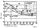
打撃フェース18のような厚みが可変の打撃フェースは、フェースのCORゾーンを広くしてゴルフクラブヘッドの許容度を高める。例えば、図16を参照すると、一定のおよび可変の厚みのフェース並びに重心z軸を中心とする慣性モーメント(Izz)の様々な組合せを有するゴルフクラブヘッドの許容度が比較されている。各ゴルフクラブヘッド構成について、打撃面上のゴルフクラブヘッドの基点x軸に沿った様々な位置で打たれたゴルフボールのボールスピードが示されている。オフセンターの打撃に対するボールスピードの低下が少ないクラブヘッドは、許容度をより大きく促進すると言われている。各ゴルフクラブヘッドは、0.820のCOR、および206gのヘッドの質量を有し、ゴルフボールとのインパクト時のスピードは109mphであった。これらの結果は、市販の有限要素解析ツールABAQUSを使用したクラブヘッドの模型作製に基づくものである。図示されているように、600kg・mm 2 のIzzおよび一定の厚さのフェースを有するゴルフクラブヘッドは、400kg・mm 2 の小さいIzzを有するが可変の厚みのフェースを有するゴルフクラブヘッドと同様の許容度特性を有する。さらに、600kg・mm 2 のIzzおよび可変厚みのフェースを有する実施形態は、800kg/mm2の大きなIzzおよび一定の厚みのフェースを有するゴルフクラブヘッドよりも許容度を大きく助長する。
A striking face with a variable thickness, such as the
このことは、厚みが可変のフェースプレートおよび600kg・mm 2 のIzzを有するクラブヘッドが、600kg・mm 2 を超えるz軸を中心とする実際の慣性モーメントを有すると言っているわけではない。それどころか、該クラブヘッドの「感触」は、z軸を中心とする大きな慣性モーメントを有するゴルフクラブヘッドに引けを取らない。したがって、厚みが可変のフェースプレートおよび600kg・mm 2 のIzzを有するクラブヘッドは、オフセンターでの打撃によるボールスピードを考慮するとき、800kg・mm 2 を超える「有効MOI」を有すると言うことができる。600kg・mm 2 未満の実際のMOI(例えば、590kg・mm 2 +10kg・mm 2 の測定許容範囲)を有するクラブヘッドは、(厚みが一定のフェースプレートの設計と比較して)有効MOIが600kg・mm 2 よりも大きいと思われるが、実際にはUSGAのMOI規則に準拠すると考えられる。 This club head having a variable faceplate and 600 kg · mm 2 Izz is not to say that with the actual moment of inertia about the z-axis of more than 600 kg · mm 2 Thickness . On the contrary, "feel" of the club head, compare favorably to the golf club head having a large moment of inertia about the z-axis. Therefore, the club head having a thickness having a variable of the face plate and 600 kg · mm 2 Izz, when considering the ball speed by hitting in the off-center, said to have an "effective MOI" of more than 800 kg · mm 2 be able to. 600 kg · mm 2 smaller than the actual MOI (e.g., 590 measurement tolerance of kg · mm 2 +10 kg · mm 2) club head having a (compared with the thickness is constant faceplate design) effective MOI is likely to be greater than 600 kg · mm 2, but in practice it is thought to conform to the MOI rules USGA.
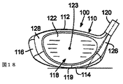
図17〜22を参照すると、別の例示的な実施形態に従って、ゴルフクラブヘッド100は、内部空洞157を画定しているクラウン112と、ソール114と、スカート116と、打撃フェース118とを有している。ボディ110は、ホーゼル120、ヒール部126、トウ部128、フロント部130、リア部132、および内部リブ182をさらに含んでいる。打撃フェース118は、打撃面の幾何学的中心123に理想的なインパクト位置を有する外方に向いているボール打撃面122を含んでいる。いくつかの実施形態では、ゴルフクラブヘッド100は、約400cm3から約490cm3の体積および約185gから約215gの全質量を有する。図17を参照すると、具体的な一実施形態では、ゴルフクラブヘッド100は約454cm3の体積および約202.8gの全質量を有している。
Referring to FIG. 17 to 22, thus to another exemplary embodiment, a
特に指定のない限り、ゴルフクラブヘッド100のボディ110の全般的な詳細および特性は、ゴルフクラブヘッド2のボディ10の同一または同様の特性を参照すれば理解することができる。
Unless otherwise specified, general details and characteristics of the
図示されている実施形態では、ゴルフクラブヘッド100のフェース118は、x軸(図21を参照)およびy軸(図22を参照)に沿って厚さプロファイルを有している。フェース118のx軸に沿った厚さプロファイルは、有効なx軸範囲のほぼ100%に沿って最小および最大厚さプロファイルによって境界が定められる。同様に、フェース118のz軸に沿った厚さプロファイルは、有効なz軸範囲のほぼ100%に沿って最小および最大厚さプロファイルによって境界が定められる。
In Tei to an embodiment shown, the
曲げ剛性プロファイルは厚さプロファイルによって変わるので、ゴルフクラブヘッド100のフェース118は、同じく有効なx軸範囲の約100%に沿って最小および最大曲げ剛性プロファイルによって境界が定められるx軸に沿った曲げ剛性プロファイルを有する。同様に、フェース118のz軸に沿った曲げ剛性プロファイルは、同じく有効なz軸範囲の約100%に沿って最小および最大曲げ剛性プロファイルによって境界が定められる。
Because the bending stiffness profile will vary with the thickness profile, the
ソール114は、ゴルフクラブヘッド100の最下点から、ゴルフクラブヘッド2のソール14よりも短い距離に亘って上方に延びている。例えば、いくつかの実施形態においては、ソール114は、ゴルフクラブヘッド100の最下点からクラウン112までの距離の約50%から60%に亘って上方に延びているが、幾つかの例においては、ドライバーに対しては約15mm、フェアウェイウッドに対しては約10mmから約12mmとすることができる。さらに、ソール114は、適切なアドレス位置にあるときに地面117に水平に延在する実質的に平らな部分119を備えている。幾つかの実施形態においては、ソール114の最も深い部分は、ゴルフクラブヘッド100の深さ(Dch)の約5%から約70%に亘って地面117に実質的に平行に延びている。
ゴルフクラブヘッド100のソール114はゴルフクラブヘッド2のソールよりも短いので、スカート116は、ゴルフクラブヘッド2のスカート16よりも背が高く即ちより長い略垂直な距離に亘って延びている。
Since the sole 114 of the
少なくとも一つの実施形態では、ゴルフクラブヘッド100は、クラブヘッドのリア部132に近接した位置のスカート116内に形成されるウェート部140を含んでいる(図19を参照)。ウェート部140は、これに言及することによって本願に組み込まれている米国特許出願第11/066,720号および第11/065,772号に記載されているような、多くのウェートまたはウェートアセンブリのいずれかを収容および保持する多くの様々な構造のうちのいずれかを有することができる。
In at least one embodiment, the
いくつかの実施形態では、ゴルフクラブヘッド100の打撃面122は、高さ(H ss )が約45mmから約65mmであり、幅(W ss )が約75mmから約105mmである。具体的な一実施形態では、打撃面122は、高さ(H ss )が約54.4mmであり、幅(W ss )が約90.6mmであり、総打撃面積が約4,098mm2 である。
In some embodiments, the
一実施形態では、ゴルフクラブヘッド100は、x軸座標が約0.0mmから約6.0mmで、y軸座標が約30mmから約50mmで、z軸座標が約0.0mmから約−6.0mmの位置に重心を有する。具体的な一つの実施形態では、重心のx軸座標は約2.0mmであり、重心のy軸座標は約37.9mmであり、重心のz軸座標は約−4.67mmである。
In one embodiment, the
いくつかの実施形態では、ゴルフクラブヘッド100は、高さ(H ch )が約48mmから約72mmであり、幅(W ch )が約100mmから約130mmであり、深さ(D ch )が約100mmから約130mmである。具体的な一実施形態では、ゴルフクラブヘッド100は、高さ(H ch )が約62.2mmであり、幅(W ch )が約119.3mmであり、深さ(D ch )が103.9mmである。
In some embodiments, the
ある種の例示的実施形態によると、ゴルフクラブヘッド100は、約490kg・mm 2 から約600kg・mm 2 の重心z軸を中心とする慣性モーメント(Izz)、および約280kg・mm 2 から約420kg・mm 2 の重心x軸を中心とする慣性モーメント(Ixx)を有している。具体的な一実施形態では、ゴルフクラブヘッド100は、約500kg・mm 2 の重心z軸を中心とする慣性モーメント(Izz)および約337kg・mm 2 の重心x軸を中心とする慣性モーメント(Ixx)を有している。
According to certain exemplary embodiments, the
図23〜27を参照すると、別の例示的な実施形態に従って、ゴルフクラブヘッド200は、ゴルフクラブヘッド100のボディ110およびゴルフクラブヘッド2のボディ10と同様の背の低いスカートを備えているボディ210を備えている。ボディ210は、内部空洞257を画定しているクラウン212、ソール214、スカート216、打撃フェース218を含んでいる。ボディ210は、ホーゼル220、ヒール部226、トウ部228、フロント部230、およびリア部232をさらに含んでいる。打撃フェース218は、打撃面の幾何学的中心223に理想的なインパクト位置を有する外方に向いているボール打撃面222を含んでいる。いくつかの実施形態では、ゴルフクラブヘッド200は、体積が約400cm3から約490cm3 であり、全質量が約185gから約215gである。図23を参照すると、具体的な一実施形態では、ゴルフクラブヘッド200は、体積が約455cm3 であり、全質量が約203.9gである。他の特定の実施形態では、ゴルフクラブヘッド200は、体積が約444cm3 であり、全質量が約205.2gの全質量である。
Referring to Figure 23 to 27 Then, in accordance with another exemplary embodiment, a
特に指定のない限り、ゴルフクラブヘッド200のボディ210の全般的な詳細および特性は、ゴルフクラブヘッド2のボディ10およびゴルフクラブヘッド100のボディ110の同一または同様の特性を参照して理解することができる。
Unless otherwise specified, general details and characteristics of
図示されている実施形態では、ゴルフクラブヘッド200の打撃フェース218は、x軸(図26を参照)およびz軸(図27を参照)に沿って厚さプロファイルを有している。フェース218のx軸に沿った厚さプロファイルは、有効なx軸範囲の約100%に沿った最小および最大厚さプロファイルによって境界が定められている。同様に、フェース218のz軸に沿った厚さプロファイルは、有効なz軸範囲の約100%に沿った最小および最大厚さプロファイルによって境界が定められている。
In Tei to an embodiment shown, the
曲げ剛性プロファイルは厚さプロファイルによって異なるので、ゴルフクラブヘッド200の打撃フェース218は、同様に有効なx軸範囲の約100%に沿った最小および最大曲げ剛性プロファイルによって境界が定められるx軸に沿った曲げ剛性プロファイルを有する。同様に、打撃フェース218のz軸に沿った曲げ剛性プロファイルは、同様に有効なz軸範囲の約100%に沿った最小および最大曲げ剛性プロファイルによって境界が定められる。
Because the bending stiffness profile differ depending on the thickness profile, the
ゴルフクラブヘッド100のソール114と同様に、ソール214はゴルフクラブヘッド200の最下点からクラウン212までの距離の約50%から約60%の距離に亘って上方に延びている。したがって、スカート216は、ゴルフクラブヘッド2のスカート16よりも高く、即ちより長いほぼ垂直な距離に亘って延びている。
Like the sole 114 of the
少なくとも一つの実施形態では、図16、18および20に示すように、ゴルフクラブヘッド200は、クラブヘッドのリア部232に近接したソール114内に形成されるウェート部240を含んでいる。ウェート部240は、多くのウェートまたはウェートアセンブリのいずれをも収容および保持する多くの様々な構造のいずれをも有することができる。例えば、図示されているように、ウェート部240は、ボディ210の壁272から内部空洞257内に向かってほぼ垂直に上方に向かって延びている。
In at least one embodiment, as shown in FIGS. 16, 18 and 20,
いくつかの実施形態では、ゴルフクラブヘッド200の打撃面222は、高さ(H ss )が約45mmから約65mmであり、幅(W ss )が75mmから約105mmである。具体的な一実施形態では、打撃面222は、高さ(H ss )が約53.5mmであり、幅(W ss )が約92.3mmであり、総打撃面積が約4,013mm2 である。別の具体的な実施形態では、打撃面222は、高さ(H ss )が約54.7mmであり、幅(W ss )が約92.3mmであり、総打撃面積が約4,115mm2 である。
In some embodiments, the
一つの実施形態では、ゴルフクラブヘッド200の重心は、x軸座標が約0.0mmから約6.0mmであり、y軸座標が約30mmから約50mmであり、z軸座標が約0.0mmから約−6.0mmである。具体的な一実施形態では、重心のx軸座標は約2.2mmであり、重心のy軸座標は約37.9mmであり、重心のz軸座標は約−4.3mmである。別の具体的な実施形態では、重心のx軸座標は約2.8mmであり、重心のy軸座標は約35.8mmであり、重心のz軸座標は約−3.4mmである。
In one embodiment, the center of gravity of the
いくつかの実施形態では、ゴルフクラブヘッド200は、高さ(H ch )が約48mmから約72mmであり、幅(W ch )が約100mmから約130mmであり、深さ(D ch )が約100mmから約130mmである。具体的な一実施形態では、ゴルフクラブヘッド200は、高さ(H ch )が約62.3mmであり、幅(W ch )が約120.0mmであり、深さ(D ch )が約111.6mmである。別の具体的な実施形態では、ゴルフクラブヘッド200は、高さ(H ch )が約62.6mmであり、幅(W ch )が約121.0mmであり、深さ(D ch )が約107.4mmの深さ(Dch)である。
In some embodiments, the
ゴルフクラブヘッド200は、いくつかの実施形態では、重心z軸を中心とする慣性モーメント(Izz)が約490kg・mm 2 から約600kg・mm 2 であり、重心x軸を中心とする慣性モーメント(Ixx)が約280kg・mm 2 から約420kg・mm 2 である。具体的な一実施形態では、クラブヘッド200は、重心z軸を中心とする慣性モーメント(Izz)が約516kg・mm 2 であり、重心x軸を中心とする慣性モーメント(Ixx)が約354kg・mm 2 である。別の具体的な実施形態では、クラブヘッド200は、重心z軸を中心とする慣性モーメント(Izz)が約496kg・mm 2 であり、重心x軸を中心とする慣性モーメント(Ixx)が約329kg・mm 2 である。
The
ここに開示したゴルフクラブヘッドの原理を応用することができる多くの可能な実施形態に鑑みると、図示されている実施形態は、ゴルフクラブヘッドの好ましい実施例に過ぎず且つゴルフクラブヘッドの範囲を限定すると考えるべきものではないことが認識されるはずである。本発明の範囲は、むしろ特許請求の範囲によって規定される。したがって、特許請求の範囲に含まれるすべてが本願発明として請求されている。 In view of the many possible embodiments to which it is possible to apply the principle of the golf club head disclosed herein, Tei to an embodiment is shown, a and range of the golf club head only preferred embodiments of the golf club head it is not to be considered as limiting it should be recognized. The scope of the invention is rather defined by the claims . Therefore, all included in the scope of the appended claims are claimed as the invention.
Claims (27)
内部空洞を画定し、該ゴルフクラブヘッドの底部に設けられているソールと、頂部に設けられているクラウンと、前記ソールと前記クラウンとの間の外周に設けられているスカートとを備えているボディであって、前部と後部とを有するボディと、
該ボディの前記前部に設けられたフェースであって、前記ゴルフクラブヘッドの基点とされる位置を規定している幾何学的中心位置を有する打撃面を画定し、前記ゴルフクラブヘッドの基点は、基点x軸と基点y軸と基点z軸との交点によって規定されており、前記基点x軸は、前記フェースに対して接線方向に延びており且つ前記ゴルフクラブヘッドの基点において前記フェースに接し且つ地面に対して略平行である直線であり、前記基点y軸は、前記基点x軸に略垂直であり且つ地面に対して略平行であり、前記基点z軸は、前記基点x軸と前記基点y軸との両方に垂直である、前記フェースと、を備え、
該ゴルフクラブヘッドは、該ゴルフクラブヘッドの重心と交差しており且つ前記基点z軸に略平行なゴルフクラブヘッド重心z軸を規定しており、該ゴルフクラブヘッドは前記ゴルフクラブヘッド重心z軸を中心とする慣性モーメントを有し、該慣性モーメントは490kg・mm 2 より大きく、
前記フェースは、前記基点y軸線方向に厚みを有し、該厚みは基点x軸線に沿って変化しており、
第1の方向と第2の方向とが、基点x軸における前記ゴルフクラブヘッドの基点を挟む正反対の正方向と負方向として規定されており、また、前記基点x軸線に沿って第1のx範囲と第2のx範囲とが規定されており、前記第1のx範囲は、第1の方向におけるゴルフクラブヘッドの基点から約10mm〜約50mmの範囲であり、前記第2のx範囲は、第2の方向におけるゴルフクラヘッドの基点から約10mmから約50mmの範囲であり、
前記厚みは、前記第1のx範囲と前記第2のx範囲との少なくとも50%に対して、tminからtmax の範囲内にあり、該t min 及びt max は、下の式によって規定されており、式中、xは、前記基点x軸に沿ったゴルフクラブヘッドの基点までの測定距離である、
Defining an interior cavity, a sole is provided at the bottom of the golf club head, a crown which is provided at the top, Ru Tei and a provided skirt on the outer periphery between the said sole crown a body, a body having a front and a rear,
A face provided on the front portion of the body, defining a striking surface having a geometric center position defining a position to be a base point of the golf club head, and the base point of the golf club head is , is defined by the intersection of a base point x and reference point y-axis and the origin z-axis, the origin x-axis, the face in contact at the base point of and the golf club head extends tangentially against the face and a linear Ru der substantially parallel against the ground, the origin y-axis, said a substantially perpendicular to the origin x axis is substantially parallel and against the ground, the origin z-axis, and the origin x-axis Ru vertical der to both the origin y-axis, and a said face,
The golf club head defines a golf club head center-of-gravity z-axis that intersects the center of gravity of the golf club head and is substantially parallel to the base point z-axis, and the golf club head includes the golf club head center-of-gravity z-axis The moment of inertia is greater than 490 kg · mm 2 ,
The face, the has a base point y-axis direction Thickness said thickness body is changing along the origin x axis,
A first direction and a second direction are defined as diametrically opposite positive and negative directions sandwiching the base point of the golf club head on the base point x-axis, and the first x along the base point x-axis line A range and a second x range, wherein the first x range is about 10 mm to about 50 mm from a golf club head base point in a first direction, and the second x range is , Ranging from about 10 mm to about 50 mm from the origin of the golf club head in the second direction;
The thickness is within a range from t min to t max with respect to at least 50% of the first x range and the second x range, and the t min and t max are defined by the following equations: Where x is the measured distance to the base point of the golf club head along the base point x-axis,
前記基点z軸線に沿って基点y軸線の方向に測定したフェースの厚みが、前記第1のz範囲及び前記第2のz範囲の少なくとも50%に対してt min からt max の間であり、前記t min 及びt max は前記第1のz範囲と前記第2のz範囲の各々に対して下の式で規定されており、式中、zは、前記基点z軸に沿った前記ゴルフクラブヘッドの基点までの測定距離である、
The face thickness measured in the direction of the base point y-axis along the base point z-axis is between t min and t max with respect to at least 50% of the first z range and the second z range ; The t min and t max are defined by the following equations for each of the first z range and the second z range, where z is the golf club along the base z axis The measurement distance to the base point of the head,
内部空洞を画定し、該ゴルフクラブヘッドの底部に設けられているソールと、頂部に設けられているクラウンと、前記ソールとクラウンとの間の外周に設けられているスカートとを備えるボディであって、前部と後部とを有するボディと、
該ボディの前記前部に設けられたフェースであって、前記ゴルフクラブヘッドの基点とされる位置を規定している幾何学的中心位置を有する打撃面を画定し、前記ゴルフクラブヘッドの基点は、基点x軸と基点y軸と基点z軸との交点によって規定されており、前記基点x軸は、前記フェースに対して接線方向に延びており且つ前記ゴルフクラブヘッドの基点において前記フェースに接し且つ地面に対して略平行である直線であり、前記基点y軸は、前記基点x軸に略垂直であり且つ地面に対して略平行であり、前記基点z軸は、前記基点x軸と前記基点y軸との両方に垂直である、前記フェースと、を備え、
該ゴルフクラブヘッドは、該ゴルフクラブヘッドの重心と交差しており且つ前記基点x軸に略平行なゴルフクラブヘッド重心x軸を規定しており、該ゴルフクラブヘッドは前記ゴルフクラブヘッド重心x軸を中心とする慣性モーメントを有し、該慣性モーメントは280kg・mm 2 より大きく、
前記フェースは、前記基点y軸線方向に厚みを有し、該厚みは基点z軸線に沿って変化しており、
前記基点x軸線に沿って第1のz範囲と第2のz範囲とが規定されており、前記第1のz範囲は、第1の方向におけるゴルフクラブヘッドの基点から約10mm〜約50mmの範囲であり、前記第2のz範囲は、第2の方向におけるゴルフクラヘッドの基点から約10mmから約50mmの範囲であり、前記第1の方向と第2の方向とは、基点z軸における前記ゴルフクラブヘッドの基点を挟む正反対の方向であり、前記第1の方向は正方向として画定されており、前記第2の方向は負方向として規定されており、
前記厚みは、前記第1のz範囲と前記第2のz範囲との少なくとも50%に対して、tminからtmax の範囲内にあり、該t min 及びt max は、下の式によって規定されており、式中、zは、前記基点z軸に沿ったゴルフクラブヘッドの基点までの測定距離である、
A body that defines an internal cavity and includes a sole provided at the bottom of the golf club head, a crown provided at the top, and a skirt provided on an outer periphery between the sole and the crown. Te, a body having a front and a rear,
A face provided on the front portion of the body, defining a striking surface having a geometric center position defining a position to be a base point of the golf club head, and the base point of the golf club head is , is defined by the intersection of a base point x and reference point y-axis and the origin z-axis, the origin x-axis, the face in contact at the base point of and the golf club head extends tangentially against the face and a linear Ru der substantially parallel against the ground, the origin y-axis, said a substantially perpendicular to the origin x axis is substantially parallel and against the ground, the origin z-axis, and the origin x-axis Ru vertical der to both the origin y-axis, and a said face,
The golf club head defines a golf club head center of gravity x-axis that intersects the center of gravity of the golf club head and is substantially parallel to the base point x-axis, and the golf club head includes the golf club head center-of-gravity x-axis And the moment of inertia is larger than 280 kg · mm 2 ,
The face, the have a Thickness in origin y-axis direction, said thickness only is changing along the origin z axis
A first z range and a second z range are defined along the base point x-axis, the first z range being about 10 mm to about 50 mm from the base point of the golf club head in the first direction. The second z-range is a range from about 10 mm to about 50 mm from the base point of the golf club head in the second direction, and the first direction and the second direction are the base axis z-axis The opposite direction across the base point of the golf club head, the first direction is defined as the positive direction, and the second direction is defined as the negative direction,
The thickness is within a range from t min to t max with respect to at least 50% of the first z range and the second z range, and the t min and t max are defined by the following equations: Where z is the measured distance to the base point of the golf club head along the base point z-axis,
前記基点x軸線に沿って基点y軸線の方向に測定したフェースの厚みが、前記第1のx範囲及び前記第2のx範囲の少なくとも50%に対してt min からt max の間であり、前記t min 及びt max は前記第1のx範囲と前記第2のx範囲の各々に対して下の式で規定されており、式中、xは、前記基点z軸に沿った前記ゴルフクラブヘッドの基点までの測定距離である、
The face thickness measured in the direction of the base point y-axis along the base point x-axis is between t min and t max with respect to at least 50% of the first x range and the second x range ; The t min and t max are defined by the following equations for each of the first x range and the second x range, where x is the golf club along the origin z-axis The measurement distance to the base point of the head,
内部空洞を画定し、該ゴルフクラブヘッドの底部に設けられているソールと、頂部に設けられているクラウンと、前記ソールとクラウンとの間の外周に設けられているスカートとを備えるボディであって、前部と後部とを有するボディと、
該ボディの前記前部に設けられたフェースであって、前記ゴルフクラブヘッドの基点とされる位置を規定している幾何学的中心位置を有する打撃面を画定し、前記ゴルフクラブヘッドの基点は、基点x軸と基点y軸と基点z軸との交点によって規定されており、前記基点x軸は、前記フェースに対して接線方向に延びており且つ前記ゴルフクラブヘッドの基点において前記フェースに接し且つ地面に対して略平行である直線であり、前記基点y軸は、前記基点x軸に略垂直であり且つ地面に対して略平行であり、前記基点z軸は、前記基点x軸と前記基点y軸との両方に垂直である、前記フェースと、を備え、
径方向r軸が、前記基点x軸、基点y軸、基点z軸によって形成されている面内に規定されており、該径方向r軸は前記基点を通っており、
該ゴルフクラブヘッドは、該ゴルフクラブヘッドの重心と交差しており且つ前記基点z軸に略平行なゴルフクラブヘッド重心z軸を規定しており、該ゴルフクラブヘッドは前記ゴルフクラブヘッド重心x軸を中心とする慣性モーメントを有し、該慣性モーメントは280kg・mm 2 より大きく、
該ゴルフクラブヘッドは、該ゴルフクラブヘッドの重心と交差しており且つ前記基点z軸に略平行なゴルフクラブヘッド重心z軸を規定しており、該ゴルフクラブヘッドは前記ゴルフクラブヘッド重心z軸を中心とする慣性モーメントを有し、該慣性モーメントは490kg・mm 2 より大きく、
前記フェースは、前記基点y軸線方向に厚みを有し、該厚みは径方向r軸に沿って変化しており、
前記径方向r軸に沿って第1のr範囲と第2のr範囲とが規定されており、前記第1のr範囲は、第1の方向におけるゴルフクラブヘッドの基点から約10mm〜約50mmの範囲であり、前記第2のr範囲は、第2の方向におけるゴルフクラヘッドの基点から約10mmから約50mmの範囲であり、前記第1の方向と第2の方向とは、径方向r軸における前記ゴルフクラブヘッドの基点を挟む正反対の方向であり、前記第1の方向は正方向として画定されており、前記第2の方向は負方向として規定されており、
前記厚みは、前記第1のr範囲と前記第2のr範囲との少なくとも50%に対して、tminからtmax の範囲内にあり、該t min 及びt max は、下の式によって規定されており、式中、rは、前記r軸に沿ったゴルフクラブヘッドの基点までの測定距離である、
A body that defines an internal cavity and includes a sole provided at the bottom of the golf club head, a crown provided at the top, and a skirt provided on an outer periphery between the sole and the crown. Te, a body having a front and a rear,
A face provided on the front portion of the body, defining a striking surface having a geometric center position defining a position to be a base point of the golf club head, and the base point of the golf club head is , is defined by the intersection of the base point x and reference point y axis and origin z axes, the origin x axis, the face in contact at the base point of and the golf club head extends tangentially against the face and a linear Ru der substantially parallel against the ground, the origin y-axis, said a substantially perpendicular to the origin x axis is substantially parallel and against the ground, the origin z-axis, and the origin x-axis Ru vertical der to both the origin y-axis, and a said face,
A radial r-axis is defined in a plane formed by the base point x-axis, base point y-axis, base point z-axis, and the radial r-axis passes through the base point;
The golf club head defines a golf club head center-of-gravity z-axis that intersects the center of gravity of the golf club head and is substantially parallel to the base point z-axis, the golf club head comprising the golf club head center-of-gravity x-axis And the moment of inertia is larger than 280 kg · mm 2 ,
The golf club head defines a golf club head center-of-gravity z-axis that intersects the center of gravity of the golf club head and is substantially parallel to the base point z-axis, and the golf club head includes the golf club head center-of-gravity z-axis The moment of inertia is greater than 490 kg · mm 2 ,
The face has a Thickness on the origin y-axis direction, said thickness only is changing along the radial direction r axis,
A first r range and a second r range are defined along the radial r-axis, and the first r range is about 10 mm to about 50 mm from the base point of the golf club head in the first direction. The second r range is a range of about 10 mm to about 50 mm from the base point of the golf club head in the second direction, and the first direction and the second direction are radial r-axis. In which the first direction is defined as a positive direction, and the second direction is defined as a negative direction.
The thickness is within a range from t min to t max with respect to at least 50% of the first r range and the second r range, and the t min and t max are defined by the following equations: Where r is the measured distance to the base point of the golf club head along the r-axis,
内部空洞を画定し、該ゴルフクラブヘッドの底部に設けられているソールと、頂部に設けられているクラウンと、前記ソールとクラウンとの間の外周に設けられているスカートとを備えるボディであって、前部と後部とを有するボディと、
該ボディの前記前部に設けられたフェースであって、前記ゴルフクラブヘッドの基点とされる位置を規定している幾何学的中心位置を有する打撃面を画定し、前記ゴルフクラブヘッドの基点は、基点x軸と基点y軸と基点z軸との交点によって規定されており、前記基点x軸は、前記フェースに対して接線方向に延びており且つ前記ゴルフクラブヘッドの基点において前記フェースに接し且つ地面に対して略平行である直線であり、前記基点y軸は、前記基点x軸に略垂直であり且つ地面に対して略平行であり、前記基点z軸は、前記基点x軸と前記基点y軸との両方に垂直である、前記フェースと、を備え、
該ゴルフクラブヘッドは、該ゴルフクラブヘッドの重心と交差しており且つ前記基点z軸に略平行なゴルフクラブヘッド重心z軸を規定しており、該ゴルフクラブヘッドは前記ゴルフクラブヘッド重心z軸を中心とする慣性モーメントを有し、該慣性モーメントは490kg・mm 2 より大きく、
前記フェースは、前記基点y軸方向において測定される曲げ剛性を有し、
前記厚みは前記基点x軸に沿って変化しており、
前記基点x軸線に沿って第1のx範囲と第2のx範囲とが規定されており、前記第1のx範囲は、第1の方向におけるゴルフクラブヘッドの基点から約10mm〜約50mmの範囲であり、前記第2のx範囲は、第2の方向におけるゴルフクラヘッドの基点から約10mmから約50mmの範囲であり、前記第1の方向と第2の方向とは、基点x軸における前記ゴルフクラブヘッドの基点を挟む正反対の方向であり、前記第1の方向は正方向として画定されており、前記第2の方向は負方向として規定されており、
前記曲げ剛性は、前記第1のx範囲と前記第2のx範囲との少なくとも50%に対して、BSminからBSmax の範囲内にあり、該BS min 及びBS max は、下の式によって規定されており、式中、xは、前記基点x軸に沿ったゴルフクラブヘッドの基点までの測定距離である、
A body that defines an internal cavity and includes a sole provided at the bottom of the golf club head, a crown provided at the top, and a skirt provided on an outer periphery between the sole and the crown. Te, a body having a front and a rear,
A face provided on the front portion of the body, defining a striking surface having a geometric center position defining a position to be a base point of the golf club head, and the base point of the golf club head is , is defined by the intersection of a base point x and reference point y-axis and the origin z-axis, the origin x-axis, the face in contact at the base point of and the golf club head extends tangentially against the face and a linear Ru der substantially parallel against the ground, the origin y-axis, said a substantially perpendicular to the origin x axis is substantially parallel and against the ground, the origin z-axis, and the origin x-axis Ru vertical der to both the origin y-axis, and a said face,
The golf club head defines a golf club head center-of-gravity z-axis that intersects the center of gravity of the golf club head and is substantially parallel to the base point z-axis, and the golf club head includes the golf club head center-of-gravity z-axis The moment of inertia is greater than 490 kg · mm 2 ,
The face has a bending stiffness measured in the base point y-axis direction ;
The thickness varies along the origin x-axis;
A first x range and a second x range are defined along the base point x-axis, and the first x range is about 10 mm to about 50 mm from the base point of the golf club head in the first direction. The second x range is a range from about 10 mm to about 50 mm from the base point of the golf club head in the second direction, and the first direction and the second direction are The opposite direction across the base point of the golf club head, the first direction is defined as the positive direction, and the second direction is defined as the negative direction,
The bending stiffness is within a range from BS min to BS max for at least 50% of the first x range and the second x range, and the BS min and BS max are expressed by the following equations: Where x is a measured distance to the base point of the golf club head along the base point x-axis,
前記基点x軸線に沿って第1のx範囲と第2のx範囲とが規定されており、前記第1のx範囲は、第1の方向におけるゴルフクラブヘッドの基点から約10mm〜約50mmの範囲であり、前記第2のx範囲は、第2の方向におけるゴルフクラヘッドの基点から約10mmから約50mmの範囲であり、前記第1の方向と第2の方向とは、基点x軸における前記ゴルフクラブヘッドの基点を挟む正反対の方向であり、前記第1の方向は正方向として画定されており、前記第2の方向は負方向として規定されており、
前記厚みは、前記第1のx範囲と前記第2のx範囲との少なくとも50%に対して、t min からt max の範囲内にあり、該t min 及びt max は、下の式によって規定されており、式中、xは、前記基点x軸に沿ったゴルフクラブヘッドの基点までの測定距離である、
A first x range and a second x range are defined along the base point x-axis, and the first x range is about 10 mm to about 50 mm from the base point of the golf club head in the first direction. The second x range is a range from about 10 mm to about 50 mm from the base point of the golf club head in the second direction, and the first direction and the second direction are The opposite direction across the base point of the golf club head, the first direction is defined as the positive direction, and the second direction is defined as the negative direction,
The thickness is within a range from t min to t max with respect to at least 50% of the first x range and the second x range , and the t min and t max are defined by the following equations: Where x is the measured distance to the base point of the golf club head along the base point x-axis,
前記基点z軸線に沿って第1のz範囲と第2のz範囲とが規定されており、前記第1のz範囲は、第1の方向におけるゴルフクラブヘッドの基点から約10mm〜約30mmの範囲であり、前記第2のz範囲は、第2の方向におけるゴルフクラヘッドの基点から約10mmから約30mmの範囲であり、前記第1の方向と第2の方向とは、基点z軸における前記ゴルフクラブヘッドの基点を挟む正反対の方向であり、前記第1の方向は正方向として画定されており、前記第2の方向は負方向として規定されており、
前記厚みは、前記第1のz範囲と前記第2のz範囲との少なくとも50%に対して、t min からt max の範囲内にあり、該t min 及びt max は、下の式によって規定されており、式中、zは、前記基点z軸に沿ったゴルフクラブヘッドの基点までの測定距離である、
A first z range and a second z range are defined along the base z axis, wherein the first z range is about 10 mm to about 30 mm from the base point of the golf club head in the first direction. The second z-range is a range from about 10 mm to about 30 mm from the base point of the golf club head in the second direction, and the first direction and the second direction are the base axis z-axis The opposite direction across the base point of the golf club head, the first direction is defined as the positive direction, and the second direction is defined as the negative direction,
The thickness is within a range from t min to t max with respect to at least 50% of the first z range and the second z range , and the t min and t max are defined by the following equations: Where z is the measured distance to the base point of the golf club head along the base point z-axis,
内部空洞を画定し、該ゴルフクラブヘッドの底部に設けられているソールと、頂部に設けられているクラウンと、前記ソールとクラウンとの間の外周に設けられているスカートとを備えるボディであって、前部と後部とを有するボディと、
該ボディの前記前部に設けられたフェースであって、前記ゴルフクラブヘッドの基点とされる位置を規定している幾何学的中心位置を有する打撃面を画定し、前記ゴルフクラブヘッドの基点は、基点x軸と基点y軸と基点z軸との交点によって規定されており、前記基点x軸は、前記フェースに対して接線方向に延びており且つ前記ゴルフクラブヘッドの基点において前記フェースに接し且つ地面に対して略平行である直線であり、前記基点y軸は、前記基点x軸に略垂直であり且つ地面に対して略平行であり、前記基点z軸は、前記基点x軸と前記基点y軸との両方に垂直である、前記フェースと、を備え、
該ゴルフクラブヘッドは、該ゴルフクラブヘッドの重心と交差しており且つ前記基点z軸に略平行なゴルフクラブヘッド重心z軸を規定しており、該ゴルフクラブヘッドは前記ゴルフクラブヘッド重心z軸を中心とする慣性モーメントを有し、該慣性モーメントは490kg・mm 2 より大きく、
前記フェースは、前記基点y軸方向において測定される曲げ剛性を有し、
前記厚みは前記基点z軸に沿って変化しており、
前記基点z軸線に沿って第1のz範囲と第2のz範囲とが規定されており、前記第1のz範囲は、第1の方向におけるゴルフクラブヘッドの基点から約10mm〜約30mmの範囲であり、前記第2のz範囲は、第2の方向におけるゴルフクラヘッドの基点から約10mmから約30mmの範囲であり、前記第1の方向と第2の方向とは、基点z軸における前記ゴルフクラブヘッドの基点を挟む正反対の方向であり、前記第1の方向は正方向として画定されており、前記第2の方向は負方向として規定されており、
前記曲げ剛性は、前記第1のz範囲と前記第2のz範囲との少なくとも50%に対して、BSminからBSmax の範囲内にあり、該BS min 及びBS max は、下の式によって規定されており、式中、zは、前記基点z軸に沿ったゴルフクラブヘッドの基点までの測定距離である、
A body that defines an internal cavity and includes a sole provided at the bottom of the golf club head, a crown provided at the top, and a skirt provided on an outer periphery between the sole and the crown. Te, a body having a front and a rear,
A face provided on the front portion of the body, defining a striking surface having a geometric center position defining a position to be a base point of the golf club head, and the base point of the golf club head is , is defined by the intersection of a base point x and reference point y-axis and the origin z-axis, the origin x-axis, the face in contact at the base point of and the golf club head extends tangentially against the face and a linear Ru der substantially parallel against the ground, the origin y-axis, said a substantially perpendicular to the origin x axis is substantially parallel and against the ground, the origin z-axis, and the origin x-axis Ru vertical der to both the origin y-axis, and a said face,
The golf club head defines a golf club head center-of-gravity z-axis that intersects the center of gravity of the golf club head and is substantially parallel to the base point z-axis, and the golf club head includes the golf club head center-of-gravity z-axis The moment of inertia is greater than 490 kg · mm 2 ,
The face has a bending stiffness measured in the base point y-axis direction ;
The thickness varies along the origin z-axis;
A first z range and a second z range are defined along the base z axis, wherein the first z range is about 10 mm to about 30 mm from the base point of the golf club head in the first direction. The second z-range is a range from about 10 mm to about 30 mm from the base point of the golf club head in the second direction, and the first direction and the second direction are the base axis z-axis The opposite direction across the base point of the golf club head, the first direction is defined as the positive direction, and the second direction is defined as the negative direction,
The bending stiffness is within a range from BS min to BS max for at least 50% of the first z range and the second z range , and the BS min and BS max are expressed by the following equations: Where z is the measured distance to the golf club head base point along the base z-axis,
前記基点x軸線に沿って第1のx範囲と第2のx範囲とが規定されており、前記第1のx範囲は、第1の方向におけるゴルフクラブヘッドの基点から約10mm〜約50mmの範囲であり、前記第2のx範囲は、第2の方向におけるゴルフクラヘッドの基点から約10mmから約50mmの範囲であり、前記第1の方向と第2の方向とは、基点x軸における前記ゴルフクラブヘッドの基点を挟む正反対の方向であり、前記第1の方向は正方向として画定されており、前記第2の方向は負方向として規定されており、
前記厚みは、前記第1のx範囲と前記第2のx範囲との少なくとも50%に対して、t min からt max の範囲内にあり、該t min 及びt max は、下の式によって規定されており、式中、xは、前記基点x軸に沿ったゴルフクラブヘッドの基点までの測定距離である、
A first x range and a second x range are defined along the base point x-axis, and the first x range is about 10 mm to about 50 mm from the base point of the golf club head in the first direction. The second x range is a range from about 10 mm to about 50 mm from the base point of the golf club head in the second direction, and the first direction and the second direction are The opposite direction across the base point of the golf club head, the first direction is defined as the positive direction, and the second direction is defined as the negative direction,
The thickness is within a range from t min to t max with respect to at least 50% of the first x range and the second x range , and the t min and t max are defined by the following equations: Where x is the measured distance to the base point of the golf club head along the base point x-axis,
前記基点z軸線に沿って第1のz範囲と第2のz範囲とが規定されており、前記第1のz範囲は、第1の方向におけるゴルフクラブヘッドの基点から約10mm〜約30mmの範囲であり、前記第2のz範囲は、第2の方向におけるゴルフクラヘッドの基点から約10mmから約30mmの範囲であり、前記第1の方向と第2の方向とは、基点z軸における前記ゴルフクラブヘッドの基点を挟む正反対の方向であり、前記第1の方向は正方向として画定されており、前記第2の方向は負方向として規定されており、
前記厚みは、前記第1のz範囲と前記第2のz範囲との少なくとも50%に対して、t min からt max の範囲内にあり、該t min 及びt max は、下の式によって規定されており、式中、zは、前記基点z軸に沿ったゴルフクラブヘッドの基点までの測定距離である、
A first z range and a second z range are defined along the base z axis, wherein the first z range is about 10 mm to about 30 mm from the base point of the golf club head in the first direction. The second z-range is a range from about 10 mm to about 30 mm from the base point of the golf club head in the second direction, and the first direction and the second direction are the base axis z-axis The opposite direction across the base point of the golf club head, the first direction is defined as the positive direction, and the second direction is defined as the negative direction,
The thickness is within a range from t min to t max with respect to at least 50% of the first z range and the second z range , and the t min and t max are defined by the following equations: Where z is the measured distance to the base point of the golf club head along the base point z-axis,
Applications Claiming Priority (2)
| Application Number | Priority Date | Filing Date | Title |
|---|---|---|---|
| US12/006,060 | 2007-12-28 | ||
| US12/006,060 US8353786B2 (en) | 2007-09-27 | 2007-12-28 | Golf club head |
Publications (3)
| Publication Number | Publication Date |
|---|---|
| JP2009160376A JP2009160376A (en) | 2009-07-23 |
| JP2009160376A5 JP2009160376A5 (en) | 2013-06-27 |
| JP5754791B2 true JP5754791B2 (en) | 2015-07-29 |
Family
ID=40963652
Family Applications (1)
| Application Number | Title | Priority Date | Filing Date |
|---|---|---|---|
| JP2008264852A Active JP5754791B2 (en) | 2007-12-28 | 2008-10-14 | Golf club head |
Country Status (1)
| Country | Link |
|---|---|
| JP (1) | JP5754791B2 (en) |
Family Cites Families (6)
| Publication number | Priority date | Publication date | Assignee | Title |
|---|---|---|---|---|
| US6354962B1 (en) * | 1999-11-01 | 2002-03-12 | Callaway Golf Company | Golf club head with a face composed of a forged material |
| US20050101404A1 (en) * | 2000-04-19 | 2005-05-12 | Long D. C. | Golf club head with localized grooves and reinforcement |
| US7186190B1 (en) * | 2002-11-08 | 2007-03-06 | Taylor Made Golf Company, Inc. | Golf club head having movable weights |
| JP2004261451A (en) * | 2003-03-03 | 2004-09-24 | Sumitomo Rubber Ind Ltd | Golf club head |
| JP4563062B2 (en) * | 2003-05-01 | 2010-10-13 | アクシュネット カンパニー | Metal wood club with improved striking face |
| JP2006149449A (en) * | 2004-11-25 | 2006-06-15 | Bridgestone Sports Co Ltd | Golf club head |
-
2008
- 2008-10-14 JP JP2008264852A patent/JP5754791B2/en active Active
Also Published As
| Publication number | Publication date |
|---|---|
| JP2009160376A (en) | 2009-07-23 |
Similar Documents
| Publication | Publication Date | Title |
|---|---|---|
| JP7200308B2 (en) | Golf club head having support for limiting deformation of faceplate | |
| US10307648B2 (en) | Golf club head or other ball striking device having stiffened face portion | |
| US9675849B2 (en) | Golf club | |
| US8353786B2 (en) | Golf club head | |
| JP6809352B2 (en) | Golf club head | |
| JP4247838B2 (en) | Composite metal wood club | |
| JP4326559B2 (en) | Golf club head | |
| JP5174129B2 (en) | Golf club head | |
| JP6219350B2 (en) | Golf club head | |
| JP2009082708A (en) | Golf club head | |
| US8038546B2 (en) | Wood-type golf club head | |
| JP4563062B2 (en) | Metal wood club with improved striking face | |
| US20050009630A1 (en) | Wood type golf club head | |
| JP2021529042A (en) | Golf club head with flexible sole | |
| JP5500895B2 (en) | Golf club head having loft-based weight and method of manufacturing golf club head | |
| JP2018102857A (en) | Golf club head | |
| JP5754791B2 (en) | Golf club head | |
| JP2010088807A (en) | Golf club | |
| JP2017153954A (en) | Golf club head with structural column | |
| JP2022108598A (en) | golf club head | |
| JP2009160376A5 (en) | ||
| JP3208316U (en) | Golf club head | |
| JP2020179030A (en) | Golf club head | |
| JP2014521484A5 (en) | ||
| JP2015033474A (en) | Golf club head |
Legal Events
| Date | Code | Title | Description |
|---|---|---|---|
| A621 | Written request for application examination |
Free format text: JAPANESE INTERMEDIATE CODE: A621 Effective date: 20101206 |
|
| A977 | Report on retrieval |
Free format text: JAPANESE INTERMEDIATE CODE: A971007 Effective date: 20121004 |
|
| A131 | Notification of reasons for refusal |
Free format text: JAPANESE INTERMEDIATE CODE: A131 Effective date: 20121203 |
|
| A601 | Written request for extension of time |
Free format text: JAPANESE INTERMEDIATE CODE: A601 Effective date: 20130304 |
|
| A602 | Written permission of extension of time |
Free format text: JAPANESE INTERMEDIATE CODE: A602 Effective date: 20130307 |
|
| A521 | Request for written amendment filed |
Free format text: JAPANESE INTERMEDIATE CODE: A523 Effective date: 20130510 |
|
| A524 | Written submission of copy of amendment under article 19 pct |
Free format text: JAPANESE INTERMEDIATE CODE: A524 Effective date: 20130510 |
|
| A131 | Notification of reasons for refusal |
Free format text: JAPANESE INTERMEDIATE CODE: A131 Effective date: 20140304 |
|
| A601 | Written request for extension of time |
Free format text: JAPANESE INTERMEDIATE CODE: A601 Effective date: 20140604 |
|
| A602 | Written permission of extension of time |
Free format text: JAPANESE INTERMEDIATE CODE: A602 Effective date: 20140609 |
|
| TRDD | Decision of grant or rejection written | ||
| A01 | Written decision to grant a patent or to grant a registration (utility model) |
Free format text: JAPANESE INTERMEDIATE CODE: A01 Effective date: 20150424 |
|
| RD04 | Notification of resignation of power of attorney |
Free format text: JAPANESE INTERMEDIATE CODE: A7424 Effective date: 20150511 |
|
| A61 | First payment of annual fees (during grant procedure) |
Free format text: JAPANESE INTERMEDIATE CODE: A61 Effective date: 20150522 |
|
| R150 | Certificate of patent or registration of utility model |
Ref document number: 5754791 Country of ref document: JP Free format text: JAPANESE INTERMEDIATE CODE: R150 |
|
| RD02 | Notification of acceptance of power of attorney |
Free format text: JAPANESE INTERMEDIATE CODE: R3D02 |
|
| R250 | Receipt of annual fees |
Free format text: JAPANESE INTERMEDIATE CODE: R250 |
|
| R250 | Receipt of annual fees |
Free format text: JAPANESE INTERMEDIATE CODE: R250 |
|
| R250 | Receipt of annual fees |
Free format text: JAPANESE INTERMEDIATE CODE: R250 |
|
| R250 | Receipt of annual fees |
Free format text: JAPANESE INTERMEDIATE CODE: R250 |
|
| SG99 | Written request for registration of restore |
Free format text: JAPANESE INTERMEDIATE CODE: R316G99 |
|
| R360 | Written notification for declining of transfer of rights |
Free format text: JAPANESE INTERMEDIATE CODE: R360 |
|
| R360 | Written notification for declining of transfer of rights |
Free format text: JAPANESE INTERMEDIATE CODE: R360 |
|
| R371 | Transfer withdrawn |
Free format text: JAPANESE INTERMEDIATE CODE: R371 |
|
| R250 | Receipt of annual fees |
Free format text: JAPANESE INTERMEDIATE CODE: R250 |
|
| R250 | Receipt of annual fees |
Free format text: JAPANESE INTERMEDIATE CODE: R250 |