JP5739269B2 - Electric tool with vibration mechanism - Google Patents
Electric tool with vibration mechanism Download PDFInfo
- Publication number
- JP5739269B2 JP5739269B2 JP2011171899A JP2011171899A JP5739269B2 JP 5739269 B2 JP5739269 B2 JP 5739269B2 JP 2011171899 A JP2011171899 A JP 2011171899A JP 2011171899 A JP2011171899 A JP 2011171899A JP 5739269 B2 JP5739269 B2 JP 5739269B2
- Authority
- JP
- Japan
- Prior art keywords
- cam
- vibration
- switching member
- electric tool
- final output
- Prior art date
- Legal status (The legal status is an assumption and is not a legal conclusion. Google has not performed a legal analysis and makes no representation as to the accuracy of the status listed.)
- Active
Links
- 230000002093 peripheral effect Effects 0.000 claims description 28
- 230000033001 locomotion Effects 0.000 claims description 22
- 210000000078 claw Anatomy 0.000 description 5
- 239000002184 metal Substances 0.000 description 2
- 230000005540 biological transmission Effects 0.000 description 1
- 238000007664 blowing Methods 0.000 description 1
- 230000008878 coupling Effects 0.000 description 1
- 238000010168 coupling process Methods 0.000 description 1
- 238000005859 coupling reaction Methods 0.000 description 1
- 230000000694 effects Effects 0.000 description 1
- 230000000149 penetrating effect Effects 0.000 description 1
Images


Classifications
-
- B—PERFORMING OPERATIONS; TRANSPORTING
- B25—HAND TOOLS; PORTABLE POWER-DRIVEN TOOLS; MANIPULATORS
- B25D—PERCUSSIVE TOOLS
- B25D16/00—Portable percussive machines with superimposed rotation, the rotational movement of the output shaft of a motor being modified to generate axial impacts on the tool bit
- B25D16/006—Mode changers; Mechanisms connected thereto
-
- B—PERFORMING OPERATIONS; TRANSPORTING
- B25—HAND TOOLS; PORTABLE POWER-DRIVEN TOOLS; MANIPULATORS
- B25B—TOOLS OR BENCH DEVICES NOT OTHERWISE PROVIDED FOR, FOR FASTENING, CONNECTING, DISENGAGING OR HOLDING
- B25B21/00—Portable power-driven screw or nut setting or loosening tools; Attachments for drilling apparatus serving the same purpose
- B25B21/02—Portable power-driven screw or nut setting or loosening tools; Attachments for drilling apparatus serving the same purpose with means for imparting impact to screwdriver blade or nut socket
-
- B—PERFORMING OPERATIONS; TRANSPORTING
- B25—HAND TOOLS; PORTABLE POWER-DRIVEN TOOLS; MANIPULATORS
- B25D—PERCUSSIVE TOOLS
- B25D11/00—Portable percussive tools with electromotor or other motor drive
- B25D11/06—Means for driving the impulse member
- B25D11/10—Means for driving the impulse member comprising a cam mechanism
- B25D11/102—Means for driving the impulse member comprising a cam mechanism the rotating axis of the cam member being coaxial with the axis of the tool
- B25D11/106—Means for driving the impulse member comprising a cam mechanism the rotating axis of the cam member being coaxial with the axis of the tool cam member and cam follower having the same shape
-
- B—PERFORMING OPERATIONS; TRANSPORTING
- B25—HAND TOOLS; PORTABLE POWER-DRIVEN TOOLS; MANIPULATORS
- B25D—PERCUSSIVE TOOLS
- B25D2216/00—Details of portable percussive machines with superimposed rotation, the rotational movement of the output shaft of a motor being modified to generate axial impacts on the tool bit
- B25D2216/0007—Details of percussion or rotation modes
- B25D2216/0023—Tools having a percussion-and-rotation mode
-
- B—PERFORMING OPERATIONS; TRANSPORTING
- B25—HAND TOOLS; PORTABLE POWER-DRIVEN TOOLS; MANIPULATORS
- B25D—PERCUSSIVE TOOLS
- B25D2216/00—Details of portable percussive machines with superimposed rotation, the rotational movement of the output shaft of a motor being modified to generate axial impacts on the tool bit
- B25D2216/0007—Details of percussion or rotation modes
- B25D2216/0038—Tools having a rotation-only mode
-
- B—PERFORMING OPERATIONS; TRANSPORTING
- B25—HAND TOOLS; PORTABLE POWER-DRIVEN TOOLS; MANIPULATORS
- B25D—PERCUSSIVE TOOLS
- B25D2216/00—Details of portable percussive machines with superimposed rotation, the rotational movement of the output shaft of a motor being modified to generate axial impacts on the tool bit
- B25D2216/0084—Mode-changing mechanisms
Landscapes
- Engineering & Computer Science (AREA)
- Mechanical Engineering (AREA)
- Drilling And Boring (AREA)
Description
本発明は、ハウジングの前方へ突出させた最終出力軸に軸方向の震動を付与する震動機構を備えたインパクトドライバ等の電動工具に関する。 The present invention relates to an electric power tool such as an impact driver provided with a vibration mechanism that imparts a vibration in the axial direction to a final output shaft that protrudes forward of a housing.
震動機構付き電動工具は、モータを収容したハウジングの前方に突出されてモータから回転伝達されるスピンドルやアンビル等の最終出力軸を備えると共に、ハウジングに、最終出力軸に軸方向の震動を付与する震動機構を備えている。例えば特許文献1には、震動機構付き電動工具として、最終出力軸であるアンビルへ一体に固着される第1カムと、その後方で互いに係合し、アンビルへ回転可能に外装される第2カムと、第2カムの外周に形成された係止歯に噛合可能な係止歯を前端に有する震動切替レバー(震動切替部材)とを含む震動機構を備えたインパクトドライバが開示されている。このインパクトドライバでは、震動切替レバーに設けた連結突起を切替ケースに設けた震動切替溝内に遊挿させて、切替ボタンによる切替ケースの回転により、震動切替レバーを、第2カムに噛合する前進位置と、第2カムから離間する後退位置とに前後移動させることで、震動の有無が切替可能となっている。 The electric tool with a vibration mechanism includes a final output shaft such as a spindle or anvil that protrudes forward of a housing housing a motor and is transmitted from the motor, and imparts axial vibration to the final output shaft. It has a vibration mechanism. For example, in Patent Document 1, as a power tool with a vibration mechanism, a first cam that is integrally fixed to an anvil that is a final output shaft, and a second cam that is engaged with each other behind the anvil and is rotatably mounted on the anvil. And an impact driver having a vibration mechanism including a vibration switching lever (vibration switching member) having a locking tooth engageable with a locking tooth formed on the outer periphery of the second cam at the front end. In this impact driver, the connection protrusion provided on the vibration switching lever is loosely inserted into the vibration switching groove provided on the switching case, and the vibration switching lever is moved forward by meshing the second cam with the rotation of the switching case by the switching button. The presence / absence of vibration can be switched by moving back and forth between the position and the retracted position separated from the second cam.
しかし、上記従来の震動機構付き電動工具においては、第2カムと震動切替部材とを軸方向へ直列に配置して、震動切替部材の前端に設けた係止歯を第2カムの外周の係止歯に噛合させているため、震動切替部材の軸方向の寸法が長くなって震動機構全体のスペースが大きくなり、ひいては工具全体のコンパクト化の障害になる。 However, in the conventional electric tool with a vibration mechanism, the second cam and the vibration switching member are arranged in series in the axial direction, and the locking teeth provided at the front end of the vibration switching member are engaged with the outer periphery of the second cam. Since it is meshed with the stop teeth, the axial dimension of the vibration switching member becomes longer, and the space of the entire vibration mechanism becomes larger, which in turn hinders the compactness of the entire tool.
そこで、本発明は、震動切替部材を含む震動機構全体を省スペースで構成でき、工具全体のコンパクト化が可能となる震動機構付き電動工具を提供することを目的としたものである。 SUMMARY OF THE INVENTION Accordingly, an object of the present invention is to provide an electric tool with an oscillating mechanism in which the entire oscillating mechanism including the oscillating switching member can be configured in a space-saving manner, and the entire tool can be made compact.
上記目的を達成するために、請求項1に記載の発明は、震動切替部材を、前進位置で第2カムに外嵌し、内周に設けた係止部を第2カムの外周に設けた被係止部に係止させて第2カムを回転規制するリング体としたことを特徴とするものである。
請求項2に記載の発明は、請求項1の構成において、前記震動切替部材を前記前進位置へ付勢する付勢手段を設ける一方、前記切替操作部材と前記震動切替部材との間に、前記震動切替部材の前面に外周側から係止して後端を前記切替操作部材に係合させ、前記切替操作部材の操作により、前記震動切替部材の前記前進位置への移動を許容する第1の位置と、前記震動切替部材を前記後退位置へ移動させる第2の位置とに前後移動する連係プレートを設けたことを特徴とするものである。
請求項3に記載の発明は、請求項1又は2の構成において、前記ハウジング内に、前記最終出力軸を軸支して前記震動機構を保持するインナーハウジングを設けて、前記連係プレートを、前記インナーハウジングの外周に凹設した外溝内で前後移動可能に保持させたことを特徴とするものである。
請求項4に記載の発明は、モータと、前記モータから回転伝達される最終出力軸と、前記最終出力軸へ一体に固着される第1カムと、前記第1カムと係合可能な第2カムと、前記第2カムを回転不能に保持する震動切替部材と、を有し、前記第1カムと、前記第2カムと、前記震動切替部材と、前記第2カムを回転不能とする位置と回転フリーとする位置とに前記震動切替部材を選択的に移動させる切替操作部材と、により、前記最終出力軸に軸方向への震動を付与可能な震動機構を形成した震動機構付き電動工具であって、前記第2カムの外周に第1の突起を設け、前記震動切替部材の内周に第2の突起を設け、前記第1の突起と前記第2の突起との係止により、前記第2カムの回転が規制されることを特徴とするものである。
請求項5に記載の発明は、請求項1又は4の構成において、前記最終出力軸は第1のバネにより付勢されており、前記震動切替部材は第2のバネにより付勢されており、前記第1のバネの径方向外側に前記第2のバネが配置されることを特徴とするものである。
請求項6に記載の発明は、請求項1乃至5の何れかの構成において、前記第1カムはベアリングにより軸支されていることを特徴とするものである。
請求項7に記載の発明は、請求項1乃至6の何れかの構成において、前記第2カムはボールにより保持されており、前記第2カムと前記ボールとは、前記最終出力軸の軸方向において重なることを特徴とするものである。
In order to achieve the above object, according to the first aspect of the present invention, the vibration switching member is externally fitted to the second cam at the forward movement position, and a locking portion provided on the inner periphery is provided on the outer periphery of the second cam. The ring body is locked to the locked portion to restrict the rotation of the second cam.
According to a second aspect of the present invention, in the configuration of the first aspect, a biasing unit that biases the vibration switching member to the forward movement position is provided, and the switching operation member and the vibration switching member are arranged between the switching operation member and the vibration switching member. The first switching member is engaged with the switching operation member by engaging the front end of the vibration switching member from the outer peripheral side, and the movement of the vibration switching member to the forward position is allowed by the operation of the switching operation member. A linkage plate that moves back and forth is provided at a position and a second position that moves the vibration switching member to the retracted position.
According to a third aspect of the present invention, in the configuration of the first or second aspect, an inner housing that supports the final output shaft and holds the vibration mechanism is provided in the housing, and the linkage plate It is characterized by being held so as to be movable back and forth in an outer groove recessed in the outer periphery of the inner housing.
According to a fourth aspect of the present invention, there is provided a motor, a final output shaft that is rotationally transmitted from the motor, a first cam that is integrally fixed to the final output shaft, and a second that is engageable with the first cam. A position where the first cam, the second cam, the vibration switching member, and the second cam are unrotatable. And a switching operation member that selectively moves the vibration switching member to a position where rotation is free, and an electric tool with a vibration mechanism that forms a vibration mechanism capable of imparting a vibration in the axial direction to the final output shaft. A first protrusion is provided on an outer periphery of the second cam, a second protrusion is provided on an inner periphery of the vibration switching member, and the first protrusion and the second protrusion are engaged with each other, The rotation of the second cam is restricted.
According to a fifth aspect of the present invention, in the configuration of the first or fourth aspect, the final output shaft is biased by a first spring, and the vibration switching member is biased by a second spring, The second spring is arranged outside in the radial direction of the first spring.
According to a sixth aspect of the present invention, in any one of the first to fifth aspects, the first cam is pivotally supported by a bearing.
According to a seventh aspect of the present invention, in the configuration of any one of the first to sixth aspects, the second cam is held by a ball, and the second cam and the ball are in an axial direction of the final output shaft. It is characterized by overlapping.
本発明によれば、震動切替部材を含む震動機構全体を省スペースで構成でき、工具全体のコンパクト化が可能となる。
請求項3の発明によれば、上記効果に加えて、連係プレートをインナーハウジングの外周から突出させずに配設でき、径方向でのコンパクト化も可能となる。
According to the present invention, the entire vibration mechanism including the vibration switching member can be configured in a space-saving manner, and the entire tool can be made compact.
According to the third aspect of the invention, in addition to the above effects, the linkage plate can be disposed without protruding from the outer periphery of the inner housing, and the radial direction can be made compact.
以下、本発明の実施の形態を図面に基づいて説明する。
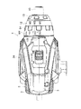
図1,2に、電動工具の一例であるインパクトドライバ1を示し、図3,4にその内部機構の一部を示す。このインパクトドライバ1は、左右の半割ハウジング3,3を組み付けて形成される本体ハウジング2を有し、本体ハウジング2内に、後方(図1の右側を前方とする。)からモータ4、遊星歯車減速機構6、スピンドル7がそれぞれ収容されている。また、本体ハウジング2の前部には、スピンドル7と共に打撃機構9を収容した筒状のインナーハウジング8が組み付けられて、スピンドル7の前方同軸上に配置された最終出力軸としてのアンビル10が、インナーハウジング8及びその前端に固定される前ハウジング12に軸支されて前方へ突出している。前ハウジング12内には、震動機構90が収容されて、本体ハウジング2を除いて遊星歯車減速機構6より前側の機構をユニット化している。13は、前ハウジング12の前端に嵌着されたゴム製リング状のバンパである。本体ハウジング2の下方には、ハンドル14が下向きに延設され、ハンドル14内には、トリガー16を備えたスイッチ15が収容されている。
Hereinafter, embodiments of the present invention will be described with reference to the drawings.
1 and 2 show an impact driver 1 which is an example of an electric tool, and FIGS. 3 and 4 show a part of its internal mechanism. The impact driver 1 has a
[遊星歯車減速機構及び変速機構]
遊星歯車減速機構6は、本体ハウジング2内に組み付けられる筒状のギヤハウジング17内に収容されている。ギヤハウジング17の後部には、モータ4の出力軸5に嵌着したピニオン18が軸支されてギヤハウジング17内に突出している。遊星歯車減速機構6は、第1インターナルギヤ19内で遊星運動する一段目の遊星歯車21,21・・を保持する第1キャリア20と、第2インターナルギヤ22内で遊星運動する二段目の遊星歯車24,24・・を保持する第2キャリア23とを備え、ピニオン18に一段目の遊星歯車21,21・・を噛合させている。また、第2キャリア23は、スピンドル7の後端へ一体に形成されてインナーハウジング8内でボールベアリング25に軸支されている。
[Planetary gear reduction mechanism and speed change mechanism]
The planetary
ここで、第1インターナルギヤ19は、内周前側に、周方向へ所定間隔で複数の内歯26,26・・を備える一方、第2インターナルギヤ22は、外周前側にリング状の係合溝27を、外周後側に、周方向へ所定間隔で突設した複数の外歯28,28・・をそれぞれ備えている。また、第2インターナルギヤ22は、第2キャリア23の後方へ一体に連結したスパーギヤ29と二段目の遊星歯車24との双方に噛合する前進位置と、第1インターナルギヤ19の内歯26に外歯28を係合させて二段目の遊星歯車24のみに噛合する後退位置との間でスライド可能に設けられている。
このスパーギヤ29は、遊星歯車24を支持する支持ピン30に貫通されて第2キャリア23と遊星歯車24との間に位置する別体のギヤで、第2キャリア23の外径は、歯先を含むスパーギヤ29の外径よりも小径となっている。36は、ギヤハウジング17内でボールベアリング25を保持する保持リングである。
Here, the first
The
第2インターナルギヤ22の外側には、ギヤハウジング17及びインナーハウジング8の内周面に沿って前後へスライド可能なスライドリング31が設けられて、スライドリング31の外側から半径方向に貫通する係合ピン32が、第2インターナルギヤ22の係合溝27と係合している。スライドリング31の上部外周には、ギヤハウジング17の上部に突出する突起33が設けられて、この突起33が、図5及び図6(A)にも示すように、本体ハウジング2に前後へスライド可能に設けたスライドボタン34に、前後のコイルバネ35,35を介して保持されている。
よって、スライドボタン34の前後へのスライド操作により、スライドリング31を介して第2インターナルギヤ22の位置を前後へ切替可能となる変速機構が形成される。すなわち、図1,2及び図8に示す第2インターナルギヤ22の前進位置では、第2インターナルギヤ22がスパーギヤ29と一体回転することで遊星歯車24の遊星運動をキャンセルした高速モード(2速)となり、図12に示す第2インターナルギヤ22の後退位置では、第2インターナルギヤ22が固定されて遊星歯車24を遊星運動させる低速モード(1速)となる。
A
Therefore, a speed change mechanism is formed in which the position of the second
[打撃機構]
打撃機構9は、アンビル10の後端に設けた一対のアーム11,11にハンマーを係脱させる構造であるが、ここでのハンマーは、スピンドル7の前端に外装され、アーム11,11に係合する一対の爪41,41を前面に突設した筒状のメインハンマー40と、そのメインハンマー40の後方でスピンドル7に同軸で遊挿されて前方が開口する有底筒状で、周壁43がメインハンマー40に後方から外装されるサブハンマー42とに分割されている。つまり、メインハンマー40とサブハンマー42の周壁43とを合わせた径が従前のハンマーの外径と等しくなっている。
まず、メインハンマー40は、その内周面に前端から後方へ向けて凹設されて後端が先細りとなる山形溝44,44と、スピンドル7の外周面で先端を前方に向けて凹設されたV字溝45,45とに跨って嵌合するボール46,46を介してスピンドル7と連結されている。
[Blow mechanism]
The
First, the
一方、メインハンマー40とサブハンマー42との間でスピンドル7には、コイルバネ47が外装されて、メインハンマー40を爪41がアーム11に係合する前進位置へ付勢する一方、サブハンマー42を後方へ付勢している。サブハンマー42と第2キャリア23との間でスピンドル7には、ワッシャー48が外装され、サブハンマー42の後面に凹設されたリング溝49には、後面から突出する複数のボール50,50・・が収容されてスラスト軸受を形成している。よって、コイルバネ47によって後方へ付勢されるサブハンマー42は、ボール50がワッシャー48に当接する後方位置へ回転可能な状態で押圧されることになる。
On the other hand, a
また、サブハンマー42の周壁43の内周面には、前端から軸方向で後方へ伸びる複数の案内溝51,51・・が、周方向へ等間隔をおいて形成されており、メインハンマー40の外周には、案内溝51よりも短い複数の長円溝52,52・・が、周方向に案内溝51と同じ間隔で形成されて、案内溝51と長円溝52とに跨って円柱状の連結ピン53,53・・が嵌合している。よって、メインハンマー40とサブハンマー42とは、連結ピン53により、軸方向への移動はそれぞれ許容された状態で、回転方向へは一体に連結される。
さらに、メインハンマー40の外周面で後端際には、周方向にリング状の嵌合溝54が凹設される一方、サブハンマー42の周壁43において、案内溝51の後端位置で案内溝51,51の間には、半径方向に貫通する複数の円形孔55,55・・が形成されて、その円形孔55にボール56がそれぞれ嵌合している。
A plurality of
Further, a ring-shaped
そして、サブハンマー42の周壁43には、切替リング57が外装されている。この切替リング57は、後側が周壁43の外周面に摺接する小径部58、前側が周壁43の外周面から半径方向へ離間する大径部59となる二段径を有し、小径部58の外周面には、リング状の凹溝60が形成されている。また、切替リング57は、インナーハウジング8の内周に設けた前側段部61と、周壁43の後端外周に設けた後側段部62との間でのみ前後へスライド可能となっている。
一方、インナーハウジング8には、図4,5に示すように、本体ハウジング2の前方に位置する切替操作部材としてのモード切替リング64を前端外周へ一体回転可能に装着した連係スリーブ63が外装されている。連係スリーブ63の外周で点対称位置には、前後方向の長円となる一対の貫通孔65,65が形成され、各貫通孔65に沿った外周面には、貫通孔65より一回り大きい四角形状の案内凹部66が形成されている。
A switching
On the other hand, as shown in FIGS. 4 and 5, the
この貫通孔65に、外側端部が案内凹部66に嵌合する正方形状のフランジ部68に形成される筒状のガイドホルダ67が貫通して、半径方向で連係スリーブ63の軸心側へ突出すると共に、案内凹部66によるフランジ部68の案内により、前後方向へ移動可能となっている。インナーハウジング8には、ガイドホルダ67が貫通し、貫通孔65の前端に対応する位置で周方向に形成される前側溝70と、貫通孔65の後端に対応する位置で周方向に形成される後側溝71と、前側溝70と後側溝71とを連通させる傾斜溝72とからなるガイド溝69が形成されている。ガイドホルダ67には、図6(B)にも示すように、インナーハウジング8の軸心側からガイドピン73が差し込まれて、ガイドピン73の頭部74を切替リング57の凹溝60に嵌合させている。
A
なお、アンビル10は、後面軸心に形成した軸受孔75に、スピンドル7の前端に突設した小径の先端部76を嵌合させて、スピンドル7の前端を同軸で軸支している。軸受孔75には、コイルバネ77によって先端部76の端面に押圧されてスラスト方向の荷重を受けるボール78が収容されている。
さらに、前ハウジング12から突出するアンビル10の前端には、ビットの装着孔79が形成されると共に、装着孔79に挿入されたビットを抜け止め装着するために、アンビル10に設けたボール81(図3)を後退位置で装着孔内へ押圧するスリーブ80等を備えたチャック機構が設けられている。
In the
Further, a
[震動機構]
震動機構90は、インナーハウジング8の前面へ同軸で結合される前筒37と、その前筒37に外装される前ハウジング12との内側に収容される。まず前ハウジング12内でアンビル10には、図4にも示すように、後面にカム面91aを形成した第1カム91が一体に固着されて、前ハウジング12内でボールベアリング92に軸支されている。第1カム91の後方でアンビル10には、前面にカム面93aを形成した第2カム93が回転可能に外装されている。この第2カム93は、インナーハウジング8の前面でリング状の受け金95に沿って収容された複数のボール94,94・・によって後面が保持されて、常態ではカム面93aを第1カム91のカム面91aと係合させている。第2カム93の外周には、半径方向へ突出する被係止部としての複数の突起96,96・・が、周方向へ等間隔をおいて形成されている。
[Vibration mechanism]
The
一方、前筒37内には、震動切替リング97が設けられている。この震動切替リング97は、第2カム93の外径よりも内径が大きいリング体で、図6(C)に示すように、外周に突設した複数の外突起98,98・・を、前筒37の内面に設けた軸方向の規制溝38,38・・に嵌合させることで、前筒37内で回転規制された状態で前後移動可能に保持されている。震動切替リング97の内周には、第2カム93に外装させた状態で第2カム93の突起96に係止する係止部としての内突起99が突設されている。すなわち、震動切替リング97が第2カム93に外装される前進位置では、第2カム93の回転を規制し、震動切替リング97が第2カム93から離間する後退位置では、第2カム93の回転を許容するものとなる。但し、前筒37内で震動切替リング97とインナーハウジング8との間には、付勢手段としてのコイルバネ100が設けられて、震動切替リング97を前進位置へ付勢している。
On the other hand, a
また、震動切替リング97には、一対の連係プレート101,101が係止している。この連係プレート101は、インナーハウジング8の前側側面へ点対称に配設される帯板状の金属板で、インナーハウジング8の側面で前後方向に形成した一対の外溝39,39に嵌合する後板部102と、その後板部102から前筒37に設けた透孔37aを貫通して内側へ折曲する中板部103と、その中板部103から前筒37の内面に沿って前方へ突出し、前端が内側へ折曲される前板部104とを有する。よって、連係プレート101は、外溝39による後板部102の案内で前後方向へ移動可能となるが、後板部102は外溝39に嵌合しているため、インナーハウジング8の外周面から突出することはない。105は、後板部102の外面に形成されて外側へ突出する係合突起である。各連係プレート101は、前板部104の前端が震動切替リング97の外側から前面に係止することで、震動切替リング97と共に前進位置へ付勢されている。
A pair of
インナーハウジング8に外装される連係スリーブ63は、周方向の一部を軸方向全長に亘って切り欠いたC字状の筒状体で、中央部に周方向の切欠き82を有し、この切欠き82に、インナーハウジング8の外周面に突設した案内突起83を嵌合させることで、前後方向への移動を規制された状態で回転可能となっている。連係スリーブ63の前側外周面には、モード切替リング64の後側内周面に設けた前後方向の連結溝85に嵌合する連結突起84が突設されて、連結溝85と連結突起84との嵌合により、モード切替リング64と連係スリーブ63とは回転方向で一体に連結されている。
The
この連結状態で、図7に示すように、連係スリーブ63の前端と、モード切替リング64の内周面で周方向に沿って形成した段部86との間に、連係プレート101の係合突起105が位置している。段部86の一部は、前方へ凹設されて周方向の両側がテーパ状に傾斜する凹部87となっており、この凹部87に係合突起105が位置すると、連係プレート101は、コイルバネ100の付勢により、震動切替リング97の前進位置への移動を許容する第1の位置へ前進する。一方、凹部87以外の段部86に係合突起105が位置すると、連係プレート101は、震動切替リング97をコイルバネ100の付勢に抗して後退位置に移動させる第2の位置へ後退することになる。
In this connected state, as shown in FIG. 7, the engagement protrusion of the
そして、連係スリーブ63の後側の外周面には、図4,5に示すように、周方向に沿った第1突条88Aと、その第1突条88Aの端部から周方向へ行くに従って後方へ直線状に傾斜する第2突条88Bとが突設されている。一方、スライドボタン34の下面で前端左側(前方から見て左側、以下左右は同様に前方から見た方向で説明する。)のコーナー部には、1速である後退位置で連係スリーブ63が回転した際に、第2突条88Bの先端と係合する受け突起89が突設されている。よって、そのまま連係スリーブ63が回転すると、第2突条88Bに沿って受け突起89が前方へ案内されることで、スライドボタン34は前進する。受け突起89が第1突条88Aの前方に乗り上がると、スライドボタン34は2速である前進位置に到達するようになっている。
As shown in FIGS. 4 and 5, on the outer peripheral surface on the rear side of the
一方、インナーハウジング8の後方下面には、一対のマイクロスイッチ106A,106Bが、プランジャ107A,107Bを前方へ向けて配設されており、連係スリーブ63の後端には、連係スリーブ63の所定の切替位置でマイクロスイッチ106A,106Bのプランジャ107A,107Bを押し込み又はその解除を行う接触子108が設けられている。このマイクロスイッチ106A,106Bは、インパクトドライバ1のハンドル14の下端に設けた図示しないコントローラに、クラッチモードのON/OFF信号を出力するもので、コントローラは、マイクロスイッチ106Bのプランジャ107Bのみの押し込みによるON信号が入力されると、モータ4に設けた図示しないトルクセンサから得られるトルク値を監視し、設定されたトルク値に達すると、モータ4へ制動をかけてアンビル10へのトルクを遮断するものとなる。
On the other hand, a pair of
[各動作モードの選択]
以上の如く構成されたインパクトドライバ1において、モード切替リング64及び連係スリーブ63の回転位置(切替位置)と各動作モードとについて説明する。
(1)インパクトモード
まず、図7に示すように、モード切替リング64を前方から見て最も右側へ回転させた第1位置では、ガイドホルダ67も右回転方向へ移動し、ガイド溝69内を移動して後側溝71に達する。よって、ガイドホルダ67は貫通孔65の後端に位置する。すると、ガイドピン73を介してガイドホルダ67に連結される切替リング57は、図8に示すように、大径部59をボール56の外側に位置させる後退位置となる。この後退位置でボール56は、周壁43の内周面に没入してメインハンマー40の嵌合溝54から離間する解除位置へ移動することができ、メインハンマー40の後退を許容するインパクトモードとなる。
[Selecting each operation mode]
In the impact driver 1 configured as described above, the rotational position (switching position) of the
(1) Impact Mode First, as shown in FIG. 7, at the first position where the
このとき、第1突条88Aがスライドボタン34の受け突起89の後方に位置してスライドボタン34を前進位置に移動させているため、スライドボタン34の後退は規制され、常に高速モードとなる。一方、連係プレート101の係合突起105は、凹部87から左側へ外れて段部86に係止しているため(図7以降のユニット部分の側面図では、係合突起105の位置をわかりやすくするためにモード切替リング64の一部を切り欠いて示している。)、連係プレート101は後退位置にあって震動切替リング97を後退させて第2カム93の回転をフリーとする。また、接触子108は、マイクロスイッチ106A,106Bの何れのプランジャ107A,107Bにも当接していない。
At this time, since the
従って、ハンドル14に設けたトリガー16を操作してモータ4を駆動させると、出力軸5の回転が遊星歯車減速機構6を介してスピンドル7に伝わり、スピンドル7を回転させる。スピンドル7は、ボール46を介してメインハンマー40を回転させ、メインハンマー40が係合するアンビル10を回転させるため、アンビル10の先端に装着したビットによってネジ締め等が可能となる。このとき連結ピン53を介して回転方向に連結されるサブハンマー42もメインハンマー40と一体に回転する。なお、アンビル10の回転に伴って第1カム91が回転しても、これと係合する第2カム93の回転はフリーであるため、第2カム93も一体回転してアンビル10に震動は発生しない。
Accordingly, when the
ネジ締めが進んでアンビル10のトルクが高まると、メインハンマー40の回転とスピンドル7の回転とにずれが生じるため、メインハンマー40は、ボール46がV字溝45に沿って転動することで、スピンドル7に対して相対的に回転しながらコイルバネ47の付勢に抗して後退する。このときサブハンマー42は、メインハンマー40の後退を許容しつつ連結ピン53を介してメインハンマー40と一体に回転する。
そして、メインハンマー40の爪41がアーム11から外れると、メインハンマー40はコイルバネ47の付勢により、ボール46がV字溝45の先端に向けて転動することで回転しながら前進する。よって、メインハンマー40の爪41が再びアーム11に係合して回転打撃力(インパクト)を発生させる。このアンビル10への係脱を繰り返すことで増し締めが行われる。
When the tightening of the screw is advanced and the torque of the
When the
このとき、サブハンマー42もメインハンマー40に追従して回転するため、両ハンマー40,42を合わせた質量でアンビル10へ係脱することになる。また、回転時には後面のボール50がワッシャー48の前面を転動することで回転抵抗が軽減されるため、メインハンマー40の前後動に伴ってコイルバネ47が伸縮してもサブハンマー42はスムーズに回転できる。さらに、メインハンマー40がインパクト発生時に前後動を繰り返しても、サブハンマー42は後方位置を維持して前後へ移動することはないため、インパクト発生時の振動は抑えられる。
At this time, since the
(2)震動ドリルモード
次に、図9に示すように、モード切替リング64を第1位置から所定角度左回転させた第2位置では、ガイドホルダ67も周方向で左回転方向へ移動し、ガイド溝69内を移動して前側溝70に達する。よって、ガイドホルダ67は貫通孔65の前端に位置する。すると、切替リング57は、図10に示すように、小径部58をボール56の外側に位置させる前進位置となる。この前進位置でボール56は、図12にも示すように小径部58に押されてメインハンマー40の嵌合溝54に嵌合する連結位置に固定されるため、メインハンマー40とサブハンマー42とを前後方向で連結してメインハンマー40の後退を規制する。
(2) Seismic drill mode Next, as shown in FIG. 9, at the second position where the
このとき、連係プレート101の係合突起105は、凹部87が同じ位相となっているため、そのまま前進して凹部87に嵌合する。よって、震動切替リング97が前進位置に移動し、第2カム93の回転を規制する震動ドリルモードとなる。
なお、連係プレート101が前進した際、震動切替リング97の内突起99と第2カム93の突起96との位相が合致して震動切替リング97が前進位置へ移動できないことがある。しかし、震動切替リング97はコイルバネ100で付勢されているため、アンビル10と共に第1カム91が回転してこれと係合する第2カム93が回転すると、突起96と内突起99との位相がずれるため、震動切替リング97が前進して第2カム93の回転を規制できる。
一方、第1突条88Aは、インパクトモードと同様にまだ受け突起89の後方に位置しているため、スライドボタン34の後退は規制され、常に高速モードとなる。また、接触子108は、マイクロスイッチ106Aのプランジャ107Aのみを押圧しているため、クラッチは作動しない。
At this time, the engaging
When the
On the other hand, since the
従って、トリガー16を操作してスピンドル7を回転させると、スピンドル7は、ボール46を介してメインハンマー40を回転させ、メインハンマー40が係合するアンビル10を回転させる。このアンビルの回転に伴って第1カム91が回転すると、回転規制される第2カム93とカム面91a,93a同士が干渉する。アンビル10は、アーム11の前後に遊びがある状態で軸支されているため、カム面91a、93a同士の干渉によってアンビル10に軸方向の震動が発生する。また、連結ピン53を介して回転方向に連結されるサブハンマー42もメインハンマー40と一体に回転する。
そして、アンビル10のトルクが高まっても、メインハンマー40はボール56によって後退が規制されるため、メインハンマー40はアンビル10に対して係脱動作を行わない。よって、インパクトは発生せず、アンビル10はスピンドル7と一体回転することになる。
Therefore, when the
And even if the torque of the
(3)ドリルモード
次に、図11に示すように、モード切替リング64を第2位置から所定角度左回転させた第3位置では、ガイドホルダ67も周方向で左回転方向へ移動するが、そのまま前側溝70内に位置するため、ガイドホルダ67が貫通孔65の前端に位置する状態は変わらない。これにより、図12にも示すように、切替リング57は前進位置にあってボール56も、小径部58に押されてメインハンマー40の嵌合溝54に嵌合する連結位置に固定される。よって、メインハンマー40とサブハンマー42とを前後方向で連結してメインハンマー40の後退を規制するドリルモードとなる。
(3) Drill mode Next, as shown in FIG. 11, in the third position where the
このとき、連係プレート101の係合突起105は、凹部87が左側へ移動することで再び段部86に係止しているため、連係プレート101は後退位置にあって震動切替リング97を後退させて第2カム93の回転をフリーとする。また、接触子108は、両方のマイクロスイッチ106A,106Bのプランジャ107A,107Bを同時に押圧しているため、クラッチは作動しない。
一方、第1突条88Aは、スライドボタン34から左側へ離れ、第2突条部88Bも端部を受け突起89よりも後方に位置させているため、図12に示すようにスライドボタン34の後退が可能となる。よって、高低何れのモードも選択できる。
At this time, the engaging
On the other hand, the
従って、トリガー16を操作してスピンドル7を回転させると、スピンドル7は、ボール46を介してメインハンマー40を回転させ、メインハンマー40が係合するアンビル10を回転させる。このとき連結ピン53を介して回転方向に連結されるサブハンマー42もメインハンマー40と一体に回転する。なお、アンビル10の回転に伴って第1カム91が回転しても、これと対向する第2カム93の回転はフリーであるため、アンビル10に震動は発生しない。
そして、アンビル10のトルクが高まっても、メインハンマー40はボール56によって後退が規制されるため、メインハンマー40はアンビル10に対して係脱動作を行わない。よって、インパクトは発生せず、アンビル10はスピンドル7と一体回転することになる。
Therefore, when the
And even if the torque of the
(4)クラッチモード
次に、図13に示すように、モード切替リング64を第3位置から所定角度左回転させた第4位置では、ガイドホルダ67も周方向で左回転方向へ移動するが、そのまま前側溝70内に位置するため、図14に示すように、ガイドホルダ67が貫通孔65の前端に位置する状態は変わらない。よって、切替リング57は前進位置にあってボール56も、小径部58に押されてメインハンマー40の嵌合溝54に嵌合する連結位置に固定される。よって、メインハンマー40とサブハンマー42とを前後方向で連結してメインハンマー40の後退を規制する。
このとき、連係プレート101の係合突起105は、第3位置と同様に段部86に係止しているため、連係プレート101は後退位置にあって震動切替リング97を後退させて第2カム93の回転をフリーとする。但し、接触子108は、マイクロスイッチ106Bのプランジャ107Bのみを押圧しているため、クラッチモードとなる。
一方、第1、第2突条88A,88Bはスライドボタン34から左側へ離れているため、スライドボタン34の前後何れへのスライド操作が可能となる。
(4) Clutch mode Next, as shown in FIG. 13, in the fourth position where the
At this time, since the engaging
On the other hand, since the first and
従って、トリガー16を操作してスピンドル7を回転させると、スピンドル7は、ボール46を介してメインハンマー40を回転させ、メインハンマー40が係合するアンビル10を回転させる。このとき連結ピン53を介して回転方向に連結されるサブハンマー42もメインハンマー40と一体に回転する。なお、アンビル10の回転に伴って第1カム91が回転しても、これと対向する第2カム93の回転はフリーであるため、アンビル10に震動は発生しない。
そして、アンビル10のトルクが高まってトルクセンサで検出されるトルク値が設定したトルク値に達すると、モータ4に制動がかけられてスピンドル7からアンビル10へのトルク伝達が遮断されることになる。
Therefore, when the
When the torque of the
なお、モード切替リング64の外周面には、図2に示すように、各動作モードに対応する表示M1(インパクトモード)、M2(震動ドリルモード)、M3(ドリルモード)、M4(クラッチモード)がそれぞれ表記されており、各表示を本体ハウジング2の上面前端に表示された矢印109に合わせることで各動作モードが選択されるようになっている。
また、低速で使用していたドリルモードやクラッチモードから震動ドリルモード又はインパクトモードに切り替える場合は、上記動作と逆に、スライドボタン34から離れていた第2突条88Bが、連係スリーブ63の右回転によって、後退位置にあるスライドボタン34の受け突起89に係合し、そのまま連係スリーブ63の回転に連れて第2突条88Bに沿って受け突起89を相対的にスライドさせながらスライドボタン34を前進位置に移動させることになる。よって、震動ドリルモード及びインパクトモードでは常に高速モードとなる。
On the outer peripheral surface of the
In addition, when switching from the drill mode or the clutch mode used at a low speed to the vibration drill mode or the impact mode, the
このように、上記形態のインパクトドライバ1によれば、震動切替部材を、前進位置で第2カム93に外嵌し、内周に設けた内突起99を第2カム93の外周に設けた突起96に係止させて第2カム93を回転規制する震動切替リング97として、震動切替リング97を前進位置へ付勢するコイルバネ100を設ける一方、モード切替リング64と震動切替リング97との間に、震動切替リング97の前面に外周側から係止して後端の係合突起105をモード切替リング64に係合させ、モード切替リング64の操作により、震動切替リング97の前進位置への移動を許容する第1の位置と、震動切替リング97を後退位置へ移動させる第2の位置とに前後移動する連係プレート101を設けたことで、震動切替リング97を含む震動機構90全体を省スペースで構成できる。よって、工具全体のコンパクト化が可能となる。
Thus, according to the impact driver 1 of the said form, the vibration switching member is externally fitted by the
特にここでは、本体ハウジング2内に、アンビル10を軸支して震動機構90を保持するインナーハウジング8を設けて、連係プレート101を、インナーハウジング8の外周に凹設した外溝39内で前後移動可能に保持させたことで、連係プレート101をインナーハウジング8の外周から突出させずに配設でき、径方向でのコンパクト化も可能となる。
In particular, here, the
なお、上記形態では、震動切替リングを第2カムに外嵌した際の回転規制を、震動切替リングの内周に設けた内突起と第2カムに設けた突起との係止によって行っているが、この内突起と突起との数の変更は勿論、その形状も、例えば横断面が山形の突起を連続状に形成して互いに噛合させる等、適宜変更可能である。
また、連係プレートも、数の変更に加え、第2カムとの位置関係によっては中板部をなくして全体を直線板状とする等の設計変更が可能である。
In the above embodiment, the rotation restriction when the vibration switching ring is externally fitted to the second cam is performed by locking the inner protrusion provided on the inner periphery of the vibration switching ring and the protrusion provided on the second cam. However, the number of the inner protrusions and the number of protrusions can be changed, and the shape thereof can be changed as appropriate, for example, by forming protrusions having a cross section in a continuous shape and meshing with each other.
In addition to the change in the number of linkage plates, design changes such as eliminating the middle plate portion and making the entire plate a straight plate shape are possible depending on the positional relationship with the second cam.
さらに、遊星歯車減速機構や打撃機構等は上記構造に限定するものではなく、例えば変速機構がないものやインパクト/ドリルの切替が行えないもの等であっても本発明は適用可能である。従って、切替操作部材も、上記形態のような回転操作されるモード切替リングに限らず、震動機構付き電動工具の形態によっては、前後方向へのスライド操作によって連係プレートを前後移動させる構造も採用できる。 Further, the planetary gear speed reduction mechanism, the striking mechanism, and the like are not limited to the above-described structures, and the present invention can be applied to, for example, a mechanism that does not have a speed change mechanism or that cannot perform impact / drill switching. Accordingly, the switching operation member is not limited to the mode switching ring that is rotated as in the above embodiment, and depending on the form of the electric tool with a vibration mechanism, a structure in which the linkage plate is moved back and forth by a sliding operation in the front-rear direction can also be adopted. .
1・・インパクトドライバ、2・・本体ハウジング、4・・モータ、5・・出力軸、6・・遊星歯車減速機構、7・・スピンドル、8・・インナーハウジング、9・・打撃機構、10・・アンビル、11・・アーム、12・・前ハウジング、17・・ギヤハウジング、19・・第1インターナルギヤ、20・・第1キャリア、21,24・・遊星歯車、22・・第2インターナルギヤ、23・・第2キャリア、31・・スライドリング、34・・スライドボタン、40・・メインハンマー、41・・爪、42・・サブハンマー、43・・周壁、47・・コイルバネ、48・・ワッシャー、49・・リング溝、50,56・・ボール、57・・切替リング、58・・小径部、59・・大径部、63・・連係スリーブ、64・・モード切替リング、65・・貫通孔、67・・ガイドホルダ、69・・ガイド溝、73・・ガイドピン、86・・段部、87・・凹部、88A・・第1突条、88B・・第2突条、89・・受け突起、90・・震動機構、91・・第1カム、93・・第2カム、97・・震動切替リング、101・・連係プレート、105・・係合突起、106A,106B・・マイクロスイッチ、108・・接触子。
1. ・ Impact driver, 2. ・ Main body housing, 4. ・ Motor, 5. ・ Output shaft, 6. ・ Planet gear reduction mechanism, 7. ・ Spindle, 8. ・ Inner housing, 9. ・ Blowing mechanism, 10. ・· Anvil, 11 · · Arm, 12 · · Front housing, 17 · · Gear housing, 19 · · First internal gear, 20 · · First carrier, 21, 24 · · Planetary gear, 22 · · Second inter Null gear, 23 ... second carrier, 31 ... slide ring, 34 ... slide button, 40 ... main hammer, 41 ... claw, 42 ... sub hammer, 43 ... peripheral wall, 47 ... coil spring, 48 ..Washers, 49..Ring grooves, 50, 56..Ball, 57..Switching ring, 58..Small diameter part, 59..Large diameter part, 63..Linking sleeve, 64..
Claims (7)
前記震動切替部材を、前記前進位置で前記第2カムに外嵌し、内周に設けた係止部を前記第2カムの外周に設けた被係止部に係止させて前記第2カムを回転規制するリング体としたことを特徴とする震動機構付き電動工具。 A final output shaft that projects forward of the housing that houses the motor and is transmitted rotationally from the motor; and a vibration mechanism that imparts a vibration in the axial direction to the final output shaft, the vibration mechanism including the final output A first cam that is integrally fixed to the shaft, a second cam that engages with each other behind the first cam and is rotatably mounted on the final output shaft, and a rear side of the second cam; An operation of a switching operation member provided in the housing, including a vibration switching member that can move back and forth between a forward position locked to the second cam and restricting rotation and a backward position spaced from the second cam; By the electric tool with a vibration mechanism for moving the vibration switching member back and forth,
The vibration switching member is externally fitted to the second cam at the forward position, and a locking portion provided on the inner periphery is locked to a locked portion provided on the outer periphery of the second cam. An electric tool with a vibration mechanism, characterized in that a ring body that restricts rotation is used.
前記切替操作部材と前記震動切替部材との間に、前記震動切替部材の前面に外周側から係止して後端を前記切替操作部材に係合させ、前記切替操作部材の操作により、前記震動切替部材の前記前進位置への移動を許容する第1の位置と、前記震動切替部材を前記後退位置へ移動させる第2の位置とに前後移動する連係プレートを設けたことを特徴とする請求項1に記載の震動機構付き電動工具。 While providing a biasing means for biasing the vibration switching member to the forward position,
Between the switching operation member and the vibration switching member, the front end of the vibration switching member is engaged from the outer peripheral side, the rear end is engaged with the switching operation member, and the vibration is operated by operating the switching operation member. claim to a first position for allowing the movement to the advanced position of the switching member, characterized in that the vibration switching member provided interconnector plate that moves back and forth and a second position moved to the retracted position The electric tool with a vibration mechanism according to 1 .
前記モータから回転伝達される最終出力軸と、
前記最終出力軸へ一体に固着される第1カムと、
前記第1カムと係合可能な第2カムと、
前記第2カムを回転不能に保持する震動切替部材と、を有し、
前記第1カムと、前記第2カムと、前記震動切替部材と、前記第2カムを回転不能とする位置と回転フリーとする位置とに前記震動切替部材を選択的に移動させる切替操作部材と、により、前記最終出力軸に軸方向への震動を付与可能な震動機構を形成した震動機構付き電動工具であって、
前記第2カムの外周に第1の突起を設け、
前記震動切替部材の内周に第2の突起を設け、
前記第1の突起と前記第2の突起との係止により、前記第2カムの回転が規制されることを特徴とする震動機構付き電動工具。 A motor,
A final output shaft that is rotationally transmitted from the motor;
A first cam integrally fixed to the final output shaft;
A second cam engageable with the first cam;
A vibration switching member that holds the second cam in a non-rotatable manner,
The first cam, the second cam, the vibration switching member, and a switching operation member that selectively moves the vibration switching member between a position where the second cam is not rotatable and a position where the second cam is rotation-free. The electric tool with a vibration mechanism that forms a vibration mechanism capable of imparting a vibration in the axial direction to the final output shaft,
Providing a first protrusion on the outer periphery of the second cam;
A second protrusion is provided on the inner periphery of the vibration switching member,
The electric tool with a vibration mechanism, wherein the rotation of the second cam is restricted by the locking of the first protrusion and the second protrusion.
前記震動切替部材は第2のバネにより付勢されており、 The vibration switching member is biased by a second spring,
前記第1のバネの径方向外側に前記第2のバネが配置されることを特徴とする請求項1又は4に記載の震動機構付き電動工具。 5. The electric tool with a vibration mechanism according to claim 1, wherein the second spring is disposed on a radially outer side of the first spring.
前記第2カムと前記ボールとは、前記最終出力軸の軸方向において重なることを特徴とする請求項1乃至6の何れかに記載の震動機構付き電動工具。 The electric tool with a vibration mechanism according to any one of claims 1 to 6, wherein the second cam and the ball overlap in the axial direction of the final output shaft.
Priority Applications (5)
| Application Number | Priority Date | Filing Date | Title |
|---|---|---|---|
| JP2011171899A JP5739269B2 (en) | 2011-08-05 | 2011-08-05 | Electric tool with vibration mechanism |
| EP12175376.8A EP2554332B1 (en) | 2011-08-05 | 2012-07-06 | Electric power tool with vibration mechanism |
| US13/566,512 US9205547B2 (en) | 2011-08-05 | 2012-08-03 | Electric power tool with vibration mechanism |
| CN201210275803.9A CN102909682B (en) | 2011-08-05 | 2012-08-03 | Electric power tool with vibration mechanism |
| RU2012133307/02A RU2012133307A (en) | 2011-08-05 | 2012-08-03 | ELECTRIC DRIVE TOOL WITH VIBRATION MECHANISM |
Applications Claiming Priority (1)
| Application Number | Priority Date | Filing Date | Title |
|---|---|---|---|
| JP2011171899A JP5739269B2 (en) | 2011-08-05 | 2011-08-05 | Electric tool with vibration mechanism |
Publications (3)
| Publication Number | Publication Date |
|---|---|
| JP2013035091A JP2013035091A (en) | 2013-02-21 |
| JP2013035091A5 JP2013035091A5 (en) | 2014-04-17 |
| JP5739269B2 true JP5739269B2 (en) | 2015-06-24 |
Family
ID=46466278
Family Applications (1)
| Application Number | Title | Priority Date | Filing Date |
|---|---|---|---|
| JP2011171899A Active JP5739269B2 (en) | 2011-08-05 | 2011-08-05 | Electric tool with vibration mechanism |
Country Status (5)
| Country | Link |
|---|---|
| US (1) | US9205547B2 (en) |
| EP (1) | EP2554332B1 (en) |
| JP (1) | JP5739269B2 (en) |
| CN (1) | CN102909682B (en) |
| RU (1) | RU2012133307A (en) |
Families Citing this family (30)
| Publication number | Priority date | Publication date | Assignee | Title |
|---|---|---|---|---|
| CA2928460C (en) * | 2012-10-30 | 2021-10-19 | Truinject Medical Corp. | System for injection training |
| JP6050110B2 (en) | 2012-12-27 | 2016-12-21 | 株式会社マキタ | Impact tools |
| WO2014156471A1 (en) * | 2013-03-26 | 2014-10-02 | 日立工機株式会社 | Electric tool |
| JP6027946B2 (en) * | 2013-06-12 | 2016-11-16 | パナソニック株式会社 | Impact wrench |
| JP6217850B2 (en) * | 2014-05-30 | 2017-10-25 | 日立工機株式会社 | Impact tool |
| JP2016055401A (en) * | 2014-09-12 | 2016-04-21 | パナソニックIpマネジメント株式会社 | Impact rotary tool |
| DE102014223036A1 (en) * | 2014-11-12 | 2016-05-12 | Robert Bosch Gmbh | TOOL AND METHOD FOR TREATING A WORKPIECE WITH A TOOL ELEMENT OF A TOOL |
| JP6543480B2 (en) * | 2015-02-20 | 2019-07-10 | 株式会社マキタ | Power tool with vibration mechanism |
| US10406662B2 (en) * | 2015-02-27 | 2019-09-10 | Black & Decker Inc. | Impact tool with control mode |
| JP6591553B2 (en) * | 2015-08-31 | 2019-10-16 | 日東工器株式会社 | Power tools |
| KR101840228B1 (en) | 2016-12-26 | 2018-03-21 | 계양전기 주식회사 | Impactor having chaanging part into drill |
| JP6832509B2 (en) * | 2017-03-27 | 2021-02-24 | パナソニックIpマネジメント株式会社 | Rotary striking tool |
| JP6957220B2 (en) * | 2017-06-14 | 2021-11-02 | 株式会社マキタ | Rotary striking tool |
| JP6976760B2 (en) * | 2017-07-14 | 2021-12-08 | 株式会社マキタ | Rotating tool |
| JP6995591B2 (en) | 2017-11-30 | 2022-01-14 | 株式会社マキタ | Impact tool |
| AU2019221782A1 (en) * | 2018-02-19 | 2020-10-08 | Milwaukee Electric Tool Corporation | Impact tool |
| JP6979605B2 (en) * | 2018-05-11 | 2021-12-15 | パナソニックIpマネジメント株式会社 | Impact rotary tool |
| TWI658907B (en) * | 2018-05-25 | 2019-05-11 | 朝程工業股份有限公司 | Double hammer impact wrench |
| EP3856463A4 (en) | 2018-09-24 | 2022-06-29 | Milwaukee Electric Tool Corporation | Power tool including input control device on top portion of housing |
| JP7154111B2 (en) * | 2018-11-08 | 2022-10-17 | 株式会社マキタ | Electric tool |
| JP2020075330A (en) * | 2018-11-08 | 2020-05-21 | 株式会社マキタ | Electric power tool |
| CN215789519U (en) * | 2018-12-21 | 2022-02-11 | 米沃奇电动工具公司 | Impact tool |
| US11673240B2 (en) * | 2019-08-06 | 2023-06-13 | Makita Corporation | Driver-drill |
| CN211805940U (en) * | 2019-09-20 | 2020-10-30 | 米沃奇电动工具公司 | Impact tool and hammer head |
| JP7458167B2 (en) * | 2019-11-08 | 2024-03-29 | 株式会社マキタ | electric screwdriver drill |
| US11964375B2 (en) | 2019-11-27 | 2024-04-23 | Black & Dekcer Inc. | Power tool with multispeed transmission |
| CN116171209A (en) | 2020-09-24 | 2023-05-26 | 创科无线普通合伙 | Multifunctional hand-held electric tool |
| CN112959253B (en) * | 2021-02-17 | 2024-02-27 | 杭州伊西威威网络科技有限公司 | Electric tool for screwing screw |
| JP2022158636A (en) * | 2021-04-02 | 2022-10-17 | 株式会社マキタ | Electric power tool and impact tool |
| JP2023090351A (en) * | 2021-12-17 | 2023-06-29 | 株式会社マキタ | impact tool |
Family Cites Families (13)
| Publication number | Priority date | Publication date | Assignee | Title |
|---|---|---|---|---|
| JPS63107510U (en) * | 1986-12-26 | 1988-07-11 | ||
| GB9309054D0 (en) * | 1993-05-01 | 1993-06-16 | Black & Decker Inc | Power tools and hammer mechanisms therefor |
| JP3656887B2 (en) * | 1999-02-15 | 2005-06-08 | 株式会社マキタ | Vibration driver drill |
| FR2868442B1 (en) * | 2004-04-01 | 2006-05-26 | Seb Sa | IRON CONTAINING AN ADDITIVE RESERVOIR |
| US7308948B2 (en) * | 2004-10-28 | 2007-12-18 | Makita Corporation | Electric power tool |
| JP4468786B2 (en) * | 2004-10-28 | 2010-05-26 | 株式会社マキタ | Impact tools |
| US7314097B2 (en) * | 2005-02-24 | 2008-01-01 | Black & Decker Inc. | Hammer drill with a mode changeover mechanism |
| CN101342693B (en) * | 2007-07-12 | 2011-08-03 | 苏州宝时得电动工具有限公司 | Power tool |
| CN101612725B (en) * | 2008-06-26 | 2013-07-31 | 苏州宝时得电动工具有限公司 | Power tool |
| JP5122400B2 (en) * | 2008-08-21 | 2013-01-16 | 株式会社マキタ | Electric tool |
| CN101786179B (en) * | 2009-01-23 | 2012-01-04 | 车王电子(宁波)有限公司 | Electric tool |
| EP2216114B1 (en) * | 2009-02-05 | 2013-08-28 | Techtronic Power Tools Technology Limited | Power tool chuck assembly with hammer mechanism |
| JP5314534B2 (en) * | 2009-08-21 | 2013-10-16 | パナソニック株式会社 | Automatic transmission for rotary electric tools |
-
2011
- 2011-08-05 JP JP2011171899A patent/JP5739269B2/en active Active
-
2012
- 2012-07-06 EP EP12175376.8A patent/EP2554332B1/en active Active
- 2012-08-03 RU RU2012133307/02A patent/RU2012133307A/en not_active Application Discontinuation
- 2012-08-03 CN CN201210275803.9A patent/CN102909682B/en active Active
- 2012-08-03 US US13/566,512 patent/US9205547B2/en active Active
Also Published As
| Publication number | Publication date |
|---|---|
| US20130032370A1 (en) | 2013-02-07 |
| RU2012133307A (en) | 2014-02-10 |
| EP2554332B1 (en) | 2018-06-20 |
| CN102909682A (en) | 2013-02-06 |
| EP2554332A2 (en) | 2013-02-06 |
| EP2554332A3 (en) | 2015-03-04 |
| CN102909682B (en) | 2014-11-26 |
| JP2013035091A (en) | 2013-02-21 |
| US9205547B2 (en) | 2015-12-08 |
Similar Documents
| Publication | Publication Date | Title |
|---|---|---|
| JP5739269B2 (en) | Electric tool with vibration mechanism | |
| JP5744669B2 (en) | Electric tool | |
| JP5744639B2 (en) | Electric tool | |
| JP5468570B2 (en) | Impact tool | |
| JP4468786B2 (en) | Impact tools | |
| JP4405900B2 (en) | Impact driver | |
| JP6995591B2 (en) | Impact tool | |
| JP5583500B2 (en) | Impact tool | |
| US7918286B2 (en) | Impact tool | |
| JP5628079B2 (en) | Vibration driver drill | |
| US8684882B2 (en) | Power tool | |
| JP4824812B2 (en) | Impact tools | |
| JP5284898B2 (en) | Impact tool | |
| WO2011046029A1 (en) | Striking device | |
| JP4391921B2 (en) | Vibration drill | |
| JP2012006101A (en) | Impact tool | |
| JP2019048382A5 (en) |
Legal Events
| Date | Code | Title | Description |
|---|---|---|---|
| A521 | Request for written amendment filed |
Free format text: JAPANESE INTERMEDIATE CODE: A523 Effective date: 20140304 |
|
| A621 | Written request for application examination |
Free format text: JAPANESE INTERMEDIATE CODE: A621 Effective date: 20140304 |
|
| A977 | Report on retrieval |
Free format text: JAPANESE INTERMEDIATE CODE: A971007 Effective date: 20150115 |
|
| A131 | Notification of reasons for refusal |
Free format text: JAPANESE INTERMEDIATE CODE: A131 Effective date: 20150120 |
|
| A521 | Request for written amendment filed |
Free format text: JAPANESE INTERMEDIATE CODE: A523 Effective date: 20150303 |
|
| TRDD | Decision of grant or rejection written | ||
| A01 | Written decision to grant a patent or to grant a registration (utility model) |
Free format text: JAPANESE INTERMEDIATE CODE: A01 Effective date: 20150331 |
|
| A61 | First payment of annual fees (during grant procedure) |
Free format text: JAPANESE INTERMEDIATE CODE: A61 Effective date: 20150423 |
|
| R150 | Certificate of patent or registration of utility model |
Ref document number: 5739269 Country of ref document: JP Free format text: JAPANESE INTERMEDIATE CODE: R150 |
|
| R250 | Receipt of annual fees |
Free format text: JAPANESE INTERMEDIATE CODE: R250 |
|
| R250 | Receipt of annual fees |
Free format text: JAPANESE INTERMEDIATE CODE: R250 |
|
| R250 | Receipt of annual fees |
Free format text: JAPANESE INTERMEDIATE CODE: R250 |
|
| R250 | Receipt of annual fees |
Free format text: JAPANESE INTERMEDIATE CODE: R250 |
|
| R250 | Receipt of annual fees |
Free format text: JAPANESE INTERMEDIATE CODE: R250 |
|
| R250 | Receipt of annual fees |
Free format text: JAPANESE INTERMEDIATE CODE: R250 |
|
| R250 | Receipt of annual fees |
Free format text: JAPANESE INTERMEDIATE CODE: R250 |