JP5736959B2 - Tire pressure monitoring device - Google Patents
Tire pressure monitoring device Download PDFInfo
- Publication number
- JP5736959B2 JP5736959B2 JP2011115005A JP2011115005A JP5736959B2 JP 5736959 B2 JP5736959 B2 JP 5736959B2 JP 2011115005 A JP2011115005 A JP 2011115005A JP 2011115005 A JP2011115005 A JP 2011115005A JP 5736959 B2 JP5736959 B2 JP 5736959B2
- Authority
- JP
- Japan
- Prior art keywords
- wheel
- rotational position
- frame
- transmitter
- time
- Prior art date
- Legal status (The legal status is an assumption and is not a legal conclusion. Google has not performed a legal analysis and makes no representation as to the accuracy of the status listed.)
- Active
Links
Images


Classifications
-
- B—PERFORMING OPERATIONS; TRANSPORTING
- B60—VEHICLES IN GENERAL
- B60C—VEHICLE TYRES; TYRE INFLATION; TYRE CHANGING; CONNECTING VALVES TO INFLATABLE ELASTIC BODIES IN GENERAL; DEVICES OR ARRANGEMENTS RELATED TO TYRES
- B60C23/00—Devices for measuring, signalling, controlling, or distributing tyre pressure or temperature, specially adapted for mounting on vehicles; Arrangement of tyre inflating devices on vehicles, e.g. of pumps or of tanks; Tyre cooling arrangements
- B60C23/02—Signalling devices actuated by tyre pressure
- B60C23/04—Signalling devices actuated by tyre pressure mounted on the wheel or tyre
- B60C23/0408—Signalling devices actuated by tyre pressure mounted on the wheel or tyre transmitting the signals by non-mechanical means from the wheel or tyre to a vehicle body mounted receiver
- B60C23/0415—Automatically identifying wheel mounted units, e.g. after replacement or exchange of wheels
- B60C23/0416—Automatically identifying wheel mounted units, e.g. after replacement or exchange of wheels allocating a corresponding wheel position on vehicle, e.g. front/left or rear/right
-
- B—PERFORMING OPERATIONS; TRANSPORTING
- B60—VEHICLES IN GENERAL
- B60C—VEHICLE TYRES; TYRE INFLATION; TYRE CHANGING; CONNECTING VALVES TO INFLATABLE ELASTIC BODIES IN GENERAL; DEVICES OR ARRANGEMENTS RELATED TO TYRES
- B60C23/00—Devices for measuring, signalling, controlling, or distributing tyre pressure or temperature, specially adapted for mounting on vehicles; Arrangement of tyre inflating devices on vehicles, e.g. of pumps or of tanks; Tyre cooling arrangements
- B60C23/02—Signalling devices actuated by tyre pressure
- B60C23/04—Signalling devices actuated by tyre pressure mounted on the wheel or tyre
- B60C23/0486—Signalling devices actuated by tyre pressure mounted on the wheel or tyre comprising additional sensors in the wheel or tyre mounted monitoring device, e.g. movement sensors, microphones or earth magnetic field sensors
- B60C23/0488—Movement sensor, e.g. for sensing angular speed, acceleration or centripetal force
-
- B—PERFORMING OPERATIONS; TRANSPORTING
- B60—VEHICLES IN GENERAL
- B60C—VEHICLE TYRES; TYRE INFLATION; TYRE CHANGING; CONNECTING VALVES TO INFLATABLE ELASTIC BODIES IN GENERAL; DEVICES OR ARRANGEMENTS RELATED TO TYRES
- B60C23/00—Devices for measuring, signalling, controlling, or distributing tyre pressure or temperature, specially adapted for mounting on vehicles; Arrangement of tyre inflating devices on vehicles, e.g. of pumps or of tanks; Tyre cooling arrangements
- B60C23/02—Signalling devices actuated by tyre pressure
- B60C23/04—Signalling devices actuated by tyre pressure mounted on the wheel or tyre
- B60C23/0486—Signalling devices actuated by tyre pressure mounted on the wheel or tyre comprising additional sensors in the wheel or tyre mounted monitoring device, e.g. movement sensors, microphones or earth magnetic field sensors
- B60C23/0489—Signalling devices actuated by tyre pressure mounted on the wheel or tyre comprising additional sensors in the wheel or tyre mounted monitoring device, e.g. movement sensors, microphones or earth magnetic field sensors for detecting the actual angular position of the monitoring device while the wheel is turning
Landscapes
- Engineering & Computer Science (AREA)
- Mechanical Engineering (AREA)
- Measuring Fluid Pressure (AREA)
Description
本発明は、車両の各タイヤの空気圧を監視するタイヤ空気圧モニター装置に関する。 The present invention relates to a tire air pressure monitoring device that monitors the air pressure of each tire of a vehicle.
従来、各車輪のタイヤにそれぞれ取り付けられたタイヤ空気圧センサの送信機がどの車輪位置(車両に対するタイヤの取付け位置)にあるかを判定するタイヤ空気圧モニター装置が知られている(例えば特許文献1)。 2. Description of the Related Art Conventionally, there is known a tire pressure monitoring device that determines which wheel position (attachment position of a tire to a vehicle) a tire pressure sensor transmitter attached to each wheel tire is located (for example, Patent Document 1). .
走行時には、送信機は車輪と共に回転すると共に、各車輪間で回転数に差が生じうる。よって、送信機の車輪位置を精度良く判定するためには、各車輪において送信機が送信を行う回転位置(回転角度)を車体側で正確に検出することが好ましい。しかしながら、送信機の回転位置には、車体側が送信機から受信する電波強度が低くなるポイントないし領域(Null点)が存在する。よって、送信機が送信を行う回転位置がNull点の近傍に位置すると、その受信確率が低下して、送信機の送信時における回転位置を車体側で正確に検出することができず、送信機の車輪位置の判定精度が低下するおそれがある。
本発明の目的は、送信機の車輪位置をより精度良く判定できるタイヤ空気圧モニター装置を提供することにある。
When traveling, the transmitter rotates with the wheels and there may be a difference in the number of rotations between the wheels. Therefore, in order to accurately determine the wheel position of the transmitter, it is preferable to accurately detect the rotation position (rotation angle) at which the transmitter transmits in each wheel on the vehicle body side. However, at the rotational position of the transmitter, there is a point or a region (null point) where the intensity of radio waves received from the transmitter on the vehicle body side becomes low. Therefore, if the rotational position at which the transmitter transmits is located near the null point, the reception probability decreases, and the rotational position at the time of transmission of the transmitter cannot be accurately detected on the vehicle body side. There is a risk that the determination accuracy of the wheel position of the vehicle will decrease.
An object of the present invention is to provide a tire pressure monitoring device that can determine the wheel position of a transmitter with higher accuracy.
上述の目的を達成するため、本発明では、送信機は、送信する信号を重複して複数のフレームとし、各フレームを互いに間隔をおいて送信し、各フレームに該フレームの送信時における送信機の回転位置情報を含め、車体側では、複数のフレームのうち受信されたものの受信情報に基づいて、送信機の送信時における回転位置を推定する。 In order to achieve the above object, in the present invention, a transmitter overlaps a signal to be transmitted into a plurality of frames, transmits each frame at intervals, and transmits each frame to the transmitter at the time of transmission of the frame. The rotational position information at the time of transmission of the transmitter is estimated on the vehicle body side including the rotational position information on the basis of the reception information of the received frames.
よって、受信確率を向上して、各車輪における送信機の送信時における回転位置を車体側でより正確に検出することが可能となるため、送信機の車輪位置をより精度良く判定することができる。 Therefore, it is possible to improve the reception probability and more accurately detect the rotational position at the time of transmission of the transmitter in each wheel on the vehicle body side, so that the wheel position of the transmitter can be determined with higher accuracy. .
以下、本発明を実施するため形態を、図面に基づく実施例を用いて説明する。
〔実施例1〕
図1は、実施例1のタイヤ空気圧モニター装置の構成図である。図において、各符号の末尾のFLは左前輪、FRは右前輪、RLは左後輪、RRは右後輪に対応することを示す。以下の説明では、個別に説明する必要がない場合にはFL,FR,RL,RRの記載を省略する。
実施例1のタイヤ空気圧モニター装置は、TPMS(Tire Pressure Monitoring System)センサ2と、受信機3と、TPMSコントロールユニット(TPMSCU)4と、ディスプレイ5と、車輪速センサ(回転位置検出手段)8とを備える。TPMSセンサ2は各車輪1に装着され、受信機3、TPMSCU4、ディスプレイ5および車輪速センサ8は車体側に設けられている。
DESCRIPTION OF EMBODIMENTS Hereinafter, embodiments for carrying out the present invention will be described using embodiments based on the drawings.
[Example 1]
FIG. 1 is a configuration diagram of a tire pressure monitoring apparatus according to the first embodiment. In the figure, FL at the end of each symbol indicates a left front wheel, FR indicates a right front wheel, RL indicates a left rear wheel, and RR indicates a right rear wheel. In the following description, the description of FL, FR, RL, and RR is omitted when there is no need to explain them individually.
The tire pressure monitoring device of the first embodiment includes a TPMS (Tire Pressure Monitoring System)
TPMSセンサ2は、タイヤの空気バルブ(不図示)位置に取り付けられている。図2は、TPMSセンサ2の構成図である。TPMSセンサ2は、圧力センサ(タイヤ空気圧検出手段)2aと、加速度センサ(Gセンサ)2bと、センサコントロールユニット(センサCU)2cと、送信機2dと、ボタン電池2eとを備える。
圧力センサ2aは、タイヤの空気圧[kPa]を検出する。
Gセンサ2bは、タイヤに作用する遠心方向加速度[G]を検出する。
センサCU2cは、ボタン電池2eからの電力により動作し、圧力センサ2aにより検出されたタイヤの空気圧情報とセンサID(識別情報)とを含むTPMSデータを無線信号により送信機2dから送信する。実施例1では、センサIDを1〜4とする。
The
The
The
The sensor CU2c operates by the electric power from the
センサCU2cは、Gセンサ2bにより検出された遠心方向加速度とあらかじめ設定された走行判定しきい値とを比較し、遠心方向加速度が走行判定しきい値未満の場合は車両停止と判定してTPMSデータの送信を停止する。一方、遠心方向加速度が走行判定しきい値以上の場合は車両が走行していると判定し、所定のタイミングでTPMSデータの送信を行う。
受信機3は、車両に1つ設けられており、各TPMSセンサ2から出力された無線信号を受信してデコードし、TPMSCU4へ出力する。
The sensor CU2c compares the centrifugal acceleration detected by the
One
TPMSCU4は、各TPMSデータを読み込み、TPMSデータのセンサIDから、不揮発性のメモリ4d(図3参照)に記憶した各センサIDと各車輪位置(FL,FR,RL,RR)との対応関係を参照して当該TPMSデータがどの車輪位置に対応するものであるのかを判定し、当該TPMSデータに含まれるタイヤの空気圧を対応する車輪位置の空気圧としてディスプレイ5に表示する。また、タイヤの空気圧が下限値を下回った場合には、表示色変更、点滅表示や警告音などによりドライバに空気圧の低下を知らせる。
TPMSCU4 reads each TPMS data, and from the sensor ID of the TPMS data, the correspondence between each sensor ID stored in the
各車輪速センサ8は、車輪1の1回転について所定数z(例えば、z=48)の車輪速パルスを発生するパルス発生器であり、車輪1と同期して回転する歯車状のロータと、車体側であってロータの外周に対向配置されたステータ(永久磁石およびコイル)とから構成される。ロータが回転すると、ロータの凹凸面がステータの周りに形成された磁界を横切ることによりその磁束密度が変化してコイルに起電力が生じ、この電圧変化を車輪速パルス信号としてABSCU6に出力する。
ABSCU6は、各車輪速センサ8からの車輪速パルスに基づいて、各車輪1の車輪速を検出し、ある車輪がロック傾向にある場合、図外のABSアクチュエータを作動させて当該車輪のホイルシリンダ圧を増減または保持してロック傾向を抑制するアンチスキッドブレーキ制御を実施する。ABSCU6は、所定の時間間隔ΔT0(例えば、20msecの周期)で車輪速パルスのカウント値をCAN通信線7に出力する。
Each wheel speed sensor 8 is a pulse generator that generates a predetermined number z (for example, z = 48) of wheel speed pulses for one rotation of the
ABSCU 6 detects the wheel speed of each
上記のように、TPMSCU4は、メモリ4dに記憶した各センサIDと各車輪位置との対応関係に基づいて、受信したTPMSデータがどの車輪のデータであるのかを判定する。よって、車両停止中にタイヤローテーションが行われた場合、メモリ4dに記憶された各センサIDと各車輪位置との対応関係が実際の対応関係と合致せず、TPMSデータがどの車輪のデータであるのかがわからなくなる。ここで、「タイヤローテーション」とは、タイヤのトレッド摩耗を均一にし、寿命(トレッドライフ)を延ばすため、タイヤの装着位置を複数の車輪間で変えることをいう。例えば、乗用車では、一般的に、左右のタイヤ位置をクロスして前後輪を入れ替える。
そこで、実施例1では、タイヤローテーション後の各センサIDと各車輪位置との対応関係をメモリ4dへの記憶更新により登録するために、タイヤローテーションが行われた可能性の有無を判断する。可能性がある場合、各TPMSセンサ2側ではTPMSデータの送信周期を変更し、TPMSCU4側ではTPMSデータの送信周期と各車輪速パルスとに基づいて各TPMSセンサ2がどの車輪のものであるのかを判定する。
As described above, the TPMSCU 4 determines which wheel data the received TPMS data is based on the correspondence between each sensor ID stored in the
Therefore, in Example 1, in order to register the correspondence between each sensor ID and each wheel position after tire rotation by storing and updating in the
[定位置送信モード]
TPMSセンサ2のセンサCU2cは、走行開始直前の車両停止判定時間が所定時間T1(例えば、15分)以上である場合、タイヤローテーションが行われた可能性があると判断する。
センサCU2cは、走行開始直前の車両停止判定時間が所定時間T1未満である場合、一定間隔(例えば、1分間隔)でTPMSデータを送信する「通常モード」を実施する。一方、センサCU2cは、車両停止判定時間が所定時間T1以上である場合、通常モードの送信間隔よりも短い間隔(例えば、約16秒間隔)であって、一定の回転位置でTPMSデータを送信する「定位置送信モード」を実施する。
[Position transmission mode]
The sensor CU2c of the
When the vehicle stop determination time immediately before the start of traveling is less than the predetermined time T1, the sensor CU2c performs the “normal mode” in which TPMS data is transmitted at regular intervals (eg, 1 minute intervals). On the other hand, when the vehicle stop determination time is equal to or longer than the predetermined time T1, the sensor CU2c transmits TPMS data at a constant rotational position that is shorter than the transmission interval in the normal mode (for example, approximately 16 seconds). Implement "Position transmission mode".
センサCU2cは、定位置送信モードを、TPMSデータの送信回数が所定回数N1(例えば、40回)に達するまで実施する。センサCU2cは、送信回数が所定回数N1に達した場合、通常モードへ移行する。TPMSデータの送信回数が所定回数N1に達する前に車両停止と判定した場合、車両停止判定時間が所定時間T1(15分)未満であるときは送信回数が所定回数N1に達するまで車両停止前の定位置送信モードを継続し、車両停止判定時間が所定時間T1以上であるときは車両停止前の定位置送信モードの継続をキャンセルして新たに定位置送信モードを開始する。 The sensor CU2c executes the fixed position transmission mode until the number of transmissions of TPMS data reaches a predetermined number N1 (for example, 40 times). The sensor CU2c shifts to the normal mode when the number of transmissions reaches the predetermined number N1. If it is determined that the vehicle has stopped before the number of transmissions of TPMS data reaches the predetermined number N1, if the vehicle stop determination time is less than the predetermined time T1 (15 minutes), the number of transmissions before the vehicle stops until the predetermined number N1 is reached. The fixed position transmission mode is continued, and when the vehicle stop determination time is equal to or longer than the predetermined time T1, the continuation of the fixed position transmission mode before the vehicle is stopped is canceled and the fixed position transmission mode is newly started.
センサCU2cは、定位置送信モード中、Gセンサ2bにより検出された遠心方向加速度の重力加速度依存成分に基づいて、定位置送信モードにおけるTPMSデータの送信タイミングを決定する。TPMSセンサ2に作用する遠心方向加速度は、車輪1の加減速によって変化するが、その重力加速度依存成分は常に一定であり、最上点で+1[G]、最下点で-1[G]、最上点および最下点に対し90度の位置で0[G]となる波形を示す。すなわち、遠心方向加速度の重力加速度成分の大きさ、方向をモニターすることで、TPMSセンサ2の回転位置を把握できる。よって、例えば、重力加速度依存成分のピーク(+1[G])でTPMSデータを出力することで、最上点でTPMSデータを出力する。
The sensor CU2c determines the transmission timing of the TPMS data in the fixed position transmission mode based on the gravitational acceleration dependent component of the centrifugal acceleration detected by the
定位置送信モードでは、センサCU2cは、図3に示すように、TPMSデータの1回の送信につき、タイヤの空気圧情報とセンサIDとを含む同一内容のフレームを複数、具体的には3つ送信する。第1フレームを最上点で送信し、間隔をおいて他のフレームを送信する。具体的には、第2フレームを第1フレームの送信から第1の時間間隔ΔT1(例えば、100msec)後に送信し、第3フレームを第2フレームの送信から第2の時間間隔ΔT2(例えば、140msec)後に送信する。各フレームには、そのフレームが何番目のフレームであるか分るように、識別情報としてフレーム番号(1〜3)を付す。 In the fixed position transmission mode, as shown in FIG. 3, the sensor CU2c transmits a plurality of frames, specifically, three frames having the same content including tire pressure information and sensor ID for each transmission of TPMS data. To do. The first frame is transmitted at the top point, and other frames are transmitted at intervals. Specifically, the second frame is transmitted after a first time interval ΔT1 (for example, 100 msec) from the transmission of the first frame, and the third frame is transmitted from the transmission of the second frame to a second time interval ΔT2 (for example, 140 msec). ) Send later. Each frame is given a frame number (1 to 3) as identification information so that it can be seen what number the frame is.
[オートラーニングモード]
TPMSCU4は、イグニッションスイッチのOFFからONまでの経過時間が所定時間T2(例えば、15分)以上である場合、タイヤローテーションが行われた可能性があると判断する。
TPMSCU4は、イグニッションスイッチのOFFからONまでの経過時間が所定時間T2未満である場合、各TPMSセンサ2から送信されたTPMSデータの空気圧情報に基づいて各車輪1のタイヤの空気圧を監視する「モニターモード」を実施する。一方、イグニッションスイッチのOFFからONまでの経過時間が所定時間T2以上である場合、各TPMSセンサ2の車輪位置を判定する「オートラーニングモード」を実施する。オートラーニングモードは、すべてのTPMSセンサ2の車輪位置を判定するまで、または、当該モードの開始から所定の累積走行時間(例えば、8分)が経過するまで実施する。すべてのTPMSセンサ2の車輪位置を判定した場合、または所定の累積走行時間が経過した場合、モニターモードへ移行する。
[Auto learning mode]
The
TPMSCU4 monitors the tire air pressure of each
なお、オートラーニングモード中であっても、TPMSデータに含まれる空気圧情報からタイヤの空気圧の監視は可能である。よって、オートラーニングモード中は現在メモリ4dに記憶されている各センサIDと各車輪位置との対応関係に基づいて空気圧の表示、空気圧低下の警告を行う。
TPMSCU4は、オートラーニングモード中、ABSコントロールユニット(ABSCU)6からCAN通信線7を介して車輪速パルスのカウント値を入力し、以下に示すような車輪位置判定制御を実施する。
Even during the auto-learning mode, the tire pressure can be monitored from the air pressure information included in the TPMS data. Therefore, during the auto-learning mode, air pressure is displayed and air pressure drop warning is performed based on the correspondence between each sensor ID and each wheel position currently stored in the
The
[車輪位置判定制御]
図4は、車輪位置判定制御を実施するためのTPMSCU4の制御ブロック図である。TPMSCU4は、回転位置演算部4aと、分散演算部4bと、車輪位置判定部4cと、メモリ4dとを備える。
回転位置演算部4aは、受信機3から出力されたデコード後のTPMSデータと、ABSCU6からCAN通信線7に出力された各車輪速パルスのカウント値を入力し、各TPMSセンサ2(送信機2d)の送信時(回転位置が最上点となったとき)における各車輪1の回転位置(ロータの歯数z)を演算する。ここで、「ロータの歯数」とは、車輪速センサ8がロータのどの歯をカウントしているかを示すものであり、車輪速パルスのカウント値をタイヤ1回転分のカウント値(1回転分の歯数z=48)で除算した余りで求めることができる。実施例1では、オートラーニングモードを開始してから最初に入力された車輪速パルスのカウント値を1回転分の歯数(=48)で除算した余りを基準歯数とし、以後は基準歯数からの車輪速パルスのカウント数(現在のカウント値-基準歯数)に基づいて歯数を決定する。
[Wheel position determination control]
FIG. 4 is a control block diagram of the
The rotational
図5は、回転位置演算部4aにて実行される、各車輪1におけるTPMSセンサ2(送信機2d)の回転位置の算出方法を示す図である。
回転位置演算部4aは、TPMSデータ(第1〜第3フレーム)を受信する都度、その受信時刻とデータ内容を記憶する。また、CAN通信線7を介して車輪速パルスのカウント値の入力を受ける都度、その入力時刻とカウント値を記憶する。
FIG. 5 is a diagram illustrating a calculation method of the rotational position of the TPMS sensor 2 (
Each time the rotational
まず、第1フレームを受信した場合の算出方法を説明する。図5において、TPMSデータ(第1フレーム)の受信を開始する直前に車輪速パルスのカウント値(前回値)が入力された時刻をt1、TPMSセンサ2の回転位置が最上点となってTPMSデータ(第1フレーム)の送信が指令された時刻をt2、TPMSセンサ2が実際にTPMSデータ(第1フレーム)の送信を開始した時刻(TPMSCU4が第1フレームの受信を開始した時刻と同じとみなせる。)をt3、TPMSCU4がTPMSデータ(第1フレーム)の受信を完了した時刻(TPMSセンサ2が第1フレームの送信を終了した時刻と同じとみなせる。)をt4、TPMSデータ(第1フレーム)の受信を完了した直後に車輪速パルスのカウント値(今回値)が入力された時刻をt5とする。回転位置演算部4aは、時刻t1,t4,t5を記憶すると共に、時刻t4からTPMSデータ(第1フレーム)の送信時間Δt1(データ長に応じて送信機2dに固有の値として予め規定されており、例えば、約10msec)を減算して時刻t3を算出する(t4 -Δt1 = t3)。また、時刻t3から送信時のタイムラグΔt0(予め実験等により求めることができる。)を減算して時刻t2を算出する(t3 -Δt0 = t2)。なお、時刻t4から時刻t2を算出するのではなく、時刻t3を直接検出・記憶して、この時刻t3から時刻t2を算出することとしてもよい。
よって、時刻t1でのロータの歯数をzt1、時刻t2での歯数をzt2、t5での歯数をzt5とすると、
(t2 - t1) / (t5 - t1) = (zt2 - zt1) / (zt5 - zt1)
が成立する。
zt2 - zt1 = (zt5 - zt1) × (t2 - t1) / (t5 - t1)
であるから、TPMSセンサ2の回転位置が最上点となって送信が指令された時刻t2の歯数zt2は、
zt2 = zt1 + (zt5 - zt1) × (t2 - t1) / (t5 - t1) ・・・(1)
により算出することができる。上記式(1)における{(zt5 - zt1) / (t5 - t1)}は、単位時間当たりの歯数に相当する。
なお、車輪速パルスのカウント値がTPMSデータの受信中に入力されるような場合(図6参照)もある。この場合も、TPMSデータを受信する直前に車輪速パルスのカウント値が入力された時刻t1とTPMSデータを受信した直後に車輪速パルスのカウント値が入力された時刻t5とに基づき、上記式(1)を用いて時刻t2の歯数zt2を算出することができる。
以上のように、回転位置演算部4aは、各車輪1について、送信機2dからの無線信号(送信データ)の受信情報(受信完了時刻t4)と、CAN通信線7を介して入力される車輪1の回転位置情報(入力時刻t1,t5、歯数zt1,zt5)とに基づいて、送信機2dの送信時(送信指令時刻t2)における回転位置(歯数zt2)を推定する。
First, a calculation method when the first frame is received will be described. In FIG. 5, the time when the wheel speed pulse count value (previous value) was input immediately before the start of reception of TPMS data (first frame) is t1, and the rotational position of the
Therefore, if the number of teeth of the rotor at time t1 is z t1 , the number of teeth at time t2 is z t2 , and the number of teeth at t5 is z t5 ,
(t2-t1) / (t5-t1) = (z t2 -z t1 ) / (z t5 -z t1 )
Is established.
z t2 -z t1 = (z t5 -z t1 ) × (t2-t1) / (t5-t1)
Therefore, the number of teeth z t2 at time t2 when transmission is commanded with the rotational position of the
z t2 = z t1 + (z t5 -z t1 ) × (t2-t1) / (t5-t1) (1)
Can be calculated. {(Z t5 -z t1 ) / (t5 -t1)} in the above formula (1) corresponds to the number of teeth per unit time.
In some cases, the count value of the wheel speed pulse is input during reception of TPMS data (see FIG. 6). Also in this case, based on the time t1 when the count value of the wheel speed pulse was input immediately before receiving the TPMS data and the time t5 when the count value of the wheel speed pulse was input immediately after receiving the TPMS data, the above formula ( The number of teeth z t2 at time t2 can be calculated using 1).
As described above, for each
次に、第1フレームを受信せず、第2フレームを受信した場合の算出方法を説明する。第2フレームは第1フレームの送信から100msec後、すなわち車輪速パルスのカウント値が入力される周期ΔT0(20msec)の5回分の時間間隔ΔT1後に送信される。よって、上記式(1)において5周期(ΔT0×5)前のzt1, zt5を用いれば、TPMSセンサ2の回転位置が最上点となったとき(第1フレームの送信が指令された時刻t2)の車輪1の回転位置zt2を算出することができる。具体的には、第2フレームの受信を開始する直前に車輪速パルスのカウント値(前回値)が入力された時刻をt1'、第1フレームの送信指令時刻t2から100msec 経過して第2フレームの送信が指令された時刻をt2'、TPMSセンサ2が実際に第2フレームの送信を開始した時刻をt3'、TPMSCU4が第2フレームの受信を完了した時刻をt4'、第2フレームの受信が完了した直後に車輪速パルスのカウント値(今回値)が入力された時刻をt5'とする。回転位置演算部4aは、時刻t1',t4',t5'を記憶すると共に、フレーム番号から第2フレームを受信したと判定した場合、
t1= t1' - 100msec
t4= t4' - 100msec
t5= t5' - 100msec
により、仮に第1フレームが受信されたとした場合における時刻t1,t4,t5(図5参照)を算出する。また、回転位置演算部4aは、時刻t1での歯数zt1及びt5での歯数zt5を記憶している。さらに、
(t2 - t1)
= {t4 - (t4 - t3) - (t3 - t2) - t1}
= {t4' - (t4' - t3') - (t3' - t2') - t1'}
が成立する。すなわち、(t4' - t1') = (t4 - t1)であり、(t4' - t3') = (t4 - t3) = Δt1であり、(t3' - t2') = (t3 - t2) = Δt0である。よって、TPMSセンサ2の回転位置が最上点となった時刻t2の歯数zt2は、上記式(1)により算出できる。なお、第2フレームの送信指令時刻t2'における歯数を上記式(1)と同様の方法により算出した後、100msec分の歯数を減算することで、第1フレームの送信指令時刻t2における歯数zt2を算出することとしてもよい。
Next, a calculation method when the second frame is received without receiving the first frame will be described. The second frame is transmitted 100 msec after the transmission of the first frame, that is, after the time interval ΔT1 for five times of the period ΔT0 (20 msec) in which the count value of the wheel speed pulse is input. Therefore, if z t1 and z t5 before 5 periods (ΔT0 × 5) are used in the above equation (1), when the rotational position of the
t1 = t1 '-100msec
t4 = t4 '-100msec
t5 = t5 '-100msec
Thus, times t1, t4, and t5 (see FIG. 5) when the first frame is received are calculated. Further, the rotational
(t2-t1)
= {t4-(t4-t3)-(t3-t2)-t1}
= (t4 '-(t4'-t3 ')-(t3'-t2 ')-t1'}
Is established. That is, (t4 '-t1') = (t4-t1), (t4 '-t3') = (t4-t3) = Δt1, and (t3 '-t2') = (t3-t2) = Δt0. Therefore, the number of teeth z t2 at time t2 when the rotational position of the
次に、第1、第2フレームを受信せず、第3フレームを受信した場合の算出方法を説明する。第3フレームは第2フレームの送信から140msec後、すなわち車輪速パルスのカウント値が入力される周期ΔT0(20msec)の7回分(ΔT0×7)の時間間隔ΔT2後に送信される。よって、回転位置演算部4aは、フレーム番号から第3フレームを受信したと判定すると、上記式(1)において12(=5+7)周期(ΔT0×12)前のzt1, zt5を用い、第2フレームを受信した上記場合と同様にして、TPMSセンサ2の回転位置が最上点となったときの歯数zt2を算出する。
Next, a calculation method when the third frame is received without receiving the first and second frames will be described. The third frame is transmitted 140 msec after the transmission of the second frame, that is, after a time interval ΔT2 of seven times (ΔT0 × 7) of the period ΔT0 (20 msec) in which the count value of the wheel speed pulse is input. Therefore, when the rotational
なお、フレーム間の時間間隔ΔTは、車輪速パルスのカウント値の入力周期ΔT0(20msec)の倍数に限らず、任意の値を用いることができる。この場合も、TPMSセンサ2の回転位置が最上点となったとき(第1フレームの送信が指令された時刻t2)の歯数zt2を、送信機2dからの受信情報(第1フレーム以外のフレームの受信開始時刻ないし受信完了時刻)と、CAN通信線7を介して入力される回転位置情報(カウント値の入力時刻や歯数)とに基づいて算出することができる。実施例1では、フレーム間の時間間隔ΔT1,ΔT1をCAN通信線7からの入力周期ΔT0(20msec)の倍数(100msec ,140msec)としたため、演算を簡素化することができる。
The time interval ΔT between frames is not limited to a multiple of the input period ΔT0 (20 msec) of the count value of the wheel speed pulse, and any value can be used. Also in this case, the number of teeth z t2 when the rotational position of the
分散演算部4bは、回転位置演算部4aで演算された各車輪1の回転位置(歯数zt2)をセンサID毎にそれぞれ蓄積して回転位置データとし、センサID毎の各回転位置データのばらつき度合いを分散特性値として演算する。分散特性値の演算は、回転位置演算部4aにより同一センサIDの回転位置が算出される都度実施する。
図7は、分散特性値の算出方法を示す図である。実施例1では、2次元平面上に原点(0,0)を中心とした単位円(半径が1の円)を考え、各車輪1の回転位置θ[deg](= 2π× ロータの歯数zt2 / 48)を、単位円の円周上の座標(cosθ,sinθ)に変換する。つまり、各車輪1の回転位置を、原点(0,0)を始点、座標(cosθ,sinθ)を終点とする長さ1のベクトルとみて、同じ回転位置データの各ベクトルの平均ベクトル(ave_cosθ,ave_sinθ)を求める。そして、平均ベクトルのスカラー量を回転位置データの分散特性値Xとして算出する。
(cosθ,sinθ) = (cos(2π×zt2) /48),sin(2π×zt2) /48))
よって、同一センサIDのTPMSデータの受信回数をn(nは正の整数)とすると、平均ベクトル(ave_cosθ,ave_sinθ)は、
(ave_cosθ,ave_sinθ) = ((Σ(cosθ))/n,(Σ(sinθ))/n)
となる。分散特性値Xは、
X = ave_cosθ2 + ave_sinθ2
で表すことができる。
車輪1の回転位置は周期性のある角度データである。平均ベクトルのスカラー量を分散特性値Xとして算出することで、周期性を回避して回転位置のばらつき度合いを求めることができる。
The
FIG. 7 is a diagram illustrating a method for calculating the dispersion characteristic value. In Example 1, a unit circle (circle having a radius of 1) centered on the origin (0,0) on a two-dimensional plane is considered, and the rotational position θ [deg] of each wheel 1 (= 2π × the number of teeth of the rotor) z t2 / 48) is converted into the coordinates (cosθ, sinθ) on the circumference of the unit circle. That is, the rotational position of each
(cosθ, sinθ) = (cos (2π × z t2 ) / 48), sin (2π × z t2 ) / 48))
Therefore, if the number of receptions of TPMS data of the same sensor ID is n (n is a positive integer), the average vector (ave_cosθ, ave_sinθ) is
(ave_cosθ, ave_sinθ) = ((Σ (cosθ)) / n, (Σ (sinθ)) / n)
It becomes. Dispersion characteristic value X is
X = ave_cosθ 2 + ave_sinθ 2
Can be expressed as
The rotational position of the
車輪位置判定部4cは、分散演算部4bで演算された同一センサIDの各回転位置データの分散特性値Xを比較する。分散特性値Xの最高値が第1しきい値(例えば、0.57)よりも大きく、かつ、残り3つの分散特性値Xの値がすべて第2しきい値(例えば、0.37)未満となった場合、最高値の分散特性値Xと対応する回転位置データの車輪位置、すなわち、当該回転位置データを検出した車輪速センサ8の車輪位置を、当該回転位置データのセンサIDと対応するTPMSセンサ2の車輪位置と判定する。この判定をすべてのセンサIDで実施することで、各センサIDと各車輪位置との対応関係を求め、メモリ4dへの記憶更新により登録する。
単に分散特性値Xの最高値を選択するのではなく、最高値を第1しきい値(0.57)と比較することで、一定の判定精度を確保できる。さらに、最高値以外の分散特性値Xを第2しきい値(0.37)と比較することで、最高値と他の3値とに所定(0.2)以上の差があることを確認でき、判定精度をより高めることができる。このため、10回という少ない受信回数で判定精度の確保と判定時間の短縮化の両立を実現できる。
The wheel
Rather than simply selecting the maximum value of the dispersion characteristic value X, a certain determination accuracy can be ensured by comparing the maximum value with the first threshold value (0.57). Furthermore, by comparing the dispersion characteristic value X other than the maximum value with the second threshold value (0.37), it can be confirmed that there is a difference of more than the predetermined value (0.2) between the maximum value and the other three values. Can be further enhanced. For this reason, it is possible to achieve both of ensuring the determination accuracy and shortening the determination time with a small number of receptions of 10 times.
[車輪位置判定制御処理]
図8は、実施例1の車輪位置判定制御処理の流れを示すフローチャートであり、以下、各ステップについて説明する。なお、以下の説明では、センサID=1の場合について説明するが、他のID(ID=2,3,4)についても並列して同様に車輪位置判定制御処理を行う。
ステップS1では、回転位置演算部4aにおいて、センサID=1のTPMSデータを受信する。第1〜第3フレームの少なくとも1つを受信すれば、TPMSデータを1回受信したものとする。
ステップS2では、回転位置演算部4aにおいて、受信データ(第1〜第3フレームのいずれか)の情報に基づき、各車輪1の回転位置を演算する。
[Wheel position determination control processing]
FIG. 8 is a flowchart illustrating the flow of the wheel position determination control process according to the first embodiment. Each step will be described below. In the following description, the case of sensor ID = 1 will be described, but the wheel position determination control processing is similarly performed in parallel for other IDs (ID = 2, 3, 4).
In step S1, the rotational
In step S2, the rotational
ステップS3では、分散演算部4bにおいて、各車輪1の回転位置データの分散特性値Xを演算する。
ステップS4では、センサID=1のTPMSデータを所定回数(例えば、10回)以上受信したか否かを判定し、YESの場合にはステップS5へ進み、NOの場合にはステップS1へ戻る。
ステップS5では、車輪位置判定部4cにおいて、分散特性値の最高値が第1しきい値0.57よりも大きく、かつ、残りの分散特性値の値が第2しきい値0.37未満であるか否かを判定する。YESの場合にはステップS6へ進み、NOの場合にはステップS7へ進む。
In step S3, the
In step S4, it is determined whether or not the TPMS data of sensor ID = 1 has been received a predetermined number of times (for example, 10 times) or more. If YES, the process proceeds to step S5. If NO, the process returns to step S1.
In step S5, the wheel
ステップS6では、車輪位置判定部4cにおいて、最高値の分散特性値と対応する回転位置データの車輪位置を、当該センサIDの車輪位置と判定し、オートラーニングモードを終了する。
ステップS7では、車輪位置判定部4cにおいて、オートラーニングモードを開始してから所定の累積走行時間(例えば、8分)が経過したか否かを判定する。NOの場合にはステップS1へ戻り、YESの場合にはオートラーニングモードを終了する。
車輪位置判定部4cは、所定の累積走行時間内にすべてのセンサIDについて車輪位置が判定できた場合は、各センサIDと各車輪位置との対応関係をメモリ4dへの記憶更新により登録する。一方、所定の累積走行時間内にすべてのセンサIDについて車輪位置が判定できなかった場合は、現在メモリ4dに記憶された各センサIDと各車輪位置との対応関係を継続して使用する。
In step S6, the wheel
In step S7, the wheel
If the wheel positions can be determined for all the sensor IDs within a predetermined cumulative travel time, the wheel
次に、作用を説明する。
各TPMSセンサ2は、走行開始直前の車両停止判定時間が15分以上である場合、タイヤローテーションが行われた可能性があると判定し、通常モードから定位置送信モードへ移行する。定位置送信モードにおいて、各TPMSセンサ2は、前回の送信時刻から16秒経過し、かつ、自身の回転位置が所定位置(最上点)となったときにTPMSデータを送信する。一方、TPMSCU4は、イグニッションスイッチのOFFからONまでの経過時間が15分以上である場合、モニターモードからオートラーニングモードへ移行する。オートラーニングモードにおいて、TPMSCU4は、各TPMSセンサ2からTPMSデータを受信する都度、車輪速パルスのカウント値の入力時刻、当該TPMSデータの受信完了時刻等から、当該TPMSセンサ2の回転位置が所定位置(最上点)となったときの各車輪1の回転位置(ロータの歯数)を演算する。TPMSCU4は、この演算を10回以上繰り返して回転位置データとして蓄積し、各回転位置データのうち最もばらつき度合いが小さな回転位置データに対応する車輪位置を当該TPMSセンサ2の車輪位置と判定する。
Next, the operation will be described.
Each
ここで、TPMSデータの送信間隔を16秒+αとすることで、TPMSデータを10回以上受信するまでにある程度の累積走行距離を確保できる。よって、自輪と他輪の分散特性値Xに十分な差を出すことができ、車輪位置を精度良く判定できる。
TPMSセンサ2は、定位置送信モード時にTPMSデータを40回送信すると通常モードへ移行する。すなわち、TPMSセンサ2は、TPMSデータの送信時に最もボタン電池2eの電力を消費する。よって、十分な累積走行時間が経過しても各車輪位置が判定できない場合は、定位置送信モードを終了して通常モードへ移行することで、ボタン電池2eの電池寿命の低下を抑制できる。
一方、TPMSCU4は、オートラーニングモード開始からの累積走行時間が8分を経過しても各センサIDと各車輪位置との対応関係を判定できない場合は、オートラーニングモードを終了してモニターモードへ移行する。累積走行時間が8分を経過したときにTPMSセンサ2から送信された総TPMSデータ数は30弱であり、TPMSセンサ2の定位置送信モード終了にほぼ同期してオートラーニングモードを終了できる。
Here, by setting the transmission interval of TPMS data to 16 seconds + α, a certain amount of accumulated travel distance can be secured until TPMS data is received 10 times or more. Therefore, a sufficient difference can be obtained in the dispersion characteristic value X between the own wheel and the other wheel, and the wheel position can be accurately determined.
The
On the other hand, if TPMSCU4 cannot determine the correspondence between each sensor ID and each wheel position even after 8 minutes have elapsed since the start of auto-learning mode, it ends auto-learning mode and shifts to monitor mode. To do. The total number of TPMS data transmitted from the
従来のタイヤ空気圧モニター装置のうち、受信機をTPMSセンサと同数設けて各受信機と近接配置し、受信した無線信号の電波強度(の差)に基づいて各TPMSセンサの車輪位置を判定するものが知られている。しかし、この装置では、センサ出力、受信機感度ばらつき、ハーネスアンテナ効果を考慮した受信機のレイアウトが必要となり、受信環境やレイアウトによって性能が左右されてしまう。また、4つの受信機が必要であるため、コストが高くなる。
これに対し、実施例1のタイヤ空気圧モニター装置では、電波強度(の差)を用いることなく各TPMSセンサ2の車輪位置を判別できる。よって、受信環境やレイアウトに依らず各TPMSセンサ2の車輪位置を判定できる。また、受信機3が1つで済むため、コストを低く抑えることができる。
Among conventional tire pressure monitoring devices, the same number of receivers as TPMS sensors are placed in close proximity to each receiver, and the wheel position of each TPMS sensor is determined based on the radio wave intensity (difference) of the received radio signal It has been known. However, this apparatus requires a receiver layout that takes into account sensor output, receiver sensitivity variations, and the harness antenna effect, and the performance depends on the reception environment and layout. Further, since four receivers are necessary, the cost becomes high.
On the other hand, in the tire pressure monitoring device of the first embodiment, the wheel position of each
また、従来のタイヤ空気圧モニター装置のうち、各TPMSセンサに傾斜センサを設け、各TPMSセンサの車輪位置と傾斜角との関係を用いて各TPMSセンサの車輪位置を判定するものが知られている(例えば特許文献1)。しかし、この装置では、走行に応じて4輪の回転数差が生じることで、各TPMSセンサの車輪位置と傾斜角との対応関係が変化する。よって、各TPMSセンサの車輪位置を精度良く判定できない。すなわち、車両の走行時、各車輪1の回転数は、旋回時の内外輪差、車輪1のロックおよびスリップ、タイヤの空気圧差によって差が生じる。なお、直進走行中であっても、ドライバによる微少な修正舵や左右路面状態の違い等により、前後輪1FL,1FR間および左右輪1RL,1RR間に回転数差が生じることがわかっている。つまり、各車輪1の回転数は、走行に応じて差が生じる。
Further, among conventional tire pressure monitoring devices, there is known a device in which each TPMS sensor is provided with a tilt sensor and the wheel position of each TPMS sensor is determined using the relationship between the wheel position of each TPMS sensor and the tilt angle. (For example, patent document 1). However, in this device, the correspondence between the wheel position and the inclination angle of each TPMS sensor changes due to the difference in the rotational speed of the four wheels depending on the running. Therefore, the wheel position of each TPMS sensor cannot be accurately determined. That is, when the vehicle travels, the rotational speed of each
これに対し、実施例1では、TPMSセンサ2と車輪速センサ8(のロータの歯)は一体に回転するため、あるTPMSセンサ2の出力周期に対し、同一輪の車輪速センサ8の出力周期は、走行距離や走行状態にかかわらず常に同期する点に着目し、車輪1側で検出したTPMSセンサ2の回転位置(TPMSセンサ2の出力)と、車体側で検出したTPMSセンサ2の回転位置(車輪速センサ8の出力)との対応関係によりTPMSセンサ2の車輪位置を判定する。具体的には、車輪1側のTPMSセンサ2は、Gセンサ2bにより検出された遠心方向加速度の重力加速度依存成分に基づいて車輪1の回転位置を検出し、その回転位置が所定の基準位置(実施例1では最上点)となったときにTPMSデータを送信する。車体側のTPMSCU4は、各TPMSセンサ2からTPMSデータを受信する都度、そのTPMSデータの送信時(すなわちそのTPMSセンサ2が基準位置=最上点となったとき)の各車輪1の回転位置(ロータの歯数zt2)を演算する。
走行中、あるTPMSセンサ2(例えばID=1)の送信に対応して演算される各車輪1の回転位置(歯数zt2)が、ある車輪1(例えば左前輪1FL)においてのみ一定範囲内に限定されているとする。この場合、この車輪1(左前輪1FL)において、車体側で検出されるTPMSセンサ2の回転位置(上記演算値zt2)と、車輪1側で検出されるTPMSセンサ2の回転位置(ID=1のTPMSセンサ2が送信を行う基準位置=最上点)とが一対一に対応していることになる。よって、上記の場合、上記TPMSセンサ2(ID=1)の車輪位置が上記車輪1(左前輪1FL)であると判定することができる。
On the other hand, in the first embodiment, since the
While traveling, the rotational position (number of teeth z t2 ) of each
このように、TPMSデータの送信周期に対する各車輪1の回転位置データのばらつき度合いを見ることで、各TPMSセンサ2の車輪位置を精度良く判定できる。図9は、左前輪1FLのTPMSセンサ2FLの回転位置が最上点となったときの各車輪1FL,1FR,1RL,1RRの回転位置(ロータの歯数)とTPMSデータの受信回数との関係を示す図である。(a)は左前輪1FLの車輪速センサ8FL、(b)は右前輪1FRの車輪速センサ8FR、(c)は左後輪1RLの車輪速センサ8RL、(d)は右後輪1RRの車輪速センサ8RRに対応する。図9から明らかなように、他輪(右前輪1FR,左後輪1RL,右後輪1RR)の車輪速センサ8FR,8RL,8RRから得られた車輪位置(歯数)はばらつき度合いが大きい。これに対し、自輪(左前輪1FL)の車輪速センサ8FLから得られた車輪位置はばらつき度合いが最小となり、TPMSセンサ2FLの出力周期と車輪速センサ8FLの出力周期とがほぼ同期している。
Thus, the wheel position of each
なお、車輪1側で検出した回転位置(TPMSセンサ2の出力)と、車体側で検出した回転位置(車輪速センサ8の出力)との比較によりTPMSセンサ2の車輪位置を判定できればよい。よって、実施例1のように分散特性値Xを必ずしも用いなくてもよい。例えば、所定距離走行後に、あるTPMSセンサ2の出力に対する各車輪1の車輪速センサ8による上記演算値zt2の変化が最も小さな車輪1があれば、この車輪1の位置を、当該TPMSセンサ2の車輪位置と判定することができる。実施例1では、分散特性値Xを用いて上記ばらつき度合いを見ることで、各TPMSセンサ2の車輪位置をより精度良く判定できる。
The wheel position of the
なお、TPMSセンサ2のGセンサ2bとして、車輪1の遠心方向の加速度ではなく、例えば回転方向(遠心方向に対して垂直方向)の加速度を検出するGセンサを用いてもよい。また、TPMSセンサ2が送信(出力)を行う基準位置は最上点でなく、他の回転位置、例えば車輪1の最前点や最後点や最下点であってもよい。実施例1では、TPMSセンサ2の回転位置が最上点にあることを、Gセンサ2bにより検出される遠心方向加速度の重力加速度依存成分から算出する。Gセンサ2bは、既存のタイヤ空気圧モニター装置において、停車および走行判定に一般的に用いられているため、既存のTPMSセンサを流用でき、TPMSセンサ2側に新たなセンサを追加するコストを省くことができる。また、最上点を基準位置とすることで、TPMSセンサ2の回転位置が基準位置にあることをGセンサ2bによって容易に判別することができる。
さらに、実施例1では、TPMSCU4において、各車輪1の回転位置を、車輪速センサ8の出力(車輪速パルスのカウント値)から算出する。ABSユニットは、車両のほとんどに搭載されており、車輪速センサ8は、ABSユニットに必須の構成であるから、車両側に新たなセンサを追加するコストを省くことができる。
The
Furthermore, in Example 1, the
しかし、既存のシステムを利用する場合、車輪速センサ8が出力する車輪速パルスは、ABSCU6からCAN通信線7を介して離散的なカウント値として、所定周期ΔT0でTPMSCU4に入力される。よって、TPMSセンサ2からTPMSCU4への送信タイミングと、TPMSCU4への車輪速パルスのカウント値の入力タイミングとが一致しないこととなる。図5に示すように、車輪速パルスのカウント値が入力される時刻t1,t5と、TPMSセンサ2の回転位置が基準位置(最上点)となってTPMSデータの送信が指令される時刻t2との間には、ずれ(タイムラグ)がある。このため、TPMSセンサ2の回転位置が基準位置(最上点)となったとき(すなわち当該TPMSセンサ2の送信時)の各車輪1の回転位置(ロータの歯数)を、車輪速センサ8の車輪速パルスのカウント値に基づき、正確に演算することができない。言換えると、車輪1側で検出したTPMSセンサ2の回転位置(最上点)と車体側で検出した車輪1の回転位置(ロータの歯番)とを対応付ける際、CAN通信線7から入力されるカウント値をそのまま車輪1の回転位置として利用すると、対応付けが不正確となる。よって、TPMSセンサ2の車輪位置の判定精度が低下するおそれがある。なお、ABSCU6からTPMSCU4へのカウント値の入力周期ΔT0を短くすれば、TPMSCU4へのカウント値の入力タイミングをTPMSセンサ2からTPMSCU4への送信タイミングに近づけ、判定精度を向上できるとも思われる。しかし、周期ΔT0を短くするためにはCAN通信線7を介した通信速度を格段に上げる必要があり、マイコン(CU)等のコストが高くなる。
However, when an existing system is used, the wheel speed pulse output from the wheel speed sensor 8 is input to the
これに対し、実施例1では、TPMSCU4(回転位置演算部4a)は、TPMSセンサ2からの受信情報(受信完了時刻t4)と、所定周期ΔT0(20msec)でTPMSCU4に離散的に入力される車輪1の回転位置情報(入力時刻t1,t5、歯数zt1,zt5)とに基づいて、TPMSセンサ2の回転位置(歯数zt2)を推定する。具体的には、TPMSセンサ2の回転位置が基準位置(最上点)となった時刻t2の歯数zt2を、上記式(1)により算出する。
よって、車体側で車輪1の回転位置(車輪速パルスのカウント値)を離散的に検出する場合でも、各TPMSセンサ2の回転位置(TPMSセンサ2が基準位置(最上点)となったときの各車輪1の回転位置(歯数zt2))を精度良く推定することができる。このため、車体側で推定したTPMSセンサ2の送信時における車輪1の回転位置(ロータの歯数)と、車輪側で検出したTPMSセンサ2の送信時における車輪1の回転位置(最上点)とを精度良く対応づけることができる。したがって、既存のシステムを利用してコスト増大を抑制しつつ、TPMSセンサ2の車輪位置を精度良く推定することができる。
On the other hand, in the first embodiment, the TPMSCU4 (rotational
Therefore, even when the rotational position of the wheel 1 (the count value of the wheel speed pulse) is discretely detected on the vehicle body side, the rotational position of each TPMS sensor 2 (when the
なお、TPMSデータの送信指令時(時刻t2)ではなく、実際の送信開始時(時刻t3)における車輪1の回転位置(ロータの歯数z)を演算することとしてもよい。すなわち、TPMSセンサ2の送信遅れ(タイムラグΔt0)をゼロとみなして、下記式(2)により時刻t3における回転位置zt3を算出し、これをセンサID毎の各回転位置データのばらつき度合いを判定するために用いることとしてもよい。
zt3 = zt1 + (zt5 - zt1) × (t3 - t1) / (t5 - t1) ・・・(2)
実施例1では、TPMSセンサ2の送信指令から実際の送信までのタイムラグΔt0(= t3-t2)による誤差を考慮し、式(1)により回転位置zt2を算出して送信遅れ分Δt0を補正する。よって、各TPMSセンサ2の回転位置が実際に基準位置(最上点)となったときの各車輪1の回転位置(歯数)をより精度良く演算することができる。なお、タイムラグΔt0の情報は、TPMSセンサ2から送信されるデータと共にTPMSCU4(回転位置演算部4a)に入力してもよいし、TPMSCU4に予め記憶しておいてもよい。
It is also possible to calculate the rotational position of wheel 1 (the number of teeth z of the rotor) at the actual transmission start time (time t3), not at the time of transmission command of TPMS data (time t2). That is, assuming that the transmission delay (time lag Δt0) of the
z t3 = z t1 + (z t5 -z t1 ) × (t3-t1) / (t5-t1) (2)
In the first embodiment, the error due to the time lag Δt0 (= t3-t2) from the transmission command of the
また、TPMSデータの送信開始時(時刻t2〜t3)ではなく、受信完了時(時刻t4)における車輪1の回転位置(ロータの歯数z)を演算することとしてもよい。すなわち、TPMSデータの送信時間Δt1 =(t4-t3)をゼロとみなして、下記式(3)により時刻t4における回転位置zt4を算出し、これをセンサID毎の各回転位置データのばらつき度合いを判定するための基準位置として用いることとしてもよい。
zt4 = zt1 + (zt5 - zt1) × (t4 - t1) / (t5 - t1) ・・・(3)
実施例1では、TPMSデータの送信時間Δt1を考慮して、式(1)により回転位置zt2を算出する。よって、各TPMSセンサ2の回転位置が基準位置(最上点)となったときの各車輪1の回転位置(歯数)を実際に即してより精度良く演算することができる。
Alternatively, the rotational position (number of teeth of the rotor z) of the
z t4 = z t1 + (z t5 -z t1 ) × (t4-t1) / (t5-t1) (3)
In the first embodiment, the rotational position z t2 is calculated by Equation (1) in consideration of the transmission time Δt1 of TPMS data. Therefore, the rotational position (number of teeth) of each
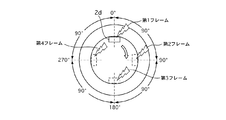
実施例1で、TPMSセンサ2(送信機2d)は、基準位置(最上点)で送信する。ここで、図10で一例を示すように、車輪1における送信機2dの回転位置(回転角度)には、受信機3が受信する電波強度が最低となるポイントないし領域(Null点)が(場合によっては複数)存在する。送信機2dがデータを送信する基準位置(最上点)がNull点の近傍に位置すると、送信されたデータを受信機3が受信することが困難となる。よって、TPMSセンサ2(送信機2d)の送信時における車輪1の回転位置(基準位置)を車体側で特定することができない場合がある。このため、オートラーニングモードにおいてTPMSセンサ2の車輪位置を精度良く推定することができなかったり、推定完了までの時間が延びたりするおそれがある。ここで、受信確率を向上させるため、TPMSセンサ2のデータを重複し、同一内容の複数のフレームとして送信機2dから送信することが考えられる。しかし、複数のフレームは異なる回転位置で送信されることとなる。このため、単にデータを重複しただけでは、受信確率が向上したとしても、受信されるフレームがどの回転位置で送信されたものであるか分らず、TPMSセンサ2の車輪位置を判定するための基準となる回転位置(歯数)を車体側で特定できなくなるという不都合がある。
In the first embodiment, the TPMS sensor 2 (
これに対し、実施例1では、TPMSセンサ2は、自身(送信機2d)の回転位置情報を含むように、複数のデータ(第1〜第3フレーム)を送信する。具体的には、図3(b)に示すように、TPMSセンサ2は、TPMSデータを重複して複数の同一内容のフレーム(第1〜第3フレーム)とし、TPMSデータの1回の送信につき、1つの基準となるフレーム(第1フレーム)を所定の回転位置で送信する。すなわち、第1フレームを所定の回転位置(最上点)で送信し、この第1フレームの送信時におけるTPMSセンサ2の回転位置(最上点)を、車輪位置判定のための基準位置とする。また、他のフレーム(第2,第3フレーム)に該フレームの送信時における送信機2dの回転位置情報を含める。具体的には、第1〜第3フレームを、所定の時間間隔(100msec,140msec)をおいて、当該フレームの送信順番を示すフレーム番号(1〜3)をそれぞれ付して、送信する。回転位置演算部4aは、第1〜第3フレームのいずれかが受信されると、そのフレーム番号(1〜3)と上記時間間隔(100msec,140msec)とに基づき、TPMSセンサ2が第1フレームを送信した基準位置(最上点)、すなわち歯数zt2を推定する。
このように、TPMSセンサ2のデータを重複し、複数のフレームとすることで、第1フレームの送信位置(最上点)がNull点の近傍に位置するような場合でも、他のフレーム(第2,第3フレーム)を受信することで、受信確率を向上できる。なお、フレームの数は3に限らず、例えば2や4以上であってもよい。また、各フレームが回転位置情報(フレーム番号)を含むことで、複数のフレームのうちいずれが受信されても、その受信情報に基づき、車体側で、送信機2dの送信時における回転位置(歯数zt2)を推定することができる。よって、各車輪1における送信機2dの送信時の回転位置を車体側でより正確に検出し、TPMSセンサ2の車輪位置をより精度良く判定することが可能となる。したがって、早期にオートラーニングモードを完了することができる。
In contrast, in the first embodiment, the
In this way, by overlapping the data of the
また、TPMSセンサ2は、基準フレーム(第1フレーム)を所定の回転位置(最上点)で送信し、回転位置演算部4aは、受信されたフレーム(例えば第2フレーム)の送信順番情報(フレーム番号)に基づいて上記所定の回転位置(最上点での歯数zt2)を推定する。すなわち、車体側でTPMSセンサ2の車輪位置を判定するための基準となる回転位置を、TPMSセンサ2が第1フレームを出力する回転位置(最上点)に設定し、この基準となる回転位置(歯数zt2)を、受信された他のフレーム(第2,第3フレーム)に基づき算出する。よって、TPMSセンサ2の構成を簡素化しつつ、車体側で、TPMSセンサ2の送信時における回転位置(歯数zt2)を推定することができる。すなわち、実施例1とは異なり、各フレームの送信時におけるTPMSセンサ2の回転位置を推定する手段を車輪1(TPMSセンサ2)の側に設け、各フレームごとに上記推定した回転位置を含めて車体側に送信することも考えられる。これに対し、実施例1では、上記のような推定手段を設けることなく、各フレームに回転位置情報として送信順番情報(フレーム番号)を含めることで、TPMSセンサ2の車輪位置を判定するための基準となる回転位置(歯数zt2)を車体側で特定することができる。よって、TPMSセンサ2の構成を簡素化して、コストの削減等を図ることができる。なお、車輪位置判定(分散特性値Xの算出)のための基準位置は、第1フレームを送信する回転位置に限らず、第2フレームを送信する回転位置や、第3フレームを送信する回転位置であってもよい。
The
ここで、各フレームを送信する時間間隔が同じである(例えば、第1,第2フレーム間の送信間隔と第2,第3フレーム間の送信間隔が共に100msecである)場合、各フレームを送信する回転位置が全て同じNull点の近傍に位置する事態も考えられる。例えば、最初の送信位置がNull点の近傍に位置し、かつ車輪1の回転周期と各フレームの送信周期とが同期するような場合には、車輪1が回転する毎に各フレームの送信位置がNull点の近傍と一致することとなり、各フレームがいずれも受信されないおそれがある。これに対し、実施例1では、送信機は、3以上のフレーム(第1〜第3フレーム)を送信し、かつ各フレームを異なる時間間隔(100msec,140msec)をおいて送信する。よって、車輪1の回転周期と各フレームの送信周期とが同期することを抑制し、以て上記事態を回避して、受信確率を向上することができる。
Here, when the time interval for transmitting each frame is the same (for example, the transmission interval between the first and second frames and the transmission interval between the second and third frames are both 100 msec), each frame is transmitted. It is also conceivable that the rotational positions to be moved are all located near the same null point. For example, when the first transmission position is located near the null point and the rotation cycle of the
なお、TPMSセンサ2が各フレームに含める該フレームの送信時における送信機2dの回転位置情報として、送信順番情報(フレーム番号)の代わりに、該フレームの送信時における送信機2dの回転位置の推定値を含むこととしてもよい。例えば、センサCU2cは、各フレームを送信する際、Gセンサ2bにより検出された遠心方向加速度の重力加速度依存成分(車輪1の各回転周期内でサンプリングされた上記成分の大きさ、符号や変化方向)に基づいて送信機2dの回転位置(回転角度)を演算し、その回転位置を、送信するフレームに付すこととしてもよい。この場合、回転位置演算部4aは、複数のフレームのいずれかが受信されると、実施例1と同様(上記式(1)に基づき)、受信されたフレームの受信開始直前と受信完了直後にそれぞれ入力される車輪速パルスのカウント値等に基づき、受信フレームの送信時における回転位置(歯数)を推定する。この推定された回転位置(歯数)と、受信されたフレームに含まれる回転位置(回転角度から換算される歯数)との対応関係に基づき、TPMSセンサ2の車輪位置を判定することができる。
上記判定に際しては、実施例1のような分散特性値Xを用いても用いなくてもよい。また、基準フレームを設けてこれを所定の回転位置(最上点等)で送信する必要はなく、任意の回転位置で各フレームを送信すればよい。言換えると、各フレームの送信時におけるTPMSセンサ2の回転位置を、車輪位置判定のための基準位置とすることができる。フレーム間の間隔(時間間隔ないし回転位置間隔)も所定値である必要はない。
実施例1では、オートラーニングモード中、各車輪1のTPMSセンサ2は、前回のTPMSデータ送信時刻から16秒経過後、自身の回転位置が所定位置(最上点等)となるのを待ってから次のTPMSデータ(基準フレーム)を送信する必要がある。これに対し、各フレームに回転位置の推定値を含める上記例では、前回の送信時刻から16秒経過した直後の任意の回転位置で、TPMSデータ(任意のフレーム)を送信することができる。よって、オートラーニングモード中、各回のTPMSデータ送信時刻において、TPMSセンサ2の車輪位置判定のためのデータをより速やかに取得することが可能であるため、より早期にTPMSセンサ2の車輪位置を判定することができる。
As the rotational position information of the
In the above determination, the dispersion characteristic value X as in the first embodiment may or may not be used. In addition, it is not necessary to provide a reference frame and transmit it at a predetermined rotational position (the highest point or the like), and each frame may be transmitted at an arbitrary rotational position. In other words, the rotational position of the
In the first embodiment, during the auto-learning mode, the
次に、効果を説明する。
実施例1のタイヤ空気圧モニター装置にあっては、以下に列挙する効果を奏する。
(1) 各タイヤの空気圧を監視するタイヤ空気圧モニター装置であって、各車輪1のタイヤに装着され、タイヤの空気圧を検出するタイヤ空気圧検出手段(圧力センサ2a)と、各車輪1に設けられ、空気圧情報を無線信号にて送信し、この無線信号に各送信機2d固有の識別情報(センサID)を含める送信機2dと、車体側に設けられ、無線信号を受信する受信機3と、各車輪1と対応して車体側に設けられ、各車輪1の回転位置(車輪速パルス)を検出する回転位置検出手段(車輪速センサ8)と、車体側に設けられ、送信機2dからの無線信号の受信情報(受信完了時刻t4)と、回転位置検出手段(車輪速センサ8)からの車輪1の回転位置情報(歯数zt1,zt5)とに基づいて、送信機2dの送信時(送信指令時刻t2)における回転位置(歯数zt2)を推定する車体側回転位置推定手段(回転位置演算部4a)と、推定された回転位置(歯数zt2)と無線信号に含まれる識別情報(センサID)とに基づき、送信機2dが設けられた車輪1の位置(FL〜RR)を判定する車輪位置判定手段(車輪位置判定部4c)と、を備え、送信機2dは、無線信号を重複して複数のフレーム(第1〜第3フレーム)とし、各フレームを互いに間隔をおいて送信し、各フレームに該フレームの送信時における送信機2dの回転位置情報(フレーム番号)を含める。
よって、受信確率を向上して、送信機2dの車輪位置をより精度良く判定することができる。
Next, the effect will be described.
The tire pressure monitoring device of the first embodiment has the following effects.
(1) A tire air pressure monitoring device for monitoring the air pressure of each tire, which is mounted on the tire of each
Therefore, the reception probability can be improved and the wheel position of the
(2) 各車輪1に、各フレームの送信時における送信機2dの回転位置を推定する車輪側回転位置推定手段(Gセンサ2b、センサCU2c)を設け、送信機2dは、回転位置情報として、前記推定された回転位置を各フレームに含めることとしてもよい。
この場合、任意の回転位置で各フレームを送信すればよいため、より早期に送信機2dの車輪位置を判定することができる。
(2) Each
In this case, since it is only necessary to transmit each frame at an arbitrary rotational position, the wheel position of the
(3) 送信機2dは、複数のフレーム(第1〜第3フレーム)のうち所定の1つの基準フレーム(例えば第1フレーム)を所定の回転位置(最上点)で送信し、各フレームを互いに所定の間隔(時間間隔100msec,140msec)をおいて送信し、回転位置情報として、各フレームに該フレームの送信順番情報(フレーム番号)を含め、車体側回転位置推定手段(回転位置演算部4a)は、複数のフレームのうち受信されたもの(例えば第2フレーム)の受信情報(受信完了時刻t4' およびフレーム番号)に基づいて上記所定の回転位置(最上点での歯数zt2)を推定し、車輪位置判定手段(車輪位置判定部4c)は、推定された所定の回転位置(歯数zt2)に基づき、送信機2dが設けられた車輪1の位置(FL〜RR)を判定する。
すなわち、各フレーム(第2、第3フレーム)に付された送信順番情報(フレーム番号)は、所定の間隔(時間間隔100msec,140msec)の情報と組み合わさって、該フレーム(第2、第3フレーム)の送信時における送信機2dの回転位置情報を表す。よって、各車輪1に、各フレームの送信時における送信機2dの回転位置を推定する手段を設ける必要がなく、構成を簡素化することができる。
(3) The
That is, transmission order information (frame number) attached to each frame (second and third frames) is combined with information of a predetermined interval (
(4) 送信機2dは、各フレーム(第1〜第3フレーム)を互いに所定の時間間隔(100msec,140msec)をおいて送信する。
よって、車体側回転位置推定手段(回転位置演算部4a)は、複数のフレームのうち受信されたもの(例えば第2フレーム)の受信情報(受信完了時刻t4' およびフレーム番号)に基づいて、所定の回転位置(最上点での歯数zt2)を推定することができる。
(4) The
Accordingly, the vehicle body side rotational position estimating means (the rotational
(5) 送信機2dは、3以上のフレーム(第1〜第3フレーム)を送信し、各フレームを異なる時間間隔(100msec,140msec)をおいて送信する。
よって、車輪1の回転周期と各フレームの送信周期とが同期して各フレームの送信位置がNull点の近傍と一致する事態を抑制することで、受信確率をより向上することができる。
(5) The
Therefore, the reception probability can be further improved by suppressing the situation where the rotation period of the
(6) 回転位置検出手段(車輪速センサ8,ABSCU6)は、通信線(CAN通信線7)へ所定の時間間隔(周期20msec)で車輪1の回転位置情報(車輪速パルスのカウント値)を出力し、車体側回転位置推定手段(回転位置演算部4a)は、受信されたフレーム(例えば第2フレーム)の受信開始(時刻t2')直前と受信完了(時刻t4')直後にそれぞれ通信線(CAN通信線7)を介して入力される車輪1の回転位置(歯数)と、該車輪1の回転位置の入力時刻(t1',t5')と、受信開始時刻(時刻t3')または受信完了時刻(時刻t4')とに基づいて、送信機2dの送信時における回転位置(歯数zt2)を推定する。
よって、既存のシステムを利用してコスト増大を抑制しつつ、TPMSセンサ2の車輪位置を精度良く推定することができる。
(6) The rotational position detection means (wheel speed sensor 8, ABSCU6) sends the rotational position information (wheel speed pulse count value) of the
Therefore, it is possible to accurately estimate the wheel position of the
〔実施例2〕
実施例2では、定位置送信モードにおいて、各TPMSセンサ2は、自身(送信機2d)の回転位置情報を含む複数のデータ(例えば第1〜第4フレーム)を送信する。図11に示すように、TPMSセンサ2は、TPMSデータの1回の送信につき、1つのフレーム(第1フレーム)を所定の回転位置(基準位置 = 最上点)で送信し、各フレームを互いに所定の回転位置間隔(例えば90度)をおいて送信する。また、他のフレーム(第2〜第4フレーム)に該フレームの送信時における送信機2dの回転位置情報を含める。具体的には、TPMSセンサ2は、各フレームに該フレームの送信順番情報(フレーム番号)を含める。回転位置演算部4aは、第1〜第4フレームのいずれかが受信されると、そのフレーム番号(1〜4)と上記回転位置間隔(90度)とに基づき、TPMSセンサ2が第1フレームを送信した基準位置(最上点)、すなわち歯数zt2を推定する。
例えば、回転位置演算部4aは、受信されたフレームが第3フレームである場合、第3フレームが送信された回転位置(歯数)を、上記式(1)と同様の方法で算出する。この算出した回転位置(歯数)から、第1フレームから第3フレームまでの回転位置間隔(90度×2 = 180度に相当するロータの歯数)を減算して、第1フレームが送信された所定の回転位置(歯数zt2)を算出する。
他の構成は実施例1と同様であるため、説明を省略する。
(Example 2)
In the second embodiment, in the fixed position transmission mode, each
For example, when the received frame is the third frame, the rotational
Since other configurations are the same as those of the first embodiment, the description thereof is omitted.
よって、実施例1と同様、受信確率を向上しつつ、TPMSセンサ2の車輪位置を精度良く推定し、早期にオートラーニングモードを完了することができる。
なお、受信確率を向上するため、フレーム間の回転位置間隔を異ならせたり、フレーム数を増やしたりすることとしてもよい。
その他、各フレームに含める回転位置情報として、該フレームの送信時における送信機2dの回転位置の(センサCU2cによる)推定値を含んでもよい。この場合、第1フレームを送信する基準位置は特定の回転位置(最上点)に限られない。
Therefore, as in the first embodiment, it is possible to accurately estimate the wheel position of the
In order to improve the reception probability, the rotation position interval between frames may be varied or the number of frames may be increased.
In addition, the rotational position information included in each frame may include an estimated value (by the sensor CU2c) of the rotational position of the
実施例2のタイヤ空気圧モニター装置にあっては、以下の効果を奏する。
(1) 送信機2dは、各フレーム(第1〜第4フレーム)を互いに所定の回転位置間隔(例えば90度)をおいて送信する。
よって、各フレーム(第2、第3フレーム)に付された送信順番情報(フレーム番号)は、所定の回転位置間隔(90度)の情報と組み合わさって、該フレーム(第2、第3フレーム)の送信時における送信機2dの回転位置情報を表す。このため、車体側回転位置推定手段(回転位置演算部4a)は、複数のフレームのうち受信されたもの(例えば第2フレーム)の受信情報(受信完了時刻t4' およびフレーム番号)に基づいて、所定の回転位置(最上点での歯数zt2)を推定することができる。
The tire air pressure monitoring apparatus according to the second embodiment has the following effects.
(1) The
Therefore, the transmission order information (frame number) attached to each frame (second and third frames) is combined with information of a predetermined rotation position interval (90 degrees) to combine the frames (second and third frames). ) Represents the rotational position information of the
〔実施例3〕
実施例3では、定位置送信モードにおいて、各TPMSセンサ2は、TPMSデータの1回の送信につき、自身(送信機2d)の回転位置情報を含む複数のフレーム(例えば第1〜第3フレーム)を複数組(例えば第1〜第4組)送信する。実施例3では、4つの組を設け、各組がそれぞれ第1〜第3フレームを有する。よって、TPMSセンサ2が送信するフレーム数は合計で12(= 4×3)になる。
図12に示すように、TPMSセンサ2(送信機2d)は、互いに所定の回転位置間隔(例えば90度)をおいて複数(4つ)設けられた所定の回転位置(各組の基準位置)で、対応する組の1つのフレーム(第1フレーム)を送信する。具体的には、センサCU2cは、定位置送信モード中、Gセンサ2bにより検出された遠心方向加速度の重力加速度依存成分に基づいてTPMSセンサ2(送信機2d)の回転位置を演算し、第1組の第1フレームを最上点(0度)で送信し、第2組の第1フレームを最後点(90度)で送信し、第3組の第1フレームを最下点(180度)で送信し、第4組の第1フレームを最前点(270度)で送信する。TPMSセンサ2は、各組の基準位置(最上点、最後点、最下点、最前点)で各組の第1フレームを送信した後、同じ組の他のフレーム(第2,第3フレーム)を、例えば実施例1と同様の方法で送信する。すなわち、所定の時間間隔(100msec,140msec)をおいて、当該フレームの送信順番を示すフレーム番号(2,3)をそれぞれ付して、第2,第3フレームを送信する。さらに、各フレームには、そのフレームがどの組に属するかを示す情報(組番号、ないし各組の基準位置に応じたフラグ)を付す。
Example 3
In the third embodiment, in the fixed position transmission mode, each
As shown in FIG. 12, the TPMS sensor 2 (
例えば、TPMSセンサ2は、第2組の第1フレームを第2組の基準位置(90度の最後点)で送信し、その100msec後に第2フレームを送信し、その140msec後に第3フレームを送信する。回転位置演算部4aは、第2組の第1〜第3フレームのいずれかが受信されると、そのフレーム番号(1〜3)と上記時間間隔(100msec,140msec)とに基づき、上記式(1)と同様の方法で、第2組の基準位置(最後点)、すなわち歯数zt2を推定する。また、回転位置演算部4aは、受信されたフレームに付された組番号に基づき、上記推定した第2組の基準位置(最後点での歯数)を、第1組の基準位置(最上点での歯数zt2)に換算する。具体的には、第1,第2組間の回転位置間隔(90度)に相当する歯数を、推定した第2組の基準位置(最後点)の歯数zt2から減算することで、第1組の基準位置(最上点)の歯数zt2を算出する。
他の組(第3,第4組)のフレームが受信された場合も同様に、第1組の基準位置(最上点)の歯数zt2を演算する。分散演算部4bは、算出された第1組の基準位置(最上点)の歯数zt2の分散特性値Xを演算する。すなわち、算出される第1組の基準位置(最上点)を基準として、TPMSセンサ2の車輪位置を判定する。
他の構成は実施例1と同様であるため、説明を省略する。
For example, the
Similarly, when the frames of other groups (third and fourth groups) are received, the number of teeth z t2 of the reference position (top point) of the first group is calculated. The
Since other configurations are the same as those of the first embodiment, the description thereof is omitted.
次に、作用を説明する。
Null点は一箇所とは限らず、複数箇所存在する場合もある。この場合、実施例1のように各フレームを異なる時間間隔(100msec,140msec)をおいて送信しても、車輪1の回転周期(回転数)、言い換えると車速によっては、全てのフレームの送信位置が(複数ある)Null点の近傍と一致し、各フレームがいずれも受信されない事態も想定しうる。これに対し、実施例3では、上記のように構成したことで、上記のような事態を回避できる。よって、フレームの受信確率をより向上しつつ、TPMSセンサ2の車輪位置を判定するための基準となる回転位置(第1組の基準位置での歯数)を、より確実に、車体側で特定することができる。
なお、各組ごとに基準位置の歯数の分散特性値Xを演算することとしてもよい。実施例3では、受信された全てのデータを第1組の基準位置(最上点での歯数)に換算することで、より速やかに自輪と他輪の分散特性値Xに有意な差を出すことができる。よって、TPMSセンサ2の車輪位置をより短時間で精度良く推定することができる。なお、車輪位置判定(分散特性値Xの算出)のための基準位置を、第1組の基準位置(最上点)に限らず、他の組(第2組等)の基準位置(最後点等)に集約することとしてもよい。
Next, the operation will be described.
Null points are not limited to one place, and there may be multiple places. In this case, even if each frame is transmitted at different time intervals (100 msec, 140 msec) as in the first embodiment, the transmission position of all the frames depends on the rotation cycle (number of rotations) of the
Note that the dispersion characteristic value X of the number of teeth at the reference position may be calculated for each group. In Example 3, all the received data is converted into the first set of reference positions (the number of teeth at the uppermost point), so that a significant difference in the dispersion characteristic value X between the own wheel and the other wheel can be obtained more quickly. Can be put out. Therefore, the wheel position of the
TPMSセンサ2(送信機2d)は、実施例2と同様、各組のフレーム(第1〜第3フレーム)を所定の回転位置間隔をおいて送信することとしてもよい。
また、TPMSセンサ2は、組ごとに第1フレームを送信する所定の回転位置(各組の基準位置)を、互いに所定の時間間隔をおいて設けることとしてもよい。この場合も、上記所定の時間間隔分の歯数を減算することで、第1組の基準位置(最上点)の歯数を演算することができる。実施例3では、各組の基準位置を、互いに所定の回転位置間隔をおいて設けることとしたため、演算を簡略化することができる。
その他、各フレームに含める回転位置情報として、該フレームの送信時における送信機2dの回転位置の(センサCU2cによる)推定値を含んでもよい。この場合、各組の第1フレームを送信する基準位置は特定の回転位置(最上点等)に限られない。
また、組の数は、4に限らず、2や3,5等、他の数であってもよい。
As in the second embodiment, the TPMS sensor 2 (
Further, the
In addition, the rotational position information included in each frame may include an estimated value (by the sensor CU2c) of the rotational position of the
Further, the number of sets is not limited to four, and may be other numbers such as 2, 3, 5, and the like.
実施例3のタイヤ空気圧モニター装置にあっては、以下に列挙する効果を奏する。
(1) 送信機2dは、複数のフレーム(第1〜第3フレーム)を複数組(第1〜第4組)送信し、所定の間隔(90度)をおいて組ごとに設けた所定の回転位置(最上点、最後点、最下点、最前点)で各組の基準フレーム(例えば第1フレーム)を送信する。
よって、受信確率をより向上して、送信機2dの車輪位置の判定基準となる回転位置(第1組の基準位置での歯数)を、より確実に特定することができる。
The tire pressure monitoring device of the third embodiment has the following effects.
(1)
Therefore, the reception probability can be further improved, and the rotational position (the number of teeth at the first set of reference positions) that serves as a determination criterion for the wheel position of the
(2) 送信機2dは、各フレーム(第1〜第3フレーム)に該フレームがどの組に属するかという組情報(組番号)を含め、車体側回転位置推定手段(回転位置演算部4a)は、受信されたフレームについて推定した該フレームが属する組(例えば第2組)の所定の回転位置(最後点での歯数)と組情報(組番号)とに基づき、複数の組(第1〜第4組)のうち所定の1つの基準組(例えば第1組)の所定の回転位置(最上点での歯数)を推定し、車輪位置判定手段(車輪位置判定部4c)は、推定された基準組(第1組)の所定の回転位置(最上点での歯数zt2)に基づき、送信機2dが設けられた車輪1の位置を判定する。
よって、受信された全てのデータを1つの基準組(第1組)の基準位置(最上点での歯数zt2)に換算することで、送信機2dの車輪位置をより短時間で精度良く推定することができる。
(2) The
Therefore, by converting all the received data to the reference position (number of teeth z t2 at the highest point) of one reference group (first group), the wheel position of the
〔他の実施例〕
以上、本発明を実施するための最良の形態を、図面に基づく実施例により説明したが、本発明の具体的な構成は、実施例に限定されるものではなく、発明の要旨を逸脱しない範囲の設計変更等があっても本発明に含まれる。
例えば、実施例では、回転位置検出手段として車輪速センサを用いた例を示したが、駆動源としてインホイールモータを備えた車両では、モータのレゾルバを用いて回転角度を検出してもよい。
[Other Examples]
The best mode for carrying out the present invention has been described with reference to the embodiments based on the drawings. However, the specific configuration of the present invention is not limited to the embodiments, and does not depart from the gist of the invention. Such design changes are included in the present invention.
For example, in the embodiment, an example is shown in which a wheel speed sensor is used as the rotational position detecting means. However, in a vehicle equipped with an in-wheel motor as a drive source, the rotational angle may be detected using a motor resolver.
1 車輪
2a 圧力センサ(タイヤ空気圧検出手段)
2d 送信機
3 受信機
4a 回転位置演算部(車体側回転位置推定手段)
4c 車輪位置判定部(車輪位置判定手段)
8 車輪速センサ(回転位置検出手段)
1 wheel
2a Pressure sensor (Tire pressure detection means)
2d transmitter
3 Receiver
4a Rotational position calculation unit (vehicle side rotational position estimation means)
4c Wheel position determination unit (wheel position determination means)
8 Wheel speed sensor (rotation position detection means)
Claims (8)
各車輪のタイヤに装着され、該タイヤの空気圧を検出するタイヤ空気圧検出手段と、
各車輪に設けられ、前記空気圧情報を無線信号にて送信し、該無線信号に各送信機固有の識別情報を含める送信機と、
車体側に設けられ、前記無線信号を受信する受信機と、
各車輪と対応して車体側に設けられ、各車輪の回転位置を検出すると共に、通信線へ所定の時間間隔で前記車輪の回転位置情報を出力する回転位置検出手段と、
車体側に設けられ、前記送信機からの前記無線信号の受信情報と、前記通信線を介して入力される前記車輪の回転位置情報とに基づいて、前記送信機の送信時における回転位置を推定する車体側回転位置推定手段と、
前記推定された回転位置と前記無線信号に含まれる前記識別情報とに基づき、前記送信機が設けられた車輪の位置を判定する車輪位置判定手段と、を備え、
前記送信機は、前記無線信号を重複して複数のフレームとし、各フレームを互いに間隔をおいて送信し、各フレームに該フレームの送信時における前記送信機の回転位置情報を含め、
前記車体側回転位置推定手段は、
前記複数のフレームのうち受信されたものの受信情報に基づいて、前記送信機の送信時における回転位置を推定し、
受信されたフレームの受信開始直前と受信完了直後にそれぞれ前記通信線を介して入力される前記車輪の回転位置と、該車輪の回転位置の入力時刻と、前記受信開始時刻または前記受信完了時刻とに基づいて、前記送信機の送信時における回転位置を推定する
ことを特徴とするタイヤ空気圧モニター装置。 A tire pressure monitoring device for monitoring the pressure of each tire,
Tire pressure detecting means mounted on the tire of each wheel and detecting the air pressure of the tire;
A transmitter provided on each wheel, transmitting the air pressure information by a radio signal, and including identification information unique to each transmitter in the radio signal;
A receiver provided on the vehicle body side for receiving the radio signal;
Rotation position detecting means provided on the vehicle body side corresponding to each wheel, detecting the rotation position of each wheel, and outputting the rotation position information of the wheel at a predetermined time interval to a communication line ;
Estimated rotational position at the time of transmission of the transmitter based on reception information of the radio signal from the transmitter and rotational position information of the wheel input via the communication line provided on the vehicle body side Vehicle body side rotational position estimating means,
Wheel position determination means for determining the position of the wheel provided with the transmitter based on the estimated rotational position and the identification information included in the radio signal,
The transmitter overlaps the radio signal into a plurality of frames, transmits each frame at an interval, and includes the rotational position information of the transmitter at the time of transmission of the frame in each frame ,
The vehicle body side rotational position estimating means is
Based on the received information of the received one of the plurality of frames, estimate the rotational position at the time of transmission of the transmitter,
The rotational position of the wheel that is input via the communication line immediately before the start of reception of the received frame and immediately after the completion of reception, the input time of the rotational position of the wheel, and the reception start time or the reception completion time Based on the above , a tire air pressure monitor device that estimates a rotational position at the time of transmission of the transmitter .
各車輪に、各フレームの送信時における前記送信機の回転位置を推定する車輪側回転位置推定手段を設け、
前記送信機は、前記回転位置情報として、前記推定された回転位置を各フレームに含めることを特徴とするタイヤ空気圧モニター装置。 In the tire pressure monitoring device according to claim 1,
Each wheel is provided with a wheel side rotational position estimating means for estimating the rotational position of the transmitter at the time of transmission of each frame,
The transmitter includes the estimated rotational position in each frame as the rotational position information.
前記送信機は、前記複数のフレームのうち所定の1つの基準フレームを所定の回転位置で送信し、各フレームを互いに所定の間隔をおいて送信し、前記回転位置情報として、各フレームに該フレームの送信順番情報を含め、
前記車体側回転位置推定手段は、前記複数のフレームのうち受信されたものの受信情報に基づいて前記所定の回転位置を推定し、
前記車輪位置判定手段は、前記推定された前記所定の回転位置に基づき、前記送信機が設けられた車輪の位置を判定する
ことを特徴とするタイヤ空気圧モニター装置。 In the tire pressure monitoring device according to claim 1,
The transmitter transmits a predetermined one reference frame among the plurality of frames at a predetermined rotational position, transmits each frame at a predetermined interval, and transmits the frame to each frame as the rotational position information. Including transmission order information for
The vehicle body side rotational position estimating means estimates the predetermined rotational position based on reception information of the received one of the plurality of frames;
The wheel position determination means determines a position of a wheel provided with the transmitter based on the estimated predetermined rotational position.
前記送信機は、各フレームを互いに所定の時間間隔をおいて送信することを特徴とするタイヤ空気圧モニター装置。 In the tire pressure monitoring device according to claim 3,
The tire pressure monitoring device, wherein the transmitter transmits each frame at a predetermined time interval.
前記送信機は、3以上のフレームを送信し、各フレームを異なる時間間隔をおいて送信することを特徴とするタイヤ空気圧モニター装置。 In the tire pressure monitoring device according to claim 4,
The tire pressure monitoring apparatus, wherein the transmitter transmits three or more frames and transmits each frame at different time intervals.
前記送信機は、各フレームを互いに所定の回転位置間隔をおいて送信することを特徴とするタイヤ空気圧モニター装置。 In the tire pressure monitoring device according to claim 3,
The tire pressure monitoring device, wherein the transmitter transmits each frame at a predetermined rotational position interval.
各車輪のタイヤに装着され、該タイヤの空気圧を検出するタイヤ空気圧検出手段と、
各車輪に設けられ、前記空気圧情報を無線信号にて送信し、該無線信号に各送信機固有の識別情報を含める送信機と、
車体側に設けられ、前記無線信号を受信する受信機と、
各車輪と対応して車体側に設けられ、各車輪の回転位置を検出すると共に、通信線へ所定の時間間隔で前記車輪の回転位置情報を出力する回転位置検出手段と、
車体側に設けられ、前記送信機からの前記無線信号の受信情報と、前記通信線を介して入力される前記車輪の回転位置情報とに基づいて、前記送信機の送信時における回転位置を推定する車体側回転位置推定手段と、
前記推定された回転位置と前記無線信号に含まれる前記識別情報とに基づき、前記送信機が設けられた車輪の位置を判定する車輪位置判定手段と、を備え、
前記送信機は、前記無線信号を重複して複数のフレームとし、前記複数のフレームのうち所定の1つの基準フレームを所定の回転位置で送信し、各フレームを互いに所定の間隔をおいて送信し、各フレームに該フレームの送信時における前記送信機の回転位置情報として該フレームの送信順番情報を含め、
前記車体側回転位置推定手段は、前記複数のフレームのうち受信されたものの受信情報に基づいて前記所定の回転位置を推定し、
前記車輪位置判定手段は、前記推定された前記所定の回転位置に基づき、前記送信機が設けられた車輪の位置を判定し、
前記送信機は、前記複数のフレームを複数組送信し、所定の間隔をおいて組ごとに設けた前記所定の回転位置で各組の前記基準フレームを送信する
ことを特徴とするタイヤ空気圧モニター装置。 A tire pressure monitoring device for monitoring the pressure of each tire,
Tire pressure detecting means mounted on the tire of each wheel and detecting the air pressure of the tire;
A transmitter provided on each wheel, transmitting the air pressure information by a radio signal, and including identification information unique to each transmitter in the radio signal;
A receiver provided on the vehicle body side for receiving the radio signal;
Rotation position detecting means provided on the vehicle body side corresponding to each wheel, detecting the rotation position of each wheel, and outputting the rotation position information of the wheel at a predetermined time interval to a communication line;
Estimated rotational position at the time of transmission of the transmitter based on reception information of the radio signal from the transmitter and rotational position information of the wheel input via the communication line provided on the vehicle body side Vehicle body side rotational position estimating means,
Wheel position determination means for determining the position of the wheel provided with the transmitter based on the estimated rotational position and the identification information included in the radio signal,
The transmitter overlaps the radio signal into a plurality of frames, transmits a predetermined reference frame of the plurality of frames at a predetermined rotational position, and transmits each frame at a predetermined interval. , Including transmission order information of the frames as rotational position information of the transmitter at the time of transmission of the frames in each frame,
The vehicle body side rotational position estimating means estimates the predetermined rotational position based on reception information of the received one of the plurality of frames;
The wheel position determination means determines a position of a wheel provided with the transmitter based on the estimated predetermined rotational position,
The transmitter of the plurality of frames and a plurality of sets transmission, tire air pressure monitoring system and transmits the reference frame of each set at the predetermined rotational position which is provided for each set with a predetermined gap .
前記送信機は、各フレームに該フレームがどの組に属するかという組情報を含め、
前記車体側回転位置推定手段は、受信されたフレームについて推定した該フレームが属する組の前記所定の回転位置と前記組情報とに基づき、前記複数の組のうち所定の1つの基準組の前記所定の回転位置を推定し、
前記車輪位置判定手段は、前記推定された前記基準組の前記所定の回転位置に基づき、前記送信機が設けられた車輪の位置を判定する
ことを特徴とするタイヤ空気圧モニター装置。 In the tire pressure monitoring device according to claim 7,
The transmitter includes set information indicating which set the frame belongs to in each frame,
The vehicle body side rotational position estimating means is configured to determine the predetermined reference group of the predetermined one of the plurality of sets based on the predetermined rotational position of the set to which the frame estimated for the received frame belongs and the set information. Estimate the rotational position of
The tire pressure monitoring device, wherein the wheel position determination means determines a position of a wheel provided with the transmitter based on the estimated rotation position of the estimated reference set.
Priority Applications (10)
| Application Number | Priority Date | Filing Date | Title |
|---|---|---|---|
| JP2011115005A JP5736959B2 (en) | 2011-05-23 | 2011-05-23 | Tire pressure monitoring device |
| CN201280021606.2A CN103582577B (en) | 2011-05-17 | 2012-02-20 | Tire air pressure monitor device |
| MX2013012633A MX340372B (en) | 2011-05-17 | 2012-02-20 | Tire air pressure monitor device. |
| US14/117,765 US9322744B2 (en) | 2011-05-17 | 2012-02-20 | Tire air pressure monitor device |
| EP12786626.7A EP2711204B1 (en) | 2011-05-17 | 2012-02-20 | Tire air pressure monitor device |
| RU2013155920/11A RU2549577C1 (en) | 2011-05-17 | 2012-02-20 | Tire air pressure monitoring device |
| MYPI2013004004A MY165692A (en) | 2011-05-17 | 2012-02-20 | Tire pressure monitoring device |
| BR112013028300A BR112013028300B1 (en) | 2011-05-17 | 2012-02-20 | tire pressure monitoring device |
| KR1020137030086A KR20130130878A (en) | 2011-05-17 | 2012-02-20 | Tire air pressure monitor device |
| PCT/JP2012/053976 WO2012157308A1 (en) | 2011-05-17 | 2012-02-20 | Tire air pressure monitor device |
Applications Claiming Priority (1)
| Application Number | Priority Date | Filing Date | Title |
|---|---|---|---|
| JP2011115005A JP5736959B2 (en) | 2011-05-23 | 2011-05-23 | Tire pressure monitoring device |
Publications (3)
| Publication Number | Publication Date |
|---|---|
| JP2012240615A JP2012240615A (en) | 2012-12-10 |
| JP2012240615A5 JP2012240615A5 (en) | 2013-09-26 |
| JP5736959B2 true JP5736959B2 (en) | 2015-06-17 |
Family
ID=47462744
Family Applications (1)
| Application Number | Title | Priority Date | Filing Date |
|---|---|---|---|
| JP2011115005A Active JP5736959B2 (en) | 2011-05-17 | 2011-05-23 | Tire pressure monitoring device |
Country Status (1)
| Country | Link |
|---|---|
| JP (1) | JP5736959B2 (en) |
Families Citing this family (8)
| Publication number | Priority date | Publication date | Assignee | Title |
|---|---|---|---|---|
| JP2014226941A (en) * | 2013-05-17 | 2014-12-08 | 太平洋工業株式会社 | Wheel position determination device |
| JP6084515B2 (en) * | 2013-05-24 | 2017-02-22 | 太平洋工業株式会社 | Wheel position determination device |
| DE102013211152A1 (en) * | 2013-06-14 | 2014-12-18 | Continental Automotive Gmbh | Method and device for locating wheels of a vehicle and tire pressure monitoring system |
| JP6257992B2 (en) * | 2013-10-10 | 2018-01-10 | 太平洋工業株式会社 | Tire position determination system |
| JP2015101208A (en) | 2013-11-25 | 2015-06-04 | 株式会社東海理化電機製作所 | Tire position deciding system |
| JP2015131546A (en) * | 2014-01-10 | 2015-07-23 | 株式会社東海理化電機製作所 | Tire position registration system |
| KR101979777B1 (en) * | 2017-08-07 | 2019-05-17 | 전남대학교산학협력단 | Tire location registration method and apparatus using Inter Frame Spacing pattern of TPMS sensor |
| CN115461233A (en) * | 2020-11-19 | 2022-12-09 | 太平洋工业株式会社 | Receiver, transmitter, and transmission/reception system |
Family Cites Families (7)
| Publication number | Priority date | Publication date | Assignee | Title |
|---|---|---|---|---|
| DE19734323B4 (en) * | 1997-08-08 | 2004-05-06 | Continental Aktiengesellschaft | Method for carrying out the assignment of the wheel position to tire pressure control devices in a tire pressure control system of a motor vehicle |
| AU2003257605A1 (en) * | 2002-08-30 | 2004-03-19 | Bridgestone Corporation | Wheel condition-monitoring system |
| JP3975973B2 (en) * | 2003-06-05 | 2007-09-12 | トヨタ自動車株式会社 | Wheel-body communication system |
| JP2006123725A (en) * | 2004-10-28 | 2006-05-18 | Nissan Motor Co Ltd | Tire pneumatic pressure monitoring device |
| JP2006138803A (en) * | 2004-11-15 | 2006-06-01 | Toyota Motor Corp | Apparatus for acquiring wheel condition and method of communicating wheel condition |
| JP5182030B2 (en) * | 2008-11-19 | 2013-04-10 | 日産自動車株式会社 | Tire pressure monitoring device and tire pressure monitoring method |
| US8332103B2 (en) * | 2009-09-22 | 2012-12-11 | Schrader Electronics Ltd. | Vehicle wheel auto-location using wheel phase angle information |
-
2011
- 2011-05-23 JP JP2011115005A patent/JP5736959B2/en active Active
Also Published As
| Publication number | Publication date |
|---|---|
| JP2012240615A (en) | 2012-12-10 |
Similar Documents
| Publication | Publication Date | Title |
|---|---|---|
| WO2012157308A1 (en) | Tire air pressure monitor device | |
| KR101560960B1 (en) | Tire air pressure transmission device and tire air pressure monitor system | |
| JP5736959B2 (en) | Tire pressure monitoring device | |
| JP5736948B2 (en) | Tire pressure monitoring system | |
| JP5574044B2 (en) | Tire pressure monitoring device | |
| JP5736951B2 (en) | Tire pressure monitoring device | |
| JP5853402B2 (en) | Tire pressure monitoring device | |
| JP5590227B2 (en) | Tire pressure monitoring device | |
| JPWO2013133307A1 (en) | Tire pressure monitoring device | |
| JP5741765B2 (en) | Tire pressure monitoring device | |
| JP5741766B2 (en) | Tire pressure monitoring device | |
| JP5741768B2 (en) | Tire pressure monitoring device | |
| JP5896014B2 (en) | Tire pressure monitoring device |
Legal Events
| Date | Code | Title | Description |
|---|---|---|---|
| A521 | Written amendment |
Free format text: JAPANESE INTERMEDIATE CODE: A523 Effective date: 20130807 |
|
| A621 | Written request for application examination |
Free format text: JAPANESE INTERMEDIATE CODE: A621 Effective date: 20140318 |
|
| TRDD | Decision of grant or rejection written | ||
| A01 | Written decision to grant a patent or to grant a registration (utility model) |
Free format text: JAPANESE INTERMEDIATE CODE: A01 Effective date: 20150324 |
|
| A61 | First payment of annual fees (during grant procedure) |
Free format text: JAPANESE INTERMEDIATE CODE: A61 Effective date: 20150406 |
|
| R151 | Written notification of patent or utility model registration |
Ref document number: 5736959 Country of ref document: JP Free format text: JAPANESE INTERMEDIATE CODE: R151 |