JP5735789B2 - Fundus photographing device - Google Patents
Fundus photographing device Download PDFInfo
- Publication number
- JP5735789B2 JP5735789B2 JP2010269810A JP2010269810A JP5735789B2 JP 5735789 B2 JP5735789 B2 JP 5735789B2 JP 2010269810 A JP2010269810 A JP 2010269810A JP 2010269810 A JP2010269810 A JP 2010269810A JP 5735789 B2 JP5735789 B2 JP 5735789B2
- Authority
- JP
- Japan
- Prior art keywords
- fundus
- light
- scanning
- length
- image
- Prior art date
- Legal status (The legal status is an assumption and is not a legal conclusion. Google has not performed a legal analysis and makes no representation as to the accuracy of the status listed.)
- Active
Links
- 230000003287 optical effect Effects 0.000 claims description 90
- 238000003384 imaging method Methods 0.000 claims description 67
- 238000005259 measurement Methods 0.000 claims description 65
- 238000012937 correction Methods 0.000 claims description 14
- 210000004220 fundus oculi Anatomy 0.000 claims description 5
- 230000004907 flux Effects 0.000 claims 1
- 210000001508 eye Anatomy 0.000 description 38
- 230000004323 axial length Effects 0.000 description 36
- 238000000034 method Methods 0.000 description 8
- 238000010586 diagram Methods 0.000 description 7
- 230000004075 alteration Effects 0.000 description 5
- 238000012014 optical coherence tomography Methods 0.000 description 5
- 230000002093 peripheral effect Effects 0.000 description 5
- 238000012360 testing method Methods 0.000 description 5
- 238000012545 processing Methods 0.000 description 4
- 238000004364 calculation method Methods 0.000 description 3
- 238000011158 quantitative evaluation Methods 0.000 description 3
- 210000005252 bulbus oculi Anatomy 0.000 description 2
- 230000003247 decreasing effect Effects 0.000 description 2
- 238000004088 simulation Methods 0.000 description 2
- 238000003325 tomography Methods 0.000 description 2
- 238000004458 analytical method Methods 0.000 description 1
- 239000012472 biological sample Substances 0.000 description 1
- 238000004891 communication Methods 0.000 description 1
- 230000008602 contraction Effects 0.000 description 1
- 238000002474 experimental method Methods 0.000 description 1
- 238000010191 image analysis Methods 0.000 description 1
- 239000003550 marker Substances 0.000 description 1
- 238000012986 modification Methods 0.000 description 1
- 230000004048 modification Effects 0.000 description 1
- 210000001747 pupil Anatomy 0.000 description 1
- 238000004445 quantitative analysis Methods 0.000 description 1
- 210000001525 retina Anatomy 0.000 description 1
- 238000012546 transfer Methods 0.000 description 1
- 210000001835 viscera Anatomy 0.000 description 1
Images


Description
本発明は、被検者眼の眼底を撮影する眼底撮影装置に関する。 The present invention relates to a fundus imaging apparatus that images the fundus of a subject's eye.
光走査部を用いて眼底上で測定光を走査させ眼底像を得る装置として、眼底断層像撮影装置(例えば、光断層干渉計(Optical Coherence Tomography:OCT))、眼底正面像撮影装置(例えば、走査型検眼装置(Scanning Laser Opthalmoscope:SLO))などが知られている。 As an apparatus for scanning the measurement light on the fundus using the optical scanning unit to obtain a fundus image, a fundus tomography apparatus (for example, optical tomography (OCT)), a fundus front image capturing apparatus (for example, Scanning laser opthalmoscope (SLO) and the like are known.
ところで、上記のような装置では、所定の走査画角にて眼底像が撮影される。しかしながら、同じ走査画角であっても、撮影位置によってスキャン長が変わってしまう場合があり、このような場合、眼底上の撮像範囲が変化してしまう。これは、光学系に収差がある、眼底が曲面形状であることが原因として考えられる。 By the way, in the apparatus as described above, a fundus image is taken at a predetermined scanning field angle. However, even with the same scanning angle of view, the scan length may change depending on the shooting position. In such a case, the imaging range on the fundus changes. This is considered due to the fact that the optical system has aberration and the fundus has a curved shape.
通常、モニタ上においては、眼底のどの撮影位置で断層画像を撮影しても、同じ撮像範囲で撮像されたように断層画像が表示されている。しかし、実際に撮像された断層画像は、撮影位置によって取得される撮像範囲が異なる。このため、例えば、病変部等に対し、眼底上の距離を測定する場合、定量的な評価が困難となる。 In general, on a monitor, a tomographic image is displayed as if it was captured in the same imaging range no matter what tomographic position of the fundus was captured. However, the actually captured tomographic image has a different imaging range depending on the imaging position. For this reason, for example, when measuring the distance on the fundus of a lesioned part or the like, quantitative evaluation becomes difficult.
本発明は、上記問題点を鑑み、眼底画像を用いて定量的な評価を行うことができる眼底撮影装置を提供することを技術課題とする。 In view of the above problems, it is an object of the present invention to provide a fundus imaging apparatus that can perform quantitative evaluation using a fundus image.
上記課題を解決するために、本発明は以下のような構成を備えることを特徴とする。 In order to solve the above problems, the present invention is characterized by having the following configuration.
(1) 本開示の第1態様に係る眼底撮影装置は、光源から発せられた少なくとも一部の光を測定光として被検者眼眼底上で走査させる光走査手段と、その反射光を含む光を受光する受光手段と、を有し、眼底画像を得るための眼底撮像光学系と、前記光走査手段によって走査される測定光の走査位置情報を取得するとともに、前記眼底撮影光学系と被検者眼眼底との距離を取得し、取得された前記走査位置情報及び前記距離に基づいて,各走査位置における眼底画像のスキャン長のずれを補正する補正手段と、を備えることを特徴とする。
(1) A fundus imaging apparatus according to a first aspect of the present disclosure includes an optical scanning unit that scans at least a part of light emitted from a light source on the fundus of the subject's eye as measurement light, and light including the reflected light. A fundus imaging optical system for obtaining a fundus image, scanning position information of measurement light scanned by the optical scanning unit, and acquiring the fundus imaging optical system and a test object. 's eye obtains a distance between the fundus, based on the acquired scan position information and the distance, characterized in that it comprises a correction means for correcting the deviation of the scanning length of the fundus image at each scanning position.
本発明によれば、眼底画像を用いて定量的な評価を行うことができる。 According to the present invention, quantitative evaluation can be performed using a fundus image.
本発明の実施形態を図面に基づいて説明する。図1は、本実施形態に係る眼底撮影装置の光学系及び制御系を示す概略図である。なお、本実施形態においては、被検者眼(眼E)の軸方向をZ方向(光軸L1方向)、水平方向をX方向、鉛直方向をY方向として説明する。 Embodiments of the present invention will be described with reference to the drawings. FIG. 1 is a schematic diagram illustrating an optical system and a control system of a fundus imaging apparatus according to the present embodiment. In this embodiment, the axial direction of the subject's eye (eye E) will be described as the Z direction (optical axis L1 direction), the horizontal direction as the X direction, and the vertical direction as the Y direction.
本装置は、光スキャナ102を用いて測定光を走査させて像を得る撮像光学系100と、軸方向に関する眼の長さ情報(組織間の距離)を測定する眼距離測定装置110と、を有する。制御部70は、測定装置110から長さ情報を取得し、取得された長さ情報に基づいて眼底に対する測定光の走査情報(例えば、走査角度)を補正する。また、補正された走査情報に基づいて光スキャナ102を制御し、受光素子104からの受光信号に基づいて眼底画像を得る。
This apparatus includes an imaging
撮像光学系100は、光源101から発せられた少なくとも一部の光を測定光として眼底Ef上で走査させる光スキャナ102と、その反射光を含む光を受光する受光素子104と、を有し、眼底画像を得るために設けられている。
The imaging
撮像光学系100としては、例えば、光走査により眼Eの断層像を得る光干渉断層計(OCT)、光走査により眼Eの正面像を得る走査型レーザ検眼装置(SLO)、の少なくともいずれかの光学系が挙げられる。もちろん、これらの光学系の両方を持つ構成であってもよい。
As the imaging
例えば、OCTの光学系は、光源から発せられた光をビームスプリッタによって測定光と参照光に分割する。そして、OCT光学系は、測定光を眼底に導き,参照光束を参照光学系に導いた後、眼底で反射した測定光と参照光との干渉状態を受光素子(検出器)によって検出する。そして、受光素子からの出力信号に基づいて眼底の断層像が取得される。 For example, an OCT optical system divides light emitted from a light source into measurement light and reference light by a beam splitter. The OCT optical system guides the measurement light to the fundus, guides the reference light beam to the reference optical system, and then detects the interference state between the measurement light reflected from the fundus and the reference light by a light receiving element (detector). Then, a tomographic image of the fundus is acquired based on the output signal from the light receiving element.
例えば、SLO光学系の光学系は、輝度が高く指向性の高い光束を発する光源と、眼底と略共役な位置に配置された共焦点開口を備え、光源から眼底に向けて光を照射し、眼底で反射された光を受光素子によって検出する。そして、受光素子からの出力信号に基づいて眼底の正面像が取得される。 For example, the optical system of the SLO optical system includes a light source that emits a light beam with high brightness and high directivity, and a confocal aperture that is disposed at a position substantially conjugate with the fundus, and emits light from the light source toward the fundus. Light reflected from the fundus is detected by a light receiving element. Then, a front image of the fundus is acquired based on the output signal from the light receiving element.
光スキャナ(光走査部)102は、測定光の光路中に配置され,X−Y方向に測定光を走査させるために測定光束の進行方向を変える(偏向させる)。光スキャナ102としては、光の反射方向を変化させる反射ミラー(ガルバノミラー、ポリゴンミラー、レゾナントスキャナ)、光の進行方向を変化させる音響光学素子(AOM)等が用いられる。
The optical scanner (optical scanning unit) 102 is disposed in the optical path of the measurement light, and changes (deflects) the traveling direction of the measurement light beam in order to scan the measurement light in the XY direction. As the
制御部70は、光スキャナ102の駆動を制御すると共に、受光素子104から出力される受光信号に基づいて画像処理により眼底像を形成させる。取得された眼底像は、モニタ75に静止画又は動画として出力される他(図2の正面画像Gf、断層画像Gt参照)、メモリ72に記憶される。
The
測定装置110は、光又は超音波を眼Eに照射し、その反射信号を得て眼Eの長さ(例えば、眼軸長、水晶体前面から網膜面までの距離、など)を測定する。測定装置110は、例えば、撮像光学系100と同一の筐体内に配置される。また、測定装置110は、別装置として配置され、測定結果が用いられるようにしてもよい。
The
制御部70は、装置全体の制御を行うと共に、各種演算処理を行う。制御部70は、撮像光学系100の各部材、測定装置110、モニタ75、メモリ72、各種操作を行うための操作部74、等が接続されている。なお、制御部70は、表示モニタ75に接続され、その表示画像を制御する。なお、モニタ75は、アライメント観察用と撮影画像観察用で別でもよいし、もちろん一つの共用モニタであってもよい。なお、操作部74には、測定位置設定部(例えば、マウス)74a、撮影開始スイッチ74b、などが設けられている。
The
制御部70は、さらに、眼Eの視度情報、角膜形状情報の少なくともいずれかを取得し、取得された視度情報、角膜形状情報の少なくともいずれかと長さ情報とに基づいて光スキャナ102を動作させるための走査情報を補正するようにしてもよい。
The
図3は測定光の走査角度、眼軸長、撮像範囲との関係について説明する概念図である。眼底画像(断層画像又は正面画像)の撮像範囲(取得範囲)tは、走査角度Uと眼軸長Xによって決定される。眼Eの瞳孔Epの中心を走査中心Cとして眼底上で光が走査されるので、撮影画角は、眼底Efに対する光の走査角度によって決定される。なお、以下の説明において、眼底Ef面に沿った範囲を撮像範囲tとして説明する。 FIG. 3 is a conceptual diagram illustrating the relationship between the scanning angle of the measurement light, the axial length, and the imaging range. The imaging range (acquisition range) t of the fundus image (tomographic image or front image) is determined by the scanning angle U and the axial length X. Since the light is scanned on the fundus with the center of the pupil Ep of the eye E as the scanning center C, the photographing field angle is determined by the light scanning angle with respect to the fundus Ef. In the following description, a range along the fundus oculi Ef plane will be described as an imaging range t.
走査角度Uが大きいほど、撮像範囲tが大きくなる。眼Eに対する走査角度は光スキャナ102の振れ角によって決定される。
The larger the scanning angle U, the larger the imaging range t. The scanning angle for the eye E is determined by the deflection angle of the
眼軸長Xについて、眼軸長の長短によって、測定光が眼底に達したときの光軸からの距離が変化される。このとき、眼軸長Xが長いほど、測定光が眼底に達したときの光軸からの距離が大きくなり、眼軸長Xが短いほど、測定光が眼底に達したときの光軸からの距離が小さくなる。したがって、走査角度が一定であっても、眼軸長Xが長いほど、撮像範囲tが大きくなる。なお、撮像範囲tは、走査の開始点から終了点までの直線距離から算出されてもよい。 Regarding the axial length X, the distance from the optical axis when the measurement light reaches the fundus is changed depending on the length of the axial length. At this time, the longer the axial length X, the greater the distance from the optical axis when the measurement light reaches the fundus. The shorter the axial length X, the greater the distance from the optical axis when the measurement light reaches the fundus. The distance becomes smaller. Therefore, even if the scanning angle is constant, the imaging range t increases as the axial length X increases. The imaging range t may be calculated from a linear distance from the scanning start point to the end point.
制御部70は、測定光の走査位置情報を取得し、取得された走査位置情報に基づいて眼底に対する測定光の走査情報を補正し、補正された走査情報に基づいて光スキャナ102を制御し、受光素子104からの受光信号に基づいて眼底画像を得る。
The
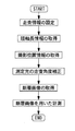
図4は眼軸長に応じて光スキャナの動作を変更し、断層画像を計測するまでの流れの一例を示すフローチャートである。眼底Efに対する走査情報(例えば、パターン、角度、速度)が設定されると、制御部70は、眼Eの長さ情報を取得し、取得された長さ情報に基づいて測定光の走査情報を補正する。例えば、設定された撮像範囲にて断層画像が取得されるように走査角度を補正する。すなわち、走査角度が変更されると、眼底上での撮像範囲が変更されるので、眼の長さの違いによる撮像範囲のずれが補正されるように走査角度が補正される。
FIG. 4 is a flowchart showing an example of a flow from changing the operation of the optical scanner according to the axial length to measuring a tomographic image. When scanning information (for example, a pattern, an angle, and a speed) for the fundus oculi Ef is set, the
制御部70は、補正された走査情報に対応する駆動信号を光スキャナ102に出力し、光スキャナ102を動作させ、所望する断層画像を得る。この場合、断層画像は、動画として連続的に取得されてもよいし、静止画として取得されてもよい。
The
測定光の走査情報(例えば、パターン、角度、速度)と、光スキャナ102に出力する駆動信号(例えば、パターン、範囲、速度)とは、予め対応付けられ、メモリ75に記憶されている。
Scanning information (for example, pattern, angle, speed) of measurement light and a drive signal (for example, pattern, range, speed) output to the
また、眼の長さの違いによる撮像範囲のずれの他に、異なる撮影位置において、一定の走査角度にて断層画像を撮影する場合でも、スキャン長にずれが生じる。例えば、光軸上の走査と、光軸から離れた周辺部での走査とを比較した場合、スキャン長が異なる。すなわち、一定の走査角度にて断層画像を取得しても、走査位置に応じて実際のスキャン長が変化する。 Further, in addition to the shift of the imaging range due to the difference in eye length, even when tomographic images are captured at different scanning positions and at a constant scanning angle, the scanning length is shifted. For example, when a scan on the optical axis is compared with a scan at a peripheral portion away from the optical axis, the scan length is different. That is, even if a tomographic image is acquired at a constant scanning angle, the actual scan length changes according to the scanning position.
そこで、測定光の走査位置情報を取得し、走査位置情報に基づいて、測定光の走査情報を補正することにより、断層画像におけるスキャン長のずれを補正する。例えば、制御部70は、眼球光学系の収差による断層画像のスキャン長のずれが補正されるように、走査角度を補正する。
Accordingly, the scan position information of the measurement light is acquired, and the scan information of the measurement light is corrected based on the scan position information, thereby correcting the scan length deviation in the tomographic image. For example, the
図5は、同じ走査角度において撮影した場合に、撮影位置(走査位置)に応じてスキャン長が異なることについて説明する図である。図5(a)は、Y方向に関して眼底上の異なる撮影位置において同じ走査角度にて断層画像を撮影した場合の図である。図5(b)は、図5(a)のような同じ走査角度での撮影であっても、各断層像のスキャン長tがY方向に関して異なることを示す図である。図5(b)の場合、実際のスキャン長がたる型に歪んでいる。 FIG. 5 is a diagram for explaining that the scan length differs according to the photographing position (scanning position) when photographing is performed at the same scanning angle. FIG. 5A is a diagram when tomographic images are captured at the same scanning angle at different imaging positions on the fundus in the Y direction. FIG. 5B is a diagram showing that the scan length t of each tomographic image is different with respect to the Y direction even when photographing is performed at the same scanning angle as in FIG. In the case of FIG. 5B, the actual scan length is distorted into a barrel shape.
例えば、光軸上でのスキャン長とその周辺部でのスキャン長とでは、光軸上でのスキャン長に対して周辺部のスキャン長は小さくなる。そして、実際の断層画像上では、同じ走査角度で撮影をすると、光軸上と周辺部で、スキャン長に差が生じるため、断層画像に歪みが生じる。これは、光学系の配置による収差がある場合と眼底の曲面形状が原因である。そのため、撮影位置に関わらず一定のスキャン長の断層像を得るには、スキャン長tを撮影位置に応じて補正する必要がある。 For example, the scan length on the optical axis and the scan length on the periphery thereof are smaller than the scan length on the optical axis. Then, on an actual tomographic image, when photographing is performed at the same scanning angle, a difference occurs in the scanning length on the optical axis and in the peripheral portion, so that the tomographic image is distorted. This is because there is an aberration due to the arrangement of the optical system and the curved shape of the fundus. Therefore, in order to obtain a tomographic image having a constant scan length regardless of the shooting position, it is necessary to correct the scan length t according to the shooting position.
ここで、眼底上におけるスキャン長t上の点を二次元座標系(x、y)で表すと、例えば、スキャン長にずれが生じているスキャン長上の点(画素)P1(x1、y1)、P2(x2、y2)は、本来、歪みがなければ、それぞれ点P1'(x1'、y1')、P2'(x2'、y2')に存在する(図5(b)参照)。 Here, when the point on the fundus on the scan length t is represented by the two-dimensional coordinate system (x, y), for example, the point (pixel) P1 (x1, y1) on the scan length where the scan length is deviated. , P2 (x2, y2) originally exist at points P1 ′ (x1 ′, y1 ′) and P2 ′ (x2 ′, y2 ′), respectively, without distortion (see FIG. 5B).
従って、スキャン長のずれを補正するために、スキャン長にずれが生じているスキャン長上における点Pnをスキャン長にずれが生じていないとしたときのスキャン長上における点Pn'に補正する。 Therefore, in order to correct the shift in the scan length, the point Pn on the scan length where the scan length is shifted is corrected to the point Pn ′ on the scan length when the scan length is not shifted.
スキャン長のずれ補正のための走査角度の補正量は、シミュレーション又は実験等によって算出される。そして、各撮影位置におけるスキャン長の全ての点Pnを本来存在すべき点Pn'に補正できるような、走査角度に補正して走査することで、スキャン長のずれを補正し、実際の断層画像の歪みを補正する。 The scan angle correction amount for correcting the scan length deviation is calculated by simulation or experiment. Then, scanning is performed by correcting the scanning angle so that all the points Pn of the scanning length at each photographing position can be corrected to the point Pn ′ that should exist, thereby correcting the deviation of the scanning length, and the actual tomographic image. Correct distortion.
そして、異なる撮影位置においても同じスキャン長に補正するために、走査角度の補正量が算出される。本実施例においては、予め、各々の長さの眼Eに対して、走査可能範囲の全ての画素に対応する走査角度の補正量をそれぞれ算出し、歪み補正データテーブルとしてメモリ75に記憶させておく。
Then, the correction amount of the scanning angle is calculated in order to correct the same scanning length even at different photographing positions. In this embodiment, for each eye E of each length, the scanning angle correction amounts corresponding to all the pixels in the scannable range are calculated in advance and stored in the
そして、制御部70が断層画像を撮影する際に、眼Eの長さ及び撮影位置に対して、メモリ75に記憶された歪み補正データテーブルを参照し、各撮影位置におけるスキャン長の全ての点Pnを本来存在すべき点Pn'に補正できるように走査角度を補正する。これにより、実際の断層画像の歪みが補正される。
Then, when the
以下の本装置の動作について説明する。制御部70は、被検者眼の長さ情報と走査位置情報を取得し、取得された長さ情報と走査位置に基づいて,各走査位置における眼底画像のスキャン長のずれを補正する。
The operation of this apparatus will be described below. The
<測定光の走査情報の設定>
正面画像を得る場合、例えば、縦横方向における撮像範囲tがそれぞれ設定され、ある領域内において測定光が二次元的に走査される(例えば、8mm×8mmなどのある矩形領域内において測定光がラスター走査される)。
<Setting of scanning information of measurement light>
When obtaining a front image, for example, an imaging range t in the vertical and horizontal directions is set, and the measurement light is scanned two-dimensionally within a certain area (for example, the measurement light is rastered within a certain rectangular area such as 8 mm × 8 mm). Scanned).
断層画像を得る場合、例えば、走査パターンと撮像範囲tが設定される。走査パターンについて、例えば、ラインスキャン、十字クロス、ラジアルスキャン、サークルスキャンから選択される。また、ある領域内において測定光が二次元的に走査されるようにしてもよい(例えば、5mm×5mmなどのある矩形領域内において測定光がラスター走査される)。 When obtaining a tomographic image, for example, a scanning pattern and an imaging range t are set. The scan pattern is selected from, for example, line scan, crosshair cross, radial scan, and circle scan. Further, the measurement light may be scanned two-dimensionally within a certain area (for example, the measurement light is raster-scanned within a certain rectangular area such as 5 mm × 5 mm).
また、断層画像の撮像範囲t1に合わせて、例えば、眼底スキャン長が設定される。例えば、複数のスキャン長(例えば、3mm、6mm、9mm)からあるスキャン長が選択される、又は数字入力により任意のスキャン長が選択される。眼底スキャン長について、ライン状のスキャンの場合、例えば、眼底上の走査開始位置から走査終了位置までの距離で表される。サークル状のスキャンの場合、例えば、円の直径で表される。矩形状のスキャンの場合、例えば、縦方向の走査距離と横方向の走査距離で表される。 Further, for example, a fundus scan length is set in accordance with the imaging range t1 of the tomographic image. For example, a certain scan length is selected from a plurality of scan lengths (for example, 3 mm, 6 mm, and 9 mm), or an arbitrary scan length is selected by numerical input. In the case of a line scan, the fundus scan length is represented, for example, by the distance from the scan start position on the fundus to the scan end position. In the case of a circular scan, for example, it is represented by a circle diameter. In the case of a rectangular scan, for example, it is represented by a vertical scanning distance and a horizontal scanning distance.
上記走査情報は、検者によって任意に設定されてもよいし、予め設定されていてもよい。また、走査情報として、眼底に対するある撮像範囲を基準とする倍率が設定されるようにしてもよい。すなわち、眼底に対する撮像範囲が設定されると、制御部70は、設定された撮像範囲にて断層画像が取得されるように走査情報を補正する。
The scanning information may be set arbitrarily by the examiner or may be set in advance. Further, as the scanning information, a magnification based on a certain imaging range with respect to the fundus may be set. That is, when the imaging range for the fundus is set, the
<眼軸長Xの取得>
眼軸長Xは、眼軸長測定装置(光干渉式、超音波式など)により測定される。例えば、本装置と測定装置110が通信回線で接続され、データ転送により眼軸長値が入力される。また、眼軸長について、操作部からの手入力により取得されてもよいし、測定値が記憶されたサーバーから取得されてもよい。また、本装置100に測定装置が設けられ、事前に測定が行われてもよい。例えば、光路長の調整を経て、眼底に対応する干渉信号が取得されるときの光路長変更用光学部材の位置情報から眼軸長が簡易的に求められてもよい。また、眼Eの視度、角膜曲率、水晶体パワーに基づいて補完的に眼軸長が求められてもよい。
<Acquisition of axial length X>
The axial length X is measured by an axial length measuring device (such as an optical interference type or an ultrasonic type). For example, the present apparatus and the measuring
<走査角度の補正値の算出>
断層画像を取得する際において、光学系に収差がある場合や眼球光学系の収差、眼底が曲面形状であることによって、断層画像に歪みが生じる。図6に示すように、眼底上の光軸上(図6のA位置)において、撮像範囲t1を撮影するために眼軸長Xに基づいて、走査角度Uが補正され、スキャン長SL1が設定され、撮影が行われる。そして、光軸上の周辺部(例えば、図6のB位置)において、光軸上の場合と同じの撮像範囲t1を撮影するために、同じの走査角度を用いて撮影を行うと、周辺部では、スキャン長SL1が小さくなり、スキャン長SL2となってしまう。そのため、撮像範囲t1が小さくなり、取得された断層画像に歪みが生じてしまう。
<Calculation of scan angle correction value>
When acquiring a tomographic image, distortion occurs in the tomographic image due to aberrations in the optical system, aberrations of the eyeball optical system, and the fundus having a curved surface. As shown in FIG. 6, on the optical axis on the fundus (position A in FIG. 6), the scanning angle U is corrected and the scan length SL1 is set based on the axial length X in order to capture the imaging range t1. And shooting is performed. Then, in the peripheral portion on the optical axis (for example, position B in FIG. 6), in order to photograph the same imaging range t1 as in the case of the optical axis, when photographing is performed using the same scanning angle, the peripheral portion Then, the scan length SL1 becomes small and becomes the scan length SL2. For this reason, the imaging range t1 is reduced, and the acquired tomographic image is distorted.
図7は眼軸長Xに対応する走査角度を求める際の一例を示す概略説明図であり、設定されたスキャン長SLと眼軸長Xに基づいて眼底Eに対する走査角度Uが算出される。 FIG. 7 is a schematic explanatory view showing an example of obtaining a scanning angle corresponding to the axial length X, and the scanning angle U with respect to the fundus E is calculated based on the set scanning length SL and the axial length X.
眼軸長X1(例えば、日本人の平均的な眼軸長値24mm)の眼E1の場合、走査角度U1にて光が走査されると、撮像範囲tの断層画像が取得される。走査角度U1及びスキャン長SLは、例えば、眼軸長X1を既知とするキャリブレーション用光学部材(例えば、模型眼)に対し、本装置の光学系における走査画角と撮像範囲との関係を求めることにより決定される(光線追跡法を用いたシミュレーションでも良い)。 In the case of an eye E1 having an axial length X1 (for example, an average axial length value of Japanese of 24 mm), a tomographic image of the imaging range t is acquired when light is scanned at a scanning angle U1. The scan angle U1 and the scan length SL are obtained, for example, for a calibration optical member (for example, a model eye) whose eye axis length X1 is known, and the relationship between the scan field angle and the imaging range in the optical system of the present apparatus. (It may be a simulation using a ray tracing method).
図7(a)において、撮影位置が光軸上の場合には、眼軸長X1の眼に対して、走査画角U1、スキャン長SLにて測定光が走査されると光軸上の撮像範囲t1が撮影される。なお、上記で説明したように、光軸周辺部の場合には、光軸上と同じ撮像範囲t1を撮影するのにスキャン長を長く補正する必要があり、スキャン長SL+ΔSLとする必要がある。設定されたスキャン長SLに対しΔSL分スキャン長が大きくなる。 In FIG. 7A, when the photographing position is on the optical axis, when the measurement light is scanned at the scanning angle of view U1 and the scanning length SL with respect to the eye having the axial length X1, imaging on the optical axis is performed. A range t1 is photographed. As described above, in the case of the peripheral portion of the optical axis, it is necessary to correct the scan length to be long in order to capture the same imaging range t1 as on the optical axis, and it is necessary to set the scan length SL + ΔSL. The scan length is increased by ΔSL with respect to the set scan length SL.
図7(b)は補正後の走査角度について概念図である。図6(a)と同じの撮像範囲t1を光軸周辺部で撮影する場合には、スキャン長SLに対する増加分ΔSLを加えるため、走査画角U1にΔUが加算され、走査画角U2(U2=U1+ΔU)に補正される。補正量ΔUは、ΔSL=qΔUの関係式(q:眼軸長及び撮影位置によって変化する係数)及び歪み補正データテーブルから求めることができる。ΔUは眼軸長X1に対するずれ量及び撮影位置に応じて増減される。 FIG. 7B is a conceptual diagram of the corrected scanning angle. When the same imaging range t1 as in FIG. 6A is photographed at the optical axis periphery, ΔU is added to the scanning field angle U1 to add an increase ΔSL to the scanning length SL, and the scanning field angle U2 (U2) = U1 + ΔU). The correction amount ΔU can be obtained from a relational expression of ΔSL = qΔU (q: a coefficient that varies depending on the axial length and the photographing position) and a distortion correction data table. ΔU is increased or decreased according to the shift amount with respect to the axial length X1 and the photographing position.
すなわち、本実施例のように、断層画像の歪みを補正する場合には、眼軸長X1が設定された眼Eに関して補正が行われるため、撮影位置に応じてΔUが増減されることになる。このような演算は、眼底上で走査される測定光への光線追跡をベースに行われる。なお、眼の光学的なデータは、例えば、模型眼などの値が用いられる。 That is, as in the present embodiment, when correcting the distortion of the tomographic image, correction is performed for the eye E for which the axial length X1 is set, and therefore ΔU is increased or decreased according to the photographing position. . Such calculation is performed based on ray tracing to the measurement light scanned on the fundus. For the optical data of the eyes, values such as model eyes are used, for example.
<補正走査角度を用いた眼底画像の取得>
そして、制御部70は、所定のフレームレートにおいて眼底Efに対し走査画角U2にて光が走査されるように、光スキャナ102を動作させ、測定光の進行方向を制御する。そして、制御部70は、その反射光を含む光を受光素子104にて受光し、受光素子104から出力される受光信号に基づいて断層画像を取得する。
<Acquisition of fundus image using corrected scanning angle>
Then, the
以上のように、測定光の走査情報が撮影位置に応じて補正されることにより、実際の断層画像の歪みが補正される。すなわち、走査角度を補正して同じ走査速度/フレームレートにて画像を取得することにより、所望のスキャン長にて測定点の数が同じ画像が得られる。これにより、異なる撮影位置にて断層画像の取得が行われても、一定の撮像範囲にて断層画像が取得される。これにより、断層画像に対して定量計測を行う際の計測精度が高まる。 As described above, the distortion of the actual tomographic image is corrected by correcting the scanning information of the measurement light according to the imaging position. That is, by correcting the scanning angle and acquiring images at the same scanning speed / frame rate, an image with the same number of measurement points can be obtained with a desired scanning length. As a result, even if tomographic images are acquired at different imaging positions, the tomographic images are acquired within a certain imaging range. Thereby, the measurement accuracy at the time of performing quantitative measurement with respect to a tomographic image increases.
なお、上記説明においては、ある走査方向を例にとって説明したが、複数の走査方向に関して断層画像をそれぞれ取得する場合、制御部70は、各走査方向に関して走査位置情報を取得し、それぞれ走査角度を補正する。又、測定光を眼底上で二次元的に走査することにより3次元断層画像を得る場合、制御部70は、二次元的な撮像範囲に対応する3次元断層画像が取得できるように、走査情報を補正してもよい。
In the above description, a certain scanning direction has been described as an example. However, when acquiring tomographic images with respect to a plurality of scanning directions, the
また、正面像撮像光学系を用いて正面画像を得る場合、制御部70は、縦横の走査方向に関して走査位置情報を得て、それぞれ走査角度を補正する。
Further, when a front image is obtained using the front image capturing optical system, the
<実距離計測>
取得された眼底画像は、メモリ72に記憶され、モニタ75上に表示される。そして、制御部70は、断層画像Gtと正面画像Gfから任意に選択される少なくともいずれかの眼底画像を用いて眼底上の2点間の実距離を測定する演算処理を行う。
<Real distance measurement>
The acquired fundus image is stored in the
画像上の任意の2点(図2の点A及び点B参照)がマウス74a等の操作(例えば、クリック)を介して特定されたとき、制御部70は、指定された2点間の距離を眼底の実距離に換算する。また、画像に対して移動表示される2つのマーカー(指標)間の距離を制御部70が眼底の実距離に換算してもよい。
When any two points on the image (see point A and point B in FIG. 2) are specified through an operation (for example, click) of the
この場合、眼底画像のスキャン長は一定であるから、各種計測において一定の計測精度が保たれる。したがって、より定量的な解析/分析が可能となる。 In this case, since the scan length of the fundus image is constant, constant measurement accuracy is maintained in various measurements. Therefore, more quantitative analysis / analysis is possible.
なお、実距離測定のために任意の2点間を指定する手法としては、種々の変容が可能であり、上記手法に限るものはない。例えば、サークル状のマーカを用いて中心からの距離又は直径を求めるようにしてもよい。また、上記2点間の距離に、深さ方向を含めた3点以上の点に基づき形状/面積が計測されてもよい。もちろん、3次元画像のXY方向に関する計測が行われてもよい(例えば、層厚マップ上における計測)。また、断層像中のある部分が画像処理により検出されることにより、計測部分が特定されてもよい。 In addition, as a method for designating an arbitrary two points for the actual distance measurement, various modifications are possible, and the method is not limited to the above method. For example, the distance or diameter from the center may be obtained using a circle-shaped marker. Further, the shape / area may be measured based on the distance between the two points based on three or more points including the depth direction. Of course, measurement in the XY direction of the three-dimensional image may be performed (for example, measurement on a layer thickness map). Further, the measurement portion may be specified by detecting a certain portion in the tomographic image by image processing.
眼軸長Xに対応する走査画角Uの補正について、制御部70は、所定の演算式により求めてもよいし、眼軸長Xと走査画角Uとを関係付けたテーブルから求めてもよい。また、走査画角Uは光スキャナ102の駆動信号により制御されるから、眼軸長Xと光スキャナ102の駆動信号とが関連付けられたものであってもよい。また、眼軸長情報は、実際の測定値でなくとも、眼軸長に関連付けられた情報であればよく、眼軸長測定装置における光路長変更部材の位置情報であってもよい。上記補正を行う場合、ソフトウェアにより走査情報が補正されても良いし、専用の駆動回路(例えば、LSI)等のハードウェアにより走査情報が補正されてもよい。
Regarding the correction of the scanning angle of view U corresponding to the axial length X, the
また、走査角度を一定とし、所定のフレームレートにおける測定光の走査速度が眼軸長に応じて補正されてもよい。また、走査速度を一定とし、眼底画像を得るフレームレートを眼軸長に応じて変化させるようにしてもよい。また、光源101の点灯タイミングの変更により撮像範囲が補正されるようにしてもよい。これらの手法によれば、光走査による撮像範囲が結果的に補正される。
Alternatively, the scanning angle may be fixed, and the scanning speed of the measurement light at a predetermined frame rate may be corrected according to the axial length. Alternatively, the scanning speed may be constant, and the frame rate for obtaining the fundus image may be changed according to the axial length. Further, the imaging range may be corrected by changing the lighting timing of the
また、眼Eの角膜形状/眼屈折力(視度)の少なくともいずれかを取得し、取得された角膜形状/眼屈折力に基づいて走査画角が補正されるようにしてもよい。この場合、角膜曲率半径が小さい(眼屈折力が強い)ほど、測定光が屈折され、撮像範囲が大きくなる。そこで、例えば、角膜曲率半径、眼屈折力に応じて、眼底上の撮像範囲が所定の撮像範囲になるように走査角度が補正される。この場合、ΔSL=qΔUの関係式について、qには、角膜形状/眼屈折力によって変化する係数が用いられる。なお、角膜形状/眼屈折力を得る場合、上記眼軸長同様に、本装置に設けられても良いし、他の装置から取得されるようにしてもよい。この場合、さらに、視度情報/角膜形状情報の少なくともいずれかと眼の長さ情報に基づいて走査情報が補正されるようにしてもよい。 Further, at least one of the corneal shape / eye refractive power (diopter) of the eye E may be acquired, and the scanning angle of view may be corrected based on the acquired corneal shape / eye refractive power. In this case, the smaller the corneal curvature radius (the stronger the eye refractive power), the more the measurement light is refracted and the imaging range becomes larger. Therefore, for example, the scanning angle is corrected so that the imaging range on the fundus becomes a predetermined imaging range in accordance with the corneal curvature radius and the eye refractive power. In this case, in the relational expression of ΔSL = qΔU, a coefficient that varies depending on the corneal shape / eye refractive power is used for q. In addition, when obtaining corneal shape / eye refractive power, it may be provided in this apparatus like the said axial length, and may be acquired from another apparatus. In this case, the scanning information may be further corrected based on at least one of diopter information / corneal shape information and eye length information.
なお、以上の説明においては、眼底を例にとって説明したが、走査型撮像光学系と被検物との距離が変化する可能性があれば、本発明が利用されうる。この場合、例えば、被検物の位置情報を取得し、取得された位置情報に基づいて測定光の走査情報(例えば、走査角度)を補正すればよい。被検物の位置情報は、例えば、光路長可変用光学部材の位置情報から取得される。また、被検物と装置との距離を測定可能なセンサからの出力信号、検者の手入力などから取得されるようにしてもよい。 In the above description, the fundus is taken as an example, but the present invention can be used if there is a possibility that the distance between the scanning imaging optical system and the test object may change. In this case, for example, the position information of the test object is acquired, and the scanning information (for example, the scanning angle) of the measurement light may be corrected based on the acquired position information. The position information of the test object is acquired from the position information of the optical member for changing the optical path length, for example. Moreover, you may make it acquire from the output signal from the sensor which can measure the distance of a to-be-tested object and an apparatus, the examiner's manual input, etc.
上記のようにして測定光の走査情報が被検物までの距離に応じて補正されることにより、所望の撮像範囲で画像が取得される。なお、測定対象としては、例えば、前眼部、皮膚、内臓などの生体、生体以外の試料などが考えられる。 As described above, the scanning information of the measurement light is corrected according to the distance to the test object, whereby an image is acquired in a desired imaging range. In addition, as a measuring object, biological samples, such as an anterior eye part, skin, and internal organs, samples other than a biological body, etc. are considered, for example.
なお、上記説明においては、光軸に対する撮影位置に応じて測定光の走査角度を補正したがこれに限定されない。制御部70は、光スキャナ102によって走査される測定光の走査位置情報を取得し、取得された走査位置情報に基づいて,各走査位置における眼底画像のスキャン長のずれを補正すればよい。例えば、他の手法として、制御部70は、断層画像の取得後、取得された断層画像の撮影位置に応じて、測定光のスキャン方向(図2)に関して、断層画像を画像処理により伸縮させるようにしてもよい。すなわち、制御部70は、このような手法であっても、各走査位置での断層画像のスキャン長が一定となる。
In the above description, the scanning angle of the measurement light is corrected according to the photographing position with respect to the optical axis, but the present invention is not limited to this. The
なお、光軸から離れた位置での撮像範囲が狭くなることを鑑み、制御部70は、画像解析に必要な撮像範囲よりも広いスキャン長にて断層画像を取得し、必要な撮像範囲に対応する断層画像の伸縮率を調整するようにしてもよい。
In view of the fact that the imaging range at a position away from the optical axis becomes narrow, the
70 制御部
72 メモリ
74 操作部
75 モニタ
100 撮像光学系
101 光源
102 光スキャナ
110 眼距離測定装置
DESCRIPTION OF
Claims (3)
前記光走査手段によって走査される測定光の走査位置情報を取得するとともに、前記眼底撮影光学系と被検者眼底との距離を取得し、取得された前記走査位置情報及び前記距離に基づいて,各走査位置における眼底画像のスキャン長のずれを補正する補正手段と、
を備えることを特徴とする眼底撮影装置。 In order to obtain a fundus image, comprising: an optical scanning unit that scans at least part of light emitted from the light source on the fundus of the subject's eye as measurement light; and a light receiving unit that receives light including the reflected light. The fundus imaging optical system of
Obtains the scanning position information of the scanned measurement light by the optical scanning means, said obtains the distance between the fundus photographing optical system and the subject eye fundus, based on the acquired scan position information and the distance, Correction means for correcting a shift in scan length of the fundus image at each scanning position;
A fundus photographing apparatus comprising:
Priority Applications (1)
| Application Number | Priority Date | Filing Date | Title |
|---|---|---|---|
| JP2010269810A JP5735789B2 (en) | 2010-12-02 | 2010-12-02 | Fundus photographing device |
Applications Claiming Priority (1)
| Application Number | Priority Date | Filing Date | Title |
|---|---|---|---|
| JP2010269810A JP5735789B2 (en) | 2010-12-02 | 2010-12-02 | Fundus photographing device |
Publications (3)
| Publication Number | Publication Date |
|---|---|
| JP2012115575A JP2012115575A (en) | 2012-06-21 |
| JP2012115575A5 JP2012115575A5 (en) | 2014-01-16 |
| JP5735789B2 true JP5735789B2 (en) | 2015-06-17 |
Family
ID=46499158
Family Applications (1)
| Application Number | Title | Priority Date | Filing Date |
|---|---|---|---|
| JP2010269810A Active JP5735789B2 (en) | 2010-12-02 | 2010-12-02 | Fundus photographing device |
Country Status (1)
| Country | Link |
|---|---|
| JP (1) | JP5735789B2 (en) |
Families Citing this family (9)
| Publication number | Priority date | Publication date | Assignee | Title |
|---|---|---|---|---|
| GB2509131B (en) * | 2012-12-21 | 2017-05-17 | Optos Plc | Improvements in and relating to ophthalmoscopes |
| WO2016039188A1 (en) * | 2014-09-08 | 2016-03-17 | 国立大学法人東北大学 | Ocular fundus analyzing device and ocular fundus observation device |
| JP5937163B2 (en) | 2014-07-23 | 2016-06-22 | 国立大学法人東北大学 | Fundus analysis apparatus and fundus observation apparatus |
| JP2019058491A (en) * | 2017-09-27 | 2019-04-18 | 株式会社トプコン | Ophthalmological device |
| JP2019154996A (en) | 2018-03-16 | 2019-09-19 | 株式会社トプコン | Ophthalmologic apparatus and ophthalmologic information processing apparatus |
| JP7480553B2 (en) | 2020-03-30 | 2024-05-10 | 株式会社ニデック | Ophthalmic Equipment |
| JP7480552B2 (en) | 2020-03-30 | 2024-05-10 | 株式会社ニデック | Ophthalmic device and axial length calculation program |
| JP7447619B2 (en) | 2020-03-30 | 2024-03-12 | 株式会社ニデック | ophthalmology equipment |
| EP4276404A1 (en) | 2022-05-13 | 2023-11-15 | Optos PLC | Non-confocal point-scan fourier-domain optical coherence tomography imaging system |
Family Cites Families (5)
| Publication number | Priority date | Publication date | Assignee | Title |
|---|---|---|---|---|
| JP3369623B2 (en) * | 1993-03-16 | 2003-01-20 | 興和株式会社 | Laser scanning ophthalmic imaging device |
| JP4822969B2 (en) * | 2006-07-27 | 2011-11-24 | 株式会社ニデック | Ophthalmic imaging equipment |
| GB0622325D0 (en) * | 2006-11-09 | 2006-12-20 | Optos Plc | Improvements in or relating to retinal scanning |
| JP4921201B2 (en) * | 2007-02-23 | 2012-04-25 | 株式会社トプコン | Optical image measurement device and program for controlling optical image measurement device |
| JP5324839B2 (en) * | 2008-06-19 | 2013-10-23 | 株式会社トプコン | Optical image measuring device |
-
2010
- 2010-12-02 JP JP2010269810A patent/JP5735789B2/en active Active
Also Published As
| Publication number | Publication date |
|---|---|
| JP2012115575A (en) | 2012-06-21 |
Similar Documents
| Publication | Publication Date | Title |
|---|---|---|
| JP5735789B2 (en) | Fundus photographing device | |
| JP5601613B2 (en) | Fundus photographing device | |
| JP5685013B2 (en) | Optical tomographic imaging apparatus, control method therefor, and program | |
| JP5635898B2 (en) | Fundus imaging apparatus and control method thereof | |
| US8939580B2 (en) | Characteristic image extraction method and ophthalmologic apparatus | |
| JP5297415B2 (en) | Ophthalmic device and ophthalmic method | |
| JP2014140491A (en) | Ophthalmology imaging apparatus | |
| JP2015104554A (en) | Ophthalmologic measuring device and ophthalmologic measuring program | |
| US10123699B2 (en) | Ophthalmologic apparatus and imaging method | |
| JP7368581B2 (en) | Ophthalmology equipment and ophthalmology information processing equipment | |
| JP7164679B2 (en) | Ophthalmic device and its control method | |
| US10674902B2 (en) | Information processing apparatus, operation method thereof, and computer program | |
| JP2011110290A (en) | Fundus imaging apparatus | |
| JP7367433B2 (en) | Ophthalmology imaging device | |
| JP2019005254A (en) | Ophthalmologic apparatus and control method of the same | |
| JP6558161B2 (en) | Ophthalmic apparatus and image processing program | |
| JP2015531275A (en) | Method for realizing OCT imaging and other imaging of the eye | |
| JP2019054974A (en) | Ophthalmologic apparatus | |
| JP6662412B2 (en) | Ophthalmic measurement device | |
| JP5891001B2 (en) | Tomographic apparatus and tomographic image correction processing method | |
| JP2012010798A (en) | Ophthalmologic device | |
| JP2023019698A (en) | Ophthalmologic examination device and control method of ophthalmologic examination device | |
| JP2019208857A (en) | Oct apparatus | |
| JP2022129243A (en) | Ophthalmologic apparatus, control method of ophthalmologic apparatus, and program | |
| JP2013144236A (en) | Ophthalmic apparatus and ophthalmic method |
Legal Events
| Date | Code | Title | Description |
|---|---|---|---|
| A521 | Request for written amendment filed |
Free format text: JAPANESE INTERMEDIATE CODE: A523 Effective date: 20131125 |
|
| A621 | Written request for application examination |
Free format text: JAPANESE INTERMEDIATE CODE: A621 Effective date: 20131125 |
|
| A977 | Report on retrieval |
Free format text: JAPANESE INTERMEDIATE CODE: A971007 Effective date: 20140729 |
|
| A131 | Notification of reasons for refusal |
Free format text: JAPANESE INTERMEDIATE CODE: A131 Effective date: 20140819 |
|
| TRDD | Decision of grant or rejection written | ||
| A01 | Written decision to grant a patent or to grant a registration (utility model) |
Free format text: JAPANESE INTERMEDIATE CODE: A01 Effective date: 20150318 |
|
| A61 | First payment of annual fees (during grant procedure) |
Free format text: JAPANESE INTERMEDIATE CODE: A61 Effective date: 20150417 |
|
| R150 | Certificate of patent or registration of utility model |
Ref document number: 5735789 Country of ref document: JP Free format text: JAPANESE INTERMEDIATE CODE: R150 |
|
| R250 | Receipt of annual fees |
Free format text: JAPANESE INTERMEDIATE CODE: R250 |
|
| R250 | Receipt of annual fees |
Free format text: JAPANESE INTERMEDIATE CODE: R250 |
|
| R250 | Receipt of annual fees |
Free format text: JAPANESE INTERMEDIATE CODE: R250 |
|
| R250 | Receipt of annual fees |
Free format text: JAPANESE INTERMEDIATE CODE: R250 |
|
| R250 | Receipt of annual fees |
Free format text: JAPANESE INTERMEDIATE CODE: R250 |
|
| R250 | Receipt of annual fees |
Free format text: JAPANESE INTERMEDIATE CODE: R250 |
|
| R250 | Receipt of annual fees |
Free format text: JAPANESE INTERMEDIATE CODE: R250 |