JP5732936B2 - Transmitting station, receiving station, communication system, and gap allocation method - Google Patents
Transmitting station, receiving station, communication system, and gap allocation method Download PDFInfo
- Publication number
- JP5732936B2 JP5732936B2 JP2011057287A JP2011057287A JP5732936B2 JP 5732936 B2 JP5732936 B2 JP 5732936B2 JP 2011057287 A JP2011057287 A JP 2011057287A JP 2011057287 A JP2011057287 A JP 2011057287A JP 5732936 B2 JP5732936 B2 JP 5732936B2
- Authority
- JP
- Japan
- Prior art keywords
- gap
- reception quality
- unit
- radio
- radio carrier
- Prior art date
- Legal status (The legal status is an assumption and is not a legal conclusion. Google has not performed a legal analysis and makes no representation as to the accuracy of the status listed.)
- Expired - Fee Related
Links
Images


Classifications
-
- H—ELECTRICITY
- H04—ELECTRIC COMMUNICATION TECHNIQUE
- H04L—TRANSMISSION OF DIGITAL INFORMATION, e.g. TELEGRAPHIC COMMUNICATION
- H04L27/00—Modulated-carrier systems
- H04L27/26—Systems using multi-frequency codes
- H04L27/2601—Multicarrier modulation systems
- H04L27/2602—Signal structure
- H04L27/2605—Symbol extensions, e.g. Zero Tail, Unique Word [UW]
-
- H—ELECTRICITY
- H04—ELECTRIC COMMUNICATION TECHNIQUE
- H04L—TRANSMISSION OF DIGITAL INFORMATION, e.g. TELEGRAPHIC COMMUNICATION
- H04L5/00—Arrangements affording multiple use of the transmission path
- H04L5/0001—Arrangements for dividing the transmission path
- H04L5/0003—Two-dimensional division
- H04L5/0005—Time-frequency
- H04L5/0007—Time-frequency the frequencies being orthogonal, e.g. OFDM(A), DMT
- H04L5/001—Time-frequency the frequencies being orthogonal, e.g. OFDM(A), DMT the frequencies being arranged in component carriers
-
- H—ELECTRICITY
- H04—ELECTRIC COMMUNICATION TECHNIQUE
- H04W—WIRELESS COMMUNICATION NETWORKS
- H04W72/00—Local resource management
- H04W72/50—Allocation or scheduling criteria for wireless resources
- H04W72/54—Allocation or scheduling criteria for wireless resources based on quality criteria
- H04W72/542—Allocation or scheduling criteria for wireless resources based on quality criteria using measured or perceived quality
-
- H—ELECTRICITY
- H04—ELECTRIC COMMUNICATION TECHNIQUE
- H04W—WIRELESS COMMUNICATION NETWORKS
- H04W72/00—Local resource management
- H04W72/04—Wireless resource allocation
- H04W72/044—Wireless resource allocation based on the type of the allocated resource
- H04W72/0453—Resources in frequency domain, e.g. a carrier in FDMA
Description
本発明は、送信局、受信局、通信システムおよびギャップ割当方法に関する。 The present invention relates to a transmitting station, a receiving station, a communication system, and a gap allocation method.
標準化が進められているLTE−A(Long Term Evolution-Advanced)では、より大容量のデータを伝送可能な技術として、キャリアアグリゲーション(CA:Carrier Aggregation)を導入することが検討されている。CAでは、送信局である基地局と受信局である移動局とが、コンポーネントキャリア(CC:Component Carrier)と呼ばれる、周波数帯が異なる複数の無線キャリアを用いてデータの送受信を行う。 In LTE-A (Long Term Evolution-Advanced), which is being standardized, introduction of carrier aggregation (CA) as a technology capable of transmitting a larger amount of data is being studied. In CA, a base station, which is a transmitting station, and a mobile station, which is a receiving station, transmit and receive data using a plurality of radio carriers having different frequency bands, called component carriers (CC).
また、LTE−Aでは、CAによりデータの送受信を行う場合、送信局が、データの送信を停止する期間であるギャップ(measurement GAP(GAP))をCCごとに割り当てることが提案されている。GAPがCCごとに割り当てられると、受信局が、このGAPを各CCに設定し、設定したGAPにおいて周波数を切り替え、切り替え後の周波数の受信品質の測定などを行う。 In LTE-A, when transmitting and receiving data by CA, it is proposed that a transmission station allocates a gap (measurement GAP (GAP)), which is a period during which data transmission is stopped, for each CC. When the GAP is assigned to each CC, the receiving station sets this GAP to each CC, switches the frequency in the set GAP, and measures the reception quality of the frequency after switching.
しかしながら、GAPをCCごとに割り当てる従来技術では、データの伝送率が低下するという問題がある。 However, the conventional technique for assigning a GAP for each CC has a problem that the data transmission rate decreases.
具体的には、従来技術では、CCごとに割り当てられるGAPの周期や時間幅が予め定められており、送信局が、周期や時間幅が予め定められたGAPをCCごとに受信局側に割り当てる。そのため、例えば、無線環境の変化などに起因して受信局側の各CCの受信品質が異なる場合であっても、各CCに割り当てられたGAPの周期や時間幅は固定されている。これは、受信品質の悪いCCよりも受信品質の良いCCに対して所定時間当たりにより多くのGAPが割り当てられる可能性があることを意味する。その結果、受信品質の良いCCを用いたデータの伝送がGAPにより停滞し、データの伝送率が低下する。 Specifically, in the prior art, the GAP period and time width assigned to each CC are determined in advance, and the transmitting station assigns a GAP with a predetermined period and time width to the receiving station for each CC. . Therefore, for example, even if the reception quality of each CC on the receiving station side is different due to changes in the radio environment, the GAP period and time width assigned to each CC are fixed. This means that more GAPs may be allocated per predetermined time to CCs with better reception quality than CCs with poor reception quality. As a result, data transmission using CCs with good reception quality is stagnated by GAP, and the data transmission rate is reduced.
開示の技術は、上記に鑑みてなされたものであって、データの伝送率を向上させることができる送信局、受信局、通信システムおよびギャップ割当方法を提供することを目的とする。 The disclosed technique has been made in view of the above, and an object thereof is to provide a transmitting station, a receiving station, a communication system, and a gap allocation method capable of improving a data transmission rate.
本願の開示する送信局は、周波数帯が異なる複数の無線キャリアを用いて自装置とデータの送受信を行う受信局から報告される各前記無線キャリアの受信品質を取得し、取得した各前記無線キャリアの受信品質に応じて、前記データの送信の停止期間であるギャップを前記無線キャリアごとに割り当てるプロセッサを備えた。 The transmitting station disclosed in the present application acquires reception quality of each of the wireless carriers reported from a receiving station that transmits and receives data to and from its own device using a plurality of wireless carriers having different frequency bands, and acquires each of the acquired wireless carriers And a processor for allocating a gap, which is a period during which the data transmission is stopped, for each radio carrier in accordance with the reception quality.
本願の開示する送信局の一つの態様によれば、データの伝送率を向上させることができるという効果を奏する。 According to one aspect of the transmitting station disclosed in the present application, it is possible to improve the data transmission rate.
以下に、本願の開示する送信局、受信局、通信システムおよびギャップ割当方法の実施例を図面に基づいて詳細に説明する。なお、この実施例によりこの発明が限定されるものではない。 Hereinafter, embodiments of a transmitting station, a receiving station, a communication system, and a gap allocation method disclosed in the present application will be described in detail with reference to the drawings. Note that the present invention is not limited to the embodiments.
3GPP(3rd Generation Partnership Project)では、LTEの発展形として、LTE−Aの議論が行われている。LTE−Aでは、高速通信を実現するため、周波数帯が異なる複数の無線キャリアを集約しこの集約された帯域を使用してより大容量のデータを伝送する技術が導入される。これは、キャリアアグリゲーション(Carrier Aggregation(CA))と呼ばれている。 In 3GPP (3rd Generation Partnership Project), LTE-A is discussed as a development form of LTE. In LTE-A, in order to realize high-speed communication, a technique is introduced in which a plurality of radio carriers having different frequency bands are aggregated and a larger amount of data is transmitted using the aggregated band. This is called carrier aggregation (CA).
図1は、CAの一例を示す図である。図1において、集約される各無線キャリアをコンポーネントキャリア(Component Carrier(CC))と呼ぶ。CAでは、たとえば、送信局と受信局とが、複数のCCを用いてデータの送受信を行う。ここでは、一例として、帯域幅20MHzのCCを5個(CC#1〜CC#5)用いて通信を行う場合が示されている。なお、図1では、連続した周波数帯域のCCを用いて通信を行う場合を示しているが、CAでは、たとえば、図2に示すように、連続していない周波数帯域のCCを用いて通信を行うことも可能である。図2は、不連続なCCによるCAの一例を示す図である。
FIG. 1 is a diagram illustrating an example of CA. In FIG. 1, each radio carrier to be aggregated is referred to as a component carrier (Component Carrier (CC)). In CA, for example, a transmitting station and a receiving station transmit and receive data using a plurality of CCs. Here, as an example, a case where communication is performed using five CCs with a bandwidth of 20 MHz (
また、CAによりデータの送受信を行う通信システムでは、基地局が、データの送信を停止する期間であるギャップ(measurement GAP(GAP))をCCごとに割り当てる。 Further, in a communication system that transmits and receives data using CA, a base station allocates a gap (measurement GAP (GAP)), which is a period during which data transmission is stopped, for each CC.
図3は、CCごとに割り当てられたGAPの一例を示す図である。図3に示すように、CCごとにGAPが割り当てられると、受信局では、GAPを各CCに設定し、設定したGAPにおいて周波数を切り替え、切り替え後の周波数の受信品質の測定(Measurement)などを行う。ここでは、一例として、周波数が異なる2個のCC(CC#1、CC#2)を用いて通信を行う場合に、同一の周期および同一の時間幅を有する2つのGAPが各CCに割り当てられる例が示されている。なお、図3のようなGAPが割り当てられると、受信局では、GAPを各CCに設定し、各CCに設定したGAPにおいて周波数をf1およびf2からf3およびf4へそれぞれ切り替え、切り替え後の周波数の受信品質の測定(Measurement)を行う。
FIG. 3 is a diagram illustrating an example of a GAP assigned to each CC. As shown in FIG. 3, when a GAP is assigned to each CC, the receiving station sets the GAP to each CC, switches the frequency in the set GAP, and measures the measurement quality of the frequency after the switching (Measurement). Do. Here, as an example, when communication is performed using two CCs (
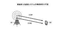
次に、CAによりデータの送受信を行う実施例1の通信システムについて説明する。図4は、実施例1の通信システムの構成例を示す図である。図4に示すように、通信システムは、基地局10と、移動機50とを有する。基地局10は、送信局の一例であり、移動機50は、受信局の一例である。基地局10と移動機50とは、周波数帯が異なる複数のCC(CC#1およびCC#2)を用いてデータの送受信を行う。基地局10は、CC#1およびCC#2へデータを送信する。移動機50は、携帯端末などであり、CC#1およびCC#2からのデータを受信する。また、基地局10は、GAPをCCごとに割り当てる。なお、図4では、基地局10と移動機50とが2つのCCを用いてデータの送受信を行う例を示しているが、これに限らず、例えば、3つ以上のCCを用いてデータの送受信を行うこととしてもよい。
Next, a communication system according to the first embodiment that transmits and receives data by CA will be described. FIG. 4 is a diagram illustrating a configuration example of a communication system according to the first embodiment. As shown in FIG. 4, the communication system includes a
ここで、本実施例1の通信システムに含まれる基地局10におけるギャップ割当方法を説明する前に、その前提となる従来のギャップ割当方法について説明する。
Here, before describing the gap allocation method in the
図5は、CAにおける従来のギャップ割当方法の一例を示す図である。図5に示した例では、無線環境の変化などに起因して受信局である移動機側の各CCの受信品質が異なる場合を示しており、CC#2の受信品質よりもCC#1の受信品質が悪いものとする。CAによりデータの送受信を行う従来の通信システムでは、CCごとに割り当てられるGAPの周期や時間幅が予め定められており、送信局である基地局が、周期や時間幅が予め定められたGAPをCCごとに割り当てる。そのため、図5に示した例のように、無線環境の変化などに起因して受信局である移動機側の各CCの受信品質が異なる場合であっても、各CCに割り当てられたGAPの周期や時間幅は、固定されたままである。したがって、受信品質の悪いCC#1よりも受信品質の良いCC#2に対して所定時間当たりにより多くのGAPが割り当てられる可能性がある。このように、受信品質の良いCCに対して多くのGAPが割り当てられた場合には、受信品質の良いCCを用いたデータの伝送がGAPにより停滞し、データの伝送率が低下する可能性がある。
FIG. 5 is a diagram illustrating an example of a conventional gap allocation method in CA. The example shown in FIG. 5 shows a case where the reception quality of each CC on the mobile station side, which is a receiving station, is different due to changes in the radio environment, and the
そこで、本実施例では、GAPの割り当てに関する処理を工夫することにより、上記図5に示したような問題を回避する。 Therefore, in this embodiment, the problem as shown in FIG. 5 is avoided by devising the process related to the GAP allocation.
次に、本実施例の通信システムに含まれる基地局10におけるギャップ割当方法について説明する。図6は、実施例1の通信システムに含まれる基地局10におけるギャップ割当方法について説明するための図である。図6に示した例では、図5に示した例と同様に、無線環境の変化などに起因して各CCの受信品質が異なる場合を示しており、CC#2の受信品質よりもCC#1の受信品質が悪いものとする。本実施例のギャップ割当方法では、基地局10は、まず、CC#1およびCC#2を用いて基地局10とデータの送受信を行う移動機50から報告される各CCの受信品質を取得する。そして、基地局10は、取得された各CCの受信品質に応じてGAPを各CCに割り当てる。ここでは、CC#2の受信品質よりもCC#1の受信品質が悪い。そのため、基地局10は、受信品質の良いCC#2よりも受信品質の悪いCC#1に対して所定時間当たりにより多くのGAPを割り当てる。図6に示す例では、基地局は、受信品質の良いCC#2に対して所定時間当たりに2つのGAPを割り当て、受信品質の悪いCC#1に対して所定時間当たりに4つのGAPを割り当てる。
Next, a gap allocation method in the
このように、本実施例におけるギャップ割当方法では、基地局10が、移動機50から報告される各CCの受信品質の受信品質に応じて、GAPを各CCに割り当てる。このため、本実施例におけるギャップ割当方法では、相対的に受信品質の良いCCよりも相対的に受信品質の悪いCCに対して優先的にGAPを割り当てることができる。これにより、受信品質の良いCCを用いてより多くのデータを伝送することができるので、無線通信ネットワークシステム全体としてのデータの伝送率を向上することができる。
As described above, in the gap allocation method in the present embodiment, the
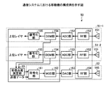
次に、図4に示した通信システムの構成について説明する。図7は、通信システムにおける基地局10の構成例を示す図である。図7に示すように、基地局10は、データ送信部11−1、11−2、データ受信部12およびGAP割当制御部13を有する。
Next, the configuration of the communication system shown in FIG. 4 will be described. FIG. 7 is a diagram illustrating a configuration example of the
データ送信部11−1、11−2は、それぞれ対応するCCへデータを送信する。データ送信部11−1、11−2は、それぞれ、データ生成部111、符号化部112、MOD(Modulator)部113、DAC(Digital to Analog Converter)部114、RF(Radio Frequency)部115およびアンテナ116を有する。データ生成部111は、後述するGAP割当制御部13によりCCごとに割り当てられたGAPを規定する割当情報を含めたデータを生成する。符号化部112は、生成されたデータに対して例えばTurbo符号のような誤り訂正符号を適用する。MOD部113は、QPSK(Quadrature Phase Shift Keying)や16QAM(Quadrature Amplitude Modulation)といった変調方式を用いて各CCのデータを個別に変調する。なお、OFDM(Orthogonal Frequency Division Multiplexing)伝送が行われる場合には、MOD部113は、周波数領域の信号を時間領域の信号に変換する逆高速フーリエ変換を行い、逆高速フーリエ変換後の信号にCP(cyclic prefix)を付加する。DAC部114は、デジタルの信号をアナログの信号に変換する。RF部115は、受け取った信号を無線周波数帯へアップコンバージョンする。アンテナ116は、アップコンバージョン後の信号を移動機50へ送信する。
The data transmission units 11-1 and 11-2 each transmit data to the corresponding CC. The data transmission units 11-1 and 11-2 include a
データ受信部12は、移動機50により送信されたデータを各CCから受信する。データ受信部12は、アンテナ121、RF部122、ADC(Analog to Digital Converter)部123、DEM(Demodulator)部124および復号化部125を有する。アンテナ121は、移動機50により送信された信号をCCごとに受信する。RF部122は、受け取った信号をベースバンド帯へダウンコンバージョンする。ADC部123は、アナログの信号をデジタルの信号に変換する。DEM部124は、QPSKや16QAMといった変調方式を用いて変調された信号から各CCのデータを個別に復調する。なお、OFDM伝送が行われる場合には、DEM部124は、受け取った信号からCPを除去し、時間領域の信号を周波数領域の信号に変換する高速フーリエ変換を行う。復号化部125は、受け取ったデータからTurbo符号のような誤り訂正符号を復号する。復号後のデータは、CCごとにGAP割当制御部13へ引き渡される。
The
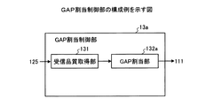
GAP割当制御部13は、移動機50からフィードバックされる情報に基づいて各CCに対するGAPの割り当てを制御する。図8は、GAP割当制御部13の構成例を示す図である。図8に示すように、GAP割当制御部13は、受信品質取得部131、GAP割当部132およびGAP記憶部133を有する。
The GAP
受信品質取得部131は、移動機50から報告される各CCの受信品質を取得する。具体的には、受信品質取得部131は、移動機50から報告される各CCのSINR(Signal power to Interference and Noise power Ratio)を復号化部125から受け取ったデータから定期的に抽出する。そして、受信品質取得部131は、各CCにおいて所定時間に抽出されたN個のSINRの平均値を下記の式(1)により求める。そして、受信品質取得部131は、求めた各CCのSINRの平均値を各CCの受信品質として取得する。
The reception

なお、ここでは、受信品質取得部131が、各CCのSINRの平均値を求める例を示したが、各CCにおいて抽出されたSINRの忘却平均値を求めることとしてもよい。この場合、受信品質取得部131は、各CCにおいて抽出されたSINRの忘却平均値を下記の式(2)により求める。そして、受信品質取得部131は、求めた各CCのSINRの忘却平均値を各CCの受信品質として取得する。
Here, although the example in which the reception
また、受信品質取得部131は、移動機50から報告される各CCのSINRを受信品質の一例として取得するが、SINRに代えて、3GPPで定義される他のパラメータを受信品質として取得してもよい。3GPPで定義される他のパラメータとしては、例えば、3GPPで定義されるCQI(Channel Quality Indicator)、RSRQ(Reference Signal Received Quality)およびチャネル容量などが挙げられる。CQIは、データ通信が行われる際に受信局から送信局へ定期的に報告されるIndicatorであり、データ通信に用いられる変調方式や符号化率を示す。RSRQは、希望信号と受信局の受信電力との比である。チャネル容量は、下記の式(3)により算出されるパラメータCiである。
Also, the reception
GAP割当部132は、受信品質取得部131により取得された各CCの受信品質に応じて、GAPをCCごとに割り当てる。具体的には、GAP割当部132は、GAP記憶部133を用いて、受信品質が悪いCCに対してGAPを優先的に割り当てる。また、GAP割当部132は、CCごとに割り当てたGAPを規定する情報である割当情報を、データ送信部11−1、11−2を介して、移動機50へ送信する。GAP記憶部133を用いたGAP割当部132のGAPの割り当て処理については、後に説明する。
The
GAP記憶部133(メモリ)は、周期が異なる複数のGAPのパターンを予め記憶する。GAP記憶部133の一例を図9に示す。図9に示すGAP記憶部133は、複数のGAPのパターン#1〜#Mを記憶する。GAPのパターン#1〜#Mの周期T1〜TMは、それぞれ異なる。GAPのパターン#1〜#Mの時間幅TGは、同一である。
The GAP storage unit 133 (memory) stores in advance a plurality of GAP patterns having different periods. An example of the
ここで、GAP記憶部133を用いたGAP割当部132のGAPの割り当て処理について説明する。図10は、周期が同一であるGAPのパターンが各CCに割り当てられたと仮定した場合の一例を示す。図10に示した3つのCC#1〜CC#3には、所定時間Tmの間に、それぞれ一つのGAPが割り当てられている。本実施例におけるGAP割当部132は、まず、受信品質取得部131により取得された受信品質が悪い順番にCC#1〜CC#3をソートする。ここでは、CC#1〜CC#3の順番に受信品質が悪く、GAP割当部132がこの順番にCC#1〜CC#3をソートしたものとする。
Here, the GAP allocation processing of the
続いて、GAP割当部132は、受信品質が悪い順番にソートしたCCのうち最も受信品質が悪いCCに割り当てるGAPの周期tlを算出する。すなわち、GAP割当部132は、下記の式(4)を用いて、受信品質が悪い順番にソートしたCCのうち最も受信品質が悪いCCに割り当てるGAPの周期tlを算出する。ここでは、GAP割当部132は、受信品質が悪い順番にソートしたCC#1〜CC#3のうち最も受信品質が悪いCC#1に割り当てるGAPの周期t1=Tm/3を算出したものとする。
Subsequently,
続いて、GAP割当部132は、算出した周期tlを有するGAPのパターンをGAP記憶部133に記憶された複数のGAPのパターンから探索する。GAP割当部132は、算出した周期tlを有するGAPのパターンがGAP記憶部133から探索された場合には、探索された周期tlを有するGAPを最も受信品質が悪いCCに割り当てる。例えば、GAP割当部132は、算出した周期t1=Tm/3を有するGAPのパターンがGAP記憶部133から探索された場合には、図11に示すように、周期t1=Tm/3を有するGAPを最も受信品質が悪いCC#1に割り当てる。これにより、CC#1には、所定時間Tmの間に3つのGAPが割り当てられ、図10に示した場合と同程度のGAPの占有率が維持される。なお、図11は、最も受信品質が悪いCCに割り当てられたGAPの一例を示す図である。
Subsequently, the
一方、GAP割当部132は、算出した周期tlを有するGAPのパターンをGAP記憶部133から探索できなかった場合には、最も短い周期を有するGAPのパターンをGAP記憶部133から選択して最も受信品質が悪いCCに割り当てる。例えば、GAP割当部132は、算出した周期t1=Tm/3を有するGAPのパターンを探索できなかった場合には、図12に示すように、最も短い周期T1=Tm/2を有するGAPをGAP記憶部133から選択して最も受信品質が悪いCC#1に割り当てる。
On the other hand, when the
そして、GAP割当部132は、周期の最も短いGAPのパターンをGAP記憶部133から選択した場合には、受信品質が悪い順番にソートしたCCのうち2番目に受信品質が悪いCCに割り当てるギャップの周期tlを算出する。すなわち、GAP割当部132は、上記の式(4)を用いて、受信品質が悪い順番にソートしたCCのうち2番目に受信品質が悪いCCに割り当てるギャップの周期tlを算出する。ここでは、GAP割当部132は、受信品質が悪い順番にソートしたCC#1〜CC#3のうち2番目に受信品質が悪いCC#2に割り当てるGAPの周期t2=Tmを算出したものとする。
When the
続いて、GAP割当部132は、算出した周期t2を有するGAPのパターンをGAP記憶部133に記憶された複数のGAPのパターンから探索する。GAP割当部132は、算出した周期t2を有するGAPのパターンがGAP記憶部133から探索された場合には、探索された周期t2を有するGAPを2番目に受信品質が悪いCCに割り当てる。例えば、GAP割当部132は、算出した周期t2=Tm/2を有するGAPのパターンがGAP記憶部133から探索された場合には、図12に示すように、周期t2=Tmを有するGAPを2番目に受信品質が悪いCC#2に割り当てる。これにより、CC#1およびCC#2には、所定時間Tmの間に2つのGAPおよび1つのGAPがそれぞれ割り当てられ、図10に示した場合と同程度のGAPの占有率が維持される。なお、図12は、最も受信品質が悪いCCおよび2番目に受信品質が悪いCCに割り当てられたGAPの一例を示す図である。
Subsequently, the
なお、GAP割当部132は、算出した周期を有するGAPのパターンをGAP記憶部133から探索できなかった場合には、周期の最も短いGAPのパターンをGAP記憶部133から選択して2番目に受信品質が悪いCCに割り当てる。そして、GAP割当部132は、算出した周期を有するGAPのパターンがGAP記憶部133から探索されるまで、または、受信品質が悪い順番にソートした全てのCCにGAPを割り当てるまで、上記した一連の処理を繰り返す。
When the
このように、GAP割当部132は、受信品質取得部131により取得された各CCの受信品質が悪いほど周期の短いGAPのパターンをGAP記憶部133から選択することにより、GAPをCCごとに割り当てる。これにより、受信品質が相対的に悪いCCに優先的にGAPが割り当てられ、受信品質が相対的に良いCCにおけるGAPの所定時間当たりの占有率が抑えられる。
In this way, the
なお、ここでは、GAP記憶部133が周期の異なる複数のGAPのパターンを予め記憶する例を示したが、GAP記憶部133が時間幅の異なる複数のGAPのパターンを予め記憶するようにしてもよい。この場合には、GAP割当部132は、受信品質取得部131により取得された各CCの受信品質が悪いほど時間幅の大きいGAPのパターンをGAP記憶部133から選択することにより、GAPをCCごとに割り当てる。これにより、受信品質が相対的に悪いCCに優先的にGAPが割り当てられ、受信品質が相対的に良いCCにおけるGAPの所定時間当たりの占有率が抑えられる。
In this example, the
なお、基地局10において、RF部115、122はアナログ回路で構成され、データ生成部111、符号化部112、MOD部113、DEM部124、復号化部125、GAP割当制御部13は、たとえば、デジタル回路、CPU(Central Processing Unit)、DSP(Digital Signal Processor)、FPGA(Field Programmable Gate Array)等のプロセッサ、およびメモリ等で構成することが可能である。
In the
図13は、通信システムにおける移動機50の構成例を示す図である。図13に示すように、移動機50は、データ受信部51−1、51−2、データ送信部52および受信品質取得部53を有する。
FIG. 13 is a diagram illustrating a configuration example of the
データ受信部51−1、51−2は、それぞれ対応するCCからデータを受信する。データ受信部51−1、51−2は、それぞれ、アンテナ151、RF部152、ADC部153、DEM部154および復号化部155を有する。アンテナ151は、基地局10により送信された信号を受信する。RF部152は、受け取った信号をベースバンド帯へダウンコンバージョンする。ADC部153は、アナログの信号をデジタルの信号に変換する。DEM部154は、QPSKや16QAMといった変調方式を用いて変調された信号からデータを復調する。なお、OFDM伝送が行われる場合には、DEM部154は、受け取った信号からCPを除去し、時間領域の信号を周波数領域の信号に変換する高速フーリエ変換を行う。復号化部155は、受け取ったデータからTurbo符号のような誤り訂正符号を復号し、復号後のデータを上位レイヤへ引き渡す。
The data receiving units 51-1 and 51-2 each receive data from the corresponding CC. The data receiving units 51-1 and 51-2 each include an
データ送信部52は、各CCを用いて基地局10へデータを送信する。データ送信部52は、符号化部161、MOD部162、DAC部163、RF部164およびアンテナ165を有する。符号化部161は、後述する受信品質測定部53から受け取ったデータおよび送信データに対して例えばTurbo符号のような誤り訂正符号を適用する。MOD部162は、QPSKや16QAMといった変調方式を用いて各CCのデータを個別に変調する。なお、OFDM伝送が行われる場合には、MOD部162は、周波数領域の信号を時間領域の信号に変換する逆高速フーリエ変換を行い、逆高速フーリエ変換後の信号にCPを付加する。DAC部163は、デジタルの信号をアナログの信号に変換する。RF部164は、受け取った信号を無線周波数帯へアップコンバージョンする。アンテナ165は、アップコンバージョン後の信号を各CCを用いて基地局10へ送信する。
The
受信品質測定部53は、DEM部154により復調された信号から既知信号であるパイロット信号を抽出し、抽出後のパイロット信号に基づいて各CCの受信品質を測定する。例えば、受信品質測定部53は、各CCの受信品質としてSINRを測定する。
Reception
なお、移動機50は、復号化部155の出力信号からGAPを規定する割当情報を抽出し,各CCのGAP設定を行う。そして、各CCに設定されたGAPにおいて現在の周波数を他の周波数へ切り替え、他の周波数の受信品質を測定し、現在の周波数の受信品質よりも他の周波数の受信品質が良い場合には、他の周波数に対応するセルへハンドオーバする。
In addition, the
なお、移動機50において、RF部152、164は、アナログ回路で構成され、受信品質測定部53、DEM部154、復号化部155、符号化部161、MOD部162は、たとえば、デジタル回路、CPU、DSP、FPGA等のプロセッサ、およびメモリ等で構成することが可能である。
In the
次に、実施例1に係る基地局10によるギャップ割当処理の処理手順について説明する。図14は、実施例1に係る基地局10によるギャップ割当処理の処理手順を示すフローチャートである。
Next, a processing procedure of gap allocation processing by the
図14に示すように、まず、基地局10では、GAP割当制御部13の受信品質取得部131が、移動機50から報告される各CCの受信品質を取得する(ステップS11)。そして、GAP割当部132は、受信品質取得部131により取得された各CCの受信品質に応じてGAPをCCごとに割り当てる(ステップS12)。
As shown in FIG. 14, first, in the
次に、実施例1におけるGAP割当部132の処理手順について説明する。図15は、実施例1におけるGAP割当部132の処理手順を示すフローチャートである。図15に示す処理手順は、図14に示したステップS12に相当する。
Next, the processing procedure of the
図15に示すように、まず、GAP割当部132は、受信品質取得部131により取得された各CCの受信品質が悪い順番にCCをソートする(ステップS21)。そして、GAP割当部132は、各CCの受信品質の順番を示すパラメータlに「1」を設定する(ステップS22)。すなわち、GAP割当部132は、受信品質が悪い順番にソートしたCCのうち最も受信品質が悪いCCを選択する。
As shown in FIG. 15, first, the
続いて、GAP割当部132は、選択したCCに割り当てるGAPの周期tlを算出する(ステップS23)。すなわち、GAP割当部132は、上記の式(4)を用いて、選択したCCに割り当てるGAPの周期を算出する。
Subsequently, the
続いて、GAP割当部132は、算出した周期tlを有するGAPのパターンをGAP記憶部133に記憶された複数のGAPのパターンから探索する(ステップS24)。GAP割当部132は、算出した周期tlを有するGAPのパターンがGAP記憶部133から探索された場合に(ステップS25肯定)、周期tlを有するGAPをl番目に受信品質の悪いCCに割り当てる(ステップS26)。
Subsequently, the
一方、GAP割当部132は、算出した周期tlを有するGAPのパターンをGAP記憶部133から探索できなかった場合には(ステップS25否定)、最も短い周期tminを有するGAPのパターンをGAP記憶部133から選択する(ステップS27)。そして、GAP割当部132は、最も短い周期tminを有するGAPをl番目に受信品質の悪いCCに割り当てる(ステップS28)。
On the other hand, when the
そして、GAP割当部132は、lを1だけインクリメントする(ステップS29)。すなわち、GAP割当部132は、受信品質が悪い順番にソートしたCCのうち次に受信品質が悪いCCを選択する。そして、GAP割当部132は、lがCCの総数Nccよりも大きい場合には(ステップS30肯定)、処理を終了し、lがCCの総数Ncc以下である場合には(ステップS30否定)、処理をステップS23に戻す。
Then, the
このように、GAP割当部132は、受信品質取得部131により取得された各CCの受信品質が悪いほど周期の短いGAPのパターンをGAP記憶部133から選択することにより、GAPをCCごとに割り当てる。これにより、受信品質が相対的に悪いCCに優先的にGAPが割り当てられ、受信品質が相対的に良いCCにおけるGAPの所定時間当たりの占有率が抑えられる。
In this way, the
上述してきたように、実施例1に係る基地局10は、移動機50から報告される各CCの受信品質の受信品質に応じて、GAPをCCごとに割り当てる。このため、基地局10は、相対的に受信品質の良いCCよりも相対的に受信品質の悪いCCに対して優先的にGAPを割り当てることができる。これにより、受信品質の良いCCを用いてより多くのデータを伝送することができるので、無線通信ネットワークシステム全体としてのデータの伝送率を向上することができる。
As described above, the
また、実施例1では、GAP記憶部133が周期の異なる複数のGAPのパターンを予め記憶し、GAP割当部132は、各CCの受信品質が悪いほど周期の短いGAPのパターンをGAP記憶部133から選択することで、GAPをCCごとに割り当てる。このため、基地局10は、GAPの周期を計算する処理を不要化することができ、受信品質の悪いCCに対してGAPを高速に割り当てることができる。その結果、受信品質の良いCCを用いてデータを効率的に伝送することができるので、無線通信ネットワークシステム全体としてのデータの伝送率をより向上することができる。
In the first embodiment, the
上記実施例1では、基地局が、各CCの受信品質が悪いほど周期の短いGAPのパターンを予め記憶された複数のGAPのパターンから選択することで、GAPをCCごとに割り当てていた。実施例2では、基地局が、各CCの受信品質の大小関係に基づいて、所定時間において各CCに割り当てるGAPの周期または時間幅を決定する例について説明する。 In the first embodiment, the base station assigns a GAP to each CC by selecting a GAP pattern with a shorter cycle as the reception quality of each CC is worse from a plurality of GAP patterns stored in advance. In the second embodiment, an example will be described in which the base station determines the period or time width of the GAP assigned to each CC in a predetermined time based on the magnitude relationship of the reception quality of each CC.
図16は、通信システムにおける基地局10aの構成例を示す図である。なお、通信システムにおける移動機の構成例は、前述した実施例1と同様の構成であるのでここではその説明を省略する。また、図16において前述した実施例1と同様の構成については同一の符号を付してその説明を省略する。
FIG. 16 is a diagram illustrating a configuration example of the
図16に示すように、基地局10aは、データ送信部11−1、11−2、データ受信部12およびGAP割当制御部13aを有する。
As illustrated in FIG. 16, the
GAP割当制御部13aは、移動機50からフィードバックされる情報に基づいて各CCに対するGAPの割り当てを制御する。図17は、GAP割当制御部13aの構成例を示す図である。GAP割当制御部13aは、受信品質取得部131およびGAP割当部132aを有する。
The GAP allocation control unit 13a controls allocation of GAP to each CC based on information fed back from the
GAP割当部132aは、受信品質取得部131により取得された各CCの受信品質の大小関係に基づいて、所定時間において各CCに割り当てるGAPの周期を決定する。具体的には、GAP割当部132aは、各CCの受信品質の大小関係と所定時間において各CCに割り当てられるGAPの占有率とを対応付けた対応テーブルを内部メモリに保持する。対応テーブルでは、受信品質が悪いCCほど所定時間において割り当てられるGAPの占有率が大きくなるように、各CCの受信品質の大小関係と所定時間において各CCに割り当てられるGAPの占有率とが対応付けられる。そして、GAP割当部132aは、受信品質取得部131により取得された各CCの受信品質の大小関係を比較する。そして、GAP割当部132aは、対応テーブルを参照して、各CCの受信品質の大小関係の比較結果に対応するGAPの占有率を読み出す。そして、GAP割当部132aは、対応テーブルから読み出したGAPの占有率を用いて、所定時間において各CCに割り当てるGAPの周期を決定する。そして、GAP割当部132aは、決定した周期を有するGAPをCCごとに割り当てる。
The
図18は、対応テーブルの一例を示す図である。図18に示す対応テーブルでは、2つのCC(CC#1およびCC#2)の受信品質の大小関係と所定時間において各CCに割り当てられるGAPの占有率とが対応付けられる。例えば、CC#1の受信品質γ1がCC#2の受信品質γ2よりも小さい場合には、所定時間においてCC#1に割り当てられるGAPの占有率とCC#2に割り当てられるGAPの占有率との比は、α:β(ただし、α>β)となる。また、CC#1の受信品質γ1とCC#2の受信品質γ2とが等しい場合には、所定時間においてCC#1に割り当てられるGAPの占有率とCC#2に割り当てられるGAPの占有率との比は、1:1となる。また、CC#1の受信品質γ1がCC#2の受信品質γ2よりも大きい場合には、所定時間においてCC#1に割り当てられるGAPの占有率とCC#2に割り当てられるGAPの占有率との比は、β:αとなる。
FIG. 18 is a diagram illustrating an example of the correspondence table. In the correspondence table shown in FIG. 18, the magnitude relationship between the reception qualities of the two CCs (
ここで、図18に示した例を用いてGAP割当部132aによる処理の一例を説明する。まず、GAP割当部132aは、受信品質取得部131により取得された各CCの受信品質の大小関係を比較する。ここでは、GAP割当部132aは、受信品質取得部131により取得された2つのCC(CC#1およびCC#2)の受信品質の大小関係を比較するものとする。そして、GAP割当部132aは、図18に示した対応テーブルを参照して、2つのCCの受信品質の大小関係の比較結果に対応するGAPの占有率を読み出す。例えば、CC#1の受信品質がCC#2の受信品質よりも小さい場合には、GAP割当部132aは、CC#1のGAPの占有率αおよびCC#2のGAPの占有率βを読み出す。
Here, an example of processing by the
そして、GAP割当部132aは、対応テーブルから読み出したGAPの占有率を用いて、所定時間において各CCに割り当てるGAPの周期を決定する。例えば、CC#1の受信品質がCC#2の受信品質よりも小さい場合には、GAP割当部132aは、所定時間TにおいてCC#1に割り当てるGAPの周期を(α+β)/(2α)×T、CC#2に割り当てるGAPの周期を(α+β)/(2β)×Tに決定する。また、CC#1の受信品質とCC#2の受信品質とが等しい場合には、GAP割当部132aは、所定時間TにおいてCC#1に割り当てるGAPの周期およびCC#2に割り当てるGAPの周期をTに決定する。また、CC#1の受信品質がCC#2の受信品質よりも大きい場合には、GAP割当部132aは、所定時間TにおいてCC#1に割り当てるGAPの周期を(α+β)/(2β)×T、CC#2に割り当てるGAPの周期を(α+β)/(2α)×Tに決定する。
Then, the
そして、GAP割当部132aは、決定した周期を有するGAPをCCごとに割り当てる。例えば、CC#1の受信品質がCC#2の受信品質よりも小さい場合には、GAP割当部132aは、図19に示すように、周期(α+β)/(2α)×Tを有するGAPをCC#1に、周期(α+β)/(2β)×Tを有するGAPをCC#2に割り当てる。また、CC#1の受信品質とCC#2の受信品質とが等しい場合には、GAP割当部132aは、図20に示すように、周期Tを有するGAPをCC#1およびCC#2に割り当てる。なお、図19および図20は、GAP割当部132aによる処理の一例を示す図である。
Then, the
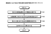
次に、実施例2におけるGAP割当部132aの処理手順について説明する。図21は、実施例2におけるGAP割当部132aの処理手順を示すフローチャートである。図21に示す処理手順は、図14に示したステップS12に相当する。
Next, a processing procedure of the
図21に示すように、まず、GAP割当部132aは、受信品質取得部131により取得された各CCの受信品質の大小関係を比較する(ステップS31)。そして、GAP割当部132aは、対応テーブルを参照して、各CCの受信品質の大小関係の比較結果に対応するGAPの占有率を読み出す(ステップS32)。そして、GAP割当部132aは、対応テーブルから読み出したGAPの占有率を用いて、所定時間において各CCに割り当てるGAPの周期を決定する(ステップS33)。そして、GAP割当部132aは、決定した周期を有するGAPをCCごとに割り当てる(ステップS34)。
As shown in FIG. 21, first, the
また、上記の図21の説明では、GAP割当部132aが対応テーブルを用いてGAPをCCごとに割り当てる場合を説明したが、図22に示すように、GAP割当部132aは、対応テーブルを参照することなく、GAPをCCごとに割り当ててもよい。この場合、GAP割当部132aは、対応テーブルを参照することなく、受信品質取得部131により取得された各CCの受信品質の大小関係に基づいて、所定時間において各CCに割り当てるGAPの周期を決定する。図22は、実施例2の変形例におけるGAP割当部132aの処理手順を示すフローチャートである。図22に示した処理手順は、図14に示したステップS12に相当する。
In the description of FIG. 21 above, the case where the
図22に示すように、まず、GAP割当部132aは、受信品質取得部131により取得された各CCの受信品質の大小関係を比較する(ステップS41)。そして、GAP割当部132aは、各CCの受信品質の順番を示すパラメータlに「1」を設定する(ステップS42)。すなわち、GAP割当部132aは、各CCの受信品質の大小関係の比較結果に基づいて、最も受信品質が悪いCCを選択する。
As shown in FIG. 22, first, the
続いて、GAP割当部132aは、各CCの受信品質の大小関係に基づいて、所定時間において選択したCCに割り当てるGAPの周期を決定する(ステップS43)。すなわち、CC#1の受信品質γ1がCC#2の受信品質γ2よりも小さい場合には、GAP割当部132aは、所定時間TにおいてCC#1に割り当てるGAPの周期を(γ1+γ2)/(2γ2)×T、CC#2に割り当てるGAPの周期を(γ1+γ2)/(2γ1)×Tに決定する。また、CC#1の受信品質γ1とCC#2の受信品質γ2とが等しい場合には、GAP割当部132aは、所定時間TにおいてCC#1に割り当てるGAPの周期およびCC#2に割り当てるGAPの周期をTに決定する。また、CC#1の受信品質γ1がCC#2の受信品質γ2よりも大きい場合には、GAP割当部132aは、所定時間TにおいてCC#1に割り当てるGAPの周期を(γ1+γ2)/(2γ1)×T、CC#2に割り当てるGAPの周期を(γ1+γ2)/(2γ2)×Tに決定する。
Subsequently, the
そして、GAP割当部132aは、決定した周期を有するGAPをCCごとに割り当てる(ステップS44)。そして、GAP割当部132aは、lを1だけインクリメントする(ステップS45)。すなわち、GAP割当部132aは、各CCの受信品質の大小関係の比較結果に基づいて、次に受信品質の悪いCCを選択する。そして、GAP割当部132aは、lがCCの総数Nccよりも大きい場合には(ステップS46肯定)、処理を終了し、lがCCの総数Nccよりも小さい場合には(ステップS46否定)、処理をステップS43に戻す。
Then, the
このように、GAP割当部132aは、受信品質取得部131により取得された各CCの受信品質に基づいて、所定時間において各CCに割り当てるGAPの周期を決定する。これにより、受信品質が相対的に悪いCCに優先的にGAPが割り当てられ、受信品質が相対的に良いCCにおけるGAPの所定時間当たりの占有率が抑えられる。
As described above, the
なお、GAP割当部132aは、受信品質取得部131により取得された各CCの受信品質に基づいて、所定時間において各CCに割り当てるGAPの時間幅を決定するようにしてもよい。
Note that the
上述してきたように、実施例2に係る基地局10aでは、GAP割当部132aが、受信品質取得部131により取得された各CCの受信品質に基づいて、所定時間において各CCに割り当てるGAPの周期または時間幅を決定する。このため、基地局10aは、周期や時間幅が異なる複数のGAPのパターンを予め記憶部に保持することを不要化することができ、記憶容量の増大を抑えつつ受信品質の悪いCCに対してGAPを高速に割り当てることができる。その結果、受信品質の良いCCを用いてデータを効率的に伝送することができるので、無線通信ネットワークシステム全体としてのデータの伝送率をより向上することができる。
As described above, in the
上記実施例1では、基地局が、各CCの受信品質が悪いほど周期の短いGAPのパターンを予め記憶された複数のGAPのパターンから選択することで、GAPをCCごとに割り当てていた。実施例3では、基地局が、各CCの受信品質に応じて1つのGAPにて受信局に測定させる周波数の数をCCごとに設定し、設定した周波数の数を用いて、所定時間において各CCに割り当てるGAPの周期または時間幅を決定する例について説明する。 In the first embodiment, the base station assigns a GAP to each CC by selecting a GAP pattern with a shorter cycle as the reception quality of each CC is worse from a plurality of GAP patterns stored in advance. In the third embodiment, the base station sets, for each CC, the number of frequencies to be measured by the receiving station using one GAP according to the reception quality of each CC, and uses the set number of frequencies to set each frequency for a predetermined time. An example of determining the period or time width of the GAP assigned to the CC will be described.
図23は、通信システムにおける基地局10bの構成例を示す図である。なお、通信システムにおける移動機の構成例は、前述した実施例1と同様の構成であるのでここではその説明を省略する。また、図23において前述した実施例1と同様の構成については同一の符号を付してその説明を省略する。
FIG. 23 is a diagram illustrating a configuration example of the
図23に示すように、基地局10bは、データ送信部11−1、11−2、データ受信部12およびGAP割当制御部13bを有する。
As illustrated in FIG. 23, the
GAP割当制御部13bは、移動機50からフィードバックされる情報に基づいて各CCに対するGAPの割り当てを制御する。図24は、GAP割当制御部13bの構成例を示す図である。GAP割当制御部13bは、受信品質取得部131およびGAP割当部132bを有する。
The GAP
GAP割当部132bは、受信品質取得部131により取得された各CCの受信品質に応じて1つのGAPにおいて移動機50に測定させる周波数の数である周波数測定数をCCごとに設定する。また、GAP割当部132bは、設定したCCごとの周波数測定数を用いて、所定時間において各CCに割り当てるGAPの周期を決定する。
The GAP allocating unit 132b sets, for each CC, a frequency measurement number that is the number of frequencies to be measured by the
ここで、GAP割当部132bによる処理の一例を説明する。なお、以下では、基地局10bと移動機50とは、Ncc(>1)個のCCを用いてデータの送受信を行うものとする。また、移動機50は、CCごとに割り当てられたGAPのうち一つのGAPにおいて最大Nfreq(>1)個の周波数を測定することが可能であり、合計Ncc×Nfreq個の周波数を測定することが可能であるものとする。また、基地局10bは、合計Ncc×Nfreq個の周波数のうちMfreq個の周波数を移動機50に測定させるものとする。
Here, an example of processing by the GAP allocation unit 132b will be described. In the following, it is assumed that the
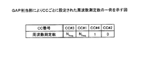
まず、GAP割当部132bは、受信品質取得部131により取得された各CCの受信品質に応じて1つのGAPにおいて移動機50に測定させる周波数の数である周波数測定数をCCごとに設定する。具体的には、GAP割当部132bは、まず、受信品質取得部131により取得された受信品質が悪い順番にNcc個のCCをソートする。そして、GAP割当部132bは、受信品質が悪い順番にソートしたNcc個のCCのうち受信品質の最も悪いものからA番目までのCCに対して、一つのGAPにおいて移動機50が測定可能な最大の周波数の数Nfreqを周波数測定数として設定する。また、GAP割当部132bは、受信品質が悪い順番にソートしたNcc個のCCのうち(A+1)番目に受信品質の悪いCCに対してB個を周波数測定数として設定する。また、GAP割当部132bは、受信品質が悪い順番にソートしたNcc個のCCのうち(A+2)番目〜Ncc番目に受信品質の悪いCCに対する周波数測定数を0とする。なお、AおよびBは、下記の式(5)および式(6)によりそれぞれ算出される。
First, the GAP allocation unit 132b sets a frequency measurement number that is the number of frequencies to be measured by the
![]()
![]()
GAP割当部132bによりCCごとに設定された周波数測定数の一例を図25に示す。図25に示す例では、Mfreq=2×Nfreq+1、Ncc=4であるものとする。また、4個のCC#1〜CC#4は、CC#3、CC#1、CC#4、CC#2の順番で受信品質が悪いものとする。図25に示すように、GAP割当部132bは、4個のCC#1〜CC#4のうち受信品質の最も悪いものからA=2番目までのCC#3およびCC#1に対して、一つのGAPにおいて移動機50が測定可能な最大の周波数の数Nfreqを周波数測定数として設定する。また、GAP割当部132bは、4個のCCのうち(A+1)=3番目に受信品質の悪いCC#4に対してB=1個を周波数測定数として設定する。また、GAP割当部132bは、4番目に受信品質の悪いCC#2に対する周波数測定数を0とする。
An example of the number of frequency measurements set for each CC by the GAP allocation unit 132b is shown in FIG. In the example shown in FIG. 25, it is assumed that M freq = 2 × N freq +1 and N cc = 4. Also, the four
続いて、GAP割当部132bは、設定したCCごとの周波数測定数を用いて、所定時間において各CCに割り当てるGAPの周期を決定する。具体的には、GAP割当部132bは、CCごとの周波数測定数が多いほど所定時間において各CCに割り当てるGAPの周期が短くなるように該GAPの周期を決定する。図25に示す例では、GAP割当部132bは、所定時間TにおいてCC#3に割り当てるGAPの周期を(Nfreq+Nfreq+1)/(3Nfreq)×Tに決定する。また、GAP割当部132bは、所定時間TにおいてCC#1に割り当てるGAPの周期を(Nfreq+Nfreq+1)/(3Nfreq)×Tに決定する。また、GAP割当部132bは、所定時間TにおいてCC#4に割り当てるGAPの周期を(Nfreq+Nfreq+1)/(3×1)×Tに決定する。
Subsequently, the GAP allocating unit 132b determines the GAP period to be allocated to each CC in a predetermined time using the set frequency measurement count for each CC. Specifically, the GAP allocation unit 132b determines the GAP cycle so that the greater the number of frequency measurements per CC, the shorter the GAP cycle allocated to each CC in a predetermined time. In the example illustrated in FIG. 25, the GAP allocation unit 132b determines the GAP cycle to be allocated to
次に、実施例3におけるGAP割当部132bの処理手順について説明する。図26は、実施例3におけるGAP割当部132bの処理手順を示すフローチャートである。図26に示す処理手順は、図14に示したステップS12に相当する。 Next, a processing procedure of the GAP allocation unit 132b in the third embodiment will be described. FIG. 26 is a flowchart illustrating the processing procedure of the GAP allocation unit 132b according to the third embodiment. The processing procedure shown in FIG. 26 corresponds to step S12 shown in FIG.
図26に示すように、GAP割当部132bは、AおよびBを算出し(ステップS51)、受信品質取得部131により取得された受信品質が悪い順番にCCをソートする(ステップS52)。そして、GAP割当部132bは、各CCの受信品質の順番を示すパラメータlに「1」を設定する(ステップS53)。すなわち、GAP割当部132bは、受信品質が悪い順番にソートしたCCのうち最も受信品質が悪いCCを選択する。
As shown in FIG. 26, the GAP allocation unit 132b calculates A and B (step S51), and sorts the CCs in the order of poor reception quality acquired by the reception quality acquisition unit 131 (step S52). Then, the GAP allocation unit 132b sets “1” to the
続いて、GAP割当部132bは、lがA以下である場合には(ステップS54肯定)、l番目に受信品質の悪いCCに対して、Nfreqを周波数測定数として設定する(ステップS55)。そして、GAP割当部132bは、lを1だけインクリメントし(ステップS56)、処理をステップS54に戻す。すなわち、GAP割当部132bは、受信品質が悪い順番にソートしたCCのうち次に受信品質が悪いCCを選択する。 Subsequently, when l is equal to or less than A (Yes at Step S54), the GAP allocation unit 132b sets N freq as the frequency measurement number for the CC having the first poorest reception quality (Step S55). Then, the GAP allocation unit 132b increments l by 1 (step S56), and returns the process to step S54. That is, the GAP allocation unit 132b selects the CC having the next poor reception quality among the CCs sorted in the order of the poor reception quality.
一方、GAP割当部132bは、lがAを超えた場合には(ステップS54否定)、(A+1)番目に受信品質の悪いCCに対してBを周波数測定数として設定する(ステップS57)。そして、GAP割当部132bは、lに「1」を再設定する(ステップS58)。すなわち、GAP割当部132bは、受信品質が悪い順番にソートしたCCのうち最も受信品質が悪いCCを再選択する。 On the other hand, if l exceeds A (No at Step S54), the GAP allocating unit 132b sets B as the frequency measurement number for the CC having the (A + 1) th lowest reception quality (Step S57). Then, the GAP allocation unit 132b resets “1” to l (step S58). That is, the GAP allocating unit 132b reselects the CC having the worst reception quality among the CCs sorted in the order of the poor reception quality.
続いて、GAP割当部132bは、lが(A+1)以下である場合には(ステップS59肯定)、設定したCCごとの周波数測定数を用いてl番目に受信品質の悪いCCに割り当てるGAPの周期を決定する(ステップS60)。 Subsequently, when l is equal to or less than (A + 1) (Yes in step S59), the GAP allocating unit 132b uses the set frequency measurement number for each CC to allocate the GAP cycle to the CC having the lowest reception quality. Is determined (step S60).
そして、GAP割当部132bは、決定した周期を有するGAPをCCごとに割り当てる(ステップS61)。そして、GAP割当部132bは、lを1だけインクリメントし(ステップS62)、処理をステップS59に戻す。すなわち、GAP割当部132bは、次に受信品質の悪いCCを再選択する。 Then, the GAP allocation unit 132b allocates a GAP having the determined period for each CC (step S61). Then, the GAP allocation unit 132b increments l by 1 (step S62), and returns the process to step S59. That is, the GAP allocating unit 132b next reselects a CC with poor reception quality.
一方、GAP割当部132bは、lが(A+1)を越えた場合には(ステップS59否定)、処理を終了する。 On the other hand, when 1 exceeds (A + 1) (No at Step S59), the GAP allocation unit 132b ends the process.
このように、GAP割当部132bは、受信品質取得部131により取得された各CCの受信品質に応じて周波数測定数をCCごとに設定する。また、GAP割当部132bは、設定したCCごとの周波数測定数を用いて、所定時間において各CCに割り当てるGAPの周期を決定する。これにより、周波数測定数が相対的に多いCCに優先的にGAPが割り当てられ、周波数測定数が相対的に少ないCCにおけるGAPの所定時間当たりの占有率が抑えられる。
Thus, the GAP allocation unit 132b sets the number of frequency measurements for each CC according to the reception quality of each CC acquired by the reception
なお、GAP割当部132bは、設定したCCごとの周波数測定数を用いて、所定時間において各CCに割り当てるGAPの時間幅を決定するようにしてもよい。 Note that the GAP allocation unit 132b may determine the time width of the GAP allocated to each CC in a predetermined time using the set frequency measurement count for each CC.
上述してきたように、実施例3に係る基地局10bでは、GAP割当部132bが、受信品質取得部131により取得された各CCの受信品質に応じて周波数測定数をCCごとに設定する。また、GAP割当部132bは、設定したCCごとの周波数測定数を用いて、所定時間において各CCに割り当てるGAPの周期を決定する。このため、基地局10bは、周波数測定数の多いCCに対してGAPを優先的に割り当てることができる。その結果、周波数測定数の少ないCCを用いてデータを効率的に伝送することができるので、無線通信ネットワークシステム全体としてのデータの伝送率をより向上することができる。
As described above, in the
10、10a、10b 基地局
11 データ送信部
12 データ受信部
13、13a、13b GAP割当制御部
50 移動機
51 データ受信部
52 データ送信部
53 受信品質測定部
131 受信品質取得部
132、132a、132b GAP割当部
133 GAP記憶部
10, 10a, 10b Base station 11
Claims (5)
前記データの送信の停止期間であるギャップを各前記無線キャリアに割り当てる場合に、取得した各前記無線キャリアの受信品質が悪いほど、より多くの前記ギャップを当該無線キャリアに割り当てるプロセッサ
を備え、
前記プロセッサは、前記取得した各前記無線キャリアの受信品質に応じて1つの前記ギャップにおいて前記受信局に測定させる周波数の数を前記無線キャリアごとに設定し、設定した前記無線キャリアごとの周波数の数を用いて、所定時間において各前記無線キャリアに割り当てる前記ギャップの周期または時間幅を決定することを特徴とする送信局。 Obtaining the reception quality of each wireless carrier reported from a receiving station that transmits and receives data to and from the device using a plurality of wireless carriers having different frequency bands,
A processor for allocating more gaps to the radio carrier as the reception quality of each acquired radio carrier is worse when allocating a gap, which is a transmission stop period of the data, to each radio carrier ;
The processor sets, for each radio carrier, the number of frequencies to be measured by the receiving station in one gap according to the acquired reception quality of each radio carrier, and sets the number of frequencies for each radio carrier thus set. And determining a period or a time width of the gap to be assigned to each of the radio carriers in a predetermined time .
前記送信局が、周波数帯が異なる複数の無線キャリアを用いて自装置とデータの送受信を行う受信局から報告される各前記無線キャリアの受信品質を取得し、前記データの送信の停止期間であるギャップを各前記無線キャリアに割り当てる場合に、各前記無線キャリアの受信品質が悪いほど、より多くの前記ギャップを当該無線キャリアに割り当て、かつ、前記取得した各前記無線キャリアの受信品質に応じて1つの前記ギャップにおいて受信局に測定させる周波数の数を前記無線キャリアごとに設定し、設定した前記無線キャリアごとの周波数の数を用いて、所定時間において各前記無線キャリアに割り当てる前記ギャップの周期または時間幅を決定する状況において、前記送信局により各前記無線キャリアに割り当てられた前記ギャップを各前記無線キャリアに設定するプロセッサと
を備えたことを特徴とする受信局。 An RF unit that transmits reception quality for each of a plurality of radio carriers having different frequency bands to a transmitting station that transmits and receives data to and from the own apparatus using the plurality of radio carriers;
The transmission station acquires the reception quality of each of the radio carriers reported from the reception station that transmits and receives data to and from its own device using a plurality of radio carriers having different frequency bands , and is a period for stopping transmission of the data When assigning a gap to each radio carrier, the worse the reception quality of each radio carrier, the more the gap is assigned to the radio carrier , and 1 depending on the acquired reception quality of each radio carrier. The number of frequencies to be measured by the receiving station in each of the two gaps is set for each radio carrier, and the period or time of the gap to be assigned to each radio carrier in a predetermined time using the set number of frequencies for each radio carrier in the context of determining the width, the gap assigned to each of said radio carrier by the transmitting station Receiving station, characterized in that a processor set to each said wireless carrier.
前記送信局は、
前記受信局から報告される各前記無線キャリアの受信品質を取得し、
前記データの送信の停止期間であるギャップを各前記無線キャリアに割り当てる場合に、取得した各前記無線キャリアの受信品質が悪いほど、より多くの前記ギャップを当該無線キャリアに割り当てる第1のプロセッサと
を備え、
前記受信局は、
複数の前記無線キャリア各々についての受信品質を、複数の前記無線キャリアを用いて前記送信局に送信するRF部と、
前記送信局により各前記無線キャリアに割り当てられた前記ギャップを各前記無線キャリアに設定する第2のプロセッサと
を備え、
前記第1のプロセッサは、前記取得した各前記無線キャリアの受信品質に応じて1つの前記ギャップにおいて前記受信局に測定させる周波数の数を前記無線キャリアごとに設定し、設定した前記無線キャリアごとの周波数の数を用いて、所定時間において各前記無線キャリアに割り当てる前記ギャップの周期または時間幅を決定することを特徴とする通信システム。 A communication system in which a transmitting station and a receiving station transmit and receive data using a plurality of radio carriers having different frequency bands,
The transmitting station is
Obtaining the reception quality of each of the radio carriers reported from the receiving station;
A first processor that allocates more gaps to the radio carrier as the received quality of each radio carrier is worse when assigning a gap, which is a data transmission stop period, to each radio carrier; Prepared,
The receiving station is
An RF unit that transmits reception quality for each of the plurality of radio carriers to the transmitting station using the plurality of radio carriers;
A second processor that sets the gap assigned to each radio carrier by the transmitting station for each radio carrier ;
The first processor sets, for each radio carrier, the number of frequencies to be measured by the receiving station in one gap according to the acquired reception quality of each radio carrier, and sets the frequency for each set radio carrier. A communication system , wherein a number of frequencies is used to determine a period or a time width of the gap to be assigned to each radio carrier in a predetermined time .
前記受信局から報告される各前記無線キャリアの受信品質を取得し、
前記データの送信の停止期間であるギャップを各前記無線キャリアに割り当てる場合に、取得された各前記無線キャリアの受信品質が悪いほど、より多くの前記ギャップを当該無線キャリアに割り当てる
ことを含み、
前記ギャップを当該無線キャリアに割り当てる処理は、
前記取得された各前記無線キャリアの受信品質に応じて1つの前記ギャップにおいて前記受信局に測定させる周波数の数を前記無線キャリアごとに設定し、設定した前記無線キャリアごとの周波数の数を用いて、所定時間において各前記無線キャリアに割り当てる前記ギャップの周期または時間幅を決定することを特徴とするギャップ割当方法。 A gap allocation method by a transmitting station that transmits and receives data to and from a receiving station using a plurality of radio carriers having different frequency bands,
Obtaining the reception quality of each of the radio carriers reported from the receiving station;
When assigning gap is the stop period of transmission of the data to each of said radio carrier, the more the reception quality of each of said radio carrier obtained is poor, see contains allocating more the gap to the wireless carrier,
The process of assigning the gap to the radio carrier
According to the received reception quality of each radio carrier, the number of frequencies to be measured by the receiving station in one gap is set for each radio carrier, and the set number of frequencies for each radio carrier is used. And determining a gap period or a time width of the gap to be allocated to each radio carrier in a predetermined time .
Priority Applications (2)
| Application Number | Priority Date | Filing Date | Title |
|---|---|---|---|
| JP2011057287A JP5732936B2 (en) | 2011-03-15 | 2011-03-15 | Transmitting station, receiving station, communication system, and gap allocation method |
| US13/413,885 US9072111B2 (en) | 2011-03-15 | 2012-03-07 | Transmission station, receiving station, wireless communication system, and wireless communication method |
Applications Claiming Priority (1)
| Application Number | Priority Date | Filing Date | Title |
|---|---|---|---|
| JP2011057287A JP5732936B2 (en) | 2011-03-15 | 2011-03-15 | Transmitting station, receiving station, communication system, and gap allocation method |
Publications (2)
| Publication Number | Publication Date |
|---|---|
| JP2012195708A JP2012195708A (en) | 2012-10-11 |
| JP5732936B2 true JP5732936B2 (en) | 2015-06-10 |
Family
ID=46828403
Family Applications (1)
| Application Number | Title | Priority Date | Filing Date |
|---|---|---|---|
| JP2011057287A Expired - Fee Related JP5732936B2 (en) | 2011-03-15 | 2011-03-15 | Transmitting station, receiving station, communication system, and gap allocation method |
Country Status (2)
| Country | Link |
|---|---|
| US (1) | US9072111B2 (en) |
| JP (1) | JP5732936B2 (en) |
Families Citing this family (7)
| Publication number | Priority date | Publication date | Assignee | Title |
|---|---|---|---|---|
| JP5205093B2 (en) * | 2008-03-21 | 2013-06-05 | 株式会社エヌ・ティ・ティ・ドコモ | User apparatus and base station apparatus |
| US20150215802A1 (en) * | 2014-01-24 | 2015-07-30 | Qualcomm Incorporated | Controlling a rate of forced measurement gap usage |
| US9112471B1 (en) | 2014-03-19 | 2015-08-18 | Freescale Semiconductor, Inc. | Gain control system for wireless communication system |
| KR102529822B1 (en) * | 2015-04-09 | 2023-05-08 | 애플 인크. | Signaling for enhanced measurement gap configuration per component carrier |
| CN107431957B (en) * | 2015-04-09 | 2021-08-06 | 苹果公司 | Cell-specific group measurement gap device, readable medium and system for carrier aggregation |
| US10021705B2 (en) * | 2015-07-08 | 2018-07-10 | Intel IP Corporation | Carrier measurements for multi-carrier devices |
| US11889438B2 (en) * | 2015-10-15 | 2024-01-30 | Telefonaktiebolaget Lm Ericsson (Publ) | Prose operation on non-serving carrier frequency |
Family Cites Families (36)
| Publication number | Priority date | Publication date | Assignee | Title |
|---|---|---|---|---|
| US7630403B2 (en) * | 2002-03-08 | 2009-12-08 | Texas Instruments Incorporated | MAC aggregation frame with MSDU and fragment of MSDU |
| JP3891145B2 (en) * | 2003-05-16 | 2007-03-14 | ソニー株式会社 | Wireless communication apparatus, wireless communication method and program |
| WO2006117838A1 (en) * | 2005-04-26 | 2006-11-09 | Mitsubishi Denki Kabushiki Kaisha | Wireless base station and base station control unit |
| JP4869256B2 (en) * | 2006-01-13 | 2012-02-08 | パナソニック株式会社 | Radio communication base station apparatus and synchronization channel signal transmission method |
| US8374108B2 (en) * | 2006-05-16 | 2013-02-12 | Sharp Kabushiki Kaisha | Mobile communication system, and mobile unit, base station unit and method therefore |
| GB2440577B (en) * | 2006-07-28 | 2011-06-29 | Nec Technologies | Trigger of inter-frequency measurements within mobile radio communications device |
| US20080085710A1 (en) * | 2006-10-05 | 2008-04-10 | Samsung Electronics Co., Ltd. | Gap scheduling method based on minimum gap patterns in long term evolution system |
| US20090325580A1 (en) * | 2006-10-12 | 2009-12-31 | Muhammad Ali Kazmi | Method and Arrangement in a Telecommunication System |
| GB2445779B (en) * | 2007-01-11 | 2009-07-08 | Samsung Electronics Co Ltd | Wireless communication system |
| JP5069546B2 (en) * | 2007-03-20 | 2012-11-07 | 株式会社エヌ・ティ・ティ・ドコモ | COMMUNICATION CONTROL METHOD, BASE STATION, AND USER DEVICE |
| US20080274742A1 (en) * | 2007-05-02 | 2008-11-06 | Motorola, Inc. | Method for performing mobility measurements among different networks |
| US20090046641A1 (en) * | 2007-08-13 | 2009-02-19 | Interdigital Patent Holdings, Inc. | Long term evolution medium access control procedures |
| KR101349824B1 (en) * | 2007-09-21 | 2014-01-15 | 엘지전자 주식회사 | Method for receiving preamble from other communication system and method for changing adaptively the measurement gap to discover the other communication system |
| TW200931869A (en) * | 2007-12-31 | 2009-07-16 | Interdigital Patent Holdings | Method and apparatus for handling interactions between measurement gap, automated repeat request, discontinuous reception and discontinuous transmission in wireless communications |
| JP5205093B2 (en) * | 2008-03-21 | 2013-06-05 | 株式会社エヌ・ティ・ティ・ドコモ | User apparatus and base station apparatus |
| CN101646251B (en) * | 2008-08-07 | 2012-07-18 | 中兴通讯股份有限公司 | Method for processing conflict of random access process and measurement clearance |
| JP2010109488A (en) | 2008-10-28 | 2010-05-13 | Sharp Corp | Mobile communication system, base station apparatus and mobile station apparatus |
| JP2010154399A (en) | 2008-12-26 | 2010-07-08 | Sharp Corp | Communication system and mobile station device |
| CN102439869B (en) * | 2009-01-30 | 2014-12-03 | 诺基亚公司 | Multiple user MIMO interference suppression communications system and methods |
| US20120051329A1 (en) | 2009-03-27 | 2012-03-01 | Panasonic Corporation | Base station and wireless communication system |
| KR101695811B1 (en) * | 2009-06-02 | 2017-01-23 | 엘지전자 주식회사 | Method of measurement over multiple downlink carriers and apparatus therefore |
| EP2273820A1 (en) * | 2009-06-30 | 2011-01-12 | Panasonic Corporation | Inter-VPLMN handover via a handover proxy node |
| US8848641B2 (en) * | 2009-09-25 | 2014-09-30 | Blackberry Limited | Methods for radio link failure recovery, and user equipment |
| US8300588B2 (en) * | 2009-10-05 | 2012-10-30 | Futurewei Technologies, Inc. | System and method for user equipment measurement timing in a relay cell |
| US20110317635A1 (en) * | 2009-12-18 | 2011-12-29 | Qualcomm Incorporated | Apparatus and method for receiving cell system information during autonomous gaps |
| US8548012B2 (en) * | 2010-01-15 | 2013-10-01 | Alcatel Lucent | Method and apparatus for reducing redundant traffic in communication networks |
| WO2011090328A2 (en) * | 2010-01-21 | 2011-07-28 | 엘지전자 주식회사 | Method for reporting the results of specific reference-cell-based quality measurement in a mobile communication system using carrier aggregation, and apparatus for the method |
| RU2554078C2 (en) * | 2010-02-19 | 2015-06-27 | Леново Груп Лимитед | Inter-frequency positioning measurements |
| EP2367385B1 (en) * | 2010-03-19 | 2012-05-16 | Telefonaktiebolaget L M Ericsson (publ) | Technique for automatic gain control in a multi-carrier communication system |
| US8451776B2 (en) * | 2010-03-31 | 2013-05-28 | Qualcomm Incorporated | Method and apparatus to facilitate support for multi-radio coexistence |
| EP2556698B1 (en) * | 2010-04-06 | 2015-11-11 | Telefonaktiebolaget L M Ericsson (publ) | Method and arrangement in a wireless communication system |
| US8359038B2 (en) * | 2010-06-15 | 2013-01-22 | Nokia Corporation | Channel access for local heterogeneous communication in a cellular network |
| KR101691666B1 (en) * | 2010-07-23 | 2017-01-02 | 엘지전자 주식회사 | Inter-Frequency Measurement Method |
| US8842564B2 (en) * | 2010-11-09 | 2014-09-23 | Telefonaktiebolaget L M Ericsson (Publ) | Method and devices for a communication system |
| CN106027578B (en) * | 2010-11-23 | 2019-09-17 | Lg电子株式会社 | Broadcast singal sending device and the method for sending broadcast singal |
| KR101995293B1 (en) * | 2011-02-21 | 2019-07-02 | 삼성전자 주식회사 | Method and appratus of activating or deactivating secondary carriers in time division duplex mobile communication system using carrier aggregation |
-
2011
- 2011-03-15 JP JP2011057287A patent/JP5732936B2/en not_active Expired - Fee Related
-
2012
- 2012-03-07 US US13/413,885 patent/US9072111B2/en not_active Expired - Fee Related
Also Published As
| Publication number | Publication date |
|---|---|
| US20120236832A1 (en) | 2012-09-20 |
| JP2012195708A (en) | 2012-10-11 |
| US9072111B2 (en) | 2015-06-30 |
Similar Documents
| Publication | Publication Date | Title |
|---|---|---|
| JP5732936B2 (en) | Transmitting station, receiving station, communication system, and gap allocation method | |
| US20220150875A1 (en) | Physical (phy) layer solutions to support use of mixed numerologies in the same channel | |
| KR100946923B1 (en) | Method and apparatus for transmitting/receiving channel quality information in a communication system using orthogonal frequency division multiplexing scheme, and system thereof | |
| JP5356232B2 (en) | Method and apparatus for high speed other sector interference (OSI) coordination | |
| US8417248B2 (en) | Methods and apparatus to schedule uplink transmissions in wireless communication systems | |
| US8451791B2 (en) | Allocation of uplink reference signals in a mobile communication system | |
| RU2382501C2 (en) | Method, transmission/reception device and system for configuring and controlling channels in wireless communication system using amc channels and diversity channels | |
| KR101192082B1 (en) | Wireless communication device and wireless communication method | |
| US10505665B2 (en) | Method for modulation and coding scheme selection and related network nodes and terminal devices | |
| US20150003370A1 (en) | Control station device, wireless communication system, allocation method and program | |
| JP6901088B2 (en) | Wireless communication device and wireless communication method | |
| US8923329B2 (en) | Apparatus and method for supporting various system bandwidths in a broadband wireless communication system | |
| US20110319113A1 (en) | Base station apparatus and information transmitting method | |
| US20090268686A1 (en) | Wireless transmitter and wireless transmission method | |
| JP2016052101A (en) | Wireless communication system, centralized control station, base station, terminal station, and wireless communication method | |
| WO2008035706A1 (en) | Radio communication device, radio communication system, and radio communication method | |
| KR101308681B1 (en) | Apparatus and method for allocating resource based on reliablity of feedback channel in broadband wireless communication system | |
| JP2013066018A (en) | Wireless communication device and wireless communication system | |
| JP4703253B2 (en) | Communication terminal device | |
| KR100964215B1 (en) | Method and apparatus for transmitting/receiving channel quality information in a communication system using orthogonal frequency division multiplexing scheme | |
| JP2010279052A (en) | Wireless communication system and wireless communication method | |
| WO2010095468A1 (en) | Wireless communication system, wireless communication method, wireless communication device, and program | |
| JP2010110013A (en) | Base station device |
Legal Events
| Date | Code | Title | Description |
|---|---|---|---|
| A621 | Written request for application examination |
Free format text: JAPANESE INTERMEDIATE CODE: A621 Effective date: 20131129 |
|
| A977 | Report on retrieval |
Free format text: JAPANESE INTERMEDIATE CODE: A971007 Effective date: 20140523 |
|
| A131 | Notification of reasons for refusal |
Free format text: JAPANESE INTERMEDIATE CODE: A131 Effective date: 20140603 |
|
| A521 | Request for written amendment filed |
Free format text: JAPANESE INTERMEDIATE CODE: A523 Effective date: 20140703 |
|
| A02 | Decision of refusal |
Free format text: JAPANESE INTERMEDIATE CODE: A02 Effective date: 20141224 |
|
| A521 | Request for written amendment filed |
Free format text: JAPANESE INTERMEDIATE CODE: A523 Effective date: 20150204 |
|
| A911 | Transfer to examiner for re-examination before appeal (zenchi) |
Free format text: JAPANESE INTERMEDIATE CODE: A911 Effective date: 20150225 |
|
| TRDD | Decision of grant or rejection written | ||
| A01 | Written decision to grant a patent or to grant a registration (utility model) |
Free format text: JAPANESE INTERMEDIATE CODE: A01 Effective date: 20150317 |
|
| A61 | First payment of annual fees (during grant procedure) |
Free format text: JAPANESE INTERMEDIATE CODE: A61 Effective date: 20150330 |
|
| R150 | Certificate of patent or registration of utility model |
Ref document number: 5732936 Country of ref document: JP Free format text: JAPANESE INTERMEDIATE CODE: R150 |
|
| LAPS | Cancellation because of no payment of annual fees |