JP5732888B2 - Display device and display method - Google Patents
Display device and display method Download PDFInfo
- Publication number
- JP5732888B2 JP5732888B2 JP2011029064A JP2011029064A JP5732888B2 JP 5732888 B2 JP5732888 B2 JP 5732888B2 JP 2011029064 A JP2011029064 A JP 2011029064A JP 2011029064 A JP2011029064 A JP 2011029064A JP 5732888 B2 JP5732888 B2 JP 5732888B2
- Authority
- JP
- Japan
- Prior art keywords
- display
- viewpoint
- observer
- image
- switching
- Prior art date
- Legal status (The legal status is an assumption and is not a legal conclusion. Google has not performed a legal analysis and makes no representation as to the accuracy of the status listed.)
- Expired - Fee Related
Links
Images


Classifications
-
- H—ELECTRICITY
- H04—ELECTRIC COMMUNICATION TECHNIQUE
- H04N—PICTORIAL COMMUNICATION, e.g. TELEVISION
- H04N13/00—Stereoscopic video systems; Multi-view video systems; Details thereof
- H04N13/30—Image reproducers
- H04N13/366—Image reproducers using viewer tracking
-
- H—ELECTRICITY
- H04—ELECTRIC COMMUNICATION TECHNIQUE
- H04N—PICTORIAL COMMUNICATION, e.g. TELEVISION
- H04N13/00—Stereoscopic video systems; Multi-view video systems; Details thereof
- H04N13/30—Image reproducers
- H04N13/302—Image reproducers for viewing without the aid of special glasses, i.e. using autostereoscopic displays
- H04N13/31—Image reproducers for viewing without the aid of special glasses, i.e. using autostereoscopic displays using parallax barriers
- H04N13/315—Image reproducers for viewing without the aid of special glasses, i.e. using autostereoscopic displays using parallax barriers the parallax barriers being time-variant
-
- H—ELECTRICITY
- H04—ELECTRIC COMMUNICATION TECHNIQUE
- H04N—PICTORIAL COMMUNICATION, e.g. TELEVISION
- H04N2213/00—Details of stereoscopic systems
- H04N2213/007—Aspects relating to detection of stereoscopic image format, e.g. for adaptation to the display format
Landscapes
- Engineering & Computer Science (AREA)
- Multimedia (AREA)
- Signal Processing (AREA)
- Testing, Inspecting, Measuring Of Stereoscopic Televisions And Televisions (AREA)
- Controls And Circuits For Display Device (AREA)
Description
本発明は、表示装置及び表示方法に関し、特に複数の視点画像を表示する表示装置及び表示方法に関する。 The present invention relates to a display device and a display method, and more particularly to a display device and a display method for displaying a plurality of viewpoint images.
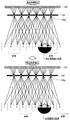
近年、左右の目に互いに異なった視点画像を導光することにより、立体映像の視聴を可能とする裸眼用の立体視表示装置(以下、表示装置と称呼する。)が普及しつつある。表示装置は、パララックスバリアやレンチキュラーレンズを用いて複数の視点画像のうち所定の視点画像を観察者の眼球に導光する。図8に示した表示装置90では、パララックスバリア905の透過部905aを通過する光線のうち、視点5,6の視点画像が観察者の左目、右目にそれぞれ導光されることにより、画像の立体視が可能になる。
In recent years, autostereoscopic display devices (hereinafter referred to as display devices) that enable viewing of stereoscopic images by guiding different viewpoint images to the left and right eyes are becoming widespread. The display device guides a predetermined viewpoint image among a plurality of viewpoint images to the eyeball of the observer using a parallax barrier or a lenticular lens. In the
表示部900の表示画面上の各画素には、各視点画像が周期的に配置されている。このため、各周期の境界部分(例えば、6視点の場合には視点6と視点1)では、右目に入るべき視点映像が左目に導光され、左目に入るべき視点映像が右目に導光される逆視現象が発生する。逆視領域では、観察者は立体画像の手前と奥とが反転した映像を知覚する、あるいは不自然に融合して見えるという違和感のある映像を見ることになる。
Each viewpoint image is periodically arranged in each pixel on the display screen of the
逆視現象は、裸眼用の表示装置において原理的に生じるものであるため根本的な解決は難しい。そこで、従来から、観察者の顔の位置を検出し、観察者の位置が逆視領域に入らないように制御する技術が提案されている。例えば、特許文献1,2には、観察者が逆視領域にいる又は逆視領域に近づいた場合、観察者の位置が逆視領域でなくなるように、多視点画像の表示位置を連続的に切り替える表示方法が提案されている。たとえば、図8では、上図で視点1〜6の視点画像を表示していたのに対して、下図で視点3〜8の視点画像を表示するように、多視点画像の表示位置を視点1〜6→視点2〜7→視点3〜8と「連続的に」切り替え、これにより、観察者の位置が正視領域になるようにしている。
Since the reverse vision phenomenon occurs in principle in a display device for the naked eye, a fundamental solution is difficult. Therefore, conventionally, a technique has been proposed in which the position of the observer's face is detected and control is performed so that the observer's position does not enter the reverse viewing region. For example, in
しかし、上記方法により正視領域を拡大するためには、かなり多くの視点画像を入力または生成しておく必要があり、画像処理の負担が大きかった。 However, in order to enlarge the normal viewing area by the above method, it is necessary to input or generate a large number of viewpoint images, and the burden of image processing is large.
表示画面に表示する画像の視点数を多くすることにより正視領域を拡大することも考えられる。しかし、表示画面に表示する視点数が多くなるほど画像の解像度が悪くなる。よって、正視領域を拡大するためにむやみに視点数を増やすと画質が低下してしまう。 It is also conceivable to enlarge the normal viewing area by increasing the number of viewpoints of the image displayed on the display screen. However, the greater the number of viewpoints displayed on the display screen, the worse the image resolution. Therefore, if the number of viewpoints is increased unnecessarily in order to enlarge the normal viewing area, the image quality is degraded.
上記課題に対して、本発明の目的とするところは、複数の視点画像を表示する表示装置にて観察者が視聴しやすい環境を整えることが可能な、新規かつ改良された表示装置及び表示方法を提供することにある。 In view of the above problems, an object of the present invention is to provide a new and improved display device and display method capable of preparing an environment in which an observer can easily view a display device that displays a plurality of viewpoint images. Is to provide.
上記課題を解決するために、本発明のある観点によれば、複数の視点画像を表示する表示部と、複数の透過部を有し、前記表示部からの光を分離させる光分離部と、前記視点画像のフレーム間の相関情報に基づき、前記表示部上の各視点画像の表示位置又は前記光分離部の各透過部の透過率の少なくともいずれかを切り替えるタイミングを制御する表示制御部と、を備える表示装置が提供される。 In order to solve the above problems, according to an aspect of the present invention, a display unit that displays a plurality of viewpoint images, a light separation unit that includes a plurality of transmission units and separates light from the display unit, A display control unit that controls timing for switching at least one of the display position of each viewpoint image on the display unit or the transmittance of each transmission unit of the light separation unit based on correlation information between frames of the viewpoint image; Is provided.
前記表示制御部は、前記視点画像のフレーム間の相関情報として検出された視点画像のシーンチェンジに基づき、前記切り替えタイミングを制御してもよい。 The display control unit may control the switching timing based on a scene change of the viewpoint image detected as correlation information between frames of the viewpoint image.
前記表示制御部は、前記視点画像のフレーム間の相関情報として検出された視点画像の変動度の大きさに基づき、前記切り替えタイミングを制御してもよい。 The display control unit may control the switching timing based on a magnitude of the degree of variation of the viewpoint image detected as correlation information between frames of the viewpoint image.
前記表示制御部は、観察者の位置を取得し、前記切り替えタイミングに前記複数の視点画像の中心画像が前記観察者の位置に近づくように前記各視点画像の表示位置又は前記各透過部の透過率の少なくともいずれかを切り替えてもよい。 The display control unit acquires the position of the observer, and the display position of each viewpoint image or the transmission of each transmission part so that the central image of the plurality of viewpoint images approaches the position of the observer at the switching timing. At least one of the rates may be switched.
前記表示制御部は、観察者の位置を取得し、前記切り替えタイミングに前記複数の視点画像の中心画像が前記観察者の位置に配置されるように前記各視点画像の表示位置又は前記各透過部の透過率の少なくともいずれかを切り替えてもよい。 The display control unit acquires the position of the observer, and the display position of each viewpoint image or the transmission part so that a central image of the plurality of viewpoint images is arranged at the position of the observer at the switching timing. At least one of the transmittances may be switched.
前記表示制御部は、観察者の位置を取得し、前記切り替えタイミングに前記複数の視点画像の中心画像が前記観察者の位置に配置されていない場合、該視点画像の中心画像が前記観察者の位置に近づくように前記各視点画像の表示位置又は前記各透過部の透過率の少なくともいずれかを切り替えてもよい。 The display control unit acquires the position of the observer, and when the center image of the plurality of viewpoint images is not arranged at the position of the observer at the switching timing, the center image of the viewpoint image is the position of the observer. You may switch at least any one of the display position of each said viewpoint image, or the transmittance | permeability of each said permeation | transmission part so that it may approach a position.
前記表示制御部は、観察者の位置を取得し、前記切り替えタイミングに前記観察者が逆視領域にいる場合、前記各視点画像の表示位置又は前記各透過部の透過率の少なくともいずれかを切り替えてもよい。 The display control unit acquires the position of the observer, and switches the display position of each viewpoint image or the transmittance of each transmission part when the observer is in the reverse viewing region at the switching timing. May be.
前記表示制御部は、観察者の位置を取得し、前記切り替えタイミングに前記観察者が逆視領域又は該逆視領域に隣接する準正視領域にいる場合、前記各視点画像の表示位置又は前記各透過部の透過率の少なくともいずれかを切り替えてもよい。 The display control unit acquires the position of the observer, and when the observer is in a reverse vision region or a quasi-normal vision region adjacent to the reverse vision region at the switching timing, the display position of each viewpoint image or each You may switch at least any one of the transmittance | permeability of a permeation | transmission part.
前記表示制御部は、観察者の位置を取得し、前記切り替えタイミングに前記観察者が正視領域にいる場合、前記各視点画像の表示位置又は前記各透過部の透過率の少なくともいずれかの切り替えを行わなくてもよい。 The display control unit acquires the position of the observer, and switches the display position of each viewpoint image or the transmittance of each transmission part when the observer is in the normal viewing area at the switching timing. It does not have to be done.
前記表示制御部は、前記観察者の位置の変化が所定の閾値以下の場合、前記各視点画像の表示位置又は前記各透過部の透過率の少なくともいずれかの切り替えを行わなくてもよい。 The display control unit may not switch at least one of the display position of each viewpoint image and the transmittance of each transmission unit when the change in the position of the observer is equal to or less than a predetermined threshold.
前記表示制御部は、複数の観察者の位置を取得し、前記切り替え後、前記複数の観察者のすべてが正視領域で視聴可能な場合、前記切り替えタイミングに前記各視点画像の表示位置又は前記各透過部の透過率の少なくともいずれかを切り替えてもよい。 The display control unit acquires the positions of a plurality of observers, and after the switching, when all of the plurality of observers can view in a normal viewing area, the display position of each viewpoint image or each of the viewpoint images at the switching timing. You may switch at least any one of the transmittance | permeability of a permeation | transmission part.
また、上記課題を解決するために、本発明の別の観点によれば、表示部に表示された複数の視点画像のフレーム間の相関情報を取得するステップと、前記取得された前記視点画像のフレーム間の相関情報に基づき前記表示部上の各視点画像の表示位置又は前記表示部からの光を分離させる複数の透過部を有する光分離部の各透過部の透過率の少なくともいずれかを切り替えるタイミングを制御するステップと、を含む表示方法が提供される。 In order to solve the above problem, according to another aspect of the present invention, a step of acquiring correlation information between frames of a plurality of viewpoint images displayed on a display unit; Based on the correlation information between the frames, at least one of the display position of each viewpoint image on the display unit or the transmittance of each transmission unit of the light separation unit having a plurality of transmission units that separate light from the display unit is switched. Controlling the timing, and a display method is provided.
以上説明したように、本発明によれば、複数の視点画像を表示する表示装置にて観察者が視聴しやすい環境を整えることができる。 As described above, according to the present invention, it is possible to prepare an environment in which an observer can easily view a display device that displays a plurality of viewpoint images.
以下に添付図面を参照しながら、本発明の各実施形態について詳細に説明する。なお、本明細書及び図面において、実質的に同一の機能構成を有する構成要素については、同一の符号を付することにより重複説明を省略する。 Hereinafter, embodiments of the present invention will be described in detail with reference to the accompanying drawings. In addition, in this specification and drawing, about the component which has the substantially same function structure, duplication description is abbreviate | omitted by attaching | subjecting the same code | symbol.
なお、本発明の実施形態は次の順序で説明される。
<一実施形態>
[表示装置の概略構成]
[表示装置の機能構成]
[表示装置の動作]
<変形例1>
[表示装置の動作]
<変形例2>
[表示装置の動作]
The embodiments of the present invention will be described in the following order.
<One Embodiment>
[Schematic configuration of display device]
[Functional structure of display device]
[Operation of display device]
<Modification 1>
[Operation of display device]
<
[Operation of display device]
<一実施形態>
[表示装置の概略構成]
まず、本発明の一実施形態に係る表示装置の概略構成について説明する。図1及び図2に示すように、本実施形態に係る表示装置10は、表示部100及びパララックスバリア105を有し、立体視画像を表示する。表示部100は、複数の視点画像を表示する。本実施形態では、表示部100には6視点の視点画像が周期的に配置されている。パララックスバリア105は、各視点画像から右目用の画像及び左目用の画像を分離させる。図2に示したように、パララックスバリア105は、複数の透過部105aを有し、各透過部105aの透過率を変えることにより、表示部100からの光を分離させる。
<One Embodiment>
[Schematic configuration of display device]
First, a schematic configuration of a display device according to an embodiment of the present invention will be described. As shown in FIGS. 1 and 2, the
表示部100は、例えばLCD(Liquid Crystal Display)、PDP(Plasma Display Panel)、または有機EL(Electro-Luminescence)パネルなどのディスプレイであってもよい。
The
パララックスバリア105は、表示部100からの光を分離させる光分離部の一例である。光分離部の他の例としては、レンチキュラーレンズ等のパララックス素子が挙げられる。パララックス素子としては、3Dモード固定のパッシブ素子や、2D/3D切り替えが可能なアクティブ素子が考えられるが、本実施形態においては、これらを限定しない。また、本実施形態では、パララックスバリア105は、表示部100の画素面の前方に置かれているが、これに限られず、表示部100の後方に置かれてもよい。
The
本実施形態では、図1に示したように、観察者は、パララックスバリア105を通して各視点画像を見るため、正視領域では右目には右目用の画像だけが入り、左目には左目用の画像だけが入る。このようにして右目に見える映像と左目に見える映像とが異なることにより、立体表示部100aに映し出される映像は立体的に見える。
In the present embodiment, as shown in FIG. 1, the observer views each viewpoint image through the
視点数が6の場合、6つの視点画像が、表示部100の各画素の位置に周期的に配置される。表示部100の前のパララックスバリア105は、透過部105aにより6視点の視点画像をそれぞれ空間的に分離させる。図1では、観察者は、右目で右目用の視点4の視点画像を観察し、左目で左目用の視点3の視点画像を観察している。ここでは、観察者は、6視点の視点画像のうちの中心画像である、視点3、4の視点画像を観察するため、逆視領域に最も遠い、最もよい位置にいるといえる。このように初期位置では、観察者は中心画像を見る位置にいる。
When the number of viewpoints is 6, six viewpoint images are periodically arranged at the position of each pixel of the
(逆視領域/準正視領域)
前述したように、視点画像が周期的に配置されることにより、各周期の境界部分では右目に入るべき視点映像が左目に導光され、左目に入るべき視点映像が右目に導光される逆視領域が存在する。逆視領域では、観察者に不快な映像を見せることになるため好ましくない。
(Reverse Viewing Area / Quasi-Normal Viewing Area)
As described above, when the viewpoint images are periodically arranged, the viewpoint video that should enter the right eye is guided to the left eye and the viewpoint video that should enter the left eye is guided to the right eye at the boundary portion of each cycle. There is a viewing area. In the reverse viewing region, an unpleasant image is shown to the observer, which is not preferable.
逆視領域での視聴を避けるためには、例えば、図8の上図に示したように、観察者が逆視領域にいるか、逆視領域に近づいた場合、観察者の位置が正視領域になるように、多視点画像の表示位置を「連続的に」切り替えて表示する方法が考えられる。図8では、上図で視点1〜6の視点画像を表示していたのに対して、下図で視点3〜8の視点画像を表示するように、多視点画像の表示位置を視点1〜6→視点2〜7→視点3〜8と「連続的に」切り替えている。
In order to avoid viewing in the reverse vision region, for example, as shown in the upper diagram of FIG. 8, when the observer is in the reverse vision region or approaches the reverse vision region, the position of the observer is changed to the normal vision region. Thus, a method of switching the display positions of the multi-viewpoint images “continuously” and displaying them can be considered. In FIG. 8, the viewpoint images of the viewpoints 1 to 6 are displayed in the upper diagram, but the display positions of the multi-viewpoint images are set to the viewpoints 1 to 6 so that the viewpoint images of the
このように正視領域をずらすためには、かなり多くの視点画像を入力または生成して用意しておく必要がある。しかし、多くの視点画像を用意する際、画像処理量が多く、処理の負担が大きくなってしまう。よって、以下に説明する本実施形態では、複数の視点画像を表示する表示装置にて観察者が視聴しやすい環境を整える方法を提案する。 In order to shift the normal viewing area in this way, it is necessary to prepare or input a large number of viewpoint images. However, when many viewpoint images are prepared, the amount of image processing is large, and the processing burden increases. Therefore, the present embodiment described below proposes a method for preparing an environment in which an observer can easily view a display device that displays a plurality of viewpoint images.
なお、逆視領域以外は正視領域であるが、本明細書では、逆視領域と正視領域とに跨った領域を準正視領域とも称呼する。例えば、図1では、視点6、1の視点画像を視聴する領域が逆視領域である。これに対して、逆視領域の両側の領域、つまり、視点画像が視点5、視点6となる領域、及び視点画像が視点1、視点2となる領域が準正視領域である。しかしながら、準正視領域は、これに限られず、より多くの領域を準正視領域としてもよいし、準正視領域を設けなくてもよい。
In addition, although it is a normal vision area | region except a reverse vision area | region, in this specification, the area | region straddling a reverse vision area and a normal vision area | region is also called a quasi-normal vision area. For example, in FIG. 1, the region for viewing the viewpoint images of the viewpoints 6 and 1 is the reverse viewing region. On the other hand, the regions on both sides of the reverse vision region, that is, the region where the viewpoint image is the viewpoint 5 and the viewpoint 6 and the region where the viewpoint image is the viewpoint 1 and the
[表示装置の機能構成]
本実施形態に係る表示装置10の機能構成について図3を参照しながら説明する。本実施形態に係る表示装置10は、表示部100、パララックスバリア105、視点位置検出部110、多視点画像生成部115、フレーム間相関検出部120、表示制御部125、表示駆動部130及び記憶部135を有する。表示部100及びパララックスバリア105については、上述したため、ここでは説明を省略し、他の機能部についての説明に留める。
[Functional structure of display device]
A functional configuration of the
視点位置検出部110は、図示しないカメラを用いて観察者を撮像し、得られた画像から観察者の顔を認識する。市販のデジタルスチルカメラにおいて、顔を検出してフォーカシングするといった機能を持つものがあるように、顔検出技術として存在する既存技術を用いることができる。また、テンプレートと比較することにより撮像された顔を識別する顔認識の既存技術も用いることができる。本実施形態では、このような公知のあらゆる顔認識技術を使うことができる。なお、カメラの仕様としては、Webカメラのような動画像を撮像できるものを仕様してもよい。また、一般的に距離計測を行うためには2台以上のカメラが必要であるが、1台のカメラでも物体認識技術により距離情報を取得することができる。
The viewpoint
視点位置検出部110は、このようにして撮影した画像データから顔検出機能により、観察者が存在する方向を検出する。視点位置検出部110は、認識された観察者の顔から観察者の位置と距離を算出する。観察者が複数存在する場合には、視点位置検出部110は、全観察者の位置と距離を算出する。視点位置検出部110により行われる距離の測定方法としては、大きく次の2つが考えられる。
The viewpoint
距離測定方法の1つとしては、観察者は、ある決められた位置(例えば画面中央より2mの位置)に移動し、その位置においてカメラと用いて顔を撮影する。そのときに撮像される顔画像の大きさを基準とする。基準画像の撮像は、コンテンツ視聴前に初期設定としての処理を行う。より具体的には、視点位置検出部110は、視距離に対する画像上の平均的な顔の大きさを予め調べておき、記憶部135に記録しておく。検出した観察者の顔画像の大きさと記憶部135に記憶されたデータとを比較し、対応する距離データを読み出すことにより、観察者の位置情報及び表示部100から観察者までの距離情報を取得することができる。なお、視点位置検出部110は、観察者の位置を検出するために、顔検出機能を用いたフェイストラッキングを用いてもよいが、これに限られず、例えば、ヘッドトラッキングやアイトラッキングを用いてもよい。
As one of the distance measurement methods, the observer moves to a predetermined position (for example, a position 2 m from the center of the screen), and photographs a face using the camera at that position. The size of the face image captured at that time is used as a reference. The reference image is picked up as an initial setting before viewing the content. More specifically, the viewpoint
距離測定方法の他の1つとしては、上記顔認識機能により観察者の左右の眼の検出が可能である。カメラにより撮像された左右の眼のそれぞれの重心位置の距離を算出する。一般に、裸眼用の立体ディスプレイには、設計視距離がある。また、人間の左右の瞳孔間距離(眼間距離)は平均65mmといわれている。瞳孔間距離65mmの観察者がカメラから「設計視距離」だけ離れたときを基準とし、視点位置検出部110は、上記顔認識動作の際、算出された左右の眼の重心位置の距離から観察者までの距離を算出する。
As another distance measuring method, the left and right eyes of the observer can be detected by the face recognition function. The distance between the center positions of the left and right eyes captured by the camera is calculated. In general, a stereoscopic display for the naked eye has a design viewing distance. Further, it is said that the distance between the left and right pupils of the human (interocular distance) is 65 mm on average. The viewpoint
多視点画像生成部115は、複数の視点画像を入力又は生成する。本実施形態では、6視点の視点画像が入力されるか、又は入力画像から6視点の視点画像が生成される。
The multi-viewpoint
フレーム間相関検出部120は、視点画像のフレーム間の相関情報を検出し、表示制御部125に出力する。視点画像のフレーム間の相関情報の一例としては、視点画像のシーンチェンジが挙げられる。この場合、視点画像のシーンチェンジが検出されたとき、視点画像が切り替えられることになる。
The inter-frame
シーンとは、例えば、空間的に連続するひとまとまりの画像区間(画像クリップ)を意味し、シーンチェンジとは、例えば、シーンの切り替え点、すなわち、時間的若しくは空間的に不連続な画像クリップ同士が連結された境界である画像の変化点を意味する。なお、シーンチェンジは、カットチェンジ、ショットチェンジ、画像変化点等と称されることもあるが、本明細書ではシーンチェンジと称する。 A scene means, for example, a group of spatially continuous image segments (image clips), and a scene change means, for example, a scene switching point, that is, temporally or spatially discontinuous image clips. Means the change point of the image, which is the connected boundary. A scene change is sometimes called a cut change, a shot change, an image change point, or the like, but is called a scene change in this specification.
例えば、フレーム間相関検出部120は、フレーム間の画像の輝度が大きく変わった場合をシーンチェンジとして検出してもよい。また、フレーム間相関検出部120は、フレーム間の画像のカラーバランスの変化、フレーム間の画像の色の変化、フレーム間の画像におけるテロップなどの出現等からシーンチェンジを検出してもよい。
For example, the inter-frame
フレーム間相関検出部120により実行されるシーンチェンジの検出には公知のあらゆる技術を用いることができる。シーンチェンジの検出方法の一例としては、統計量差分法、画像差分法、符号化データ法、エッジ法、ヒストグラム差分法等が挙げられる。
Any known technique can be used to detect a scene change executed by the inter-frame
例えば、MPRGのDCT(離散コサイン変換)のDC係数の所定フレーム間差分や所定ヒストグラムデータ量の相違、または画像のベースバンド帯域での輝度信号、若しくは色信号の所定ヒストグラムデータ量のフレーム間差分等により所定のシーンチェンジを検出することができる。また、画像のエッジ量が変化する特性を用いて行われる所定の信号処理によりフェードやワイプといったゆっくりとしたシーンチェンジを検出することができる。このように、シーンチェンジの検出には、上記技術を用いて、画像上の場面の切り替えによるカットチェンジ、画像上のディゾルブやフェードやワイプによるシーンチェンジ等を検出することが含まれる。また、取得される画像内に予め埋め込まれたチャプタ点の情報を検出することにより、シーンチェンジを検出してもよい。 For example, the difference between predetermined frames of the DC coefficient of DCRG (discrete cosine transform) of MPRG and the difference of predetermined histogram data amount, or the difference between frames of the predetermined histogram data amount of luminance signal or color signal in the baseband band of the image, etc. Thus, a predetermined scene change can be detected. Further, a slow scene change such as fading or wiping can be detected by predetermined signal processing performed using a characteristic that changes the edge amount of an image. As described above, detection of a scene change includes detection of a cut change caused by scene switching on an image, a scene change caused by a dissolve, fade, or wipe on the image using the above-described technique. Further, a scene change may be detected by detecting chapter point information embedded in advance in the acquired image.
視点画像のフレーム間の相関情報の他の例としては、視点画像の変動度の大きさが挙げられる。この場合、視点画像の変動度が予め定められた所定の閾値以上の大きさとなったとき、視点画像が切り替えられることになる。例えば、カメラワークのように、シーンが切り替わるのではなく、カメラがある方向に動いているような場合や、ズームインやズームアウト等カメラのカットは変わらないが視点画像全体が変動している場合が検出対象となる。 Another example of the correlation information between the frames of the viewpoint image is the magnitude of the degree of variation of the viewpoint image. In this case, the viewpoint image is switched when the degree of variation of the viewpoint image is greater than or equal to a predetermined threshold value. For example, when the scene is not switched, as in camera work, the camera moves in a certain direction, or the camera cuts such as zoom in and zoom out do not change, but the entire viewpoint image changes. It becomes a detection target.
変動度の大きさの検出方法としては、例えば、動きベクトルを用いて視点画像の変動度の大きさを推測することができる。また、画像中の撮影対象の移動や変形、高速に移動する物体の出現や消滅の変化などから視点画像の変動度の大きさを検出してもよい。また、カメラの絞りなどの情報をカメラ側から取得することにより、視点画像の変動度の大きさを検出してもよい。なお、以上に示した視点画像のフレーム間の相関とは、動画像だけが対象ではなく、静止画の画像間の相関も含む。 As a method of detecting the degree of variation, for example, the degree of variation of the viewpoint image can be estimated using a motion vector. Further, the magnitude of the degree of variation of the viewpoint image may be detected from the movement or deformation of the shooting target in the image, the change in the appearance or disappearance of an object that moves at high speed, and the like. Further, the degree of variation of the viewpoint image may be detected by acquiring information such as the aperture of the camera from the camera side. The above-described correlation between frames of viewpoint images includes not only a moving image but also a correlation between still image images.
表示制御部125は、多視点画像生成部115により生成された視点画像を図1の初期位置に表示するように制御する。例えば、表示装置10がテレビの場合には、テレビの3Dモードをオンした時、又は、3Dのテレビの電源をオンした時に、視点位置を検出して観察者に多視点画像の中心画像を提示する。
The
表示制御部125は、視点画像のフレーム間の相関情報に基づき、表示部100上の各視点画像の表示位置又はパララックスバリア105の各透過部の透過率のいずれかを切り替えるタイミングを制御する。表示制御部125は、切り替えのタイミングになったら、観察者の目の位置に中心画像が表示されるように、表示部100の表示位置又はパララックスバリア105の複数の透過部105aの透過率のいずれかを切り替える。例えば、表示制御部125は、視点画像のフレーム間の相関情報が低い場面で上記切り替えを行うように制御する。視点画像のフレーム間の相関情報が低い場面とは、視点画像のシーンチェンジを検出した場合や、視点画像の変動度が所定以上の大きさになったことを検出した場合である。
The
表示制御部125は、観察者の位置を取得し、前記切り替えタイミングに、生成された視点画像の中心画像が前記観察者の位置に近づくように各視点画像の表示位置又は各透過部の透過率の少なくともいずれかを切り替えてもよい。
The
また、表示制御部125は、観察者の位置を取得し、前記切り替えタイミングに、生成された視点画像の中心画像が前記観察者の位置に配置されるように前記各視点画像の表示位置又は前記各透過部の透過率の少なくともいずれかを切り替えてもよい。
In addition, the
また、表示制御部125は、観察者の位置を取得し、前記切り替えタイミングに、生成された視点画像の中心画像が前記観察者の位置に配置されていない場合、該視点画像の中心画像が前記観察者の位置に近づくように各視点画像の表示位置又は各透過部の透過率の少なくともいずれかを切り替えてもよい。
Further, the
また、表示制御部125は、観察者の位置を取得し、前記切り替えタイミングに前記観察者が逆視領域にいる場合、前記各視点画像の表示位置又は前記各透過部の透過率の少なくともいずれかを切り替えてもよい。
Further, the
また、表示制御部125は、観察者の位置を取得し、前記切り替えタイミングに前記観察者が逆視領域又は該逆視領域に隣接する準正視領域にいる場合、前記各視点画像の表示位置又は前記各透過部の透過率の少なくともいずれかを切り替えてもよい。
In addition, the
また、表示制御部125は、観察者の位置を取得し、前記切り替えタイミングに前記観察者が正視領域にいる場合、前記各視点画像の表示位置又は前記各透過部の透過率の少なくともいずれかの切り替えを行わないようにしてもよい。
In addition, the
また、表示制御部125は、観察者の位置の変化が所定の閾値以下の場合、前記各視点画像の表示位置又は前記各透過部の透過率の少なくともいずれかの切り替えを行わないようにしてもよい。
Further, the
また、表示制御部125は、複数の観察者の位置を取得し、前記切り替え後、前記複数の観察者のすべてが正視領域で視聴可能な場合、前記切り替えタイミングに前記中心画像が各観察者の位置に近づくように前記各視点画像の表示位置又は前記各透過部の透過率の少なくともいずれかを切り替えてもよい。
Further, the
なお、前記各視点画像の表示位置を切り替えるとは、各視点画像を表示する担当画素を切り替えることをいう。また、可変のパララックスバリアの各透過部の透過率を切り替えるとは、バリアに配置された電極にどのような大きさの電圧を印加するかによって各透過部105aの透過率の高低を制御することをいうが、パララックスバリアの物理的な位置を変えてもよい。
Note that switching the display position of each viewpoint image means switching the assigned pixel for displaying each viewpoint image. In addition, switching the transmittance of each transmissive part of the variable parallax barrier is to control the level of the transmittance of each
表示駆動部130は、表示部100とパララックスバリア105のそれぞれを上記の方法で電気的又は物理的に駆動する。
The
記憶部135は、表示制御部125等の各部の機能を実現するためのプログラムや各種データが記憶されている。
The
なお、表示装置10は、例えばテレビやPC、モバイル機器などであり得るが、必ずしも同じ筐体に表示部100を含む必要はない。例えば、表示部100は、表示装置10と一体であってその表面に設けられてもよいし、表示装置10には含まれずに独立して設けられていてもよい。また、表示装置10は、必ずしも同じ筐体に上記各構成要素のすべてを含む必要はない。例えば、記憶部135は表示装置10には含まれずに、例えばネットワーク上のストレージによってその機能が提供されてもよい。
Note that the
表示装置10は、画像を適切な位置に表示するための各種演算を行う演算処理部を有しており、例えばGPU(Graphics Processing Unit)、CPU(Central Processing Unit)、またはDSP(Digital Signal Processor)などによって実現されうる。表示装置10の各部は、記憶部135に格納されたプログラムに従って動作してもよい。
The
[表示装置の動作]
次に、図4のフローチャートを参照しながら、本実施形態に係る表示装置10の動作について説明する。図4で処理が開始されると、ステップS400にて、視点位置検出部110は、カメラに視聴環境を撮像させ、撮像空間内の顔を検出し、観察者空間内の観察者の位置を検出する。次に、ステップS405にて、表示制御部125は、シーンチェンジを検出したかを判定する。シーンチェンジの検出は、前述の通りフレーム間の相関関係を示す情報の一例である。
[Operation of display device]
Next, the operation of the
ステップS405にて、シーンチェンジを検出しないと判定された場合、本処理を終了する。一方、ステップS405にて、シーンチェンジを検出したと判定された場合、ステップS410に進んで、表示制御部125は、視点画像の中心画像が観察者の位置に配置されるように各視点画像の表示位置又は各透過部の透過率の少なくともいずれかを切り替える。そして、ステップS415にて、表示制御部125は、視点画像の中心画像が観察者の位置に配置されるように各視点画像を表示させ、本処理を終了する。
If it is determined in step S405 that no scene change is detected, this process ends. On the other hand, if it is determined in step S405 that a scene change has been detected, the process advances to step S410, and the
以上に説明したように、本実施形態に係る表示装置10によれば、表示する画像のシーンが変わるタイミングで、観察者の視聴位置に多視点画像の中心画像(例えば、6視点の場合には視点3,4の画像)が配置されるように、表示する多視点画像を切り替えることができる(図6を参照)。このように、シーンチェンジの検出と切り替えタイミングとを連動させることにより、視聴中の観察者に違和感を与えずに、視点画像の表示位置を切り替えることができる。これにより、観察者は、違和感なく絶えず正視領域で良好な画像を視聴することができる。また、観察者は、必ずしも表示画面の中央で視聴しなくても正視領域での視聴が可能になる。このようにして、観察者に対して快適な立体映像の視聴環境を提供することができる。
As described above, according to the
また、本実施形態では、観察者の視聴位置に多視点画像の中心画像が配置されるように視点画像の切り替えが行われる。これにより、画像処理で生成する又はカメラで撮影する多視点画像をたくさん用意しておく必要がなくなり、処理負担を軽減できる。なお、上記のように観察者の視聴位置に多視点画像の中心画像が配置されるように画像を切り替えることが好ましいが、必ずしもこれに限られず、例えば、視点画像の中心画像が観察者の位置に近づくように各視点画像の配置を切り替えるようにしてもよい。 In the present embodiment, the viewpoint image is switched so that the central image of the multi-viewpoint image is arranged at the viewing position of the observer. As a result, it is not necessary to prepare many multi-viewpoint images generated by image processing or photographed by a camera, and the processing load can be reduced. Note that, as described above, it is preferable to switch the images so that the central image of the multi-viewpoint image is arranged at the viewing position of the observer. However, the present invention is not necessarily limited to this. For example, the central image of the viewpoint image is the position of the observer. You may make it switch the arrangement | positioning of each viewpoint image so that it may approach.
<変形例1>
[表示装置の動作]
次に、変形例1に係る表示装置10の動作について、図5のフローチャートを参照しながら説明する。図5で処理が開始されると、ステップS500にて、視点位置検出部110は、観察者空間内の観察者の位置を検出する。次に、ステップS505にて、表示制御部125は、シーンチェンジを検出したかを判定する。
<Modification 1>
[Operation of display device]
Next, the operation of the
ステップS505にて、シーンチェンジを検出しないと判定された場合、本処理を終了する。一方、ステップS505にて、シーンチェンジを検出したと判定された場合、ステップS510に進んで、表示制御部125は、観察者が逆視領域又は準正視領域にいるかを判定する。図1に示したように、準正視領域は、逆視領域に近接する領域である。ここでは、準正視領域は、視点5,6及び視点1、2の領域であるが、これに限られず、例えば、視点5,6及び視点1、2の領域とともに、視点4,5及び視点2、3を準正視領域に含めてもよい。
If it is determined in step S505 that no scene change is detected, this process ends. On the other hand, if it is determined in step S505 that a scene change has been detected, the process advances to step S510, and the
ステップS510にて、観察者が逆視領域又は準正視領域にいないと判定された場合、本処理を終了する。一方、ステップS510にて、観察者が逆視領域又は準正視領域にいると判定された場合、ステップS515に進んで、表示制御部125は、視点画像の中心画像が観察者の位置に配置されるように各視点画像の表示位置又は各透過部の透過率の少なくともいずれかを切り替える。そして、ステップS520にて、表示制御部125は、視点画像の中心画像が観察者の位置に配置されるように各視点画像を表示させ、本処理を終了する。例えば、図6の上図に示したように観察者が準正視領域にいる場合、画像のシーンが変わるタイミングで、下図に示したように観察者の位置に視点3、4の中心画像が配置される。よって、観察者は、視聴位置を変えることなく逆視領域での視聴を回避することができる。
If it is determined in step S510 that the observer is not in the reverse vision region or the quasi-normal vision region, this process ends. On the other hand, when it is determined in step S510 that the observer is in the reverse vision region or the semi-normal vision region, the process proceeds to step S515, and the
以上に説明したように、本実施形態に係る表示装置10によれば、表示する画像のシーンが変わるタイミングで、観察者の視聴位置に多視点画像の中心画像(例えば、6視点の場合には視点3,4の画像)が配置されるように、表示する多視点画像を切り替える。このように、シーンチェンジの検出と切り替えタイミングとを連動させることにより、視聴中の観察者に違和感を与えずに、視点画像の表示位置を切り替えることができる。特に、本変形例では、観察者が正視領域にいる場合には上記切り替えをしないことにより、画像の切り替えが頻繁に生じることを回避することができる。
As described above, according to the
<変形例2>
[表示装置の動作]
次に、変形例2に係る表示装置10の動作について、図7のフローチャートを参照しながら説明する。変形例2では、複数の観察者が視聴していることを想定する。
<
[Operation of display device]
Next, the operation of the
図7で処理が開始されると、ステップS700にて、視点位置検出部110は、観察者の位置を検出し、ステップS705にて、表示制御部125は、シーンチェンジを検出したかを判定する。
When the process is started in FIG. 7, the viewpoint
ステップS705にて、シーンチェンジを検出しないと判定された場合、本処理を終了する。一方、ステップS705にて、シーンチェンジを検出したと判定された場合、ステップS710に進んで、表示制御部125は、観察者が一人でも逆視領域にいるかを判定する。ここでは逆視領域のみを判定対象としているが、変形例1のように観察者が逆視領域又は準正視領域にいるかを判定してもよい。
If it is determined in step S705 that no scene change is detected, this process ends. On the other hand, if it is determined in step S705 that a scene change has been detected, the process proceeds to step S710, and the
ステップS710にて、観察者が一人も逆視領域にいないと判定された場合、本処理を終了する。一方、ステップS710にて、観察者が一人でも逆視領域にいると判定された場合、ステップS715に進んで、表示制御部125は、切り替え後、全ての観察者が正視領域にいるかを判定する。切り替え後、観察者が一人でも逆視領域にいることになると判定された場合、本処理を終了する。一方、ステップS715にて、切り替え後、全ての観察者が正視領域にいることになると判定された場合、ステップS720に進んで、表示制御部125は、全ての観察者が正視領域にいるように各視点画像の表示位置又は各透過部の透過率の少なくともいずれかを切り替える。そして、ステップS725にて、表示制御部125は、全ての観察者が正視領域で視聴するように各視点画像を表示させ、本処理を終了する。
If it is determined in step S710 that no observer is in the reverse viewing region, this process ends. On the other hand, if it is determined in step S710 that even one observer is in the reverse viewing region, the process proceeds to step S715, and the
以上に説明したように、本実施形態に係る表示装置10によれば、表示する画像のシーンが変わるタイミングで、極力、全ての観察者が正視領域で視聴できるように、表示する多視点画像が切り替えられる。このように、シーンチェンジの検出と切り替えタイミングとを連動させることにより、視聴中の全ての観察者に違和感を与えずに、視点画像の表示位置を切り替えることができる。
As described above, according to the
上記実施形態及び変形例において、各部の動作は互いに関連しており、互いの関連を考慮しながら、一連の動作として置き換えることができる。これにより、表示装置の実施形態を、表示方法の実施形態とすることができる。 In the said embodiment and modification, the operation | movement of each part is mutually related, It can replace as a series of operation | movement, considering the mutual relationship. Thereby, embodiment of a display apparatus can be made into embodiment of a display method.
以上に説明した実施形態及び各変形例によれば、複数の視点画像を表示する表示装置にて観察者が視聴しやすい環境を整えることが可能な表示装置10を提供することができる。
According to the embodiment and each modification described above, it is possible to provide the
以上、添付図面を参照しながら本発明の好適な実施形態について詳細に説明したが、本発明はかかる例に限定されない。本発明の属する技術の分野における通常の知識を有する者であれば、特許請求の範囲に記載された技術的思想の範疇において、各種の変更例または修正例に想到し得ることは明らかであり、これらについても、当然に本発明の技術的範囲に属するものと了解される。 The preferred embodiments of the present invention have been described in detail above with reference to the accompanying drawings, but the present invention is not limited to such examples. It is obvious that a person having ordinary knowledge in the technical field to which the present invention pertains can make various changes or modifications within the scope of the technical idea described in the claims. Of course, it is understood that these also belong to the technical scope of the present invention.
例えば、上記実施形態及び各変形例では、眼間2視点の場合について説明したが、これに限られない。本発明では、眼間3視点の場合にも適用可能である。たとえば、眼間3視点の場合にも逆視領域に近接する区域を準正視領域として、観察者が逆視領域又は準正視領域に位置する場合、上記シーンチェンジのタイミングにて観察者の位置に中心画像が配置されるように画像を切り替えてもよい。なお、眼間3視点の場合であって視点数が7視点の場合、中心画像は、視点3,5となる。
For example, in the above-described embodiment and each modification, the case of two viewpoints between eyes has been described, but the present invention is not limited to this. The present invention can also be applied to the case of three interocular viewpoints. For example, even in the case of three interocular viewpoints, when an observer is located in a reverse vision region or a quasi-normal vision region with an area close to the reverse vision region as a quasi-normal vision region, the viewer is positioned at the timing of the scene change. You may switch an image so that a center image may be arrange | positioned. Note that when there are three interocular viewpoints and the number of viewpoints is seven, the central image is the
また、本発明では、準正視領域に観察者が入っても逆視領域でなければ画像の切り替えをしなくてもよい。例えば、逆視領域から±1視点又は±2視点は切り替えないとしてもよい。 Further, in the present invention, even if an observer enters the quasi-normal viewing area, it is not necessary to switch the image if it is not the reverse viewing area. For example, ± 1 viewpoint or ± 2 viewpoints may not be switched from the reverse viewing area.
また、フレーム間の相関が低い状態が検出されても、画像の切り替えを行わない制御条件を設けてもよい。例えば、観察者の視聴位置の変位を検出し、その変位が小さい場合には、フレーム間の相関が低い状態が検出されても画像の切り替えを行わないように制御してもよい。視聴位置の変位が小さい場合とは、例えば、観察者の元の位置から±1視点の範囲の変位であってもよいし、±2視点の範囲の変位であってもよい。また、例えば、視聴位置の変位が小さい場合とは、生成された多視点画像の半分の範囲の変位であってもよい。生成された多視点画像が8視点の場合、±視点2の範囲の変位になる。
Further, a control condition may be provided in which image switching is not performed even when a low correlation between frames is detected. For example, when the displacement of the viewer's viewing position is detected and the displacement is small, control may be performed so that the image is not switched even if a state where the correlation between frames is low is detected. The case where the viewing position displacement is small may be, for example, a displacement within the range of ± 1 viewpoint from the original position of the observer, or a displacement within the range of ± 2 viewpoints. Further, for example, the case where the displacement of the viewing position is small may be a displacement in a half range of the generated multi-viewpoint image. When the generated multi-viewpoint image has 8 viewpoints, the displacement is in the range of ±
なお、本発明では、右眼用及び左眼用画像の空間分離をレンチキュラーレンズやパララックスバリアで制御したが、裸眼で立体映像を視聴できれば他のどんな機構を用いてもよい。 In the present invention, the spatial separation of the right-eye and left-eye images is controlled by a lenticular lens or a parallax barrier, but any other mechanism may be used as long as a stereoscopic image can be viewed with the naked eye.
また、本明細書において、フローチャートに記述されたステップは、記載された順序に沿って時系列的に行われる処理はもちろん、必ずしも時系列的に処理されなくとも、並列的に又は個別的に実行される処理をも含む。また時系列的に処理されるステップでも、場合によっては適宜順序を変更することが可能であることは言うまでもない。 Further, in the present specification, the steps described in the flowcharts are executed in parallel or individually even if they are not necessarily processed in time series, as well as processes performed in time series in the described order. Including processing to be performed. Further, it goes without saying that the order can be appropriately changed even in the steps processed in time series.
10 表示装置
100 表示部
105 パララックスバリア
105a 透過部
110 視点位置検出部
115 多視点画像生成部
120 フレーム間相関検出部
125 表示制御部
130 表示駆動部
135 記憶部
DESCRIPTION OF
Claims (9)
複数の透過部を有し、前記表示部に表示された前記複数の視点画像を右目用と左目用の異なる視点画像に分離するパララックスバリアと、
前記視点画像のフレーム間の相関情報として検出された前記視点画像のシーンチェンジ又は前記相関情報として検出された前記視点画像の変動度の大きさに基づき、前記表示部上の各視点画像の表示位置又は前記パララックスバリアの前記各透過部の透過率の少なくともいずれかを切り替えるタイミングを制御する表示制御部と、
を備え、
前記表示制御部は、観察者の位置を取得し、前記切り替えタイミングに前記観察者の視点位置が正視領域に位置するように前記複数の視点画像の表示位置又は前記各透過部の透過率の少なくともいずれかを切り替える、表示装置。 A display unit that displays each of the plurality of viewpoint images arranged at a pixel position having periodicity; and
A parallax barrier having a plurality of transmission parts and separating the plurality of viewpoint images displayed on the display unit into different viewpoint images for the right eye and the left eye ;
The display position of each viewpoint image on the display unit based on the scene change of the viewpoint image detected as correlation information between frames of the viewpoint image or the degree of variation of the viewpoint image detected as the correlation information or a display control unit for controlling the timing of switching the at least one of the transmittance of the respective transmitting portions of the parallax barrier,
With
The display control unit obtains the position of the observer, and at least the display position of the plurality of viewpoint images or the transmittance of each of the transmission parts so that the viewpoint position of the observer is located in the normal viewing region at the switching timing. A display device that switches between them .
前記取得された前記視点画像のフレーム間の前記相関情報として検出された前記視点画像のシーンチェンジ又は前記相関情報として検出された前記視点画像の変動度の大きさに基づき前記表示部上の各視点画像の表示位置又は前記表示部に表示された前記複数の視点画像を右目用と左目用の異なる視点画像に分離する複数の透過部を有するパララックスバリアの前記各透過部の透過率の少なくともいずれかを切り替えるタイミングを制御するステップと、
観察者の位置を取得し前記切り替えタイミングに前記観察者の視点位置が正視領域に位置するように前記各視点画像の表示位置又は前記各透過部の透過率の少なくともいずれかを切り替えるステップと、
を含む表示方法。 Obtaining correlation information between frames of the plurality of perspective images displayed are arranged in the pixel positions having Oite periodicity on the display unit,
Each viewpoint on said display unit based on the size of the variation of the detected the viewpoint image as a scene change or the correlation information of said detected viewpoint images as the correlation information between frames of the acquired said viewpoint image At least one of the transmittance of each transmissive part of the parallax barrier having a plurality of transmissive parts that separates the plurality of viewpoint images displayed on the display position or the display part into different viewpoint images for the right eye and the left eye A step of controlling the timing of switching between,
Acquiring the position of the observer and switching at least one of the display position of each viewpoint image or the transmittance of each transmission part so that the viewpoint position of the observer is located in the normal viewing region at the switching timing;
Display method including.
Priority Applications (5)
| Application Number | Priority Date | Filing Date | Title |
|---|---|---|---|
| JP2011029064A JP5732888B2 (en) | 2011-02-14 | 2011-02-14 | Display device and display method |
| EP12000184A EP2487917A3 (en) | 2011-02-14 | 2012-01-13 | Display device and display method |
| US13/364,966 US8928655B2 (en) | 2011-02-14 | 2012-02-02 | Display device and display method |
| CN201210025504.XA CN102638696B (en) | 2011-02-14 | 2012-02-06 | Display unit and display packing |
| US14/498,362 US9204140B2 (en) | 2011-02-14 | 2014-09-26 | Display device and display method |
Applications Claiming Priority (1)
| Application Number | Priority Date | Filing Date | Title |
|---|---|---|---|
| JP2011029064A JP5732888B2 (en) | 2011-02-14 | 2011-02-14 | Display device and display method |
Publications (3)
| Publication Number | Publication Date |
|---|---|
| JP2012169858A JP2012169858A (en) | 2012-09-06 |
| JP2012169858A5 JP2012169858A5 (en) | 2014-03-20 |
| JP5732888B2 true JP5732888B2 (en) | 2015-06-10 |
Family
ID=45507401
Family Applications (1)
| Application Number | Title | Priority Date | Filing Date |
|---|---|---|---|
| JP2011029064A Expired - Fee Related JP5732888B2 (en) | 2011-02-14 | 2011-02-14 | Display device and display method |
Country Status (4)
| Country | Link |
|---|---|
| US (2) | US8928655B2 (en) |
| EP (1) | EP2487917A3 (en) |
| JP (1) | JP5732888B2 (en) |
| CN (1) | CN102638696B (en) |
Families Citing this family (31)
| Publication number | Priority date | Publication date | Assignee | Title |
|---|---|---|---|---|
| BR102012010884B1 (en) * | 2012-05-08 | 2021-12-07 | Universidade Federal Do Rio Grande Do Sul | CONFIGURABLE DISPLAY DEVICES TO COMPENSATE VISUAL ABERRATIONS |
| US9674510B2 (en) * | 2012-11-21 | 2017-06-06 | Elwha Llc | Pulsed projection system for 3D video |
| EP2765775A1 (en) * | 2013-02-06 | 2014-08-13 | Koninklijke Philips N.V. | System for generating intermediate view images |
| TWI477817B (en) * | 2013-07-18 | 2015-03-21 | Au Optronics Corp | Display and method of displaying three-dimensional images with different parallax |
| EP2853936A1 (en) * | 2013-09-27 | 2015-04-01 | Samsung Electronics Co., Ltd | Display apparatus and method |
| US9716879B2 (en) * | 2014-07-15 | 2017-07-25 | Shenzhen China Star Optoelectronics Technology Co., Ltd | Image display method and device for multi-view stereoscopic display |
| CN104144337B (en) * | 2014-08-05 | 2016-07-06 | 深圳市华星光电技术有限公司 | The method for displaying image of a kind of multi-viewpoint three-dimensional display and device |
| CN104159027B (en) * | 2014-08-15 | 2019-03-15 | Oppo广东移动通信有限公司 | A kind of method and device according to picture pace of change automatic camera |
| CN104639934B (en) * | 2015-01-22 | 2017-11-21 | 深圳超多维光电子有限公司 | Stereo-picture instead regards processing method and display device |
| KR102415502B1 (en) * | 2015-08-07 | 2022-07-01 | 삼성전자주식회사 | Method and apparatus of light filed rendering for plurality of user |
| CA2901477C (en) | 2015-08-25 | 2023-07-18 | Evolution Optiks Limited | Vision correction system, method and graphical user interface for implementation on electronic devices having a graphical display |
| PT3345036T (en) * | 2015-09-05 | 2022-03-22 | Leia Inc | Multibeam diffraction grating-based display with head tracking |
| US10798371B2 (en) | 2015-09-05 | 2020-10-06 | Leia Inc. | Multiview display with head tracking |
| US11353699B2 (en) | 2018-03-09 | 2022-06-07 | Evolution Optiks Limited | Vision correction system and method, light field display and light field shaping layer and alignment therefor |
| CA3021636A1 (en) | 2018-10-22 | 2020-04-22 | Evolution Optiks Limited | Light field display, adjusted pixel rendering method therefor, and vision correction system and method using same |
| US11693239B2 (en) | 2018-03-09 | 2023-07-04 | Evolution Optiks Limited | Vision correction system and method, light field display and light field shaping layer and alignment therefor |
| US11084225B2 (en) | 2018-04-02 | 2021-08-10 | Nanotronics Imaging, Inc. | Systems, methods, and media for artificial intelligence process control in additive manufacturing |
| US10518480B2 (en) * | 2018-04-02 | 2019-12-31 | Nanotronics Imaging, Inc. | Systems, methods, and media for artificial intelligence feedback control in additive manufacturing |
| US10936064B2 (en) | 2018-10-22 | 2021-03-02 | Evolution Optiks Limited | Light field display, adjusted pixel rendering method therefor, and adjusted vision perception system and method using same addressing astigmatism or similar conditions |
| US11327563B2 (en) | 2018-10-22 | 2022-05-10 | Evolution Optiks Limited | Light field vision-based testing device, adjusted pixel rendering method therefor, and online vision-based testing management system and method using same |
| US10636116B1 (en) * | 2018-10-22 | 2020-04-28 | Evolution Optiks Limited | Light field display, adjusted pixel rendering method therefor, and vision correction system and method using same |
| US11500460B2 (en) | 2018-10-22 | 2022-11-15 | Evolution Optiks Limited | Light field device, optical aberration compensation or simulation rendering |
| US11966507B2 (en) | 2018-10-22 | 2024-04-23 | Evolution Optiks Limited | Light field vision testing device, adjusted pixel rendering method therefor, and vision testing system and method using same |
| WO2020131087A1 (en) * | 2018-12-20 | 2020-06-25 | Leia Inc. | Multiview display, system, and method having shiftable convergence plane |
| US11789531B2 (en) | 2019-01-28 | 2023-10-17 | Evolution Optiks Limited | Light field vision-based testing device, system and method |
| US11500461B2 (en) | 2019-11-01 | 2022-11-15 | Evolution Optiks Limited | Light field vision-based testing device, system and method |
| CA3134744A1 (en) | 2019-04-23 | 2020-10-29 | Evolution Optiks Limited | Digital display device comprising a complementary light field display or display portion, and vision correction system and method using same |
| US11902498B2 (en) | 2019-08-26 | 2024-02-13 | Evolution Optiks Limited | Binocular light field display, adjusted pixel rendering method therefor, and vision correction system and method using same |
| WO2021065700A1 (en) * | 2019-09-30 | 2021-04-08 | 日本精機株式会社 | Display control device, head-up display device, and method |
| US11823598B2 (en) | 2019-11-01 | 2023-11-21 | Evolution Optiks Limited | Light field device, variable perception pixel rendering method therefor, and variable perception system and method using same |
| US11487361B1 (en) | 2019-11-01 | 2022-11-01 | Evolution Optiks Limited | Light field device and vision testing system using same |
Family Cites Families (15)
| Publication number | Priority date | Publication date | Assignee | Title |
|---|---|---|---|---|
| JPH0738926A (en) | 1993-07-26 | 1995-02-07 | Sharp Corp | Three-dimensional display device |
| JP3229824B2 (en) * | 1995-11-15 | 2001-11-19 | 三洋電機株式会社 | 3D image display device |
| GB2317710A (en) * | 1996-09-27 | 1998-04-01 | Sharp Kk | Spatial light modulator and directional display |
| JP3668116B2 (en) * | 1999-09-24 | 2005-07-06 | 三洋電機株式会社 | 3D image display device without glasses |
| JP2001095014A (en) * | 1999-09-24 | 2001-04-06 | Sanyo Electric Co Ltd | Position detector and head position followup type stereoscopic display using the same |
| ATE349247T1 (en) * | 2000-07-17 | 2007-01-15 | Sony Computer Entertainment Inc | PROGRAM EXECUTION SYSTEM, PROGRAM EXECUTION APPARATUS, RECORDING MEDIUM AND CORRESPONDING COMPUTER-EXECUTE PROGRAM |
| JP2004282217A (en) | 2003-03-13 | 2004-10-07 | Sanyo Electric Co Ltd | Multiple-lens stereoscopic video image display apparatus |
| AU2003901528A0 (en) * | 2003-03-31 | 2003-05-01 | Seeing Machines Pty Ltd | Eye tracking system and method |
| US7245430B2 (en) * | 2003-04-21 | 2007-07-17 | Ricoh Company, Ltd. | Method and apparatus for displaying three-dimensional stereo image using light deflector |
| CN101479643B (en) * | 2006-06-27 | 2013-08-28 | Nlt科技股份有限公司 | Display panel, display device, and terminal device |
| DE102006031799B3 (en) * | 2006-07-06 | 2008-01-31 | Fraunhofer-Gesellschaft zur Förderung der angewandten Forschung e.V. | Method for autostereoscopic display of image information with adaptation to changes in the head position of the viewer |
| JP4267025B2 (en) * | 2006-11-27 | 2009-05-27 | 三菱電機株式会社 | Video display device |
| JP2011029064A (en) | 2009-07-28 | 2011-02-10 | Japan Gore Tex Inc | Gas diffusion layer member for polymer electrolyte fuel cell, and solid polymer fuel cell |
| JP5494283B2 (en) * | 2010-06-24 | 2014-05-14 | ソニー株式会社 | 3D display device and 3D display device control method |
| JP2012010085A (en) * | 2010-06-24 | 2012-01-12 | Sony Corp | Three-dimensional display device and control method of three-dimensional display device |
-
2011
- 2011-02-14 JP JP2011029064A patent/JP5732888B2/en not_active Expired - Fee Related
-
2012
- 2012-01-13 EP EP12000184A patent/EP2487917A3/en not_active Withdrawn
- 2012-02-02 US US13/364,966 patent/US8928655B2/en active Active
- 2012-02-06 CN CN201210025504.XA patent/CN102638696B/en not_active Expired - Fee Related
-
2014
- 2014-09-26 US US14/498,362 patent/US9204140B2/en active Active
Also Published As
| Publication number | Publication date |
|---|---|
| EP2487917A2 (en) | 2012-08-15 |
| US20120206445A1 (en) | 2012-08-16 |
| CN102638696B (en) | 2015-08-12 |
| US9204140B2 (en) | 2015-12-01 |
| CN102638696A (en) | 2012-08-15 |
| US20150009308A1 (en) | 2015-01-08 |
| JP2012169858A (en) | 2012-09-06 |
| EP2487917A3 (en) | 2012-08-29 |
| US8928655B2 (en) | 2015-01-06 |
Similar Documents
| Publication | Publication Date | Title |
|---|---|---|
| JP5732888B2 (en) | Display device and display method | |
| JP5494283B2 (en) | 3D display device and 3D display device control method | |
| EP2701390B1 (en) | Apparatus for adjusting displayed picture, display apparatus and display method | |
| US9041782B2 (en) | Multiple-viewer auto-stereoscopic 3D display apparatus | |
| EP2724542B1 (en) | Method and apparatus for generating a signal for a display | |
| US8798160B2 (en) | Method and apparatus for adjusting parallax in three-dimensional video | |
| EP2605521B1 (en) | Image display apparatus, image display method, and image correction method | |
| US8451321B2 (en) | Image processing apparatus, image processing method, and program | |
| TW201215096A (en) | Image display device, image display viewing system and image display method | |
| JP2013051627A (en) | Vision adjustment device, image processor, and vision adjustment method | |
| JP4819114B2 (en) | Stereoscopic image display device | |
| JP2011176800A (en) | Image processing apparatus, 3d display apparatus, and image processing method | |
| KR100726933B1 (en) | Image signal processing method for auto convergence control method of two fixed cameras | |
| JP2015012560A (en) | Display processor, display device and image processing method | |
| EP2466362A2 (en) | Method and apparatus for providing stereoscopic image | |
| US9628770B2 (en) | System and method for stereoscopic 3-D rendering | |
| US9113140B2 (en) | Stereoscopic image processing device and method for generating interpolated frame with parallax and motion vector | |
| JP5222407B2 (en) | Image display device, image display method, and image correction method | |
| JP2011176822A (en) | Image processing apparatus, 3d display apparatus, and image processing method | |
| KR102306775B1 (en) | Method and apparatus for displaying a 3-dimensional image adapting user interaction information | |
| JP5362071B2 (en) | Video processing device, video display device, and video processing method | |
| JP2012133179A (en) | Stereoscopic device and control method of stereoscopic device | |
| TWI502959B (en) | Method and apparatus for compensating dynamic 3d images | |
| EP2675172B1 (en) | System and method for stereoscopic 3-d rendering | |
| Lu | Computational Photography |
Legal Events
| Date | Code | Title | Description |
|---|---|---|---|
| A521 | Written amendment |
Free format text: JAPANESE INTERMEDIATE CODE: A523 Effective date: 20140204 |
|
| A621 | Written request for application examination |
Free format text: JAPANESE INTERMEDIATE CODE: A621 Effective date: 20140204 |
|
| A977 | Report on retrieval |
Free format text: JAPANESE INTERMEDIATE CODE: A971007 Effective date: 20140829 |
|
| A131 | Notification of reasons for refusal |
Free format text: JAPANESE INTERMEDIATE CODE: A131 Effective date: 20140909 |
|
| TRDD | Decision of grant or rejection written | ||
| A01 | Written decision to grant a patent or to grant a registration (utility model) |
Free format text: JAPANESE INTERMEDIATE CODE: A01 Effective date: 20150317 |
|
| A61 | First payment of annual fees (during grant procedure) |
Free format text: JAPANESE INTERMEDIATE CODE: A61 Effective date: 20150330 |
|
| R151 | Written notification of patent or utility model registration |
Ref document number: 5732888 Country of ref document: JP Free format text: JAPANESE INTERMEDIATE CODE: R151 |
|
| R250 | Receipt of annual fees |
Free format text: JAPANESE INTERMEDIATE CODE: R250 |
|
| R250 | Receipt of annual fees |
Free format text: JAPANESE INTERMEDIATE CODE: R250 |
|
| R250 | Receipt of annual fees |
Free format text: JAPANESE INTERMEDIATE CODE: R250 |
|
| LAPS | Cancellation because of no payment of annual fees |