JP5727608B2 - Molding equipment - Google Patents
Molding equipment Download PDFInfo
- Publication number
- JP5727608B2 JP5727608B2 JP2013522324A JP2013522324A JP5727608B2 JP 5727608 B2 JP5727608 B2 JP 5727608B2 JP 2013522324 A JP2013522324 A JP 2013522324A JP 2013522324 A JP2013522324 A JP 2013522324A JP 5727608 B2 JP5727608 B2 JP 5727608B2
- Authority
- JP
- Japan
- Prior art keywords
- heating
- station
- pair
- plates
- heating means
- Prior art date
- Legal status (The legal status is an assumption and is not a legal conclusion. Google has not performed a legal analysis and makes no representation as to the accuracy of the status listed.)
- Active
Links
Images


Classifications
-
- B—PERFORMING OPERATIONS; TRANSPORTING
- B29—WORKING OF PLASTICS; WORKING OF SUBSTANCES IN A PLASTIC STATE IN GENERAL
- B29C—SHAPING OR JOINING OF PLASTICS; SHAPING OF MATERIAL IN A PLASTIC STATE, NOT OTHERWISE PROVIDED FOR; AFTER-TREATMENT OF THE SHAPED PRODUCTS, e.g. REPAIRING
- B29C51/00—Shaping by thermoforming, i.e. shaping sheets or sheet like preforms after heating, e.g. shaping sheets in matched moulds or by deep-drawing; Apparatus therefor
- B29C51/26—Component parts, details or accessories; Auxiliary operations
- B29C51/42—Heating or cooling
- B29C51/421—Heating or cooling of preforms, specially adapted for thermoforming
-
- B—PERFORMING OPERATIONS; TRANSPORTING
- B29—WORKING OF PLASTICS; WORKING OF SUBSTANCES IN A PLASTIC STATE IN GENERAL
- B29B—PREPARATION OR PRETREATMENT OF THE MATERIAL TO BE SHAPED; MAKING GRANULES OR PREFORMS; RECOVERY OF PLASTICS OR OTHER CONSTITUENTS OF WASTE MATERIAL CONTAINING PLASTICS
- B29B13/00—Conditioning or physical treatment of the material to be shaped
- B29B13/02—Conditioning or physical treatment of the material to be shaped by heating
- B29B13/023—Half-products, e.g. films, plates
-
- B—PERFORMING OPERATIONS; TRANSPORTING
- B29—WORKING OF PLASTICS; WORKING OF SUBSTANCES IN A PLASTIC STATE IN GENERAL
- B29C—SHAPING OR JOINING OF PLASTICS; SHAPING OF MATERIAL IN A PLASTIC STATE, NOT OTHERWISE PROVIDED FOR; AFTER-TREATMENT OF THE SHAPED PRODUCTS, e.g. REPAIRING
- B29C51/00—Shaping by thermoforming, i.e. shaping sheets or sheet like preforms after heating, e.g. shaping sheets in matched moulds or by deep-drawing; Apparatus therefor
- B29C51/26—Component parts, details or accessories; Auxiliary operations
- B29C51/42—Heating or cooling
- B29C51/421—Heating or cooling of preforms, specially adapted for thermoforming
- B29C51/425—Heating or cooling of preforms, specially adapted for thermoforming using movable heating devices
-
- B—PERFORMING OPERATIONS; TRANSPORTING
- B29—WORKING OF PLASTICS; WORKING OF SUBSTANCES IN A PLASTIC STATE IN GENERAL
- B29C—SHAPING OR JOINING OF PLASTICS; SHAPING OF MATERIAL IN A PLASTIC STATE, NOT OTHERWISE PROVIDED FOR; AFTER-TREATMENT OF THE SHAPED PRODUCTS, e.g. REPAIRING
- B29C51/00—Shaping by thermoforming, i.e. shaping sheets or sheet like preforms after heating, e.g. shaping sheets in matched moulds or by deep-drawing; Apparatus therefor
- B29C51/26—Component parts, details or accessories; Auxiliary operations
- B29C51/46—Measuring, controlling or regulating
-
- B—PERFORMING OPERATIONS; TRANSPORTING
- B29—WORKING OF PLASTICS; WORKING OF SUBSTANCES IN A PLASTIC STATE IN GENERAL
- B29C—SHAPING OR JOINING OF PLASTICS; SHAPING OF MATERIAL IN A PLASTIC STATE, NOT OTHERWISE PROVIDED FOR; AFTER-TREATMENT OF THE SHAPED PRODUCTS, e.g. REPAIRING
- B29C51/00—Shaping by thermoforming, i.e. shaping sheets or sheet like preforms after heating, e.g. shaping sheets in matched moulds or by deep-drawing; Apparatus therefor
- B29C51/18—Thermoforming apparatus
-
- B—PERFORMING OPERATIONS; TRANSPORTING
- B29—WORKING OF PLASTICS; WORKING OF SUBSTANCES IN A PLASTIC STATE IN GENERAL
- B29K—INDEXING SCHEME ASSOCIATED WITH SUBCLASSES B29B, B29C OR B29D, RELATING TO MOULDING MATERIALS OR TO MATERIALS FOR MOULDS, REINFORCEMENTS, FILLERS OR PREFORMED PARTS, e.g. INSERTS
- B29K2023/00—Use of polyalkenes or derivatives thereof as moulding material
- B29K2023/10—Polymers of propylene
- B29K2023/12—PP, i.e. polypropylene
Landscapes
- Engineering & Computer Science (AREA)
- Mechanical Engineering (AREA)
- Physics & Mathematics (AREA)
- Thermal Sciences (AREA)
- Blow-Moulding Or Thermoforming Of Plastics Or The Like (AREA)
- Processing And Handling Of Plastics And Other Materials For Molding In General (AREA)
Description
本発明は、熱成形可能なシート材料、例えばポリプロピレンから物体を成形するための成形装置に関する。 The present invention relates to a forming apparatus for forming an object from a thermoformable sheet material, for example polypropylene.
更に、本発明は、熱成形可能なシート材料、例えばポリプロピレンを成形することによって物体を成形するように構成された成形装置内へ挿入可能な加熱ステーションに関する。 The present invention further relates to a heating station that can be inserted into a molding apparatus configured to mold an object by molding a thermoformable sheet material, such as polypropylene.
また、本発明は、成形装置の機械休止時間後に熱成形可能なシート材料の設定部を加熱するための方法に関する。 The present invention also relates to a method for heating a setting portion of a sheet material that can be thermoformed after a machine downtime of the forming apparatus.
熱成形可能なシート材料を成形することにより物体を成形するための成形装置であって、熱成形可能なシート材料を割り出し方式で進行させるためのシステムを備える成形装置が知られている。 2. Description of the Related Art There is known a molding apparatus for molding an object by molding a thermoformable sheet material, which includes a system for advancing the thermoformable sheet material in an indexing manner.
この材料は、リールから繰り出されて、最初に熱調整ステーションに通される。 This material is unwound from the reel and first passed through a thermal conditioning station.
熱調整ステーションは、材料の厚さ全体にわたって、すなわち、材料の最も内側の部分の所まで、あるいは、当該技術分野では一般に「中心部(heart)」と呼ばれる所まで材料を予熱するのに十分な作動温度まで材料を加熱するように構成された窯を備える。 The thermal conditioning station is sufficient to preheat the material throughout the thickness of the material, i.e. up to the innermost portion of the material or to what is commonly referred to in the art as "heart". A kiln is provided that is configured to heat the material to an operating temperature.
その後、この予熱された材料は、熱調整ステーションから所定の距離を隔てて熱調整ステーションの下流側に位置付けられる加熱ステーションを通過する。 The preheated material then passes through a heating station positioned downstream of the thermal conditioning station at a predetermined distance from the thermal conditioning station.
加熱ステーションは、該加熱ステーションを通る材料の水平な進行方向に沿って対を成して配設される複数の加熱可能なプレートを含む。 The heating station includes a plurality of heatable plates arranged in pairs along the horizontal direction of travel of the material through the heating station.
特に、各対のプレートは、材料の両面を加熱するように、熱成形可能なシート材料の両側に位置付けられる。 In particular, each pair of plates is positioned on both sides of the thermoformable sheet material so as to heat both sides of the material.
プレートの全ての対は、各対の両方のプレートが材料と接触して該材料を加熱する作動位置と、各対のプレートが材料から所定の距離を隔てる非作動位置との間で同時に駆動可能になっている。 All pairs of plates can be driven simultaneously between an activated position where both plates of each pair come into contact with the material and heat the material, and a non-actuated position where each pair of plates is spaced a predetermined distance from the material It has become.
また、その後、このようにして軟化される材料が成形ステーションを通過し、該成形ステーションで塑性変形されて、所望の物体が得られる。 Thereafter, the material softened in this way passes through the molding station and is plastically deformed at the molding station to obtain a desired object.
前述の装置の1つの欠点は、ほぼ長期にわたる機械休止時間後の成形装置の再始動時に、かなりの量の材料が不良になるということに関する。 One drawback of the aforementioned apparatus relates to the considerable amount of material that becomes defective upon restarting of the forming apparatus after a nearly long machine downtime.
これは、停止中に、熱調整ステーションと加熱ステーションとの間に介在される材料の部分が、加熱ステーション内において、それを均一に再加熱することがもはやできない、すなわち、その適切な物理的特性および機械的特性を確保することがもはやできない温度まで冷えるため、再起動時にこの材料の部分をもはや使用できず、したがって、この部分を廃棄することになるという事実に起因する。 This is because during shutdown, the part of the material interposed between the thermal conditioning station and the heating station can no longer reheat it uniformly in the heating station, i.e. its proper physical properties And due to the fact that the part of this material can no longer be used at restart and therefore will be discarded because it cools to a temperature at which mechanical properties can no longer be ensured.
そのような成形装置の更なる欠点は、そのかなりのエネルギー浪費である。 A further disadvantage of such a molding apparatus is its considerable energy waste.
実際に、前述のプレートにより、非作動位置で、すなわち、プレートが機械休止時間後にいる位置で発生される熱は、周囲環境中へ分散される。 In fact, the plate described above dissipates the heat generated in the inoperative position, i.e. where the plate is after the machine downtime, into the surrounding environment.
前述の加熱ステーションの1つの欠点は、ほぼ長期にわたる機械休止時間後の成形装置の再始動時に、かなりの量の材料が不良になるということに関する。 One disadvantage of the aforementioned heating station relates to the considerable amount of material that becomes defective upon restarting of the forming apparatus after a nearly long machine downtime.
これは、再始動時に加熱ステーション内に収容される材料の部分をもはや使用できず、したがって、この部分が不良になることになるという事実に起因する。 This is due to the fact that the part of the material housed in the heating station at the time of restart can no longer be used and therefore this part will be defective.
実際に、成形装置の再始動後、進行方向の更に上流側に位置付けられるプレートの最初の対に位置付けられる材料の部分だけが、その後の満足できる成形を確保するために設定時間にわたって再加熱される。これは、割り出し方式で材料を進行させるこの部分が、その後、それを軟化させて塑性変形させることができるようにする温度に至るまで、進行方向に沿ってプレートの最初の対の下流側に位置付けられるプレートのその後の対の全てによって加熱されるからである。 In fact, after restarting the forming device, only the part of the material positioned in the first pair of plates positioned further upstream in the direction of travel is reheated for a set time to ensure subsequent satisfactory forming. . This is positioned downstream of the first pair of plates along the direction of travel until this part where the material travels in an indexed manner reaches a temperature that allows it to subsequently soften and plastically deform. Because it will be heated by all subsequent pairs of plates to be heated.
逆に、進行方向に沿ってこの部分の下流側に位置付けられる材料の残りの部分を加熱するプレートの対の数は、徐々に減少し、これが不適切な加熱をもたらす。加熱の時間が、その後の成形のための設定時間よりも短くなるからである。 Conversely, the number of plate pairs that heat the remaining portion of the material positioned downstream of this portion along the direction of travel gradually decreases, which results in inadequate heating. This is because the heating time is shorter than the set time for subsequent molding.
言い換えると、これらの部分は、進行方向に沿って該部分の上流側に位置付けられるプレートの対によって加熱されない。 In other words, these portions are not heated by a pair of plates positioned upstream of the portions along the direction of travel.
また、機械休止時間の状態では、プレートが非作動位置に位置付けられる。すなわち、プレートが互いに距離を隔てる。これは、重力と共に、湾曲面上にわたって配置される材料の変形を引き起こす。すなわち、材料が「膨らむ」。 Also, in the machine downtime state, the plate is positioned in the inoperative position. That is, the plates are separated from each other. This, together with gravity, causes deformation of the material placed over the curved surface. That is, the material “swells”.
この変形は、材料のこの部分の物理的特性および機械的特性を損ない、そのため、この部分をその後に効率的に成形することができず、したがって、この部分を不良にしなければならない。 This deformation impairs the physical and mechanical properties of this part of the material, so that this part cannot subsequently be molded efficiently and therefore this part must be made defective.
また、停止中に加熱ステーション内に収容される材料の部分は、その後にこの部分を均一に加熱することができない温度、すなわち、加熱ステーション内で適切な物理的特性および機械的特性を確保できない温度まで冷える。 Also, the part of the material that is housed in the heating station during a stop is the temperature at which it cannot subsequently be heated uniformly, i.e. the temperature at which it is not possible to ensure adequate physical and mechanical properties within the heating station. It cools down.
この加熱ステーションの更なる欠点は、それと関連するかなりのエネルギー浪費である。 A further disadvantage of this heating station is the considerable energy waste associated with it.
実際に、非作動位置で、すなわち、プレートが機械休止時間後にいる位置で前述のプレートにより発生される熱は、加熱ステーションから周囲環境中へ分散される。 Indeed, the heat generated by the aforementioned plate in a non-actuated position, i.e. where the plate is after the machine downtime, is dissipated from the heating station into the surrounding environment.
本発明の1つの目的は、熱成形可能なシート材料から物体を成形するための成形装置を改良することである。 One object of the present invention is to improve a forming apparatus for forming an object from a thermoformable sheet material.
更なる目的は、機械休止時間に続く再始動後に既知の装置と比べて材料の不良を低減することができる成形装置を提供することである。 A further object is to provide a forming device that can reduce material defects after restart following a machine downtime compared to known devices.
更なる他の目的は、エネルギー消費を最適化できる成形装置を得ることである。 Yet another object is to obtain a molding device that can optimize energy consumption.
本発明の他の目的は、熱成形可能なシート材料から物体を成形するように構成された成形装置内に含めることができる加熱ステーションを改良することである。 Another object of the present invention is to improve a heating station that can be included in a forming apparatus configured to form an object from a thermoformable sheet material.
更なる目的は、機械休止時間に続く再始動後に既知の装置と比べて材料の不良を低減することができる、熱成形可能なシート材料から物体を成形するように構成された成形装置内に含めることができる加熱ステーションを提供することである。 A further object is to be included in a forming device configured to form an object from a thermoformable sheet material, which can reduce material defects compared to known devices after restart following machine downtime. It is to provide a heating station that can.
更なる他の目的は、エネルギー消費を最適化できる、熱成形可能なシート材料から物体を成形するように構成された成形装置内に含めることができる加熱ステーションを得ることである。 Yet another object is to provide a heating station that can be included in a forming apparatus configured to form an object from a thermoformable sheet material that can optimize energy consumption.
他の更なる目的は、機械休止時間に続く再始動後に既知の方法と比べて材料の不良を低減することができる、熱成形可能なシート材料の設定部を加熱するための方法を提供することである。 Another further object is to provide a method for heating a setting portion of a thermoformable sheet material that can reduce material defects compared to known methods after restart following machine downtime. It is.
そのような目的および更なる他の目的の全ては、以下の請求項のうちの1つ以上にしたがって作製される成形装置によって及び加熱ステーションによって達成される。 All of such objects and further objects are achieved by a molding apparatus made according to one or more of the following claims and by a heating station.
本発明の幾つかの実施形態を非限定的な例として示す添付図面を参照することにより、本発明をより良く理解して実施できる。 The present invention may be better understood and practiced by reference to the accompanying drawings which illustrate, by way of non-limiting examples, some embodiments of the invention.
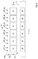
図1に、熱成形可能なシート材料、例えばポリプロピレンから物体32を成形するように構成された成形装置1の第1の実施形態Aが示されている。
FIG. 1 shows a first embodiment A of a forming
材料2は、リール3から繰り出され、進行手段により、複数の作動ステーションを通って進行方向Fに沿って例えば割り出し(indexed)方式で移動する。
The
特に、この進行手段は、駆動ローラ4、複数のローラ7またはギア、および、ガイドプーリ21を含む。前述の作動ステーションは熱調整ステーション5を備え、この熱調整ステーションを通って材料2が進行する。
In particular, the advancing means includes a
熱調整ステーション5は、材料2の厚さ全体にわたって、すなわち、材料2の最も内側の部分の所まで、あるいは、当該技術分野では一般に「中心部(heart)」と呼ばれる所まで材料2を予熱するのに十分な作動温度まで材料2を加熱するように構成された窯6を備える。
The
熱調整ステーション5内では、ローラ7またはギアが、窯6内で十分に長い経路に沿って材料2を所望の作動温度まで加熱されるべく搬送するように位置付けられ、一方、ガイドプーリ21は、材料の割り出し方式での進行中および機械休止時間中の両方において材料2を緊張状態に維持するように位置付けられる。
Within the
前述した作動ステーションは、熱調整ステーション5の下流側に位置付けられる加熱ステーション8を更に備え、該加熱ステーションを通って、窯6によって既に加熱された材料2が進行する。
The aforementioned operating station further comprises a
加熱ステーション8には、材料2の設定部23(図2および図3)を材料2の軟化温度付近の温度まで加熱するために、加熱ステーション8を通じた材料2の略水平な進行方向Fに沿って連続して位置付けられる加熱手段9が設けられる。
In the
特に、窯6および加熱手段9は、熱調整ステーション5と加熱ステーション8との間に介在する材料2の部分11が窯6によって及び/又は加熱手段9によって発生される熱により加熱されるように互いに近接して位置付けられる。
In particular, the
第1の実施形態Aにおいて、装置1は、窯6および加熱手段9の両方を収容する断熱ケース13によって境界付けられる単一の加熱チャンバ12を備える。
In the first embodiment A, the
このようにすると、ほぼ長期にわたる機械休止時間後に装置1が再始動するときに、材料2の部分11を依然として使用できる。
In this way, the
実際に、この部分11は、窯6によって及び/又は加熱手段9によって発生される前述した熱により、正確なその後の成形に適した物理的特性および機械的特性を再始動時に確保するのに十分な均一の温度に維持される。
In fact, this
また、装置1は、かなりのエネルギーを節約できる。これは、加熱手段9によって分散される熱が加熱チャンバ12を加熱するために使用されるからであり、また、断熱ケース13により、既知の装置で起こるように熱が周囲環境に分散されないからである。
The
図4に示される第2の実施形態Bにおいて、装置1は、単一の加熱チャンバ12の代わりに、窯6を収容するための第1の加熱チャンバ14と、第1の加熱チャンバ14と連通する、加熱手段9を収容するための第2の加熱チャンバ15とを備える。
In the second embodiment B shown in FIG. 4, the
特に、第1の加熱チャンバ14は、断熱された第1のケース16によって境界付けられ、一方、第2の加熱チャンバ15は、同様に断熱されて第1のケース16と隣接する、より正確には第1のケース16と接触する第2のケース17によって境界付けられる。第1のケース16と第2のケース17との間に、材料2のための通路33が設けられる。
In particular, the
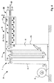
図5に示される第3の実施形態Cは、第1の実施形態Aの変形である。 The third embodiment C shown in FIG. 5 is a modification of the first embodiment A.
第3の実施形態Cは、加熱ステーション8を通った材料2の進行方向Fが略垂直であるため、第1の実施形態Aと異なる。
The third embodiment C is different from the first embodiment A because the traveling direction F of the
したがって、第3の実施形態Cでは、加熱手段9が略垂直に位置付けられる。 Therefore, in the third embodiment C, the heating means 9 is positioned substantially vertically.
このようにすると、ほぼ長期にわたる機械休止時間後の装置1の再始動時に、機械休止時間のときに加熱ステーション8内に収容される材料2の部分20を依然として使用できる。
In this way, when the
実際に、この部分20は、機械休止時間中、重力により、略垂直で平坦な面に沿って配置されたままであり、これにより、再始動時に、この部分20の正確なその後の成形に適した物理的特性および機械的特性が確保される。
In fact, this
また、第3の実施形態Cにおいて、ガイドプーリ21は、材料の割り出し方式での進行中および機械休止時間中の両方において材料2を緊張状態に維持するように進行方向Fに沿った加熱手段9の上流側の加熱ステーション8内に位置付けられる。
Further, in the third embodiment C, the
このようにすると、ガイドプーリ21は、特に機械休止時間中、重力と共に、部分20を前述した略垂直で平坦な面に沿って配置された状態に維持するのに寄与する。
In this way, the
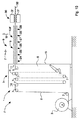
図8に示される第4の実施形態Dは、第2の実施形態Bの変形である。 The fourth embodiment D shown in FIG. 8 is a modification of the second embodiment B.
この第4の実施形態Dは、加熱ステーション8を通った材料2の進行方向Fが略垂直であるため、第2の実施形態Bと異なる。
The fourth embodiment D is different from the second embodiment B because the traveling direction F of the
このようにすると、第4の実施形態Dにおいても、加熱手段9が略垂直に位置付けられる。 If it does in this way, also in 4th Embodiment D, the heating means 9 will be positioned substantially perpendicularly.
第4の実施形態Dにおいても、ガイドプーリ21は、材料の割り出し方式での進行中および機械休止時間中の両方において材料2を緊張状態に維持するように、進行方向Fに沿った加熱手段9の上流側の加熱ステーション8内に位置付けられる。
Also in the fourth embodiment D, the
図9に示される第5の実施形態Eは、第4の実施形態Dの変形である。 The fifth embodiment E shown in FIG. 9 is a modification of the fourth embodiment D.
この第5の実施形態Eは、装置1が、第1の加熱チャンバ14と連通するとともに加熱手段9を収容するための第2の加熱チャンバ15を備えないため、第4の実施形態Dと異なる。
This fifth embodiment E differs from the fourth embodiment D because the
すなわち、第5の実施形態Eでは、窯6を収容する第1の加熱チャンバ14を境界付ける断熱された第1のケース16だけが設けられる。
That is, in the fifth embodiment E, only the heat-insulated
第5の実施形態Eにおいても、加熱手段9が略垂直に位置付けられる。 Also in the fifth embodiment E, the heating means 9 is positioned substantially vertically.
このようにすると、ほぼ長期にわたる機械休止時間後の装置1の再始動時に、機械休止時間のときに加熱ステーション8内に収容される材料2の部分20を依然として使用できる(図6および図7)。
In this way, when the
実際に、この部分20は、機械休止時間中、重力により、略垂直で平坦な面に沿って配置され、これにより、再始動時に、この部分20の正確なその後の成形に適した物理的特性および機械的特性が確保される。
In fact, this
また、第5の実施形態Eにおいても、加熱ステーション8は、材料の割り出し方式での進行中および機械休止時間中の両方において材料2を緊張状態に維持するためのガイドプーリ21を備える。
Also in the fifth embodiment E, the
このようにすると、ガイドプーリ21は、特に機械休止時間中、重力と共に、部分20を前述した略垂直で平坦な面に沿って配置された状態に維持するのに寄与する。
In this way, the
図10に示される第6の実施形態Fは、第2の実施形態Bの変形である。 The sixth embodiment F shown in FIG. 10 is a modification of the second embodiment B.
この第6の実施形態Fは、装置1が、第1の加熱チャンバ14と連通するとともに加熱手段9を収容するための第2の加熱チャンバ15を備えないため、第2の実施形態Bと異なる。
This sixth embodiment F differs from the second embodiment B because the
すなわち、第6の実施形態Fでは、窯6を収容する第1の加熱チャンバ14を境界付ける断熱された第1のケース16だけが設けられる。
That is, in the sixth embodiment F, only the heat-insulated
第6の実施形態Fにおいても、加熱ステーション8は、材料の割り出し方式での進行中および機械休止時間中の両方において材料2を緊張状態に維持するためのガイドプーリ21を備える。
Also in the sixth embodiment F, the
第7の実施形態Gが図11に示されている。 A seventh embodiment G is shown in FIG.
第7の実施形態Gでは、装置1が窯6を欠いている。
In the seventh embodiment G, the
また、第7の実施形態Gにおいて、材料2は、リール3から繰り出され、複数の作動ステーションを通って進行方向Fに沿って進行手段により例えば割り出し方式で移動する。
Further, in the seventh embodiment G, the
特に、この進行手段は、駆動ローラ4、複数のローラ7またはギア、および、ガイドプーリ21を含む。ガイドプーリ21は、材料の割り出し方式での進行中および機械休止時間中の両方において材料2を緊張状態に維持するように位置付けられる。
In particular, the advancing means includes a
加熱ステーション8には、材料2の設定部23(図2および図3)を材料2の軟化温度付近の温度まで加熱するために、加熱ステーション8を通った材料2の略水平な進行方向Fに沿って連続して位置付けられる加熱手段9が設けられる。
In the
加熱ステーション8は、加熱手段9を収容する断熱ケース13を更に備える。
The
特に、ケース13は、略平行六面体である形状を有し、材料2のための入口33および出口66を備える。
In particular, the
このようにすると、ほぼ長期にわたる機械休止時間後の装置1の再始動時に、機械休止時間のときに加熱ステーション8内に収容される材料2の部分20を依然として使用できる。
In this way, when the
実際に、この部分20は、加熱手段9によって発生される熱により、正確なその後の成形に適した物理的特性および機械的特性を再始動時に確保するのに十分に均一な温度に維持される。
In fact, this
また、断熱ケース13が設けられた加熱ステーション8は、かなりのエネルギーの節約を可能にする。これは、加熱手段9によって分散される熱が、前述した部分20を加熱状態に維持するために使用され、既知の装置で起こるように周囲環境中に分散されないからである。
Also, the
第8の実施形態Hが図12に示されている。 An eighth embodiment H is shown in FIG.
第8の実施形態Hでは、装置1が窯6を欠いている。
In the eighth embodiment H, the
また、第8の実施形態Hでは、加熱ステーション8を通った材料2の進行方向Fが略垂直である。
Moreover, in 8th Embodiment H, the advancing direction F of the
したがって、加熱手段9が略垂直に位置付けられる。 Therefore, the heating means 9 is positioned substantially vertically.
このようにすると、ほぼ長期にわたる機械休止時間後の装置1の再始動時に、機械休止時間のときに加熱ステーション8内に収容される材料2の部分20を依然として使用できる(図6および図7)。
In this way, when the
実際に、この部分20は、機械休止時間中、重力により、略垂直で平坦な面に沿って配置され、これにより、再始動時に、この部分20の正確なその後の成形に適した物理的特性および機械的特性が確保される。
In fact, this
この実施形態において、ガイドプーリ21は、材料の割り出し方式での進行中および機械休止時間中の両方において材料2を緊張状態に維持するように進行方向Fに沿った加熱手段9の上流側の加熱ステーション8内に位置付けられる。
In this embodiment, the
このようにすると、ガイドプーリ21は、特に機械休止時間中、重力と共に、部分20を前述した略垂直で平坦な面に沿って配置された状態に維持するのに寄与する。
In this way, the
前述の加熱手段9はプレートの複数の対24,25,26,27,28,29を備える(図2,3,6および7)。
The aforementioned heating means 9 comprises a plurality of
特に、加熱手段9は、進行方向Fに沿って連続して配置される、プレートの第1の対24、プレートの第2の対25、プレートの第3の対26、プレートの第4の対27、プレートの第5の対28、および、プレートの第6の対29を含む。
In particular, the heating means 9 are arranged in succession along the direction of travel F, the
プレートのこれらの対24,25,26,27,28および29は、プレートの第1の対24が残りのプレートの対25,26,27,28および29に対して進行方向Fの更に上流側に位置付けられるように位置付けられる。
These pairs of
プレートの各対24,25,26,27,28および29は、材料の両面を加熱するように、互いに対向するとともに材料2の両側に位置付けられる2つの加熱可能なプレート22を備える。
Each pair of
使用時、プレートの各対24,25,26,27,28および29のプレート22は、進行方向Fに対するとともに略垂直な移動方向Mに沿って移動できる。この移動方向Mは、第1の実施形態A、第2の実施形態B、第6の実施形態F、および、第7の実施形態Gでは略垂直であり、また、第3の実施形態C、第4の実施形態D、第5の実施形態、および、第8の実施形態Hでは略水平である。
In use, the
特に、プレートの各対24,25,26,27,28および29のプレート22は、移動方向Mに沿って移動でき、それにより、プレートが材料2と接触して該材料2をほぼ軟化温度まで加熱する図示しない作動位置と、プレートが材料2から所定の距離を隔てる図1〜図12に示される非作動位置NWとの間で、互いに近づき且つ互いに離れる。
In particular, the
また、使用時、プレートの各対24,25,26,27,28,29は、略水平で且つ進行方向Fおよび移動方向Mに対して実質的に垂直な更なる移動方向N(図3および図7)に沿って移動できる。
Also, in use, each pair of
特に、プレートの各対24,25,26,27,28および29は、プレートの各対24,25,26,27,28および29のプレート22が対向するとともに材料2の対応する部分23から移動方向Mに沿って所定の距離にある図示しない第1の位置と、プレートが互いに対向するとともに材料2に対して側方に位置付けられる図3および図7に示される第2の位置NXとの間で、更なる移動方向Nに沿って移動できる。
In particular, each pair of
より正確には、プレートの各対24,25,26,27,28および29は、機械休止時間中、機械休止時間のときに加熱ステーション8内に収容される材料2の対応する部分23を機械休止時間中に過熱しないように、第2の位置NXに位置付けられる。
More precisely, each pair of
加熱ステーション8は、プレートの各対24,25,26,27,28および29を作動位置と非作動位置NWとの間で駆動するための図示しない制御手段を更に備える。
The
通常の作動ステップにおいて、制御手段は、プレートの対24,25,26,27,28,29を同時に駆動し、それにより、以下の式によって設定される時間にわたってそれぞれの対を対応する作動位置に維持する。
trunning=theating/n
このうち、
trunningは、プレートの対24,25,26,27,28および29が対応する作動位置に走行速度で維持される時間であり;
theatingは、プレートの各対24,25,26,27,28,29に位置付けられてその後に塑性変形されるようになっている部分20の設定部23を軟化させるために必要とされる総加熱時間であり;
nは、プレートの対24,25,26,27,28,29の数(この場合、n=6)
である。
In normal operating steps, the control means drives the plate pairs 24, 25, 26, 27, 28, 29 simultaneously, thereby bringing each pair into the corresponding operating position for a time set by the following equation: maintain.
t running = t heating / n
this house,
trunning is the time during which the plate pairs 24, 25, 26, 27, 28 and 29 are maintained at the corresponding operating positions at the running speed;
t heating is the total required to soften the setting
n is the number of plate pairs 24, 25, 26, 27, 28, 29 (in this case n = 6)
It is.
逆に、機械休止時間後の装置1の再始動ステップにおいて、制御手段は、プレートの対24,25,26,27,28,29を互いに独立に駆動し、それにより、以下の式によって設定される時間にわたってプレートの対24,25,26,27,28,29をそれぞれ対応する作動位置に維持する。
trestart(i)=trunning×p(i)
このうち、
trestart(i)(i=1,....m)は、i番目のプレートの対24,25,26,27,28,29の再始動時の対応する作動位置での維持時間であり;
trunningは、プレートの対24,25,26,27,28,29の走行速度における対応する作動位置での維持時間であり、;
p(i)(i=1,....m)は、加熱ステーション8内での進行方向Fに関してi番目のプレートの対24,25,26,27,28,29の位置であり、i=1は、進行方向Fに関して更に上流側のプレートの第1の対24の位置を示し、また、i=6は、進行方向Fに関して更に下流側に位置付けられるプレートの第6の対29の位置を示す。
Conversely, in the restarting step of the
t restart (i) = t running * p (i)
this house,
t restart (i) (i = 1,... m) is the maintenance time at the corresponding operating position at the restart of the i-
trunning is the maintenance time at the corresponding operating position at the travel speed of the plate pairs 24, 25, 26, 27, 28, 29;
p (i) (i = 1,... m) is the position of the i-
言い換えると、再始動時、プレートの対24,25,26,27,28および29は、以下の時間、すなわち、
プレートの第1の対24に関しては、trestart(1)=trunning×1;
プレートの第2の対25に関しては、trestart(2)=trunning×2;
プレートの第3の対26に関しては、trestart(3)=trunning×3;
プレートの第4の対27に関しては、trestart(4)=trunning×4;
プレートの第5の対28に関しては、trestart(5)=trunning×5;
プレートの第6の対29に関しては、trestart(6)=trunning×6;
の時間にわたって対応する作動位置にそれぞれ維持される。
In other words, upon restart, the plate pairs 24, 25, 26, 27, 28 and 29 are in the following times:
For the
For the
For the third pair of
For the
For the fifth pair of
For the
Are maintained in corresponding operating positions for a period of time.
特に、この再始動ステップ中、プレートの第6の対29を最初に駆動し、その後、プレートの第6の対29よりも更に上流側に位置付けられるプレートの対24,25,26,27,28を、以下の式により設定される遅延をもって駆動する。
tdriving(j)(j=1,...m−1)=tm+trunning×(p(m)−p(m―j))
このうち、
tdriving(j)(j=1,...m−1)は、対応する作動位置における、進行方向Fに関して更に下流側に位置付けられるプレートの対29の上流側に位置付けられるj番目のプレートの対24,25,26,27,28を再始動させるための時間であり;
tmは、進行方向Fに関して更に下流側に位置付けられるプレートの対24,25,26,27,28,29を駆動する時間であり;
trunningは、プレートの対24,25,26,27,28,29の走行速度における対応する作動位置での維持時間であり、;
p(m)は、進行方向Fに関して更に下流側に位置付けられる加熱ステーション8内のm番目のプレートの対29の位置であり、例えば、プレートの第6の対29に関してはp(m)=6であり;
p(m―j)(j=1,...m−1)は、加熱ステーション8内の(m−j)番目のプレートの対24,25,26,27,28の位置であり、例えば、プレートの第5の対28に関してはp(m―j)=1である。
In particular, during this restarting step, the
t driving (j) (j = 1,... m−1) = t m + t running × (p (m) −p (m−j) )
this house,
t driving (j) (j = 1,..., m−1) is the jth plate positioned upstream of the
t m is the time to drive the pair of
trunning is the maintenance time at the corresponding operating position at the travel speed of the plate pairs 24, 25, 26, 27, 28, 29;
p (m) is the position of the m-
p (m−j) (j = 1,... m−1) is the position of the (m−j)
例えば、theating=12秒、trunning=theating/n=12秒/6=2秒においては、再始動時、プレートの対24,25,26,27,28,29は、以下の時間、すなわち、
プレートの第6の対29に関しては、tm;
プレートの第5の対28に関しては、trestart(5)=tm+2秒×(6−5)=tm+2秒;
プレートの第4の対27に関しては、trestart(4)=tm+2秒×(6−4)=tm+4秒;
プレートの第3の対26に関しては、trestart(3)=tm+2秒×(6−3)=tm+6秒;
プレートの第2の対25に関しては、trestart(2)=tm+2秒×(6−2)=tm+8秒;
プレートの第1の対24に関しては、trestart(1)=tm+2秒×(6−1)=tm+10秒;
の時間にそれぞれ駆動される。
For example, at t heating = 12 seconds and t running = t heating / n = 12 seconds / 6 = 2 seconds, at the time of restart, the plate pairs 24, 25, 26, 27, 28, 29 have the following times: That is,
For the
For the fifth pair of
For the
For the third pair of
For the
For the
It is driven at each time.
再始動の終わりに、制御手段は、プレートの対のそれぞれをtrunning時間にわたって対応する作動位置に維持することによってプレートの対24,25,26,27,28,29を再び同時に駆動する。 At the end of the restart, the control means simultaneously drives the plate pairs 24, 25, 26, 27, 28, 29 again by maintaining each of the plate pairs in the corresponding operating position for the trunning time.
このようにすると、材料を割り出し方式で進めることにより、全ての設定部23が、設定部23を軟化させて塑性変形させることができるようにする温度まで加熱される。
If it does in this way, all the setting
例えば、theating=12秒、trunning=theating/n=12秒/6=2秒においては、再始動時、以下のようになる。
プレートの第1の対24に関しては、trestart(1)=2×1=2秒;
プレートの第2の対25に関しては、trestart(2)=2×2=4秒;
プレートの第3の対26に関しては、trestart(3)=2×3=6秒;
プレートの第4の対27に関しては、trestart(4)=2×4=8秒;
プレートの第5の対28に関しては、trestart(5)=2×5=10秒;
プレートの第6の対29に関しては、trestart(6)=2×6=12秒。
For example, when t heating = 12 seconds and t running = t heating / n = 12 seconds / 6 = 2 seconds, at the time of restart, the following occurs.
For the
For the
For the third pair of
For the
For the fifth pair of
For the
このようにすると、ほぼ長期にわたる機械休止時間後の装置1の再始動時に、機械休止時間のときに加熱ステーション8内に収容される材料の部分20を依然として再使用できる。これは、各設定部23が加熱ステーション8から出る前に設定部23を軟化させてその後に塑性変形させることができるようにする温度まで加熱されるからである。
In this way, when the
そうするために、プレートの対25,26,27,28および29をプレートの第1の対24から離間させる距離が増大するにつれて増大する時間間隔にわたって、進行方向Fに関してプレートの第1の対24から順に下流側に位置付けられるプレートの対25,26,27,28および29が対応する作動位置にとどまるように、制御手段は、プレートの対24,25,26,27,28および29のそれぞれを対応する作動位置に維持する。
To do so, the first pair of
図示しない本発明の1つの実施形態では、プレートの対が6個よりも多く或いは少なくなっている。 In one embodiment of the invention not shown, there are more or fewer plate pairs than six.
更にその後、プレートの対24,25,26,27,28および29によってこのように軟化された材料2が成形ステーション30を通過し、該成形ステーション30では、所望の物体32を得るために材料2が成形手段31によって塑性変形される。
Further thereafter, the
また、成形ステーション30の下流側に図示しない剪断ステーションを設けることができ、この剪断ステーションでは、適した切断手段が、得られた材料2のシートから成形された物体32を分離する。
In addition, a shearing station (not shown) can be provided downstream of the
Claims (11)
前記材料(2)を作動温度まで加熱するための窯(6)を含む熱調整ステーション(5)と、前記熱調整ステーション(5)の下流側に位置付けられ、前記材料(2)の設定部(23)を前記材料(2)の軟化温度付近の温度まで加熱する加熱手段(9)を含む加熱ステーション(8)とを備え、
前記加熱手段(9)が、前記加熱ステーション(8)内に、前記材料(2)の進行方向(F)に沿って位置付けられ、
前記熱調整ステーション(5)と前記加熱ステーション(8)との間に介在される前記材料(2)の部分(11)が、前記窯(6)によって及び/又は前記加熱手段(9)によって発生される熱により加熱されるように、前記窯(6)および前記加熱手段(9)が、互いに近接して位置付けられ、
前記加熱手段(9)が、互いに対向するとともに前記材料(2)の両側に位置付けられる加熱可能なプレート(22)の対(24)と、少なくとも1つの更なる対(25,26,27,28,29)と、を備え、
前記プレートが前記材料(2)と接触して該材料を加熱する作動位置と、前記材料(2)から所定の距離を隔てる非作動位置(NW)との間で、前記プレート(22)が、前記進行方向(F)に対して略垂直な移動方向(M)に沿って、互いに近づき且つ離れることができ、
当該成形装置は、プレート(22)の前記対(24)とプレート(22)の前記少なくとも1つの更なる対(25,26,27,28,29)を、前記作動位置と前記非作動位置との間で互いに独立に駆動する制御手段を備えることを特徴とする成形装置。 A molding apparatus for molding an object (32) by molding a sheet of thermoformable material (2),
A thermal conditioning station (5) including a kiln (6) for heating the material (2) to an operating temperature, and a setting part (of the material (2) positioned downstream of the thermal conditioning station (5) ( A heating station (8) comprising heating means (9) for heating 23) to a temperature close to the softening temperature of said material (2),
The heating means (9) is positioned in the heating station (8) along the direction of travel (F) of the material (2);
The part (11) of the material (2) interposed between the thermal conditioning station (5) and the heating station (8) is generated by the kiln (6) and / or by the heating means (9). to be heated by the heat, the kiln (6) and said heating means (9) is positioned proximate to each other,
A pair (24) of heatable plates (22), wherein said heating means (9) face each other and are located on both sides of said material (2), and at least one further pair (25, 26, 27, 28) , 29), and
Between an operating position where the plate contacts and heats the material (2) and a non-operating position (NW) spaced a predetermined distance from the material (2), the plate (22) Can move toward and away from each other along a movement direction (M) substantially perpendicular to the direction of travel (F);
The forming apparatus includes the pair (24) of plates (22) and the at least one further pair (25, 26, 27, 28, 29) of plates (22), the operating position and the non-operating position. A molding apparatus comprising control means that are driven independently from each other .
Applications Claiming Priority (9)
| Application Number | Priority Date | Filing Date | Title |
|---|---|---|---|
| ITMO2010A000224 | 2010-08-02 | ||
| ITMO2010A000224A IT1401328B1 (en) | 2010-08-02 | 2010-08-02 | FORMING APPARATUS |
| ITMO2010A000226 | 2010-08-02 | ||
| ITMO2010A000225 | 2010-08-02 | ||
| ITMO2010A000227A IT1401331B1 (en) | 2010-08-02 | 2010-08-02 | HEATING STATION |
| ITMO2010A000227 | 2010-08-02 | ||
| ITMO2010A000225A IT1401329B1 (en) | 2010-08-02 | 2010-08-02 | STATION AND HEATING METHOD |
| ITMO2010A000226A IT1401330B1 (en) | 2010-08-02 | 2010-08-02 | HEATING STATION |
| PCT/IB2011/053298 WO2012017352A1 (en) | 2010-08-02 | 2011-07-25 | Forming apparatus, heating station and method for heating set portions |
Related Child Applications (1)
| Application Number | Title | Priority Date | Filing Date |
|---|---|---|---|
| JP2015075058A Division JP6140754B2 (en) | 2010-08-02 | 2015-04-01 | Heating method |
Publications (3)
| Publication Number | Publication Date |
|---|---|
| JP2013532598A JP2013532598A (en) | 2013-08-19 |
| JP2013532598A5 JP2013532598A5 (en) | 2014-06-05 |
| JP5727608B2 true JP5727608B2 (en) | 2015-06-03 |
Family
ID=45558991
Family Applications (2)
| Application Number | Title | Priority Date | Filing Date |
|---|---|---|---|
| JP2013522324A Active JP5727608B2 (en) | 2010-08-02 | 2011-07-25 | Molding equipment |
| JP2015075058A Expired - Fee Related JP6140754B2 (en) | 2010-08-02 | 2015-04-01 | Heating method |
Family Applications After (1)
| Application Number | Title | Priority Date | Filing Date |
|---|---|---|---|
| JP2015075058A Expired - Fee Related JP6140754B2 (en) | 2010-08-02 | 2015-04-01 | Heating method |
Country Status (7)
| Country | Link |
|---|---|
| US (2) | US9403313B2 (en) |
| EP (2) | EP2601038B1 (en) |
| JP (2) | JP5727608B2 (en) |
| CN (2) | CN105082519B (en) |
| CA (1) | CA2807100C (en) |
| ES (2) | ES2668372T3 (en) |
| WO (1) | WO2012017352A1 (en) |
Families Citing this family (8)
| Publication number | Priority date | Publication date | Assignee | Title |
|---|---|---|---|---|
| US10314320B2 (en) | 2015-03-20 | 2019-06-11 | Meltz, LLC | Systems for controlled liquid food or beverage product creation |
| US9487348B2 (en) | 2015-03-20 | 2016-11-08 | Meltz, LLC | Systems for and methods of providing support for displaceable frozen contents in beverage and food receptacles |
| US9346611B1 (en) | 2015-03-20 | 2016-05-24 | Meltz, LLC | Apparatus and processes for creating a consumable liquid food or beverage product from frozen contents |
| US10111554B2 (en) | 2015-03-20 | 2018-10-30 | Meltz, LLC | Systems for and methods of controlled liquid food or beverage product creation |
| JP6583618B2 (en) * | 2015-06-08 | 2019-10-02 | 株式会社浅野研究所 | Thermoforming method |
| CN108137182B (en) * | 2015-08-06 | 2020-06-02 | 莫迪维克西普哈根牧勒股份及两合公司 | Packaging machine with process-controlled early start function |
| MX2019012834A (en) | 2017-04-27 | 2019-12-16 | Meltz Llc | Method for centrifugal extraction and apparatus suitable for carrying out this method. |
| US11724849B2 (en) | 2019-06-07 | 2023-08-15 | Cometeer, Inc. | Packaging and method for single serve beverage product |
Family Cites Families (23)
| Publication number | Priority date | Publication date | Assignee | Title |
|---|---|---|---|---|
| DE1151922B (en) * | 1958-09-06 | 1963-07-25 | Dornbusch & Co | Device for preheating of subsequently to be embossed material webs made of thermoplastics |
| US3281957A (en) | 1963-04-22 | 1966-11-01 | Production Machinery Corp | Apparatus for processing strip material |
| US3331908A (en) * | 1963-12-26 | 1967-07-18 | Monsanto Co | Molding machines |
| GB1051398A (en) * | 1965-01-12 | 1966-12-14 | ||
| US4172869A (en) * | 1977-04-11 | 1979-10-30 | Kurashiki Boseki Kabushiki Kaisha | Method of and apparatus for manufacturing fiber-reinforced thermoplastic resin of cellular structure |
| DE2745422C3 (en) * | 1977-10-08 | 1982-08-26 | Société d'Application Plastique, Mécanique et Electronique Plastimécanique S.A., 14700 Falaise | Method for operating a thermoforming machine and device for carrying out the method |
| US4306856A (en) * | 1979-09-14 | 1981-12-22 | Raimondo Arippol | Pre-heating apparatus for a thermoforming machine |
| US5268136A (en) * | 1980-04-17 | 1993-12-07 | Saint-Gobain Vitrage International | Method for the manufacture of plastic sheets of good optical quality |
| EP0146700B1 (en) * | 1983-10-06 | 1990-04-18 | Servichem AG | Device for manufacturing of articles from a web of a thermoplastic sheet and its use for producing parts of containers |
| GB8513345D0 (en) * | 1985-05-28 | 1985-07-03 | Busm Co Ltd | Gauge control of heat-softenable material |
| DE8527284U1 (en) * | 1985-09-25 | 1985-11-07 | KMB Kunststoffmetallbearbeitung GmbH, 7107 Neckarsulm | Heating device for webs to be unwound from rolls |
| US4892689A (en) | 1987-07-14 | 1990-01-09 | Agfa-Gevaert N.V. | Process for making curled photographic film |
| US5125994A (en) | 1989-11-01 | 1992-06-30 | Eastman Kodak Company | Thermoforming method |
| JP2862774B2 (en) * | 1993-10-14 | 1999-03-03 | 住友重機械工業株式会社 | Foam molding method and foam molding apparatus |
| JPH091645A (en) * | 1995-06-21 | 1997-01-07 | Matsushita Electric Ind Co Ltd | Strip like film molding apparatus |
| DE10147673A1 (en) * | 2001-09-27 | 2003-04-10 | Bosch Gmbh Robert | Thermoforming apparatus |
| CH695724A5 (en) | 2002-09-30 | 2006-08-15 | Bosch Gmbh Robert | Form, fill and seal system, for plastic pots, has heater moving together with plastic strip and acting as additional conveyor |
| AU2003287303A1 (en) * | 2002-11-01 | 2004-06-07 | Sencorp Systems, Inc. | Robotic method and apparatus for removing parts from the trim press of a thermoforming system |
| KR20040057969A (en) * | 2002-12-25 | 2004-07-02 | 스미또모 가가꾸 고오교오 가부시끼가이샤 | Apparatus and method for producing a thermoplastic resin continuous laminated sheet |
| ITMI20030768A1 (en) | 2003-04-11 | 2004-10-12 | Amut Spa | DEVICE FOR THE HEAT TREATMENT OF PLASTIC MATERIAL. |
| JP4694475B2 (en) * | 2004-03-26 | 2011-06-08 | 出光ユニテック株式会社 | Method for producing transparent polypropylene sheet and transparent polypropylene sheet |
| US7832852B2 (en) * | 2007-07-16 | 2010-11-16 | Xerox Corporation | Continuous media web heater |
| DE102008062199A1 (en) * | 2008-05-29 | 2009-12-03 | Fraunhofer-Gesellschaft zur Förderung der angewandten Forschung e.V. | Method and heater for thermoforming |
-
2011
- 2011-07-25 US US13/813,823 patent/US9403313B2/en active Active
- 2011-07-25 CN CN201510544511.4A patent/CN105082519B/en not_active Expired - Fee Related
- 2011-07-25 ES ES15160619.1T patent/ES2668372T3/en active Active
- 2011-07-25 WO PCT/IB2011/053298 patent/WO2012017352A1/en active Application Filing
- 2011-07-25 ES ES11746665.6T patent/ES2540860T3/en active Active
- 2011-07-25 JP JP2013522324A patent/JP5727608B2/en active Active
- 2011-07-25 CA CA2807100A patent/CA2807100C/en not_active Expired - Fee Related
- 2011-07-25 EP EP11746665.6A patent/EP2601038B1/en active Active
- 2011-07-25 EP EP15160619.1A patent/EP2915654B1/en active Active
- 2011-07-25 CN CN201180045323.7A patent/CN103180121B/en not_active Expired - Fee Related
-
2015
- 2015-04-01 JP JP2015075058A patent/JP6140754B2/en not_active Expired - Fee Related
-
2016
- 2016-06-15 US US15/183,121 patent/US9884446B2/en not_active Expired - Fee Related
Also Published As
| Publication number | Publication date |
|---|---|
| EP2601038A1 (en) | 2013-06-12 |
| ES2668372T3 (en) | 2018-05-17 |
| EP2601038B1 (en) | 2015-04-01 |
| EP2915654B1 (en) | 2018-02-14 |
| US9403313B2 (en) | 2016-08-02 |
| JP6140754B2 (en) | 2017-05-31 |
| CA2807100C (en) | 2018-08-21 |
| CN103180121B (en) | 2015-08-26 |
| US9884446B2 (en) | 2018-02-06 |
| US20130193616A1 (en) | 2013-08-01 |
| CN105082519B (en) | 2018-11-02 |
| CN105082519A (en) | 2015-11-25 |
| ES2540860T3 (en) | 2015-07-14 |
| WO2012017352A1 (en) | 2012-02-09 |
| CN103180121A (en) | 2013-06-26 |
| CA2807100A1 (en) | 2012-02-09 |
| JP2013532598A (en) | 2013-08-19 |
| JP2015147422A (en) | 2015-08-20 |
| US20160361861A1 (en) | 2016-12-15 |
| EP2915654A1 (en) | 2015-09-09 |
Similar Documents
| Publication | Publication Date | Title |
|---|---|---|
| JP6140754B2 (en) | Heating method | |
| KR101558956B1 (en) | Production method and production device of film having fine irregular pattern on surface | |
| EG25090A (en) | Method and apparatus for producing oriented slit film tapes. | |
| TWI510376B (en) | Transfer formation method and transfer formation device | |
| TW201302437A (en) | In-line apparatus for extrusion molding and pattern forming | |
| JP2013532598A5 (en) | ||
| CN104768730B (en) | Transfer molding method, mould structure, transfer molding device and optical component | |
| JP6829814B2 (en) | Glass film manufacturing method | |
| JP5684582B2 (en) | Manufacturing method of resin foam molded product and resin foam molded product manufacturing equipment | |
| JP2011062955A (en) | Device and method for resin sealing | |
| JP2019026509A (en) | Method for manufacturing glass film | |
| ITMO20100224A1 (en) | FORMING APPARATUS | |
| ITMO20100226A1 (en) | HEATING STATION | |
| ITMO20100225A1 (en) | STATION AND HEATING METHOD | |
| ITMO20100227A1 (en) | HEATING STATION | |
| KR101486365B1 (en) | Apparatus and method of manufacturing Plastic corrugated carboard | |
| JP7384046B2 (en) | Glass film manufacturing method | |
| TW202415538A (en) | A film lamination device | |
| JP5139157B2 (en) | Thermoplastic resin processing method and processing apparatus | |
| JP2011161807A (en) | Heating method of sheet and apparatus therefor | |
| KR20150121878A (en) | Insulation vunyl manufacture machine |
Legal Events
| Date | Code | Title | Description |
|---|---|---|---|
| A521 | Written amendment |
Free format text: JAPANESE INTERMEDIATE CODE: A523 Effective date: 20140416 |
|
| A621 | Written request for application examination |
Free format text: JAPANESE INTERMEDIATE CODE: A621 Effective date: 20140416 |
|
| A977 | Report on retrieval |
Free format text: JAPANESE INTERMEDIATE CODE: A971007 Effective date: 20150226 |
|
| TRDD | Decision of grant or rejection written | ||
| A01 | Written decision to grant a patent or to grant a registration (utility model) |
Free format text: JAPANESE INTERMEDIATE CODE: A01 Effective date: 20150303 |
|
| A61 | First payment of annual fees (during grant procedure) |
Free format text: JAPANESE INTERMEDIATE CODE: A61 Effective date: 20150402 |
|
| R150 | Certificate of patent or registration of utility model |
Ref document number: 5727608 Country of ref document: JP Free format text: JAPANESE INTERMEDIATE CODE: R150 |
|
| R250 | Receipt of annual fees |
Free format text: JAPANESE INTERMEDIATE CODE: R250 |
|
| R250 | Receipt of annual fees |
Free format text: JAPANESE INTERMEDIATE CODE: R250 |
|
| R250 | Receipt of annual fees |
Free format text: JAPANESE INTERMEDIATE CODE: R250 |